conference microphone speaker - yamaha
TRANSCRIPT

Conference Microphone Speaker
OWNER’S MANUALMODE D’EMPLOI
BEDIENUNGSANLEITUNG
UCGB
01EN_PJP-100UH_UCGB_cv-1.fm Page 1 Tuesday, April 17, 2007 10:58 AM

IMPORTANT SAFETY INSTRUCTIONS
i
• Explanation of Graphical Symbols
The lightning flash with arrowhead symbol, within an
equilateral triangle, is intended to alert you to the
presence of uninsulated “dangerous voltage” within
the product’s enclosure that may be of sufficient
magnitude to constitute a risk of electric shock to
persons.
The exclamation point within an equilateral triangle
is intended to alert you to the presence of important
operating and maintenance (servicing) instructions in
the literature accompanying the appliance.
1 Read Instructions – All the safety and operating instructions
should be read before the product is operated.
2 Retain Instructions – The safety and operating instructions
should be retained for future reference.
3 Heed Warnings – All warnings on the product and in the
operating instructions should be adhered to.
4 Follow Instructions – All operating and use instructions
should be followed.
5 Cleaning – Unplug this product from the wall outlet before
cleaning. Do not use liquid cleaners or aerosol cleaners.
6 Attachments – Do not use attachments not recommended by
the product manufacturer as they may cause hazards.
7 Water and Moisture – Do not use this product near water –
for example, near a bath tub, wash bowl, kitchen sink, or
laundry tub; in a wet basement; or near a swimming pool;
and the like.
8 Accessories – Do not place this product on an unstable cart,
stand, tripod, bracket, or table. The product may fall,
causing serious injury to a child or adult, and serious
damage to the product. Use only with a cart, stand, tripod,
bracket, or table recommended by the manufacturer, or sold
with the product. Any mounting of the product should
follow the manufacturer’s instructions, and should use a
mounting accessory recommended by the manufacturer.
9 A product and cart combination should be moved with care.
Quick stops, excessive force, and uneven surfaces may
cause the product and cart combination to
overturn.
10 Ventilation – Slots and openings in the cabinet are provided
for ventilation and to ensure reliable operation of the
product and to protect it from overheating, and these
openings must not be blocked or covered. The openings
should never be blocked by placing the product on a bed,
sofa, rug, or other similar surface. This product should not
be placed in a built-in installation such as a bookcase or rack
unless proper ventilation is provided or the manufacturer’s
instructions have been adhered to.
11 Power Sources – This product should be operated only from
the type of power source indicated on the marking label. If
you are not sure of the type of power supply to your home,
consult your product dealer or local power company. For
products intended to operate from battery power, or other
sources, refer to the operating instructions.
12 Grounding or Polarization – This product may be equipped
with a polarized alternating current line plug (a plug having
one blade wider than the other). This plug will fit into the
power outlet only one way. This is a safety feature. If you
are unable to insert the plug fully into the outlet, try
reversing the plug. If the plug should still fail to fit, contact
your electrician to replace your obsolete outlet. Do not
defeat the safety purpose of the polarized plug.
13 Power-Cord Protection – Power-supply cords should be
routed so that they are not likely to be walked on or pinched
by items placed upon or against them, paying particular
attention to cords at plugs, convenience receptacles, and the
point where they exit from the product.
14 Lightning – For added protection for this product during a
lightning storm, or when it is left unattended and unused for
long periods of time, unplug it from the wall outlet and
disconnect the antenna or cable system. This will prevent
damage to the product due to lightning and power-line
surges.
15 Power Lines – An outside antenna system should not be
located in the vicinity of overhead power lines or other
electric light or power circuits, or where it can fall into such
power lines or circuits. When installing an outside antenna
system, extreme care should be taken to keep from touching
such power lines or circuits as contact with them might be
fatal.
16 Overloading – Do not overload wall outlets, extension
cords, or integral convenience receptacles as this can result
in a risk of fire or electric shock.
17 Object and Liquid Entry – Never push objects of any kind
into this product through openings as they may touch
dangerous voltage points or short-out parts that could result
in a fire or electric shock. Never spill liquid of any kind on
the product.
18 Servicing – Do not attempt to service this product yourself
as opening or removing covers may expose you to
dangerous voltage or other hazards. Refer all servicing to
qualified service personnel.
19 Damage Requiring Service – Unplug this product from the
wall outlet and refer servicing to qualified service personnel
under the following conditions:
a) When the power-supply cord or plug is damaged,
b) If liquid has been spilled, or objects have fallen into the
product,
c) If the product has been exposed to rain or water,
IMPORTANT SAFETY INSTRUCTIONS
CAUTION
CAUTION: TO REDUCE THE RISK OF ELECTRIC SHOCK, DO NOT REMOVE
COVER (OR BACK). NO USER-SERVICEABLE PARTS INSIDE. REFER SERVICING TO
QUALIFIED SERVICE PERSONNEL.
RISK OF ELECTRIC SHOCK DO NOT OPEN
01EN_00_PJP-100UH_UCGB.book Page i Thursday, October 19, 2006 9:18 AM
IMPORTANT SAFETY INSTRUCTIONS
ii
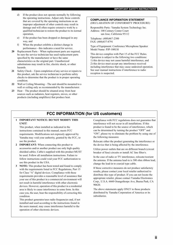
d) If the product does not operate normally by following
the operating instructions. Adjust only those controls
that are covered by the operating instructions as an
improper adjustment of other controls may result in
damage and will often require extensive work by a
qualified technician to restore the product to its normal
operation,
e) If the product has been dropped or damaged in any
way, and
f) When the product exhibits a distinct change in
performance - this indicates a need for service.
20 Replacement Parts – When replacement parts are required,
be sure the service technician has used replacement parts
specified by the manufacturer or have the same
characteristics as the original part. Unauthorized
substitutions may result in fire, electric shock, or other
hazards.
21 Safety Check – Upon completion of any service or repairs to
this product, ask the service technician to perform safety
checks to determine that the product is in proper operating
condition.
22 Wall or Ceiling Mounting – The unit should be mounted to a
wall or ceiling only as recommended by the manufacturer.
23 Heat – The product should be situated away from heat
sources such as radiators, heat registers, stoves, or other
products (including amplifiers) that produce heat.
COMPLIANCE INFORMATION STATEMENT(DECLARATION OF CONFORMITY PROCEDURE)
Responsible Party: Yamaha System Technology Inc.
Address: 100 Century Center Court
san Jose, California 95112
Telephone: (408)467-2300
FAX: (408)437-8791
Type of Equipment: Conference Microphone Speaker
Model Name: PJP-100UH
This device complies with Part 15 of the FCC Rules.
Operation is subject to the following two conditions:
1) this device may not cause harmful interference, and
2) this device must accept any interference received
including interference that may cause undesired operation.
See user manual instructions if interference to radio
reception is suspected.
FCC INFORMATION (for US customers)1 IMPORTANT NOTICE: DO NOT MODIFY THIS
UNIT!
This product, when installed as indicated in the
instructions contained in this manual, meets FCC
requirements. Modifications not expressly approved by
Yamaha may void your authority, granted by the FCC, to
use the product.
2 IMPORTANT: When connecting this product to
accessories and/or another product use only high quality
shielded cables. Cable/s supplied with this product MUST
be used. Follow all installation instructions. Failure to
follow instructions could void your FCC authorization to
use this product in the USA.
3 NOTE: This product has been tested and found to comply
with the requirements listed in FCC Regulations, Part 15
for Class “A” digital devices. Compliance with these
requirements provides a reasonable level of assurance that
your use of this product in a commercial environment will
not result in harmful interference with other electronic
devices. However, operation of this product in a residential
area is likely to cause interference in some form. In this
case you, the user, bear the responsibility of correcting this
condition.
This product generates/uses radio frequencies and, if not
installed and used according to the instructions found in
the users manual, may cause interference harmful to the
operation of other electronic devices.
Compliance with FCC regulations does not guarantee that
interference will not occur in all installations. If this
product is found to be the source of interference, which
can be determined by turning the product “OFF” and
“ON”, please try to eliminate the problem by using one of
the following measures:
Relocate either the product generating the interference or
the device that is being affected by the interference.
Utilize power outlets that are on different branch (circuit
breaker of fuse) circuits or install AC line filter/s.
In the case of radio or TV interference, relocate/reorient
the antenna. If the antenna lead-in is 300 ohm ribbon lead,
change the lead-in to coaxial type cable.
If these corrective measures do not produce satisfactory
results, please contact your local retailer authorized to
distribute this type of product. If you can not locate the
appropriate retailer, please contact Yamaha Electronics
Corp., U.S.A. 6660 Orangethorpe Ave, Buena Park, CA
90620.
The above statements apply ONLY to those products
distributed by Yamaha Corporation of America or its
subsidiaries.
01EN_00_PJP-100UH_UCGB.book Page ii Thursday, October 19, 2006 9:18 AM

iii
1 To assure the finest performance, please read this manual
carefully. Keep it in a safe place for future reference.
2 Install this unit in a well ventilated, cool, dry, clean place with at
least 10 cm on the top, 10 cm on the left and right, and 10 cm at
the back of this unit — away from direct sunlight, heat sources,
vibration, dust, moisture, and/or cold.
3 Locate this unit away from other electrical appliances, motors, or
transformers to avoid humming sounds.
4 Do not expose this unit to sudden temperature changes from cold
to hot, and do not locate this unit in an environment with high
humidity (i.e. a room with a humidifier) to prevent condensation
inside this unit, which may cause an electrical shock, fire,
damage to this unit, and/or personal injury.
5 Avoid installing this unit where foreign object may fall onto this
unit and/or this unit may be exposed to liquid dripping or
splashing. On the top of this unit, do not place:
– Other components, as they may cause damage and/or
discoloration on the surface of this unit.
– Burning objects (i.e. candles), as they may cause fire, damage
to this unit, and/or personal injury.
– Containers with liquid in them, as they may fall and liquid
may cause electrical shock to the user and/or damage to this
unit.
6 Do not cover this unit with a newspaper, tablecloth, curtain, etc.
in order not to obstruct heat radiation. If the temperature inside
this unit rises, it may cause fire, damage to this unit, and/or
personal injury.
7 Do not plug in this unit to a wall outlet until all connections are
complete.
8 Do not operate this unit upside-down. It may overheat, possibly
causing damage.
9 Do not use force on switches, knobs and/or cords.
10 When disconnecting the power cable from the wall outlet, grasp
the plug; do not pull the cable.
11 Do not clean this unit with chemical solvents; this might damage
the finish. Use a clean, dry cloth.
12 Only voltage specified on this unit must be used. Using this unit
with a higher voltage than specified is dangerous and may cause
fire, damage to this unit, and/or personal injury. YAMAHA will
not be held responsible for any damage resulting from use of this
unit with a voltage other than specified.
13 Do not attempt to modify or fix this unit. Contact qualified
YAMAHA service personnel when any service is needed.
The cabinet should never be opened for any reasons.
14 When not planning to use this unit for long periods of time (i.e.
vacation), disconnect the AC power plug from the wall outlet.
15 Be sure to read the “TROUBLESHOOTING” section on
common operating errors before concluding that this unit is
faulty.
16 Before moving this unit, press and hold MIC MUTE for 3
seconds to set this unit in standby mode, and disconnect the AC
power plug from the wall outlet.
17 Condensation will form when the surrounding temperature
changes suddenly. Disconnect the power cable from the outlet,
then leave the unit alone.
18 When using the unit for a long time, the unit may become warm.
Turn the power off, then leave the unit alone for cooling.
19 Install this unit near the wall outlet and where the AC power plug
can be reached easily.
■ For U.K. customersIf the socket outlets in the home are not suitable for the plug
supplied with this appliance, it should be cut off and an
appropriate 3 pin plug fitted. For details, refer to the instructions
described below.
The plug severed from the mains lead must be destroyed, as a
plug with bared flexible cord is hazardous if engaged in a live
socket outlet.
■ Special Instructions for U.K. Model
CAUTION: READ THIS BEFORE OPERATING YOUR UNIT.
This unit is not disconnected from the AC power source as
long as it is connected to the AC wall outlet, even if this unit
itself is turned off. This state is called the standby mode. In
this state, this unit is designed to consume a very small quan-
tity of power.
FOR CANADIAN CUSTOMERSTo prevent electric shock, match wide blade of plug to wide
slot and fully insert.
This Class A digital apparatus complies with Canadian
ICES-003.
WARNINGTO REDUCE THE RISK OF FIRE OR ELECTRIC SHOCK,
DO NOT EXPOSE THIS UNIT TO RAIN OR MOISTURE.
WARNINGTHE POWER SUPPLY CABLE OF THIS UNIT MUST BE
CONNECTED TO THE MAIN SOCKET OUTLET VIA A
PROTECTIVE EARTHING CONNECTION.
WARNINGThis is a class A product. In a domestic environment this
product may cause radio interference in which case the user
may be required to take adequate measures.
Note
WARNING-THIS APPARATUS MUST BE EARTHED.IMPORTANTTHE WIRES IN THIS MAINS LEAD ARE COLOURED
IN ACCORDANCE WITH THE FOLLOWING CODE:
GREEN-AND-YELLOW:EARTH
BLUE:NEUTRAL
BROWN:LIVE
As the colours of the wires in the mains lead of this appa-
ratus may not correspond with the coloured markings
identifying the terminals in your plug, proceed as follows:
The wire which is coloured GREEN-AND-YELLOW
must be connected to the terminal in the plug which is
marked by the letter E or by the safety earth symbol or
coloured GREEN or GREEN-and-YELLOW.
The wire which is coloured BLUE must be connected to the ter-
minal which is marked with the letter N or coloured BLACK.
The wire which is coloured BROWN must be connected to the
terminal which is marked with the letter L or coloured RED.
01EN_00_PJP-100UH_UCGB.book Page iii Thursday, October 19, 2006 9:18 AM
1
PR
EPA
RA
TIO
NIN
TR
OD
UC
TIO
NC
ON
FIGU
RATIO
NS
AD
DIT
ION
AL
IN
FO
RM
AT
ION
En
glish
FEATURES ............................................................ 2SUPPLIED ACCESSORIES ................................ 3CONTROLS AND FUNCTIONS ........................ 4
PREPARATION PROCEDURE ......................... 7Step 1: Connecting this unit....................................... 8
Step 2: Changing the settings of PC .......................... 9
Step 3: Installing this unit in the conference room.. 11
CONNECTION USING AUDIO CONNECTION CABLES ............................... 12Connecting audio connection cables ....................... 12
Changing the settings of PC .................................... 13
Connection of two units........................................... 14
CONFIGURING THE SETTINGS ................... 15SETTING THE MENU LIST ............................. 16
Configuring the sound settings ................................ 16
Configuring the general setting ............................... 18
Restoring the factory settings .................................. 18
UPDATING THE FIRMWARE ........................ 19Software Licensing Agreement ............................... 19
Updating the firmware manually ............................. 20
TROUBLESHOOTING ...................................... 21Q1: LED indicators do not light up ......................... 21
Q2: A problem in the communication audio ........... 22
RESETTING THE UNIT ................................... 23SPECIFICATIONS ............................................. 24NOTES ON TRANSFERRING/DISPOSING
THIS UNIT ....................................................... 25
CONTENTS
INTRODUCTION
PREPARATION
CONFIGURATIONS
ADDITIONAL INFORMATION
01EN_00_PJP-100UH_UCGB.book Page 1 Thursday, October 19, 2006 9:18 AM

FEATURES
2
This product is a microphone/speaker unit to be connected to a Video or Web Conference system for use as its audio
terminal.
Connection to a Video or Web Conference systemThis unit can be connected to a Video or Web Conference system for use as the microphone/speaker unit of the system.
Replacing the audio input/output of the system with this unit provides conferences for everyone in various locations, all
at the same time, in a cost-effective manner.
Arrayed microphones and speakers for high audio qualityDepending on the using environment, the microphones can control the audio pickup area so that clear conversation is
assured. Also, the directivity of the speakers is controlled so that clear audio can be transmitted to the participants sitting
in the optimum area even when the volume level is low.
FEATURES
Network, such as Internet,
Corporate LAN, etc.
Branch A
Headquarter Branch B
Branch C
01EN_00_PJP-100UH_UCGB.book Page 2 Thursday, October 19, 2006 9:18 AM
3
SUPPLIED ACCESSORIESIN
TR
OD
UC
TIO
NE
ng
lish
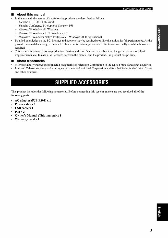
■ About this manual• In this manual, the names of the following products are described as follows.
– Yamaha PJP-100UH: this unit
– Yamaha Conference Microphone Speaker: PJP
– Microsoft® Windows®: Windows
– Microsoft® Windows XP®: Windows XP
– Microsoft® Windows 2000® Professional: Windows 2000 Professional
• Detailed knowledge on the PC, Internet and network may be required to utilize this unit at its full performance. As the
provided manual does not give detailed technical information, please also refer to commercially available books as
required.
• This manual is printed prior to production. Design and specifications are subject to change in part as a result of
improvements, etc. In case of differences between the manual and the product, the product has priority.
■ About trademarks• Microsoft and Windows are registered trademarks of Microsoft Corporation in the United States and other countries.
• Intel and Celeron are trademarks or registered trademarks of Intel Corporation and its subsidiaries in the United States
and other countries.
This product includes the following accessories. Before connecting this system, make sure you received all of the
following parts.
• AC adapter (PJP-PS01) x 1• Power cable x 1• USB cable x 1• Pad x 3• Owner’s Manual (This manual) x 1• Warranty card x 1
SUPPLIED ACCESSORIES
01EN_00_PJP-100UH_UCGB.book Page 3 Thursday, October 19, 2006 9:18 AM
CONTROLS AND FUNCTIONS
4
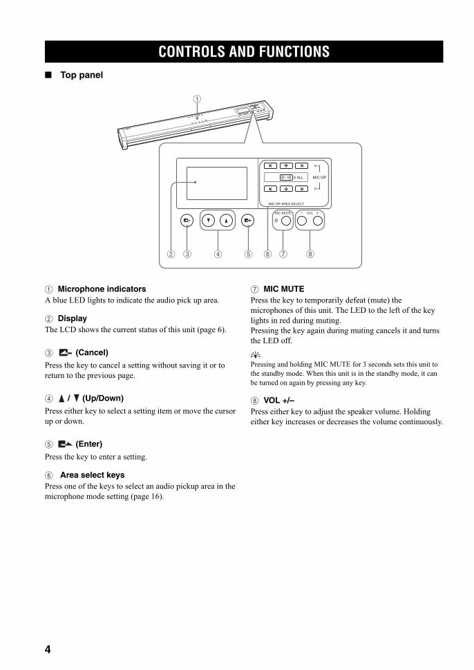
■ Top panel
1 Microphone indicatorsA blue LED lights to indicate the audio pick up area.
2 DisplayThe LCD shows the current status of this unit (page 6).
3 (Cancel)
Press the key to cancel a setting without saving it or to
return to the previous page.
4 / (Up/Down)
Press either key to select a setting item or move the cursor
up or down.
5 (Enter)
Press the key to enter a setting.
6 Area select keysPress one of the keys to select an audio pickup area in the
microphone mode setting (page 16).
7 MIC MUTEPress the key to temporarily defeat (mute) the
microphones of this unit. The LED to the left of the key
lights in red during muting.
Pressing the key again during muting cancels it and turns
the LED off.
y
Pressing and holding MIC MUTE for 3 seconds sets this unit to
the standby mode. When this unit is in the standby mode, it can
be turned on again by pressing any key.
8 VOL +/–Press either key to adjust the speaker volume. Holding
either key increases or decreases the volume continuously.
CONTROLS AND FUNCTIONS
MIC MUTE VOL
2 3
1
4 5 6 7 8
MIC/SP AREA SELECT
MIC/SPALL
01EN_00_PJP-100UH_UCGB.book Page 4 Thursday, October 19, 2006 9:18 AM

5
CONTROLS AND FUNCTIONSIN
TR
OD
UC
TIO
NE
ng
lish
■ Other
1 LabelThe label carries the following information.
• MODEL No.: Model number of this unit.
• SER.: Serial number for use in management/
distinction of this unit.
2 SERIAL terminalReserved for future extension.
3 Arrayed speakers (Bottom panel)Twelve speakers are arrayed on the bottom panel for use
in output of the audio from the unit(s) communicating
with this unit.
4 Arrayed microphones (Side panels)Sixteen microphones are arrayed on each side panel for
use in capturing the voices of the talkers.
5 DC IN 12V terminalConnect the provided AC adapter.
6 AUDIO IN terminalConnect to the line output of an audio equipment or PC.
7 AUDIO OUT terminalConnect to the line input of an audio equipment or PC.
8 USB portConnect a USB cable for connection to a PC.
21 86 75
43
PJP-100UH
PJP-100UH
01EN_00_PJP-100UH_UCGB.book Page 5 Thursday, October 19, 2006 9:18 AM

6
CONTROLS AND FUNCTIONS
■ Display
1 Microphone mode indicatorThe indicator shows the current microphone mode. See
“Selecting the audio pickup area (microphone mode)”
(page 16) for details.
• Zone mode
• Spot mode
• Tracking mode
2 Speaker mode indicatorThe indicator shows the current speaker mode. See
“Configuring the speaker mode” (page 17) for details.
• Monaural mode
• Small Area mode
• Medium Area mode
• Large Area mode
3 Room size indicatorThe indicator shows the audio processing method being
selected according to the room size. See “Configuring the
room size” (page 17) for details.
• Large setting
• Medium setting
• Small setting
4 External input/output indicatorThe indicator shows the current external input/output
setting. See “Configuring the external input/output
setting” (page 18) for details.
• (No indication): External input/output is not set.
• External audio equipment can be connected to
this unit.
• , The PJP can be coupled to this unit (page
14).
5 Operation guideThe names of the currently available operations and their
keys are displayed.
6 Audio monitoring volume indicatorThe indicator shows the audio output level from the
speaker.
7 USB indicatorThe indicator is displayed when a PC is connected to this
unit through a USB cable. The “x” marking is displayed
on the side of the USB indicator when the PC is connected
through audio connection cables or the USB cable is
connected improperly.
:Menu
Volume [10]
1 2 3 4 5 6 7
Example of the initial display
01EN_00_PJP-100UH_UCGB.book Page 6 Thursday, October 19, 2006 9:18 AM

PREPARATION PROCEDURE
7
PR
EPA
RA
TIO
NE
ng
lish
The following preparation steps should be completed before using this unit.
■ Connection of a PC through a USB cable
Step 1: (page 8)Connect this unit to the PC and turn them on.
Step 2: (page 9)Change the settings of the PC connected to this unit.
Step 3: (page 11)Install this unit in the conference room.
■ Connection of a PC through audio connection cables
Step 1: (page 12)Connect this unit to the PC and turn them on.
Step 2: (page 13)Change the settings of the PC connected to this unit.
Step 3: (page 11)Install this unit in the conference room.
y
For the connection method of two PJP-100UH units (coupled
connection), see page 14.
■ Notes on system connectionPlease check the following before proceeding to
preparation.
USB cable (For use in USB connection of PC)Prepare an authorized cable carrying the USB logo.
Audio connection cables (For use in non-USB connection of PC or external equipment)Prepare two audio connection cables (stereo mini-jack
cables).
Specifications of the connected PCThe PC connected to this unit should meet the following
system requirements.
• CPU: Intel Pentium/Celeron processor with 750 MHz
or higher (or equivalent)
• OS: Windows XP Professional, Windows XP Home
Edition or Windows 2000 Professional
• Memory: 128 MB or more (256 MB or more
recommended)
• USB port: USB 1.1 or after (USB 2.0 compatible
recommended)
• Connect this unit and PC directly. Connecting them through a
USB hub may cause problems in operation.
• Audio reproduction may be interrupted depending on the PC
usage situations (workloads or available memory space).
PREPARATION PROCEDURE
Notes
01EN_00_PJP-100UH_UCGB.book Page 7 Thursday, October 19, 2006 9:18 AM

PREPARATION PROCEDURE
8
Follow the procedure below to connect this unit to a PC, and then connect the AC adapter.
1 Connect the USB port of this unit to that of the PC using a USB cable.
y
In addition to the PC connection through a USB cable, this
unit can be connected to a PC or TV conference system
through audio connection cables. For details, see
“Connecting audio connection cables” (page 12).
2 Connect the AC adapter to the DC IN 12V terminal.
3 Connect the power cable to the AC adapter.
4 Connect the power cable to the AC outlet.This unit is turned on and the microphone indicators
light up in sequence.
y
Pressing and holding MIC MUTE for 3 seconds sets this unit to
the standby mode. When this unit is in the standby mode, it can
be turned on again by pressing any key.
Step 1: Connecting this unit
3
4
1
2
To an AC wall outlet
To USB port
01EN_00_PJP-100UH_UCGB.book Page 8 Thursday, October 19, 2006 9:18 AM
PREPARATION PROCEDURE
9
PR
EPA
RA
TIO
NE
ng
lish
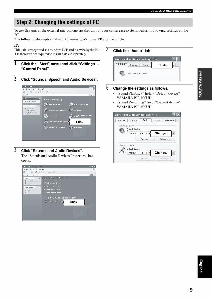
To use this unit as the external microphone/speaker unit of your conference system, perform following settings on the
PC.
The following description takes a PC running Windows XP as an example.
y
This unit is recognized as a standard USB audio device by the PC.
It is therefore not required to install a driver separately.
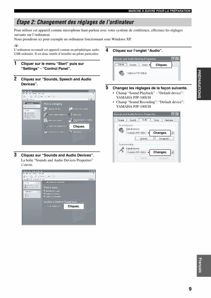
1 Click the “Start” menu and click “Settings” - “Control Panel”.
2 Click “Sounds, Speech and Audio Devices”.
3 Click “Sounds and Audio Devices”.The “Sounds and Audio Devices Properties” box
opens.
4 Click the “Audio” tab.
5 Change the settings as follows.• “Sound Playback” field - “Default device”:
YAMAHA PJP-100UH
• “Sound Recording” field: “Default device”:
YAMAHA PJP-100UH
Step 2: Changing the settings of PC
Click.
Click.
Click.
Change.
Change.
01EN_00_PJP-100UH_UCGB.book Page 9 Thursday, October 19, 2006 9:18 AM
PREPARATION PROCEDURE
10
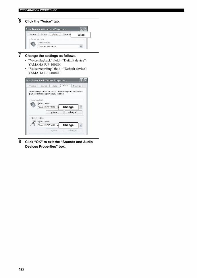
6 Click the “Voice” tab.
7 Change the settings as follows.• “Voice playback” field - “Default device”:
YAMAHA PJP-100UH
• “Voice recording” field - “Default device”:
YAMAHA PJP-100UH
8 Click “OK” to exit the “Sounds and Audio Devices Properties” box.
Click.
Change.
Change.
01EN_00_PJP-100UH_UCGB.book Page 10 Thursday, October 19, 2006 9:18 AM
PREPARATION PROCEDURE
11
PR
EPA
RA
TIO
NE
ng
lish
Follow the procedure below to install this unit in the actual place, such as a conference room.
■ Take the positions of the talkers into considerationTo assure clear conversation by making the most use of the arrayed microphones and speakers, place this unit so that the
talkers sit at the area highlighted in the following figure.
The microphones cannot pick up the audio clearly if the talker sits in one of the positions marked “x” in the figure above.
y
Depending on the using environment, you can configure the setting of the audio pickup area. Refer to “Selecting the audio pickup area
(microphone mode)” (page 16) for details.
■ About the installation environmentThe speakers of this unit are attached in the downward orientation on the bottom panel. Place this unit horizontally on a
desktop without placing any object below this unit. In case you cannot place the unit stably because of the shape of the
desk or other reasons, attach the supplied pads (3 pieces) as illustrated.
Step 3: Installing this unit in the conference room
Note
Front of this unit
Front of this unit
Side ofthis unit
Side of this unit
Display side
Back panel of this unit
1 pad
Concave part
Pad
Rubber cushion
Pad
Attach 1 pad at the center so that the concave part is covered.
Attach 2 pads at the corner so that the rubber cushions are covered.
2 pads
01EN_00_PJP-100UH_UCGB.book Page 11 Thursday, October 19, 2006 9:18 AM

CONNECTION USING AUDIO CONNECTION CABLES
12
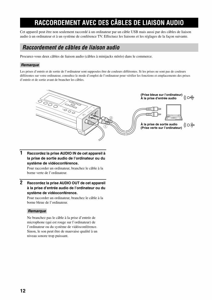
In addition to the PC connection through a USB cable, this unit can be connected to a PC or TV conference system
through audio connection cables. Use the following procedure for the connections and settings.
Prepare two commercially available audio connection cables (stereo mini-jack cables).
The following description assumes that the input/output terminals of the PC are colored for distinction. If your PC does not have the
colored terminals, consult the instruction manual for you PC to confirm the functions and locations of the input/output terminals before
connection.
1 Connect the AUDIO IN jack of this unit to the audio output terminal of the PC or Video Conference system.For connection of a PC, connect the cable to the green
terminal of the PC.
2 Connect the AUDIO OUT jack of this unit to the audio input terminal of the PC or Video Conference system.For connection of a PC, connect the cable to the blue
terminal of the PC.
Do not connect the cable to the microphone input
terminal (which is red with the PC) of the PC or
Video Conference system. Otherwise, an excessive
input signal level may degrade the audio quality.
CONNECTION USING AUDIO CONNECTION CABLES
Connecting audio connection cables
Note
1
2
(Blue terminal on PC) To audio input terminal
To audio output terminal (Green terminal on PC)
Note
01EN_00_PJP-100UH_UCGB.book Page 12 Thursday, October 19, 2006 9:18 AM

CONNECTION USING AUDIO CONNECTION CABLES
13
PR
EPA
RA
TIO
NE
ng
lish
The PC settings should be changed so that the audio input
from this unit to the PC is not output to this unit. In
addition, since the audio of this unit is input from the line
input terminal of the PC, it is also necessary to change the
setting so that the audio input from the line input terminal
is accepted.
1 Open the “Sounds and Audio Devices Properties” box by performing steps 1 to 3 on page 9.
2 Click the “Audio” tab.
3 In the “Sound Playback” field, click “Volume...”.
The “Volume Control” box opens.
4 In the “Line In” field, click “Mute” to check it.
5 In the “Sound recording” field, click “Volume...”.
The “Recording Control” box opens.
6 In the “Line-In” field, click “Select” to check it.
Changing the settings of PC
Click.
Click.
Check.
Click.
Check.
01EN_00_PJP-100UH_UCGB.book Page 13 Thursday, October 19, 2006 9:18 AM
CONNECTION USING AUDIO CONNECTION CABLES
14
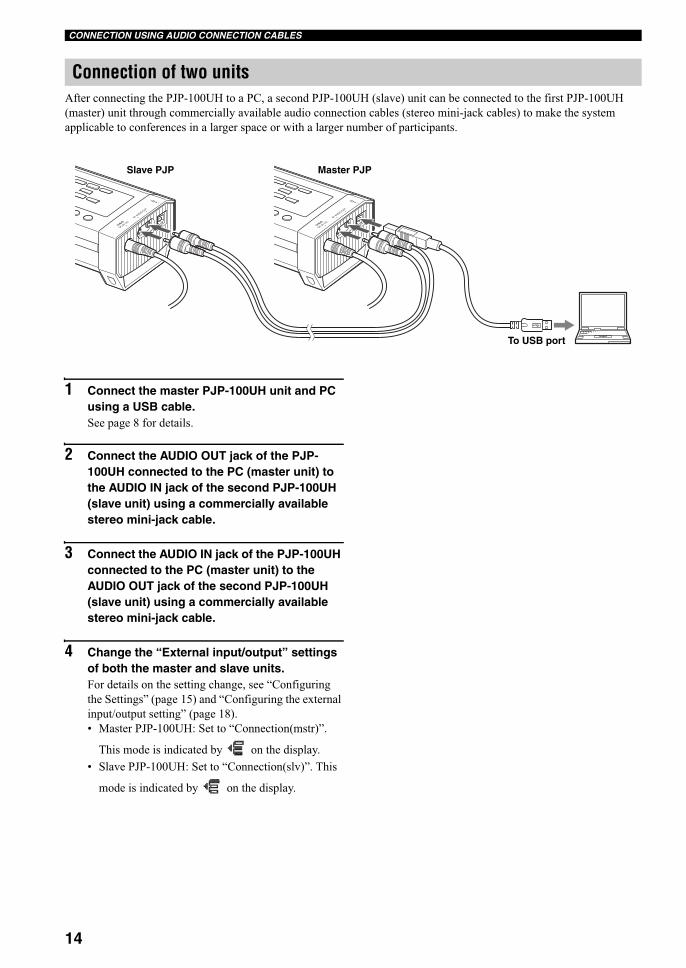
After connecting the PJP-100UH to a PC, a second PJP-100UH (slave) unit can be connected to the first PJP-100UH
(master) unit through commercially available audio connection cables (stereo mini-jack cables) to make the system
applicable to conferences in a larger space or with a larger number of participants.
1 Connect the master PJP-100UH unit and PC using a USB cable.See page 8 for details.
2 Connect the AUDIO OUT jack of the PJP-100UH connected to the PC (master unit) to the AUDIO IN jack of the second PJP-100UH (slave unit) using a commercially available stereo mini-jack cable.
3 Connect the AUDIO IN jack of the PJP-100UH connected to the PC (master unit) to the AUDIO OUT jack of the second PJP-100UH (slave unit) using a commercially available stereo mini-jack cable.
4 Change the “External input/output” settings of both the master and slave units.For details on the setting change, see “Configuring
the Settings” (page 15) and “Configuring the external
input/output setting” (page 18).
• Master PJP-100UH: Set to “Connection(mstr)”.
This mode is indicated by on the display.
• Slave PJP-100UH: Set to “Connection(slv)”. This
mode is indicated by on the display.
Connection of two units
Slave PJP Master PJP
To USB port
01EN_00_PJP-100UH_UCGB.book Page 14 Thursday, October 19, 2006 9:18 AM
15
CO
NFIG
UR
ATION
SE
ng
lish
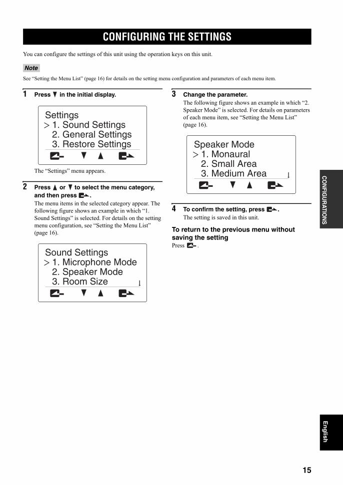
You can configure the settings of this unit using the operation keys on this unit.
See “Setting the Menu List” (page 16) for details on the setting menu configuration and parameters of each menu item.
1 Press in the initial display.
The “Settings” menu appears.
2 Press or to select the menu category, and then press .The menu items in the selected category appear. The
following figure shows an example in which “1.
Sound Settings” is selected. For details on the setting
menu configuration, see “Setting the Menu List”
(page 16).
3 Change the parameter.The following figure shows an example in which “2.
Speaker Mode” is selected. For details on parameters
of each menu item, see “Setting the Menu List”
(page 16).
4 To confirm the setting, press .The setting is saved in this unit.
To return to the previous menu without saving the settingPress .
CONFIGURING THE SETTINGS
Note
3. Restore Settings2. General Settings1. Sound Settings
Settings
3. Room Size2. Speaker Mode1. Microphone Mode
Sound Settings
3. Medium Area2. Small Area1. Monaural
Speaker Mode
01EN_00_PJP-100UH_UCGB.book Page 15 Thursday, October 19, 2006 9:18 AM
SETTING THE MENU LIST
16
This section describes the setting menu items available on this unit.
■ Selecting the audio pickup area (microphone mode)
You can select the audio pickup area of the microphone
during a call. The default setting is “Zone”.
• Zone: Pick up the audio from a large area not only
tracking the audio of the talker. It is suitable for a
relatively quiet environment. Use the area select keys
in the “Microphone Mode” menu to specify the audio
pickup area, and then press . The audio in the area
of the following figure is picked up according to the
pressed keys.
All microphone indicators (blue LED) from the direction
which audio can be picked up light up.
y
• Press to pick up audio from all directions.
• The possible combinations are [ + ], [ + ],
and all areas.
• Spot: Fix the audio pick up area to the front of the
microphone by narrowing the directivity. This mode is
suitable when the number of talkers is limited to one or
two, or when there is equipment that produces noise
such as a projector nearby.
To specify the audio pick up area, use the numeric keys
in the “Microphone Mode” menu. The area shown in
the next figure is enabled or disabled according to the
pressed keys.
Microphone indicators (blue LED) of which direction
audio can be picked up from all light up. This mode
indicated by on the display.
y
The possible combinations are [ + ], [ + ],
[ + ], and all areas.
• Track: The microphone system automatically tracks
and focuses the audio of the talker without fixing the
audio pickup area (only the one talker’s audio can be
picked up at any given time). The audio can be picked
up with narrow directivity so that the noises other than
the taker can be reduced. It is suitable to pick up the
audio clearly in the environment where there are
noises.
SETTING THE MENU LIST
Configuring sound settings
Within 2 m
Within 2 m
Within 2 m
Within 2 m
Within 2 m
Within 2 m
Tracking the talker’s direction automatically
Today...
Next...
01EN_00_PJP-100UH_UCGB.book Page 16 Thursday, October 19, 2006 9:18 AM
17
SETTING THE MENU LISTC
ON
FIGU
RATIO
NS
En
glish
To specify the area to which this feature is available, use
the numeric keys in the “Microphone Mode” menu. The
area shown in the next figure is enabled or disabled
according to the pressed keys.
All microphone indicators (blue LED) from the direction
which audio can be picked up light up.This mode is
indicated by on the display.
y
• Press to pick up audio from all directions.
• You can select multiple areas at the same time.
• You can select areas where the audio pickup feature is not
applied.
Using the keys on this unitIn the initial display, select “Settings” “Sound Settings”
“Microphone Mode”.
y
You can display the “Microphone Mode” menu by holding down
in the initial display or calling display.
■ Configuring the speaker modeYou can select the mode of audio output from the speakers
during call. The default setting is “Divide”.
• Monaural (default): Even during call with more than
one location, the audio from other units is not divided
according to their locations. This mode is indicated by
on the display.
• Small Area: The area where the audio output is heard
is limited to the area shown below (monaural output).
This mode is indicated by on the display.
• Medium Area: The area where the audio output is
heard is limited to the area shown below (monaural
output). This mode is indicated by on the display.
• Large Area: The area where the audio output is heard
is limited to the area shown below (monaural output).
This mode is indicated by on the display.
Using the keys on this unitIn the initial display, select “Settings” “Sound Settings”
“Speaker Mode”.
y
You can display the “Speaker Mode” menu by holding down
in the initial display or calling display.
■ Configuring the room sizeYou can configure this setting depending on the room size
and operating environment. However, you do not need to
change it from “Large” (default setting) normally.
• Large (default): Setting for using this unit in an
ordinary conference room, open space or office. The
communication quality is most stable in this setting.
This setting is indicated by on the display.
• Medium: Select this setting when this unit is used in a
room with large reverberations. This setting reduces
echo heard at the other party locations using the default
“Large” setting. This position is selected when the unit
is used in a room with large reverberations. This setting
is indicated by on the display.
• Small: Select this position when echo is still heard at
the other party location using the “Medium” setting.
This setting is indicated by on the display.
Within 2 m
Within 2 m
01EN_00_PJP-100UH_UCGB.book Page 17 Thursday, October 19, 2006 9:18 AM

18
SETTING THE MENU LIST
• Room Size is a function for reducing echo at the other party
locations. Room Size cannot reduce the echo that is heard from
this unit installed at the local location.
• Positions “Medium” and “Small” can improve the echo
processing capability but lowers the communication quality.
These positions should be selected only when echo is heard at
the other party locations.
Using the keys on this unitIn the initial display or the display during communication,
select “Settings” “Sound Settings” “Room Size”.
■ Configuring the external input/output setting
You need to configure this setting when you connect an
external audio equipment to this unit. The default setting
is “None”.
• None: Disables the external input/output.
• Audio (default): Select this setting when connecting
external audio equipment to this unit.
• Coupled: When coupled connection of two units
(page 14) is used, select this setting on the PJP
connected to the PC through USB (master unit).
Using the keys on this unitIn the initial display, select “Settings” “Sound Settings”
“External I/O”.
■ Adjusting the LCD contrastYou can adjust the contrast of the display by pressing VOL +/–.
Using the keys on this unitIn the initial display, select “Settings” “General
Settings” “LCD Contrast”.
■ Restoring the factory settings of this unit
You can restore the factory settings of this unit. See
“Resetting this Unit” (page 23) for details.
Restoring the factory settings clears all of the settings you made.
Using the keys on this unitIn the initial display, select “Settings” “Restore
Settings”.
Notes Configuring the general setting
Restoring the factory settings
Note
01EN_00_PJP-100UH_UCGB.book Page 18 Thursday, October 19, 2006 9:18 AM
19
CO
NFIG
UR
ATION
SE
ng
lish
You can download the firmware (program to control the functions of this unit) to use the latest features.
To use the revision upgrading function, you should accept the following software licensing agreement.
1 Permission of useThe present Software Licensing Agreement is intended to
allow Yamaha Corporation (hereinafter referred to as
“Yamaha”) to permit you to use the firmware (hereinafter
“this program”) for Yamaha Conference Microphone
Speaker (hereinafter “this product”). You can download
this program after having accepted the terms and
conditions of the present Software Licensing Agreement.
The present Software Licensing Agreement is applicable
to the downloaded copy of this program as well as to its
duplicates produced in accordance with the present
Software Licensing Agreement.
2 Inhibition of redistributionYou are permitted to download this program only for the
purpose of upgrading the functions of this product.
Uploading or posting this program at a website accessible
by the general public is prohibited unless you have
permission from Yamaha.
3 Production of duplicatesYou may only duplicate this program for the purpose of
backup or when upgrading multiple units of this product.
4 Inhibition of decompiling, reverse engineering or disassembling
You may not decompile, reverse-engineer, disassemble,
alter, permit the use of, distribute or create any derivative
works of this program.
5 Limitation of liabilitiesYamaha will not assume any liabilities on the damage to
the customers caused by the present Software Licensing
Agreement.
6 Export controlYou shall comply with all applicable export laws and
regulations of any relevant countries including but not
limited to Japan and your country. You shall not, directly
or indirectly, export or re-export this program except in
compliance with such laws and regulations.
7 Compliance to laws and regulationsThis Software Licensing Agreement should be compliant
to the laws and regulations of Japan and your country, and
should be interpreted in accordance with the laws of
Japan.
UPDATING THE FIRMWARE
Software Licensing Agreement
01EN_00_PJP-100UH_UCGB.book Page 19 Thursday, October 19, 2006 9:18 AM
20
UPDATING THE FIRMWARE
After the latest firmware is downloaded into a PC, use the
PJP Writer software to transfer the firmware to this unit
and upgrade it.
• Once revision upgrading of this unit is started, never perform
any other operation until the upgrading is completed and this
unit is restarted. If upgrading is aborted in the middle, this unit
may become unusable and may need servicing by the
manufacturer.
• When revision upgrading is completed, this unit is restarted
automatically so any communication being held will be shut
down.
• Never turn this unit off or disconnect the USB cable in the
middle of revision upgrading. Otherwise, this unit may become
unusable and may need servicing by the manufacturer. If this
unit became unusable, retry revision upgrading before calling
for service.
■ Downloading the PJP Writer softwareThe PJP Writer software can be downloaded from the PJP
support website.
After accessing the PJP support homepage, go to the
download page and read the explanation on the PJP Writer
software.
Projectphone website:http://www.yamaha.co.jp/english/product/projectphone/
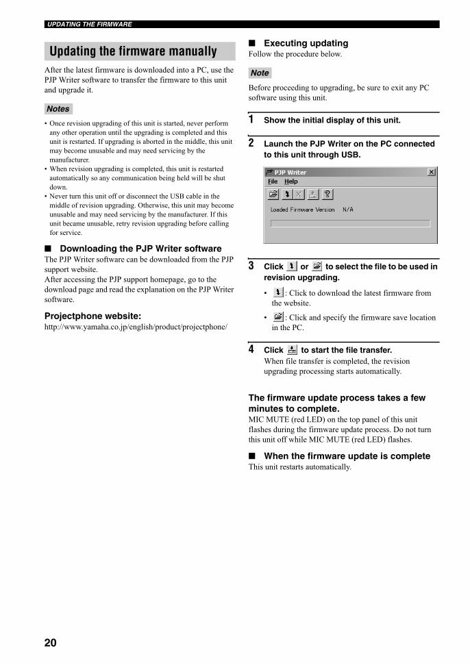
■ Executing updatingFollow the procedure below.
Before proceeding to upgrading, be sure to exit any PC
software using this unit.
1 Show the initial display of this unit.
2 Launch the PJP Writer on the PC connected to this unit through USB.
3 Click or to select the file to be used in revision upgrading.
• : Click to download the latest firmware from
the website.
• : Click and specify the firmware save location
in the PC.
4 Click to start the file transfer.When file transfer is completed, the revision
upgrading processing starts automatically.
The firmware update process takes a few minutes to complete.MIC MUTE (red LED) on the top panel of this unit
flashes during the firmware update process. Do not turn
this unit off while MIC MUTE (red LED) flashes.
■ When the firmware update is completeThis unit restarts automatically.
Updating the firmware manually
Notes
Note
01EN_00_PJP-100UH_UCGB.book Page 20 Thursday, October 19, 2006 9:18 AM
21
AD
DIT
ION
AL
IN
FO
RM
AT
ION
En
glish
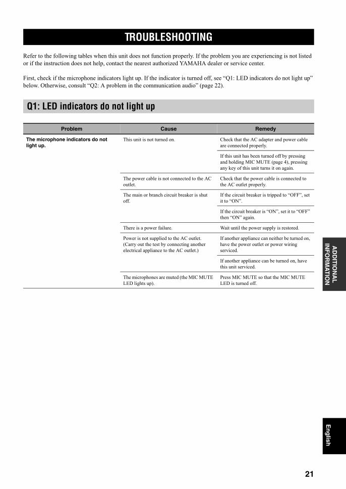
Refer to the following tables when this unit does not function properly. If the problem you are experiencing is not listed
or if the instruction does not help, contact the nearest authorized YAMAHA dealer or service center.
First, check if the microphone indicators light up. If the indicator is turned off, see “Q1: LED indicators do not light up”
below. Otherwise, consult “Q2: A problem in the communication audio” (page 22).
TROUBLESHOOTING
Q1: LED indicators do not light up
Problem Cause Remedy
The microphone indicators do not light up.
This unit is not turned on. Check that the AC adapter and power cable
are connected properly.
If this unit has been turned off by pressing
and holding MIC MUTE (page 4), pressing
any key of this unit turns it on again.
The power cable is not connected to the AC
outlet.
Check that the power cable is connected to
the AC outlet properly.
The main or branch circuit breaker is shut
off.
If the circuit breaker is tripped to “OFF”, set
it to “ON”.
If the circuit breaker is “ON”, set it to “OFF”
then “ON” again.
There is a power failure. Wait until the power supply is restored.
Power is not supplied to the AC outlet.
(Carry out the test by connecting another
electrical appliance to the AC outlet.)
If another appliance can neither be turned on,
have the power outlet or power wiring
serviced.
If another appliance can be turned on, have
this unit serviced.
The microphones are muted (the MIC MUTE
LED lights up).
Press MIC MUTE so that the MIC MUTE
LED is turned off.
01EN_00_PJP-100UH_UCGB.book Page 21 Thursday, October 19, 2006 9:18 AM

22
TROUBLESHOOTING
Q2: A problem in the communication audio
Problem Cause Remedy
The audio from the other unit cannot be heard.
The microphones are muted on the other
unit.
Cancel mute on the other unit.
The audio is interrupted. Audio connection cables are disconnected or
connected improperly.
Connect the audio connection cables
securely.
USB cable is disconnected or connected
improperly.
Connect the USB cable securely.
The USB cable is not connected properly. Check that the USB cable is connected
firmly.
The unit generates feedback noises. The unit is located against a wall. Locate the unit at a certain distance from a
wall.
An object is placed near this unit. Avoid placing an object in front of the
microphones.
This unit is used in a room with high
reverberation.
Place objects with high sound absorbance in
the room by avoiding the positions in front of
the microphones.
Avoid talking at a loud voice to reduce
reverberations.
01EN_00_PJP-100UH_UCGB.book Page 22 Thursday, October 19, 2006 9:18 AM

23
AD
DIT
ION
AL
IN
FO
RM
AT
ION
En
glish
You can restore the factory settings of this unit.
Before restoring the factory settings, note the following.
• All of the settings that have default settings are set to the default
settings.
• Once the factory settings are restored, the previous settings
made by the user cannot be recalled.
• Once revision upgrading is executed, the firmware version of
this unit will not return to the factory-shipped version even
when this unit is reset.
Follow the procedure below to restore the factory settings
using the keys on this unit.
1 Press in the initial display.The “Settings” menu appears.
2 Press , and then press or to select “3. Restore Factory Settings”.
3 Press .The “Restore Settings” menu appears.
4 Select “1. Yes”, and then press .The settings of this unit are reset to the factory
settings, and the “Settings” menu reappears.
To cancel resettingIn step 4, press , or press or to select “2. No”
and then press .
RESETTING THIS UNIT
Notes
MIC MUTE VOL
DC
IN
12V
IN
AU
DIO
OU
T
MIC/SP AREA SELECT
MIC/SPALL
3. Restore Settings2. General Settings1. Sound Settings
Settings
3. Restore Settings2. General Settings1. Sound Settings
Settings
2. No1. Yes
Restore Settings
01EN_00_PJP-100UH_UCGB.book Page 23 Thursday, October 19, 2006 9:18 AM
SPECIFICATIONS
24
General• Dimensions (W x H x D) ...................... 750 mm x 100 mm x 65mm
(29.5 in. x 3.9 in. x 2.6 in.)
• Weight (excl. AC adapter)....................................................... 2.9 kg
(6.4 lbs)
• Power supply........................................ 100 to 240 V AC (50/60 Hz)
• Power consumption .................................................... Approx. 36 W
Operating environment• Ambient temperature ......................................................... 0 to 40°C
(32 to 104 °F)
• Ambient humidity ............................ 20% to 85% (no condensation)
Radio interference standard........................................................................... FCC Part 15 (US)
EN55022 (EU)
USB interfacesUSB 2.0 Full Speed• Compliant to USB audio class and HID class
USB audio format• Record/reproduce channels
• PCM sampling frequency........................................................16 kHz• Quantization ..............................................................................16-bit
When dedicated application is used• PCM sampling frequency........................................................16 kHz• Quantization ..............................................................................16-bit• 3-channel outputs (audio separation by location)
Audio input/output interfaces................................................ Stereo analog input/output (1 each)
• Connectors........................................................................ Mini-jacks
Serial interface.......................................................................................... RS-232C
• Connectors.......................................................................... Mini DIN
Audio• Arrayed microphones (directivity controlled)
• Zone audio pickup function
• Spot audio pickup function
• Microphone auto tracking function
Signal processing• 3CH adaptive echo canceller• Microphone/speaker array control
Accessories• AC adapter (PJP-PS01) x 1• Power cable x 1• USB cable x 1• Owner’s manual (this manual) x 1• Warranty card x 1
*Specifications are subject to change without notice.
SPECIFICATIONS
01EN_00_PJP-100UH_UCGB.book Page 24 Thursday, October 19, 2006 9:18 AM

25
AD
DIT
ION
AL
IN
FO
RM
AT
ION
En
glish
Restore the factory settings before transferring or disposing this unit.
When transferring this unit, be sure to include with the owner’s manual (this manual).
If this unit is transferred or disposed of without restoring the factory settings, information may be abused by a third party.
For instructions on how to restore the factory settings, see “Resetting this Unit” (page 23).
NOTES AN TRANSFERRING/DISPOSING THIS UNIT
Note
01EN_00_PJP-100UH_UCGB.book Page 25 Thursday, October 19, 2006 9:18 AM
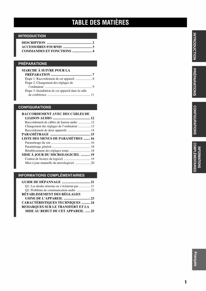
1 Pour utiliser l’appareil au mieux de ses possibilités, lisez attentivement ce mode d’emploi. Conservez-le soigneusement pour référence.
2 Installez cet ensemble dans un endroit frais, bien aéré, sec et propre; ménagez un espace d’au moins 10 cm au dessus, 10 cm à gauche et à droite et 10 cm à l’arrière de cet ensemble – veillez à ce qu’il soit à l’abri de la lumière du soleil, des sources de chaleur, des vibrations, des poussières, de l’humidité et du froid.
3 Placez l’appareil loin des équipements, moteurs et transformateurs électriques, pour éviter les ronflements parasites.
4 N’exposez pas l’appareil à des variations brutales de température, ne le placez pas dans un environnement très humide (par exemple dans une pièce contenant un humidificateur) car cela peut entraîner la condensation d’humidité à l’intérieur de l’appareil qui elle-même peut être responsable de secousse électrique, d’incendie, de dommage à l’appareil ou de blessure corporelle.
5 Evitez d’installer l’appareil dans un endroit où des objets peuvent tomber, ainsi que là où l’appareil pourrait être exposé à des éclaboussures ou des gouttes d’eau. Sur le dessus de l’appareil, ne placez pas:– D’autres appareils qui peuvent endommager la surface de
l’appareil ou provoquer sa décoloration.– Des objets se consumant (par exemple, une bougie) qui
peuvent être responsables d’incendie, de dommage à l’appareil ou de blessure corporelle.
– Des récipients contenant des liquides qui peuvent être à l’origine de secousse électrique ou de dommage à l’appareil.
6 Ne couvrez pas l’appareil d’un journal, d’une nappe, d’un rideau, etc. car cela empêcherait l’évacuation de la chaleur. Toute augmentation de la température intérieure de l’appareil peut être responsable d’incendie, de dommage à l’appareil ou de blessure corporelle.
7 Ne branchez pas la fiche du cordon d’alimentation de l’appareil sur une prise secteur aussi longtemps que tous les raccordements n’ont pas été effectués.
8 Ne pas faire fonctionner l’appareil à l’envers. Il risquerait de chauffer et d’être endommagé.
9 N’exercez aucune force excessive sur les commutateurs, les boutons et les cordons.
10 Pour débrancher la fiche du cordon d’alimentation au niveau de la prise secteur, saisissez la fiche et ne tirez pas sur le cordon.
11 Ne nettoyez pas l’appareil au moyen d’un solvant chimique, ce qui pourrait endommager la finition. Utilisez un chiffon sec et propre.
12 N’alimentez l’appareil qu’à partir de la tension prescrite. Alimenter l’appareil sous une tension plus élevée est dangereux et peut être responsable d’incendie, de dommage à l’appareil ou de blessure corporelle. YAMAHA ne saurait être tenue responsable des dommages résultant de l’alimentation de l’appareil sous une tension autre que celle prescrite.
13 Ne tentez pas de modifier ni de réparer l’appareil. Consultez le service YAMAHA compétent pour toute réparation qui serait requise. Le coffret de l’appareil ne doit jamais être ouvert, quelle que soit la raison.
14 Si vous envisagez de ne pas vous servir de l’appareil pendant une longue période (par exemple, pendant les vacances), débranchez la fiche du cordon d’alimentation au niveau de la prise secteur.
15 Lisez la section intitulée “GUIDE DE DÉPANNAGE” où figurent une liste d’erreurs de manipulation communes avant de conclure que l’appareil présente une anomalie de fonctionnement.
16 Avant de déplacer l’appareil, appuyez 3 secondes sur MIC MUTE pour mettre l’appareil en veille, puis débranchez la fiche du cordon d’alimentation au niveau de la prise secteur.
17 La condensation se forme lorsque la température ambiante change brusquement. En ce cas, débranchez la fiche du cordon d’alimentation et laissez l’appareil reposer.
18 La température de l’appareil peut augmenter en raison d’une utilisation prolongée. En ce cas, coupez l’alimentation de l’appareil et laissez-le au repos pour qu’il refroidisse.
19 Installez cet appareil à proximité de la prise secteur et à un emplacement où la fiche du câble d’alimentation est facilement accessible.
DANGERÀ partir du moment où cet appareil est alimenté par le secteur, n’approchez pas vos yeux de la découpe du tiroir, ni d’ailleurs des autres découpes, dans le dessein d’examiner l’intérieur du coffret.
ATTENTION: VEUILLEZ LIRE CE QUI SUIT AVANT D’UTILISER L’APPAREIL.
Cet appareil n’est pas déconnecté du secteur tant qu’il reste branché à la prise de courant. Il se trouve alors “en veille”. En mode veille, l’appareil consomme une très faible quantité de courant.
AVERTISSEMENTPOUR RÉDUIRE LES RISQUES D’INCENDIE OU DE SECOUSSE ÉLECTRIQUE, N’EXPOSEZ PAS CET APPAREIL À LA PLUIE OU À L’HUMIDITÉ.
AVERTISSEMENTCe produit fait partie des produits de Classe A. Dans un environnement domestique, ce produit peut causer des interférences radio, dans lequel cas l’utilisateur devra prendre les mesures nécessaires.
02FR_00_PJP-100UH_UCGB.book Page 1 Friday, August 25, 2006 3:40 PM
1
PR
ÉPA
RA
TIO
NS
INT
RO
DU
CT
ION
CO
NFIG
UR
ATION
SINFO
RMATIO
NS CO
MPLÉM
ENTAIRIESF
rançais
DESCRIPTION ..................................................... 2ACCESSOIRES FOURNIS .................................. 3COMMANDES ET FONCTIONS ....................... 4
MARCHE À SUIVRE POUR LA PRÉPARATION ................................................ 7Étape 1: Raccordement de cet appareil ..................... 8Étape 2: Changement des réglages de
l’ordinateur ........................................................... 9Étape 3: Installation de cet appareil dans la salle
de conférence ...................................................... 11
RACCORDEMENT AVEC DES CÂBLES DE LIAISON AUDIO ............................................ 12Raccordement de câbles de liaison audio ............... 12Changement des réglages de l’ordinateur ............... 13Raccordement de deux appareils ............................ 14
PARAMÉTRAGE ............................................... 15LISTE DES MENUS DE PARAMÈTRES ........ 16
Paramétrage du son ................................................. 16Paramétrage général ................................................ 18Rétablissement des réglages usine .......................... 18
MISE À JOUR DU MICROLOGICIEL ........... 19Contrat de licence du logiciel ................................. 19Mise à jour manuelle du micrologiciel ................... 20
GUIDE DE DÉPANNAGE ................................. 21Q1: Les diodes témoins ne s’éclairent pas .............. 21Q2: Problème de communication audio ................. 22
RÉTABLISSEMENT DES RÉGLAGES USINE DE L’APPAREIL ............................... 23
CARACTÉRISTIQUES TECHNIQUES .......... 24REMARQUES SUR LE TRANSFERT ET LA
MISE AU REBUT DE CET APPAREIL ...... 25
TABLE DES MATIÈRES
INTRODUCTION
PRÉPARATIONS
CONFIGURATIONS
INFORMATIONS COMPLÉMENTAIRIES
02FR_00_PJP-100UH_UCGB.book Page 1 Friday, August 25, 2006 3:40 PM

DESCRIPTION
2
Ce produit est un module microphones/haut-parleurs qui se raccorde à un système de vidéoconférence ou conférence Web pour être utilisé comme terminal audio.
Raccordement au système de vidéoconférence ou conférence WebCet produit peut être relié à un système de vidéoconférence ou de conférence Web pour être utilisé comme microphone/haut-parleur. En remplaçant l’entrée et la sortie audio de ce système par cet appareil vous pourrez communiquer depuis plusieurs lieux et avec plusieurs partenaires à moindre coût.
Rangée de microphones et de haut-parleurs pour une meilleure restitution des voixLes microphones peuvent déterminer la zone où le son doit être capté selon l’environnement et permettent une conversation nette. De plus, un son net est également retransmis aux participants, dans la mesure où ils se trouvent dans la zone optimale, même lorsque le volume sonore est faible grâce au contrôle de directivité des haut-parleurs.
DESCRIPTION
Réseau Internet ou autre, Réseau d’entreprise LAN,
etc.
Succursale A
Siège social Succursale B
Succursale C
02FR_00_PJP-100UH_UCGB.book Page 2 Friday, August 25, 2006 3:40 PM

3
ACCESSOIRES FOURNISIN
TR
OD
UC
TIO
NF
rançais
■ À propos de ce manuel• Les différents produits sont désignés par les noms suivants dans ce manuel.
– Yamaha PJP-100UH: cet appareil– Microphone Haut-parleur de conférence Yamaha: PJP– Microsoft® Windows®: Windows– Microsoft® Windows XP®: Windows XP– Microsoft® Windows 2000® Professional: Windows 2000 Professional
• Pour profiter de toutes les fonctionnalités de cet appareil, des connaissances approfondies de l’ordinateur, des réseaux Internet, etc. peuvent être nécessaires. Ce manuel ne fournissant pas d’informations détaillés à ce sujet, reportez-vous à la documentation disponible dans le commerce, si nécessaire.
• Ce manuel a été imprimé avant la production. La conception et les spécifications sont susceptibles d’être modifiées en vue de l’amélioration du produit ou pour d’autres raisons. En cas de différences entre le manuel et le produit, la produit prime.
■ À propos des marques commerciales• Microsoft et Windows sont des marques déposées de Microsoft Corporation aux États-Unis et dans d’autres pays.• Intel et Celeron sont des marques commerciales ou des marques déposées de Intel Corporation et de ses succursales
aux États-Unis et dans d’autres pays.
Les accessoires suivants sont livrés avec ce produit. Avant de relier ce système, vérifiez si le coffret contient bien tous lesarticles suivants.
• Adaptateur secteur (PJP-PS01) x 1• Câble d’alimentation x 1• Câble USB x 1• Tampon x 3• Mode d’emploi (Ce manuel) x 1• Carte de garantie x 1
ACCESSOIRES FOURNIS
02FR_00_PJP-100UH_UCGB.book Page 3 Friday, August 25, 2006 3:40 PM

COMMANDES ET FONCTIONS
4
■ Panneau supérieur
1 Témoins de microphoneUn diode bleue s’éclaire pour indiquer la zone de capture du son.
2 AfficheurFournit des informations relatives à l’état de l’appareil (page 6).
3 (Annulation)
Cette touche sert à annuler un réglage sans le sauvegarder et à revenir à la page précédente.
4 / (Haut/Bas)
Ces touches servent à sélectionner un paramètre et à déplacer le curseur vers le haut ou le bas.
5 (Validation)
Cette touche sert à valider un réglage.
6 Touches de sélection de zoneAppuyez sur une de ces touches pour sélectionner une zone de capture du son lors du réglage du mode microphone (page 16).
7 MIC MUTECette touche sert à désactiver temporairement les microphones (couper le son) de cet appareil. La diode à la gauche de cette touche s’éclaire en rouge lorsque le son est coupé.Une seconde pression du doigt sur la touche rétablit le son et éteint la diode.
y
Appuyez 3 secondes sur MIC MUTE pour mettre cet appareil en veille. L’appareil peut être remis sous tension, lorsqu’il est en veille, par une touche quelconque.
8 VOL +/–Ces touches servent à régler le volume des haut-parleurs. Pour augmenter ou réduire le son en continu, il faut maintenir la pression sur l’une ou l’autre touche.
COMMANDES ET FONCTIONS
MIC MUTE VOL
2 3
1
4 5 6 7 8
MIC/SP AREA SELECT
MIC/SPALL
02FR_00_PJP-100UH_UCGB.book Page 4 Friday, August 25, 2006 3:40 PM

5
COMMANDES ET FONCTIONSIN
TR
OD
UC
TIO
NF
rançais
■ Divers
1 ÉtiquetteCette étiquette contient les informations suivantes.• MODEL No.: Numéro de modèle de cet appareil.• SER.: Numéro de série pour la gestion/distinction de
cet appareil.
2 Prise SERIALRéservée à une utilisation future.
3 Rangée de haut-parleurs (Bas du panneau latéral)
Les douze haut-parleurs alignés au bas du panneau latéral restituent le son transmis par le ou les appareils communiquant avec cet appareil.
4 Rangée de microphones (Panneaux latéraux)Les seize microphones alignés sur chaque panneau latéral captent les voix des locuteurs.
5 Prise DC IN 12VCette prise sert à raccorder l’adaptateur secteur fourni.
6 Prise AUDIO INCette prise sert à relier la sortie de ligne d’un appareil audio ou d’un ordinateur.
7 Prise AUDIO OUTCette prise sert à relier l’entrée de ligne d’un appareil audio ou d’un ordinateur.
8 Port USBCe port sert à raccorder un ordinateur par un câble USB.
21 86 75
43
PJP-100UH
PJP-100UH
02FR_00_PJP-100UH_UCGB.book Page 5 Friday, August 25, 2006 3:40 PM
6
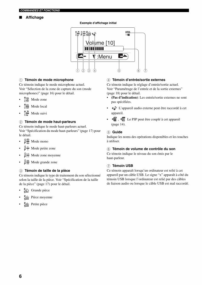
COMMANDES ET FONCTIONS
■ Affichage
1 Témoin de mode microphoneCe témoin indique le mode microphone actuel. Voir “Sélection de la zone de capture du son (mode microphones)” (page 16) pour le détail.
• Mode zone
• Mode local
• Mode suivi
2 Témoin de mode haut-parleursCe témoin indique le mode haut-parleurs actuel. Voir “Spécification du mode haut-parleurs” (page 17) pour le détail.
• Mode mono
• Mode petite zone
• Mode zone moyenne
• Mode grande zone
3 Témoin de taille de la pièceCe témoin indique le type de traitement du son sélectionné selon la taille de la pièce. Voir “Spécification de la taille de la pièce” (page 17) pour le détail.
• Grande pièce
• Pièce moyenne
• Petite pièce
4 Témoin d’entrée/sortie externesCe témoin indique le réglage d’entrée/sortie actuel. Voir “Paramétrage de l’entrée et de la sortie externes” (page 18) pour le détail.• (Pas d’indication): Les entrée/sortie externes ne sont
pas spécifiées.
• L’appareil audio externe peut être raccordé à cet
appareil.
• , Le PJP peut être couplé à cet appareil
(page 14).
5 GuideIndique les noms des opérations disponibles et les touches à utiliser.
6 Témoin de volume de contrôle du sonCe témoin indique le niveau du son émis par le haut-parleur.
7 Témoin USB Ce témoin apparaît lorsqu’un ordinateur est relié à cet appareil par un câble USB. Le signe “x” apparaît à côté du témoin USB lorsque l’ordinateur est relié par des câbles de liaison audio ou lorsque le câble USB est mal raccordé.
:Menu
Volume [10]
1 2 3 4 5 6 7
Exemple d’affichage initial
02FR_00_PJP-100UH_UCGB.book Page 6 Friday, August 25, 2006 3:40 PM
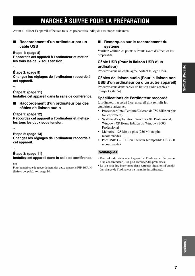
MARCHE À SUIVRE POUR LA PRÉPARATION
7
PR
ÉPA
RA
TIO
NS
Fran
çais
Avant d’utiliser l’appareil effectuez tous les préparatifs indiqués aux étapes suivantes.
■ Raccordement d’un ordinateur par un câble USB
Étape 1: (page 8)Raccordez cet appareil à l’ordinateur et mettez-les tous les deux sous tension.
Étape 2: (page 9)Changez les réglages de l’ordinateur raccordé à cet appareil.
Étape 3: (page 11)Installez cet appareil dans la salle de conférence.
■ Raccordement d’un ordinateur par des câbles de liaison audio
Étape 1: (page 12)Raccordez cet appareil à l’ordinateur et mettez-les tous les deux sous tension.
Étape 2: (page 13)Changez les réglages de l’ordinateur raccordé à cet appareil.
Étape 3: (page 11)Installez cet appareil dans la salle de conférence.
y
Pour la méthode de raccordement des deux appareils PJP-100UH (liaison couplée), voir page 14.
■ Remarques sur le raccordement du système
Veuillez vérifier les points suivants avant d’effectuer les préparatifs.
Câble USB (Pour la liaison USB d’un ordinateur)Procurez-vous un câble agréé portant le logo USB.
Câbles de liaison audio (Pour la liaison non USB d’un ordinateur ou d’un autre appareil)Procurez-vous deux câbles de liaison audio (câbles à minijacks stéréo).
Spécifications de l’ordinateur raccordéL’ordinateur raccordé à cet appareil doit remplir les conditions suivantes.• Processeur: Intel Pentium/Celeron de 750 MHz ou plus
(ou équivalent)• Système d’exploitation: Windows XP Professional,
Windows XP Home Edition ou Windows 2000 Professional
• Mémoire: 128 Mo ou plus (256 Mo ou plus recommandé)
• Port USB: USB 1.1 ou ultérieur (compatible USB 2.0 recommandé)
• Raccordez directement cet appareil et l’ordinateur. L’utilisation d’un concentrateur USB peut entraîner des problèmes.
• Le son peut être interrompu dans certaines situations d’emploi (surcharge de l’ordinateur ou mémoire insuffisante).
MARCHE À SUIVRE POUR LA PRÉPARATION
Remarques
02FR_00_PJP-100UH_UCGB.book Page 7 Friday, August 25, 2006 3:40 PM
MARCHE À SUIVRE POUR LA PRÉPARATION
8
Procédez de la façon suivante pour raccorder cet appareil à un ordinateur, puis raccordez l’adaptateur secteur.
1 Reliez le port USB de cet appareil à celui de l’ordinateur avec un câble USB.
y
Cet appareil peut être non seulement raccordé à un ordinateur par un câble USB mais aussi par des câbles de liaison audio à un ordinateur et à un système de conférence TV. Pour le détail à ce sujet, voir “Raccordement de câbles de liaison audio” (page 12).
2 Raccordez l’adaptateur secteur à la prise DC IN 12V.
3 Raccordez le cordon d’alimentation à l’adaptateur secteur.
4 Raccordez le cordon d’alimentation à la prise secteur.Cet appareil se met sous tension et les témoins de microphones s’éclairent un à un.
y
Appuyez 3 secondes sur MIC MUTE pour mettre cet appareil en veille. L’appareil peut être remis sous tension, lorsqu’il est en veille, par une touche quelconque.
Étape 1: Raccordement de cet appareil
3
4
1
2
À une prise secteur
Au port USB
02FR_00_PJP-100UH_UCGB.book Page 8 Friday, August 25, 2006 3:40 PM
MARCHE À SUIVRE POUR LA PRÉPARATION
9
PR
ÉPA
RA
TIO
NS
Fran
çais
Pour utiliser cet appareil comme microphone haut-parleur avec votre système de conférence, effectuez les réglages suivants sur l’ordinateur.Nous prendrons ici pour exemple un ordinateur fonctionnant sous Windows XP.
y
L’ordinateur reconnaît cet appareil comme un périphérique audio USB ordinaire. Il est donc inutile d’installer un pilote particulier.
1 Cliquer sur le menu “Start” puis sur “Settings” - “Control Panel”.
2 Cliquez sur “Sounds, Speech and Audio Devices”.
3 Cliquez sur “Sounds and Audio Devices”.La boîte “Sounds and Audio Devices Properties” s’ouvre.
4 Cliquez sur l’onglet “Audio”.
5 Changez les réglages de la façon suivante.• Champ “Sound Playback” - “Default device”:
YAMAHA PJP-100UH• Champ “Sound Recording”: “Default device”:
YAMAHA PJP-100UH
Étape 2: Changement des réglages de l’ordinateur
Cliquez.
Cliquez.
Cliquez.
Changez.
Changez.
02FR_00_PJP-100UH_UCGB.book Page 9 Friday, August 25, 2006 3:40 PM

MARCHE À SUIVRE POUR LA PRÉPARATION
10
6 Cliquez sur l’onglet “Voice”.
7 Changez les réglages de la façon suivante.• Champ “Voice playback” - “Default device”:
YAMAHA PJP-100UH• Champ “Voice recording” - “Default device”:
YAMAHA PJP-100UH
8 Cliquez sur “OK” pour sortir de la boîte “Sounds and Audio Devices Properties”.
Cliquez.
Changez.
Changez.
02FR_00_PJP-100UH_UCGB.book Page 10 Friday, August 25, 2006 3:40 PM

MARCHE À SUIVRE POUR LA PRÉPARATION
11
PR
ÉPA
RA
TIO
NS
Fran
çais
Installez cet appareil de la façon suivante dans la salle de conférence, ou la pièce souhaitée.
■ Tenez compte de la position des locuteursPour profiter au maximum de l’effet rayonnant des microphones et des haut-parleurs et pour que la conversation soit la plus nette possible, posez l’appareil de sorte que les locuteurs puissent s’asseoir comme indiqué sur la figure.
Les microphones ne parviennent pas à capter clairement les voix lorsqu’un locuteur se trouve à une des positions indiquées par “x” sur la figure ci-dessus.
y
Vous pouvez paramétrer la zone de capture du son en fonction de l’environnement. Voir “Sélection de la zone de capture du son (mode microphones)” à la page 16 pour de plus amples informations.
■ Environnement recommandéLes haut-parleurs de cet appareil sont orientés vers le bas dans la partie inférieure du panneau. Posez cet appareil à l’horizontale sur un bureau et libérez l’espace en dessous de cet appareil. Si la forme du bureau, par exemple, ne permet d’installer de façon stable l’appareil, fixez les tampons fournis (3), comme sur l’illustration.
Étape 3: Installation de cet appareil dans la salle de conférence
Remarque
Avant de cet appareil
Avant de cet appareil
Côté de cetappareil
Côté de cet appareil
Côté afficheur
Panneau arrière de cet appareil
1 tampon
Partie concave
Tampon
Rondelle de caoutchouc
Tampon
Fixez 1 tampon au centre en recouvrant la partie concave.
Fixez 2 tampons aux coins en recouvrant les rondelles de caoutchouc.
2 tampons
02FR_00_PJP-100UH_UCGB.book Page 11 Friday, August 25, 2006 3:40 PM
RACCORDEMENT AVEC DES CÂBLES DE LIAISON AUDIO
12
Cet appareil peut être non seulement raccordé à un ordinateur par un câble USB mais aussi par des câbles de liaison audio à un ordinateur et à un système de conférence TV. Effectuez les liaisons et les réglages de la façon suivante.
Procurez-vous deux câbles de liaison audio (câbles à minijacks stéréo) dans le commerce.
Les prises d’entrée et de sortie de l’ordinateur sont supposées être de couleurs différentes. Si les prises ne sont pas de couleurs différentes sur votre ordinateur, consultez le mode d’emploi de l’ordinateur pour vérifier les fonctions et emplacements des prises d’entrée et de sortie avant de brancher les câbles.
1 Raccordez la prise AUDIO IN de cet appareil à la prise de sortie audio de l’ordinateur ou du système de vidéoconférence.Pour raccorder un ordinateur, branchez le câble à la borne verte de l’ordinateur.
2 Raccordez la prise AUDIO OUT de cet appareil à la prise d’entrée audio de l’ordinateur ou du système de vidéoconférence.Pour raccorder un ordinateur, branchez le câble à la borne bleue de l’ordinateur.
Ne branchez pas le câble à la prise d’entrée de microphone (qui est rouge sur l’ordinateur) de l’ordinateur ou du système de vidéoconférence. Sinon, le son peut être de mauvaise qualité à un niveau sonore trop puissant.
RACCORDEMENT AVEC DES CÂBLES DE LIAISON AUDIO
Raccordement de câbles de liaison audio
Remarque
1
2
(Prise bleue sur l’ordinateur)À la prise d’entrée audio
À la prise de sortie audio(Prise verte sur l’ordinateur)
Remarque
02FR_00_PJP-100UH_UCGB.book Page 12 Friday, August 25, 2006 3:40 PM
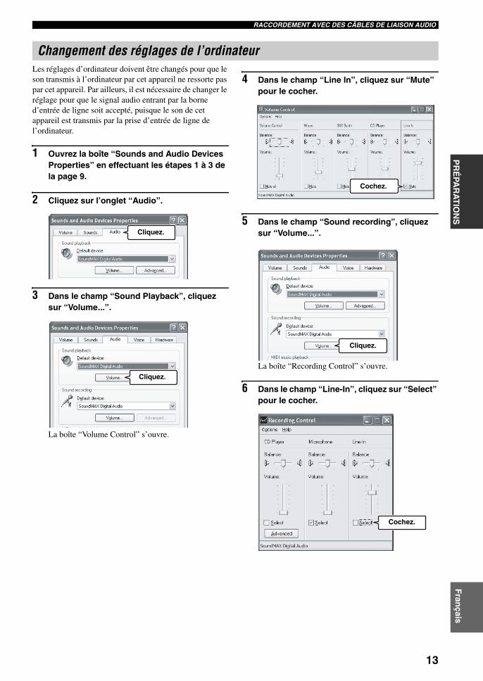
RACCORDEMENT AVEC DES CÂBLES DE LIAISON AUDIO
13
PR
ÉPA
RA
TIO
NS
Fran
çais
Les réglages d’ordinateur doivent être changés pour que le son transmis à l’ordinateur par cet appareil ne ressorte pas par cet appareil. Par ailleurs, il est nécessaire de changer le réglage pour que le signal audio entrant par la borne d’entrée de ligne soit accepté, puisque le son de cet appareil est transmis par la prise d’entrée de ligne de l’ordinateur.
1 Ouvrez la boîte “Sounds and Audio Devices Properties” en effectuant les étapes 1 à 3 de la page 9.
2 Cliquez sur l’onglet “Audio”.
3 Dans le champ “Sound Playback”, cliquez sur “Volume...”.
La boîte “Volume Control” s’ouvre.
4 Dans le champ “Line In”, cliquez sur “Mute” pour le cocher.
5 Dans le champ “Sound recording”, cliquez sur “Volume...”.
La boîte “Recording Control” s’ouvre.
6 Dans le champ “Line-In”, cliquez sur “Select” pour le cocher.
Changement des réglages de l’ordinateur
Cliquez.
Cliquez.
Cochez.
Cliquez.
Cochez.
02FR_00_PJP-100UH_UCGB.book Page 13 Friday, August 25, 2006 3:40 PM

RACCORDEMENT AVEC DES CÂBLES DE LIAISON AUDIO
14
Après avoir relié le PJP-100UH à un ordinateur, vous pouvez raccorder un second PJP-100UH (appareil auxiliaire) au premier PJP-100UH (appareil maître) avec des câbles de liaison audio (câbles à minijacks stéréo) du commerce pour utiliser le système de conférence dans des lieux plus spacieux ou avec un plus grand nombre de participants.
1 Raccordez l’appareil maître PJP-100UH et l’ordinateur à l’aide d’un câble USB.Voir page 8 pour le détail.
2 Reliez la prise AUDIO OUT du PJP-100UH raccordé à l’ordinateur (appareil maître) à la prise AUDIO IN du second PJP-100UH (appareil auxiliaire) à l’aide d’un câble à minijacks stéréo du commerce.
3 Reliez la prise AUDIO IN du PJP-100UH raccordé à l’ordinateur (appareil maître) à la prise AUDIO OUT du second PJP-100UH (appareil auxiliaire) à l’aide d’un câble à minijacks stéréo du commerce.
4 Changez les réglages “External input/output” de l’appareil maître et de l’appareil auxiliaire.Pour le détail sur le changement des réglages, voir “Paramétrage” (page 15) et “Paramétrage de l’entrée et de la sortie externes” (page 18).• Maître PJP-100UH: Réglé sur “Connection(mstr)”.
Ce mode est indiqué par sur l’afficheur.
• Auxiliaire PJP-100UH: Réglé sur “Connection(slv)”.
Ce mode est indiqué par sur l’afficheur.
Raccordement de deux appareils
PJP auxiliaire PJP maître
Au port USB
02FR_00_PJP-100UH_UCGB.book Page 14 Friday, August 25, 2006 3:40 PM

15
CO
NFIG
UR
ATION
SF
rançais
Vous pouvez effectuer les réglages avec les touches d’xploitation de cet appareil.
Voir la “Liste des menus de paramètres” (page 16) pour le détail sur la configuration des menus de paramètres et le réglage des paramètres de chaque élément du menu.
1 Appuyez sur pendant l’affichage initial.
Le menu “Settings” apparaît.
2 Appuyez sur ou pour sélectionner la catégorie de menu, puis appuyez sur .Les éléments dans la catégorie de menu sélectionnée apparaissent. Dans l’exemple suivant “1. Sound Settings” a été sélectionné. Pour le détail sur la configuration des menus de paramètres, voir la “Liste des menus de paramètres” (page 16).
3 Changez le paramètre.Dans l’exemple suivant “2. Speaker Mode” a été sélectionné. Pour le détail sur les paramètres de chaque élément du menu, voir la “Liste des menus de paramètres” (page 16).
4 Pour valider le réglage, appuyez sur .Le réglage est sauvegardé sur cet appareil.
Pour revenir au menu précédent sans sauvegarder le réglageAppuyez sur .
PARAMÉTRAGE
Remarque
3. Restore Settings2. General Settings1. Sound Settings
Settings
3. Room Size2. Speaker Mode1. Microphone Mode
Sound Settings
3. Medium Area2. Small Area1. Monaural
Speaker Mode
02FR_00_PJP-100UH_UCGB.book Page 15 Friday, August 25, 2006 3:40 PM
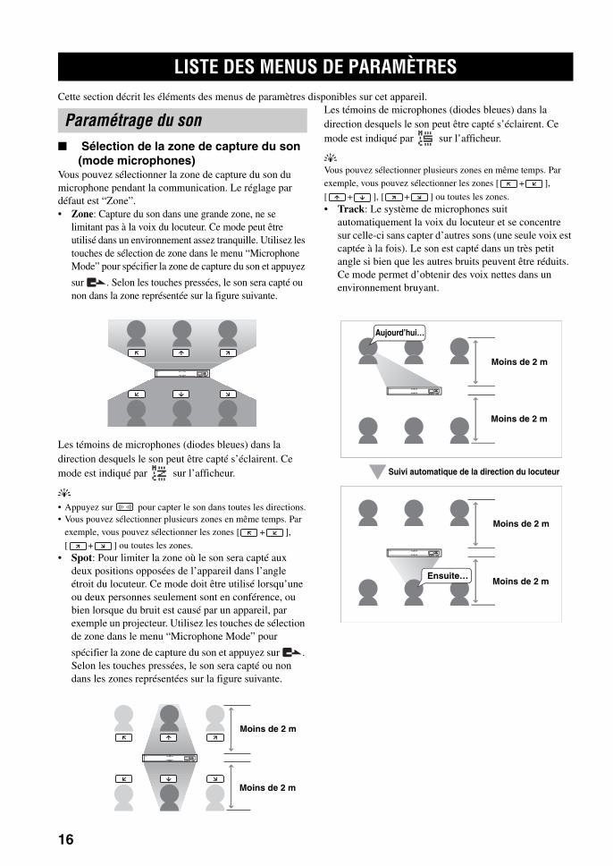
LISTE DES MENUS DE PARAMÈTRES
16
Cette section décrit les éléments des menus de paramètres disponibles sur cet appareil.
■ Sélection de la zone de capture du son (mode microphones)
Vous pouvez sélectionner la zone de capture du son du microphone pendant la communication. Le réglage par défaut est “Zone”.• Zone: Capture du son dans une grande zone, ne se
limitant pas à la voix du locuteur. Ce mode peut être utilisé dans un environnement assez tranquille. Utilisez les touches de sélection de zone dans le menu “Microphone Mode” pour spécifier la zone de capture du son et appuyez
sur . Selon les touches pressées, le son sera capté ou non dans la zone représentée sur la figure suivante.
Les témoins de microphones (diodes bleues) dans la direction desquels le son peut être capté s’éclairent. Ce mode est indiqué par sur l’afficheur.
y
• Appuyez sur pour capter le son dans toutes les directions.• Vous pouvez sélectionner plusieurs zones en même temps. Par
exemple, vous pouvez sélectionner les zones [ + ],
[ + ] ou toutes les zones.• Spot: Pour limiter la zone où le son sera capté aux
deux positions opposées de l’appareil dans l’angle étroit du locuteur. Ce mode doit être utilisé lorsqu’une ou deux personnes seulement sont en conférence, ou bien lorsque du bruit est causé par un appareil, par exemple un projecteur. Utilisez les touches de sélection de zone dans le menu “Microphone Mode” pour
spécifier la zone de capture du son et appuyez sur . Selon les touches pressées, le son sera capté ou non dans les zones représentées sur la figure suivante.
Les témoins de microphones (diodes bleues) dans la direction desquels le son peut être capté s’éclairent. Ce mode est indiqué par sur l’afficheur.
y
Vous pouvez sélectionner plusieurs zones en même temps. Par exemple, vous pouvez sélectionner les zones [ + ],
[ + ], [ + ] ou toutes les zones.• Track: Le système de microphones suit
automatiquement la voix du locuteur et se concentre sur celle-ci sans capter d’autres sons (une seule voix est captée à la fois). Le son est capté dans un très petit angle si bien que les autres bruits peuvent être réduits. Ce mode permet d’obtenir des voix nettes dans un environnement bruyant.
LISTE DES MENUS DE PARAMÈTRES
Paramétrage du son
Moins de 2 m
Moins de 2 m
Moins de 2 m
Moins de 2 m
Moins de 2 m
Moins de 2 m
Suivi automatique de la direction du locuteur
Aujourd’hui…
Ensuite…
02FR_00_PJP-100UH_UCGB.book Page 16 Friday, August 25, 2006 3:40 PM

17
LISTE DES MENUS DE PARAMÈTRESC
ON
FIGU
RATIO
NS
Fran
çais
Pour définir la zone dans laquelle cette fonction agit, utilisez les touches de sélection de zone dans “Microphone Mode”, puis appuyez sur . Selon les touches pressées, le son sera capté ou non dans la zone représentée sur la figure suivante.
Les témoins de microphones (diodes bleues) dans la direction desquels le son peut être capté s’éclairent. Ce mode est indiqué par sur l’afficheur.
y
• Appuyez sur pour capter le son dans toutes les directions.• Vous pouvez sélectionner plusieurs zones en même temps.• Vous pouvez sélectionner des zones où le son n’est pas capté.
Utilisation des touches de cet appareilSur l’affichage initial, sélectionnez “Settings” “Sound Settings” “Microphone Mode”.
y
Vous pouvez afficher le menu “Microphone Mode” en exerçant
une pression continue sur sur l’affichage initial ou sur
l’affichage d’appel.
■ Spécification du mode haut-parleursVous pouvez sélectionner le mode de sortie du son des haut-parleurs pendant la communication. Le réglage par défaut est “Divide”.• Monaural (défaut): Même lors d’une conférence en
plus d’un lieu, le son transmis par les autres appareils ne se divise pas en fonction du nombre de lieux. Ce
mode est indiqué par sur l’afficheur.
• Small Area: La zone d’où provient le son des autres appareils est limitée, comme indiqué ci-dessous (sortie
mono). Ce mode est indiqué par sur l’afficheur.
• Medium Area: La zone d’où provient le son des autres appareils est limitée, comme indiqué ci-dessous (sortie
mono). Ce mode est indiqué par sur l’afficheur.
• Large Area: La zone d’où provient le son des autres appareils est limitée, comme indiqué ci-dessous (sortie
mono). Ce mode est indiqué par sur l’afficheur.
Utilisation des touches de cet appareilSur l’affichage initial, sélectionnez “Settings” “Sound Settings” “Speaker Mode”.
y
Vous pouvez afficher le menu “Speaker Mode” en exerçant une
pression continue sur sur l’affichage initial ou sur
l’affichage d’appel.
■ Spécification de la taille de la pièceCe paramètre peut être réglé en fonction de la taille de la pièce et de l’environnement. Toutefois, pour une pièce “Large” vous n’aurez pas besoin de le changer (réglage par défaut).• Large (défaut): Utilisez ce réglage pour une salle de
conférence ordinaire, dans un espace ou un bureau ouvert. La communication est la plus stable avec ce
réglage. Ce réglage est indiqué par sur l’afficheur.• Medium: Sélectionnez ce réglage si de l’écho gêne la
communication du correspondant avec le réglage par défaut “Large”. Ce réglage doit être sélectionné lorsque l’appareil est utilisé dans une pièce à fortes
réverbérations. Ce réglage est indiqué par sur l’afficheur.
• Small: Sélectionnez ce réglage si de l’écho continue de gêner la communication du correspondant avec le
réglage “Medium”. Ce réglage est indiqué par sur l’afficheur.
Moins de 2 m
Moins de 2 m
02FR_00_PJP-100UH_UCGB.book Page 17 Friday, August 25, 2006 3:40 PM
18
LISTE DES MENUS DE PARAMÈTRES
• La taille de la pièce est le paramètre qui réduit l’écho pouvant apparaître sur la communication du correspondant. Le réglage de la taille de la pièce ne permet pas de réduire l’écho sur l’appareil installé dans la pièce à l’origine de cet écho.
• Les réglages “Medium” et “Small” peuvent réduire l’écho mais réduisent aussi la qualité de la communication. Ces réglages ne devraient être sélectionnés que lorsque de l’écho gêne la communication du correspondant.
Utilisation des touches de cet appareilSur l’affichage initial ou l’affichage apparaîssant pendant la communication, sélectionnez “Settings” “Sound Settings” “Room Size”.
■ Paramétrage de l’entrée et de la sortie externes
Ce paramétrage est nécessaire lorsque vous raccordez un appareil audio à cet appareil. Le réglage par défaut est “None”.• None: Désactive l’entrée et la sortie externes.• Audio (défaut): Sélectionnez ce réglage lorsque vous
raccordez un appareil audio à cet appareil.• Coupled: Lors d’une liaison couplée de deux appareils
(page 14), sélectionnez ce réglage sur le PJP raccordé à l’ordinateur par le port USB (appareil maître).
Utilisation des touches de cet appareilSur l’affichage initial, sélectionnez “Settings” “Sound Settings” “External I/O”.
■ Réglage du contraste de l’afficheurVous pouvez régler le contraste de l’afficheur en appuyant sur VOL +/–.
Utilisation des touches de cet appareilSur l’affichage initial, sélectionnez “Settings” “General Settings” “LCD Contrast”.
■ Rétablissement des réglages usine de cet appareil
Vous pouvez rétablir les réglages usine de cet appareil. Voir “Rétablissement des réglages usine de l’appareil” (page 23) pour le détail.
Lorsque les réglages usine sont rétablis, tous les réglages effectués sont effacés.
Utilisation des touches de cet appareilSur l’affichage initial, sélectionnez “Settings” “Restore Settings”.
Remarques Paramétrage général
Rétablissement des réglages usine
Remarque
02FR_00_PJP-100UH_UCGB.book Page 18 Friday, August 25, 2006 3:40 PM
19
CO
NFIG
UR
ATION
SF
rançais
Vous pouvez télécharger le micrologiciel (programme de commande des fonctions de cet appareil) pour bénéficier des nouvelles caractéristiques.
Pour utiliser les mises à jour, vous devez accepter le contrat de licence du logiciel suivant.
1 Permis d’utilisationPar le présent Contrat de Licence du Logiciel, la Société Yamaha (nommé ci-après “Yamaha”) vous autorise à utiliser le micrologiciel (nommé ci-après “ce programme”) pour le système de Microphone Haut-parleur de conférence Yamaha (nommé ci-après “ce produit”). Vous pouvez télécharger ce programme après avoir accepté les termes et conditions du présent Contrat de Licence du Logiciel.Le Contrat de Licence de Logiciel s’applique à la copie téléchargée de ce programme ainsi qu’à ces duplicata, obtenus conformément au présent contrat.
2 Redistribution interditeVous êtes autorisé à télécharger ce programme seulement pour la mise à jour des fonctions de ce produit. Il est interdit de transmettre ce programme ou de le mettre sur un site Internet accessible à un grande nombre de personnes sans la permission de Yamaha.
3 Création de duplicataVous êtes autorisé à faire des copies de ce programme en vue de la sauvegarde seulement ou de la mise à jour de plus d’un modèle de ce produit.
4 Décompilation, rétrotechnique et désossage interdits
Vous n’êtes pas autorisé à décompiler, reconstituer, démonter, modifier, permettre l’usage de, distribuer ou créer des dérivés de ce programme.
5 Limite de responsabilitéEn aucun cas, même en cas de négligence de sa part, Yamaha ne peut être tenu pour responsable de dommages causés aux clients par le présent Contrat de Licence du Logiciel.
6 Contrôle à l’exportationVous devez vous conformer aux lois et réglementations relatives à l’exportation en vigueur dans les pays concernés, y compris mais sans s’y limiter, au Japon et dans votre pays. Vous n’êtes pas autorisé à exporter ou réexporter, directement ou indirectement, ce programme, si ce n’est conformément aux lois et réglementations.
7 Conformité aux lois et réglementationsCe Contrat de Licence de Logiciel doit être conforme aux lois et aux réglementations du Japon et de votre pays, et doit être interprété en fonction des lois du Japon.
MISE À JOUR DU MICROLOGICIEL
Contrat de licence du logiciel
02FR_00_PJP-100UH_UCGB.book Page 19 Friday, August 25, 2006 3:40 PM

20
MISE À JOUR DU MICROLOGICIEL
Après avoir téléchargé la dernière version du micrologiciel sur un ordinateur, utilisez le logiciel PJP Writer pour transférer le micrologiciel sur cet appareil et faire la mise à jour.
• Pendant la mise à jour du micrologiciel de cet appareil n’effectuez jamais d’autres opérations. Attendez que la mise à jour soit terminée et l’appareil remis en service. Une interruption de la mise à jour peut rendre cet appareil inutilisable et nécessiter une réparation par le fabricant.
• Après la mise à jour, l’appareil se remet automatiquement en service de sorte que toute communication est coupée.
• Ne mettez jamais cet appareil hors service ou ne débranchez pas le câble USB pendant la mise à jour. L’appareil peut devenir inutilisable et devra être réparé par le fabricant. Le cas échéant, essayez de refaire une mise à jour avant d’appeler le service après-vente.
■ Téléchargement du logiciel PJP WriterLe logiciel PJP Writer peut être téléchargé depuis l’assistance du site PJP.Après avoir accédé à la page Assistace PJP, passez à la page de téléchargement et lisez les explications concernant le logiciel PJP Writer.
Site Web Projectphone:http://www.yamaha.co.jp/english/product/projectphone/
■ Exécution de la mise à jourEffectuez les opérations suivantes.
Avant d’effectuer la mise à jour, fermez tous les logiciels utilisant cet appareil sur l’ordinateur.
1 Revenez à l’affichage initial de cet appareil.
2 Lancez le PJP Writer sur l’ordinateur raccordé à cet appareil par la prise USB.
3 Cliquez sur ou pour sélectionner le fichier qui doit être utilisé pour la mise à jour.
• : Cliquez pour télécharger le tout dernier micrologiciel du site Web.
• : Cliquez et spécifiez l’emplacement de sauvegarde du micrologiciel sur l’ordinateur.
4 Cliquez sur pour démarrer le transfert de fichier.Lorsque le transfert est terminé, la mise à jour commence automatiquement.
La mise à jour dure quelques minutes.MIC MUTE (diode rouge) sur le panneau supérieur de l’appareil clignote durant toute la mise à jour. N’éteignez pas cet appareil lorsque MIC MUTE (diode rouge) clignote.
■ Lorsque la mise à jour du micrologiciel est terminée
Cet appareil se remet automatiquement en marche.
Mise à jour manuelle du micrologiciel
Remarques
Remarque
02FR_00_PJP-100UH_UCGB.book Page 20 Friday, August 25, 2006 3:40 PM
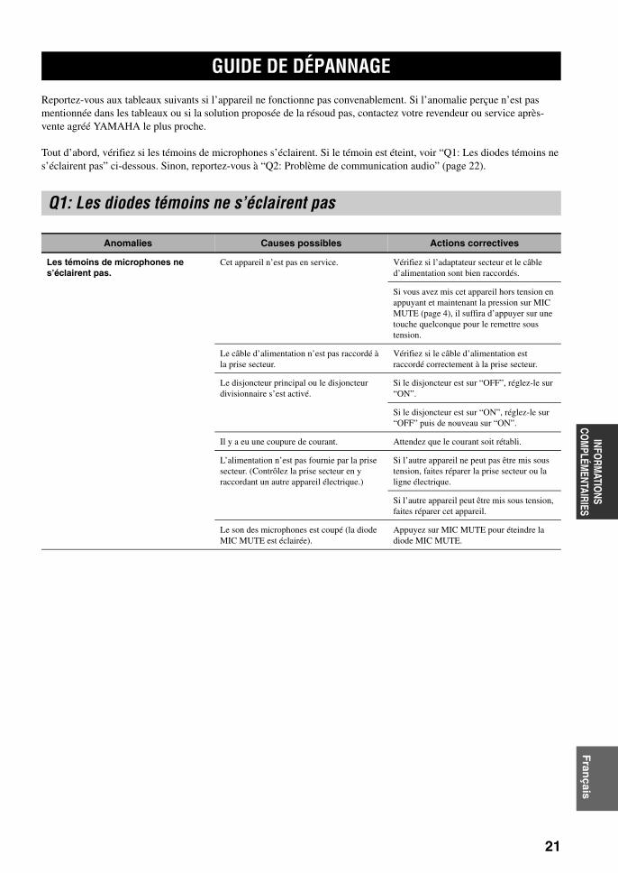
21
INFORM
ATIONS
COM
PLÉMENTAIRIES
Fran
çais
Reportez-vous aux tableaux suivants si l’appareil ne fonctionne pas convenablement. Si l’anomalie perçue n’est pas mentionnée dans les tableaux ou si la solution proposée de la résoud pas, contactez votre revendeur ou service après-vente agréé YAMAHA le plus proche.
Tout d’abord, vérifiez si les témoins de microphones s’éclairent. Si le témoin est éteint, voir “Q1: Les diodes témoins ne s’éclairent pas” ci-dessous. Sinon, reportez-vous à “Q2: Problème de communication audio” (page 22).
GUIDE DE DÉPANNAGE
Q1: Les diodes témoins ne s’éclairent pas
Anomalies Causes possibles Actions correctives
Les témoins de microphones ne s’éclairent pas.
Cet appareil n’est pas en service. Vérifiez si l’adaptateur secteur et le câble d’alimentation sont bien raccordés.
Si vous avez mis cet appareil hors tension en appuyant et maintenant la pression sur MIC MUTE (page 4), il suffira d’appuyer sur une touche quelconque pour le remettre sous tension.
Le câble d’alimentation n’est pas raccordé à la prise secteur.
Vérifiez si le câble d’alimentation est raccordé correctement à la prise secteur.
Le disjoncteur principal ou le disjoncteur divisionnaire s’est activé.
Si le disjoncteur est sur “OFF”, réglez-le sur “ON”.
Si le disjoncteur est sur “ON”, réglez-le sur “OFF” puis de nouveau sur “ON”.
Il y a eu une coupure de courant. Attendez que le courant soit rétabli.
L’alimentation n’est pas fournie par la prise secteur. (Contrôlez la prise secteur en y raccordant un autre appareil électrique.)
Si l’autre appareil ne peut pas être mis sous tension, faites réparer la prise secteur ou la ligne électrique.
Si l’autre appareil peut être mis sous tension, faites réparer cet appareil.
Le son des microphones est coupé (la diode MIC MUTE est éclairée).
Appuyez sur MIC MUTE pour éteindre la diode MIC MUTE.
02FR_00_PJP-100UH_UCGB.book Page 21 Friday, August 25, 2006 3:40 PM

22
GUIDE DE DÉPANNAGE
Q2: Problème de communication audio
Anomalies Causes possibles Actions correctives
Le sonde l’autre appareil n’est pas audible.
Le son des microphones a été coupé sur l’autre appareil.
Rétablissez le son sur l’autre appareil.
Le son est interrompu. Les câbles de liaison audio sont débranchés ou mal branchés.
Branchez correctement les câbles de liaison audio.
Le câble USB est débranché ou mal branché. Branchez correctement le câble USB.
Le câble USB n’est pas branché correctement.
Assurez-vous que le câble USB est branché à fond dans la prise.
Rétroaction acoustique. L’appareil est placé contre un mur. Placez l’appareil à une certaine distance du mur.
Un objet se trouve près de l’appareil. Évitez de placer un objet devant les microphones.
Cet appareil est utilisé dans une pièce causant une forte réverbération.
Posez des objets absorbant le son dans la pièce mais évitez de les poser devant les microphones.
Évitez de parler très fort pour réduire les révervérations.
02FR_00_PJP-100UH_UCGB.book Page 22 Friday, August 25, 2006 3:40 PM
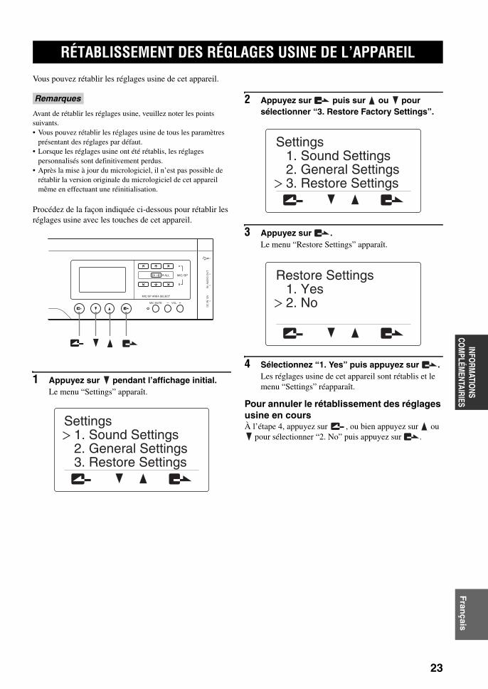
23
INFORM
ATIONS
COM
PLÉMENTAIRIES
Fran
çais
Vous pouvez rétablir les réglages usine de cet appareil.
Avant de rétablir les réglages usine, veuillez noter les points suivants.• Vous pouvez rétablir les réglages usine de tous les paramètres
présentant des réglages par défaut.• Lorsque les réglages usine ont été rétablis, les réglages
personnalisés sont definitivement perdus.• Après la mise à jour du micrologiciel, il n’est pas possible de
rétablir la version originale du micrologiciel de cet appareil même en effectuant une réinitialisation.
Procédez de la façon indiquée ci-dessous pour rétablir les réglages usine avec les touches de cet appareil.
1 Appuyez sur pendant l’affichage initial.Le menu “Settings” apparaît.
2 Appuyez sur puis sur ou pour sélectionner “3. Restore Factory Settings”.
3 Appuyez sur .Le menu “Restore Settings” apparaît.
4 Sélectionnez “1. Yes” puis appuyez sur .Les réglages usine de cet appareil sont rétablis et le menu “Settings” réapparaît.
Pour annuler le rétablissement des réglages usine en coursÀ l’étape 4, appuyez sur , ou bien appuyez sur ou
pour sélectionner “2. No” puis appuyez sur .
RÉTABLISSEMENT DES RÉGLAGES USINE DE L’APPAREIL
Remarques
MIC MUTE VOL
DC
IN
12V
IN
AU
DIO
OU
T
MIC/SP AREA SELECT
MIC/SPALL
3. Restore Settings2. General Settings1. Sound Settings
Settings
3. Restore Settings2. General Settings1. Sound Settings
Settings
2. No1. Yes
Restore Settings
02FR_00_PJP-100UH_UCGB.book Page 23 Friday, August 25, 2006 3:40 PM

CARACTÉRISTIQUES TECHNIQUES
24
Généralités• Dimensions (L x H x P) ....................... 750 mm x 100 mm x 65 mm • Poids (sans l’adaptateur secteur)............................................. 2,9 kg• Alimentation ......................................... 100 à 240 V CA (50/60 Hz)• Consommation ............................................................ Approx. 36 W
Environnement fonctionnel• Température ambiante ........................................................ 0 à 40°C• Humidité ambiante .......................... 20% à 85% (sans condensation)
Norme relative aux interférences radio.............................................................. Section 15 de la FCC (US)
EN55022 (EU)
Interfaces USBVitesse rapide USB 2.0• Conforme à la classe audio USB et à la classe HIDFormat audio USB• Enregistrement/reproduction des voies• Fréquence d’échantillonnage PCM........................................ 16 kHz• Quantification.......................................................................... 16 bitsQuand l’application appropriée est utilisée• Fréquence d’échantillonnage PCM........................................ 16 kHz• Quantification.......................................................................... 16 bits• Sorties 3 voies (séparation des voies selon le lieu)
Interfaces d’entrée/sortie audio....................................Entrée/sortie analogique stéréo (1 chacune)
• Connecteurs...................................................................... Mini-jacks
Interface série.......................................................................................... RS-232C
• Connecteurs........................................................................ Mini DIN
Audio• Rangée de microphones (contrôle de la directivité)• Fonction de capture du son selon la zone• Fonction de capture du son selon un point• Fonction de suivi automatique du son
Traitement du signal• Annulation adaptive de l’écho 3voies• Contrôle de la rangée de microphones/haut-parleurs
Accessoires• Adaptateur secteur (PJP-PS01) x 1• Câble d’alimentation x 1• Câble USB x 1• Mode d’emploi (Ce manuel) x 1• Carte de garantie x 1
* Les caractéristiques techniques peuvent être modifiées sans avis préalable.
CARACTÉRISTIQUES TECHNIQUES
02FR_00_PJP-100UH_UCGB.book Page 24 Friday, August 25, 2006 3:40 PM
25
INFORM
ATIONS
COM
PLÉMENTAIRIES
Fran
çais
Rétablissez les réglages usine avant de transférer cet appareil à quelqu’un ou avant de le mettre au rebut.
Lorsque vous transférez cet appareil à quelqu’un, n’oubliez pas de donner aussi le mode d’emploi (ce manuel).
Ces informations pourraient être utilisées de façon malveillante par un tiers si elles ne sont pas effacées avant le transfert ou la mise au rebut.Pour le détail sur le rétablissement des réglages usine, voir “Rétablissement des réglages usine de l’appareil” (page 23).
REMARQUES SUR LE TRANSFERT ET LA MISE AU REBUT DE CET APPAREIL
Remarque
02FR_00_PJP-100UH_UCGB.book Page 25 Friday, August 25, 2006 3:40 PM
1 Um optimales Leistungsvermögen sicherzustellen, lesen Sie bitte die Anleitung aufmerksam durch. Bewahren Sie die Anleitung danach für spätere Nachschlagzwecke sorgfältig auf.
2 Installieren Sie dieses Gerät an einem gut belüfteten, trockenen, sauberen Ort mit einem Abstand von mindestens 10 cm an der Oberseite, 10 cm an der linken und rechten Seite sowie 10 cm an der Rückseite des Geräts, entfernt von direktem Sonnenlicht, Wärmequellen, Erschütterungen, Staub und/oder Feuchtigkeit.
3 Stellen Sie dieses Gerät entfernt von anderen elektrischen Haushaltgeräten, Motoren oder Transformatoren auf, um Brummgeräusche zu vermeiden.
4 Setzen Sie dieses Gerät keinen plötzlichen Temperaturänderungen von kalt auf warm aus, und stellen Sie dieses Gerät nicht an Orten mit hoher Luftfeuchtigkeit auf (z.B. in Räumen mit Luftbefeuchtern), um Kondensation im Inneren des Gerätes zu vermeiden, da es anderenfalls zu elektrischen Schlägen, Feuer, Beschädigung dieses Gerätes und/oder zu Verletzungen kommen kann.
5 Vermeiden Sie die Aufstellung dieses Gerätes an Orten, an welchen Fremdkörper in das Gerät fallen können bzw. an welchen Flüssigkeiten auf das Gerät verschüttet werden können. Stellen Sie auf der Oberseite des Gerätes niemals folgendes auf:– Andere Komponenten, da diese Beschädigung und/oder
Verfärbung der Oberfläche dieses Gerätes verursachen können.
– Brennende Objekte (z.B. Kerzen), da diese Feuer, Beschädigung des Gerätes und/oder persönliche Verletzungen verursachen können.
– Mit Flüssigkeiten gefüllte Behälter, da diese umfallen und die Flüssigkeit auf das Gerät verschütten können, wodurch es zu elektrischen Schlägen für den Anwender und/oder zu Beschädigung des Gerätes kommen kann.
6 Decken Sie dieses Gerät niemals mit Zeitungen, Tischdecken, Vorhängen usw. ab, damit die Wärmeabfuhr nicht behindert wird. Falls die Temperatur im Inneren des Gerätes ansteigt, kann es zu Feuer, Beschädigung des Gerätes und/oder zu Verletzungen kommen.
7 Schließen Sie dieses Gerät erst an eine Wandsteckdose an, nachdem alle anderen Anschlüsse ausgeführt wurden.
8 Stellen Sie dieses Gerät niemals mit der Unterseite nach oben auf, da es sonst beim Betrieb zu Überhitzung mit möglichen Beschädigungen kommen kann.
9 Wenden Sie niemals Gewalt bei der Bedienung der Schalter, Knöpfe und/oder Kabel an.
10 Wenn Sie das Netzkabel von der Wandsteckdose abtrennen, fassen Sie immer den Netzstecker an; ziehen Sie niemals an dem Kabel.
11 Reinigen Sie dieses Gerät niemals mit chemisch behandelten Tüchern; anderenfalls kann das Finish beschädigt werden. Verwenden Sie ein reines, trockenes Tuch.
12 Verwenden Sie nur die für dieses Gerät vorgeschriebene Netzspannung. Falls Sie eine höhere als die vorgeschriebene Netzspannung verwenden, kann es zu Feuer, Beschädigung dieses Gerätes und/oder zu Verletzungen kommen. YAMAHA kann nicht verantwortlich gemacht werden für Schäden, die auf die Verwendung dieses Gerätes mit einer anderen als der vorgeschriebenen Spannung zurückzuführen sind.
13 Versuchen Sie niemals ein Modifizieren oder Ändern dieses Gerätes. Falls eine Wartung erforderlich ist, wenden Sie sich bitte an einen YAMAHA-Kundendienst. Das Gehäuse sollte niemals selbst geöffnet werden.
14 Falls Sie das Gerät für längere Zeit nicht verwenden (z.B. während der Ferien), ziehen Sie den Netzstecker von der Netzdose ab.
15 Lesen Sie unbedingt den Abschnitt „STÖRUNGSBESEITIGUNG“ durch, um übliche Bedienungsfehler zu berichtigen, bevor Sie auf eine Störung des Gerätes schließen.
16 Vor dem Transportieren dieses Geräts halten Sie MIC MUTE 3 Sekunden lang gedrückt, um das Gerät auf den Bereitschaftsmodus zu schalten, und ziehen Sie den Netzstecker von der Netzsteckdose ab.
17 Es kommt zu Kondensatbildung, wenn die Umgebungstemperatur plötzlich ändert. Ziehen Sie den Netzstecker von der Netzdose ab, und lassen Sie das Gerät ruhen.
18 Falls Sie das Gerät für längere Zeit in Betrieb halten, kann sich das Gerät erwärmen. Schalten Sie die Stromversorgung aus, und lassen Sie danach das Gerät abkühlen.
19 Stellen Sie dieses Gerät in der Nähe der Steckdose und so auf, dass der Netzstecker gut zugänglich ist.
GEFAHRWenn dieses Gerät an eine Netzdose angeschlossen ist, blicken Sie niemals in die Öffnung der Disc-Schublade oder in andere Öffnungen.
VORSICHT: VOR DER BEDIENUNG DIESES GERÄTES DURCHLESEN.
Dieses Gerät ist nicht vom Netz abgetrennt, so lange der Netzstecker an eine Netzdose angeschlossen ist, auch wenn das Gerät selbst ausgeschaltet wurde. Dieser Status wird als Bereitschaftsmodus bezeichnet. Auch in diesem Status weist das Gerät einen geringen Stromberbrauch auf.
WARNUNGUM DIE GEFAHR EINES FEUERS ODER EINES ELEKTROSCHOCKS ZU VERMEIDEN, DARF DAS GERÄT WEDER REGEN NOCH FEUCHTIGKEIT AUSGESETZT WERDEN.
WARNUNGDies ist ein Produkt der Klasse A. In Wohngebieten kann dieses Produkt Störungen des Rundfunk- und Fernsehempfangs verursachen; in diesem Fall kann von Benutzer verlangt werden, angemessene Abhilfemaßnahmen zu ergreifen.
1
VO
RB
ER
EIT
UN
GE
INL
EIT
UN
GK
ON
FIGU
RATIO
NE
NZU
SÄ
TZL
ICH
E
INF
OR
MA
TIO
NE
ND
eutsch
MERKMALE ......................................................... 2MITGELIEFERTES ZUBEHÖR ........................ 3BEDIENUNGSELEMENTE UND
IHRE FUNKTIONEN ....................................... 4
VORBEREITUNGSSCHRITTE ......................... 7Schritt 1: Anschließen dieses Gerätes ....................... 8Schritt 2: Ändern der Einstellungen des PCs ............ 9Schritt 3: Installieren dieses Geräts im
Konferenzraum ................................................... 11
VERBINDUNG MIT AUDIO-VERBINDUNGSKABELN .............. 12Anschließen von Audio-Verbindungskabeln .......... 12Ändern der Einstellungen des PCs ......................... 13Verbindung von zwei Einheiten ............................. 14
KONFIGURIEREN DER EINSTELLUNGEN ......................................... 15
EINSTELLMENÜ-LISTE .................................. 16Konfigurieren der Klang-Einstellungen ................. 16Konfigurieren der generellen Einstellung ............... 18Rücksetzen auf werkseitige Einstellungen ............. 18
AKTUALISIEREN DER FIRMWARE ............ 19Software-Lizenzvereinbarung ................................. 19Manuelles Aktualisieren der Firmware .................. 20
STÖRUNGSBESEITIGUNG ............................. 21Q1: LED-Anzeigen leuchten nicht auf ................... 21Q2: Ein Problem im Kommunikationston .............. 22
RÜCKSETZEN DES GERÄTS ......................... 23TECHNISCHE DATEN ..................................... 24HINWEISE ZUR WEITERGABE/
ENTSORGE DIESES GERÄTS .................... 25
INHALTSVERZEICHNIS
EINLEITUNG
VORBEREITUNG
KONFIGURATIONEN
ZUSÄTZLICHE INFORMATIONEN
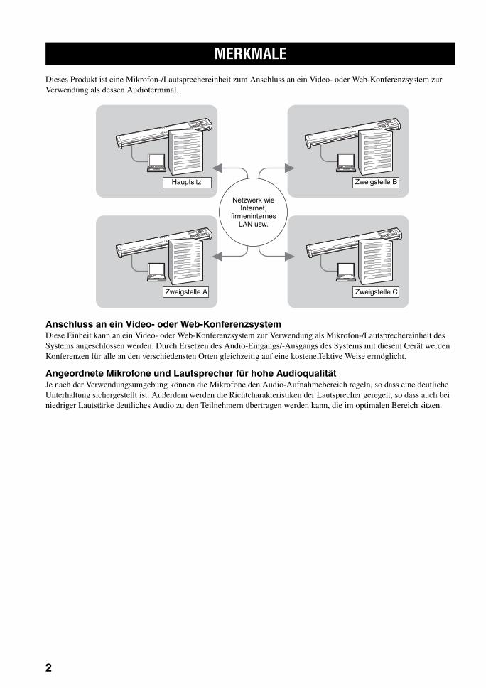
MERKMALE
2
Dieses Produkt ist eine Mikrofon-/Lautsprechereinheit zum Anschluss an ein Video- oder Web-Konferenzsystem zur Verwendung als dessen Audioterminal.
Anschluss an ein Video- oder Web-KonferenzsystemDiese Einheit kann an ein Video- oder Web-Konferenzsystem zur Verwendung als Mikrofon-/Lautsprechereinheit des Systems angeschlossen werden. Durch Ersetzen des Audio-Eingangs/-Ausgangs des Systems mit diesem Gerät werden Konferenzen für alle an den verschiedensten Orten gleichzeitig auf eine kosteneffektive Weise ermöglicht.
Angeordnete Mikrofone und Lautsprecher für hohe AudioqualitätJe nach der Verwendungsumgebung können die Mikrofone den Audio-Aufnahmebereich regeln, so dass eine deutliche Unterhaltung sichergestellt ist. Außerdem werden die Richtcharakteristiken der Lautsprecher geregelt, so dass auch bei niedriger Lautstärke deutliches Audio zu den Teilnehmern übertragen werden kann, die im optimalen Bereich sitzen.
MERKMALE
Netzwerk wie Internet,
firmeninternes LAN usw.
Zweigstelle A
Hauptsitz Zweigstelle B
Zweigstelle C
3
MITGELIEFERTES ZUBEHÖRE
INL
EIT
UN
GD
eutsch
■ Über diese Anleitung• In dieser Anleitung werden die Namen der folgenden Produkte wie folgt beschrieben.
– Yamaha PJP-100UH: dieses Gerät– Yamaha Konferenzmikrofon-Lautsprecher: PJP– Microsoft® Windows®: Windows– Microsoft® Windows XP®: Windows XP– Microsoft® Windows 2000® Professional: Windows 2000 Professional
• Detailkenntnisse über den PC, das Internet und Netzwerk können erforderlich sein, um alle Möglichkeiten dieses Geräts voll auszunutzen. Da die mitgelieferte Anleitung keine detaillierte technische Information enthält, greifen Sie nach Bedarf auch auf im Handel erhältliche Fachliteratur zurück.
• Diese Anleitung wurde vor der Produktion gedruckt. Änderungen des Designs und der technischen Daten im Sinne ständiger Verbesserungen usw. vorbehalten. Im Falle einer Differenz zwischen der Anleitung und dem Produkt hat Produkt Priorität.
■ Über Warenzeichen• Microsoft und Windows sind eingetragene Warenzeichen der Microsoft Corporation in den USA und anderen
Ländern.• Intel und Celeron sind eingetragene Warenzeichen der Intel Corporation und ihrer Tochtergesellschaften in den USA
und anderen Ländern.
Dieses Produkt wird mit den folgenden Zubehörteilen geliefert. Überprüfen Sie vor Anschließen des Systems, dass Sie alle der folgenden Teile erhalten haben.
• Netzteil (PJP-PS01) x 1• Netzkabel x 1• USB-Kabel x 1• Polster x 3• Benutzerhandbuch (diese Anleitung) x 1• Garantiekarte x 1
MITGELIEFERTES ZUBEHÖR

BEDIENUNGSELEMENTE UND IHRE FUNKTIONEN
4
■ Oberseitenplatte
1 MikrofonanzeigenEine blaue LED leuchtet auf, um den Audio-Empfangsbereich anzuzeigen.
2 DisplayDas LCD zeigt Informationen über den aktuellen Betriebsstatus dieses Gerätes an (Seite 6).
3 (Abbrechen)
Drücken Sie diese Taste, um eine Einstellung abzubrechen, ohne sie zu speichern, oder zur vorherigen Seite zurückzugehen.
4 / (Auf/Ab)
Drücken Sie eine der Tasten zum Wählen eines Einstellpunkts oder um den Cursor auf oder ab zu bewegen.
5 (Eingeben)
Drücken Sie die Taste, um eine Einstellung einzugeben.
6 GebietswahltastenDrücken Sie eine der Tasten zur Wahl eines Audio-Aufnahmebereichs in der Mikrofonmodus-Einstellung (Seite 16).
7 MIC MUTEDrücken Sie die Taste, um die Mikrofone dieses Gerät kurz zu deaktivieren (stummzuschalten). Die LED links von der Taste leuchtet während der Stummschaltung rot auf.Durch erneutes Drücken der Taste während der Stummschaltung wird die Funktion deaktiviert und die LED ausgeschaltet.
yIndem Sie MIC MUTE für 3 Sekunden gedrückt halten, wird dieses Gerät auf den Bereitschaftsmodus geschaltet. Wenn dieses Gerät im Bereitschaftsmodus ist, kann es durch Drücken einer beliebigen Taste wieder eingeschaltet werden.
8 VOL +/–Drücken Sie eine der Tasten, um die Lautsprecherlautstärke einzustellen. Indem eine der Tasten gedrückt gehalten wird, wird die Lautstärke kontinuierlich höher oder niedriger gestellt.
BEDIENUNGSELEMENTE UND IHRE FUNKTIONEN
MIC MUTE VOL
2 3
1
4 5 6 7 8
MIC/SP AREA SELECT
MIC/SPALL
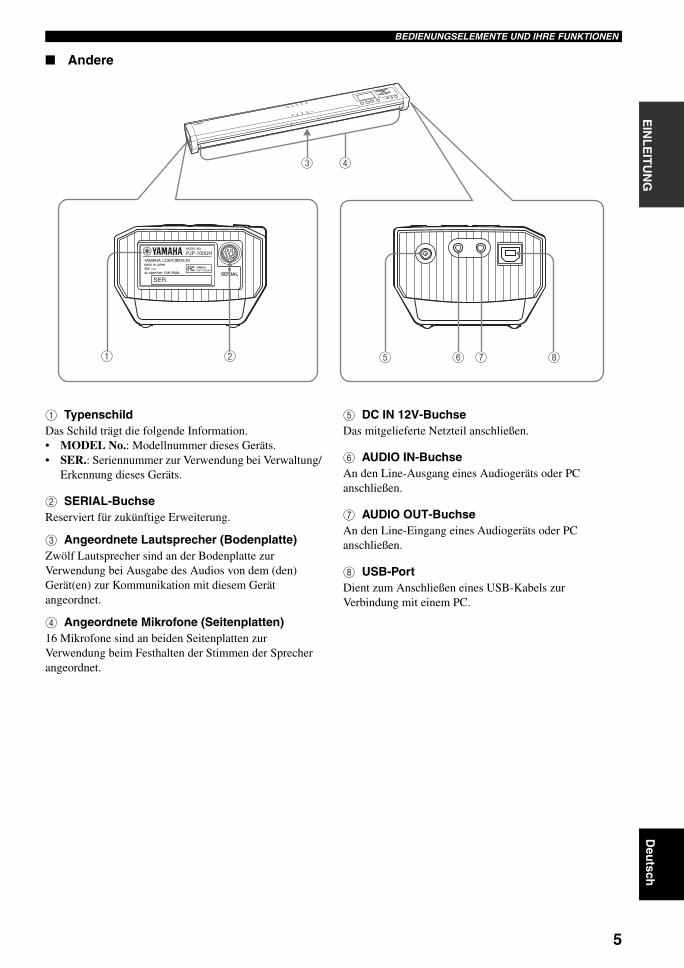
5
BEDIENUNGSELEMENTE UND IHRE FUNKTIONENE
INL
EIT
UN
GD
eutsch
■ Andere
1 TypenschildDas Schild trägt die folgende Information.• MODEL No.: Modellnummer dieses Geräts.• SER.: Seriennummer zur Verwendung bei Verwaltung/
Erkennung dieses Geräts.
2 SERIAL-BuchseReserviert für zukünftige Erweiterung.
3 Angeordnete Lautsprecher (Bodenplatte)Zwölf Lautsprecher sind an der Bodenplatte zur Verwendung bei Ausgabe des Audios von dem (den) Gerät(en) zur Kommunikation mit diesem Gerät angeordnet.
4 Angeordnete Mikrofone (Seitenplatten)16 Mikrofone sind an beiden Seitenplatten zur Verwendung beim Festhalten der Stimmen der Sprecher angeordnet.
5 DC IN 12V-BuchseDas mitgelieferte Netzteil anschließen.
6 AUDIO IN-BuchseAn den Line-Ausgang eines Audiogeräts oder PC anschließen.
7 AUDIO OUT-BuchseAn den Line-Eingang eines Audiogeräts oder PC anschließen.
8 USB-PortDient zum Anschließen eines USB-Kabels zur Verbindung mit einem PC.
21 86 75
43
PJP-100UH
PJP-100UH
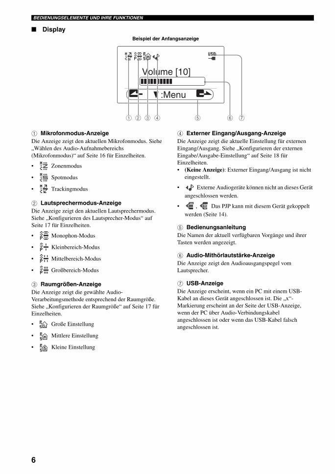
6
BEDIENUNGSELEMENTE UND IHRE FUNKTIONEN
■ Display
1 Mikrofonmodus-AnzeigeDie Anzeige zeigt den aktuellen Mikrofonmodus. Siehe „Wählen des Audio-Aufnahmebereichs (Mikrofonmodus)“ auf Seite 16 für Einzelheiten.
• Zonenmodus
• Spotmodus
• Trackingmodus
2 Lautsprechermodus-AnzeigeDie Anzeige zeigt den aktuellen Lautsprechermodus. Siehe „Konfigurieren des Lautsprecher-Modus“ auf Seite 17 für Einzelheiten.
• Monophon-Modus
• Kleinbereich-Modus
• Mittelbereich-Modus
• Großbereich-Modus
3 Raumgrößen-AnzeigeDie Anzeige zeigt die gewählte Audio-Verarbeitungsmethode entsprechend der Raumgröße. Siehe „Konfigurieren der Raumgröße“ auf Seite 17 für Einzelheiten.
• Große Einstellung
• Mittlere Einstellung
• Kleine Einstellung
4 Externer Eingang/Ausgang-AnzeigeDie Anzeige zeigt die aktuelle Einstellung für externen Eingang/Ausgang. Siehe „Konfigurieren der externen Eingabe/Ausgabe-Einstellung“ auf Seite 18 für Einzelheiten.• (Keine Anzeige): Externer Eingang/Ausgang ist nicht
eingestellt.
• Externe Audiogeräte können nicht an dieses Gerät
angeschlossen werden.
• , Das PJP kann mit diesem Gerät gekoppelt
werden (Seite 14).
5 BedienungsanleitungDie Namen der aktuell verfügbaren Vorgänge und ihrer Tasten werden angezeigt.
6 Audio-Mithörlautstärke-AnzeigeDie Anzeige zeigt den Audioausgangspegel vom Lautsprecher.
7 USB-AnzeigeDie Anzeige erscheint, wenn ein PC mit einem USB-Kabel an dieses Gerät angeschlossen ist. Die „x“-Markierung erscheint an der Seite der USB-Anzeige, wenn der PC über Audio-Verbindungskabel angeschlossen ist oder wenn das USB-Kabel falsch angeschlossen ist.
:Menu
Volume [10]
1 2 3 4 5 6 7
Beispiel der Anfangsanzeige

VORBEREITUNGSSCHRITTE
7
VO
RB
ER
EIT
UN
GD
eutsch
Die folgenden Schritte müssen vor der Verwendung dieses Geräts ausgeführt werden.
■ Anschluss eines PCs über ein USB-Kabel
Schritt 1: (Seite 8)Schließen Sie dieses Gerät an den PC an und schalten Sie beide ein.
↓
Schritt 2: (Seite 9)Ändern der Einstellungen des an dieses Gerät angeschlossenen PCs.
↓
Schritt 3: (Seite 11)Installieren Sie dieses Gerät im Konferenzraum.
■ Anschluss eines PCs über Audio-Verbindungskabel
Schritt 1: (Seite 12)Schließen Sie dieses Gerät an den PC an und schalten Sie beide ein.
↓
Schritt 2: (Seite 13)Ändern der Einstellungen des an dieses Gerät angeschlossenen PCs.
↓
Schritt 3: (Seite 11)Installieren Sie dieses Gerät im Konferenzraum.
yZur Anschlussmethode für zwei PJP-100UH-Einheiten (gekoppelter Anschluss), siehe Seite 14.
■ Hinweise zur SystemverbindungBitte prüfen Sie folgendes, bevor Sie mit der Vorbereitung beginntn.
USB-Kabel (zur Verwendung bei USB-Verbindung mit dem PC)Legen Sie ein zulässiges Kabel mit dem USB-Logo bereit.
Audio-Verbindungskabel (zur Verwendung bei anderer als USB-Verbindung mit dem PC oder externen Gerät)Legen Sie zwei Audio-Verbindungskabel bereit (Stereo-Minibuchsen-Kabel).
Technische Daten des angeschlossenen PCsDer an dieses Gerät angeschlossene PC muss die folgenden Systemanforderungen erfüllen.• CPU: Intel Pentium/Celeron-Prozessor mit 750 MHz
oder höher (oder gleichwertig)• Betriebssystem: Windows XP Professional, Windows
XP Home Edition oder Windows 2000 Professional• Speicher: 128 MB oder mehr (256 MB oder mehr
empfohlen)• USB-Port: USB 1.1 oder höher (USB 2.0 kompatibel
empfohlen)
• Verbinden Sie diese Gerät und den PC direkt. Wenn die Geräte über einen USB-Hub verbunden werden, können Probleme beim Betrieb auftreten.
• Die Audiowiedergabe kann je nach der PC-Verwendungssituation (Arbeitslast oder verfügbarer Speicherplatz) unterbrochen werden.
VORBEREITUNGSSCHRITTE
Hinweise
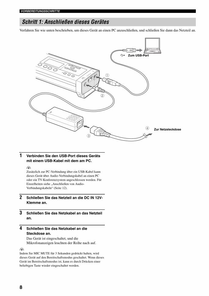
VORBEREITUNGSSCHRITTE
8
Verfahren Sie wie unten beschrieben, um dieses Gerät an einen PC anzuschließen, und schließen Sie dann das Netzteil an.
1 Verbinden Sie den USB-Port dieses Geräts mit einem USB-Kabel mit dem am PC.
yZusätzlich zur PC-Verbindung über ein USB-Kabel kann dieses Gerät über Audio-Verbindungskabel an einen PC oder ein TV-Konferenzsystem angeschlossen werden. Für Einzelheiten siehe „Anschließen von Audio-Verbindungskabeln“ (Seite 12).
2 Schließen Sie das Netzteil an die DC IN 12V-Klemme an.
3 Schließen Sie das Netzkabel an das Netzteil an.
4 Schließen Sie das Netzkabel an die Steckdose an.Das Gerät ist eingeschaltet, und die Mikrofonanzeigen leuchten der Reihe nach auf.
yIndem Sie MIC MUTE für 3 Sekunden gedrückt halten, wird dieses Gerät auf den Bereitschaftsmodus geschaltet. Wenn dieses Gerät im Bereitschaftsmodus ist, kann es durch Drücken einer beliebigen Taste wieder eingeschaltet werden.
Schritt 1: Anschließen dieses Gerätes
3
4
1
2
Zur Netzsteckdose
Zum USB-Port

VORBEREITUNGSSCHRITTE
9
VO
RB
ER
EIT
UN
GD
eutsch
Zur Verwendung dieses Geräts als externe Mikrofon-/Lautsprechereinheit Ihres Konferenzsystems führen Sie folgende Einstellungen am PC aus.Die folgende Beschreibung nimmt einen PC, der mit Windows XP läuft, als Beispiel.
yDieses Gerät wird vom PC als Standard-USB-Audiogerät erkannt. Separate Installation eines Treibers ist deshalb nicht erforderlich.
1 Klicken Sie auf das „Start“-Menü und dann auf „Settings“ - „Control Panel“.
2 Klicken Sie „Sounds, Speech and Audio Devices“.
3 Klicken Sie „Sounds and Audio Devices“.Das Kästchen „Sounds and Audio Devices Properties“ öffnet sich.
4 Klicken Sie auf das Register „Audio“.
5 Ändern Sie die Einstellungen wie folgt.• „Sound Playback“ Feld - „Default device“:
YAMAHA PJP-100UH• „Sound Recording“ Feld: „Default device“:
YAMAHA PJP-100UH
Schritt 2: Ändern der Einstellungen des PCs
Klicken.
Klicken.
Klicken.
Ändern.
Ändern.

VORBEREITUNGSSCHRITTE
10
6 Klicken Sie auf das Register „Voice“.
7 Ändern Sie die Einstellungen wie folgt.• „Voice playback“ Feld - „Default device“:
YAMAHA PJP-100UH• „Voice recording“ Feld - „Default device“:
YAMAHA PJP-100UH
8 Klicken Sie auf „OK“, um das Kästchen „Sounds and Audio Devices Properties“ zu verlassen.
Klicken.
Ändern.
Ändern.
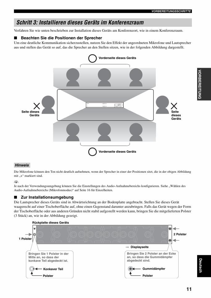
VORBEREITUNGSSCHRITTE
11
VO
RB
ER
EIT
UN
GD
eutsch
Verfahren Sie wie unten beschrieben zur Installation dieses Geräts am Konferenzort, wie in einem Konferenzraum.
■ Beachten Sie die Positionen der SprecherUm eine deutliche Kommunikation sicherzustellen, nutzen Sie den Effekt der angeordneten Mikrofone und Lautsprecher aus und stellen das Gerät so auf, das die Sprecher an den Stellen sitzen, wie in der folgenden Abbildung dargestellt.
Die Mikrofone können den Ton nicht deutlich aufnehmen, wenn der Sprecher in einer der Positionen sitzt, die in der obigen Abbildung mit „x“ markiert sind.
yJe nach der Verwendungsumgebung können Sie die Einstellungen des Audio-Aufnahmebereichs konfigurieren. Siehe „Wählen des Audio-Aufnahmebereichs (Mikrofonmodus)“ auf Seite 16 für Einzelheiten.
■ Zur InstallationsumgebungDie Lautsprecher dieses Geräts sind in Abwärtsrichtung an der Bodenplatte angebracht. Stellen Sie dieses Gerät waagerecht auf einer Tischoberfläche auf, ohne einen Gegenstand darunter anzubringen. Falls das Gerät wegen der Form der Tischoberfläche oder aus anderen Gründen nicht stabil aufgestellt werden kann, bringen Sie die mitgelieferten Polster (3 Stück) an, wie in der Abbildung gezeigt.
Schritt 3: Installieren dieses Geräts im Konferenzraum
Hinweis
Vorderseite dieses Geräts
Vorderseite dieses Geräts
Seite diesesGeräts
Seite dieses Geräts
Displayseite
Rückplatte dieses Geräts
1 Polster
Konkaver Teil
Polster
Gummidämpfer
Polster
Bringen Sie 1 Polster in der Mitte an, so dass der konkave Teil abgedeckt ist.
Bringen Sie 2 Polster an der Ecke an, so dass die Gummidämpfer abgedeckt sind.
2 Polster

VERBINDUNG MIT AUDIO-VERBINDUNGSKABELN
12
Zusätzlich zur PC-Verbindung über ein USB-Kabel kann dieses Gerät über Audio-Verbindungskabel an einen PC oder ein TV-Konferenzsystem angeschlossen werden. Verfahren Sie wie folgt für die Verbindungen und Einstellungen.
Legen Sie zwei handelsübliche Audio-Verbindungskabel bereit (Stereo-Minibuchsen-Kabel).
Bei der folgenden Beschreibung wird angenommen, dass die Eingangs-/Ausgangsbuchsen des PCs zur Erkennung farbig codiert sind. Falls Ihr PC keine farbigen Buchsen hat, schlagen Sie in der Dokumentation des PCs nach, um die Funktionen und Lage der Eingangs-/Ausgangsbuchsen vor dem Anschluss zu bestätigen.
1 Verbinden Sie die AUDIO IN-Buchse an diesem Gerät mit der Audio-Ausgangsbuchse am PC oder Video-Konferenzsystem.Zum Anschließen eines PCs verbinden Sie das Kabel mit der grünen Buchse am PC.
2 Verbinden Sie die AUDIO OUT-Buchse an diesem Gerät mit der Audio-Eingangsbuchse am PC oder Video-Konferenzsystem.Zum Anschließen eines PCs verbinden Sie das Kabel mit der blauen Buchse am PC.
Verbinden Sie nicht das Kabel mit der Mikrofon-Eingangsbuchse (die beim PC rot ist) des PC- oder Video-Konferenzsystems. Andernfalls kann ein zu hoher Eingangssignalpegel die Audioqualität beeinträchtigen.
VERBINDUNG MIT AUDIO-VERBINDUNGSKABELN
Anschließen von Audio-Verbindungskabeln
Hinweis
1
2
(Blaue Buchse am PC)Zur Audio-Eingangsbuchse
Zur Audio-Ausgangsbuchse (Grüne Buchse am PC)
Hinweis

VERBINDUNG MIT AUDIO-VERBINDUNGSKABELN
13
VO
RB
ER
EIT
UN
GD
eutsch
Die PC-Einstellungen müssen so angepasst werden, dass der Audioeingang von diesem Gerät zum PC nicht zu diesem Gerät ausgegeben wird. Da der Ton von diesem Gerät von der Line-Eingangsbuchse am PC eingegeben wird, ist es außerdem erforderlich, die Einstellung so zu ändern, dass der Audioeingang von der Line-Eingangsbuchse akzeptiert wird.
1 Öffnen Sie das Kästchen „Sounds and Audio Devices Properties“, indem Sie die Schritte 1 bis 3 in Seite 9 ausführen.
2 Klicken Sie auf das Register „Audio“.
3 Im „Sound Playback“-Feld klicken Sie „Volume...“.
Das Kästchen „Volume Control“ öffnet sich.
4 Im „Line In“-Feld klicken Sie „Mute“ zur Prüfung.
5 Im „Sound recording“-Feld klicken Sie „Volume...“.
Das Kästchen „Recording Control“ öffnet sich.
6 Im „Line-In“-Feld klicken Sie „Select“ zur Prüfung.
Ändern der Einstellungen des PCs
Klicken.
Klicken.
Markieren.
Klicken.
Markieren.
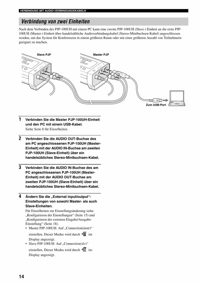
VERBINDUNG MIT AUDIO-VERBINDUNGSKABELN
14
Nach dem Verbinden des PJP-100UH mit einem PC kann eine zweite PJP-100UH (Slave-) Einheit an die erste PJP-100UH (Master-) Einheit über handelsübliche Audioverbindungskabel (Stereo-Minibuchsen-Kabel) angeschlossen werden, um das System für Konferenzen in einem größeren Raum oder mit einer größeren Anzahl von Teilnehmern geeignet zu machen.
1 Verbinden Sie die Master PJP-100UH-Einheit und den PC mit einem USB-Kabel.Siehe Seite 8 für Einzelheiten.
2 Verbinden Sie die AUDIO OUT-Buchse des am PC angeschlossenen PJP-100UH (Master-Einheit) mit der AUDIO IN-Buchse am zweiten PJP-100UH (Slave-Einheit) über ein handelsübliches Stereo-Minibuchsen-Kabel.
3 Verbinden Sie die AUDIO IN-Buchse des am PC angeschlossenen PJP-100UH (Master-Einheit) mit der AUDIO OUT-Buchse am zweiten PJP-100UH (Slave-Einheit) über ein handelsübliches Stereo-Minibuchsen-Kabel.
4 Ändern Sie die „External input/output“-Einstellungen von sowohl Master- als auch Slave-Einheiten.Für Einzelheiten zur Einstellungsänderung siehe „Konfigurieren der Einstellungen“ (Seite 15) und „Konfigurieren der externen Eingabe/Ausgabe-Einstellung“ (Seite 18).• Master PJP-100UH: Auf „Connection(mstr)“
einstellen. Dieser Modus wird durch im
Display angezeigt.• Slave PJP-100UH: Auf „Connection(slv)“
einstellen. Dieser Modus wird durch im
Display angezeigt.
Verbindung von zwei Einheiten
Slave PJP Master PJP
Zum USB-Port

15
KO
NFIG
UR
ATION
EN
Deu
tsch
Sie können die Einstellungen dieser Einheit mit den Bedientasten an dieser Einheit konfigurieren.
Siehe „Einstellmenü-Liste“ (Seite 16) für Einzelheiten zur Einstellmenü-Konfiguration und Parameter jedes Menüpunkts.
1 Drücken Sie in der Anfangsanzeige.
Das „Settings“-Menü erscheint.
2 Drücken Sie oder , um die Menükategorie zu wählen, und drücken Sie danach .Die Menüpunkte in der gewählten Kategorie erscheinen. Die folgende Abbildung ist ein Beispiel, wo „1. Sound Settings“ gewählt ist. Für Einzelheiten zur Einstellmenü-Konfiguration siehe „Einstellmenü-Liste“ (Seite 16).
3 Ändern Sie den Parameter.Die folgende Abbildung ist ein Beispiel, wo „2. Speaker Mode“ gewählt ist. Für Einzelheiten zu Parametern für jeden Menüpunkt siehe „Einstellmenü-Liste“ (Seite 16).
4 Zur Bestätigung der Einstellung drücken Sie .
Die Einstellung wird in diesem Gerät gespeichert.
Zum Zurückkehren zum vorhergehenden Menü ohne Speichern der EinstellungDrücken Sie .
KONFIGURIEREN DER EINSTELLUNGEN
Hinweis
3. Restore Settings2. General Settings1. Sound Settings
Settings
3. Room Size2. Speaker Mode1. Microphone Mode
Sound Settings
3. Medium Area2. Small Area1. Monaural
Speaker Mode

EINSTELLMENÜ-LISTE
16
Dieser Abschnitt beschreibt die Einstellmenüpunkte, die mit diesem Gerät verfügbar sind.
■ Wählen des Audio-Aufnahmebereichs (Mikrofonmodus)
Sie können den Audio-Aufnahmebereich des Mikrofons während des Rufs wählen. Die Vorgabeeinstellung ist „Zone“.• Zone: Den Ton in einem großen Bereich aufnehmen,
und nicht nur den Ton des Sprechers verfolgen. Geeignet für eine relativ ruhige Umgebung. Verwenden Sie die Gebietswahltasten im Menü „Microphone Mode“ zum Festlegen des Aufnahmebereichs, und
drücken Sie dann . Je nach den gedrückten Tasten wird das Audio in dem Bereich in der folgenden Abbildung aufgenommen oder nicht.
Mikrofonanzeigen (blaue LED) der Richtung, in der Audio von allen aufgenommen werden kann, leuchten auf. Dieser Modus wird durch im Display angezeigt.
y• Drücken Sie , um Audio aus allen Richtungen aufzunehmen. • Sie können mehrere Bereiche gleichzeitig wählen. Die Sets der wählberen
Bereiche sind [ + ], [ + ] oder alle Bereiche. • Spot: Sie den Audio-Aufnahmebereich auf die Position
vor dem Mikrofon fest, indem Sie die Richtcharakteristik schmälern. Dieser Modus ist geeignet, wenn nur eine oder zwei Personen sprechen, oder wo geräuscherzeugende Geräte in der Nähe sind, wie ein Projektor. Verwenden Sie die Gebietswahltasten im Menü „Microphone Mode“ zum Festlegen des
Aufnahmebereichs, und drücken Sie dann . Je nach den gedrückten Tasten wird Audio in den Bereichen in der folgenden Abbildung aufgenommen oder nicht.
Mikrofonanzeigen (blaue LED) der Richtung, in der Audio von allen aufgenommen werden kann, leuchten auf. Dieser Modus wird durch im Display angezeigt.
ySie können mehrere Bereiche gleichzeitig wählen. Die Sets der
wählbaren Bereiche sind [ + ], [ + ], [ + ] oder alle Bereiche.• Track: Das Mikrofonsystem verfolgt und fokussiert
automatisch das Audio des Sprechers, ohne den Audio-Aufnahmebereich festzulegen (nur das Audio von einem Sprecher zur Zeit kann aufgenommen werden). Das Audio kann mit enger Richtcharakteristik aufgenommen werden, so dass andere Geräusche verringert werden können. Geeignet, um Ton deutlich in einer Umgebung mit Störgeräuschen aufzunehmen.
EINSTELLMENÜ-LISTE
Konfigurieren der Klang-Einstellungen
Innerhalb von 2 m
Innerhalb von 2 m
Innerhalb von 2 m
Innerhalb von 2 m
Innerhalb von 2 m
Innerhalb von 2 m
Automatische Verfolgung der Richtung des Sprechers
Heute...
Nächste...

17
EINSTELLMENÜ-LISTEK
ON
FIGU
RATIO
NE
ND
eutsch
Zum Festlegen des Bereichs für dieses Merkmal verwenden Sie die Bereichswahltasten im „Microphone Mode“-Menü und drücken Sie dann . Je nach den gedrückten Tasten wird Audio in dem Bereich in der folgenden Abbildung aufgenommen oder nicht.
Mikrofonanzeigen (blaue LED) der Richtung, in der Audio aufgenommen werden kann, leuchten auf. Dieser Modus wird durch im Display angezeigt.
y• Drücken Sie , um Audio aus allen Richtungen
aufzunehmen.• Sie können mehrere Bereiche gleichzeitig wählen.• Sie können Bereiche wählen, wo das Audio-Aufnahmemerkmal
nicht angewendet wird.
Verwendung der Tasten an diesem GerätIm Anfangsdisplay wählen Sie „Settings“ → „Sound Settings“ → „Microphone Mode“.
ySie können das „Microphone Mode“-Menü anzeigen, indem Sie
kontinuierlich im Anfangsdisplay oder Rufdisplay drücken.
■ Konfigurieren des Lautsprecher-ModusSie können den Modus des Audio-Ausgangs von den Lautsprechern beim Ruf wählen. Die Vorgabeeinstellung ist „Divide“.• Monaural (Vorgabe): Auch bei einem Ruf mit mehr
als einem Ort wird das Audio von anderen Einheiten nicht entsprechend ihren Orten aufgeteilt. Dieser
Modus wird durch im Display angezeigt.
• Small Area: Der Bereich, von dem das Audio von anderen Einheiten begrenzt ist wie unten gezeigt (monophoner Ausgang). Dieser Modus wird durch
im Display angezeigt.
• Medium Area: Der Bereich, von dem das Audio von anderen Einheiten begrenzt ist wie unten gezeigt (monophoner Ausgang). Dieser Modus wird durch
im Display angezeigt.
• Large Area: Der Bereich, von dem das Audio von anderen Einheiten begrenzt ist wie unten gezeigt (monophoner Ausgang). Dieser Modus wird durch
im Display angezeigt.
Verwendung der Tasten an diesem GerätIm Anfangsdisplay wählen Sie „Settings“ → „Sound Settings“ → „Speaker Mode“.
y
Sie können das „Speaker Mode“-Menü anzeigen, indem Sie
kontinuierlich im Anfangsdisplay oder Rufdisplay drücken.
■ Konfigurieren der RaumgrößeSie können diese Einstellung je nach Raumgröße und Betriebsumgebung konfigurieren. Sie brauchen sie allerdings normalerweise nicht von „Large“ (Vorgabeeinstellung) zu ändern.• Large (Vorgabe): Position zur Verwendung der Einheit
in einem gewöhnlichen Konferenzraum, offenen Bereich oder Büro. Die Kommunikationsqualität ist in dieser Einstellung am stabilsten. Diese Einstellung
wird durch im Display angezeigt.• Medium: Wählen Sie diese Position, wenn Echo von
der Gegenseite der Kommunikation bei der Vorgabeposition „Large“ hörbar wird. Diese Position wird gewählt, wenn die Einheit in einem Raum mit starkem Nachhall verwendet wird. Diese Einstellung
wird durch im Display angezeigt.• Small: Wählen Sie diese Position, wenn Echo
weiterhin von der Gegenseite der Komunikation bei der Position „Medium“ hörbar wird. Diese Einstellung
wird durch im Display angezeigt.
Innerhalb von 2 m
Innerhalb von 2 m
18
EINSTELLMENÜ-LISTE
• Raumgröße ist die Funktion zur Verringerung von Echo bei der Gegenseite der Kommunikation. Raumgröße kann nicht das Echo verringern, das von der am lokalen Ort installierten Einheit gehört wird.
• Die Positionen „Medium“ und „Small“ können die Echo-Verarbeitungskapazität steigern, senken aber die Kommunikationsqualität. Diese Positionen sollten nur gewählt werden, wenn Echo von der Gegenseite gehört wird.
Verwendung der Tasten an diesem GerätIm Anfangsdisplay oder im Display bei der Kommunikation wählen Sie „Settings“ → „Sound Settings“ → „Room Size“.
■ Konfigurieren der externen Eingabe/Ausgabe-Einstellung
Sie müssen diese Einstellung konfigurieren, wenn Sie ein externes Audiogerät an diese Einheit anschließen. Die Vorgabeeinstellung ist „None“.• None: Deaktiviert die externe Eingabe/Ausgabe.• Audio (Vorgabe): Wählen Sie diese Einstellung beim
Anschließen externer Audiogeräte an diese Einheit.• Gekoppelt: Wenn gekoppelte Verbindung zweier
Einheiten (Seite 14) verwendet wird, wählen Sie diese Einstellung am an den PC angeschlossenen PJP über USB (Master-Einheit).
Verwendung der Tasten an diesem GerätIm Anfangsdisplay wählen Sie „Settings“ → „Sound Settings“ → „External I/O“.
■ Anpassen des LCD-KontrastsSie können den Displaykontrast anpassen, indem Sie VOL +/– drücken.
Verwendung der Tasten an diesem GerätIm Anfangsdisplay wählen Sie „Settings“ → „General Settings“ → „LCD Contrast“.
■ Rücksetzen auf werkseitige Einstellungen dieses Geräts
Sie können die werkseitigen Einstellungen dieses Geräts wieder herstellen. Siehe „Rücksetzen des Geräts“ auf Seite 23 für Einzelheiten.
Durch Rücksetzen auf werkseitige Einstellungen werden alle vorgenommenen Einstellungen gelöscht.
Verwendung der Tasten an diesem GerätIm Anfangsdisplay wählen Sie „Settings“ → „Restore Settings“.
Hinweise Konfigurieren der generellen Einstellung
Rücksetzen auf werkseitige Einstellungen
Hinweis

19
KO
NFIG
UR
ATION
EN
Deu
tsch
Sie können die Firmware (Programm zur Steuerung der Funktionen dieses Geräts) zur Verwendung der neuesten Merkmale herunterladen.
Zur Verwendung der Revision-Aktualisierungsfunktion müssen Sie die folgende Software-Lizenzvereinbarung akzeptieren.
1 Genehmigung zur VerwendungDiese Software-Lizenzvereinbarung soll der Yamaha Corporation (im Folgenden als „Yamaha“) bezeichnet erlauben, Ihnen die Verwendung der Firmware (im Folgenden „dieses Programm“ genannt) für den YamahaKonferenzmikrofon-Lautsprecher (im Folgenden „dieses Produkt“ genannt) zu gestatten. Sie können dieses Programm downloaden, nachdem Sie die Bedingungen und Konditionen der vorliegenden Software-Lizenzvereinbarung akzeptiert haben.Die vorliegende Software-Lizenzvereinbarung gilt für die heruntergeladene Kopie dieses Programms ebenso wie jegliche Kopien, die im Rahmen der vorliegenden Software-Lizenzvereinbarung erstellt werden.
2 Einschränkung der WeitergabeSie dürfen dieses Programm nur zum Zweck der Aktualisierung der Funktionen dieses Produkts downloaden. Es ist nicht zulässig, dieses Programm auf einer Webseite zur Verfügung zu stellen, die der breiten Öffentlichkeit zugänglich ist, ausgenommen wenn dazu eine direkte Genehmigung von Yamaha vorliegt.
3 Erstellen von DuplikatenSie dürfen nicht Duplikate dieses Programms erstellen, ausgenommen wo zu Sicherungszwecken erforderlich, oder zur Aktualisierung von mehr als einer Ausgabe dieses Produkts.
4 Einschränkungen für Dekompilieren, Reverse-Engineering oder Zerlegen
Sie dürfen dieses Programm unter keinen Umständen dekompilieren, Reverse-Engineering unterziehen, zerlegen, modifizieren, anderen zugänglich machen, vertreiben, oder derivative Versionen dieses Programms irgendwelcher Art herstellen.
5 Begrenzung der HaftpflichtUnter allen Umständen, einschließlich eigene Nachlässigkeit, übernimmt Yamaha keine Haftung jeglicher Art für mögliche Verluste, die dem Kunden durch die vorliegende Software-Lizenzvereinbarung entstehen.
6 ExportkontrolleSie müssen alle bestehenden Gesetze und Bestimmungen aller relevanten Länder, einschließlich aber nicht beschränkt auf Japan und Ihr Land, befolgen. Sie dürfen nicht, weder direkt noch indirekt, dieses Programm exportieren oder re-exportieren, ausgenommen unter Befolgung aller zutreffender Gesetze und Bestimmungen.
7 Begrenztes Angebot für Einwohner JapansDiese Software-Lizenzvereinbarung unterliegt den Gesetzen und Vorschriften Japans und Ihres Landes, und die Auslegung dieser Vereinbarung erfolgt gemäß den Gesetzen von Japan.
AKTUALISIEREN DER FIRMWARE
Software-Lizenzvereinbarung
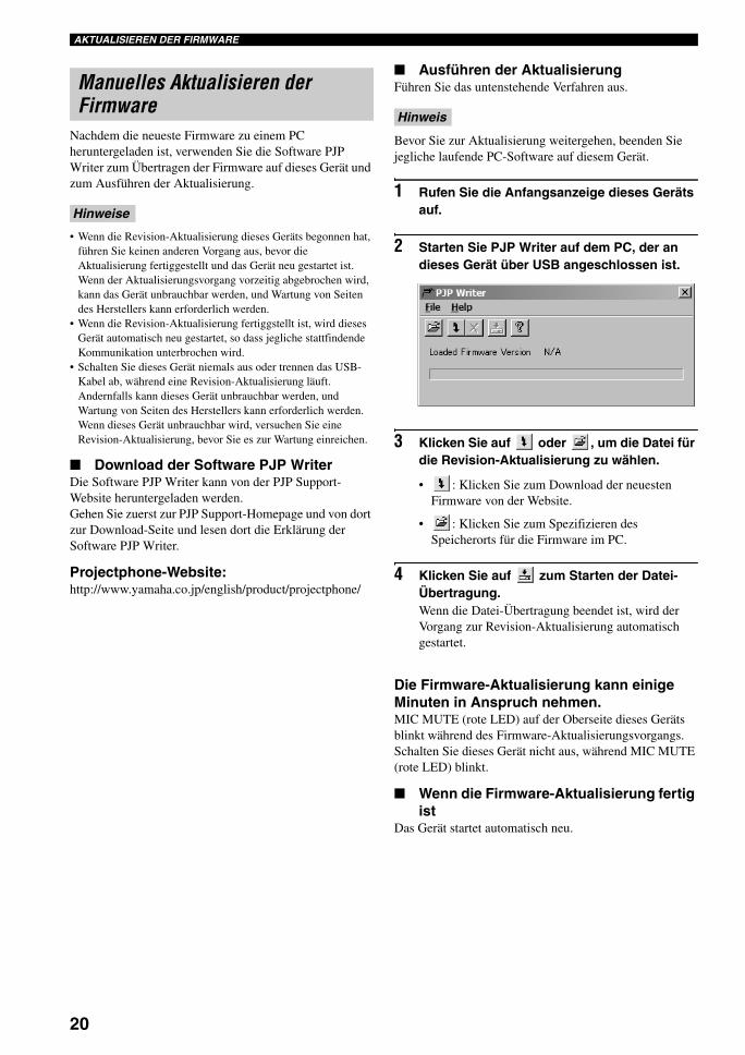
20
AKTUALISIEREN DER FIRMWARE
Nachdem die neueste Firmware zu einem PC heruntergeladen ist, verwenden Sie die Software PJP Writer zum Übertragen der Firmware auf dieses Gerät und zum Ausführen der Aktualisierung.
• Wenn die Revision-Aktualisierung dieses Geräts begonnen hat, führen Sie keinen anderen Vorgang aus, bevor die Aktualisierung fertiggestellt und das Gerät neu gestartet ist. Wenn der Aktualisierungsvorgang vorzeitig abgebrochen wird, kann das Gerät unbrauchbar werden, und Wartung von Seiten des Herstellers kann erforderlich werden.
• Wenn die Revision-Aktualisierung fertiggstellt ist, wird dieses Gerät automatisch neu gestartet, so dass jegliche stattfindende Kommunikation unterbrochen wird.
• Schalten Sie dieses Gerät niemals aus oder trennen das USB-Kabel ab, während eine Revision-Aktualisierung läuft. Andernfalls kann dieses Gerät unbrauchbar werden, und Wartung von Seiten des Herstellers kann erforderlich werden. Wenn dieses Gerät unbrauchbar wird, versuchen Sie eine Revision-Aktualisierung, bevor Sie es zur Wartung einreichen.
■ Download der Software PJP WriterDie Software PJP Writer kann von der PJP Support-Website heruntergeladen werden.Gehen Sie zuerst zur PJP Support-Homepage und von dort zur Download-Seite und lesen dort die Erklärung der Software PJP Writer.
Projectphone-Website:http://www.yamaha.co.jp/english/product/projectphone/
■ Ausführen der AktualisierungFühren Sie das untenstehende Verfahren aus.
Bevor Sie zur Aktualisierung weitergehen, beenden Sie jegliche laufende PC-Software auf diesem Gerät.
1 Rufen Sie die Anfangsanzeige dieses Geräts auf.
2 Starten Sie PJP Writer auf dem PC, der an dieses Gerät über USB angeschlossen ist.
3 Klicken Sie auf oder , um die Datei für die Revision-Aktualisierung zu wählen.
• : Klicken Sie zum Download der neuesten Firmware von der Website.
• : Klicken Sie zum Spezifizieren des Speicherorts für die Firmware im PC.
4 Klicken Sie auf zum Starten der Datei-Übertragung.Wenn die Datei-Übertragung beendet ist, wird der Vorgang zur Revision-Aktualisierung automatisch gestartet.
Die Firmware-Aktualisierung kann einige Minuten in Anspruch nehmen.MIC MUTE (rote LED) auf der Oberseite dieses Geräts blinkt während des Firmware-Aktualisierungsvorgangs. Schalten Sie dieses Gerät nicht aus, während MIC MUTE (rote LED) blinkt.
■ Wenn die Firmware-Aktualisierung fertig ist
Das Gerät startet automatisch neu.
Manuelles Aktualisieren der Firmware
Hinweise
Hinweis
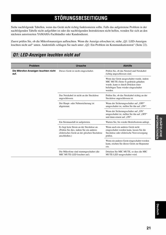
21
ZUS
ÄT
ZLIC
HE
IN
FO
RM
AT
ION
EN
Deu
tsch
Siehe nachfolgende Tabellen, wenn das Gerät nicht richtig funktionieren sollte. Falls das aufgetretene Problem in der nachfolgenden Tabelle nicht aufgeführt ist oder die nachfolgenden Instruktionen nicht helfen, wenden Sie sich an den nächsten autorisierten YAMAHA-Fachhändler oder Kundendienst.
Zuerst prüfen Sie, ob die Mikrofonanzeigen aufleuchten. Wenn die Anzeige erloschen ist, siehe „Q1: LED-Anzeigen leuchten nicht auf“ unten. Andernfalls schlagen Sie nach unter „Q2: Ein Problem im Kommunikationston“ (Seite 22).
STÖRUNGSBESEITIGUNG
Q1: LED-Anzeigen leuchten nicht auf
Problem Ursache Abhilfe
Die Mikrofon-Anzeigen leuchten nicht auf.
Dieses Gerät ist nicht eingeschaltet. Prüfen Sie, ob das Netzteil und Netzkabel richtig angeschlossen sind.
Wenn das Gerät ausgeschaltet wurde, indem MIC MUTE (Seite 4) gedrückt gehalten wurde, kann es durch Drücken einer beliebigen Taste wieder eingeschaltet werden.
Das Netzkabel ist nicht an der Steckdose angeschlossen.
Prüfen Sie, ob das Netzkabel richtig an der Steckdose angeschlossen ist.
Der Haupt- oder Nebensicherung ist abgetrennt.
Wenn der Sicherungsschalter auf „OFF“ umgeschaltet ist, stellen Sie ihn auf „ON“.
Wenn der Sicherungsschalter auf „ON“ umgeschaltet ist, stellen Sie ihn auf „OFF“ und dann erneut auf „ON“.
Ein Stromausfall ist aufgetreten. Warten Sie, bis wieder Betriebsstrom anliegt.
Es liegt kein Strom an der Steckdose an. (Prüfen Sie dies, indem Sie ein anderes elektrisches Gerät an der gleichen Steckdose anschließen.)
Wenn auch ein anderes Gerät nicht eingeschaltet werden kann, lassen Sie die Steckdose oder elektrische Netzversorgung prüfen.
Wenn ein anderes Gerät eingeschaltet werden kann, reichen Sie dieses Gerät zur Reparatur ein.
Die Mikrofone sind stummgeschaltet (die MIC MUTE-LED leuchtet auf).
Drücken Sie MIC MUTE, so dass die MIC MUTE-LED ausgeschaltet wird.

22
STÖRUNGSBESEITIGUNG
Q2: Ein Problem im Kommunikationston
Problem Ursache Abhilfe
Das Audio vom anderen Gerät kann nicht gehört werden.
Die Mikrofone am anderen Gerät sind stummgeschaltet.
Heben Sie die Stummschaltung am anderen Gerät auf.
Das Audio wird unterbrochen. Audio-Verbindungskabel sind abgetrennt oder falsch angeschlossen.
Schließen Sie die Audio-Verbindungskabel sicher an.
Das USB-Kabel ist abgetrennt oder falsch angeschlossen.
Schließen Sie das USB-Kabel sicher an.
Das USB-Kabel ist nicht richtig angeschlossen.
Prüfen Sie, ob das USB-Kabel fest angeschlossen ist.
Das Gerät erzeugt Rückkopplungsgeräusche.
Das Gerät ist an einer Wand aufgestellt. Stellen Sie das Gerät in einem ausreichenden Abstand zur Wand auf.
Ein Gegenstand befindet sich neben diesem Gerät.
Vermeiden Sie es, Gegenstände vor den Mikrofonen aufzustellen.
Dieses Gerät wird in einem Raum mit starkem Nachhall verwendet.
Stellen Sie Gegenstände mit hoher Schallabsorption in den Raum, aber nicht direkt vor die Mikrofone.
Vermeiden Sie es, sehr laut zu sprechen, um Nachhall zu vermeiden.
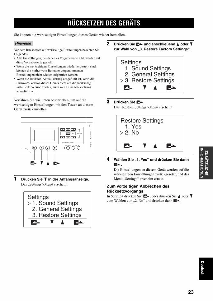
23
ZUS
ÄT
ZLIC
HE
IN
FO
RM
AT
ION
EN
Deu
tsch
Sie können die werkseitigen Einstellungen dieses Geräts wieder herstellen.
Vor dem Rücksetzen auf werkseitige Einstellungen beachten Sie Folgendes.• Alle Einstellungen, bei denen es Vorgabewerte gibt, werden auf
diese Vorgabewerte gestellt.• Wenn die werkseitigen Einstellungen wiederhergestellt sind,
können die vorher vom Benutzer vorgenommenen Einstellungen nicht wieder aufgerufen werden.
• Wenn die Revision-Aktualisierung ausgeführt ist, kehrt die Firmware-Version dieses Geräts nicht auf die werkseitig installierte Version zurück, auch wenn eine Rücksetzung ausgeführt wird.
Verfahren Sie wie unten beschrieben, um auf die werkseitigen Einstellungen mit den Tasten an diesem Gerät zurückzustellen.
1 Drücken Sie in der Anfangsanzeige.Das „Settings“-Menü erscheint.
2 Drücken Sie und anschließend oder zur Wahl von „3. Restore Factory Settings“.
3 Drücken Sie .Das „Restore Settings“-Menü erscheint.
4 Wählen Sie „1. Yes“ und drücken Sie dann .
Die Einstellungen an diesem Gerät werden auf die werkseitigen Einstellungen zurückgesetzt, und das Menü „Settings“ erscheint erneut.
Zum vorzeitigen Abbrechen des RücksetzvorgangsIn Schritt 4 drücken Sie , oder drücken Sie oder zum Wählen von „2. No“ und drücken dann .
RÜCKSETZEN DES GERÄTS
Hinweise
MIC MUTE VOL
DC
IN
12
VIN
A
UD
IO O
UT
MIC/SP AREA SELECT
MIC/SPALL
3. Restore Settings2. General Settings1. Sound Settings
Settings
3. Restore Settings2. General Settings1. Sound Settings
Settings
2. No1. Yes
Restore Settings

TECHNISCHE DATEN
24
Allgemeines• Abmessungen (B x H x T) ................... 750 mm x 100 mm x 65 mm• Gewicht (ohne Netzteil) ......................................................... 2,9 kg• Netzspannung/-frequenz
................................. 100 bis 240 V Wechselspannung (50/60 Hz)• Leistungsaufnahme ..............................................................ca. 36 W
Betriebsumgebung• Umgebungstemperatur ......................................................0 bis 40°C• Umgebungsluftfeuchtigkeit ....... 20% bis 85% (keine Kondensation)
Funkstörstandard............................................................................ FCC Teil 15 (US)
EN55022 (EU)
USB-SchnittstellenUSB 2.0 Full Speed• Konform mit USB Audio Class und HID ClassUSB Audio-Format• Kanäle für Aufnahme/Reproduktion• PCM-Abtastfrequenz ............................................................. 16 kHz• Quantisierung ........................................................................... 16-BitWenn eine dedizierte Anwendung verwendet wird• PCM-Abtastfrequenz ............................................................. 16 kHz• Quantisierung ........................................................................... 16-Bit• 3-Kanal-Ausgänge (Audioseparation nach Ort)
Audio-Eingang/Ausgang-Schnittstellen.......................................... Stereo-Analog-Eingang/Ausgang (je 1)
• Anschlüsse................................................................... Mini-Buchsen
Seriell-Schnittstelle.......................................................................................... RS-232C
• Anschlüsse.......................................................................... Mini-DIN
Audio• Angeordnete Mikrofone (geregelte Richtwirkung)• Zonen-Audioaufnahme-Funktion• Spot-Audioaufnahme-Funktion• Mikrofon-Autotracking-Funktion
Signalverarbeitung• 3-kanalige adaptive Echounterdrückung• Mikrofon/Lautsprecher-Anordnungsregelung
Zubehör• Netzteil (PJP-PS01) x 1• Netzkabel x 1• USB-Kabel x 1• Benutzerhandbuch (diese Anleitung) x 1• Garantiekarte x 1
* Die technischen Daten können jederzeit ohne vorherige Vorankündigung geändert werden.
TECHNISCHE DATEN

25
ZUS
ÄT
ZLIC
HE
IN
FO
RM
AT
ION
EN
Deu
tsch
Vor der Weigergabe dieses Geräts müssen Sie die Einstellungen auf werkseitige Vorgaben zurücksetzen.
Bei der Weitergabe dieses Gerät immer zusammen mit dem Benutzerhandbuch (dieser Anleitung) übergaben.
Wenn dieses Gerät ohne Rücksetzung auf die werkseitigen Vorgaben weitergereicht wird, können im Gerät gespeicherte Informationen von Dritten missbraucht werden.Anweisungen zum Rücksetzen auf werkseitige Vorgabeeinstellungen siehe „Rücksetzen des Geräts“ (Seite 23).
HINWEISE ZUR WEITERGABE/ENTSORGE DIESES GERÄTS
Hinweis


YAMAHA CORPORATION 10-1 Nakazawa-cho, Hamamatsu, Shizuoka 430-8650, Japan
© 2006 All rights reserved.
Printed in Japan WJ19480
This owner’s manual is based on the firmware version 1.1x. The functions and specifications could be possibly added or changed by a firmware update.Visit the PJP website to obtain the latest firmware and manuals.
PJP website:http://www.yamaha.co.jp/english/product/projectphone/
Ce mode d’emploi se réfère à la version 1.1x du micrologiciel. Desfonctions et spécifications peuvent être ajoutées ou changées par unemise à jour du micrologiciel.Consultez le site PJP pour obtenir les tout derniers micrologiciel etmanuels.
Site PJP:http://www.yamaha.co.jp/english/product/projectphone/
Dieses Benutzerhandbuch basiert auf der Firmware-Version 1.1x. DieFunktionen und technischen Daten können möglicherweise durch einezukünftige Firmware-Aktualisierung erweitert oder geändert werden.Besuchen Sie die PJP-Website zum Erhalten der neuesten Firmwareund Anleitungen.
PJP-Website:http://www.yamaha.co.jp/english/product/projectphone/
As of September, 2006
01EN_PJP-100UH_UCGB_cv-4.fm Page 26 Friday, August 25, 2006 10:56 AM