configuration guide - audiocodes · pdf fileconfiguration guide . ... it provides a...
TRANSCRIPT

Configuration Guide Configuring MSBR for LAN & WAN Access
using CLI
Version 6.8
Multi-Service Business Routers (MSBR) Access, Data, Voice & Security
Session Border Controller (SBC)

Configuration Guide Contents
Version 6.8 3 Mediant MSBR
Table of Contents 1 Introduction ......................................................................................................... 7
2 Cellular Interfaces (3G vs. 4G) ........................................................................... 9
2.1 Examples ............................................................................................................. 10
3 PPP and PPPoE ................................................................................................. 13
3.1 Examples ............................................................................................................. 14
4 ADSL/VDSL ........................................................................................................ 15
4.1 ADSL Examples ................................................................................................... 16 4.2 Examples ............................................................................................................. 17
5 ATM-based Interfaces and Encapsulation ...................................................... 19
5.1 Examples ............................................................................................................. 20
6 EFM Interfaces ................................................................................................... 23
6.1 Examples ............................................................................................................. 23
7 SHDSL - EFM/ATM ............................................................................................. 25
7.1 Examples ............................................................................................................. 26
8 Ethernet OAM .................................................................................................... 29
8.1 What is Ethernet OAM .......................................................................................... 29 8.2 Ethernet CFM (CFM OAM) ................................................................................... 29
8.2.1 Description ...............................................................................................................29 8.2.1.1 Acronyms & Terms ...................................................................................29 8.2.1.2 CFM Sub-Protocols ..................................................................................30
8.2.2 CFM MPID Configuration.........................................................................................30
9 Ethernet CFM Verification ................................................................................ 33
9.1.1 Show Data Ethernet CFM ........................................................................................33 9.1.2 Ping Ethernet ...........................................................................................................34 9.1.3 Traceroute Ethernet .................................................................................................34 9.1.4 Show Remote Ethernet CFM Maintenance-points ..................................................34
10 Y.1731: OAM Functions and Mechanisms for Ethernet based Networks ..... 37
10.1 Description ........................................................................................................... 37 10.2 Functions for Fault Management .......................................................................... 37
10.2.1 Alarm Indication Signal (AIS) Condition ..................................................................37 10.2.1.1 Ethernet Locked - Signal ETH-LCK .........................................................37
10.3 Functions for Performance Management (Y.1731) ............................................... 38 10.3.1 Set Frame Delay Measurement (ETH-DM) .............................................................38
10.3.1.1 1DM - One-way ETH-DM (using 1DM PDU) ............................................39 10.3.1.2 DMM/DMR - Two-way ETH-DM (using DMM and DMR PDUs) ..............39 10.3.1.3 DMM Reception and DMR Transmission .................................................39
10.4 EFM OAM ............................................................................................................ 42 10.4.1 Description ...............................................................................................................42 10.4.2 Features ...................................................................................................................42
10.4.2.1 Discovery ..................................................................................................42 10.4.2.2 Link Monitoring .........................................................................................42 10.4.2.3 Remote Failure Indication ........................................................................43 10.4.2.4 Remote Loopback ....................................................................................43

Access 4 Document #: LTRT-31666
LAN & WAN Access Interfaces
10.4.2.5 OAM Messages ........................................................................................43 10.4.3 Configuration ...........................................................................................................44 10.4.4 Show Commands ....................................................................................................45
11 Multiple DSL Connection .................................................................................. 49
11.1 Examples ............................................................................................................. 49
12 E1/T1 (PRI) ......................................................................................................... 51
12.1 Examples ............................................................................................................. 52
13 Serial HDLC ....................................................................................................... 53
13.1 Examples ............................................................................................................. 53
14 Fiber Optic ......................................................................................................... 55
14.1 Examples ............................................................................................................. 55
15 WAN Failover ..................................................................................................... 57
15.1 Examples ............................................................................................................. 58 15.1.1 Cold Backup WAN Failover .....................................................................................58 15.1.2 Hot Backup WAN Failover .......................................................................................59
16 Wi-Fi ................................................................................................................... 61
16.1 Examples ............................................................................................................. 64 16.2 Advanced Wi-Fi Example ..................................................................................... 66
17 LLDP ................................................................................................................... 69
17.1 Examples ............................................................................................................. 69

Version 6.8 5 Mediant MSBR
Configuration Guide Notices
Notice Information contained in this document is believed to be accurate and reliable at the time of printing. However, due to ongoing product improvements and revisions, AudioCodes cannot guarantee accuracy of printed material after the Date Published nor can it accept responsibility for errors or omissions. Before consulting this document, check the corresponding Release Notes regarding feature preconditions and/or specific support in this release. In cases where there are discrepancies between this document and the Release Notes, the information in the Release Notes supersedes that in this document. Updates to this document and other documents as well as software files can be downloaded by registered customers at http://www.audiocodes.com/downloads.
© Copyright 2017 AudioCodes Ltd. All rights reserved.
This document is subject to change without notice.
Date Published: July-06-2017
WEEE EU Directive Pursuant to the WEEE EU Directive, electronic and electrical waste must not be disposed of with unsorted waste. Please contact your local recycling authority for disposal of this product.
Customer Support Customer technical support and services are provided by AudioCodes or by an authorized AudioCodes Service Partner. For more information on how to buy technical support for AudioCodes products and for contact information, please visit our Web site at www.audiocodes.com/support.
Abbreviations and Terminology Each abbreviation, unless widely used, is spelled out in full when first used.
Access 6 Document #: LTRT-31666
LAN & WAN Access Interfaces
Document Revision Record
LTRT Description
31660 Initial document release for Version 6.8.
31661 New chapter added for A/VDSL recovery.
31664 New chapters added for Ethernet OAM, Ethernet CFM Verification, Y.1731 and EFM OAM. Removed support for interface termination CO mode.
31666 Updated section for ADSL/VDSL.
Documentation Feedback AudioCodes continually strives to produce high quality documentation. If you have any comments (suggestions or errors) regarding this document, please fill out the Documentation Feedback form on our Web site at http://www.audiocodes.com/downloads.

Configuration Guide 1. Introduction
Version 6.8 7 Mediant MSBR
1 Introduction This document describes the different types of LAN and WAN access interfaces and protocols supported by the MSBR. It provides a description of the commands necessary to configure the type of access as well as typical configuration examples.

Access 8 Document #: LTRT-31666
LAN & WAN Access Interfaces
This page is intentionally left blank.

Configuration Guide 2. Cellular Interfaces (3G vs. 4G)
Version 6.8 9 Mediant MSBR
2 Cellular Interfaces (3G vs. 4G) 3G is the third generation of mobile telecommunications technology. This is based on a set of standards used for mobile devices and mobile telecommunication services. 3G telecommunication networks support services that provide an information transfer rate of at least 200 Kbit/s. The 3G versions 3.5G and 3.75G also provide mobile broadband access of several Mbit/s to smartphones and mobile modems in laptop computers. 4G is the fourth generation of mobile telecommunications technology succeeding 3G. A 4G system, in addition to usual voice and other services of 3G system, provides mobile ultra-broadband Internet access, for example to laptops with USB wireless modems, to smartphones, and to other mobile devices. Two 4G candidate systems are commercially deployed: the Mobile WiMAX standard and the first-release Long Term Evolution (LTE) standard. 4G technologies enable IP-based voice, data and streaming multimedia at higher speeds and offer at least 100 Mbit/s with high mobility and up to 1 GBit/s with low mobility.
Command Description
# configure data Enter data configuration menu.
(config-data)# interface Cellular slot/port
Enter the cellular interface configuration commands. Type interface cellular ? to display slot/port location on MSBR.
(conf-cellular)# pin [pin number] Personal identification number. This is a numeric password shared between a user and a system for authentication. The command pin grants access only when the number is correct.
(conf-cellular)# ppp [user] pass/obscured-pass [password]
Cellular interface can be configured to use PPP authentication protocol when required.
(conf-cellular)# apn [AccessPoint_Name]
Configures the name of the Gateway between 3G/4G mobile network and another computer network (internet). A mobile device making a data connection must be configured with an APN to present to the carrier. The carrier then examines this identifier to determine what type of network connection should be created, for example: what IP addresses should be assigned to the wireless device, what security methods should be used, and how or if, it should be connected to some private customer network.
(conf-cellular)# initstr [AT-Style]
The command set consists of a series of short text strings which combine together to produce complete commands for operations such as dialing, hanging up, and changing the parameters of the connection.

Access 10 Document #: LTRT-31666
LAN & WAN Access Interfaces
2.1 Examples When you attach the cellular modem to MSBR, the MSBR immediately installs drivers.
Figure 2-1: Cellular Interface Example
Looking for target devices ... No devices in target mode or class found Looking for default devices ... Found devices in default mode or class (1) Accessing device 005 on bus 001 ...[4361336.011000] usb 1-1.2: usbfs: process 7445 (usb_modeswitch) did not claim interface 0 before use Getting the current device configuration ... OK, got current device configuration (1) Using endpoints 0x01 (out) and 0x81 (in) Using endpoints 0x01 (out) and 0x81 (in) Inquiring device details; driver will be detached ... Looking for active driver ... OK, driver found ("usb-storage") OK, driver "usb-storage" detached SCSI inquiry data (for identification) ------------------------- Vendor String: HUAWEI Model String: Mass Storage Revision String: 2.31 ------------------------- USB description data (for identification) ------------------------- Manufacturer: Huawei Technologies Product: HUAWEI Mobile Serial No.: not provided ------------------------- Setting up communication with interface 0 ... Using endpoint 0x01 for message sending ... Trying to send message 1 to endpoint 0x01 ... OK, message successfully sent Resetting response endpoint 0x81 Resetting message endpoint 0x01 Checking for mode switch (max. 20 times, once per second) ...
USB 3GCellular Modem
MSBR

Configuration Guide 2. Cellular Interfaces (3G vs. 4G)
Version 6.8 11 Mediant MSBR
Waiting for original device to vanish ... Original device can't be accessed anymore. Good. Searching for target devices ... Searching for target devices ... Searching for target devices ... Searching for target devices ... Searching for target devices ... Found target device, now opening Found correct target device Mode switch succeeded. Bye. After MSBR successfully installs the driver, it configures the cellular interface (but not completely): #configure data (config-data)# interface Cellular 0/0
Configured automatically: (conf-cellular)# ip dns server auto (conf-cellular)# initstr AT&F (means Restore factory settings) (conf-cellular)# apn uinternet (conf-cellular)# phone *99# (conf-cellular)# firewall enable (conf-cellular)# napt (conf-cellular)# mtu auto (conf-cellular)# ip address auto
Configured manually: (conf-cellular)# ppp user orange pass PASSWORD (conf-cellular)# no shutdown (conf-cellular)# pin 1111 (without this command there will be no connection to the internet) (conf-cellular)# exit # Add Default route to traffic through Cellular interface: (config-data)# ip route 0.0.0.0 0.0.0.0 Cellular 0/0
The following show command displays the current status of the interface: # show data interfaces cellular 0/0 Cellular 0/0 is Connected. Description: 3G Cellular PPP connection IP address negotiated using PPP is 10.170.120.150 State Time: 0:01:19 Time since creation: 0:02:25 Time since last counters clear : 0:01:19 mtu auto napt network wan DNS is configured dynamic DNS primary IP address is 82.102.139.10 DNS secondary IP address is 82.102.139.20
Access 12 Document #: LTRT-31666
LAN & WAN Access Interfaces
IPv6 is disabled rx_packets 13 rx_bytes 594 rx_dropped 0 rx_errors 0 tx_packets 13 tx_bytes 416 tx_dropped 0 tx_errors 0 15-seconds input rate: 22 bits/sec, 0 packets/sec 15-seconds output rate: 16 bits/sec, 0 packets/sec Tunnel destination server is (none) Remote server IP: 10.64.64.64 ppp configuration: username: orange, password: (not shown) enabled authentication methods: chap ms-chap ms-chap-v2 pap lcp echo parameters: interval 6, fails
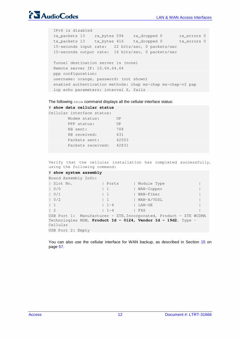
The following show command displays all the cellular interface status: # show data cellular status Cellular interface status: Modem status: UP PPP status: UP KB sent: 708 KB received: 631 Packets sent: 42503 Packets received: 42831
Verify that the cellular installation has completed successfully, using the following command: # show system assembly Board Assembly Info: | Slot No. | Ports | Module Type | | 0/0 | 1 | WAN-Copper | | 0/1 | 1 | WAN-Fiber | | 0/2 | 1 | WAN-A/VDSL | | 1 | 1-4 | LAN-GE | | 2 | 1-4 | FXS | USB Port 1: Manufacturer - ZTE,Incorporated, Product - ZTE WCDMA Technologies MSM, Product Id - 0124, Vendor Id - 19d2, Type - Cellular USB Port 2: Empty
You can also use the cellular interface for WAN backup, as described in Section 15 on page 57.

Configuration Guide 3. PPP and PPPoE
Version 6.8 13 Mediant MSBR
3 PPP and PPPoE Point-to-Point Protocol (PPP) and Point-to-Point Protocol over Ethernet (PPPoE) are network protocols that allow data communication between two network hosts or points. PPPoE is encapsulated in Ethernet frames. Both protocols exist at the network access layer (also known as the data link layer). PPP can be encapsulated in a number of data link layer protocols such as Ethernet (PPPoE). PPP supports three types of user authentication protocols that provide varying levels of security (CHAP/PAP/EAP). PPPoE expands the original capability of PPP by allowing a virtual point-to-point connection over a multipoint Ethernet network architecture, PPPoE is configured as a point-to-point connection between two Ethernet ports. As a tunneling protocol, PPPoE is used as an effective foundation for the transport of IP packets at the network layer.
Command Description
# configure data Enter data configuration menu.
(config-data)# interface pppoe [0-7 interface number]
Enter the PPPoE interface commands.
(conf-pppoe-[number])# underlying [interface slot/port]
Configures the interface with which the PPPoE interface commands are associated.
(conf-pppoe-[number])# ppp user[user name] obscured-pass [pass]
Configures the user and password authentication by using PPP on that interface.
(conf-pppoe-[number])# ppp authentication [chap/pap/ms-chap/ms-chap-v2]
Enables PPP authentication. No limit is placed on which and how many authentication is used (all four can be activated on the same interface). pap: Password Authentication Protocol –
normal login when a connection has been made the host sends a username and password.
chap: Challenge Handshake Authentication Protocol – CHAP does not have these deficiencies. With CHAP, the authenticator (i.e. the server) sends a randomly generated ``challenge'' string to the client, along with its hostname. The client uses the hostname to look up the appropriate secret, combines it with the challenge, and encrypts the string using a one-way hashing function. The result is returned to the server along with the client's hostname.
ms-chap: Microsoft version of CHAP authentication.
(conf-pppoe-[number])# ppp lcp-echo [interval_sec_number] [fails number]
PPP Link Control Protocol (LCP) negotiates the link and PPP parameters to dynamically configure the data link layer of a PPP connection. Interval option: determines how often Echo-
Request messages are sent on idle links to check the viability and integrity of the link.
Fails option: determines how many echo-reply missed before announcing that the link has been broken.

Access 14 Document #: LTRT-31666
LAN & WAN Access Interfaces
3.1 Examples This example shows how to use PPP authentication after plugging in the cellular modem device. You need to enter a username and encrypted password to make the cellular modem authenticate with the server.
Figure 3-1: PPP and PPPoE Example
# configure data MSBR(config-data)# int cellular 0/0 MSBR(conf-cellular)# ppp user user pass 012@pass
Another example is after a VDSL connection has been established, an EFM interface is automatically configured, but you need to configure the PPPoE interface: #configure data (config-data)# interface EFM 0/2 (conf-if-efm 0/2)# ip address 10.3.90.26 255.255.0.0 (conf-if-efm 0/2)# desc "VDSL" (conf-if-efm 0/2)# no shutdown (conf-if-efm 0/2)# exit (config-data)#int pppoe 0 (conf-pppoe-0)# ppp user user@ISP pass PASSWORD (conf-pppoe-0)# ppp authentication chap (conf-pppoe-0)# ppp authentication ms-chap (conf-pppoe-0)# ppp authentication ms-chap-v2 (conf-pppoe-0)# ppp authentication pap (conf-pppoe-0)# ppp lcp-echo 6 5 (conf-pppoe-0)# underlying EFM 0/2 (conf-pppoe-0)# no shutdown (conf-pppoe-0)# exit (config-data)# ip route 0.0.0.0 0.0.0.0 EFM 0/2
USB 3GCellular Modem
MSBR

Configuration Guide 4. ADSL/VDSL
Version 6.8 15 Mediant MSBR
4 ADSL/VDSL Asymmetric Digital Subscriber Line (ADSL) is a technology used for transmitting digital information at a high bandwidth on existing phone lines to homes and businesses. ADSL is asymmetric in that it uses most of the channel to transmit downstream to the user and only a small part to receive information from the user. ADSL is generally offered at downstream data rates from 512 Kbps to approximately 6 Mbps. It uses standard telephone lines to upload and download data on a digital frequency, which separates these data streams from the analog signals that are used by telephones and fax machines. The telephone can be used at the same time when surfing the Web with a DSL service because the signal operates on a different frequency. Very-high-bit-rate digital subscriber line (VDSL or VHDSL) is a digital subscriber line (DSL) technology providing data transmission faster than ADSL over a single flat untwisted or twisted pair of copper wires (up to 52 Mbit/s downstream and 12 Mbit/s upstream), using the frequency band from 25 kHz to 12 MHz. These rates imply that VDSL is capable of supporting applications such as high-definition television, as well as telephone services (voice over IP) and general Internet access over a single connection. The MSBR will set the modem to use ADSL or VDSL automatically by sensing the signals on the wire. It is not possible and not required to configure ADSL or VDSL manually. To configure ADSL mode use the commands shown in the table below:
Command Description
# configure data Enter data configuration menu.
(config-data)# interface dsl slot/port
Enter the physical DSL port.
(conf-if-dsl slot/port)# no shutdown
Shutdown is default configuration for this kind of port; use it to enable the DSL interface.
# show data interfaces dsl slot/port
Displays DSL interface information such as: current configuration, downstream and upstream bandwidth and status (connected, disconnected).

Access 16 Document #: LTRT-31666
LAN & WAN Access Interfaces
4.1 ADSL Examples In this example, MSBR connects to the Internet Service Provider using ADSL mode.
Figure 4-1: ADSL Example
# configure data (config-data)# interface dsl 0/0 (conf-if-dsl 0/0)# no shutdown Once the DSL port senses that it is connected to ADSL, the ADSL mode is automatically selected and the show command displays the status of the interface: # show data interfaces dsl 0/2 Hardware is ADSL/VDSL-WAN mezzanine, rev 1 on slot 0/2
Capabilities: CPE termination. ADSL Annex A/J, VDSL2
Framer XWAY VRX268 Firmware ver 1.5
DSL Link Info Configuration: mode adsl, no shutdown
Line Termination: CPE, Annex: A
DSL mode: ADSL2+ (ITU-T G.992.5)
Status: Connected Downstream info
Data rate (bps): Maximum Attainable 26488000/ Actual 26488000
Power 10.2, Line Attenuation 0.0, SNR Margin 10.6
Upstream info Data rate (bps): Maximum Attainable 1239000/ Actual 1236000
Power 12.4, Line Attenuation 0.0, SNR Margin 6.0
Performance Monitoring
Current 15-min interval statistics (Assessed seconds: 67):
NearEnd - UAS: [ 39], ES: [ 0], SES: [ 0], LOSS: [ 0], LOFS: [ 0], CRC: [ 0], FEC: [ 0], HEC: [ 0]
FarEnd - UAS: [ 39], ES: [ 0], SES: [ 0], LOSS: [ 0], LOFS: [ 0], CRC: [ 0], FEC: [ 0], HEC: [ 0]
ATM Rx 37401 cells 181 data cells
Last 24-hour interval statistics: (Assessed seconds: 67)
NearEnd - UAS: [ 39], ES: [ 0], SES: [ 0], LOSS: [ 0], LOFS: [ 0], CRC: [ 0], FEC: [ 0], HEC: [ 0]
FarEnd - UAS: [ 39], ES: [ 0], SES: [ 0], LOSS: [ 0], LOFS: [ 0], CRC: [ 0], FEC: [ 0], HEC: [ 0]
ATM Rx 37401 cells 181 data cells
Last showtime statistics: (Assessed seconds: 13)
NearEnd - UAS: [ 0], ES: [ 0], SES: [ 0], LOSS: [ 0], LOFS: [ 0], CRC: [ 0], FEC: [ 0], HEC: [ 0]
FarEnd - UAS: [ 39], ES: [ 0], SES: [ 0], LOSS: [ 0], LOFS: [ 0], CRC: [ 0], FEC: [ 0], HEC: [ 0] ATM Rx 37401 cells 181 data cells
DSL. Current bandplan table
Band Format: (Index, Direction,(First Tone Idx, Last Tone Idx),(First Tone MHz, Last Tone MHz)) ( 0, DOWNSTREAM, ( 32, 511), ( 0.138, 2.204))
( 1, UPSTREAM, ( 6, 31), ( 0.026, 0.134))
ADSL connection
DSL 0/0
MSBR
Service Provider
MPLSInternet Network
MPLSLAN
Client 1

Configuration Guide 4. ADSL/VDSL
Version 6.8 17 Mediant MSBR
Command Description
# configure data Enter data configuration menu.
(config-data)# interface dsl slot/port
Enter the physical DSL port.
(conf-if-dsl slot/port)# no shutdown
Shutdown is default configuration for this kind of port; use it to enable the DSL interface.
# show data interfaces dsl slot/port
Displays DSL interface information, such as: current configuration, downstream and upstream bandwidth and status (connected, disconnect).
4.2 Examples In this example, MSBR is connected to the Service Provider and is configured to VDSL mode.
Figure 4-2: VDSL Example
# configure data (config-data)# interface dsl 0/0 (conf-if-dsl 0/0)# no shutdown After you have configured the DSL port connection, use the following command to display the status of the interface: # show data interfaces dsl Hardware is ADSL/VDSL-WAN mezzanine, rev 1 on slot 0/0 Capabilities: CPE termination. ADSL Annex A/J, VDSL2 Framer XWAY VRX268 Firmware ver 1.5 DSL Link Info Configuration: mode vdsl, no shutdown Line Termination: CPE, Annex: A DSL mode: VDSL2 (ITU-T G.993.1), VDSL Profile DSL_PROFILE_17A Status: Connected Downstream info Data rate (bps): Maximum Attainable 141622672/ Actual 119992000 Power 6.6, Line Attenuation 0.4, SNR Margin 12.5 Upstream info Data rate (bps): Maximum Attainable 60740000/ Actual 50008000 Power 10.7, Line Attenuation 0.0, SNR Margin 13.7 Performance Monitoring Current 15-min interval statistics (Assessed seconds: 90): NearEnd - UAS: [ 35], ES: [ 0], SES: [ 0], LOSS: [ 0], LOFS: [0], CRC: [ 0], FEC: [ 0], HEC: [ 0] FarEnd - UAS: [ 35], ES: [ 0], SES: [ 0], LOSS: [ 0], LOFS: [0], CRC: [ 0], FEC: [ 0], HEC: [ 0] Last 24-hour interval statistics: (Assessed seconds: 90) NearEnd - UAS: [ 35], ES: [ 0], SES: [ 0], LOSS: [ 0], LOFS: [0], CRC: [ 0], FEC: [ 0], HEC: [ 0]
VDSL connection
DSL 0/2
Service Provider
MPLSInternet Network
MPLSLAN
Client 1

Access 18 Document #: LTRT-31666
LAN & WAN Access Interfaces
FarEnd - UAS: [ 35], ES: [ 0], SES: [ 0], LOSS: [ 0], LOFS: [0], CRC: [ 0], FEC: [ 0], HEC: [ 0] Last showtime statistics: (Assessed seconds: 39) NearEnd - UAS: [ 0], ES: [ 0], SES: [ 0], LOSS: [ 0], LOFS: [0], CRC: [ 0], FEC: [ 0], HEC: [ 0] FarEnd - UAS: [ 35], ES: [ 0], SES: [ 0], LOSS: [ 0], LOFS: [0], CRC: [ 0], FEC: [ 0], HEC: [ 0] DSL. Current bandplan table Band Format: (Index, Direction,(First Tone Idx, Last Tone Idx),(First Tone MHz, Last Tone MHz)) ( 0, DOWNSTREAM, ( 161, 857), ( 0.694, 3.696)) ( 1, DOWNSTREAM, ( 1218, 1959), ( 5.253, 8.448)) ( 2, DOWNSTREAM, ( 2795, 4083), ( 12.053, 17.608)) ( 3, UPSTREAM, ( 882, 1193), ( 3.804, 5.145)) ( 4, UPSTREAM, ( 1984, 2770), ( 8.556, 11.946))

Configuration Guide 5. ATM-based Interfaces and Encapsulation
Version 6.8 19 Mediant MSBR
5 ATM-based Interfaces and Encapsulation Asynchronous Transfer Mode (ATM) is a high-speed networking standard designed to support both voice and data communications. ATM is normally utilized by Internet service providers on their private long-distance networks. ATM operates at the data link layer (Layer 2 in the OSI model) over either fiber or twisted-pair cable. ATM differs from more common data link technologies such as Ethernet in several ways: ATM utilizes no routing. Hardware devices known as ATM switches establish point-to-
point connections between endpoints and data flows directly from source to destination.
Instead of using variable-length packets as Ethernet does, ATM utilizes fixed-sized cells. ATM cells are 53 bytes in length that includes 48 bytes of data and 5 bytes of header information.
ATM technology is designed to improve utilization and quality of service (QoS) on high-traffic networks. Without routing and with fixed-size cells, networks can much more easily manage bandwidth under ATM than under Ethernet.
Command Description
# configure data Enter data configuration menu.
(config-data)# interface atm slot/port
Create a logical ATM port that "rides" on the DSL physical port.
(conf-atm slot/port)# pvc slot/number_pvc
Establishes a permanent virtual circuit (PVC) connection. Specify the PVC number as well.
(conf-atm slot/port)# ubr Unspecified bit rate, a traffic contract used to guarantee QoS for ATM networks.
(conf-atm slot/port)# ip address [IP Address] [Subnet Mask]
Configure an IP Version 4 address for the ATM interface.
(conf-atm slot/port)# encapsulation [ethoa-mux ,ethoa-snap, ipoa-mux ,ipoa-snap ,pppoa-mux , pppoa-snap,pppoe , pppoe-mux]
Configure the protocol type: ipoa: IP over ATM ethoa: Ethernet over ATM pppoe: PPP over Ethernet pppoa: PPP over ATM Configure the encapsulation: snap: SubNetwork Attachment Point (SNAP).
This is an encapsulation called LLC. LLC encapsulation is needed when more than one protocol might be carried over the same VC (Virtual Circuit) and the snap header uniquely identifies a routed or bridged protocol. For example, value 0x00-00-00 indicates that an EtherType is in use.
mux: Multiplexing. In the "VC Multiplexing" method, each ATM VC carries PDUs of exactly one protocol type. When multiple protocols need to be transported, there is a separate VC for each.
(conf-atm slot/port)# ppp [user] [password]
For PPP authentication (if required). Type the username and password (encrypted or not).

Access 20 Document #: LTRT-31666
LAN & WAN Access Interfaces
5.1 Examples In this example below, the MSBR is connected to the Service Provider and the ATM logical interface also needs to be configured.
Figure 5-1: ATM Example
Configuration: 1. Configure the physical DSL port:
# configure data (config-data)# interface dsl 0/0 (conf-if-dsl 0/0)# no shutdown (conf-if-dsl 0/0)# mode adsl
2. Configure the logical layer ATM: (config-data)# interface ATM 0/0 (conf-atm0/0)# encapsulation ethoa-snap (conf-atm0/0)# pvc 0/35 (conf-atm0/0)# ubr (conf-atm0/0)# ip address 10.3.90.30 255.255.0.0 (conf-atm0/0)# exit
3. Route traffic to the Internet network: (config-data)# ip route 0.0.0.0 0.0.0.0 ATM 0/0
To view the interface status, use the following command: # show data interfaces atm 0/0 ATM 0/0 is Connected. Description: ATM 0/0 Hardware address is 00:90:8f:4b:bd:c6 IP address is 10.3.90.30 netmask is 255.255.0.0 State Time: 0:11:51 Time since creation: 18:24:50 Time since last counters clear : 0:12:55 mtu auto napt IPv6 is disabled rx_packets 14520 rx_bytes 762001 rx_dropped 0 rx_errors 0 tx_packets 9 tx_bytes 680 tx_dropped 0 tx_errors 0 15-seconds input rate: 30.8 Kbps, 78 packets/sec 15-seconds output rate: 27 bits/sec, 0 packets/sec 5-minutes input rate: 13.1 Kbps, 31 packets/sec 5-minutes output rate: 10 bits/sec, 0 packets/sec
ADSL connection
ATM connection
MSBR
Service Provider
MPLSInternet Network
MPLSLAN
Client 1

Configuration Guide 5. ATM-based Interfaces and Encapsulation
Version 6.8 21 Mediant MSBR
The following example shows the use of the PPP protocol and the different encapsulation on the ATM interface: (config-data)# interface ATM 0/0 (conf-atm0/0)# encapsulation pppoe (conf-atm0/0)# ppp user user@ISP pass Encrypt_pass (conf-atm0/0)# pvc 8/48 (conf-atm0/0)# ubr (conf-atm0/0)# exit (config-data)# ip route 0.0.0.0 0.0.0.0 ATM 0/0

Access 22 Document #: LTRT-31666
LAN & WAN Access Interfaces
This page is intentionally left blank.

Configuration Guide 6. EFM Interfaces
Version 6.8 23 Mediant MSBR
6 EFM Interfaces Ethernet in the First Mile (EFM) is a technology that utilizes symmetric dedicated leased lines to offer bandwidth speeds of up to 35 Mbps. It provides a point-to-point solution that utilizes multiple copper-pairs for enhanced connectivity and resilience. Whereas standard ADSL and SDSL offer just one line, a copper EFM connection can use several of them in parallel - meaning that if one individual line fails, connection can still be maintained, albeit at a lower throughput. EFM is used in traditional copper circuits. 'EFM over copper' works by sending electrical signals over copper wires to deliver fast speeds and fix faults reliably. Its main selling point is the multiple lines, which provide increased bandwidth. Network operators will provide at least 2 and up to as many as 8 'copper-pairs', which work to improve bandwidth speeds, productivity, and efficiency. EFM capabilities: EFM leased lines offer consistently high speeds and a symmetrical connection
(upstream is similar to downstream). EFM connections have much lower latency (delay between when the data is sent and
when it is received), so the shorter the delay the better.
Command Description
# configure data Enter data configuration menu.
(config-data)# interface efm slot/port
This interface is automatically configured when VDSL mode is active. The efm slot/port is displayed with the command, show running data.
(conf-if-dsl slot/port)# no shut Enables the interface.
6.1 Examples In this example, EFM is required after the VDSL connection has been established.
Figure 6-1: EFM Example
# configure data (config-data)# interface dsl 0/0 (conf-if-dsl 0/0)# no shutdown (conf-if-dsl 0/0)# mode vdsl (conf-if-dsl 0/0)# exit (config-data)# interface EFM 0/2 (conf-if-efm 0/2)# ip address 10.3.90.26 255.255.0.0 (conf-if-efm 0/2)# desc "VDSL" (conf-if-efm 0/2)# no shutdown (conf-if-efm 0/2)# exit (config-data)# ip route 0.0.0.0 0.0.0.0 EFM 0/2
VDSL connection
EFM connectionDSL 0/0
MSBRMPLSLAN
Client 1Service Provider
MPLSInternet Network

Access 24 Document #: LTRT-31666
LAN & WAN Access Interfaces
Another example (based on the previous example) is to use PPP authentication with a PPPoE interface to secure connection: (config-data)# int pppoe 0 (conf-pppoe-0)# ppp user audco121@012 pass cgEaQUMYFg4e (conf-pppoe-0)# ppp authentication chap (conf-pppoe-0)# ppp authentication ms-chap (conf-pppoe-0)# ppp authentication ms-chap-v2 (conf-pppoe-0)# ppp authentication pap (conf-pppoe-0)# ppp lcp-echo 6 5 (conf-pppoe-0)# underlying EFM 0/2 (conf-pppoe-0)# no shutdown (conf-pppoe-0)# exit
To view the EFM interface status, use the following command: # show data interfaces efm 0/2 EFM 0/2 is Enabled - connection in process Description: VDSL Hardware address is 00:90:8f:4b:bd:c6 IP address is 10.3.90.26 netmask is 255.255.0.0 State Time: 0:00:52 Time since creation: 18:04:40 mtu is 1568 bytes IPv6 is disabled rx_packets 13578 rx_bytes 944361 rx_dropped 0 rx_errors 0 tx_packets 12 tx_bytes 824 tx_dropped 0 tx_errors 0 15-seconds input rate: 0 bits/sec, 0 packets/sec 15-seconds output rate: 0 bits/sec, 0 packets/sec 5-minutes input rate: 13.6 Kbps, 24 packets/sec 5-minutes output rate: 25 bits/sec, 0 packets/sec

Configuration Guide 7. SHDSL - EFM/ATM
Version 6.8 25 Mediant MSBR
7 SHDSL - EFM/ATM Symmetrical high-speed digital subscriber line (SHDSL) is a form of DSL, a data communications technology that enables faster data transmission over copper telephone lines than a conventional voice-band modem can provide. Compared to ADSL, SHDSL employs modulation and frequencies that include those used by analog plain old telephone service (POTS) to provide equal transmit and receive (i.e. symmetric) data rates. As such, a frequency splitter, or DSL filter, cannot be used to allow a telephone line to be shared by both an SHDSL service and a POTS service at the same time. SHDSL features symmetrical data rates in both the upstream and downstream directions, from 192 to 2,312 kbit/s of payload in 8-kbit/s increments for one pair and 384 to 4,624 kbit/s in 16-kbit/s increments for two pairs of wires, The two pair feature may alternatively be used for increased reach applications by keeping the data rate low. Halving the data rate per pair provides similar speeds to single pair lines while increasing the error/noise tolerance. Generally, it is capable of transferring T1, E1, ATM, IP, and ISDN signals at a high-speed data rate that ranges between 192 kbit/s and 2.3 Mbit/s, and covers distances from 1.8 to 4.6 miles (about 3 to 7.5 km) per second.
Command Description
# configure data Enter data configuration menu.
(config-data)# interface shdsl slot/port
SHDSL port configuration mode.
(conf-if-shdsl slot/port)# mode atm/efm
Configures the technology to use for the SHDSL interface.
(conf-if-shdsl slot/port)# group [group number – 0-7]
Up to 8 groups can be configured, where each group can be configured differently (annex, pairs, termination and mode).
(conf-if-shdsl slot/port)# annex A/B/F/G
Annex A: Describes the specifications that are unique to SHDSL systems operating under conditions such as those typically encountered within the North American network.
Annex B: Describes the specifications that are unique to SHDSL systems operating under conditions such as those typically encountered within European networks.
The clauses in this annex provide the additions and modifications to the corresponding clauses in the main body and Annex A for payload data rates up to 5696 kbps. The clauses in this annex provide the additions and modifications to the corresponding clauses in the main body and Annex B for payload data rates up to 5696 kbps.
(conf-if-shdsl slot/port)# pairs [RJ11_pin pairs]
Configures which pairs would wire.
(conf-if-shdsl slot/port)# termination cpe
Determines the interface termination used for connecting to SHDSL DSLAM lines (with CPE mode).

Access 26 Document #: LTRT-31666
LAN & WAN Access Interfaces
Command Description
(conf-if-shdsl slot/port)# linerate auto
Configures the rate on the SHDSL interface.
7.1 Examples In this example, the SHDSL connection needs to be configured for MSBR and a DSLAM DSL line. The MSBR acts like a CPE, and the CO is the DSLAM (MSBR is the client side.)
Figure 7-1: SHDSL Example
1. Configure the SHDSL interface (ATM or EFM mode):
# configure data (config-data)# interface shdsl 0/1 (conf-if-shdsl 0/1)# mode atm|efm (conf-if-shdsl 0/1)# no group 1 (conf-if-shdsl 0/1)# no group 2 (conf-if-shdsl 0/1)# no group 3 (conf-if-shdsl 0/1)# group 0 (conf-if-shdsl-0)# termination cpe (conf-if-shdsl-0)# linerate auto (conf-if-shdsl-0)# annex A (conf-if-shdsl-0)# caplist-style new (conf-if-shdsl-0)# pairs 0,1,2,3 (conf-if-shdsl-0)# exit (conf-if-shdsl 0/1)# exit
If ATM mode: 1. Configure the ATM interface:
# configure data (config-data)# interface atm 0/0 (conf-atm0/0)# encapsulation ethoa-snap (conf-atm0/0)# pvc 0/36 (conf-atm0/0)# ubr (conf-atm0/0)# ip address dhcp (conf-atm0/0)# ip dns server auto (conf-atm0/0)# mtu auto
2. Configure routing: (config-data)# ip route 0.0.0.0 0.0.0.0 ATM 0/0
MPLSMPLSLAN
Service Provider MSBR
(CPE)
Internet Network
DSLAM(CO)
SHDSL DSL 0/2

Configuration Guide 7. SHDSL - EFM/ATM
Version 6.8 27 Mediant MSBR
If EFM mode: 1. Configure the EFM interface:
# configure data (config-data)# interface EFM 0/2 (conf-if-EFM 0/2)# ip address dhcp (conf-if-EFM 0/2)# ip dns server auto (conf-if-EFM 0/2)# no shutdown (conf-if-EFM 0/2)# exit
2. Configure routing: (config-data)# ip route 0.0.0.0 0.0.0.0 EFM 0/2
To view the SHDSL status, use the following command: # show data interface shdsl Hardware is SHDSL-WAN mezzanine, rev 1 on slot 0/1 Capabilities: M-pair, 2/4 wire, Annex A, B, F & G, CPE termination Framer SOC-4e version 1.2 IDC FW version 1.7.5 Group (0) Info: Type: M-pair over g.shdsl, Status: UP Master Pair: 0 ,slave pairs: 1,2,3 Line Termination: CPE, Line Mode: M-Pair, ANNEX_A_F, PMMS Disabled Operation Mode: ATM Line Coding: N/A, Configured line rate/ Actual payload rate: 22784/0 kbps Connection state: DOWN_NOT_READY, Condition: 0, Reason: 0 Power back off: 0 dB, FarEnd power back off: 0 dB Loop attenuation: 0 dB, SNR margin: 0 dB, Link Losses: 0 Current interval (15 minutes) statistics: ES: 0, SES: 0, CRC: 0, LOSWS: 0, UAS: 321 Previous interval (15 minutes) statistics: ES: 0, SES: 0, CRC: 0, LOSWS: 0, UAS: 900 Current 24 hours statistics: ES: 0, SES: 0, CRC: 0, LOSWS: 0, UAS: 1934838 Previous 24 hours statistics: ES: 0, SES: 0, CRC: 0, LOSWS: 0, UAS: 0 ATM-TC Tx: data cells: 0, Idle cells: 4673976 ATM-TC Rx: data cells: 0, Uncorrected HEC cells: 0 ATM-TC Rx: OCD starts: 0, LCD starts: 0, LCD stops: 0 Group (1) is not configured Group (2) is not configured Group (3) is not configured # show data shdsl status SHDSL status: SHDSL group 0: Connected

Access 28 Document #: LTRT-31666
LAN & WAN Access Interfaces
SHDSL group 1: Disabled SHDSL group 2: Disabled SHDSL group 3: Disabled SHDSL group 5: Disabled SHDSL group 6: Disabled SHDSL group 7: Disabled

Configuration Guide 8. Ethernet OAM
Version 6.8 29 Mediant MSBR
8 Ethernet OAM 8.1 What is Ethernet OAM
Operations, Administration, and Maintenance (OAM) is a general term that refers to a toolset for fault detection and isolation, and for performance measurement in the network. In particular, Ethernet operations, administration and maintenance (EOAM) is a group of protocols for installing, monitoring and troubleshooting Ethernet Metropolitan area network (MANs) and Ethernet WANs. This group includes the following three protocols: CFM OAM (IEEE 802.1ag) Y.1731 EFM OAM (IEEE 802.3ah)
8.2 Ethernet CFM (CFM OAM)
8.2.1 Description Ethernet CFM (Connectivity Fault Management) is a computer networking protocol designated to provide end-to-end Ethernet layer proactive connectivity monitoring, fault verification and fault isolation for large Metro-Ethernet networks. CFM was originally published as IEEE 802.1ag; however, is now incorporated in the 802.1 standard. This protocol’s extensions, among others, include Y.1731 which provides additional signaling, measuring, and functionality for the CFM operation.
8.2.1.1 Acronyms & Terms Maintenance Domain (MD): Management space on a network, typically owned and
operated by a single entity. MDs are configured with Names and Levels, where the eight levels range from 0 to 7. A hierarchical relationship exists between domains based on levels. The larger the domain, the higher the level value. The recommended values of levels are as follows: • Customer Domain: Largest (e.g., 7) • Provider Domain: In between (e.g., 3) • Operator Domain: Smallest (e.g., 1)
Figure 8-1: Maintenance Domains
Maintenance Association (MA): A set of MEPs, all of which are configured with the
same MAID (Maintenance Association Identifier) and MD level, each of which is configured with a MEPID unique within this MAID and MD level, and all of which are configured with the complete list of MEPIDs.
Access 30 Document #: LTRT-31666
LAN & WAN Access Interfaces
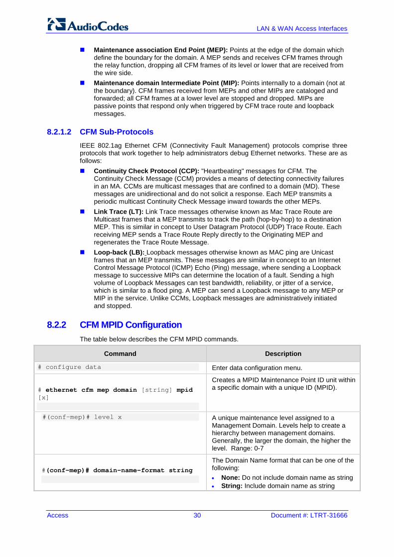
Maintenance association End Point (MEP): Points at the edge of the domain which define the boundary for the domain. A MEP sends and receives CFM frames through the relay function, dropping all CFM frames of its level or lower that are received from the wire side.
Maintenance domain Intermediate Point (MIP): Points internally to a domain (not at the boundary). CFM frames received from MEPs and other MIPs are cataloged and forwarded; all CFM frames at a lower level are stopped and dropped. MIPs are passive points that respond only when triggered by CFM trace route and loopback messages.
8.2.1.2 CFM Sub-Protocols IEEE 802.1ag Ethernet CFM (Connectivity Fault Management) protocols comprise three protocols that work together to help administrators debug Ethernet networks. These are as follows: Continuity Check Protocol (CCP): "Heartbeating" messages for CFM. The
Continuity Check Message (CCM) provides a means of detecting connectivity failures in an MA. CCMs are multicast messages that are confined to a domain (MD). These messages are unidirectional and do not solicit a response. Each MEP transmits a periodic multicast Continuity Check Message inward towards the other MEPs.
Link Trace (LT): Link Trace messages otherwise known as Mac Trace Route are Multicast frames that a MEP transmits to track the path (hop-by-hop) to a destination MEP. This is similar in concept to User Datagram Protocol (UDP) Trace Route. Each receiving MEP sends a Trace Route Reply directly to the Originating MEP and regenerates the Trace Route Message.
Loop-back (LB): Loopback messages otherwise known as MAC ping are Unicast frames that an MEP transmits. These messages are similar in concept to an Internet Control Message Protocol (ICMP) Echo (Ping) message, where sending a Loopback message to successive MIPs can determine the location of a fault. Sending a high volume of Loopback Messages can test bandwidth, reliability, or jitter of a service, which is similar to a flood ping. A MEP can send a Loopback message to any MEP or MIP in the service. Unlike CCMs, Loopback messages are administratively initiated and stopped.
8.2.2 CFM MPID Configuration The table below describes the CFM MPID commands.
Command Description
# configure data Enter data configuration menu.
# ethernet cfm mep domain [string] mpid [x]
Creates a MPID Maintenance Point ID unit within a specific domain with a unique ID (MPID).
#(conf-mep)# level x A unique maintenance level assigned to a Management Domain. Levels help to create a hierarchy between management domains. Generally, the larger the domain, the higher the level. Range: 0-7
#(conf-mep)# domain-name-format string
The Domain Name format that can be one of the following: • None: Do not include domain name as string • String: Include domain name as string

Configuration Guide 8. Ethernet OAM
Version 6.8 31 Mediant MSBR
Command Description
#(conf-mep)# service string [string][number][vid]
Maintenance Association (MA) short name that can be one of the following: • number • string • vid
#(conf-mep)# link-state reflect Defines the CFM protocol to reflect the status of a LAN interface.
#(conf-mep)# interface [name]
WAN port that interfaces the maintenance domain and towards the other MEPs.
#(conf-mep)# continuity-check interval [interval-string]
“heartbeat” mechanism of the protocol, with adjustable interval. Possible values are: 100ms, 10m, 10ms, 10s,1m, 1s and 3ms
#(conf-mep)# exit Returns to the data menu.

Access 32 Document #: LTRT-31666
LAN & WAN Access Interfaces
This page is intentionally left blank.

Configuration Guide 9. Ethernet CFM Verification
Version 6.8 33 Mediant MSBR
9 Ethernet CFM Verification This chapter describes Ethernet CFM verification commands.
9.1.1 Show Data Ethernet CFM This command displays CFM interface information for local and remote MFPs and checks the results. Board_BS_5001# show data ethernet cfm Local MEPs: MPID VLAN RmtRDI MAC Remote XCON ---------------------------------------- 17 OK OK Error OK OK Remote MEPs: MPID Stat DomainName MAC Age Intf Port -------------------------------------------------------------------- 7 UP dima 10:05:ca:2d:8d:89 2s Up Down Board_BS_500# show data ethernet cfm legend Local MEPs: MPID VLAN RmtRDI MAC Remote XCON ---------------------------------------- 17 OK OK Error OK OK Error legend: VLAN : The local logical interface is down. RmtRDI: One of the remote MEPs is not receiving all CCMs. MAC : One of the remote MEPs has a blocked port status. Remote: There are no known remote MEPs. XCON : The MEP is receiving CCMs from different domains or services. Remote MEPs: MPID Stat DomainName MAC Age Intf Port -------------------------------------------------------------------- 7 UP dima 10:05:ca:2d:8d:89 6s Up Down Board_BS_500#

Access 34 Document #: LTRT-31666
LAN & WAN Access Interfaces
9.1.2 Ping Ethernet This command sends layer two queries to a destination domain and displays the results. Board_BS_500# ping ethernet mpid 7 domain dima (1/1) Reply from 10:05:ca:2d:8d:89, seq 1 (2/2) Reply from 10:05:ca:2d:8d:89, seq 2 (3/3) Reply from 10:05:ca:2d:8d:89, seq 3 (4/4) Reply from 10:05:ca:2d:8d:89, seq 4 (5/5) Reply from 10:05:ca:2d:8d:89, seq 5 (6/6) Reply from 10:05:ca:2d:8d:89, seq 6 6 sent, 6 received. Board_BS_500#
9.1.3 Traceroute Ethernet This command traces the Ethernet route for a specific destination domain. Board_BS_500# traceroute ethernet mpid 7 domain dima Trace reply from 10:05:ca:2d:8d:89 TTL 63 Board_BS_500#
9.1.4 Show Remote Ethernet CFM Maintenance-points This command displays the remote Ethernet CFM Maintenance points for the local MEP. Aut_router#show ethernet cfm maintenance-points local Local MEPs: -------------------------------------------------------------------------------- MPID Domain Name Lvl MacAddress Type CC Ofld Domain Id Dir Port Id MA Name SrvcInst Source EVC name -------------------------------------------------------------------------------- 7 dima 7 1005.ca2d.8d89 Port Y No dima Down Gi0/1 none test N/A Static N/A Total Local MEPs: 1 Local MIPs: None Aut_router#show ethernet cfm maintenance-points remote --------------------------------------------------------------------------------

Configuration Guide 9. Ethernet CFM Verification
Version 6.8 35 Mediant MSBR
MPID Domain Name MacAddress IfSt PtSt Lvl Domain ID Ingress RDI MA Name Type Id SrvcInst EVC Name Age -------------------------------------------------------------------------------- 17 dima 0090.8f57.954f Up N/A 7 dima Gi0/1 - test Port none N/A N/A 8s Total Remote MEPs: 1 Aut_router#

Access 36 Document #: LTRT-31666
LAN & WAN Access Interfaces
This page is intentionally left blank.

Configuration Guide 10. Y.1731: OAM Functions and Mechanisms for Ethernet based Networks
Version 6.8 37 Mediant MSBR
10 Y.1731: OAM Functions and Mechanisms for Ethernet based Networks This chapter describes the implementation of Y.1731 recommendations for OAM Functions and Mechanisms for Ethernet based Networks.
10.1 Description Y.1731 is used for user-plane OAM functionality in Ethernet networks (Operations, Administration, and Maintenance), point-to-point connections and multipoint connectivity in the ETH layer. Y.1731 includes the following mechanisms: Fault Management Performance Management The IEEE 802.1ag is based in line with ITU-T recommendation Y.1731, which also addresses the following performance management issues: Ethernet alarm indication signal (ETH-AIS) Ethernet locked signal (ETH-LCK) Frame loss measurement (ETH-LM) Frame delay measurement (ETH-DM)
10.2 Functions for Fault Management The source MAC address for all OAM frames is always a unicast MAC address. The destination MAC address may be either a unicast or a multicast address depending on the message type and application.
10.2.1 Alarm Indication Signal (AIS) Condition AIS provides an indication of service interruption. AIS is signaled by remotely connected peer MEPs to indicate a network fault.
Command Description
# configure data Enters Data configuration menu. # ethernet cfm ais domain [name] level ]1-7]
Configures to listen to the AIS signal in a specified domain and level.
# ais-period interval [1,60] (Sec) Configures the time to wait until the AIS state is cleared.
10.2.1.1 Ethernet Locked - Signal ETH-LCK LCK is signaled to indicate an administrative lock condition.
Command Description
# configure data Enters data configuration menu. # ethernet cfm lck level [1-7] Configures the LCK state for a specified level. # lck-period interval [1-60](Sec) Configures the time to wait until the sending of
the LCK (fault) state is ceased.

Access 38 Document #: LTRT-31666
LAN & WAN Access Interfaces
Command Description
# configure data Enters data configuration menu.
# ethernet cfm lck start level [1-7] period [1-60]
Starts sending a LCK state for a specified level and period (sec).
# ethernet cfm lck stop level [1-7] period [1-60]
Stops sending and listening for changes in a LCK state.
An example CLI show output for the AIS and LCK state is displayed below:
Mediant 800 - MSBR# do show data ethernet cfm legend Local MEPs: MPID VLAN RmtRDI MAC Remote XCON RmtAIS RmtLCK -------------------------------------------------------- 18 OK OK OK Error OK OK OK
10.3 Functions for Performance Management (Y.1731) Y.1731 Performance Monitoring (PM) provides a standard ethernet PM function that includes measurement of ethernet frame delay, frame delay variation, frame loss, and frame throughput measurements, All of these monitors are specified in the ITU-T Y-1731 standard and interpreted by the Metro Ethernet Forum.
10.3.1 Set Frame Delay Measurement (ETH-DM) Frame delay measurement (ETH-DM) can be used for on-demand or proactive OAM to measure frame delay and frame delay variation. Frame delay and frame delay variation measurements are performed by sending periodic frames with ETH-DM information to the peer MEP and receiving frames with ETH-DM information from the peer MEP during a proactive measurement session and/or diagnostic interval. Each MEP may perform frame delay and frame delay variation measurements. When a MEP is enabled to generate frames with ETH-DM information, it periodically sends frames with ETH-DM information to its peer MEP in the same ME. When a MEP is enabled to generate frames with ETH-DM information, it also expects to receive frames with ETH-DM information from its peer MEP in the same ME.

Configuration Guide 10. Y.1731: OAM Functions and Mechanisms for Ethernet based Networks
Version 6.8 39 Mediant MSBR
10.3.1.1 1DM - One-way ETH-DM (using 1DM PDU) 1DM - MEP periodically transmits 1DM frames with the Transit Time Stamp value. The MEP uses a Data TLV when configured for measuring delay and delay variation for different frame sizes.
10.3.1.1.1 Reception
When configured for dual-ended ETH-DM, a MEP, upon receiving a valid 1DM frame, uses the following values to generate a one-way frame delay measurement. A 1DM frame with a valid MEG level and a destination MAC address equal to the receiving MEP's MAC address or multicast Class 1 MAC address is considered to be a valid 1DM frame. These values serve as input to the one-way frame delay variation measurement.
Command Description
# configure data Enters data configuration menu.
# ethernet y1731 1dm domain [name]
mpid [id] level [1-7]
Starts sending 1DM frame for specified domain, MPID and level.
An example of the CLI show output for the 1DM results is displayed below: # show data ethernet y1731 onedm 1DM Statistics: MPID Delay(Nano Sec) ------------------------------- 20 2678.000
10.3.1.2 DMM/DMR - Two-way ETH-DM (using DMM and DMR PDUs) When configured for single-ended ETH-DM, a MEP periodically transmits DMM frames with the Transmit Time Stamp value. The MEP uses a Data TLV when configured for measuring delay and delay variation for different frame sizes.
10.3.1.3 DMM Reception and DMR Transmission Whenever a valid DMM frame is received by a MEP, a DMR frame is generated and transmitted to the initiating MEP.
Note: A valid DMM packet has a MEG level and a destination MAC address that is the same as the MEP.
Command Description
# configure data Enters the Data configuration menu.
# ethernet y1731 loss lmm domain [name] service [name] mpid [id] level [1-7] source mpid [id]
Starts sending a DDM frame for specified Domain, MPID and Level.

Access 40 Document #: LTRT-31666
LAN & WAN Access Interfaces
An example CLI show output with DMM/DMR results is displayed below: show data ethernet y1731 lmm LMM LMR Statistics: DstAddr SrcAddr Frame Loss Loss Rate --------------------------------------------------------------- 00:90:8f:4f:5a:87 00:90:8f:5e:99:f3 5 0.000000001 00:90:8f:4f:5a:87 00:90:8f:5e:99:f3 1 0.000000000 00:90:8f:4f:5a:87 00:90:8f:5e:99:f3 2 0.222222222 00:90:8f:4f:5a:87 00:90:8f:5e:99:f3 1 0.000000000 00:90:8f:4f:5a:87 00:90:8f:5e:99:f3 1 0.000000000 00:90:8f:4f:5a:87 00:90:8f:5e:99:f3 1 0.000000000 00:90:8f:4f:5a:87 00:90:8f:5e:99:f3 1 0.000000000 00:90:8f:4f:5a:87 00:90:8f:5e:99:f3 1 0.000000000 00:90:8f:4f:5a:87 00:90:8f:5e:99:f3 1 0.000000000 00:90:8f:4f:5a:87 00:90:8f:5e:99:f3 1 0.000000000 00:90:8f:4f:5a:87 00:90:8f:5e:99:f3 1 0.000000000 00:90:8f:4f:5a:87 00:90:8f:5e:99:f3 1 0.000000000 00:90:8f:4f:5a:87 00:90:8f:5e:99:f3 1 0.000000000 00:90:8f:4f:5a:87 00:90:8f:5e:99:f3 1 0.000000000 00:90:8f:4f:5a:87 00:90:8f:5e:99:f3 2 0.200000000 00:90:8f:4f:5a:87 00:90:8f:5e:99:f3 1 0.000000000 00:90:8f:4f:5a:87 00:90:8f:5e:99:f3 1 0.000000000 00:90:8f:4f:5a:87 00:90:8f:5e:99:f3 1 0.000000000 00:90:8f:4f:5a:87 00:90:8f:5e:99:f3 1 0.000000000 00:90:8f:4f:5a:87 00:90:8f:5e:99:f3 1 0.000000000 00:90:8f:4f:5a:87 00:90:8f:5e:99:f3 1 0.000000000 00:90:8f:4f:5a:87 00:90:8f:5e:99:f3 1 0.000000000 00:90:8f:4f:5a:87 00:90:8f:5e:99:f3 1 0.000000000 00:90:8f:4f:5a:87 00:90:8f:5e:99:f3 1 0.000000000 00:90:8f:4f:5a:87 00:90:8f:5e:99:f3 2 0.181818182 00:90:8f:4f:5a:87 00:90:8f:5e:99:f3 1 0.000000000 00:90:8f:4f:5a:87 00:90:8f:5e:99:f3 1 0.000000000 00:90:8f:4f:5a:87 00:90:8f:5e:99:f3 1 0.000000000 00:90:8f:4f:5a:87 00:90:8f:5e:99:f3 1 0.000000000 00:90:8f:4f:5a:87 00:90:8f:5e:99:f3 1 0.000000000 00:90:8f:4f:5a:87 00:90:8f:5e:99:f3 1 0.000000000 00:90:8f:4f:5a:87 00:90:8f:5e:99:f3 1 0.000000000 00:90:8f:4f:5a:87 00:90:8f:5e:99:f3 1 0.000000000 00:90:8f:4f:5a:87 00:90:8f:5e:99:f3 1 0.000000000 00:90:8f:4f:5a:87 00:90:8f:5e:99:f3 2 0.166666667 00:90:8f:4f:5a:87 00:90:8f:5e:99:f3 1 0.000000000 00:90:8f:4f:5a:87 00:90:8f:5e:99:f3 1 0.000000000 00:90:8f:4f:5a:87 00:90:8f:5e:99:f3 1 0.000000000 00:90:8f:4f:5a:87 00:90:8f:5e:99:f3 1 0.000000000 00:90:8f:4f:5a:87 00:90:8f:5e:99:f3 1 0.000000000 00:90:8f:4f:5a:87 00:90:8f:5e:99:f3 1 0.000000000 00:90:8f:4f:5a:87 00:90:8f:5e:99:f3 1 0.000000000 00:90:8f:4f:5a:87 00:90:8f:5e:99:f3 1 0.000000000 00:90:8f:4f:5a:87 00:90:8f:5e:99:f3 1 0.000000000 00:90:8f:4f:5a:87 00:90:8f:5e:99:f3 2 0.153846154

Configuration Guide 10. Y.1731: OAM Functions and Mechanisms for Ethernet based Networks
Version 6.8 41 Mediant MSBR
00:90:8f:4f:5a:87 00:90:8f:5e:99:f3 1 0.000000000 00:90:8f:4f:5a:87 00:90:8f:5e:99:f3 1 0.000000000 00:90:8f:4f:5a:87 00:90:8f:5e:99:f3 1 0.000000000 00:90:8f:4f:5a:87 00:90:8f:5e:99:f3 1 0.000000000 00:90:8f:4f:5a:87 00:90:8f:5e:99:f3 1 0.000000000 00:90:8f:4f:5a:87 00:90:8f:5e:99:f3 1 0.000000000 00:90:8f:4f:5a:87 00:90:8f:5e:99:f3 1 0.000000000 00:90:8f:4f:5a:87 00:90:8f:5e:99:f3 1 0.000000000 00:90:8f:4f:5a:87 00:90:8f:5e:99:f3 1 0.000000000 00:90:8f:4f:5a:87 00:90:8f:5e:99:f3 1 0.000000000 00:90:8f:4f:5a:87 00:90:8f:5e:99:f3 2 0.000000001 00:90:8f:4f:5a:87 00:90:8f:5e:99:f3 1 0.000000000 Start time: Wed May 25 10:50:22 2016 End time: Wed May 25 10:51:21 2016 Number of measurements initiated: 56 Number of measurements completed: 57 Forward Number of Observations 57 Available indicators: 57 Unavailable indicators: 0 Tx frame count: 127 Rx frame count: 3 Min Avg Max - (FLR): 0 0.015940573 0.222222222 Cumulative - (FLR): 0.924553240 Timestamps forward: Min - Wed May 25 10:50:22 2016 Max - Wed May 25 10:51:21 2016 Backword Number of Observations 57 Available indicators: 57 Unavailable indicators: 0 Tx frame count: 127 Rx frame count: 3 Min Avg Max - (FLR): 0 0.015940573 0.222222222 Cumulative - (FLR): 0.924553240 Timestamps forward: Min - Wed May 25 10:50:22 2016 Max - Wed May 25 10:51:21 2016

Access 42 Document #: LTRT-31666
LAN & WAN Access Interfaces
10.4 EFM OAM
10.4.1 Description Ethernet in the first mile (EFM) refers to using one of the Ethernet family of computer network protocols between a telecommunications company and a customer's premises. From the customer's point of view, it is their "first" mile, although from the access network's point of view it is known as the "last mile". A working group of the Institute of Electrical and Electronics Engineers (IEEE) produced the standards known as IEEE 802.3ah-2004, which were later included in the overall standard IEEE 802.3-2008. Although it is often used for businesses, it can also be known as Ethernet to the Home (ETTH).
10.4.2 Features The OAM features as defined by IEEE 802.3ah “Ethernet in the First Mile” which includes discovery, Link Monitoring, Remote Fault Detection, Remote Loopback, and Cisco Proprietary Extensions.
10.4.2.1 Discovery Discovery is the first phase of the Ethernet OAM. This phase identifies the devices in the network and their OAM capabilities. Discovery uses information OAM PDUs. During the discovery phase, the following information is advertised within periodic information OAM PDUs: OAM mode: Conveyed to the remote OAM entity. This mode can be either active or
passive and can be used to determine device functionality. Note: The MSBR is always in the passive mode.
OAM configuration (capabilities): Advertises the capabilities of the local OAM entity. A peer can use this information to determine which functions are supported and accessible; for example, loopback capability.
OAM PDU configuration: Includes the maximum OAM PDU size for receipt and delivery. This information along with the rate limit of 10 frames per second can be used to limit the bandwidth allocated to OAM traffic.
Platform identity: A combination of an organization unique identifier (OUI) and 32-bits of vendor-specific information. OUI allocation, controlled by the IEEE, is typically the first three bytes of a MAC address.
Discovery includes an optional phase in which the local station can accept or reject the configuration of the peer OAM entity. For example, a node may require that its partner support loopback capability to be accepted into the management network. These policy decisions may be implemented as vendor-specific extensions.
10.4.2.2 Link Monitoring
Link monitoring in Ethernet OAM detects and indicates link faults under a variety of conditions. Link monitoring uses the event notification OAM PDU and sends events to the remote OAM entity when problems are detected on the link. The error events include the following: Error Symbol Period (error symbols per second): The number of symbol errors
that occurred during a specified period that has exceeded a threshold. These errors are coding symbol errors.
Error Frame (error frames per second): The number of frame errors detected during a specified period that has exceeded a threshold.
Error Frame Period (error frames per n frames): The number of frame errors within the last n frames that has exceeded a threshold.
Configuration Guide 10. Y.1731: OAM Functions and Mechanisms for Ethernet based Networks
Version 6.8 43 Mediant MSBR
Error Frame Seconds Summary (error seconds per m seconds): The number of error seconds (1-second intervals with at least one frame error) within the last m seconds that has exceeded a threshold.
10.4.2.3 Remote Failure Indication Faults in Ethernet connectivity that are caused by slowly deteriorating quality are difficult to detect. Ethernet OAM provides a mechanism for an OAM entity to convey these failure conditions to its peer via specific flags in the OAM PDU. The following failure conditions can be communicated: Link Fault: Loss of signal is detected by the receiver; for example, the peer's laser is
malfunctioning. A link fault is sent once per second in the information OAM PDU. Link faults only apply when the physical sublayer is capable of independently transmitting and receiving signals.
Dying Gasp: An unrecoverable condition has occurred; for example, a power failure. This type of condition is vendor specific. A notification about the condition may be sent immediately and continuously.
Critical Event: An unspecified critical event has occurred. This type of event is vendor-specific. A critical event may be sent immediately and continuously.
10.4.2.4 Remote Loopback An OAM entity can put its remote peer into loopback mode using the loopback control OAM PDU. Loopback mode helps an administrator ensure the quality of links during installation or when troubleshooting. In loopback mode, every frame received is transmitted back on the same port except for OAM PDUs and pause frames. The periodic exchange of OAM PDUs must continue during the loopback state to maintain the OAM session. The loopback command is acknowledged by responding with an information OAM PDU with the loopback state indicated in the state field. This acknowledgement allows an administrator, for example, to estimate if a network segment can satisfy a service-level agreement. Acknowledgement makes it possible to test delay, jitter, and throughput.
Note: For the MSBR, loopback is supported for the GigaEthernet/Fiber interfaces only and not for the EFM interface.
10.4.2.5 OAM Messages Ethernet OAM messages or OAM PDUs are standard length, untagged Ethernet frames within the normal frame length bounds of 64 to 1518 bytes. The maximum OAM PDU frame size exchanged between two peers is negotiated during the discovery phase. OAM PDUs always have the destination address of slow protocols (0180.c200.0002) and an Ether type of 8809. OAM PDUs do not go beyond a single hop and have a hard-set maximum transmission rate of 10 OAM PDUs per second. Some OAM PDU types may be transmitted multiple times to increase the likelihood that they will be successfully received on a deteriorating link. Four types of OAM messages are supported: Information OAM PDU: A variable-length OAM PDU that is used for discovery. This
OAM PDU includes local, remote, and organization-specific information. Event notification OAM PDU: A variable-length OAM PDU that is used for link
monitoring. This type of OAM PDU may be transmitted multiple times to increase the chance of a successful receipt; for example, in the case of high-bit errors. Event notification OAM PDUs also may include a time stamp when generated.

Access 44 Document #: LTRT-31666
LAN & WAN Access Interfaces
Loopback control OAM PDU: An OAM PDU fixed at 64 bytes in length that is used to enable or disable the remote loopback command.
Vendor-specific OAM PDU: A variable-length OAM PDU that allows the addition of vendor-specific extensions to OAM.
10.4.3 Configuration The table below shows how to configure OAM on a Gigabit Ethernet, EFM or Fiber interface.
Command Description
# configure data Enters Data configuration menu. interface giga/efm/fiber slot/port Enters the Interface command mode. ethernet oam Enables OAM on the interface ethernet oam link-monitor capable Enables Link monitor supported ethernet oam link-monitor frame Enables Link Monitor Errored Frame Event ethernet oam link-monitor frame threshold xxx
Changes the Link monitor threshold [1- 65535]
ethernet oam link-monitor frame window xxx
Changes the Link Monitor Frame Window in seconds [10-60] Sec,
ethernet oam remote-loopback capable
EFM OAM supported remote loopbacks
ethernet oam timeout [value] Sets timeout value in seconds [5-30]
Enabling Ethernet OAM: Mediant 800B - MSBR# configure data Mediant 800B - MSBR(config-data)# interface gigabitethernet 0/0 Mediant 800B - MSBR(conf-if-GE 0/0)# ethernet oam Mediant 800B - MSBR(conf-if-GE 0/0)#
Configuring Ethernet OAM link-monitor capability and parameters: Mediant 800B - MSBR# configure data Mediant 800B - MSBR(config-data)# interface gigabitethernet 0/0 Mediant 800B - MSBR(conf-if-GE 0/0)# ethernet oam Mediant 800B - MSBR(conf-if-GE 0/0)# ethernet oam link-monitor capable Mediant 800B - MSBR(conf-if-GE 0/0)# ethernet oam link-monitor frame threshold 5 Mediant 800B - MSBR(conf-if-GE 0/0)# ethernet oam link-monitor frame window 10 Mediant 800B - MSBR(conf-if-GE 0/0)#
Configuring Ethernet OAM link-monitor remote-loopback capability: Mediant 800B - MSBR# conf data Mediant 800B - MSBR(config-data)# interface gigabitethernet 0/0 Mediant 800B - MSBR(conf-if-GE 0/0)# ethernet oam Mediant 800B - MSBR(conf-if-GE 0/0)# ethernet oam remote-loopback capable

Configuration Guide 10. Y.1731: OAM Functions and Mechanisms for Ethernet based Networks
Version 6.8 45 Mediant MSBR
Mediant 800B - MSBR(conf-if-GE 0/0)# exit Mediant 800B - MSBR(config-data)#
Configuring Ethernet OAM link timeout parameter: Mediant 800B - MSBR# conf data Mediant 800B - MSBR(config-data)# interface gigabitethernet 0/0 Mediant 800B - MSBR(conf-if-GE 0/0)# ethernet oam Mediant 800B - MSBR(conf-if-GE 0/0)# ethernet oam timeout 5 Mediant 800B - MSBR(conf-if-GE 0/0)#
Configuring Ethernet OAM loopback action: Mediant 800B - MSBR# debug ethernet loopback interface gigabitethernet 0/0 Interface is in LOOPBACK mode. You will be unable to pass traffic across that interface.
10.4.4 Show Commands The following table describes the Ethernet OAM show commands.
Command Description
show data ethernet oam brief Show Ethernet OAM brief show data ethernet oam configuration
Show Ethernet OAM configuration
show data ethernet oam counters Show Ethernet OAM counters show data ethernet oam interface giga/fiber/efm slot/port
Show Ethernet OAM status per interface
show data ethernet oam status Show Ethernet OAM status
The following example includes CLI output for the above commands: Mediant 800B - MSBR# show data ethernet oam brief Local Remote Interface Mode Capability MAC Address Vendor(oui) Mode capability Gi 0/0 Passive L R V 10:05:CA:2D:8D:89 0C Active L R Fiber 0/3 Not enabled Capability codes: L - Link Monitor, R - Remote Loopback, U - Unidirection, V - Variable Retrieval Mediant 800B - MSBR# Mediant 800B - MSBR# show data ethernet oam configuration Interface GigabitEthernet 0/0: ============================== Local client ------------ Configurations: Mode: Passive

Access 46 Document #: LTRT-31666
LAN & WAN Access Interfaces
Time Out: 5 Sec Unidirection : Not supported Link monitor : Supported Remote loopback : Supported Variable rerievel : Not supported Link monitor Errored Symbol Period Event Enabled: Window = 30 Sec Threshold = 65535 Symbols Link monitor Errored Frame Event Enabled: Window = 10 Sec Threshold = 5 Frames Status: Port status: Operational Loopback status: Operational Remote client ------------- MAC address: 10:5:CA:2D:8D:89 Vendor(oui): 0C Configurations: Mode: Active Unidirection : Not supported Link monitor : Supported Remote loopback : Supported MIB variable retrieval : Not supported ================================================================= Mediant 800B - MSBR# show data ethernet oam counters GigabitEthernet 0/0 ============================== Counters: ---------------------------- Total PDU packets: 476391 ERRORED PDU packets: 0 Total_tx_packet: 234813 Total_rx_packet: 241578 Information OAMPDU Tx: 234813 Information OAMPDU Rx: 241578 Event Notification OAMPDU Tx: 0 Event Notification OAMPDU Rx: 0 Duplicate Event Notification OAMPDU TX: 0 Duplicate Event Notification OAMPDU RX: 0 Loopback Control OAMPDU Tx: 0 Loopback Control OAMPDU Rx: 0 Variable Request OAMPDU Tx: 0 Variable Request OAMPDU Rx: 0 Variable Response OAMPDU Tx: 0 Variable Response OAMPDU Rx: 0 Local Faults: ---------------------------- Link Fault records 0 Dying Gasp records 0 Critical Event records 0 Remote Faults:

Configuration Guide 10. Y.1731: OAM Functions and Mechanisms for Ethernet based Networks
Version 6.8 47 Mediant MSBR
---------------------------- Link Fault records 0 Dying Gasp records 0 Critical Event records 0 Ethernet OAM is not enabled on FIBER 0/3. ============================== Mediant 800B - MSBR# Mediant 800B - MSBR# show data ethernet oam status GigabitEthernet 0/0 ============================== Runtime Settings: ---------------------------- local_pdu: ANY local_mux: FWD local_par: FWD local_link_status: UP local_satisfied: Yes local_stable: Yes enter_loopback: No lost_link_timer: Runing remote_state_valid: Yes remote_stable: Yes remote_evaluating: Yes State Machine: ---------------------------- state: SEND_ANY Ethernet OAM is not enabled on FIBER 0/3. Mediant 800B - MSBR#

Access 48 Document #: LTRT-31666
LAN & WAN Access Interfaces
This page is intentionally left blank.

Configuration Guide 11. Multiple DSL Connection
Version 6.8 49 Mediant MSBR
11 Multiple DSL Connection Multilink PPP (MLPPP) is a communications protocol that enables a PC to use two PPP communications ports as if they were a single port of greater bandwidth. MLPPP can be used with other communication media such as telephone dial-up modems, cable modems, fiber optic systems or satellite Internet connections. PPP is a full-duplex protocol for communication between computers using a serial interface. PPP offers error correction and can handle synchronous as well as asynchronous data.
11.1 Examples This example shows how to connect MSBR through SHDSL and VDSL at the same time.
Figure 11-1: Multiple DSL Example
VDSL connection
DSL 0/2
Service Provider
MPLSInternet Network
MPLSLAN
Client
MPLS
Service Provider
Internet NetworkSHDSL
DSLAM(CO)
MSBR(CPE)
1. Configure an SHDSL connection on the ATM mode:
# configure data (config-data)# interface shdsl 0/1 (conf-if-shdsl 0/1)# mode atm (conf-if-shdsl 0/1)# no group 1 (conf-if-shdsl 0/1)# no group 2 (conf-if-shdsl 0/1)# no group 3 (conf-if-shdsl 0/1)# group 0 (conf-if-shdsl-0)# termination cpe (conf-if-shdsl-0)# linerate auto (conf-if-shdsl-0)# annex A (conf-if-shdsl-0)# caplist-style new (conf-if-shdsl-0)# pairs 0 (conf-if-shdsl-0)# exit (conf-if-shdsl 0/1)# exit
2. Configure the DSL interface on the VDSL mode with EFM interface: (config-data)# interface dsl 0/2 (conf-if-dsl 0/2)# mode vdsl (conf-if-dsl 0/2)# no shutdown (conf-if-dsl 0/2)# exit (config-data)# interface EFM 0/2 (conf-if-efm 0/2)# no ip address (conf-if-efm 0/2)# mtu 1524 (conf-if-efm 0/2)# desc "VDSL" (conf-if-efm 0/2)# no service dhcp (conf-if-efm 0/2)# ip dns server auto

Access 50 Document #: LTRT-31666
LAN & WAN Access Interfaces
(conf-if-efm 0/2)# no shutdown (conf-if-efm 0/2)# exit
3. Configure the ATM interface to work with SHDSL: (config-data)# interface ATM 0/0 (conf-atm0/0)# encapsulation ethoa-snap (conf-atm0/0)# pvc 0/32 (conf-atm0/0)# ubr (conf-atm0/0)# ip address 192.168.27.3 255.255.255.0 (conf-atm0/0)# ip dns server auto (conf-atm0/0)# no napt (conf-atm0/0)# no firewall enable (conf-atm0/0)# mtu auto (conf-atm0/0)# exit
4. Secure the EFM interface using PPPoE: (config-data)# interface pppoe 0 (conf-pppoe-0)# no firewall enable (conf-pppoe-0)# no napt (conf-pppoe-0)# mtu auto (conf-pppoe-0)# ppp user acl119@014 pass F3YpKykvKSs= (conf-pppoe-0)# ppp authentication chap (conf-pppoe-0)# ppp authentication ms-chap (conf-pppoe-0)# ppp authentication ms-chap-v2 (conf-pppoe-0)# ppp authentication pap (conf-pppoe-0)# ppp lcp-echo 6 5 (conf-pppoe-0)# ip dns server auto (conf-pppoe-0)# underlying EFM 0/2 (conf-pppoe-0)# no shutdown (conf-pppoe-0)# exit
5. Configure a primary and secondary IP route: (config-data)# ip route 0.0.0.0 0.0.0.0 PPPOE 0 1 [Primary IP Route] (config-data)# ip route 192.168.27.0 255.255.255.0 ATM 0/0 2 [Secondary IP Route]

Configuration Guide 12. E1/T1 (PRI)
Version 6.8 51 Mediant MSBR
12 E1/T1 (PRI) Primary Rate Interface (PRI) is a standardized telecommunications service level within the Integrated Services Digital Network (ISDN) specification for carrying voice and data transmissions between a network and a user. PRI is the standard for providing telecommunication services to offices. It is based on the T-carrier (T1) line in the US and Canada, and the E-carrier (E1) line in Europe. The T1 line consists of 24 channels, while an E1 has 32. PRI provides a varying number of channels depending on the standards in the country of implementation. In North America and Japan, it consists of 23xB (B channels). In Europe and Australia it is 30xB-Channel + 1xD-Channel on an E1 2.048 Mbit/s. One timeslot on the E1 is used for synchronization purposes and is not considered to be a B or D channel.
Command Description
# configure data Enter data configuration menu.
(config-data)# interface t1/e1 slot/port
Enter the E1/T1 interface command mode.
(config-if-t1 slot/port)# line-code [b8zs| b6zs|]
b8zs: Commonly used in the North American T1 (Digital Signal 1) 1.544 Mbit/s line code.
b6zs: same as b8zs, but only for T2 (6.312MB).
(config-if-t1 slot/port)# framing-method [sf|esf]
Frame synchronization is necessary to identify the timeslots within each 24-channel frame. Synchronization takes place by allocating a framing, or 193rd bit. This results in 8 kbit/s of framing data, for each framing type. Because this 8-kbit/s channel is used by the transmitting equipment as overhead. sf: super frame consists of twelve consecutive
193-bit frames. esf: Extended Super Frame consists of
twenty-four consecutive 193-bit frames of data. Due to the unique bit sequences exchanged, the framing schemes are not compatible with each other.
(config-if-t1 slot/port)# clock-source inline
T1 ports synchronize with outside clock source provide.
(config-if-t1 0/0)# channel-group 1-24
Configure which timeslots should be used.
(config-if-t1 0/0)# line-buildout-loss [Number]
LBO compensates for the loss in decibels based on the distance from the device to the first repeater in the circuit. A longer distance from the device to the repeater requires that the signal strength on the circuit be boosted to compensate for loss over that distance.
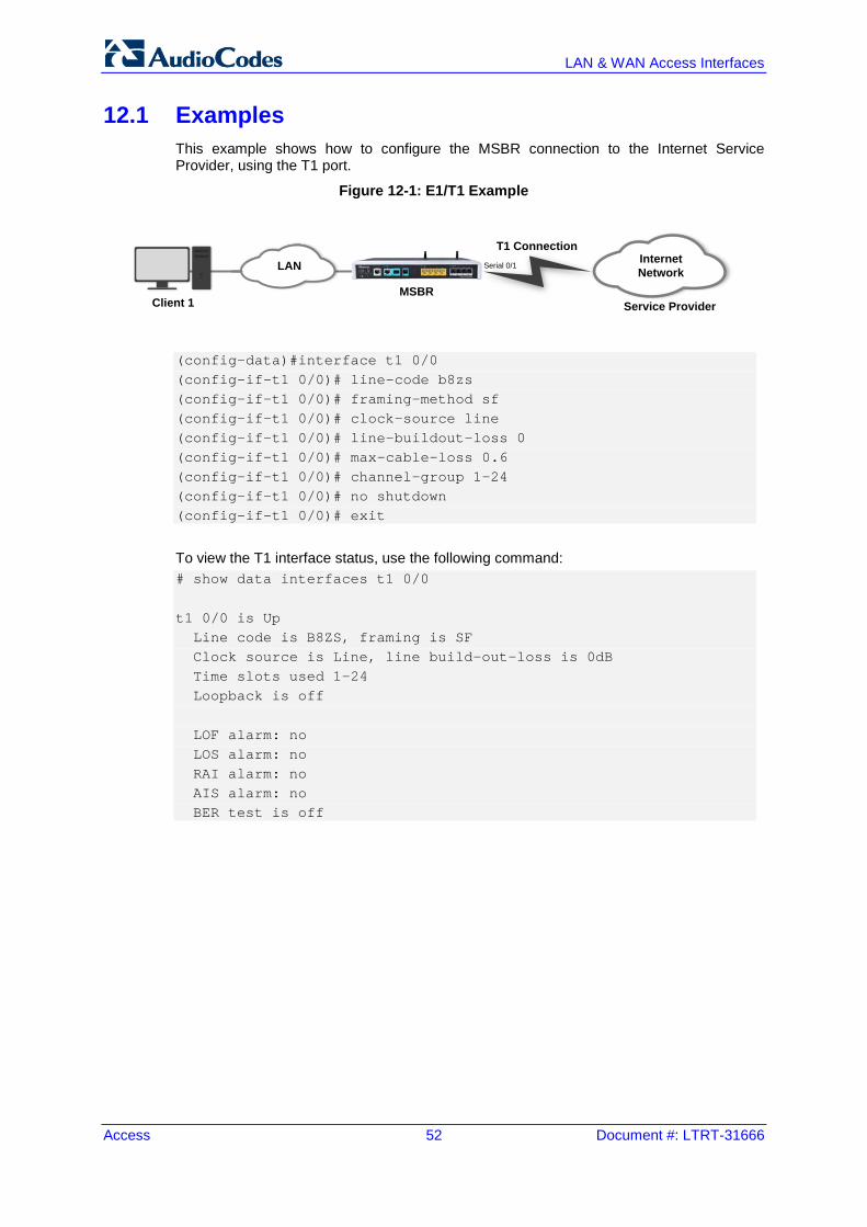
Access 52 Document #: LTRT-31666
LAN & WAN Access Interfaces
12.1 Examples This example shows how to configure the MSBR connection to the Internet Service Provider, using the T1 port.
Figure 12-1: E1/T1 Example
(config-data)#interface t1 0/0 (config-if-t1 0/0)# line-code b8zs (config-if-t1 0/0)# framing-method sf (config-if-t1 0/0)# clock-source line (config-if-t1 0/0)# line-buildout-loss 0 (config-if-t1 0/0)# max-cable-loss 0.6 (config-if-t1 0/0)# channel-group 1-24 (config-if-t1 0/0)# no shutdown (config-if-t1 0/0)# exit
To view the T1 interface status, use the following command: # show data interfaces t1 0/0 t1 0/0 is Up Line code is B8ZS, framing is SF Clock source is Line, line build-out-loss is 0dB Time slots used 1-24 Loopback is off LOF alarm: no LOS alarm: no RAI alarm: no AIS alarm: no BER test is off
Client 1MSBR
Serial 0/1MPLSLAN
Service Provider
MPLSInternet Network
T1 Connection
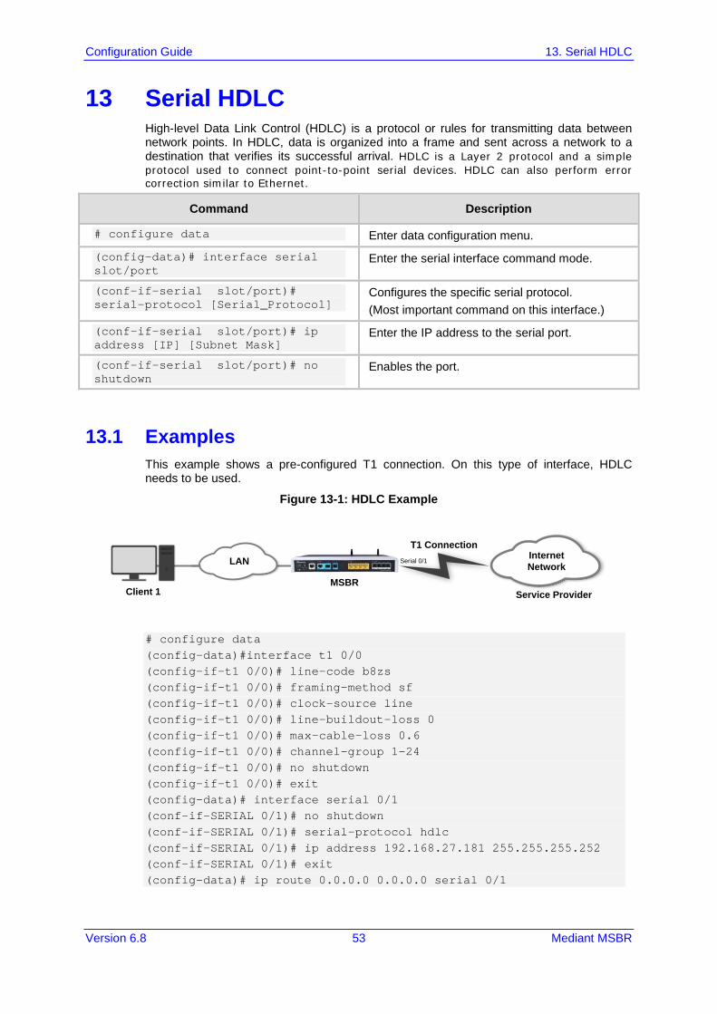
Configuration Guide 13. Serial HDLC
Version 6.8 53 Mediant MSBR
13 Serial HDLC High-level Data Link Control (HDLC) is a protocol or rules for transmitting data between network points. In HDLC, data is organized into a frame and sent across a network to a destination that verifies its successful arrival. HDLC is a Layer 2 protocol and a simple protocol used to connect point-to-point serial devices. HDLC can also perform error correction similar to Ethernet.
Command Description
# configure data Enter data configuration menu.
(config-data)# interface serial slot/port
Enter the serial interface command mode.
(conf-if-serial slot/port)# serial-protocol [Serial_Protocol]
Configures the specific serial protocol. (Most important command on this interface.)
(conf-if-serial slot/port)# ip address [IP] [Subnet Mask]
Enter the IP address to the serial port.
(conf-if-serial slot/port)# no shutdown
Enables the port.
13.1 Examples This example shows a pre-configured T1 connection. On this type of interface, HDLC needs to be used.
Figure 13-1: HDLC Example
# configure data (config-data)#interface t1 0/0 (config-if-t1 0/0)# line-code b8zs (config-if-t1 0/0)# framing-method sf (config-if-t1 0/0)# clock-source line (config-if-t1 0/0)# line-buildout-loss 0 (config-if-t1 0/0)# max-cable-loss 0.6 (config-if-t1 0/0)# channel-group 1-24 (config-if-t1 0/0)# no shutdown (config-if-t1 0/0)# exit (config-data)# interface serial 0/1 (conf-if-SERIAL 0/1)# no shutdown (conf-if-SERIAL 0/1)# serial-protocol hdlc (conf-if-SERIAL 0/1)# ip address 192.168.27.181 255.255.255.252 (conf-if-SERIAL 0/1)# exit (config-data)# ip route 0.0.0.0 0.0.0.0 serial 0/1
Client 1MSBR
Serial 0/1MPLSLAN
Service Provider
MPLSInternet Network
T1 Connection

Access 54 Document #: LTRT-31666
LAN & WAN Access Interfaces
To view the serial interface status, use the following command: # show data interface serial 0/1 SERIAL 0/0 is Connected Underlying hardware is interface T1 0/1 Protocol encapsulation is HDLC IP address is 192.168.27.182 netmask is 255.255.255.252 MTU is 0 bytes Available bandwidth is 1536 kbps 149 input packets, 57655 bytes 0 dropped input packets 0 output packets, 0 bytes 0 dropped output packets
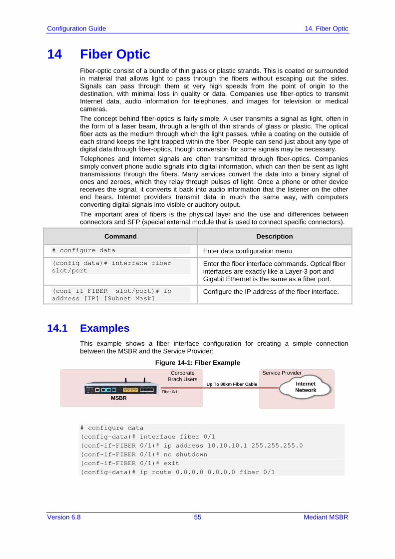
Configuration Guide 14. Fiber Optic
Version 6.8 55 Mediant MSBR
14 Fiber Optic Fiber-optic consist of a bundle of thin glass or plastic strands. This is coated or surrounded in material that allows light to pass through the fibers without escaping out the sides. Signals can pass through them at very high speeds from the point of origin to the destination, with minimal loss in quality or data. Companies use fiber-optics to transmit Internet data, audio information for telephones, and images for television or medical cameras. The concept behind fiber-optics is fairly simple. A user transmits a signal as light, often in the form of a laser beam, through a length of thin strands of glass or plastic. The optical fiber acts as the medium through which the light passes, while a coating on the outside of each strand keeps the light trapped within the fiber. People can send just about any type of digital data through fiber-optics, though conversion for some signals may be necessary. Telephones and Internet signals are often transmitted through fiber-optics. Companies simply convert phone audio signals into digital information, which can then be sent as light transmissions through the fibers. Many services convert the data into a binary signal of ones and zeroes, which they relay through pulses of light. Once a phone or other device receives the signal, it converts it back into audio information that the listener on the other end hears. Internet providers transmit data in much the same way, with computers converting digital signals into visible or auditory output. The important area of fibers is the physical layer and the use and differences between connectors and SFP (special external module that is used to connect specific connectors).
Command Description
# configure data Enter data configuration menu.
(config-data)# interface fiber slot/port
Enter the fiber interface commands. Optical fiber interfaces are exactly like a Layer-3 port and Gigabit Ethernet is the same as a fiber port.
(conf-if-FIBER slot/port)# ip address [IP] [Subnet Mask]
Configure the IP address of the fiber interface.
14.1 Examples This example shows a fiber interface configuration for creating a simple connection between the MSBR and the Service Provider:
Figure 14-1: Fiber Example
# configure data (config-data)# interface fiber 0/1 (conf-if-FIBER 0/1)# ip address 10.10.10.1 255.255.255.0 (conf-if-FIBER 0/1)# no shutdown (conf-if-FIBER 0/1)# exit (config-data)# ip route 0.0.0.0 0.0.0.0 fiber 0/1
MSBRFiber 0/1
Up To 80km Fiber Cable
Corporate Brach Users
Service Provider
MPLSInternet Network

Access 56 Document #: LTRT-31666
LAN & WAN Access Interfaces
This page is intentionally left blank.

Configuration Guide 15. WAN Failover
Version 6.8 57 Mediant MSBR
15 WAN Failover WAN failover is the process in which redundant WAN connections are configured to increase WAN uptime. To establish WAN failover, two separate WAN connections from different ISPs are required, which operate as primary and secondary connections. It is important that both WAN connections are from different ISPs so that if any problem arises in the WAN link from one ISP, the link from the second ISP can be used to establish a WAN connection. If both connections are from the same ISP and the ISP link goes down, both primary and secondary connections will fail, hence making WAN links unavailable even if WAN failover has been configured. When WAN failover is configured, the two WAN links are configured as active-passive connections. This means that under normal conditions (when no WAN downtime occurs), the primary WAN connection from one ISP is used to route all network traffic and it works as the active connection. In this case, the secondary connection from the other ISP remains in inactive/idle state (passive mode). When the primary WAN connection fails, the secondary connection automatically becomes active. This process is known as failover and is completely transparent to end-users. Once automatic failover occurs, network traffic is automatically routed through the secondary WAN connection. The secondary WAN connection remains active until the primary connection is up again to route the network traffic. As soon as the primary WAN connection becomes active, the secondary connection automatically becomes idle and enters passive mode. This process is known as WAN failback. The MSBR supports two methods for implementing WAN Failover: Cold Backup: In normal operation, only the primary WAN interface is up and active; all
the other backup WAN interfaces are down. When a failover occurs, only the newly active backup WAN interface is up.
Hot Backup: In normal operation, all WAN interfaces are up (primary and backup WAN interfaces), but only the primary WAN interface is active. When a failover occurs, the backup WAN interface becomes active (all the other WAN interfaces still remain in up-state).
Command Description
# configure data Enter data configuration menu.
(config-data)# backup-group [NAME] Create a backup WAN group with a specific name.
(backup-group)# description [WORD] Add a description for the backup group.
(backup-group)# exit Exit the backup-group state and return to the data configuration menu.
Configure a WAN backup group on the interface:
Command Description
# configure data Enter data configuration menu.
(config-data)# interface <physical_interface> slot/port
Enter the physical interface commands.
(conf-if-<int_name> Slot/Port)# backup backup monitoring group [Group_name] Priority [1/2/3]
Add an interface to the backup group and configure the group's priority. Note: Only one interface can be configured for each priority.
Configure a conditional route for Hot Backup:

Access 58 Document #: LTRT-31666
LAN & WAN Access Interfaces
Command Description
# configure data Enter data configuration menu.
(config-data)# track [track_ID] [icmpecho|icmpv6echo] [Network Destination] [Interface_track] [interval|retries]
track_ID: number identifier between 1 and 100 for track command.
icmpecho/icmpv6echo: choose between IPv4 and IPv6
Network Destination: Network commands tracks
Interface_track: interface on which command operates on
Interval: interval between probes Retries: how much time pass before track
goes down.
15.1 Examples
15.1.1 Cold Backup WAN Failover This example shows configuration for a Cold Backup WAN failover. The MSBR needs to be configured so that when the ATM connection fails, the 3G cellular modem becomes active.
Figure 15-1: WAN Failover Example
(config-data)# backup-group wan_failover (backup-group)# exit (config-data)# interface atm 0/0 (conf-if-atm0/0)# backup monitoring group wan_failover Priority 1 (config-data)# interface Cellular 0/0 (conf-if-cel0/0)# backup monitoring group wan_failover Priority 2
To view the active interface, use the following command: # show data backup-group Group Name: wan_failover
USB 3GCellular Modem
MSBR
AD
SL connection
ATM
connection
Service Provider
MPLSInternet Network

Configuration Guide 15. WAN Failover
Version 6.8 59 Mediant MSBR
Priority 1 atm 0/0 Priority 2 Cellular 0/0 Priority 3 Currently active interface: atm 0/0
After the atm 0/0 interface disconnects, the show command displays the following: # show data backup-group Group Name: wan_failover Priority 1 atm 0/0 Priority 2 Cellular 0/0 Priority 3 Currently active interface: Cellular 0/0
15.1.2 Hot Backup WAN Failover The following configuration example demonstrates Hot Backup and is based on the previous example. 1. Set the monitor routing for the primary default route:
(config-data)# track 1 icmpecho 8.8.8.8 atm 0/0 1 # first priority route – all traffic will be redirected to primary WAN (atm 0/0 interface). (config-data)# ip route 0.0.0.0 0.0.0.0 10.1.1.1 [Default Gateway] atm 0/0 track 1
2. Set the secondary WAN IP route: (config-data)# ip route 0.0.0.0 0.0.0.0 Cellular 0/0 100 # The metric 100 is set to create a secondary routing rule with lower priority, using Cellular 0/0 as the secondary WAN interface.
3. The traceroute command shows the path to the destination. The traceroute command shows how destination address 8.8.8.8 can be reached through the ATM interface. When the ATM interface is down, the destination 8.8.8.8 is reached through the cellular interface. # ATM is the active WAN interface: # traceroute 8.8.8.8 10.1.1.1 (10.1.1.254) 0.849 ms 0.337 ms 0.523 ms 10.1.1.254 (8.8.8.8) 0.745 ms 0.304 ms 0.511 ms # ATM is down and the cellular interface is the active WAN interface: # traceroute 8.8.8.8 172.30.254.108 (172.30.254.1) 0.802 ms 0.356 ms 0.540 ms 172.30.254.1 (8.8.8.8) 0.798 ms 0.347 ms 0.501 ms Traceroute: Destination reached

Access 60 Document #: LTRT-31666
LAN & WAN Access Interfaces
This page is intentionally left blank.

Configuration Guide 16. Wi-Fi
Version 6.8 61 Mediant MSBR
16 Wi-Fi Wi-Fi is a term for certain types of wireless local area networks (WLAN) that use specifications in the 802.11 family, Originally, Wi-Fi certification was applicable only to products using the 802.11b standard. Wi-Fi can apply to products that use any 802.11 standard. The 802.11 specifications are part of an evolving set of wireless network standards known as the 802.11 family. Any entity that has a wireless LAN should use security safeguards such as the Wired Equivalent Privacy (WEP) encryption standard, the more recent Wi-Fi Protected Access (WPA), Internet Protocol Security (IPsec), or a virtual private network (VPN).
Command Description
# configure data Enter data configuration menu.
(config-data)# no shutdown radio
Enable the Wireless interface.
(config-data)# interface dot11radio [Number_Radio]
Enter the radio interface configuration mode.
(conf-if-dot11radio 1)# beacon [dtim-period|period]
beacon: contains all the information about the network. Beacon frames are transmitted periodically to announce the presence of a Wireless LAN.
dtim-period: sets the data rate of the beacon interval [1-100].
period: sets the milliseconds of beacon interval [20-4000].
(conf-if-dot11radio 1)# ssid [NAME]
Configures the service set identifier (SSID) which uniquely identifies any given wireless network.
(conf-if-dot11radio 1)# mode [a,b,g,n,na,ngb,ngba]
Allows the interface to operate in a different 802.11 family protocols. 802.11a: transmits at 5 GHz and can
move up to 54 megabits of data per second. It also uses orthogonal frequency-division multiplexing (OFDM), a more efficient coding technique that splits that radio signals into several sub-signals before they reach a receiver. This greatly reduces interference.
802.11b: slowest and least expensive standard. 802.11b transmits in the 2.4 GHz frequency band of the radio spectrum. It can handle up to 11 megabits of data per second, and it uses complementary code keying (CCK) modulation to improve speeds.
802.11g: transmits at 2.4 GHz like 802.11b, but it's much faster. It can handle up to 54 megabits of data per second. 802.11g is faster because it uses the same OFDM coding as 802.11a.
802.11n: most widely available of the standards and is backward compatible

Access 62 Document #: LTRT-31666
LAN & WAN Access Interfaces
Command Description
with a, b and g. It significantly improved speed and range over its predecessors. For instance, although 802.11g theoretically moves 54 megabits of data per second, it only achieves real-world speeds of about 24 megabits of data per second because of network congestion. 802.11n, however, reportedly can achieve speeds as high as 140 megabits per second. 802.11n can transmit up to four streams of data, each at a maximum of 150 megabits per second, but most routers only allow for two or three streams.
(conf-if-dot11radio 1)# security [802.1x, mac , mode , wep , wpa]
Configures security on different types and modes on the radio interface. 802.1x: In a wireless LAN with 802.1X, a
user (known as the supplicant) requests access to an access point (known as the authenticator). The access point forces the user (actually, the user's client software) into an unauthorized state that allows the client to send only an EAP start message. The access point returns an EAP message requesting the user's identity. The client returns the identity, which is then forwarded by the access point to the authentication server, which uses an algorithm to authenticate the user and then returns an accept or reject message back to the access point. Assuming an accept is received, the access point changes the client's state to authorized and normal traffic can now take place. The authentication server may use the Remote Authentication Dial-In User Service (RADIUS).
wep: Wired Equivalent Privacy (WEP) is a security protocol, specified in the IEEE Wireless Fidelity (Wi-Fi) standard, 802.11b, that is designed to provide a wireless local area network (WLAN) with a level of security and privacy comparable to what is usually expected of a wired LAN. WEP seeks to establish similar protection to that offered by the wired network's physical security measures by encrypting data transmitted over the WLAN. Data encryption protects the vulnerable wireless link between clients and access points; once this measure has been taken, other typical LAN security mechanisms such as password protection, end-to-end encryption, virtual private networks (VPNs), and authentication can be put in

Configuration Guide 16. Wi-Fi
Version 6.8 63 Mediant MSBR
Command Description
place to ensure privacy. wpa: Wi-Fi Protected Access (WPA) is a
security standard for users of computers equipped with Wi-Fi wireless connection. It is an improvement on and is expected to replace the original Wi-Fi security standard, Wired Equivalent Privacy (WEP). WPA's encryption method is the Temporal Key Integrity Protocol (TKIP). TKIP addresses the weaknesses of WEP by including a per-packet mixing function, a message integrity check, an extended initialization vector, and a re-keying mechanism. WPA provides "strong" user authentication based on 802.1x and the Extensible Authentication Protocol (EAP). WPA depends on a central authentication server such as RADIUS to authenticate each user.
mac: allow or deny specific MAC addresses to the access point.
mode: Security mode. (conf-if-dot11radio 1)# channel [Channel_Number|width|auto]
802.11b, 802.11g, and 802.11n-2.4 use the 2.400 – 2.500 GHz spectrum. 802.11a and 802.11n use the more heavily regulated 4.915 – 5.825 GHz band. Each spectrum is sub-divided into channels with a center frequency and bandwidth The 2.4 GHz band is divided into 14 channels spaced 5 MHz apart, beginning with channel 1 which is centered on 2.412 GHz, 2 is centered on 2.417, and so on. width: Bandwidth in use (20Mhz Only, or
40/20 as dynamic). auto: scanning for best frequency to sign
interface. [number]: allows you to specify frequency
of the channels (between 1-13, 36-64,100-140,149-165).
(conf-if-dot11radio 1)# cts [mode|type]
Clear to send (CTS) protection mode is a wireless setting that ensures computers on a network can connect to a wireless router when many communications devices are present, network computers may experience difficulty in reaching the Internet as they all try to connect at the same time. When switched on, a computer must receive a CTS frame from the wireless access point (WAP) before information can be sent. An auto setting determines which computer can reach a WAP at a specific through a request to send (RTS) packet, Computers are unable to detect when other devices on a network attempt to transmit data.

Access 64 Document #: LTRT-31666
LAN & WAN Access Interfaces
Command Description
Without CTS, information collisions can occur, causing the WAP to return an error message to the originating computer. CTS determines the order in which computers contact the WAP: Mode: auto or none. Type: CTS-only (cts) and CTS-RTS
(rts_cts) are the two methods of protection: CTS-only: computers must receive a
self-directed CTS frame before sending data.
CTS-RTS: the computer must send an RTS and receive a CTS before transmission.
The rate of data transmission can also be adjusted to regulate how fast communication occurs.
16.1 Examples This example shows how a smartphone connects to MSBR through Wi-Fi in order to obtain access to the internet.
Figure 16-1: Wi-Fi Example
(config-data)# no radio shutdown (config-data)# interface dot11radio 1 (conf-if-dot11radio 1)# ip address 172.30.254.250 (conf-if-dot11radio 1)# description "LAN Wireless 802.11n Access Point" (conf-if-dot11radio 1)# ssid MSBG [Access Point name] (conf-if-dot11radio 1)# security mode NONE [open access point] (conf-if-dot11radio 1)# no security mac mode [allow all] (conf-if-dot11radio 1)# power 100 [full power signal]
DSL connection
DSL 0/2
Service Provider
MPLSInternet Network
Smart Phone
Dot11radio 1MSBR

Configuration Guide 16. Wi-Fi
Version 6.8 65 Mediant MSBR
(conf-if-dot11radio 1)# beacon dtim-period 1 (conf-if-dot11radio 1)# beacon period 100 (conf-if-dot11radio 1)# wmm [Allow Multimedia] (conf-if-dot11radio 1)# no shutdown
Once you have performed the above configuration, the smartphone searches for an Access Point and locates the MSBR. To view device association with the specific radio/Wi-Fi interface of MSBR, use the following command: # show data dot11radio interface 1 dot11radio 1 is Connected. Description: LAN Wireless 802.11n Access Point Hardware address is 00:90:8f:48:cd:80 State Time: 0:03:09 Time since creation: 0:45:55 Time since last counters clear : 0:03:09 mtu auto network lan ssid MSBG broadcast security mode NONE no security mac mode mode ngb channel width 40/20 channel auto power 100 beacon dtim-period 1 beacon period 100 fragment threshold 2346 cts mode none cts type cts burst num 3 burst time 2 rts threshold 2346 wmm country code 0x178 (376) IPv6 is disabled rx_packets 67 rx_bytes 6942 rx_dropped 0 rx_errors 0 tx_packets 44 tx_bytes 5928 tx_dropped tx_errors 0 15-seconds input rate: 89 bits/sec, 0 packets/sec 15-seconds output rate: 89 bits/sec, 0 packets/sec 5-minutes input rate: 318 bits/sec, 0 packets/sec 5-minutes output rate: 271 bits/sec, 0 packets/sec no shutdown
To view device association with all radio/Wi-Fi interfaces of MSBR, use the following command: # show data dot11radio associations all

Access 66 Document #: LTRT-31666
LAN & WAN Access Interfaces
dot11radio 1: ADDR CHAN RATE Power ec:85:2f:96:37:b2 9 52M 16dBm
16.2 Advanced Wi-Fi Example In this example, a guest laptop wishes to connect with Wi-Fi within office desk. The company does not want the guest to access the private network; only the internet. However, when one of the company's office PCs wants to sign in to MSBR, it needs to connect to another radio interface that allows connection to the private network office.
Figure 16-2: Wi-Fi Advanced Example
1. Configure two BVI interfaces and configure VLAN 1 and VLAN 2 as DHCP for different
networks (internet network and office private network): (config-data)# interface bvi 1 (conf-if-BVI 1)# no shutdown (conf-if-BVI 1)# ip address 192.168.0.1 255.255.255.0 (conf-if-BVI 1)# ip dhcp-server network 192.168.0.2 192.168.0.50 255.255.255.0 +(conf-if-BVI 1)# service dhcp (conf-if-BVI 1)# exit (config-data)# interface vlan 1 (conf-if-VLAN 1)# bridge-group 1 (conf-if-VLAN 1)# exit (config-data)# interface bvi 2 (conf-if-BVI 2)# no shutdown (conf-if-BVI 2)# ip address 172.30.0.1 255.255.255.0
DSL connectionDSL 0/2
Service Provider
MPLSInternet Network
Dot11radio 1MSBR
Guest Laptop
Dot11radio 2
Office PC
MPLSOffice Private Network
Gig 1/1

Configuration Guide 16. Wi-Fi
Version 6.8 67 Mediant MSBR
(conf-if-BVI 2)# ip dhcp-server network 172.30.0.2 172.30.0.10 255.255.255.0 (conf-if-BVI 2)# service dhcp (conf-if-BVI 2)# exit (config-data)# interface vlan 2 (conf-if-VLAN 2)# bridge-group 2 (conf-if-VLAN 2)# exit
2. Perform the same configuration as in the example in Section 16.1 on page 64: (config-data)# no radio shutdown (config-data)# interface dot11radio 1 (conf-if-dot11radio 1)# bridge-group 1 (conf-if-dot11radio 1)# description "private network" (conf-if-dot11radio 1)# ssid MSBG [Access Point name] (conf-if-dot11radio 1)# security mode NONE [open access point] (conf-if-dot11radio 1)# no security mac mode [allow all] (conf-if-dot11radio 1)# power 100 [full power signal, effects all radio interfaces] (conf-if-dot11radio 1)# beacon dtim-period 1 (conf-if-dot11radio 1)# beacon period 100 (conf-if-dot11radio 1)# wmm [Allow Multimedia] (conf-if-dot11radio 1)# no shutdown (conf-if-dot11radio 1)# exit
3. Add another radio interface for the private network: (config-data)# interface dot11radio 2 (conf-if-dot11radio 1)# bridge-group 2 (conf-if-dot11radio 1)# description "internet network" (conf-if-dot11radio 1)# ssid MSBG_Private [Access Point name] (conf-if-dot11radio 1)# power 100 (conf-if-dot11radio 1)# no shutdown (conf-if-dot11radio 1)# security wpa psk ascii 12345678 [if any guest try to connect he will need this password] (conf-if-dot11radio 1)# security wpa mode psk (conf-if-dot11radio 1)# security wpa enc alg TKIP_AES (conf-if-dot11radio 1)# security mode WPA_WPA2 (conf-if-dot11radio 1)# no security mac mode (conf-if-dot11radio 1)# channel mode auto [choose frequency automatically] (conf-if-dot11radio 1)# exit (config-data)# access-list 1 deny ip 172.30.0.0 0.0.0.255 192.168.0.0 0.0.0.255 [deny any device that assigned through wifi connection to private network]

Access 68 Document #: LTRT-31666
LAN & WAN Access Interfaces
This page is intentionally left blank.

Configuration Guide 17. LLDP
Version 6.8 69 Mediant MSBR
17 LLDP MSBR supports the LLDP protocol. To configure LLDP, perform the following configuration:
Command Description
# configure data Enter the data configuration level.
(config-data)# lldp timer 5 Set the LLDP transmission timer to 5 seconds.
(config-data)# lldp run Enable LLDP.
To view the neighbors discovered by LLDP, use the following command:
Command Description
# sh data lldp neighbors Displays LLDP neighbors.
17.1 Examples To configure LLDP: # configure data (config-data)# lldp timer 5 (config-data)# lldp network-policy profile 1 (conf-lldp-pol-1)# voice vlan 1 (conf-lldp-pol-1)# cos 5 (conf-lldp-pol-1)# dscp 46 (conf-lldp-pol-1)# exit (config-data)# lldp network-policy profile 2 (conf-lldp-pol-2)# video vlan 2 (conf-lldp-pol-2)# cos 6 (conf-lldp-pol-2)# dscp 40 (conf-lldp-pol-2)# exit (config-data)# lldp run To view LLDP neighbors, use the following command: # sh data lldp neighbors LLDP totals: received 60 packets, sent 62 packets ++ 00:90:8f:4b:bd:d7 on interface GigabitEthernet 4/2 Received 56 LLDPDUs, timeout 25 seconds Capabilities: Router Bridge Port description: GigabitEthernet 4/3
The MAC address, 00:90:8f:4b:bd:d7 belongs to an adjacent MSBR. The adjacent MSBR port GigabitEthernet 4/3 is connected to port GigabitEthernet 4/2 of the local MSBR where the command show data lldp neighbors was issued.

Access 70 Document #: LTRT-31666
LAN & WAN Access Interfaces
Once LLDP is configured, the debug capture shows that the LLDP packet provides two different VLANs with suitable parameters:
Figure 17-1: LLDP

Configuration Guide 17. LLDP
Version 6.8 71 Mediant MSBR
This page is intentionally left blank.

Configuration Guide
www.audiocodes.com