configuration manual configuring sirius innovations...
TRANSCRIPT

Load FeederConfiguring SIRIUS Innovations Selection data for Fuseless and Fused Load Feeders
Configuration Manual • 04/2010
Industrial Controls
Answers for industry.


Industrial switchgear
Load feeders Configuring SIRIUS Innovations
Configuration Manual
04/2010 A8E56203880102-02
Introduction 1
General information
2
Selection tables 400 V AC
3
Selection tables 500 V AC
4
Fused selection tables up to 690 V
5
Installation guidelines
6
Service and support
7

Legal information Warning notice system
This manual contains notices you have to observe in order to ensure your personal safety, as well as to prevent damage to property. The notices referring to your personal safety are highlighted in the manual by a safety alert symbol, notices referring only to property damage have no safety alert symbol. These notices shown below are graded according to the degree of danger.
DANGER indicates that death or severe personal injury will result if proper precautions are not taken.
WARNING indicates that death or severe personal injury may result if proper precautions are not taken.
CAUTION with a safety alert symbol, indicates that minor personal injury can result if proper precautions are not taken.
CAUTION without a safety alert symbol, indicates that property damage can result if proper precautions are not taken.
NOTICE indicates that an unintended result or situation can occur if the corresponding information is not taken into account.
If more than one degree of danger is present, the warning notice representing the highest degree of danger will be used. A notice warning of injury to persons with a safety alert symbol may also include a warning relating to property damage.
Qualified Personnel The product/system described in this documentation may be operated only by personnel qualified for the specific task in accordance with the relevant documentation for the specific task, in particular its warning notices and safety instructions. Qualified personnel are those who, based on their training and experience, are capable of identifying risks and avoiding potential hazards when working with these products/systems.
Proper use of Siemens products Note the following:
WARNING Siemens products may only be used for the applications described in the catalog and in the relevant technical documentation. If products and components from other manufacturers are used, these must be recommended or approved by Siemens. Proper transport, storage, installation, assembly, commissioning, operation and maintenance are required to ensure that the products operate safely and without any problems. The permissible ambient conditions must be adhered to. The information in the relevant documentation must be observed.
Trademarks All names identified by ® are registered trademarks of the Siemens AG. The remaining trademarks in this publication may be trademarks whose use by third parties for their own purposes could violate the rights of the owner.
Disclaimer of Liability We have reviewed the contents of this publication to ensure consistency with the hardware and software described. Since variance cannot be precluded entirely, we cannot guarantee full consistency. However, the information in this publication is reviewed regularly and any necessary corrections are included in subsequent editions.
Siemens AG Industry Sector Postfach 48 48 90026 NÜRNBERG GERMANY
Order number: 3ZX1012-0RA21-1AC0 Ⓟ 04/2010
Copyright © Siemens AG 2009, 2010. Technical data subject to change

Configuring SIRIUS Innovations Configuration Manual, 04/2010, A8E56203880102-02 5
Table of contents
1 Introduction................................................................................................................................................ 7 2 General information ................................................................................................................................. 11 3 Selection tables 400 V AC ....................................................................................................................... 23
3.1 Motor starter protector + contactor ..............................................................................................23 3.2 Circuit breaker + contactor + thermal overload relay...................................................................27 3.3 Circuit breaker + contactor + 3RB3 solid-state overload relay ....................................................31 3.4 Circuit breaker + contactor + 3RB22 or 3RB23 solid-state overload relay, and 3UF7................34 3.5 Motor starter protector + solid-state contactor.............................................................................40 3.6 Motor starter protector + solid-state reversing contactor .............................................................42 3.7 Motor starter protector + star (wye)-delta starting + 3RU21 thermal overload relay ...................44 3.8 Motor starter protector + contactor assembly for star-delta start + 3RB22 / 23 / 3 solid-
state overload relay, or 3UF7.......................................................................................................45 3.9 Motor starter protector + 3RW30 soft starter ...............................................................................47 3.10 Motor starter protector + 3RW40 soft starter ...............................................................................48 3.11 Motor starter protector + 3RW44 soft starter ...............................................................................49
4 Selection tables 500 V AC ....................................................................................................................... 51 4.1 Motor starter protector + contactor ..............................................................................................51 4.2 Motor starter protector + contactor + thermal overload relay ......................................................55 4.3 Motor starter protector + contactor + 3RB3 solid-state overload relay........................................59 4.4 Motor starter protector + contactor + 3RB22, 3RB23 solid-state overload relay, or 3UF7..........63 4.5 Motor starter protector + contactor assembly for star-delta start + 3RU21 thermal
overload relay...............................................................................................................................66 4.6 Motor starter protector + contactor assembly for star-delta start + 3RB22 / 23 / 3 solid-
state overload relay, or 3UF7.......................................................................................................67 4.7 Motor starter protector + 3RW40 soft starter ...............................................................................69 4.8 Motor starter protector + 3RW44 soft starter ...............................................................................70
5 Fused selection tables up to 690 V.......................................................................................................... 71 5.1 Contactor short-circuit protection.................................................................................................71 5.2 Short-circuit protection: Contactor + 3RU2 thermal overload relay, type of coordination 1
and 2 ............................................................................................................................................72 5.3 Short-circuit protection: Contactor + 3RB3 solid-state overload relay.........................................74 5.4 Short-circuit protection: Contactor + 3UF7 + 3RB22 / 23 solid-state overload relay...................78 5.5 Short-circuit protection: Contactor + 3RR2 monitoring relay, type of coordination 1 and 2 ........82 5.6 Short-circuit protection: Star-delta (wye-delta) contactor ............................................................83

Table of contents
Configuring SIRIUS Innovations 6 Configuration Manual, 04/2010, A8E56203880102-02
5.7 Short-circuit protection: Soft starter + 3RU2 thermal overload relay .......................................... 85 5.8 Short-circuit protection: Solid-state contactor, type of coordination 1 and 2 .............................. 86 5.9 Short-circuit protection: Motor feeders with 3RW3 + 3RT + 3RB30/3RB31 ............................... 87 5.10 Contactor assemblies for star-delta (wye-delta) start + 3RB30/31 solid-state overload
relay and 3RT20 contactor.......................................................................................................... 88 5.11 Contactor assemblies for star-delta (wye-delta) start + 3UF7 solid-state overload relay
and 3RT20 contactor................................................................................................................... 89 6 Installation guidelines .............................................................................................................................. 91 7 Service and support................................................................................................................................. 95

Configuring SIRIUS Innovations Configuration Manual, 04/2010, A8E56203880102-02 7
Introduction 1
SIRIUS – the modular system family for switching, protecting and starting motors The innovations in the SIRIUS modular system family represent a totally new switchgear generation up to 18.5 kW. They are based on the existing SIRIUS modular system family, which has been systematically optimized and extended with many new functions. The individual switching devices, each of which is available with screw or spring-loaded terminals, can be easily assembled to form complete load feeders, either using link modules or by mounting directly.
Size Function Components S00 S0
Contactors
Semiconductor switching devices
Switching and starting
Soft starters
Motor starter protectors
Protecting
Overload relays
Monitoring Current monitoring
relays
Main circuit
Feeders Feeders

Introduction
Configuring SIRIUS Innovations 8 Configuration Manual, 04/2010, A8E56203880102-02
Size Function Components S00 S0
Compact starters
Function modules for mounting on contactors
Control circuit
Function modules for connection to the automation level

Introduction
Configuring SIRIUS Innovations Configuration Manual, 04/2010, A8E56203880102-02 9
Highlights
• Load feeders: Completely new series up to 18.5 kW / 400 V • Comprehensive variety of starter technologies:
electromechanical, semiconductors, soft starters • Short-circuit breaking capacity up to 150 kA
• Modular design: Coordiated components ensure combinability
• Variants and sizes: Economical and flexible with 2 sizes and a broader performance range
• Accessories: Optimum variance with uniform accessories
• Type of construction: Space-saving design with small device width and butt-mounting type of construction up to 60°C
• Setup: Fast startup, short setting-up times, and simple wiring
• Communication: Optional connection to AS-Interface or IO-Link with function modules
• Maintenance: Extremely durable, low maintenance, and reliable
• Approvals: Global approvals and certifications, such as UL, CSA, CCC, shipbuilding ...
• Mounting: Permanently secure mounting, screw or snap fitting
• Spring-loaded connection technology:
Quick and secure connection, vibration-proof, and maintenance-free
• Environment: Environment friendly production and materials, recycling capability, low power loss
• Design: Clear-cut, ergonomic design (winner of the iF Product Design Award)

Introduction
Configuring SIRIUS Innovations 10 Configuration Manual, 04/2010, A8E56203880102-02
Configuring SIRIUS Innovations Configuration Manual, 04/2010, A8E56203880102-02 11
General information 2
General criteria for the selection of devices The motor starter protectors, contactors, solid-state switching devices, soft starters and overload relays in the following tables are all specified in their basic versions with screw terminals, i.e. (in particular) without accessories. Where available, of course, versions with spring-loaded terminals or ring cable lug connections as well as accessories such as auxiliary switches, auxiliary trip units etc. can be used. The contactors listed have a rated control supply voltage Us of 230 V AC, 50 Hz. Versions with other voltages can also be used. The 3RU21 thermal overload relay and the 3RB30 / 3RB31 solid-state overload relays can be directly mounted onto the contactor. The 3RB22 / 3RB23 solid-state overload relay and the SIMOCODE pro 3UF7 motor protection and control device are essentially used for stand-alone installation. In their basic version, these devices are specified with a rated control supply voltage of 230 V AC.
Mounting the combinations When mounting the devices, specific arcing spaces must be maintained so that short-circuits can be cleared safely and reliably. The appropriate installation guidelines can be found in Section Installation guidelines (Page 91). The technical data of the individual devices must be taken into account when selecting a device.
400 V AC / 500 V The tables below are primarily structured for the 400 V and 500 V line voltages for grounded networks (at 50 and 60 Hz) generally found in IEC regions. The coordination tables for 690 V will follow. Tests are carried out with a test voltage which lies 10% above these values (further details can be found in the test reports). Thus, the specified combinations can also be used for other networks as long as their maximum voltage does not exceed the test voltage. This means, for instance, the combinations for 400 V can also be used for 415 V networks that have a line supply tolerance of +5%.

General information
Configuring SIRIUS Innovations 12 Configuration Manual, 04/2010, A8E56203880102-02
Ambient conditions A maximum ambient temperature of 60°C applies to all electromechanical controlgear, and 40°C to soft starters and solid-state contactors. Higher temperatures are possible with derating. For details, refer to the System Manual or contact Technical Assistance. A maximum installation height of 2000 m applies to electromechanical controlgear, and 1000 m to soft starters and solid-state contactors. Higher installation altitudes are also possible with derating. For details refer to the appropriate manuals.
Trip classes CLASS 5, CLASS 10, CLASS 20, CLASS 30 and CLASS 40 Trip classes, according to IEC 60947-4-1, define the time intervals within which the protection equipment (overload release of a motor starter protector or overload relay) must trip from the cold state, for a symmetrical, three-phase load with a 7.2-fold set current Ie. The tripping times are as follows: ● CLASS 5 and CLASS 10 between 2 s and 10 s, ● CLASS 20 between 4 s and 20 s, ● CLASS 30 between 9 s and 30 s, ● CLASS 40 between 30 s and 40 s.
120100
50
20
10
5
2
150
20
10
5
2
1 2 5 10x e
s
0,6
CLASS 30
25 20
15 10
CLASS 5
Trip
ping
tim
e
Tripping current (mean values)
min
In practice, devices with trip CLASS 5 and CLASS 10 are generally used. These devices are designed for standard applications. CLASS 5 and CLASS 10 are often referred to as normal starting. Combinations for CLASS 20, CLASS 30 and CLASS 40 are available for applications where a higher starting current is required for a prolonged period. In this case, using standard devices of CLASS 5 and CLASS 10 would result in unwanted tripping. CLASS 20, CLASS 30 and CLASS 40 are also known as heavy starting devices. Large fan motors are an example of this type of application. As well as the overload protection devices, the contactors and short-circuit protection devices must also be designed for these long starting times. This is why combinations acc. to CLASS 5 and CLASS 10 are generally more cost-effective. CLASS 20, CLASS 30 and CLASS 40 are only generally used if genuinely necessitated by the application.

General information
Configuring SIRIUS Innovations Configuration Manual, 04/2010, A8E56203880102-02 13
Type of coordination 1 or 2 When selecting the combinations, in many cases, either coordination type 1 or 2 can be selected. According to IEC 60947-4-1, the coordination type defines the permissible degree of damage for a device following a short-circuit. • Type of coordination 1:
After a short-circuit, it is permissible for the starter to be inoperative, in particular, damage to the contactor, solid-state switching devices and overload relay is permissible.
• Type of coordination 2:
The starter is still operative. There must be no signs of damage to the devices, with the exception of slightly welded contactor contacts if these can be easily separated again without any noticeable deformation.
In both cases, the short-circuit is reliably and safely cleared. Combinations of coordination type 2 are therefore of a higher quality and are rapidly available for reuse after a short-circuit. In the case of solid-state switching devices, the same applies as for type of coordination 2, that the short-circuit is cleared without any damage to the power semiconductors. Combinations of coordination type 1 are generally the more favorably priced solution. Combinations of coordination type 2 automatically fulfill the requirements of coordination type 1.
Tests All of the specified combinations are tested in compliance with IEC 60947-4-1.

General information
Configuring SIRIUS Innovations 14 Configuration Manual, 04/2010, A8E56203880102-02
With or without overload relay In addition to the combinations comprising a motor starter protector (for motor protection) and contactor, combinations are also available with motor starter protector (for starter protection), contactor and overload relay. In the first case, the motor starter protector assumes the dual function of overload protection and short-circuit protection, while in the second case, the motor starter protector assumes only the short-circuit protection function and the overload relay the overload protection function. The tripping behavior of both solutions under overload and short-circuit conditions is technically comparable. For fuseless load feeders with solid-state overload relay, and for higher trip classes, CLASS 20, CLASS 30 and CLASS 40 in particular, a motor starter protector is often used instead of an MSP for starter combinations. This is due to the following: from the point of view of thermal destruction limits, MSPs for starter combinations are generally designed for CLASS 10 motor starts. The current measurement of solid-state overload relays usually moves into saturation upwards of a 10-fold rated current, so that the intrinsic protection of the motor starter protector is no longer guaranteed for higher trip classes. In order to ensure thermal intrinsic protection, it is advisable to use a motor starter protector/circuit breaker that protects itself over the overload release. The motor starter protector/circuit breaker is selected so that the point at which the characteristic curve of the overload relay intersects with the a-tripping characteristic of the motor starter protector/circuit breaker is more than 10 x the set current. This ensures that, in the case of motor faults, such as overload or blocking, the overload relay always trips and not the motor starter protector. In this situation, combinations with motor starter protector and contactor offer the most cost-effective solution. However, combinations with overload relays offer distinct advantages for certain applications: ● 3RB30 / 3RB31 and 3RB22 / 3RB23 solid-state overload relays or SIMOCODE pro 3UF7
can be used to achieve not only trip CLASS 5 and CLASS 10 but also solutions for heavy starting, such as CLASS 20, CLASS 30, and CLASS 40.
● Using solid-state overload relays offers a wide setting range of 1:4 or 1:10. This offers advantages during configuration (e.g. if the exact motor current is not known) and enables us to reduce the number of variants required.
● Overload and short-circuit protection are carried out separately and can also be signaled separately. Alternatively, the 3RV2921-1M signaling block can be used for the 3RV motor starter protector instead of the overload relay. This also supports the separate signaling of overloads and short-circuits.
● Setting of the overload relay to "Automatic Reset" can also save a walk to the control cabinet in the case of overload tripping, as a manual reset in the control cabinet is not required. Alternatively, this function can also be implemented with the "3RV21 motor starter protector with overload relay function". These devices can be used in the motor starter protector + contactor tables instead of the 3RV20 motor starter protector.

General information
Configuring SIRIUS Innovations Configuration Manual, 04/2010, A8E56203880102-02 15
Star(wye)(Y)-delta function(Δ) starting In order to keep the current peaks in the line supply as low as possible, contactor assembly are frequently used as star(wye)-delta starters to start three-phase motors. However, to make worthwhile use of YΔ starting, a low load torque is required during starting. Only then can the motor approximately reach its rated speed in the Y stage before switching to Δ operation. An overload relay should be used for motor overload protection. Normally, this is located directly in the motor feeder cable U1, V1, W1, as shown in the circuit diagram. Using this arrangement, the overload protection is effective in both the Y and Δ circuit. The overload relay should be set for 58% of the rated motor current.
K1N
K26
1 3 5
2 4 6K3
1 3 5
2 4 6
F1
NS
B0_01770
W1V1U1
W2V2U2
M3~
2 4
51 3
> > >
L1L2L3
Q1
Circuit diagram main circuit for circuit
The control current wiring and switching from Y to Δ are implemented with plug-on function modules for the SIRIUS innovations. The switching time can be set between 1 and 100 s. The function modules thus perform the function of the timing relay. In the tables, circuit breakers are used for starter combinations (without overload releases). However, 3RV20 motor starter protectors for motor protection with the same rated current can also be used instead. In this case, the rated motor current of the motor starter protector must be set to the maximum value. This prevents a simultaneous tripping of the motor starter protector and overload relay.
General information
Configuring SIRIUS Innovations 16 Configuration Manual, 04/2010, A8E56203880102-02
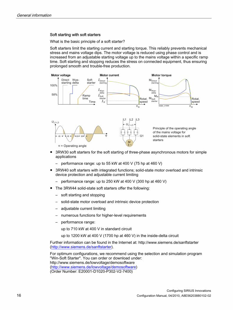
Soft starting with soft starters What is the basic principle of a soft starter? Soft starters limit the starting current and starting torque. This reliably prevents mechanical stress and mains voltage dips. The motor voltage is reduced using phase control and is increased from an adjustable starting voltage up to the mains voltage within a specific ramp time. Soft starting and stopping reduces the stress on connected equipment, thus ensuring prolonged smooth and trouble-free production.
M3 ~
100%
58%
U
tnerruc rotoMegatlov rotoM
N
Direct starting
Soft starter
Direct starting
Wye-delta
Soft starter
Ramp time
Time
Wye-delta
M
M
M
Motor torque Direct starting
Wye-delta
Soft starter
MRotat. speed
N
nNNSB0_01999
Rotat. speed
nN
UL1 L2 L3
G1
L1-L3
L1-L3
● 3RW30 soft starters for the soft starting of three-phase asynchronous motors for simple
applications – performance range: up to 55 kW at 400 V (75 hp at 460 V)
● 3RW40 soft starters with integrated functions; solid-state motor overload and intrinsic device protection and adjustable current limiting – performance range: up to 250 kW at 400 V (300 hp at 460 V)
● The 3RW44 solid-state soft starters offer the following: – soft starting and stopping – solid-state motor overload and intrinsic device protection – adjustable current limiting – numerous functions for higher-level requirements – performance range:
up to 710 kW at 400 V in standard circuit up to 1200 kW at 400 V (1700 hp at 460 V) in the inside-delta circuit
Further information can be found in the Internet at: http://www.siemens.de/sanftstarter (http://www.siemens.de/sanftstarter). For optimum configurations, we recommend using the selection and simulation program "Win-Soft Starter". You can order or download under: http://www.siemens.de/lowvoltage/demosoftware (http://www.siemens.de/lowvoltage/demosoftware) (Order Number: E20001-D1020-P302-V2-7400)

General information
Configuring SIRIUS Innovations Configuration Manual, 04/2010, A8E56203880102-02 17
Load feeders with soft starters Soft starters can also be used to prevent current peaks in the line supply instead of the star(wye)-delta starting combinations. Three versions of these soft starters are available: ● 3RW30 ● 3RW40 ● 3RW44 The 3RW4 soft starters come as standard with an integrated solid-state overload relay. This means that, in fuseless combinations, a motor starter protector is only required for short-circuit protection. In the case of 3RW30 soft starters, the motor starter protector must also cover the overload protection.
3RB22 / 23 overload relays and SIMOCODE pro The modular, solid-state overload relays with external power supply type 3RB22 / 23 for high-feature applications up to 630 A have been designed for inverse-time delayed protection of loads with normal and heavy starting against excessive temperature rises due to overload, phase unbalance or phase failure. SIMOCODE pro is a flexible, modular motor management system for motors with constant speeds in the low-voltage performance range. It provides the intelligent, communication-capable interface between the higher-level automation system and the motor feeder. A configuration with 3RB22 / 23 overload relays and with SIMOCODE pro requires in each case a basic unit, a connection cable and a current measuring module. The MLFBs of the current measuring modules are listed in the tables. Details of the basic units and connection cables are given in the following:
3RB22 / 23 ● Basic unit (= evaluation module)
– Monostable, screw: 3RB2283-4AA1 – Bistable, screw: 3RB2383-4AA1 – Monostable, spring-loaded: 3RB2283-4AC1 – Bistable, spring-loaded: 3RB2383-4AC1
● Connection cable – 0.1 m (S00-S3): 3RB2987-2B – 0.5 m (S00-S12): 3RB2987-2D
● For other accessories for 3RB22 / 23 overload relays see Catalog LV 1 Chapter 5.

General information
Configuring SIRIUS Innovations 18 Configuration Manual, 04/2010, A8E56203880102-02
SIMOCODE pro ● SIMOCODE pro C, Basic Unit 1
PROFIBUS DP interface, 12 Mbit/s, RS485 4I / 3O freely assignable, input for thermistor connection, monostable relay outputs – 24 V DC: 3UF7000-1AB00-0 – 110 ... 240 V AC / DC: 3UF7000-1AU00-0
● SIMOCODE pro V, Basic Unit 2 PROFIBUS DP interface, 12 Mbit/s, RS485 4I / 3O freely assignable, input for thermistor connection, monostable relay outputs, can be expanded by expansion modules – 24 V DC: 3UF7010-1AB00-0 – 110 ... 240 V AC / DC: 3UF7010-1AU00-0
● Connection cable – 0.1 m, flat: 3UF7931-0AA00-0 – 0.3 m, flat: 3UF7935-0AA00-0 – 0.5 m, flat: 3UF7932-0AA00-0 – 0.5 m, round: 3UF7932-0BA00-0 – 1.0 m, round: 3UF7937-0BA00-0 – 2.5 m, round: 3UF7933-0BA00-0
● For other accessories and software for SIMOCODE pro see Catalog LV 1 Chapter 7.

General information
Configuring SIRIUS Innovations Configuration Manual, 04/2010, A8E56203880102-02 19
Link modules
Table 2- 1 Link module versions
Connection system
Link module version Order number
Motor starter protector – contactor in size S00
3RA1921-1D
Motor starter protector – contactor in size S0 AC
3RA2921-1A
Motor starter protector – contactor in size S0 DC Motor starter protector – soft starter in size S00 Motor starter protector – soft starter in size S0
Screw-type connection system
Motor starter protector – solid-state contactor
3RA2921-1B

General information
Configuring SIRIUS Innovations 20 Configuration Manual, 04/2010, A8E56203880102-02
Connection system
Link module version Order number
Motor starter protector – contactor in size S00
3RA2911-2A
Motor starter protector – contactor in size S0
3RA2921-2A
Motor starter protector – soft starter in size S00
3RA2911-2G
Spring-loaded connection system
Motor starter protector – soft starter in size S0
3RA2921-2G

General information
Configuring SIRIUS Innovations Configuration Manual, 04/2010, A8E56203880102-02 21
Connection system
Link module version Order number
Motor starter protector – contactor in size S00
3RA2911-2F Hybrid connection system1)
Motor starter protector – contactor in size S0
3RA2921-2F
1) The motor starter protector has a screw connection and the contactor has a spring-loaded connection.

General information
Configuring SIRIUS Innovations 22 Configuration Manual, 04/2010, A8E56203880102-02

Configuring SIRIUS Innovations Configuration Manual, 04/2010, A8E56203880102-02 23
Selection tables 400 V AC 33.1 Motor starter protector + contactor
CLASS 10, type of coordination 1, short-circuit breaking capacity Iq = 150 kA
Standard three-phase motor 4-pole at 400 V AC1) Standard output P Motor current I
Setting range Overload release Motor starter protector
Motor starter protector Motor protection
Contactor2)
kW A A Order No. Order No.
Size
0,04 0,16 0,11 ... 0,16 3RV2011-0AA10 3RT2015-1AP01 S00/S00 0,06 0,2 0,14 ... 0,20 3RV2011-0BA10 3RT2015-1AP01 S00/S00 0,06 0,2 0,18 ... 0,25 3RV2011-0CA10 3RT2015-1AP01 S00/S00 0,09 0,3 0,22 ... 0,32 3RV2011-0DA10 3RT2015-1AP01 S00/S00 0,09 0,3 0,28 ... 0,40 3RV2011-0EA10 3RT2015-1AP01 S00/S00 0,12 0,4 0,35 ... 0,50 3RV2011-0FA10 3RT2015-1AP01 S00/S00 0,18 0,6 0,45 ... 0,63 3RV2011-0GA10 3RT2015-1AP01 S00/S00 0,18 0,6 0,55 ... 0,80 3RV2011-0HA10 3RT2015-1AP01 S00/S00 0,25 0,85 0,70 ... 1,00 3RV2011-0JA10 3RT2015-1AP01 S00/S00 0,37 1,1 0,90 ... 1,25 3RV2011-0KA10 3RT2015-1AP01 S00/S00 0,55 1,5 1,1 ... 1,6 3RV2011-1AA10 3RT2015-1AP01 S00/S00 0,75 1,9 1,4 ... 2,0 3RV2011-1BA10 3RT2015-1AP01 S00/S00 0,75 1,9 1,8 ... 2,5 3RV2011-1CA10 3RT2015-1AP01 S00/S00 1,1 2,7 2,2 ... 3,2 3RV2011-1DA10 3RT2015-1AP01 S00/S00 1,5 3,6 2,8 ... 4,0 3RV2011-1EA10 3RT2015-1AP01 S00/S00 1,5 3,6 3,5 ... 5,0 3RV2011-1FA10 3RT2015-1AP01 S00/S00 2,2 5 4,5 ... 6,3 3RV2011-1GA10 3RT2015-1AP01 S00/S00 3 6,5 5,5 ... 8,0 3RV2011-1HA10 3RT2015-1AP01 S00/S00 4 8,5 7,0 ... 10,0 3RV2011-1JA10 3RT2016-1AP01 S00/S00 5,5 11,5 9,0 ... 12,5 3RV2011-1KA10 3RT2017-1AP01 S00/S00 7,5 15,5 11 ... 16 3RV2011-4AA10 3RT2018-1AP01 S00/S00 7,5 15,5 14 ... 20 3RV2021-4BA10 3RT2025-1AP00 S0/S0 11 22 20 ... 25 3RV2021-4DA10 3RT2026-1AP00 S0/S0

Selection tables 400 V AC 3.1 Motor starter protector + contactor
Configuring SIRIUS Innovations 24 Configuration Manual, 04/2010, A8E56203880102-02
Standard three-phase motor 4-pole at 400 V AC1) Standard output P Motor current I
Setting range Overload release Motor starter protector
Motor starter protector Motor protection
Contactor2)
kW A A Order No. Order No.
Size
15 29 27 ... 32 3RV2021-4EA10 3RT2027-1AP00 S0/S0 Short-circuit breaking capacity Iq = 55 kA 18,5 3) 35 30 ... 36 3RV2021-4PA10 3RT2028-1AP00 S0/S0 18,5 3) 35 34 ... 40 3RV2021-4FA10 3RT2028-1AP00 S0/S0
Order numbers for basic versions with screw terminals and spring-loaded terminals also possible. 1) Guide value for 4-pole standard motors at 400 V AC, 50 Hz. Selection depends on the concrete startup and rated data
of the protected motor. 2) Rated control supply voltage 230 V AC, 50 Hz, other control voltages possible. 3) Discrete mounting only, without a link module.

Selection tables 400 V AC 3.1 Motor starter protector + contactor
Configuring SIRIUS Innovations Configuration Manual, 04/2010, A8E56203880102-02 25
CLASS 10, type of coordination 2, short-circuit breaking capacity Iq = 150 kA
Standard three-phase motor 4-pole at 400 V AC1) Standard output P Motor current
(guide value) I
Setting range Overload release Motor starter protector
Motor starter protector Motor protection
Contactor2)
kW A A Order No. Order No.
Size
0,04 0,16 0,11 ... 0,16 3RV2011-0AA10 3RT2015-1AP01 S00/S00 0,06 0,2 0,14 ... 0,20 3RV2011-0BA10 3RT2015-1AP01 S00/S00 0,06 0,2 0,18 ... 0,25 3RV2011-0CA10 3RT2015-1AP01 S00/S00 0,09 0,3 0,22 ... 0,32 3RV2011-0DA10 3RT2015-1AP01 S00/S00 0,09 0,3 0,28 ... 0,40 3RV2011-0EA10 3RT2015-1AP01 S00/S00 0,12 0,4 0,35 ... 0,50 3RV2011-0FA10 3RT2015-1AP01 S00/S00 0,18 0,6 0,45 ... 0,63 3RV2011-0GA10 3RT2015-1AP01 S00/S00 0,18 0,6 0,55 ... 0,80 3RV2011-0HA10 3RT2015-1AP01 S00/S00 0,25 0,85 0,70 ... 1,00 3RV2011-0JA10 3RT2015-1AP01 S00/S00 0,37 1,1 0,90 ... 1,25 3RV2011-0KA10 3RT2015-1AP01 S00/S00 0,55 1,5 1,1 ... 1,6 3RV2011-1AA10 3RT2015-1AP01 S00/S00 0,75 1,9 1,4 ... 2,0 3RV2011-1BA10 3RT2015-1AP01 S00/S00 0,75 1,9 1,8 ... 2,5 3RV2011-1CA10 3RT2015-1AP01 S00/S00 1,1 2,7 2,2 ... 3,2 3RV2011-1DA10 3RT2015-1AP01 S00/S00 1,5 3,6 2,8 ... 4,0 3RV2011-1EA10 3RT2015-1AP01 S00/S00 1,5 3,6 3,5 ... 5,0 3RV2011-1FA10 3RT2024-1AP00 S00/S0 2,2 5 4,5 ... 6,3 3RV2011-1GA10 3RT2024-1AP00 S00/S0 3 6,5 5,5 ... 8,0 3RV2011-1HA10 3RT2024-1AP00 S00/S0 4 8,5 7,0 ... 10,0 3RV2011-1JA10 3RT2024-1AP00 S00/S0 5,5 11,5 9,0 ... 12,5 3RV2011-1KA10 3RT2024-1AP00 S00/S0 7,5 15,5 11 ... 16 3RV2011-4AA10 3RT2026-1AP00 S00/S0 7,5 15,5 14 ... 20 3RV2021-4BA10 3RT2027-1AP00 S0/S0 11 22 20 ... 25 3RV2021-4DA10 3RT2027-1AP00 S0/S0 15 29 27 ... 32 3RV2021-4EA10 3RT2027-1AP00 S0/S0

Selection tables 400 V AC 3.1 Motor starter protector + contactor
Configuring SIRIUS Innovations 26 Configuration Manual, 04/2010, A8E56203880102-02
Standard three-phase motor 4-pole at 400 V AC1) Standard output P Motor current
(guide value) I
Setting range Overload release Motor starter protector
Motor starter protector Motor protection
Contactor2)
kW A A Order No. Order No.
Size
Short-circuit breaking capacity Iq = 55 kA 18,5 3) 35 30 ... 36 3RV2021-4PA10 3RT1035-1AP00 S0/S2 18,5 3) 35 34 ... 40 3RV2021-4FA10 3RT1035-1AP00 S0/S2
Order numbers for basic versions with screw terminals and spring-loaded terminals also possible. 1) Guide value for 4-pole standard motors at 400 V AC, 50 Hz. Selection depends on the concrete startup and rated data
of the protected motor. 2) Rated control supply voltage 230 V AC, 50 Hz, other control voltages possible. 3) Discrete mounting only, without a link module.

Selection tables 400 V AC 3.2 Circuit breaker + contactor + thermal overload relay
Configuring SIRIUS Innovations Configuration Manual, 04/2010, A8E56203880102-02 27
3.2 Circuit breaker + contactor + thermal overload relay
CLASS 10, type of coordination 1, short-circuit breaking capacity Iq = 150 kA
Standard three-phase motor 4-pole at 400 V AC1) Standard output P
Motor current I
Motor starter protector Starter protection
Contactor2) Thermal overload relay
Setting range Overload release Overload relay
kW A Order No. Order No.
Size
Order No. A 0,06 0,2 3RV2311-0BC10 3RT2015-1AP01 S00/S00/S00 3RU2116-0BB0 0,14 ... 0,20 0,06 0,2 3RV2311-0CC10 3RT2015-1AP01 S00/S00/S00 3RU2116-0CB0 0,18 ... 0,25 0,09 0,3 3RV2311-0DC10 3RT2015-1AP01 S00/S00/S00 3RU2116-0DB0 0,22 ... 0,32 0,09 0,3 3RV2311-0EC10 3RT2015-1AP01 S00/S00/S00 3RU2116-0EB0 0,28 ... 0,40 0,12 0,4 3RV2311-0FC10 3RT2015-1AP01 S00/S00/S00 3RU2116-0FB0 0,35 ... 0,50 0,18 0,6 3RV2311-0GC10 3RT2015-1AP01 S00/S00/S00 3RU2116-0GB0 0,45 ... 0,63 0,18 0,6 3RV2311-0HC10 3RT2015-1AP01 S00/S00/S00 3RU2116-0HB0 0,55 ... 0,80 0,25 0,85 3RV2311-0JC10 3RT2015-1AP01 S00/S00/S00 3RU2116-0JB0 0,70 ... 1,00 0,37 1,1 3RV2311-0KC10 3RT2015-1AP01 S00/S00/S00 3RU2116-0KB0 0,90 ... 1,25 0,55 1,5 3RV2311-1AC10 3RT2015-1AP01 S00/S00/S00 3RU2116-1AB0 1,1 ... 1,6 0,75 1,9 3RV2311-1BC10 3RT2015-1AP01 S00/S00/S00 3RU2116-1BB0 1,4 ... 2,0 0,75 1,9 3RV2311-1CC10 3RT2015-1AP01 S00/S00/S00 3RU2116-1CB0 1,8 ... 2,5 1,1 2,7 3RV2311-1DC10 3RT2015-1AP01 S00/S00/S00 3RU2116-1DB0 2,2 ... 3,2 1,5 3,6 3RV2311-1EC10 3RT2015-1AP01 S00/S00/S00 3RU2116-1EB0 2,8 ... 4,0 1,5 3,6 3RV2311-1FC10 3RT2015-1AP01 S00/S00/S00 3RU2116-1FB0 3,5 ... 5,0 2,2 5 3RV2311-1GC10 3RT2015-1AP01 S00/S00/S00 3RU2116-1GB0 4,5 ... 6,3 3 6,5 3RV2311-1HC10 3RT2015-1AP01 S00/S00/S00 3RU2116-1HB0 5,5 ... 8,0 4 8,5 3RV2311-1JC10 3RT2016-1AP01 S00/S00/S00 3RU2116-1JB0 7,0 ... 10,0 5,5 11,5 3RV2311-1KC10 3RT2017-1AP01 S00/S00/S00 3RU2116-1KB0 9,0 ... 12,5 7,5 15,5 3RV2311-4AC10 3RT2018-1AP01 S00/S00/S00 3RU2116-4AB0 11 ... 16 7,5 15,5 3RV2321-4AC10 3RT2025-1AP00 S0/S0/S0 3RU2126-4AB0 11 ... 16 7,5 15,5 3RV2321-4BC10 3RT2025-1AP00 S0/S0/S0 3RU2126-4BB0 14 ... 20 11 22 3RV2321-4DC10 3RT2026-1AP00 S0/S0/S0 3RU2126-4DB0 20 ... 25 15 29 3RV2321-4EC10 3RT2027-1AP00 S0/S0/S0 3RU2126-4EB0 27 ... 32

Selection tables 400 V AC 3.2 Circuit breaker + contactor + thermal overload relay
Configuring SIRIUS Innovations 28 Configuration Manual, 04/2010, A8E56203880102-02
Standard three-phase motor 4-pole at 400 V AC1) Standard output P
Motor current I
Motor starter protector Starter protection
Contactor2) Thermal overload relay
Setting range Overload release Overload relay
kW A Order No. Order No.
Size
Order No. A Short-circuit breaking capacity Iq = 55 kA 18,5 3) 35 3RV2321-4PC10 3RT2028-1AP00 S0/S0/S0 3RU2126-4PB0 30 ... 36 18,5 3) 35 3RV2321-4FC10 3RT2028-1AP00 S0/S0/S0 3RU2126-4FB0 34 ... 40
Order numbers for basic versions with screw terminals and spring-loaded terminals also possible. 1) Guide value for 4-pole standard motors at 400 V AC, 50 Hz. Selection depends on the concrete startup and rated data
of the protected motor. 2) Rated control supply voltage 230 V AC, 50 Hz, other control voltages possible. 3) Discrete mounting only, without a link module.

Selection tables 400 V AC 3.2 Circuit breaker + contactor + thermal overload relay
Configuring SIRIUS Innovations Configuration Manual, 04/2010, A8E56203880102-02 29
CLASS 10, type of coordination 2, short-circuit breaking capacity Iq = 150 kA
Standard three-phase motor 4-pole at 400 V AC1) Standard output P
Motor current I
Motor starter protector Starter protection
Contactor2) Thermal overload relay
Setting range Overload release Overload relay
kW A Order No. Order No.
Size
Order No. A 0,06 0,2 3RV2311-0BC10 3RT2015-1AP01 S00/S00/S00 3RU2116-0BB0 0,14 ... 0,20 0,06 0,2 3RV2311-0CC10 3RT2015-1AP01 S00/S00/S00 3RU2116-0CB0 0,18 ... 0,25 0,09 0,3 3RV2311-0DC10 3RT2015-1AP01 S00/S00/S00 3RU2116-0DB0 0,22 ... 0,32 0,09 0,3 3RV2311-0EC10 3RT2015-1AP01 S00/S00/S00 3RU2116-0EB0 0,28 ... 0,40 0,12 0,4 3RV2311-0FC10 3RT2015-1AP01 S00/S00/S00 3RU2116-0FB0 0,35 ... 0,50 0,18 0,6 3RV2311-0GC10 3RT2015-1AP01 S00/S00/S00 3RU2116-0GB0 0,45 ... 0,63 0,18 0,6 3RV2311-0HC10 3RT2015-1AP01 S00/S00/S00 3RU2116-0HB0 0,55 ... 0,80 0,25 0,85 3RV2311-0JC10 3RT2015-1AP01 S00/S00/S00 3RU2116-0JB0 0,70 ... 1,00 0,37 1,1 3RV2311-0KC10 3RT2015-1AP01 S00/S00/S00 3RU2116-0KB0 0,90 ... 1,25 0,55 1,5 3RV2311-1AC10 3RT2015-1AP01 S00/S00/S00 3RU2116-1AB0 1,1 ... 1,6 0,75 1,9 3RV2311-1BC10 3RT2015-1AP01 S00/S00/S00 3RU2116-1BB0 1,4 ... 2,0 0,75 1,9 3RV2311-1CC10 3RT2015-1AP01 S00/S00/S00 3RU2116-1CB0 1,8 ... 2,5 1,1 2,7 3RV2311-1DC10 3RT2015-1AP01 S00/S00/S00 3RU2116-1DB0 2,2 ... 3,2 1,5 3,6 3RV2311-1EC10 3RT2015-1AP01 S00/S00/S00 3RU2116-1EB0 2,8 ... 4,0 1,5 3,6 3RV2311-1FC10 3RT2024-1AP00 S00/S0/S00 3RU2116-1FB0 3,5 ... 5,0 2,2 5 3RV2311-1GC10 3RT2024-1AP00 S00/S0/S0 3RU2126-1GB03) 4,5 ... 6,3 3 6,5 3RV2311-1HC10 3RT2024-1AP00 S00/S0/S0 3RU2126-1HB03) 5,5 ... 8,0 4 8,5 3RV2311-1JC10 3RT2024-1AP00 S00/S0/S0 3RU2126-1JB03) 7,0 ... 10,0 5,5 11,5 3RV2311-1KC10 3RT2024-1AP00 S00/S0/S0 3RU2126-1KB03) 9,0 ... 12,5 7,5 15,5 3RV2311-4AC10 3RT2026-1AP00 S00/S0/S0 3RU2126-4AB03) 11 ... 16 7,5 15,5 3RV2321-4BC10 3RT2027-1AP00 S0/S0/S0 3RU2126-4BB0 14 ... 20 11 22 3RV2321-4DC10 3RT2027-1AP00 S0/S0/S0 3RU2126-4DB0 20 ... 25 15 29 3RV2321-4EC10 3RT2027-1AP00 S0/S0/S0 3RU2126-4EB0 27 ... 32

Selection tables 400 V AC 3.2 Circuit breaker + contactor + thermal overload relay
Configuring SIRIUS Innovations 30 Configuration Manual, 04/2010, A8E56203880102-02
Standard three-phase motor 4-pole at 400 V AC1) Standard output P
Motor current I
Motor starter protector Starter protection
Contactor2) Thermal overload relay
Setting range Overload release Overload relay
kW A Order No. Order No.
Size
Order No. A Short-circuit breaking capacity Iq = 55 kA 18,5 35 3RV2321-4PC10 3RT1035-1AP00 S0/S2/S0 3RU2126-4PB0 30 ... 36 18,5 35 3RV2321-4PC10 3RT1035-1AP00 S0/S2/S2 3RU1136-4FB0 28 ... 40 18,5 4) 35 3RV2321-4FC10 3RT1035-1AP00 S0/S2/S0 3RU2126-4FB0 34 ... 40 18,5 4) 35 3RV2321-4FC10 3RT1035-1AP00 S0/S2/S2 3RU1136-4FB0 28 ... 40
Order numbers for basic versions with screw terminals and spring-loaded terminals also possible. 1) Guide value for 4-pole standard motors at 400 V AC, 50 Hz. Selection depends on the concrete startup and rated data
of the protected motor. 2) Rated control supply voltage 230 V AC, 50 Hz, other control voltages possible. 3) Can also be used in size S00 (3RU2116). 4) Discrete mounting only, without a link module.

Selection tables 400 V AC 3.3 Circuit breaker + contactor + 3RB3 solid-state overload relay
Configuring SIRIUS Innovations Configuration Manual, 04/2010, A8E56203880102-02 31
3.3 Circuit breaker + contactor + 3RB3 solid-state overload relay
Type of coordination 1, short-circuit breaking capacity Iq = 150 kA
Standard three-phase motor 4-pole at 400 V AC1) Stan-dard output P
Motor current I
Setting range Overload release Motor starter protector
Motor starter protector Starter protection
Contactor2) Overload relay (solid-state)
Setting rangeOverload release Overload relay
kW A Order No. Order No. Order No.
Size
Order No. A CLASS 10 0,06 0,2 None 3RV2311-0CC10 3RT2015-1AP01 S00/S00/S00 3RB3016-1RB0 0,1 ... 0,4 0,09 0,3 None 3RV2311-0DC10 3RT2015-1AP01 S00/S00/S00 3RB3016-1RB0 0,1 ... 0,4 0,12 0,4 None 3RV2311-0HC10 3RT2015-1AP01 S00/S00/S00 3RB3016-1NB0 0,32 ... 1,25 0,18 0,6 None 3RV2311-0JC10 3RT2015-1AP01 S00/S00/S00 3RB3016-1NB0 0,32 ... 1,25 0,25 0,85 None 3RV2311-0KC10 3RT2015-1AP01 S00/S00/S00 3RB3016-1NB0 0,32 ... 1,25 0,37 1,1 None 3RV2311-1AC10 3RT2015-1AP01 S00/S00/S00 3RB3016-1PB0 1 ... 4 0,55 1,5 None 3RV2311-1BC10 3RT2015-1AP01 S00/S00/S00 3RB3016-1PB0 1 ... 4 0,75 1,9 None 3RV2311-1BC10 3RT2015-1AP01 S00/S00/S00 3RB3016-1PB0 1 ... 4 1,1 2,7 None 3RV2311-1DC10 3RT2015-1AP01 S00/S00/S00 3RB3016-1PB0 1 ... 4 1,5 3,5 None 3RV2311-1EC10 3RT2015-1AP01 S00/S00/S00 3RB3016-1SB0 3 ... 12 2,2 5 None 3RV2311-1GC10 3RT2015-1AP01 S00/S00/S00 3RB3016-1SB0 3 ... 12 3 6,5 None 3RV2311-1HC10 3RT2015-1AP01 S00/S00/S00 3RB3016-1SB0 3 ... 12 4 8,5 None 3RV2311-1JC10 3RT2016-1AP01 S00/S00/S00 3RB3016-1TB0 4 ... 16 5,5 11,5 None 3RV2311-4AC10 3RT2024-1AP00 S00/S0/S0 3RB3026-1QB0 6 ... 25 7,5 15,5 None 3RV2321-4BC10 3RT2025-1AP00 S0/S0/S0 3RB3026-1QB0 6 ... 25 11 22 None 3RV2321-4EC10 3RT2027-1AP00 S0/S0/S0 3RB3026-1VE0 10 ... 40
Order numbers for basic versions with screw terminals and spring-loaded terminals also possible. 3RA2921-1BA00 link module can only be used with screw terminals.
1) Guide value for 4-pole standard motors at 400 V AC, 50 Hz. Selection depends on the concrete startup and rated data of the protected motor.
2) Rated control supply voltage 230 V AC, 50 Hz, other control voltages possible.

Selection tables 400 V AC 3.3 Circuit breaker + contactor + 3RB3 solid-state overload relay
Configuring SIRIUS Innovations 32 Configuration Manual, 04/2010, A8E56203880102-02
Type of coordination 2, short-circuit breaking capacity Iq = 150 kA
Standard three-phase motor 4-pole at 400 V AC1) Stan-dard output P
Motor current I
Setting range Overload release Motor starter protector
Motor starter protector Starter protection3)
Contactor2) Overload relay (solid-state)
Setting rangeOverload release Overload relay
kW A Order No. Order No. Order No.
Size
Order No. A CLASS 10 0,06 0,2 None 3RV2311-0CC10 3RT2015-1AP01 S00/S00/S00 3RB3016-1RB0 0,1 ... 0,4 0,09 0,3 None 3RV2311-0DC10 3RT2015-1AP01 S00/S00/S00 3RB3016-1RB0 0,1 ... 0,4 0,12 0,4 None 3RV2311-0HC10 3RT2015-1AP01 S00/S00/S00 3RB3016-1NB0 0,32 ... 1,25 0,18 0,6 None 3RV2311-0JC10 3RT2015-1AP01 S00/S00/S00 3RB3016-1NB0 0,32 ... 1,25 0,25 0,85 None 3RV2311-0KC10 3RT2015-1AP01 S00/S00/S00 3RB3016-1NB0 0,32 ... 1,25 0,37 1,1 None 3RV2311-1AC10 3RT2015-1AP01 S00/S00/S00 3RB3016-1PB0 1 ... 4 0,55 1,5 None 3RV2311-1BC10 3RT2015-1AP01 S00/S00/S00 3RB3016-1PB0 1 ... 4 0,75 1,9 None 3RV2311-1BC10 3RT2015-1AP01 S00/S00/S00 3RB3016-1PB0 1 ... 4 1,1 2,7 None 3RV2311-1DC10 3RT2015-1AP01 S00/S00/S00 3RB3016-1PB0 1 ... 4 1,5 3,5 None 3RV2311-1EC10 3RT2015-1AP01 S00/S00/S00 3RB3016-1SB0 3 ... 12 2,2 5 None 3RV2311-1GC10 3RT2024-1AP00 S00/S0/S0 3RB3026-1SB0 3 ... 12 3 6,5 None 3RV2311-1HC10 3RT2024-1AP00 S00/S0/S0 3RB3026-1SB0 3 ... 12 4 8,5 None 3RV2311-1JC10 3RT2024-1AP00 S00/S0/S0 3RB3026-1QB0 6 ... 25 5,5 11,5 None 3RV2311-4AC10 3RT2026-1AP00 S00/S0/S0 3RB3026-1QB0 6 ... 25 7,5 15,5 None 3RV2321-4BC10 3RT2027-1AP00 S0/S0/S0 3RB3026-1QB0 6 ... 25 11 22 None 3RV2321-4EC10 3RT2027-1AP00 S0/S0/S0 3RB3026-1VB0 10 ... 40 CLASS 20 0,06 0,2 0,35 ... 0,5 3RV2011-0FA10 3RT2015-1AP01 S00/S00/S00 3RB3016-2RB0 0,1 ... 0,4 0,09 0,3 0,55 ... 0,8 3RV2011-0HA10 3RT2015-1AP01 S00/S00/S00 3RB3016-2RB0 0,1 ... 0,4 0,12 0,4 0,7 ... 1 3RV2011-0JA10 3RT2015-1AP01 S00/S00/S00 3RB3016-2NB0 0,32 ... 1,25 0,18 0,6 1,1 ... 1,6 3RV2011-1AA10 3RT2015-1AP01 S00/S00/S00 3RB3016-2NB0 0,32 ... 1,25 0,25 0,85 1,4 ... 2 3RV2011-1BA10 3RT2015-1AP01 S00/S00/S00 3RB3016-2NB0 0,32 ... 1,25 0,37 1,1 1,8 ... 2,5 3RV2011-1CA10 3RT2015-1AP01 S00/S00/S00 3RB3016-2PB0 1 ... 4 0,55 1,5 2,2 ... 3,2 3RV2011-1DA10 3RT2015-1AP01 S00/S00/S00 3RB3016-2PB0 1 ... 4 0,75 1,9 3,5 ... 5 3RV2011-1FA10 3RT2024-1AP00 S00/S0/S0 3RB3026-2PB0 1 ... 4 1,1 2,7 4,5 ... 6,3 3RV2011-1GA10 3RT2024-1AP00 S00/S0/S0 3RB3026-2PB0 1 ... 4

Selection tables 400 V AC 3.3 Circuit breaker + contactor + 3RB3 solid-state overload relay
Configuring SIRIUS Innovations Configuration Manual, 04/2010, A8E56203880102-02 33
Standard three-phase motor 4-pole at 400 V AC1) Stan-dard output P
Motor current I
Setting range Overload release Motor starter protector
Motor starter protector Starter protection3)
Contactor2) Overload relay (solid-state)
Setting rangeOverload release Overload relay
kW A Order No. Order No. Order No.
Size
Order No. A 1,5 3,5 5,5 ... 8 3RV2011-1HA10 3RT2024-1AP00 S00/S0/S0 3RB3026-2PB0 1 ... 4 2,2 5 7 ... 10 3RV2011-1JA10 3RT2024-1AP00 S00/S0/S0 3RB3026-2SB0 3 ... 12 3 6,5 11 ... 16 3RV2021-4AA10 3RT2026-1AP00 S0/S0/S0 3RB3026-2QB0 6 ... 25 4 8,5 14 ... 20 3RV2021-4BA10 3RT2027-1AP00 S0/S0/S0 3RB3026-2QB0 6 ... 25 5,5 11,5 20 ... 25 3RV2021-4DA10 3RT2027-1AP00 S0/S0/S0 3RB3026-2QB0 6 ... 25 CLASS 30 0,06 0,2 0,55 ... 0,8 3RV2011-0HA10 3RT2015-1AP01 S00/S00/S00 3RB3113-4RB0 0,1 ... 0,4 0,09 0,3 0,7 ... 1 3RV2011-0JA10 3RT2015-1AP01 S00/S00/S00 3RB3113-4RB0 0,1 ... 0,4 0,12 0,4 1,1 ... 1,6 3RV2011-1AA10 3RT2015-1AP01 S00/S00/S00 3RB3113-4NB0 0,32 ... 1,25 0,18 0,6 1,4 ... 2 3RV2011-1BA10 3RT2015-1AP01 S00/S00/S00 3RB3113-4NB0 0,32 ... 1,25 0,25 0,85 1,8 ... 2,5 3RV2011-1CA10 3RT2015-1AP01 S00/S00/S00 3RB3113-4NB0 0,32 ... 1,25 0,37 1,1 2,2 ... 3,2 3RV2011-1DA10 3RT2015-1AP01 S00/S00/S00 3RB3113-4PB0 1 ... 4 0,55 1,5 3,5 ... 5 3RV2011-1FA10 3RT2024-1AP00 S00/S0/S0 3RB3123-4PB0 1 ... 4 0,75 1,9 4,5 ... 6,3 3RV2011-1GA10 3RT2024-1AP00 S00/S0/S0 3RB3123-4PB0 1 ... 4 1,1 2,7 5,5 ... 8 3RV2011-1HA10 3RT2024-1AP00 S00/S0/S0 3RB3123-4PB0 1 ... 4 1,5 3,5 7 ... 10 3RV2011-1JA10 3RT2024-1AP00 S00/S0/S0 3RB3123-4SB0 3 ... 12 2,2 5 11 ... 16 3RV2021-4AA10 3RT2026-1AP00 S0/S0/S0 3RB3123-4SB0 3 ... 12 3 6,5 14 ... 20 3RV2021-4BA10 3RT2027-1AP00 S0/S0/S0 3RB3123-4QB0 6 ... 25 4 8,5 20 ... 25 3RV2021-4DA10 3RT2027-1AP00 S0/S0/S0 3RB3123-4QB0 6 ... 25 5,5 11,5 27 ... 32 3RV2021-4EA10 3RT2027-1AP00 S0/S0/S0 3RB3123-4QB0 6 ... 25
Order numbers for basic versions with screw terminals and spring-loaded terminals also possible. 3RA2921-1BA00 link module can only be used with screw terminals.
1) Guide value for 4-pole standard motors at 400 V AC, 50 Hz. Selection depends on the concrete startup and rated data of the protected motor.
2) Rated control supply voltage 230 V AC, 50 Hz, other control voltages possible. 3) The motor starter protector is to be set to maximum current value.

Selection tables 400 V AC 3.4 Circuit breaker + contactor + 3RB22 or 3RB23 solid-state overload relay, and 3UF7
Configuring SIRIUS Innovations 34 Configuration Manual, 04/2010, A8E56203880102-02
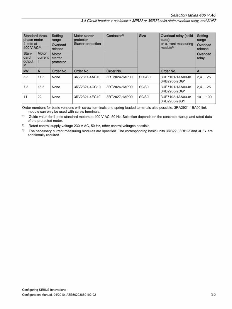
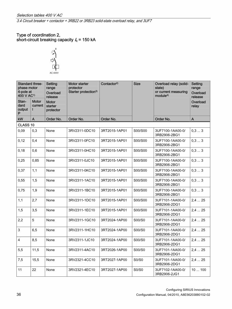
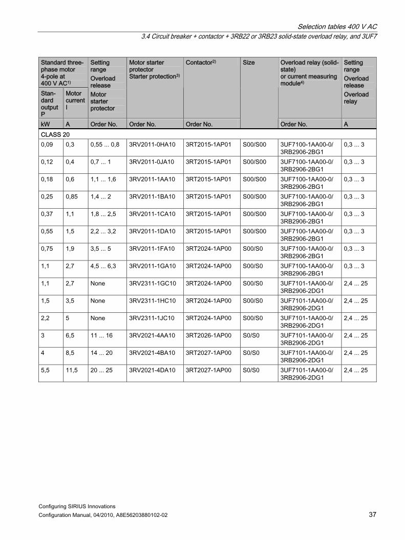
3.4 Circuit breaker + contactor + 3RB22 or 3RB23 solid-state overload relay, and 3UF7
Type of coordination 1, short-circuit breaking capacity Iq = 150 kA
Standard three-phase motor 4-pole at 400 V AC1) Stan-dard output P
Motor current I
Setting range Overload release Motor starter protector
Motor starter protector Starter protection
Contactor2) Overload relay (solid-state) or current measuring module3)
Setting range Overload release Overload relay
kW A Order No. Order No. Order No.
Size
Order No. A CLASS 10 0,09 0,3 None 3RV2311-0DC10 3RT2015-1AP01 S00/S00 3UF7100-1AA00-0/
3RB2906-2BG1 0,3 ... 3
0,12 0,4 None 3RV2311-0FC10 3RT2015-1AP01 S00/S00 3UF7100-1AA00-0/ 3RB2906-2BG1
0,3 ... 3
0,18 0,6 None 3RV2311-0HC10 3RT2015-1AP01 S00/S00 3UF7100-1AA00-0/ 3RB2906-2BG1
0,3 ... 3
0,25 0,85 None 3RV2311-0JC10 3RT2015-1AP01 S00/S00 3UF7100-1AA00-0/ 3RB2906-2BG1
0,3 ... 3
0,37 1,1 None 3RV2311-0KC10 3RT2015-1AP01 S00/S00 3UF7100-1AA00-0/ 3RB2906-2BG1
0,3 ... 3
0,55 1,5 None 3RV2311-1AC10 3RT2015-1AP01 S00/S00 3UF7100-1AA00-0/ 3RB2906-2BG1
0,3 ... 3
0,75 1,9 None 3RV2311-1BC10 3RT2015-1AP01 S00/S00 3UF7100-1AA00-0/ 3RB2906-2BG1
0,3 ... 3
1,1 2,7 None 3RV2311-1DC10 3RT2015-1AP01 S00/S00 3UF7101-1AA00-0/ 3RB2906-2DG1
2,4 ... 25
1,5 3,5 None 3RV2311-1EC10 3RT2015-1AP01 S00/S00 3UF7101-1AA00-0/ 3RB2906-2DG1
2,4 ... 25
2,2 5 None 3RV2311-1GC10 3RT2015-1AP01 S00/S00 3UF7101-1AA00-0/ 3RB2906-2DG1
2,4 ... 25
3 6,5 None 3RV2311-1HC10 3RT2015-1AP01 S00/S00 3UF7101-1AA00-0/ 3RB2906-2DG1
2,4 ... 25
4 8,5 None 3RV2311-1JC10 3RT2016-1AP01 S00/S00 3UF7101-1AA00-0/ 3RB2906-2DG1
2,4 ... 25
Selection tables 400 V AC 3.4 Circuit breaker + contactor + 3RB22 or 3RB23 solid-state overload relay, and 3UF7
Configuring SIRIUS Innovations Configuration Manual, 04/2010, A8E56203880102-02 35
Standard three-phase motor 4-pole at 400 V AC1) Stan-dard output P
Motor current I
Setting range Overload release Motor starter protector
Motor starter protector Starter protection
Contactor2) Overload relay (solid-state) or current measuring module3)
Setting range Overload release Overload relay
kW A Order No. Order No. Order No.
Size
Order No. A 5,5 11,5 None 3RV2311-4AC10 3RT2024-1AP00 S00/S0 3UF7101-1AA00-0/
3RB2906-2DG1 2,4 ... 25
7,5 15,5 None 3RV2321-4CC10 3RT2026-1AP00 S0/S0 3UF7101-1AA00-0/ 3RB2906-2DG1
2,4 ... 25
11 22 None 3RV2321-4EC10 3RT2027-1AP00 S0/S0 3UF7102-1AA00-0/ 3RB2906-2JG1
10 ... 100
Order numbers for basic versions with screw terminals and spring-loaded terminals also possible. 3RA2921-1BA00 link module can only be used with screw terminals.
1) Guide value for 4-pole standard motors at 400 V AC, 50 Hz. Selection depends on the concrete startup and rated data of the protected motor.
2) Rated control supply voltage 230 V AC, 50 Hz, other control voltages possible. 3) The necessary current measuring modules are specified. The corresponding basic units 3RB22 / 3RB23 and 3UF7 are
additionally required.
Selection tables 400 V AC 3.4 Circuit breaker + contactor + 3RB22 or 3RB23 solid-state overload relay, and 3UF7
Configuring SIRIUS Innovations 36 Configuration Manual, 04/2010, A8E56203880102-02
Type of coordination 2, short-circuit breaking capacity Iq = 150 kA
Standard three-phase motor 4-pole at 400 V AC1) Stan-dard output P
Motor current I
Setting range Overload release Motor starter protector
Motor starter protector Starter protection3)
Contactor2) Overload relay (solid-state) or current measuring module4)
Setting range Overload release Overload relay
kW A Order No. Order No. Order No.
Size
Order No. A CLASS 10 0,09 0,3 None 3RV2311-0DC10 3RT2015-1AP01 S00/S00 3UF7100-1AA00-0/
3RB2906-2BG1 0,3 ... 3
0,12 0,4 None 3RV2311-0FC10 3RT2015-1AP01 S00/S00 3UF7100-1AA00-0/ 3RB2906-2BG1
0,3 ... 3
0,18 0,6 None 3RV2311-0HC10 3RT2015-1AP01 S00/S00 3UF7100-1AA00-0/ 3RB2906-2BG1
0,3 ... 3
0,25 0,85 None 3RV2311-0JC10 3RT2015-1AP01 S00/S00 3UF7100-1AA00-0/ 3RB2906-2BG1
0,3 ... 3
0,37 1,1 None 3RV2311-0KC10 3RT2015-1AP01 S00/S00 3UF7100-1AA00-0/ 3RB2906-2BG1
0,3 ... 3
0,55 1,5 None 3RV2311-1AC10 3RT2015-1AP01 S00/S00 3UF7100-1AA00-0/ 3RB2906-2BG1
0,3 ... 3
0,75 1,9 None 3RV2311-1BC10 3RT2015-1AP01 S00/S00 3UF7100-1AA00-0/ 3RB2906-2BG1
0,3 ... 3
1,1 2,7 None 3RV2311-1DC10 3RT2015-1AP01 S00/S00 3UF7101-1AA00-0/ 3RB2906-2DG1
2,4 ... 25
1,5 3,5 None 3RV2311-1EC10 3RT2015-1AP01 S00/S00 3UF7101-1AA00-0/ 3RB2906-2DG1
2,4 ... 25
2,2 5 None 3RV2311-1GC10 3RT2024-1AP00 S00/S0 3UF7101-1AA00-0/ 3RB2906-2DG1
2,4 ... 25
3 6,5 None 3RV2311-1HC10 3RT2024-1AP00 S00/S0 3UF7101-1AA00-0/ 3RB2906-2DG1
2,4 ... 25
4 8,5 None 3RV2311-1JC10 3RT2024-1AP00 S00/S0 3UF7101-1AA00-0/ 3RB2906-2DG1
2,4 ... 25
5,5 11,5 None 3RV2311-4AC10 3RT2026-1AP00 S00/S0 3UF7101-1AA00-0/ 3RB2906-2DG1
2,4 ... 25
7,5 15,5 None 3RV2321-4CC10 3RT2027-1AP00 S0/S0 3UF7101-1AA00-0/ 3RB2906-2DG1
2,4 ... 25
11 22 None 3RV2321-4EC10 3RT2027-1AP00 S0/S0 3UF7102-1AA00-0/ 3RB2906-2JG1
10 ... 100
Selection tables 400 V AC 3.4 Circuit breaker + contactor + 3RB22 or 3RB23 solid-state overload relay, and 3UF7
Configuring SIRIUS Innovations Configuration Manual, 04/2010, A8E56203880102-02 37
Standard three-phase motor 4-pole at 400 V AC1) Stan-dard output P
Motor current I
Setting range Overload release Motor starter protector
Motor starter protector Starter protection3)
Contactor2) Overload relay (solid-state) or current measuring module4)
Setting range Overload release Overload relay
kW A Order No. Order No. Order No.
Size
Order No. A CLASS 20 0,09 0,3 0,55 ... 0,8 3RV2011-0HA10 3RT2015-1AP01 S00/S00 3UF7100-1AA00-0/
3RB2906-2BG1 0,3 ... 3
0,12 0,4 0,7 ... 1 3RV2011-0JA10 3RT2015-1AP01 S00/S00 3UF7100-1AA00-0/ 3RB2906-2BG1
0,3 ... 3
0,18 0,6 1,1 ... 1,6 3RV2011-1AA10 3RT2015-1AP01 S00/S00 3UF7100-1AA00-0/ 3RB2906-2BG1
0,3 ... 3
0,25 0,85 1,4 ... 2 3RV2011-1BA10 3RT2015-1AP01 S00/S00 3UF7100-1AA00-0/ 3RB2906-2BG1
0,3 ... 3
0,37 1,1 1,8 ... 2,5 3RV2011-1CA10 3RT2015-1AP01 S00/S00 3UF7100-1AA00-0/ 3RB2906-2BG1
0,3 ... 3
0,55 1,5 2,2 ... 3,2 3RV2011-1DA10 3RT2015-1AP01 S00/S00 3UF7100-1AA00-0/ 3RB2906-2BG1
0,3 ... 3
0,75 1,9 3,5 ... 5 3RV2011-1FA10 3RT2024-1AP00 S00/S0 3UF7100-1AA00-0/ 3RB2906-2BG1
0,3 ... 3
1,1 2,7 4,5 ... 6,3 3RV2011-1GA10 3RT2024-1AP00 S00/S0 3UF7100-1AA00-0/ 3RB2906-2BG1
0,3 ... 3
1,1 2,7 None 3RV2311-1GC10 3RT2024-1AP00 S00/S0 3UF7101-1AA00-0/ 3RB2906-2DG1
2,4 ... 25
1,5 3,5 None 3RV2311-1HC10 3RT2024-1AP00 S00/S0 3UF7101-1AA00-0/ 3RB2906-2DG1
2,4 ... 25
2,2 5 None 3RV2311-1JC10 3RT2024-1AP00 S00/S0 3UF7101-1AA00-0/ 3RB2906-2DG1
2,4 ... 25
3 6,5 11 ... 16 3RV2021-4AA10 3RT2026-1AP00 S0/S0 3UF7101-1AA00-0/ 3RB2906-2DG1
2,4 ... 25
4 8,5 14 ... 20 3RV2021-4BA10 3RT2027-1AP00 S0/S0 3UF7101-1AA00-0/ 3RB2906-2DG1
2,4 ... 25
5,5 11,5 20 ... 25 3RV2021-4DA10 3RT2027-1AP00 S0/S0 3UF7101-1AA00-0/ 3RB2906-2DG1
2,4 ... 25

Selection tables 400 V AC 3.4 Circuit breaker + contactor + 3RB22 or 3RB23 solid-state overload relay, and 3UF7
Configuring SIRIUS Innovations 38 Configuration Manual, 04/2010, A8E56203880102-02
Standard three-phase motor 4-pole at 400 V AC1) Stan-dard output P
Motor current I
Setting range Overload release Motor starter protector
Motor starter protector Starter protection3)
Contactor2) Overload relay (solid-state) or current measuring module4)
Setting range Overload release Overload relay
kW A Order No. Order No. Order No.
Size
Order No. A CLASS 30 0,09 0,3 0,7 ... 1 3RV2011-0JA10 3RT2015-1AP01 S00/S00 3UF7100-1AA00-0/
3RB2906-2BG1 0,3 ... 3
0,12 0,4 1,1 ... 1,6 3RV2011-1AA10 3RT2015-1AP01 S00/S00 3UF7100-1AA00-0/ 3RB2906-2BG1
0,3 ... 3
0,18 0,6 1,4 ... 2 3RV2011-1BA10 3RT2015-1AP01 S00/S00 3UF7100-1AA00-0/ 3RB2906-2BG1
0,3 ... 3
0,25 0,85 1,8 ... 2,5 3RV2011-1CA10 3RT2015-1AP01 S00/S00 3UF7100-1AA00-0/ 3RB2906-2BG1
0,3 ... 3
0,37 1,1 2,2 ... 3,2 3RV2011-1DA10 3RT2015-1AP01 S00/S00 3UF7100-1AA00-0/ 3RB2906-2BG1
0,3 ... 3
0,55 1,5 3,5 ... 5 3RV2011-1FA10 3RT2024-1AP00 S00/S0 3UF7100-1AA00-0/ 3RB2906-2BG1
0,3 ... 3
0,75 1,9 4,5 ... 6,3 3RV2011-1GA10 3RT2024-1AP00 S00/S0 3UF7100-1AA00-0/ 3RB2906-2BG1
0,3 ... 3
1,1 2,7 5,5 ... 8 3RV2011-1HA10 3RT2024-1AP00 S00/S0 3UF7100-1AA00-0/ 3RB2906-2BG1
0,3 ... 3
1,1 2,7 None 3RV2311-1HC10 3RT2024-1AP00 S00/S0 3UF7101-1AA00-0/ 3RB2906-2DG1
2,4 ... 25
1,5 3,5 7 ... 10 3RV2011-1JA10 3RT2024-1AP00 S00/S0 3UF7101-1AA00-0/ 3RB2906-2DG1
2,4 ... 25
2,2 5 11 ... 16 3RV2021-4AA10 3RT2026-1AP00 S0/S0 3UF7101-1AA00-0/ 3RB2906-2DG1
2,4 ... 25
3 6,5 14 ... 20 3RV2021-4BA10 3RT2027-1AP00 S0/S0 3UF7101-1AA00-0/ 3RB2906-2DG1
2,4 ... 25
4 8,5 20 ... 25 3RV2021-4DA10 3RT2027-1AP00 S0/S0 3UF7101-1AA00-0/ 3RB2906-2DG1
2,4 ... 25
5,5 11,5 27 ... 32 3RV2021-4EA10 3RT2027-1AP00 S0/S0 3UF7101-1AA00-0/ 3RB2906-2DG1
2,4 ... 25

Selection tables 400 V AC 3.4 Circuit breaker + contactor + 3RB22 or 3RB23 solid-state overload relay, and 3UF7
Configuring SIRIUS Innovations Configuration Manual, 04/2010, A8E56203880102-02 39
Standard three-phase motor 4-pole at 400 V AC1) Stan-dard output P
Motor current I
Setting range Overload release Motor starter protector
Motor starter protector Starter protection3)
Contactor2) Overload relay (solid-state) or current measuring module4)
Setting range Overload release Overload relay
kW A Order No. Order No. Order No.
Size
Order No. A CLASS 40 0,09 0,3 1,1 ... 1,6 3RV2011-1AA10 3RT2015-1AP01 S00/S00 3UF7100-1AA00-0 0,3 ... 3 0,12 0,4 1,1 ... 1,6 3RV2011-1AA10 3RT2015-1AP01 S00/S00 3UF7100-1AA00-0 0,3 ... 3 0,18 0,6 1,4 ... 2 3RV2011-1BA10 3RT2015-1AP01 S00/S00 3UF7100-1AA00-0 0,3 ... 3 0,25 0,85 2,2 ... 3,2 3RV2011-1DA10 3RT2015-1AP01 S00/S00 3UF7100-1AA00-0 0,3 ... 3 0,37 1,1 3,5 ... 5 3RV2011-1FA10 3RT2024-1AP00 S00/S0 3UF7100-1AA00-0 0,3 ... 3 0,55 1,5 3,5 ... 5 3RV2011-1FA10 3RT2024-1AP00 S00/S0 3UF7100-1AA00-0 0,3 ... 3 0,75 1,9 4,5 ... 6,3 3RV2011-1GA10 3RT2024-1AP00 S00/S0 3UF7100-1AA00-0 0,3 ... 3 1,1 2,7 7 ... 10 3RV2011-1JA10 3RT2024-1AP00 S00/S0 3UF7100-1AA00-0 0,3 ... 3 1,1 2,7 7 ... 10 3RV2011-1JA10 3RT2024-1AP00 S00/S0 3UF7101-1AA00-0 2,4 ... 25 1,5 3,5 11 ... 16 3RV2021-4AA10 3RT2026-1AP00 S0/S0 3UF7101-1AA00-0 2,4 ... 25 2,2 5 11 ... 16 3RV2021-4AA10 3RT2026-1AP00 S0/S0 3UF7101-1AA00-0 2,4 ... 25 3 6,5 20 ... 25 3RV2021-4DA10 3RT2027-1AP00 S0/S0 3UF7101-1AA00-0 2,4 ... 25 4 8,5 27 ... 32 3RV2021-4EA10 3RT2027-1AP00 S0/S0 3UF7101-1AA00-0 2,4 ... 25
Order numbers for basic versions with screw terminals and spring-loaded terminals also possible. 3RA2921-1BA00 link module can only be used with screw terminals.
1) Guide value for 4-pole standard motors at 400 V AC, 50 Hz. Selection depends on the concrete startup and rated data of the protected motor.
2) Rated control supply voltage 230 V AC, 50 Hz, other control voltages possible. 3) The motor starter protector is to be set to maximum current value. 4) The necessary current measuring modules are specified. The corresponding basic units 3RB22 / 3RB23 and 3UF7 are
additionally required.

Selection tables 400 V AC 3.5 Motor starter protector + solid-state contactor
Configuring SIRIUS Innovations 40 Configuration Manual, 04/2010, A8E56203880102-02
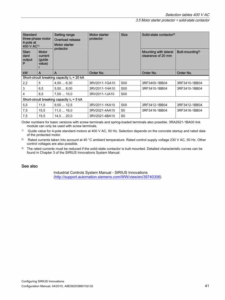
3.5 Motor starter protector + solid-state contactor
CLASS 10, type of coordination 1, short-circuit breaking capacity Iq ≥ 5 kA / 50 kA
NS
B0
_0
19
48
Standard three-phase motor 4-pole at 400 V AC1)
Solid-state contactor2)
Stan-dard output P
Motor current (guide value) I
Setting range Overload release Motor starter protector
Motor starter protector
Mounting with lateral clearance of 20 mm
Butt-mounting3)
kW A A Order No.
Size
Order No. Order No. Short-circuit breaking capacity Iq = 50 kA 0,06 0,2 0,14 ... 0,20 3RV2011-0BA10 S00 0,06 0,2 0,18 ... 0,25 3RV2011-0CA10 S00 0,09 0,3 0,22 ... 0,32 3RV2011-0DA10 S00 0,09 0,3 0,28 ... 0,40 3RV2011-0EA10 S00 0,12 0,4 0,35 ... 0,50 3RV2011-0FA10 S00 0,18 0,6 0,45 ... 0,63 3RV2011-0GA10 S00 0,25 0,85 0,55 ... 0,80 3RV2011-0HA10 S00 0,25 0,85 0,70 ... 1,00 3RV2011-0JA10 S00 0,37 1,1 0,90 ... 1,25 3RV2011-0KA10 S00 0,55 1,5 1,10 ... 1,60 3RV2011-1AA10 S00 0,75 1,9 1,40 ... 2,00 3RV2011-1BA10 S00 0,75 1,9 1,80 ... 2,50 3RV2011-1CA10 S00 1,1 2,7 2,20 ... 3,20 3RV2011-1DA10 S00 1,5 3,6 2,80 ... 4,00 3RV2011-1EA10 S00 1,5 3,6 3,50 ... 5,00 3RV2011-1FA10 S00 2,2 5 4,50 ... 6,30 3RV2011-1GA10 S00
3RF3405-1BB04 3RF3405-1BB04
Selection tables 400 V AC 3.5 Motor starter protector + solid-state contactor
Configuring SIRIUS Innovations Configuration Manual, 04/2010, A8E56203880102-02 41
Standard three-phase motor 4-pole at 400 V AC1)
Solid-state contactor2)
Stan-dard output P
Motor current (guide value) I
Setting range Overload release Motor starter protector
Motor starter protector
Mounting with lateral clearance of 20 mm
Butt-mounting3)
kW A A Order No.
Size
Order No. Order No. Short-circuit breaking capacity Iq = 20 kA 2,2 5 4,50 ... 6,30 3RV2011-1GA10 S00 3RF3405-1BB04 3RF3410-1BB04 3 6,5 5,50 ... 8,00 3RV2011-1HA10 S00 4 8,5 7,00 ... 10,0 3RV2011-1JA10 S00
3RF3410-1BB04 3RF3410-1BB04
Short-circuit breaking capacity Iq = 5 kA 5,5 11,5 9,00 ... 12,5 3RV2011-1KA10 S00 3RF3412-1BB04 3RF3412-1BB04 7,5 15,5 11,0 ... 16,0 3RV2021-4AA10 S0 7,5 15,5 14,0 ... 20,0 3RV2021-4BA10 S0
3RF3416-1BB04 3RF3416-1BB04
Order numbers for basic versions with screw terminals and spring-loaded terminals also possible. 3RA2921-1BA00 link module can only be used with screw terminals.
1) Guide value for 4-pole standard motors at 400 V AC, 50 Hz. Selection depends on the concrete startup and rated data of the protected motor.
2) Rated currents taken into account at 40 °C ambient temperature. Rated control supply voltage 230 V AC, 50 Hz. Other control voltages are also possible.
3) The rated currents must be reduced if the solid-state contactor is butt mounted. Detailed characteristic curves can be found in Chapter 3 of the SIRIUS Innovations System Manual.
See also Industrial Controls System Manual - SIRIUS Innovations (http://support.automation.siemens.com/WW/view/en/39740306)

Selection tables 400 V AC 3.6 Motor starter protector + solid-state reversing contactor
Configuring SIRIUS Innovations 42 Configuration Manual, 04/2010, A8E56203880102-02
3.6 Motor starter protector + solid-state reversing contactor
CLASS 10, type of coordination 1, short-circuit breaking capacity Iq = 10 kA / 50 kA
Standard three-phase motor 4-pole at 400 V AC1)
Solid-state reversing contactor2)
Standard output P
Motor current (guide value) I
Setting range Overload release Motor starter protector
Motor starter protector
Size
Mounting with lateral clearance of 20 mm
Butt-mounting3)
kW A A Order No. Order No. Order No. Short-circuit breaking capacity Iq = 50 kA 0,06 0,2 0,14 ... 0,20 3RV2011-0BA10 S00 0,06 0,2 0,18 ... 0,25 3RV2011-0CA10 S00 0,09 0,3 0,22 ... 0,32 3RV2011-0DA10 S00 0,09 0,3 0,28 ... 0,40 3RV2011-0EA10 S00 0,12 0,4 0,35 ... 0,50 3RV2011-0FA10 S00 0,18 0,6 0,45 ... 0,63 3RV2011-0GA10 S00 0,25 0,85 0,55 ... 0,80 3RV2011-0HA10 S00 0,25 0,85 0,70 ... 1,00 3RV2011-0JA10 S00 0,37 1,1 0,90 ... 1,25 3RV2011-0KA10 S00 0,55 1,5 1,10 ... 1,60 3RV2011-1AA10 S00 0,75 1,9 1,40 ... 2,00 3RV2011-1BA10 S00 0,75 1,9 1,80 ... 2,50 3RV2011-1CA10 S00 1,1 2,7 2,20 ... 3,20 3RV2011-1DA10 S00
3RF3403-1BD04
1,5 3,6 2,80 ... 4,00 3RV2011-1EA10 S00 1,5 3,6 3,50 ... 5,00 3RV2011-1FA10 S00
3RF3403-1BD04
3RF3405-1BD04
2,2 5 4,50 ... 6,30 3RV2011-1GA10 S00 3RF3405-1BD04 —

Selection tables 400 V AC 3.6 Motor starter protector + solid-state reversing contactor
Configuring SIRIUS Innovations Configuration Manual, 04/2010, A8E56203880102-02 43
Standard three-phase motor 4-pole at 400 V AC1)
Solid-state reversing contactor2)
Standard output P
Motor current (guide value) I
Setting range Overload release Motor starter protector
Motor starter protector
Size
Mounting with lateral clearance of 20 mm
Butt-mounting3)
kW A A Order No. Order No. Order No. Short-circuit breaking capacity Iq = 10 kA 2,2 5 4,50 ... 6,30 3RV2011-1GA10 S00 3RF3405-1BD04 3 6,5 5,50 ... 8,00 3RV2011-1HA10 S00 3RF3410-1BD04
3RF3410-1BD04
Order numbers for basic versions with screw terminals and spring-loaded terminals also possible. 3RA2921-1BA00 link module can only be used with screw terminals.
1) Guide value for 4-pole standard motors at 400 V AC, 50 Hz. Selection depends on the concrete startup and rated data of the protected motor.
2) Rated currents taken into account at 40 °C ambient temperature. Rated control supply voltage 230 V AC, 50 Hz. Other control voltages are also possible.
3) The rated currents must be reduced if the solid-state contactor is butt mounted. Detailed characteristic curves can be found in Chapter 3 of the SIRIUS Innovations System Manual.
See also Industrial Controls System Manual - SIRIUS Innovations (http://support.automation.siemens.com/WW/view/en/39740306)
Selection tables 400 V AC 3.7 Motor starter protector + star (wye)-delta starting + 3RU21 thermal overload relay
Configuring SIRIUS Innovations 44 Configuration Manual, 04/2010, A8E56203880102-02
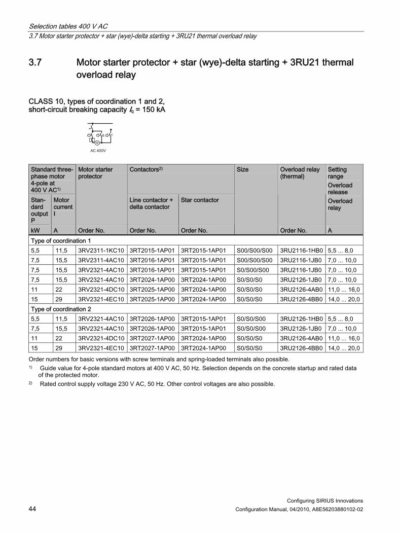
3.7 Motor starter protector + star (wye)-delta starting + 3RU21 thermal overload relay
CLASS 10, types of coordination 1 and 2, short-circuit breaking capacity Iq = 150 kA
M
Standard three-phase motor 4-pole at 400 V AC1)
Contactors2)
Stan-dard output P
Motor current I
Motor starter protector
Line contactor + delta contactor
Star contactor
Overload relay (thermal)
Setting range Overload release Overload relay
kW A Order No. Order No. Order No.
Size
Order No. A Type of coordination 1 5,5 11,5 3RV2311-1KC10 3RT2015-1AP01 3RT2015-1AP01 S00/S00/S00 3RU2116-1HB0 5,5 ... 8,0 7,5 15,5 3RV2311-4AC10 3RT2016-1AP01 3RT2015-1AP01 S00/S00/S00 3RU2116-1JB0 7,0 ... 10,0 7,5 15,5 3RV2321-4AC10 3RT2016-1AP01 3RT2015-1AP01 S0/S00/S00 3RU2116-1JB0 7,0 ... 10,0 7,5 15,5 3RV2321-4AC10 3RT2024-1AP00 3RT2024-1AP00 S0/S0/S0 3RU2126-1JB0 7,0 ... 10,0 11 22 3RV2321-4DC10 3RT2025-1AP00 3RT2024-1AP00 S0/S0/S0 3RU2126-4AB0 11,0 ... 16,015 29 3RV2321-4EC10 3RT2025-1AP00 3RT2024-1AP00 S0/S0/S0 3RU2126-4BB0 14,0 ... 20,0Type of coordination 2 5,5 11,5 3RV2321-4AC10 3RT2026-1AP00 3RT2015-1AP01 S0/S0/S00 3RU2126-1HB0 5,5 ... 8,0 7,5 15,5 3RV2321-4AC10 3RT2026-1AP00 3RT2015-1AP01 S0/S0/S00 3RU2126-1JB0 7,0 ... 10,0 11 22 3RV2321-4DC10 3RT2027-1AP00 3RT2024-1AP00 S0/S0/S0 3RU2126-4AB0 11,0 ... 16,015 29 3RV2321-4EC10 3RT2027-1AP00 3RT2024-1AP00 S0/S0/S0 3RU2126-4BB0 14,0 ... 20,0
Order numbers for basic versions with screw terminals and spring-loaded terminals also possible. 1) Guide value for 4-pole standard motors at 400 V AC, 50 Hz. Selection depends on the concrete startup and rated data
of the protected motor. 2) Rated control supply voltage 230 V AC, 50 Hz. Other control voltages are also possible.

Selection tables 400 V AC 3.8 Motor starter protector + contactor assembly for star-delta start + 3RB22 / 23 / 3 solid-state overload relay, or 3UF7
Configuring SIRIUS Innovations Configuration Manual, 04/2010, A8E56203880102-02 45
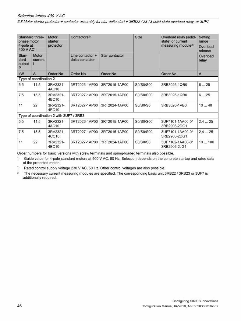
3.8 Motor starter protector + contactor assembly for star-delta start + 3RB22 / 23 / 3 solid-state overload relay, or 3UF7
CLASS 10, types of coordination 1 and 2, short-circuit breaking capacity Iq = 150 kA
M
Standard three-phase motor 4-pole at 400 V AC1)
Contactors2)
Stan-dard output P
Motor current I
Motor starter protector
Line contactor + delta contactor
Star contactor
Overload relay (solid-state) or current measuring module3)
Setting range Overload release Overload relay
kW A Order No. Order No. Order No.
Size
Order No. A Type of coordination 1 5,5 11,5 3RV2311-
4AC10 3RT2016-1AP01 3RT2015-1AP01 S00/S00/S00 3RB3026-1QB0 6 ... 25
5,5 11,5 3RV2321-4AC10
3RT2016-1AP01 3RT2015-1AP01 S0/S00/S00 3RB3026-1QB0 6 ... 25
5,5 11,5 3RV2321-4AC10
3RT2024-1AP00 3RT2024-1AP00 S0/S0/S0 3RB3026-1QB0 6 ... 25
7,5 15,5 3RV2321-4BC10
3RT2025-1AP00 3RT2024-1AP00 S0/S0/S0 3RB3026-1QB0 6 ... 25
11 22 3RV2321-4EC10
3RT2025-1AP00 3RT2024-1AP00 S0/S0/S0 3RB3026-1VB0 10 ... 40
Type of coordination 1 with 3UF7 / 3RB3 5,5 11,5 3RV2311-
4AC10 3RT2016-1AP01 3RT2015-1AP01 S00/S00/S00 3UF7101-1AA00-0/
3RB2906-2DG1 2,4 ... 25
5,5 11,5 3RV2321-4AC10
3RT2016-1AP01 3RT2015-1AP01 S0/S00/S00 3UF7101-1AA00-0/ 3RB2906-2DG1
2,4 ... 25
5,5 11,5 3RV2321-4AC10
3RT2024-1AP00 3RT2024-1AP00 S0/S0/S0 3UF7101-1AA00-0/ 3RB2906-2DG1
2,4 ... 25
7,5 15,5 3RV2321-4CC10
3RT2025-1AP00 3RT2024-1AP00 S0/S0/S0 3UF7101-1AA00-0/ 3RB2906-2DG1
2,4 ... 25
11 22 3RV2321-4EC10
3RT2025-1AP00 3RT2024-1AP00 S0/S0/S0 3UF7102-1AA00-0/ 3RB2906-2JG1
10 ... 100
Selection tables 400 V AC 3.8 Motor starter protector + contactor assembly for star-delta start + 3RB22 / 23 / 3 solid-state overload relay, or 3UF7
Configuring SIRIUS Innovations 46 Configuration Manual, 04/2010, A8E56203880102-02
Standard three-phase motor 4-pole at 400 V AC1)
Contactors2)
Stan-dard output P
Motor current I
Motor starter protector
Line contactor + delta contactor
Star contactor
Overload relay (solid-state) or current measuring module3)
Setting range Overload release Overload relay
kW A Order No. Order No. Order No.
Size
Order No. A Type of coordination 2 5,5 11,5 3RV2321-
4AC10 3RT2026-1AP00 3RT2015-1AP00 S0/S0/S00 3RB3026-1QB0 6 ... 25
7,5 15,5 3RV2321-4BC10
3RT2027-1AP00 3RT2015-1AP00 S0/S0/S00 3RB3026-1QB0 6 ... 25
11 22 3RV2321-4EC10
3RT2027-1AP00 3RT2024-1AP00 S0/S0/S0 3RB3026-1VB0 10 ... 40
Type of coordination 2 with 3UF7 / 3RB3 5,5 11,5 3RV2321-
4AC10 3RT2026-1AP00 3RT2015-1AP00 S0/S0/S00 3UF7101-1AA00-0/
3RB2906-2DG1 2,4 ... 25
7,5 15,5 3RV2321-4CC10
3RT2027-1AP00 3RT2015-1AP00 S0/S0/S00 3UF7101-1AA00-0/ 3RB2906-2DG1
2,4 ... 25
11 22 3RV2321-4EC10
3RT2027-1AP00 3RT2024-1AP00 S0/S0/S0 3UF7102-1AA00-0/ 3RB2906-2JG1
10 ... 100
Order numbers for basic versions with screw terminals and spring-loaded terminals also possible. 1) Guide value for 4-pole standard motors at 400 V AC, 50 Hz. Selection depends on the concrete startup and rated data
of the protected motor. 2) Rated control supply voltage 230 V AC, 50 Hz. Other control voltages are also possible. 3) The necessary current measuring modules are specified. The corresponding basic unit 3RB22 / 3RB23 or 3UF7 is
additionally required.

Selection tables 400 V AC 3.9 Motor starter protector + 3RW30 soft starter
Configuring SIRIUS Innovations Configuration Manual, 04/2010, A8E56203880102-02 47
3.9 Motor starter protector + 3RW30 soft starter
CLASS 10, type of coordination 1,
Standard three-phase motor 4-pole at 400 V AC1) Standard output P
Motor current I
Setting range Overload release Motor starter protector
Motor starter protector Motor protection2)
Soft starter
kW A A Order No. Order No.
Size MSP / 3RW30
Short-circuit breaking capacity Iq = 50 kA 1,5 3,6 2,8 ... 4,0 3RV2011-1EA10 3RW3003-1CB54 S00/- (22.5 mm) Short-circuit breaking capacity Iq = 5 kA 1,5 3,6 3,5 ... 5,0 3RV2011-1FA10 3RW3013-1BB14 S00/S00 3 6,5 5,5 ... 8,0 3RV2011-1HA10 3RW3014-1BB14 S00/S00 4 8,5 7,0 ... 10,0 3RV2011-1JA10 3RW3016-1BB14 S00/S00 5,5 11,5 9,0 ... 12,5 3RV2011-1KA10 3RW3017-1BB14 S00/S00 7,5 15,5 14 ... 20 3RV2021-4BA10 3RW3018-1BB14 S0/S00 Short-circuit breaking capacity Iq = 55 kA 11 22 20 ... 25 3RV2021-4DA10 3RW3026-1BB14 S0/S0 15 29 27 ... 32 3RV2021-4EA10 3RW3027-1BB14 S0/S0 18,5 3) 35 34 ... 40 3RV2021-4FA10 3RW3028-1BB14 S0/S0
Order numbers for basic versions with screw terminals and spring-loaded terminals also possible. 3RA2921-1BA00 link module can only be used with screw terminals.
1) Guide value for 4-pole standard motors at 400 V AC, 50 Hz. Selection depends on the concrete startup and rated data of the protected motor.
2) Rated currents taken into account at 40 °C ambient temperature. Rated control supply voltage 230 V AC, 50 Hz. Other control voltages are also possible.
3) Discrete mounting only, without a link module.

Selection tables 400 V AC 3.10 Motor starter protector + 3RW40 soft starter
Configuring SIRIUS Innovations 48 Configuration Manual, 04/2010, A8E56203880102-02
3.10 Motor starter protector + 3RW40 soft starter
CLASS 10, type of coordination 1, short-circuit breaking capacity Iq = 55 kA
Standard three-phase motor 4-pole at 400 V AC1) Standard output P
Motor current I
Setting range Overload release Motor starter protector
Motor starter protector Motor protection2)
Soft starter
kW A A Order No. Order No.
Size MSP / 3RW40
Short-circuit breaking capacity Iq = 55 kA 7,5 15,5 11 ... 16 3RV2011-4AA10 3RW4024-1BB14 S00/S0 11 22 20 ... 25 3RV2021-4DA10 3RW4026-1BB14 S0/S0 15 29 27 ... 32 3RV2021-4EA10 3RW4027-1BB14 S0/S0 18,5 3) 35 34 ... 40 3RV2021-4FA10 3RW4028-1BB14 S0/S0
Order numbers for basic versions with screw terminals and spring-loaded terminals also possible. 3RA2921-1BA00 link module can only be used with screw terminals.
1) Guide value for 4-pole standard motors at 400 V AC, 50 Hz. Selection depends on the concrete startup and rated data of the protected motor.
2) Rated currents taken into account at 40 °C ambient temperature. Rated control supply voltage 230 V AC, 50 Hz. Other control voltages are also possible.
3) Discrete mounting only, without a link module.

Selection tables 400 V AC 3.11 Motor starter protector + 3RW44 soft starter
Configuring SIRIUS Innovations Configuration Manual, 04/2010, A8E56203880102-02 49
3.11 Motor starter protector + 3RW44 soft starter
CLASS 10, type of coordination 1, short-circuit breaking capacity Iq = 55 kA
Standard three-phase motor 4-pole at 400 V AC1) Standard output P
Motor current I
Setting range Overload release Motor starter protector
Motor starter protector Motor protection2)
Soft starter
kW A A Order No. Order No.
Size MSP / 3RW44
Short-circuit breaking capacity Iq = 55 kA 15 29 27 ... 32 3RV2021-4EA10 3RW4422-1BC44 S0/BG2 18,5 3) 36 34 ... 40 3RV2021-4FA10 3RW4423-1BC44 S0/BG2
Order numbers for basic versions with screw terminals and spring-loaded terminals also possible. 3RA2921-1BA00 link module can only be used with screw terminals.
1) Guide value for 4-pole standard motors at 400 V AC, 50 Hz. Selection depends on the concrete startup and rated data of the protected motor.
2) Rated currents taken into account at 40 °C ambient temperature. Rated control supply voltage 230 V AC, 50 Hz. Other control voltages are also possible. Screw terminals or spring-loaded terminals can be selected.
3) Discrete mounting only, without a link module.

Selection tables 400 V AC 3.11 Motor starter protector + 3RW44 soft starter
Configuring SIRIUS Innovations 50 Configuration Manual, 04/2010, A8E56203880102-02

Configuring SIRIUS Innovations Configuration Manual, 04/2010, A8E56203880102-02 51
Selection tables 500 V AC 44.1 Motor starter protector + contactor
CLASS 10, type of coordination 1, short-circuit breaking capacity Iq = 100 kA
Standard three-phase motor 4-pole at 500 V AC1) Standard output P Motor current I
Setting range Overload release Motor starter protector
Motor starter protector Motor protection
Contactor2)
kW A A Order No. Order No.
Size
0,04 0,11 0,11 ... 0,16 3RV2011-0AA10 3RT2015-1AP01 S00/S00 0,06 0,16 0,14 ... 0,20 3RV2011-0BA10 3RT2015-1AP01 S00/S00 0,09 0,24 0,18 ... 0,25 3RV2011-0CA10 3RT2015-1AP01 S00/S00 0,09 0,24 0,22 ... 0,32 3RV2011-0DA10 3RT2015-1AP01 S00/S00 0,12 0,32 0,28 ... 0,40 3RV2011-0EA10 3RT2015-1AP01 S00/S00 0,18 0,48 0,35 ... 0,50 3RV2011-0FA10 3RT2015-1AP01 S00/S00 0,18 0,48 0,45 ... 0,63 3RV2011-0GA10 3RT2015-1AP01 S00/S00 0,25 0,68 0,55 ... 0,80 3RV2011-0HA10 3RT2015-1AP01 S00/S00 0,37 0,88 0,70 ... 1,00 3RV2011-0JA10 3RT2015-1AP01 S00/S00 0,55 1,2 0,90 ... 1,25 3RV2011-0KA10 3RT2015-1AP01 S00/S00 0,55 1,2 1,1 ... 1,6 3RV2011-1AA10 3RT2015-1AP01 S00/S00 0,75 1,5 1,1 ... 1,6 3RV2011-1AA10 3RT2015-1AP01 S00/S00 0,75 1,5 1,4 ... 2,0 3RV2011-1BA10 3RT2015-1AP01 S00/S00 1,1 2,2 1,8 ... 2,5 3RV2011-1CA10 3RT2015-1AP01 S00/S00 1,5 2,9 2,2 ... 3,2 3RV2011-1DA10 3RT2015-1AP01 S00/S00 2,2 3,9 2,8 ... 4,0 3RV2011-1EA10 3RT2015-1AP01 S00/S00 2,2 3,9 3,5 ... 5,0 3RV2011-1FA10 3RT2015-1AP01 S00/S00 3 5,2 4,5 ... 6,3 3RV2011-1GA10 3RT2015-1AP01 S00/S00 4 6,8 5,5 ... 8,0 3RV2011-1HA10 3RT2016-1AP06 S00/S00 5,5 9,2 7,0 ... 10,0 3RV2011-1JA10 3RT2017-1AP01 S00/S00 7,5 12,4 9,0 ... 12,5 3RV2011-1KA10 3RT2018-1AP01 S00/S00 7,5 12,4 11 ... 16 3RV2011-4AA10 3RT2018-1AP01 S00/S00 11 17,6 14 ... 20 3RV2021-4BA10 3RT2026-1AP00 S0/S0

Selection tables 500 V AC 4.1 Motor starter protector + contactor
Configuring SIRIUS Innovations 52 Configuration Manual, 04/2010, A8E56203880102-02
Standard three-phase motor 4-pole at 500 V AC1) Standard output P Motor current I
Setting range Overload release Motor starter protector
Motor starter protector Motor protection
Contactor2)
kW A A Order No. Order No.
Size
11 17,6 17 ... 22 3RV2021-4CA10 3RT2026-1AP00 S0/S0 15 23 20 ... 25 3RV2021-4DA10 3RT2027-1AP00 S0/S0 18,5 28 23 ... 28 3RV2021-4NA10 3RT2027-1AP00 S0/S0 18,5 28 27 ... 32 3RV2021-4EA10 3RT2027-1AP00 S0/S0 Short-circuit breaking capacity Iq = 36 kA 22 3) 33 30 ... 36 3RV2021-4PA10 3RT1035-1AP00 S0/S2
Order numbers for basic versions with screw terminals and spring-loaded terminals also possible. 1) Guide value for 4-pole standard motors at 500 V AC, 50 Hz. Selection depends on the concrete startup and rated data
of the protected motor. 2) Rated control supply voltage 230 V AC, 50 Hz, other possible. 3) Discrete mounting only, without a link module.
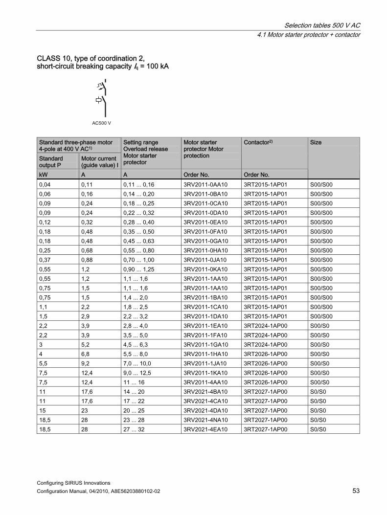
Selection tables 500 V AC 4.1 Motor starter protector + contactor
Configuring SIRIUS Innovations Configuration Manual, 04/2010, A8E56203880102-02 53
CLASS 10, type of coordination 2, short-circuit breaking capacity Iq = 100 kA
Standard three-phase motor 4-pole at 400 V AC1) Standard output P
Motor current (guide value) I
Setting range Overload release Motor starter protector
Motor starter protector Motor protection
Contactor2)
kW A A Order No. Order No.
Size
0,04 0,11 0,11 ... 0,16 3RV2011-0AA10 3RT2015-1AP01 S00/S00 0,06 0,16 0,14 ... 0,20 3RV2011-0BA10 3RT2015-1AP01 S00/S00 0,09 0,24 0,18 ... 0,25 3RV2011-0CA10 3RT2015-1AP01 S00/S00 0,09 0,24 0,22 ... 0,32 3RV2011-0DA10 3RT2015-1AP01 S00/S00 0,12 0,32 0,28 ... 0,40 3RV2011-0EA10 3RT2015-1AP01 S00/S00 0,18 0,48 0,35 ... 0,50 3RV2011-0FA10 3RT2015-1AP01 S00/S00 0,18 0,48 0,45 ... 0,63 3RV2011-0GA10 3RT2015-1AP01 S00/S00 0,25 0,68 0,55 ... 0,80 3RV2011-0HA10 3RT2015-1AP01 S00/S00 0,37 0,88 0,70 ... 1,00 3RV2011-0JA10 3RT2015-1AP01 S00/S00 0,55 1,2 0,90 ... 1,25 3RV2011-0KA10 3RT2015-1AP01 S00/S00 0,55 1,2 1,1 ... 1,6 3RV2011-1AA10 3RT2015-1AP01 S00/S00 0,75 1,5 1,1 ... 1,6 3RV2011-1AA10 3RT2015-1AP01 S00/S00 0,75 1,5 1,4 ... 2,0 3RV2011-1BA10 3RT2015-1AP01 S00/S00 1,1 2,2 1,8 ... 2,5 3RV2011-1CA10 3RT2015-1AP01 S00/S00 1,5 2,9 2,2 ... 3,2 3RV2011-1DA10 3RT2015-1AP01 S00/S00 2,2 3,9 2,8 ... 4,0 3RV2011-1EA10 3RT2024-1AP00 S00/S0 2,2 3,9 3,5 ... 5,0 3RV2011-1FA10 3RT2024-1AP00 S00/S0 3 5,2 4,5 ... 6,3 3RV2011-1GA10 3RT2024-1AP00 S00/S0 4 6,8 5,5 ... 8,0 3RV2011-1HA10 3RT2026-1AP00 S00/S0 5,5 9,2 7,0 ... 10,0 3RV2011-1JA10 3RT2026-1AP00 S00/S0 7,5 12,4 9,0 ... 12,5 3RV2011-1KA10 3RT2026-1AP00 S00/S0 7,5 12,4 11 ... 16 3RV2011-4AA10 3RT2026-1AP00 S00/S0 11 17,6 14 ... 20 3RV2021-4BA10 3RT2027-1AP00 S0/S0 11 17,6 17 ... 22 3RV2021-4CA10 3RT2027-1AP00 S0/S0 15 23 20 ... 25 3RV2021-4DA10 3RT2027-1AP00 S0/S0 18,5 28 23 ... 28 3RV2021-4NA10 3RT2027-1AP00 S0/S0 18,5 28 27 ... 32 3RV2021-4EA10 3RT2027-1AP00 S0/S0

Selection tables 500 V AC 4.1 Motor starter protector + contactor
Configuring SIRIUS Innovations 54 Configuration Manual, 04/2010, A8E56203880102-02
Standard three-phase motor 4-pole at 400 V AC1) Standard output P
Motor current (guide value) I
Setting range Overload release Motor starter protector
Motor starter protector Motor protection
Contactor2)
kW A A Order No. Order No.
Size
Short-circuit breaking capacity Iq = 36 kA 22 3) 33 30 ... 36 3RV2021-4PA10 3RT1035-1AP00 S0/S2
Order numbers for basic versions with screw terminals and spring-loaded terminals also possible. 1) Guide value for 4-pole standard motors at 500 V AC, 50 Hz. Selection depends on the concrete startup and rated data
of the protected motor. 2) Rated control supply voltage 230 V AC, 50 Hz, other control voltages possible. 3) Discrete mounting only, without a link module.

Selection tables 500 V AC 4.2 Motor starter protector + contactor + thermal overload relay
Configuring SIRIUS Innovations Configuration Manual, 04/2010, A8E56203880102-02 55
4.2 Motor starter protector + contactor + thermal overload relay
CLASS 10, type of coordination 1, short-circuit breaking capacity Iq = 100 kA
Standard three-phase motor 4-pole at 400 V AC1) Standard output P
Motor current I
Motor starter protector Starter protection
Contactor2) Thermal overload relay
Setting range Overload release Overload relay
kW A Order No. Order No.
Size
Order No. A 0,04 0,11 3RV2311-0AC10 3RT2015-1AP01 S00/S00/S00 3RU2116-0AB0 0,11 ... 0,16 0,06 0,16 3RV2311-0BC10 3RT2015-1AP01 S00/S00/S00 3RU2116-0BB0 0,14 ... 0,20 0,09 0,24 3RV2311-0CC10 3RT2015-1AP01 S00/S00/S00 3RU2116-0CB0 0,18 ... 0,25 0,09 0,24 3RV2311-0DC10 3RT2015-1AP01 S00/S00/S00 3RU2116-0DB0 0,22 ... 0,32 0,12 0,32 3RV2311-0EC10 3RT2015-1AP01 S00/S00/S00 3RU2116-0EB0 0,28 ... 0,40 0,18 0,48 3RV2311-0FC10 3RT2015-1AP01 S00/S00/S00 3RU2116-0FB0 0,35 ... 0,50 0,18 0,48 3RV2311-0GC10 3RT2015-1AP01 S00/S00/S00 3RU2116-0GB0 0,45 ... 0,63 0,25 0,68 3RV2311-0HC10 3RT2015-1AP01 S00/S00/S00 3RU2116-0HB0 0,55 ... 0,80 0,37 0,88 3RV2311-0JC10 3RT2015-1AP01 S00/S00/S00 3RU2116-0JB0 0,70 ... 1,00 0,55 1,2 3RV2311-0KC10 3RT2015-1AP01 S00/S00/S00 3RU2116-0KB0 0,90 ... 1,25 0,55 1,2 3RV2311-1AC10 3RT2015-1AP01 S00/S00/S00 3RU2116-1AB0 1,1 ... 1,6 0,75 1,5 3RV2311-1AC10 3RT2015-1AP01 S00/S00/S00 3RU2116-1AB0 1,1 ... 1,6 0,75 1,5 3RV2311-1BC10 3RT2015-1AP01 S00/S00/S00 3RU2116-1BB0 1,4 ... 2,0 1,1 2,2 3RV2311-1CC10 3RT2015-1AP01 S00/S00/S00 3RU2116-1CB0 1,8 ... 2,5 1,5 2,9 3RV2311-1DC10 3RT2015-1AP01 S00/S00/S00 3RU2116-1DB0 2,2 ... 3,2 2,2 3,9 3RV2311-1EC10 3RT2015-1AP01 S00/S00/S00 3RU2116-1EB0 2,8 ... 4,0 2,2 3,9 3RV2311-1FC10 3RT2015-1AP01 S00/S00/S00 3RU2116-1FB0 3,5 ... 5,0 3 5,2 3RV2311-1GC10 3RT2015-1AP01 S00/S00/S00 3RU2116-1GB0 4,5 ... 6,3 4 6,8 3RV2311-1HC10 3RT2016-1AP06 S00/S00/S00 3RU2116-1HB0 5,5 ... 8,0 5,5 9,2 3RV2311-1JC10 3RT2017-1AP01 S00/S00/S00 3RU2116-1JB0 7,0 ... 10,0 7,5 12,4 3RV2311-1KC10 3RT2018-1AP01 S00/S00/S00 3RU2116-1KB0 9,0 ... 12,5 7,5 12,4 3RV2311-4AC10 3RT2018-1AP01 S00/S00/S00 3RU2116-4AB0 11 ... 16 11 17,6 3RV2321-4BC10 3RT2026-1AP00 S0/S0/S0 3RU2126-4BB0 14 ... 20 11 17,6 3RV2321-4CC10 3RT2026-1AP00 S0/S0/S0 3RU2126-4CB0 17 ... 22 15 23 3RV2321-4DC10 3RT2027-1AP00 S0/S0/S0 3RU2126-4DB0 20 ... 25

Selection tables 500 V AC 4.2 Motor starter protector + contactor + thermal overload relay
Configuring SIRIUS Innovations 56 Configuration Manual, 04/2010, A8E56203880102-02
Standard three-phase motor 4-pole at 400 V AC1) Standard output P
Motor current I
Motor starter protector Starter protection
Contactor2) Thermal overload relay
Setting range Overload release Overload relay
kW A Order No. Order No.
Size
Order No. A 18,5 28 3RV2321-4NC10 3RT2027-1AP00 S0/S0/S0 3RU2126-4NB0 23 ... 28 18,5 28 3RV2321-4EC10 3RT2027-1AP00 S0/S0/S0 3RU2126-4EB0 27 ... 32 Short-circuit breaking capacity Iq = 36 kA 22 3) 33 3RV2321-4PC10 3RT1035-1AP00 S0/S2/S0 3RU2126-4PB0 30 ... 36 22 3) 33 3RV2321-4PC10 3RT1035-1AP00 S0/S2/S2 3RU1136-4FB0 28 ... 40
Order numbers for basic versions with screw terminals and spring-loaded terminals also possible. 1) Guide value for 4-pole standard motors at 500 V AC, 50 Hz. Selection depends on the concrete startup and rated data
of the protected motor. 2) Rated control supply voltage 230 V AC, 50 Hz, other control voltages possible. 3) Discrete mounting only, without a link module.
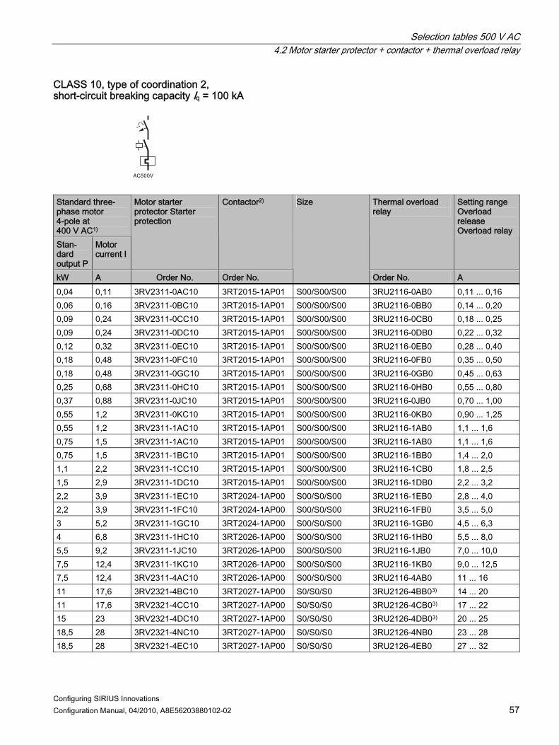
Selection tables 500 V AC 4.2 Motor starter protector + contactor + thermal overload relay
Configuring SIRIUS Innovations Configuration Manual, 04/2010, A8E56203880102-02 57
CLASS 10, type of coordination 2, short-circuit breaking capacity Iq = 100 kA
Standard three-phase motor 4-pole at 400 V AC1) Stan- dard output P
Motor current I
Motor starter protector Starter protection
Contactor2) Thermal overload relay
Setting range Overload release Overload relay
kW A Order No. Order No.
Size
Order No. A 0,04 0,11 3RV2311-0AC10 3RT2015-1AP01 S00/S00/S00 3RU2116-0AB0 0,11 ... 0,16 0,06 0,16 3RV2311-0BC10 3RT2015-1AP01 S00/S00/S00 3RU2116-0BB0 0,14 ... 0,20 0,09 0,24 3RV2311-0CC10 3RT2015-1AP01 S00/S00/S00 3RU2116-0CB0 0,18 ... 0,25 0,09 0,24 3RV2311-0DC10 3RT2015-1AP01 S00/S00/S00 3RU2116-0DB0 0,22 ... 0,32 0,12 0,32 3RV2311-0EC10 3RT2015-1AP01 S00/S00/S00 3RU2116-0EB0 0,28 ... 0,40 0,18 0,48 3RV2311-0FC10 3RT2015-1AP01 S00/S00/S00 3RU2116-0FB0 0,35 ... 0,50 0,18 0,48 3RV2311-0GC10 3RT2015-1AP01 S00/S00/S00 3RU2116-0GB0 0,45 ... 0,63 0,25 0,68 3RV2311-0HC10 3RT2015-1AP01 S00/S00/S00 3RU2116-0HB0 0,55 ... 0,80 0,37 0,88 3RV2311-0JC10 3RT2015-1AP01 S00/S00/S00 3RU2116-0JB0 0,70 ... 1,00 0,55 1,2 3RV2311-0KC10 3RT2015-1AP01 S00/S00/S00 3RU2116-0KB0 0,90 ... 1,25 0,55 1,2 3RV2311-1AC10 3RT2015-1AP01 S00/S00/S00 3RU2116-1AB0 1,1 ... 1,6 0,75 1,5 3RV2311-1AC10 3RT2015-1AP01 S00/S00/S00 3RU2116-1AB0 1,1 ... 1,6 0,75 1,5 3RV2311-1BC10 3RT2015-1AP01 S00/S00/S00 3RU2116-1BB0 1,4 ... 2,0 1,1 2,2 3RV2311-1CC10 3RT2015-1AP01 S00/S00/S00 3RU2116-1CB0 1,8 ... 2,5 1,5 2,9 3RV2311-1DC10 3RT2015-1AP01 S00/S00/S00 3RU2116-1DB0 2,2 ... 3,2 2,2 3,9 3RV2311-1EC10 3RT2024-1AP00 S00/S0/S00 3RU2116-1EB0 2,8 ... 4,0 2,2 3,9 3RV2311-1FC10 3RT2024-1AP00 S00/S0/S00 3RU2116-1FB0 3,5 ... 5,0 3 5,2 3RV2311-1GC10 3RT2024-1AP00 S00/S0/S00 3RU2116-1GB0 4,5 ... 6,3 4 6,8 3RV2311-1HC10 3RT2026-1AP00 S00/S0/S00 3RU2116-1HB0 5,5 ... 8,0 5,5 9,2 3RV2311-1JC10 3RT2026-1AP00 S00/S0/S00 3RU2116-1JB0 7,0 ... 10,0 7,5 12,4 3RV2311-1KC10 3RT2026-1AP00 S00/S0/S00 3RU2116-1KB0 9,0 ... 12,5 7,5 12,4 3RV2311-4AC10 3RT2026-1AP00 S00/S0/S00 3RU2116-4AB0 11 ... 16 11 17,6 3RV2321-4BC10 3RT2027-1AP00 S0/S0/S0 3RU2126-4BB03) 14 ... 20 11 17,6 3RV2321-4CC10 3RT2027-1AP00 S0/S0/S0 3RU2126-4CB03) 17 ... 22 15 23 3RV2321-4DC10 3RT2027-1AP00 S0/S0/S0 3RU2126-4DB03) 20 ... 25 18,5 28 3RV2321-4NC10 3RT2027-1AP00 S0/S0/S0 3RU2126-4NB0 23 ... 28 18,5 28 3RV2321-4EC10 3RT2027-1AP00 S0/S0/S0 3RU2126-4EB0 27 ... 32

Selection tables 500 V AC 4.2 Motor starter protector + contactor + thermal overload relay
Configuring SIRIUS Innovations 58 Configuration Manual, 04/2010, A8E56203880102-02
Standard three-phase motor 4-pole at 400 V AC1) Stan- dard output P
Motor current I
Motor starter protector Starter protection
Contactor2) Thermal overload relay
Setting range Overload release Overload relay
kW A Order No. Order No.
Size
Order No. A Short-circuit breaking capacity Iq = 36 kA 22 4) 33 3RV2321-4PC10 3RT1035-1AP00 S0/S2/S0 3RU2126-4PB0 30 ... 36 22 4) 33 3RV2321-4PC10 3RT1035-1AP00 S0/S2/S2 3RU1136-4FB0 28 ... 40
Order numbers for basic versions with screw terminals and spring-loaded terminals also possible. 1) Guide value for 4-pole standard motors at 500 V AC, 50 Hz. Selection depends on the concrete startup and rated data
of the protected motor. 2) Rated control supply voltage 230 V AC, 50 Hz, other control voltages possible. 3) Can also be used in size S00 (3RU2116). 4) Discrete mounting only, without a link module.

Selection tables 500 V AC 4.3 Motor starter protector + contactor + 3RB3 solid-state overload relay
Configuring SIRIUS Innovations Configuration Manual, 04/2010, A8E56203880102-02 59
4.3 Motor starter protector + contactor + 3RB3 solid-state overload relay
Type of coordination 1, short-circuit breaking capacity Iq = 100 kA
Standard three-phase motor 4-pole at 400 V AC1) Stan-dard output P
Motor current I
Motor starter protector Starter protection3)
Contactor2) Overload relay (solid-state)
Setting range Overload release Overload relay
kW A
Setting range Overload release Motor starter protector
Order No. Order No.
Size
Order No. A CLASS 10 0,04 0,11 0,2 3RV2311-0BC10 3RT2015-1AP01 S00/S00/S00 3RB3016-1RB0 0,1 ... 0,40 0,06 0,16 0,2 3RV2311-0BC10 3RT2015-1AP01 S00/S00/S00 3RB3016-1RB0 0,1 ... 0,40 0,09 0,24 0,32 3RV2311-0DC10 3RT2015-1AP01 S00/S00/S00 3RB3016-1RB0 0,1 ... 0,40 0,12 0,32 0,4 3RV2311-0EC10 3RT2015-1AP01 S00/S00/S00 3RB3016-1NB0 0,3 ... 1,25 0,18 0,48 0,63 3RV2311-0GC10 3RT2015-1AP01 S00/S00/S00 3RB3016-1NB0 0,3 ... 1,25 0,25 0,68 0,8 3RV2311-0HC10 3RT2015-1AP01 S00/S00/S00 3RB3016-1NB0 0,3 ... 1,25 0,37 0,88 1 3RV2311-0JC10 3RT2015-1AP01 S00/S00/S00 3RB3016-1NB0 0,3 ... 1,25 0,55 1,20 1,25 3RV2311-0KC10 3RT2015-1AP01 S00/S00/S00 3RB3016-1PB0 1,0 ... 4,00 0,75 1,50 1,6 3RV2311-1AC10 3RT2015-1AP01 S00/S00/S00 3RB3016-1PB0 1,0 ... 4,00 1,1 2,20 2,5 3RV2311-1CC10 3RT2015-1AP01 S00/S00/S00 3RB3016-1PB0 1,0 ... 4,00 1,5 2,90 3,2 3RV2311-1DC10 3RT2015-1AP01 S00/S00/S00 3RB3016-1PB0 1,0 ... 4,00 2,2 3,90 5 3RV2311-1FC10 3RT2015-1AP01 S00/S00/S00 3RB3016-1PB0 1,0 ... 4,00 2,2 3,90 5 3RV2311-1FC10 3RT2015-1AP01 S00/S00/S00 3RB3016-1PB0 1,0 ... 4,00 3 5,20 8 3RV2311-1HC10 3RT2016-1AP01 S00/S00/S00 3RB3016-1SB0 3,0 ... 12,00 4 6,80 8 3RV2311-1HC10 3RT2016-1AP01 S00/S00/S00 3RB3016-1SB0 3,0 ... 12,00 5,5 9,20 10 3RV2311-1JC10 3RT2017-1AP01 S00/S00/S00 3RB3016-1SB0 3,0 ... 12,00 7,5 12,40 16 3RV2321-4AC10 3RT2026-1AP00 S0/S0/S0 3RB3026-1QB0 6,0 ... 25,00 11 17,60 22 3RV2321-4CC10 3RT2026-1AP00 S0/S0/S0 3RB3026-1QB0 6,0 ... 25,00 15 23,00 32 3RV2321-4EC10 3RT2027-1AP00 S0/S0/S0 3RB3026-1VB0 10,0 ... 40,00

Selection tables 500 V AC 4.3 Motor starter protector + contactor + 3RB3 solid-state overload relay
Configuring SIRIUS Innovations 60 Configuration Manual, 04/2010, A8E56203880102-02
Standard three-phase motor 4-pole at 400 V AC1) Stan-dard output P
Motor current I
Motor starter protector Starter protection3)
Contactor2) Overload relay (solid-state)
Setting range Overload release Overload relay
kW A
Setting range Overload release Motor starter protector
Order No. Order No.
Size
Order No. A CLASS 20 0,04 0,11 0,32 3RV2311-0DC10 3RT2015-1AP01 S00/S00/S00 3RB3016-2RB0 0,1 ... 0,40 0,06 0,16 0,32 3RV2311-0DC10 3RT2015-1AP01 S00/S00/S00 3RB3016-2RB0 0,1 ... 0,40 0,09 0,24 0,5 ... 0,63 3RV2011-0GA10 3RT2015-1AP01 S00/S00/S00 3RB3016-2RB0 0,1 ... 0,40 0,12 0,32 0,6 ... 0,8 3RV2011-0HA10 3RT2015-1AP01 S00/S00/S00 3RB3016-2NB0 0,3 ... 1,25 0,18 0,48 0,9 ... 1,25 3RV2011-0KA10 3RT2015-1AP01 S00/S00/S00 3RB3016-2NB0 0,3 ... 1,25 0,25 0,68 1,1 ... 1,6 3RV2011-1AA10 3RT2015-1AP01 S00/S00/S00 3RB3016-2NB0 0,3 ... 1,25 0,37 0,88 1,4 ... 2 3RV2011-1BA10 3RT2015-1AP01 S00/S00/S00 3RB3016-2NB0 0,3 ... 1,25 0,55 1,20 1,8 ... 2,5 3RV2011-1CA10 3RT2015-1AP01 S00/S00/S00 3RB3016-2PB0 1,0 ... 4,00 0,75 1,50 2,2 ... 3,2 3RV2011-1DA10 3RT2015-1AP01 S00/S00/S00 3RB3016-2PB0 1,0 ... 4,00 1,1 2,20 3,5 ... 5 3RV2011-1FA10 3RT2015-1AP01 S00/S00/S00 3RB3016-2PB0 1,0 ... 4,00 1,5 2,90 4,5 ... 6,3 3RV2011-1GA10 3RT2015-1AP01 S00/S00/S00 3RB3016-2PB0 1,0 ... 4,00 2,2 3,90 7,0 ... 10 3RV2011-1JA10 3RT2017-1AP01 S00/S00/S00 3RB3016-2SB0 3,0 ... 12,00 3 5,20 9,0 ... 12,5 3RV2011-1KA10 3RT2018-1AP01 S00/S00/S00 3RB3016-2SB0 3,0 ... 12,00 4 6,80 11,0 ... 16 3RV2011-4AA10 3RT2018-1AP01 S00/S00/S00 3RB3016-2SB0 3,0 ... 12,00 5,5 9,20 14,0 ... 20 3RV2021-4BA10 3RT2026-1AP00 S0/S0/S0 3RB3026-2QB0 6,0 ... 25,00 7,5 12,40 20,0 ... 25 3RV2021-4DA10 3RT2027-1AP00 S0/S0/S0 3RB3026-2QB0 6,0 ... 25,00 CLASS 30 0,04 0,11 0,32 3RV2311-0DC10 3RT2015-1AP01 S00/S00/S00 3RB3113-4RB0 0,1 ... 0,40 0,06 0,16 0,4 ... 0,5 3RV2011-0FA10 3RT2015-1AP01 S00/S00/S00 3RB3113-4RB0 0,1 ... 0,40 0,09 0,24 0,6 ... 0,8 3RV2011-0HA10 3RT2015-1AP01 S00/S00/S00 3RB3113-4RB0 0,1 ... 0,40 0,12 0,32 0,9 ... 1,25 3RV2011-0KA10 3RT2015-1AP01 S00/S00/S00 3RB3113-4NB0 0,3 ... 1,25 0,18 0,48 1,1 ... 1,6 3RV2011-1AA10 3RT2015-1AP01 S00/S00/S00 3RB3113-4NB0 0,3 ... 1,25 0,25 0,68 1,4 ... 2 3RV2011-1BA10 3RT2015-1AP01 S00/S00/S00 3RB3113-4NB0 0,3 ... 1,25 0,37 0,88 1,8 ... 2,5 3RV2011-1CA10 3RT2015-1AP01 S00/S00/S00 3RB3113-4NB0 0,3 ... 1,25 0,55 1,20 2,8 ... 4 3RV2011-1EA10 3RT2015-1AP01 S00/S00/S00 3RB3113-4PB0 1,0 ... 4,00 0,75 1,50 3,5 ... 5 3RV2011-1FA10 3RT2015-1AP01 S00/S00/S00 3RB3113-4PB0 1,0 ... 4,00 1,1 2,20 4,5 ... 6,3 3RV2011-1GA10 3RT2015-1AP01 S00/S00/S00 3RB3113-4PB0 1,0 ... 4,00 1,5 2,90 7,0 ... 10 3RV2011-1JA10 3RT2017-1AP01 S00/S00/S00 3RB3113-4PB0 1,0 ... 4,00 2,2 3,90 9,0 ... 12,5 3RV2011-1KA10 3RT2018-1AP01 S00/S00/S00 3RB3113-4RB0 3,0 ... 12,00
Order numbers for basic versions with screw terminals and spring-loaded terminals also possible. 1) Guide value for 4-pole standard motors at 500 V AC, 50 Hz. Selection depends on the concrete startup and rated data
of the protected motor. 2) Rated control supply voltage 230 V AC, 50 Hz, other control voltages possible. 3RA2921-1BA00 link module can only
be used with screw terminals. 3) The motor starter protector is to be set to maximum current value.

Selection tables 500 V AC 4.3 Motor starter protector + contactor + 3RB3 solid-state overload relay
Configuring SIRIUS Innovations Configuration Manual, 04/2010, A8E56203880102-02 61
Type of coordination 2, short-circuit breaking capacity Iq = 100 kA
Standard three-phase motor 4-pole at 400 V AC1) Stan-dard output P
Motor current I
Motor starter protector Starter protection3)
Contactor2) Overload relay (solid-state)
Setting range Overload release Overload relay
kW A
Setting range Overload release Motor starter protector
Order No. Order No.
Size
Order No. A CLASS 10 0,2 0,2 0,2 3RV2311-0BC10 3RT2015-1AP01 S00/S00/S00 3RB3016-1RB0 0,1 ... 0,40 0,2 0,2 0,2 3RV2311-0BC10 3RT2015-1AP01 S00/S00/S00 3RB3016-1RB0 0,1 ... 0,40 0,32 0,32 0,32 3RV2311-0DC10 3RT2015-1AP01 S00/S00/S00 3RB3016-1RB0 0,1 ... 0,40 0,4 0,4 0,4 3RV2311-0EC10 3RT2015-1AP01 S00/S00/S00 3RB3016-1NB0 0,3 ... 1,25 0,63 0,63 0,63 3RV2311-0GC10 3RT2015-1AP01 S00/S00/S00 3RB3016-1NB0 0,3 ... 1,25 0,8 0,8 0,8 3RV2311-0HC10 3RT2015-1AP01 S00/S00/S00 3RB3016-1NB0 0,3 ... 1,25 1 1 1 3RV2311-0JC10 3RT2015-1AP01 S00/S00/S00 3RB3016-1NB0 0,3 ... 1,25 1,25 1,25 1,25 3RV2311-0KC10 3RT2015-1AP01 S00/S00/S00 3RB3016-1PB0 1,0 ... 4,00 1,6 1,6 1,6 3RV2311-1AC10 3RT2015-1AP01 S00/S00/S00 3RB3016-1PB0 1,0 ... 4,00 2,5 2,5 2,5 3RV2311-1CC10 3RT2015-1AP01 S00/S00/S00 3RB3016-1PB0 1,0 ... 4,00 3,2 3,2 3,2 3RV2311-1DC10 3RT2015-1AP01 S00/S00/S00 3RB3016-1PB0 1,0 ... 4,00 5 5 5 3RV2311-1FC10 3RT2024-1AP00 S00/S0/S0 3RB3026-1SB0 3,0 ... 12,00 5 5 5 3RV2311-1FC10 3RT2024-1AP00 S00/S0/S0 3RB3026-1SB0 3,0 ... 12,00 8 8 8 3RV2311-1HC10 3RT2026-1AP00 S00/S0/S0 3RB3026-1SB0 3,0 ... 12,00 8 8 8 3RV2311-1HC10 3RT2026-1AP00 S00/S0/S0 3RB3026-1SB0 3,0 ... 12,00 16 16 16 3RV2321-4AC10 3RT2026-1AP00 S0/S0/S0 3RB3026-1QB0 6,0 ... 25,00 10 10 10 3RV2311-1JC10 3RT2026-1AP00 S00/S0/S0 3RB3026-1SB0 3,0 ... 12,00 22 22 22 3RV2321-4CC10 3RT2027-1AP00 S0/S0/S0 3RB3026-1QB0 6,0 ... 25,00 0,2 0,2 0,2 3RV2321-4EC10 3RT2027-1AP00 S0/S0/S0 3RB3026-1VB0 10,0 ... 40,00 CLASS 20 0,04 0,11 0,32 3RV2311-0DC10 3RT2015-1AP01 S00/S00/S00 3RB3016-2RB0 0,1 ... 0,40 0,06 0,16 0,32 3RV2311-0DC10 3RT2015-1AP01 S00/S00/S00 3RB3016-2RB0 0,1 ... 0,40 0,09 0,24 0,5 ... 0,63 3RV2011-0GA10 3RT2015-1AP01 S00/S00/S00 3RB3016-2RB0 0,1 ... 0,40 0,12 0,32 0,6 ... 0,8 3RV2011-0HA10 3RT2015-1AP01 S00/S00/S00 3RB3016-2NB0 0,3 ... 1,25 0,18 0,48 0,9 ... 1,25 3RV2011-0KA10 3RT2015-1AP01 S00/S00/S00 3RB3016-2NB0 0,3 ... 1,25 0,25 0,68 1,1 ... 1,6 3RV2011-1AA10 3RT2015-1AP01 S00/S00/S00 3RB3016-2NB0 0,3 ... 1,25
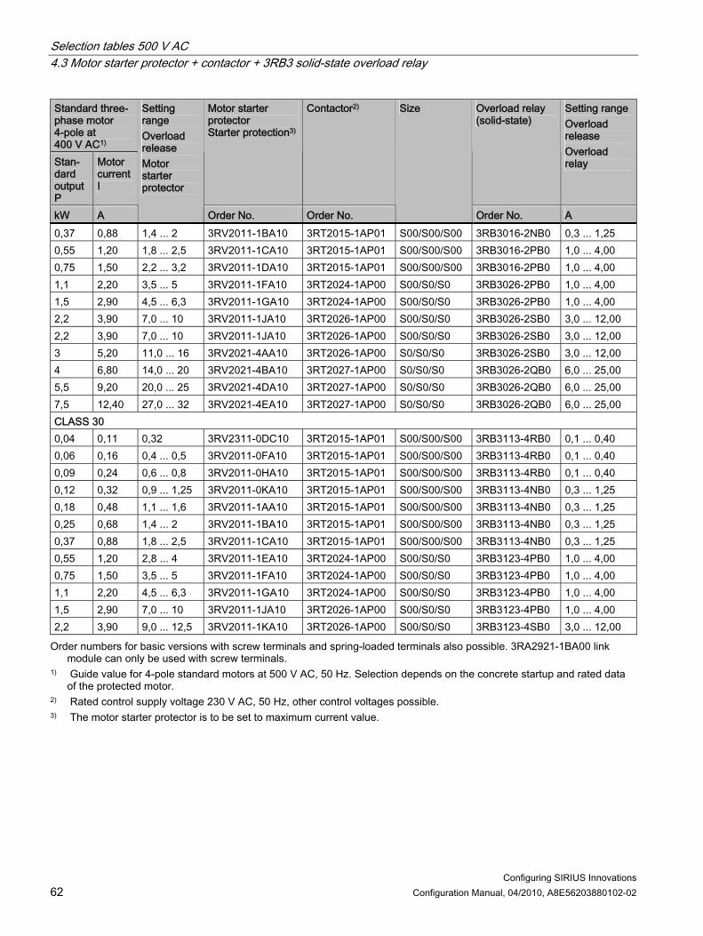
Selection tables 500 V AC 4.3 Motor starter protector + contactor + 3RB3 solid-state overload relay
Configuring SIRIUS Innovations 62 Configuration Manual, 04/2010, A8E56203880102-02
Standard three-phase motor 4-pole at 400 V AC1) Stan-dard output P
Motor current I
Motor starter protector Starter protection3)
Contactor2) Overload relay (solid-state)
Setting range Overload release Overload relay
kW A
Setting range Overload release Motor starter protector
Order No. Order No.
Size
Order No. A 0,37 0,88 1,4 ... 2 3RV2011-1BA10 3RT2015-1AP01 S00/S00/S00 3RB3016-2NB0 0,3 ... 1,25 0,55 1,20 1,8 ... 2,5 3RV2011-1CA10 3RT2015-1AP01 S00/S00/S00 3RB3016-2PB0 1,0 ... 4,00 0,75 1,50 2,2 ... 3,2 3RV2011-1DA10 3RT2015-1AP01 S00/S00/S00 3RB3016-2PB0 1,0 ... 4,00 1,1 2,20 3,5 ... 5 3RV2011-1FA10 3RT2024-1AP00 S00/S0/S0 3RB3026-2PB0 1,0 ... 4,00 1,5 2,90 4,5 ... 6,3 3RV2011-1GA10 3RT2024-1AP00 S00/S0/S0 3RB3026-2PB0 1,0 ... 4,00 2,2 3,90 7,0 ... 10 3RV2011-1JA10 3RT2026-1AP00 S00/S0/S0 3RB3026-2SB0 3,0 ... 12,00 2,2 3,90 7,0 ... 10 3RV2011-1JA10 3RT2026-1AP00 S00/S0/S0 3RB3026-2SB0 3,0 ... 12,00 3 5,20 11,0 ... 16 3RV2021-4AA10 3RT2026-1AP00 S0/S0/S0 3RB3026-2SB0 3,0 ... 12,00 4 6,80 14,0 ... 20 3RV2021-4BA10 3RT2027-1AP00 S0/S0/S0 3RB3026-2QB0 6,0 ... 25,00 5,5 9,20 20,0 ... 25 3RV2021-4DA10 3RT2027-1AP00 S0/S0/S0 3RB3026-2QB0 6,0 ... 25,00 7,5 12,40 27,0 ... 32 3RV2021-4EA10 3RT2027-1AP00 S0/S0/S0 3RB3026-2QB0 6,0 ... 25,00 CLASS 30 0,04 0,11 0,32 3RV2311-0DC10 3RT2015-1AP01 S00/S00/S00 3RB3113-4RB0 0,1 ... 0,40 0,06 0,16 0,4 ... 0,5 3RV2011-0FA10 3RT2015-1AP01 S00/S00/S00 3RB3113-4RB0 0,1 ... 0,40 0,09 0,24 0,6 ... 0,8 3RV2011-0HA10 3RT2015-1AP01 S00/S00/S00 3RB3113-4RB0 0,1 ... 0,40 0,12 0,32 0,9 ... 1,25 3RV2011-0KA10 3RT2015-1AP01 S00/S00/S00 3RB3113-4NB0 0,3 ... 1,25 0,18 0,48 1,1 ... 1,6 3RV2011-1AA10 3RT2015-1AP01 S00/S00/S00 3RB3113-4NB0 0,3 ... 1,25 0,25 0,68 1,4 ... 2 3RV2011-1BA10 3RT2015-1AP01 S00/S00/S00 3RB3113-4NB0 0,3 ... 1,25 0,37 0,88 1,8 ... 2,5 3RV2011-1CA10 3RT2015-1AP01 S00/S00/S00 3RB3113-4NB0 0,3 ... 1,25 0,55 1,20 2,8 ... 4 3RV2011-1EA10 3RT2024-1AP00 S00/S0/S0 3RB3123-4PB0 1,0 ... 4,00 0,75 1,50 3,5 ... 5 3RV2011-1FA10 3RT2024-1AP00 S00/S0/S0 3RB3123-4PB0 1,0 ... 4,00 1,1 2,20 4,5 ... 6,3 3RV2011-1GA10 3RT2024-1AP00 S00/S0/S0 3RB3123-4PB0 1,0 ... 4,00 1,5 2,90 7,0 ... 10 3RV2011-1JA10 3RT2026-1AP00 S00/S0/S0 3RB3123-4PB0 1,0 ... 4,00 2,2 3,90 9,0 ... 12,5 3RV2011-1KA10 3RT2026-1AP00 S00/S0/S0 3RB3123-4SB0 3,0 ... 12,00
Order numbers for basic versions with screw terminals and spring-loaded terminals also possible. 3RA2921-1BA00 link module can only be used with screw terminals.
1) Guide value for 4-pole standard motors at 500 V AC, 50 Hz. Selection depends on the concrete startup and rated data of the protected motor.
2) Rated control supply voltage 230 V AC, 50 Hz, other control voltages possible. 3) The motor starter protector is to be set to maximum current value.

Selection tables 500 V AC 4.4 Motor starter protector + contactor + 3RB22, 3RB23 solid-state overload relay, or 3UF7
Configuring SIRIUS Innovations Configuration Manual, 04/2010, A8E56203880102-02 63
4.4 Motor starter protector + contactor + 3RB22, 3RB23 solid-state overload relay, or 3UF7
Type of coordination 2, short-circuit breaking capacity Iq = 100 kA
Standard three-phase motor 4-pole at 400 V AC1) Stan-dard output P
Motor current I
Motor starter protector Starter protection3)
Contactor2) Overload relay (solid-state)
Setting range Overload release Overload relay
kW A
Setting range Overload release Motor starter protector
Order No. Order No.
Size
Order No. A CLASS 10 0,12 0,32 0,4 3RV2311-0EC10 3RT2015-1AP01 S00/S00 3UF7100-1AA00-0/
3RB2906-2BG1 0,3 ... 3,00
0,18 0,48 0,63 3RV2311-0GC10 3RT2015-1AP01 S00/S00 3UF7100-1AA00-0/ 3RB2906-2BG1
0,3 ... 3,00
0,25 0,68 0,8 3RV2311-0HC10 3RT2015-1AP01 S00/S00 3UF7100-1AA00-0/ 3RB2906-2BG1
0,3 ... 3,00
0,37 0,88 1 3RV2311-0JC10 3RT2015-1AP01 S00/S00 3UF7100-1AA00-0/ 3RB2906-2BG1
0,3 ... 3,00
0,55 1,20 1,25 3RV2311-0KC10 3RT2015-1AP01 S00/S00 3UF7100-1AA00-0/ 3RB2906-2BG1
0,3 ... 3,00
0,75 1,50 1,6 3RV2311-1AC10 3RT2015-1AP01 S00/S00 3UF7100-1AA00-0/ 3RB2906-2BG1
0,3 ... 3,00
1,1 2,20 2,5 3RV2311-1CC10 3RT2015-1AP01 S00/S00 3UF7100-1AA00-0/ 3RB2906-2BG1
0,3 ... 3,00
1,5 2,90 3,2 3RV2311-1DC10 3RT2015-1AP01 S00/S00 3UF7101-1AA00-0/ 3RB2906-2DG1
2,4 ... 25,00
2,2 3,90 5 3RV2311-1FC10 3RT2024-1AP00 S00/S0 3UF7101-1AA00-0/ 3RB2906-2DG1
2,4 ... 25,00
2,2 3,90 5 3RV2311-1FC10 3RT2024-1AP00 S00/S0 3UF7101-1AA00-0/ 3RB2906-2DG1
2,4 ... 25,00
3 5,20 8 3RV2311-1HC10 3RT2026-1AP00 S00/S0 3UF7101-1AA00-0/ 3RB2906-2DG1
2,4 ... 25,00
4 6,80 8 3RV2311-1HC10 3RT2026-1AP00 S00/S0 3UF7101-1AA00-0/ 3RB2906-2DG1
2,4 ... 25,00

Selection tables 500 V AC 4.4 Motor starter protector + contactor + 3RB22, 3RB23 solid-state overload relay, or 3UF7
Configuring SIRIUS Innovations 64 Configuration Manual, 04/2010, A8E56203880102-02
Standard three-phase motor 4-pole at 400 V AC1) Stan-dard output P
Motor current I
Motor starter protector Starter protection3)
Contactor2) Overload relay (solid-state)
Setting range Overload release Overload relay
kW A
Setting range Overload release Motor starter protector
Order No. Order No.
Size
Order No. A 7,5 12,40 20 3RV2321-4BC10 3RT2027-1AP00 S0/S0 3UF7101-1AA00-0/
3RB2906-2DG1 10,0 ... 100,00
5,5 9,20 10 3RV2311-1JC10 3RT2026-1AP00 S00/S0 3UF7102-1AA00-0/ 3RB2906-2JG1
2,4 ... 25,00
11 17,60 22 3RV2321-4CC10 3RT2027-1AP00 S0/S0 3UF7102-1AA00-0/ 3RB2906-2JG1
10,0 ... 100,00
15 23,00 32 3RV2321-4EC10 3RT2027-1AP00 S0/S0 3UF7102-1AA00-0/ 3RB2906-2JG1
10,0 ... 100,00
Short-circuit breaking capacity Iq = 36 kA 18,5 28,00 36 3RV2321-4PC10 3RT1035-1AP00 S0/S2 3UF7102-1AA00-0/
3RB2906-2JG1 10,0 ... 100,00
CLASS 20 0,12 0,32 0,6 ... 0,8 3RV2011-0HA10 3RT2015-1AP01 S00/S00 3UF7100-1AA00-0/
3RB2906-2BG1 0,3 ... 3,00
0,18 0,48 0,9 ... 1,25 3RV2011-0KA10 3RT2015-1AP01 S00/S00 3UF7100-1AA00-0/ 3RB2906-2BG1
0,3 ... 3,00
0,25 0,68 1,1 ... 1,6 3RV2011-1AA10 3RT2015-1AP01 S00/S00 3UF7100-1AA00-0/ 3RB2906-2BG1
0,3 ... 3,00
0,37 0,88 1,4 ... 2 3RV2011-1BA10 3RT2015-1AP01 S00/S00 3UF7100-1AA00-0/ 3RB2906-2BG1
0,3 ... 3,00
0,55 1,20 1,8 ... 2,5 3RV2011-1CA10 3RT2015-1AP01 S00/S00 3UF7100-1AA00-0/ 3RB2906-2BG1
0,3 ... 3,00
0,75 1,50 2,2 ... 3,2 3RV2011-1DA10 3RT2015-1AP01 S00/S00 3UF7100-1AA00-0/ 3RB2906-2BG1
0,3 ... 3,00
1,1 2,20 3,5 ... 5 3RV2011-1FA10 3RT2024-1AP00 S00/S0 3UF7100-1AA00-0/ 3RB2906-2BG1
0,3 ... 3,00
1,5 2,90 4,5 ... 6,3 3RV2011-1GA10 3RT2024-1AP00 S00/S0 3UF7100-1AA00-0/ 3RB2906-2BG1
0,3 ... 3,00
2,2 3,90 7,0 ... 10 3RV2011-1JA10 3RT2026-1AP00 S00/S0 3UF7101-1AA00-0/ 3RB2906-2DG1
2,4 ... 25,00
2,2 3,90 10 3RV2311-1JC10 3RT2026-1AP00 S00/S0 3UF7101-1AA00-0/ 3RB2906-2DG1
2,4 ... 25,00
3 5,20 11,0 ... 16 3RV2021-4AA10 3RT2026-1AP00 S0/S0 3UF7101-1AA00-0/ 3RB2906-2DG1
2,4 ... 25,00
4 6,80 14,0 ... 20 3RV2021-4BA10 3RT2027-1AP00 S0/S0 3UF7101-1AA00-0/ 3RB2906-2DG1
2,4 ... 25,00
5,5 9,20 27,0 ... 32 3RV2021-4EA10 3RT2027-1AP00 S0/S0 3UF7101-1AA00-0/ 3RB2906-2DG1
2,4 ... 25,00
7,5 12,40 27,0 ... 32 3RV2021-4EA10 3RT2027-1AP00 S0/S0 3UF7101-1AA00-0/ 3RB2906-2DG1
2,4 ... 25,00
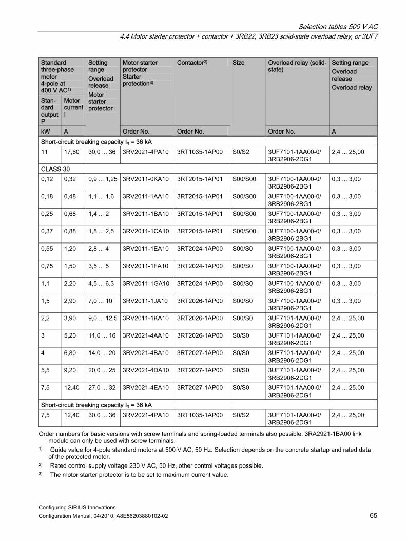
Selection tables 500 V AC 4.4 Motor starter protector + contactor + 3RB22, 3RB23 solid-state overload relay, or 3UF7
Configuring SIRIUS Innovations Configuration Manual, 04/2010, A8E56203880102-02 65
Standard three-phase motor 4-pole at 400 V AC1) Stan-dard output P
Motor current I
Motor starter protector Starter protection3)
Contactor2) Overload relay (solid-state)
Setting range Overload release Overload relay
kW A
Setting range Overload release Motor starter protector
Order No. Order No.
Size
Order No. A Short-circuit breaking capacity Iq = 36 kA 11 17,60 30,0 ... 36 3RV2021-4PA10 3RT1035-1AP00 S0/S2 3UF7101-1AA00-0/
3RB2906-2DG1 2,4 ... 25,00
CLASS 30 0,12 0,32 0,9 ... 1,25 3RV2011-0KA10 3RT2015-1AP01 S00/S00 3UF7100-1AA00-0/
3RB2906-2BG1 0,3 ... 3,00
0,18 0,48 1,1 ... 1,6 3RV2011-1AA10 3RT2015-1AP01 S00/S00 3UF7100-1AA00-0/ 3RB2906-2BG1
0,3 ... 3,00
0,25 0,68 1,4 ... 2 3RV2011-1BA10 3RT2015-1AP01 S00/S00 3UF7100-1AA00-0/ 3RB2906-2BG1
0,3 ... 3,00
0,37 0,88 1,8 ... 2,5 3RV2011-1CA10 3RT2015-1AP01 S00/S00 3UF7100-1AA00-0/ 3RB2906-2BG1
0,3 ... 3,00
0,55 1,20 2,8 ... 4 3RV2011-1EA10 3RT2024-1AP00 S00/S0 3UF7100-1AA00-0/ 3RB2906-2BG1
0,3 ... 3,00
0,75 1,50 3,5 ... 5 3RV2011-1FA10 3RT2024-1AP00 S00/S0 3UF7100-1AA00-0/ 3RB2906-2BG1
0,3 ... 3,00
1,1 2,20 4,5 ... 6,3 3RV2011-1GA10 3RT2024-1AP00 S00/S0 3UF7100-1AA00-0/ 3RB2906-2BG1
0,3 ... 3,00
1,5 2,90 7,0 ... 10 3RV2011-1JA10 3RT2026-1AP00 S00/S0 3UF7100-1AA00-0/ 3RB2906-2BG1
0,3 ... 3,00
2,2 3,90 9,0 ... 12,5 3RV2011-1KA10 3RT2026-1AP00 S00/S0 3UF7101-1AA00-0/ 3RB2906-2DG1
2,4 ... 25,00
3 5,20 11,0 ... 16 3RV2021-4AA10 3RT2026-1AP00 S0/S0 3UF7101-1AA00-0/ 3RB2906-2DG1
2,4 ... 25,00
4 6,80 14,0 ... 20 3RV2021-4BA10 3RT2027-1AP00 S0/S0 3UF7101-1AA00-0/ 3RB2906-2DG1
2,4 ... 25,00
5,5 9,20 20,0 ... 25 3RV2021-4DA10 3RT2027-1AP00 S0/S0 3UF7101-1AA00-0/ 3RB2906-2DG1
2,4 ... 25,00
7,5 12,40 27,0 ... 32 3RV2021-4EA10 3RT2027-1AP00 S0/S0 3UF7101-1AA00-0/ 3RB2906-2DG1
2,4 ... 25,00
Short-circuit breaking capacity Iq = 36 kA 7,5 12,40 30,0 ... 36 3RV2021-4PA10 3RT1035-1AP00 S0/S2 3UF7101-1AA00-0/
3RB2906-2DG1 2,4 ... 25,00
Order numbers for basic versions with screw terminals and spring-loaded terminals also possible. 3RA2921-1BA00 link module can only be used with screw terminals.
1) Guide value for 4-pole standard motors at 500 V AC, 50 Hz. Selection depends on the concrete startup and rated data of the protected motor.
2) Rated control supply voltage 230 V AC, 50 Hz, other control voltages possible. 3) The motor starter protector is to be set to maximum current value.

Selection tables 500 V AC 4.5 Motor starter protector + contactor assembly for star-delta start + 3RU21 thermal overload relay
Configuring SIRIUS Innovations 66 Configuration Manual, 04/2010, A8E56203880102-02
4.5 Motor starter protector + contactor assembly for star-delta start + 3RU21 thermal overload relay
CLASS 5 and CLASS 10, types of coordination 1 and 2, short-circuit breaking capacity Iq = 100 kA
M
Standard three-phase motor 4-pole at 400 V AC1)
Contactors2)
Stan-dard output P
Motor current I
Motor starter protector
Line contactor + delta contactor
Star contactor
Overload relay (thermal)
Setting rangeOverload release Overload relay
kW A Order No. Order No. Order No.
Size
Order No. A Type of coordination 1 5,5 9,2 3RV2311-1JC10 3RT2017-1AP01 3RT2017-1AP01 S00/S00/S00 3RU2116-1GB0 4,5 … 6,3 7,5 12,4 3RV2311-1KC10 3RT2018-1AP01 3RT2017-1AP01 S00/S00/S00 3RU2116-1HB0 5,5 … 8,0 7,5 12,4 3RV2311-1KC10 3RT2024-1AP00 3RT2024-1AP00 S00/S0/S0 3RU2126-1HB0 5,5 … 8,0 11 17,6 3RV2321-4BC10 3RT2026-1AP00 3RT2026-1AP00 S0/S0/S0 3RU2126-1KB0 9,0 … 12,5 11 17,6 3RV2321-4CC10 3RT2026-1AP00 3RT2026-1AP00 S0/S0/S0 3RU2126-1KB0 9,0 … 12,5 15 23 3RV2321-4DC10 3RT2027-1AP00 3RT2027-1AP00 S0/S0/S0 3RU2126-4AB0 11,0 … 16,0 18,5 28 3RV2321-4NC10 3RT2027-1AP00 3RT2027-1AP00 S0/S0/S0 3RU2126-4BB0 14,0 … 20,0 18,5 28 3RV2321-4EC10 3RT2027-1AP00 3RT2027-1AP00 S0/S0/S0 3RU2126-4BB0 14,0 … 20,0 Type of coordination 2 5,5 9,2 3RV2311-1JC10 3RT2026-1AP00 3RT2026-1AP00 S00/S0/S0 3RU2126-1GB0 4,5 … 6,3 7,5 12,4 3RV2311-1KC10 3RT2026-1AP00 3RT2026-1AP00 S00/S0/S0 3RU2126-1HB0 5,5 … 8,0 11 17,6 3RV2321-4BC10 3RT2027-1AP00 3RT2027-1AP00 S0/S0/S0 3RU2126-1KB0 9,0 … 12,5 11 17,6 3RV2321-4CC10 3RT2027-1AP00 3RT2027-1AP00 S0/S0/S0 3RU2126-1KB0 9,0 … 12,5 15 23 3RV2321-4DC10 3RT2027-1AP00 3RT2027-1AP00 S0/S0/S0 3RU2126-4AB0 11,0 … 16,0 18,5 28 3RV2321-4NC10 3RT2027-1AP00 3RT2027-1AP00 S0/S0/S0 3RU2126-4BB0 14,0 … 20,0 18,5 28 3RV2321-4EC10 3RT2027-1AP00 3RT2027-1AP00 S0/S0/S0 3RU2126-4BB0 14,0 … 20,0
Order numbers for basic versions with screw terminals and spring-loaded terminals also possible. 1) Guide value for 4-pole standard motors at 500 V AC, 50 Hz. Selection depends on the concrete startup and rated data
of the protected motor. 2) Rated control supply voltage 230 V AC, 50 Hz, other control voltages possible.

Selection tables 500 V AC 4.6 Motor starter protector + contactor assembly for star-delta start + 3RB22 / 23 / 3 solid-state overload relay, or 3UF7
Configuring SIRIUS Innovations Configuration Manual, 04/2010, A8E56203880102-02 67
4.6 Motor starter protector + contactor assembly for star-delta start + 3RB22 / 23 / 3 solid-state overload relay, or 3UF7
CLASS 5 and CLASS 10, types of coordination 1 and 2, short-circuit breaking capacity Iq = 100 kA
M
Standard three-phase motor 4-pole at 400 V AC1)
Contactors2)
Stan-dard output P
Motor current I
Motor starter protector
Line contactor + delta contactor
Star contactor
Overload relay (solid-state) or current measuring module3)
Setting range Overload release Overload relay
kW A Order No. Order No. Order No.
Size
Order No. A Type of coordination 1 with 3RB22, 3RB23 or 3UF7 5,5 9,2 3RV2311-1JC10 3RT2017-1AP01 3RT2017-1AP01 S00/S00/S00 3UF7101-1AA00-0/
3RB2906-2DG1 2,4 ... 25
7,5 12,4 3RV2311-1KC10 3RT2018-1AP01 3RT2017-1AP01 S00/S00/S00 3UF7101-1AA00-0/3RB2906-2DG1
2,4 ... 25
7,5 12,4 3RV2311-1KC10 3RT2024-1AP00 3RT2024-1AP00 S00/S0/S0 3UF7101-1AA00-0/3RB2906-2DG1
2,4 ... 25
11 17,6 3RV2321-4BC10 3RT2026-1AP00 3RT2026-1AP00 S0/S0/S0 3UF7101-1AA00-0/3RB2906-2DG1
2,4 ... 25
11 17,6 3RV2321-4CC10 3RT2026-1AP00 3RT2026-1AP00 S0/S0/S0 3UF7101-1AA00-0/3RB2906-2DG1
2,4 ... 25
15 23 3RV2321-4DC10 3RT2027-1AP00 3RT2027-1AP00 S0/S0/S0 3UF7101-1AA00-0/3RB2906-2DG1
2,4 ... 25
18,5 28 3RV2321-4NC10 3RT2027-1AP00 3RT2027-1AP00 S0/S0/S0 3UF7102-1AA00-0/3RB2906-2JG1
10 ... 100
18,5 28 3RV2321-4EC10 3RT2027-1AP00 3RT2027-1AP00 S0/S0/S0 3UF7102-1AA00-0/3RB2906-2JG1
10 ... 100
Type of coordination 1 with 3RB3 5,5 9,2 3RV2311-1JC10 3RT2017-1AP01 3RT2017-1AP01 S00/S00/S00 3RB3016-1SB0 3,0 ... 12 7,5 12,4 3RV2311-1KC10 3RT2018-1AP01 3RT2017-1AP01 S00/S00/S00 3RB3016-1SB0 3,0 ... 12 7,5 12,4 3RV2311-1KC10 3RT2024-1AP00 3RT2024-1AP00 S00/S0/S0 3RB3026-1SB0 3,0 ... 12 11 17,6 3RV2321-4BC10 3RT2026-1AP00 3RT2026-1AP00 S0/S0/S0 3RB3026-1QB0 6,0 ... 25 11 17,6 3RV2321-4CC10 3RT2026-1AP00 3RT2026-1AP00 S0/S0/S0 3RB3026-1QB0 6,0 ... 25 15 23 3RV2321-4DC10 3RT2027-1AP00 3RT2027-1AP00 S0/S0/S0 3RB3026-1QB0 6,0 ... 25 18,5 28 3RV2321-4NC10 3RT2027-1AP00 3RT2027-1AP00 S0/S0/S0 3RB3026-1VB0 10 ... 40 18,5 28 3RV2321-4EC10 3RT2027-1AP00 3RT2027-1AP00 S0/S0/S0 3RB3026-1VB0 10 ... 40
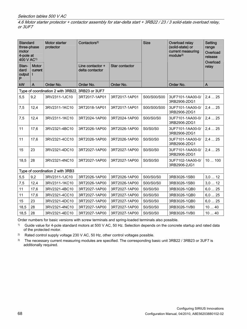
Selection tables 500 V AC 4.6 Motor starter protector + contactor assembly for star-delta start + 3RB22 / 23 / 3 solid-state overload relay, or 3UF7
Configuring SIRIUS Innovations 68 Configuration Manual, 04/2010, A8E56203880102-02
Standard three-phase motor 4-pole at 400 V AC1)
Contactors2)
Stan-dard output P
Motor current I
Motor starter protector
Line contactor + delta contactor
Star contactor
Overload relay (solid-state) or current measuring module3)
Setting range Overload release Overload relay
kW A Order No. Order No. Order No.
Size
Order No. A Type of coordination 2 with 3RB22, 3RB23 or 3UF7 5,5 9,2 3RV2311-1JC10 3RT2017-1AP01 3RT2017-1AP01 S00/S00/S00 3UF7101-1AA00-0/
3RB2906-2DG1 2,4 ... 25
7,5 12,4 3RV2311-1KC10 3RT2018-1AP01 3RT2017-1AP01 S00/S00/S00 3UF7101-1AA00-0/ 3RB2906-2DG1
2,4 ... 25
7,5 12,4 3RV2311-1KC10 3RT2024-1AP00 3RT2024-1AP00 S00/S0/S0 3UF7101-1AA00-0/ 3RB2906-2DG1
2,4 ... 25
11 17,6 3RV2321-4BC10 3RT2026-1AP00 3RT2026-1AP00 S0/S0/S0 3UF7101-1AA00-0/ 3RB2906-2DG1
2,4 ... 25
11 17,6 3RV2321-4CC10 3RT2026-1AP00 3RT2026-1AP00 S0/S0/S0 3UF7101-1AA00-0/ 3RB2906-2DG1
2,4 ... 25
15 23 3RV2321-4DC10 3RT2027-1AP00 3RT2027-1AP00 S0/S0/S0 3UF7101-1AA00-0/ 3RB2906-2DG1
2,4 ... 25
18,5 28 3RV2321-4NC10 3RT2027-1AP00 3RT2027-1AP00 S0/S0/S0 3UF7102-1AA00-0/ 3RB2906-2JG1
10 ... 100
Type of coordination 2 with 3RB3 5,5 9,2 3RV2311-1JC10 3RT2026-1AP00 3RT2026-1AP00 S00/S0/S0 3RB3026-1SB0 3,0 ... 12 7,5 12,4 3RV2311-1KC10 3RT2026-1AP00 3RT2026-1AP00 S00/S0/S0 3RB3026-1SB0 3,0 ... 12 11 17,6 3RV2321-4BC10 3RT2027-1AP00 3RT2027-1AP00 S0/S0/S0 3RB3026-1QB0 6,0 ... 25 11 17,6 3RV2321-4CC10 3RT2027-1AP00 3RT2027-1AP00 S0/S0/S0 3RB3026-1QB0 6,0 ... 25 15 23 3RV2321-4DC10 3RT2027-1AP00 3RT2027-1AP00 S0/S0/S0 3RB3026-1QB0 6,0 ... 25 18,5 28 3RV2321-4NC10 3RT2027-1AP00 3RT2027-1AP00 S0/S0/S0 3RB3026-1VB0 10 ... 40 18,5 28 3RV2321-4EC10 3RT2027-1AP00 3RT2027-1AP00 S0/S0/S0 3RB3026-1VB0 10 ... 40
Order numbers for basic versions with screw terminals and spring-loaded terminals also possible. 1) Guide value for 4-pole standard motors at 500 V AC, 50 Hz. Selection depends on the concrete startup and rated data
of the protected motor. 2) Rated control supply voltage 230 V AC, 50 Hz, other control voltages possible. 3) The necessary current measuring modules are specified. The corresponding basic unit 3RB22 / 3RB23 or 3UF7 is
additionally required.

Selection tables 500 V AC 4.7 Motor starter protector + 3RW40 soft starter
Configuring SIRIUS Innovations Configuration Manual, 04/2010, A8E56203880102-02 69
4.7 Motor starter protector + 3RW40 soft starter
CLASS 10, type of coordination 1, short-circuit breaking capacity Iq = 10 kA
Standard three-phase motor 4-pole at 400 V AC1) Standard output P
Motor current I
Setting range Overload release Motor starter protector
Motor starter protector Motor protection2)
Soft starter
kW A A Order No. Order No.
Size MSP / 3RW40
7,5 15,5 11 ... 16 3RV2011-4AA10 3RW4024-1BB14 S0/S0 11 22 20 ... 25 3RV2021-4DA10 3RW4026-1BB14 S0/S0 15 29 27 ... 32 3RV2021-4EA20 3RW4027-1BB14 S0/S0 18,5 3) 35 34 ... 40 3RV2021-4FA10 3RW4028-1BB14 S0/S0
Order numbers for basic versions with screw terminals and spring-loaded terminals also possible. 3RA2921-1BA00 link module can only be used with screw terminals.
1) Guide value for 4-pole standard motors at 500 V AC, 50 Hz. Selection depends on the concrete startup and rated data of the protected motor.
2) Rated currents taken into account at 40 °C ambient temperature. Rated control supply voltage 230 V AC, 50 Hz, other control voltages possible.
3) Discrete mounting only, without a link module.
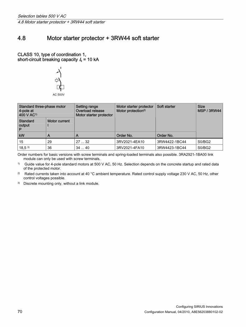
Selection tables 500 V AC 4.8 Motor starter protector + 3RW44 soft starter
Configuring SIRIUS Innovations 70 Configuration Manual, 04/2010, A8E56203880102-02
4.8 Motor starter protector + 3RW44 soft starter
CLASS 10, type of coordination 1, short-circuit breaking capacity Iq = 10 kA
Standard three-phase motor 4-pole at 400 V AC1) Standard output P
Motor current I
Setting range Overload release Motor starter protector
Motor starter protector Motor protection2)
Soft starter
kW A A Order No. Order No.
Size MSP / 3RW44
15 29 27 ... 32 3RV2021-4EA10 3RW4422-1BC44 S0/BG2 18,5 3) 36 34 ... 40 3RV2021-4FA10 3RW4423-1BC44 S0/BG2
Order numbers for basic versions with screw terminals and spring-loaded terminals also possible. 3RA2921-1BA00 link module can only be used with screw terminals.
1) Guide value for 4-pole standard motors at 500 V AC, 50 Hz. Selection depends on the concrete startup and rated data of the protected motor.
2) Rated currents taken into account at 40 °C ambient temperature. Rated control supply voltage 230 V AC, 50 Hz, other control voltages possible.
3) Discrete mounting only, without a link module.

Configuring SIRIUS Innovations Configuration Manual, 04/2010, A8E56203880102-02 71
Fused selection tables up to 690 V 55.1 Contactor short-circuit protection
Short-circuit protection up to 100 kA Type of coordination 1 and 2
Table 5- 1 Fuse links according to IEC 60947 operating class gG, (NH DIAZED, NEOZED; type 3NA, 5SB, 5SE)
Contactor Fuse links1) MLFB P [kW] Type of coordination 12) Type of coordination 22) Size S00 3RT2015-1.. 3 35 20 3RT2016-1.. 4 35 20 3RT2017-1.. 5,5 35 20 3RT2018-1.. 7,5 50 25 Size S0 3RT2024-1.. 5,5 63 25 3RT2025-1.. 7,5 63 25 3RT2026-1.. 11 100 35 3RT2027-1.. 15 125 50 3RT2028-1.. 18,5 125 50
1) Please take account of the operating voltage 2) Assignment and short-circuit protective devices acc. to DIN EN 60947-4-1

Fused selection tables up to 690 V 5.2 Short-circuit protection: Contactor + 3RU2 thermal overload relay, type of coordination 1 and 2
Configuring SIRIUS Innovations 72 Configuration Manual, 04/2010, A8E56203880102-02
5.2 Short-circuit protection: Contactor + 3RU2 thermal overload relay, type of coordination 1 and 2
Short-circuit protection up to 100 kA Type of coordination 1 and 2
Table 5- 2 Fuse links according to IEC 60947 operating class gG, (NH DIAZED, NEOZED; type 3NA, 5SB, 5SE)
Overload relay thermal Contactor Fuse links1) MLFB Setting range MLFB P [kW] Type of coordination
12) Type of coordination 22)
Size S00 3RU2116-0AB0 0,11 ... 0,16 3RT2015-1.. 3 25 0,5 3RU2116-0BB0 0,14 ... 0,20 3RT2015-1.. 3 25 1 3RU2116-0CB0 0,18 ... 0,25 3RT2015-1.. 3 25 1 3RU2116-0DB0 0,22 ... 0,32 3RT2015-1.. 3 25 1,6 3RU2116-0EB0 0,28 ... 0,40 3RT2015-1.. 3 25 2 3RU2116-0FB0 0,35 ... 0,50 3RT2015-1.. 3 25 2 3RU2116-0GB0 0,45 ... 0,63 3RT2015-1.. 3 25 2 3RU2116-0HB0 0,55 ... 0,80 3RT2015-1.. 3 25 4 3RU2116-0JB0 0,70 ... 1,0 3RT2015-1.. 3 25 4 3RU2116-0KB0 0,90 ... 1,25 3RT2015-1.. 3 25 4 3RU2116-1AB0 1,10 ... 1,60 3RT2015-1.. 3 35 6 3RU2116-1BB0 1,4 ... 2,0 3RT2015-1.. 3 35 6 3RU2116-1CB0 1,8 ... 2,5 3RT2015-1.. 3 35 10 3RU2116-1DB0 2,2 -3,2 3RT2015-1.. 3 35 10 3RU2116-1EB0 2,8 ... 4,0 3RT2015-1.. 3 35 16 3RU2116-1FB0 3,5 ... 5,0 3RT2015-1.. 3 35 20 3RU2116-1GB0 4,5 ... 6,3 3RT2015-1.. 3 35 20 3RU2116-1HB0 5,5 ... 8,0 3RT2016-1.. 4 35 20 3RU2116-1JB0 7,0 ... 10 3RT2016-1.. 4 35 20 3RU2116-1KB0 9,0 ... 12,5 3RT2017-1.. 5,5 35 20 3RU2116-4AB0 11 ... 16 3RT2018-1.. 7,5 50 25

Fused selection tables up to 690 V 5.2 Short-circuit protection: Contactor + 3RU2 thermal overload relay, type of coordination 1 and 2
Configuring SIRIUS Innovations Configuration Manual, 04/2010, A8E56203880102-02 73
Overload relay thermal Contactor Fuse links1) MLFB Setting range MLFB P [kW] Type of coordination
12) Type of coordination 22)
Size S0 3RU2126-1CB0 1,8 ... 2,5 3RT2024-1.. 5,5 63 10 3RU2126-1DB0 2,2 -3,2 3RT2024-1.. 5,5 63 10 3RU2126-1EB0 2,8 ... 4,0 3RT2024-1.. 5,5 63 16 3RU2126-1FB0 3,5 ... 5,0 3RT2024-1.. 5,5 63 20 3RU2126-1GB0 4,5 ... 6,3 3RT2024-1.. 5,5 63 20 3RU2126-1HB0 5,5 ... 8,0 3RT2024-1.. 5,5 63 25 3RU2126-1JB0 7,0 ... 10 3RT2024-1.. 5,5 63 25 3RU2126-1KB0 9,0 ... 12,5 3RT2024-1.. 5,5 63 25 3RU2126-4AB0 11 ... 16 3RT2025-1.. 7,5 63 25 3RU2126-4BB0 14 ... 20 3RT2026-1.. 11 100 35 3RU2126-4CB0 17 ... 22 3RT2026-1.. 11 100 35 3RU2126-4DB0 20 ... 25 3RT2026-1.. 11 100 35 3RU2126-4NB0 23 ... 28 3RT2027-1.. 15 125 50 3RU2126-4EB0 27 ... 32 3RT2027-1.. 15 125 50 3RU2126-4PB0 30 ... 36 3RT2028-1.. 18,5 125 50 3RU2126-4FB0 34 ... 40 3RT2028-1.. 18,5 125 50
1) Please take account of the operating voltage 2) Assignment and short-circuit protective devices acc. to DIN EN 60947-4-1

Fused selection tables up to 690 V 5.3 Short-circuit protection: Contactor + 3RB3 solid-state overload relay
Configuring SIRIUS Innovations 74 Configuration Manual, 04/2010, A8E56203880102-02
5.3 Short-circuit protection: Contactor + 3RB3 solid-state overload relay
Short-circuit protection with fuses for motor feeders with 3RB30 and 3RB31, contactor mounting, and stand-alone assembly
Table 5- 3 Derating values for overload relay and contactor size S00
CLASS 5 / 10 20 30
Overload relay
Overload relay Setting range
Contactor
AC-3 derating values MLFB A MLFB kW 400 V 500 V 690 V 400 V 500 V 690 V 400 V 500 V 690 V
Stand-alone assembly
0,4 0,4 0,4 0,4 0,4 0,4 0,4 0,4 0,4 3RB3016-1RB0
0,1 ... 0,4
3RT2015 3,0 0,4 0,4 0,4 0,4 0,4 0,4 0,4 0,4 0,4 Stand-alone assembly
1,3 1,3 1,3 1,3 1,3 1,3 1,3 1,3 1,3 3RB3016-1NB0
0,32 ... 1,25
3RT2015 3,0 1,25 1,25 1,25 1,25 1,25 1,25 1,25 1,25 1,25 Stand-alone assembly
4,0 4,0 4,0 4,0 4,0 4,0 4,0 4,0 4,0
3RT2015 3,0 4,0 4,0 4,0 4,0 4,0 4,0 4,0 4,0 4,0 3RT2016 4,0 4,0 4,0 4,0 4,0 4,0 4,0 4,0 4,0 4,0
3RB3016-1PB0
1 ... 4
3RT2017 5,5 4,0 4,0 4,0 4,0 4,0 4,0 4,0 4,0 4,0 Stand-alone assembly
12,0 12,0 12,0 12,0 12,0 12,0 12,0 12,0 12,0
3RT2016 4,0 9,0 7,7 6,7 9,0 6,5 5,2 9,0 6,5 5,2
3RB3016-1SB0
3 ... 12
3RT2017 5,5 12,0 9,2 6,7 10,0 9,0 6,3 9,0 9,0 6,3 Stand-alone assembly
16,0 16,0 16,0 16,0 16,0 16,0 16,0 16,0 16,0
3RT2017 5,5 12,0 9,2 6,7 10,0 9,0 6,3 9,0 9,0 6,3
3RB3016-1TB0
4 ... 16
3RT2018 7,5 16,0 12,4 8,9 12,9 11,6 8,1 11,6 11,6 8,1

Fused selection tables up to 690 V 5.3 Short-circuit protection: Contactor + 3RB3 solid-state overload relay
Configuring SIRIUS Innovations Configuration Manual, 04/2010, A8E56203880102-02 75
Table 5- 4 Derating values for overload relay and contactor size S0
CLASS 5 / 10 20 30
Overload relay
Overload relaySetting range
Contactor
AC-3 derating values MLFB A MLFB kW 400 V 500 V 690 V 400 V 500 V 690 V 400 V 500 V 690 V
Stand-alone assembly
0,4 0,4 0,4 0,4 0,4 0,4 0,4 0,4 0,4 3RB3026-1RB0
0,1 ... 0,4
3RT2024 5,5 0,4 0,4 0,4 0,4 0,4 0,4 0,4 0,4 0,4 Stand-alone assembly
1,3 1,3 1,3 1,3 1,3 1,3 1,3 1,3 1,3 3RB3026-1NB0
0,32 ... 1,25
3RT2024 5,5 1,25 1,25 1,25 1,25 1,25 1,25 1,25 1,25 1,25 Stand-alone assembly
4,0 4,0 4,0 4,0 4,0 4,0 4,0 4,0 4,0 3RB3026-1PB0
1 ... 4
3RT2024 5,5 4,0 4,0 4,0 4,0 4,0 4,0 4,0 4,0 4,0 Stand-alone assembly
12,0 12,0 12,0 12,0 12,0 12,0 12,0 12,0 12,0
3RT2024 5,5 12,0 12,0 9,0 12,0 12,0 9,0 12,0 12,0 9,0
3RB3026-1SB0
3 ... 12
3RT2025 7,5 12,0 12,0 12,0 12,0 12,0 12,0 12,0 12,0 12,0 Stand-alone assembly
25,0 25,0 25,0 25,0 25,0 25,0 23,0 23,0 23,0
3RT2025 7,5 17,0 17,0 13,0 16,0 16,0 13,0 14,0 14,0 13,0 3RT2026 11,0 25,0 18,0 13,0 16,0 16,0 13,0 14,0 14,0 13,0 3RT2027 15,0 25,0 25,0 21,0 18,6 18,6 15,1 16,2 16,2 15,1
3RB3026-1QB0
6 ... 25
3RT2028 18,5 25,0 25,0 21,0 22,4 22,4 18,2 19,6 19,6 18,2 Stand-alone assembly
40,0 40,0 40,0 28,0 28,0 28,0 23,0 23,0 23,0
3RT2027 15,0 32,0 32,0 21,0 18,6 18,6 15,1 16,2 16,2 15,1
3RB3026-1VB0
10 ... 40
3RT2028 18,5 38,0 32,0 21,0 22,4 22,4 18,2 19,6 19,6 18,2

Fused selection tables up to 690 V 5.3 Short-circuit protection: Contactor + 3RB3 solid-state overload relay
Configuring SIRIUS Innovations 76 Configuration Manual, 04/2010, A8E56203880102-02
Fuse links according to IEC 60947 and UL 508 Short-circuit protection up to 690 V / 100 kA Type of coordination 1 and 2
Table 5- 5 Fuse links for overload relay and contactor size S00
Fuse links1) Acc. to IEC 609473)
Overload relay
Overload relay Setting range
Contactor
Type of coordination2) Acc. to UL 508 4)
(600 V)
Type A Type kW 1 2) Standard short-circuit rating
High short-circuit rating
Stand-alone assembly
35 4 3 3 3RB3016-1RB0
0,1 ... 0,4
3RT2015 3,0 35 4 — — Stand-alone assembly
35 6 6 6 3RB3016-1NB0
0,32 ... 1,25
3RT2015 3,0 35 6 — — Stand-alone assembly
35 20 15 15
3RT2015 3,0 35 20 — — 3RT2016 4,0 35 20 — —
3RB3016-1PB0
1 ... 4
3RT2017 5,5 35 20 — — Stand-alone assembly
50 50 45 45
3RT2016 4,0 35 20 — —
3RB3016-1SB0
3 ... 12
3RT2017 5,5 50 25 — — Stand-alone assembly
50 50 60 60
3RT2017 5,5 50 25 — —
3RB3016-1TB0
4 ... 16
3RT2018 7,5 50 25 — — 1) Take account of the operating voltage 2) Assignment and short-circuit protective devices acc. to DIN EN 60947-4-1 3) NH type 3NA, DIAZED type 5SB, NEOZED type 5SE 4) RK1, RK5, J, CC

Fused selection tables up to 690 V 5.3 Short-circuit protection: Contactor + 3RB3 solid-state overload relay
Configuring SIRIUS Innovations Configuration Manual, 04/2010, A8E56203880102-02 77
Table 5- 6 Fuse links for overload relay and contactor size S0
Fuse links1) Acc. to IEC 609473)
Overload relay
Overload relaySetting range
Contactor
Type of coordination2) Acc. to UL 508 4)
(600 V)
Type A Type kW 1 2 Standard short-circuit rating
High short-circuit rating
Stand-alone assembly
35 4 3 3 3RB3026-1RB0
0,1 ... 0,4
3RT2024 5,5 35 4 — — Stand-alone assembly
35 6 6 6 3RB3026-1NB0
0,32 ... 1,25
3RT2024 5,5 35 6 — — Stand-alone assembly
63 20 15 15 3RB3026-1PB0
1 ...4
3RT2024 5,5 63 20 — — Stand-alone assembly
63 50 45 45
3RT2024 5,5 63 25 — —
3RB3026-1SB0
3 ... 12
3RT2025 7,5 63 25 — — Stand-alone assembly
125 63 100 100
3RT2025 7,5 63 25 — — 3RT2026 11,0 100 35 — — 3RT2027 15,0 125 50 — —
3RB3026-1QB0
6 ... 25
3RT2028 18,5 125 50 — — Stand-alone assembly
125 80 100 100
3RT2027 15,0 125 50 — —
3RB3026-1VB0
10 ... 40
3RT2028 18,5 125 50 — — 1) Take account of the operating voltage 2) Assignment and short-circuit protective devices acc. to DIN EN 60947-4-1 3) NH type 3NA, DIAZED type 5SB, NEOZED type 5SE 4) RK1, RK5, J, CC

Fused selection tables up to 690 V 5.4 Short-circuit protection: Contactor + 3UF7 + 3RB22 / 23 solid-state overload relay
Configuring SIRIUS Innovations 78 Configuration Manual, 04/2010, A8E56203880102-02
5.4 Short-circuit protection: Contactor + 3UF7 + 3RB22 / 23 solid-state overload relay
Short-circuit protection with fuses for motor feeders with 3UF7 and 3RB22/23, contactor mounting, and stand-alone installation
Table 5- 7 Derating values CLASS 5 / 10, 15 and 20
CLASS 5 / 10 15 (3UF7 only) 20
Overload relay
Overload relay Setting range
Contactor
AC-3 derating values
MLFB A MLFB kW 400 V 500 V 690 V 400 V 500 V 690 V 400 V 500 V 690 VSize S00
Stand-alone assembly
3,0 3,0 3,0 3,0 3,0 3,0 3,0 3,0 3,0
3RT2015 3,0 3,0 3,0 3,0 3,0 3,0 3,0 3,0 3,0 3,0 3RT2016 4,0 3,0 3,0 3,0 3,0 3,0 3,0 3,0 3,0 3,0 3RT2017 5,5 3,0 3,0 3,0 3,0 3,0 3,0 3,0 3,0 3,0
3UF7100-1AA00-0/ 3RB2906-2BG1
0,3 ... 3,0
3RT2018 7,5 3,0 3,0 3,0 3,0 3,0 3,0 3,0 3,0 3,0 3RT2015 3,0 7,0 6,0 4,9 7,0 6,0 4,9 7,0 6,0 4,9 3RT2016 4,0 9,0 7,7 6,7 9,0 7,7 6,7 9,0 7,7 6,7 3RT2017 5,5 12,0 9,2 6,7 10,7 9,2 6,7 10,0 9,2 6,7
3UF7101-1AA00-0/ 3RB2906-2DG1
2,4 ... 25
3RT2018 7,5 16,0 12,4 8,9 13,0 12,4 8,9 11,5 11,5 8,9 Size S0
Stand-alone assembly
25 25 25 25 25 25 25 25 25
3RT2024 5,5 12,0 12,0 9,0 12,0 12,0 9,0 12,0 12,0 9,0 3RT2025 7,5 17,0 17,0 13,0 17,0 17,0 13,0 16,0 16,0 13,0 3RT2026 11,0 25,0 18,0 13,0 18,0 18,0 13,0 16,0 16,0 13,0 3RT2027 15,0 25,0 25,0 21,0 23,0 20,0 20,0 20,0 20,0 17,0
3UF7101-1AA00-0/ 3RB2906-2DG1
2,4 ... 25
3RT2028 18,5 25,0 25,0 21,0 23,0 20,0 20,0 20,0 20,0 17,0 Stand-alone assembly
100 100 100 100 100 100 100 100 100
3RT2024 5,5 12,0 12,0 12,0 12,0 12,0 12,0 3RT2025 7,5 17,0 17,0 13,0 17,0 17,0 13,0 16,0 16,0 13,0 3RT2026 11,0 25,0 18,0 13,0 18,0 18,0 13,0 16,0 16,0 13,0 3RT2027 15,0 32,0 32,0 21,0 23,0 20,0 20,0 20,0 20,0 17,0
3UF7102-1AA00-0/ 3RB2906-2JG1
10 ... 100
3RT2028 18,5 38,0 32,0 21,0 23,0 20,0 20,0 20,0 20,0 17,0

Fused selection tables up to 690 V 5.4 Short-circuit protection: Contactor + 3UF7 + 3RB22 / 23 solid-state overload relay
Configuring SIRIUS Innovations Configuration Manual, 04/2010, A8E56203880102-02 79
Table 5- 8 Derating values CLASS 25, 30 and 35
CLASS 25 (3UF7 only) 30 35 (3UF7 only)
Overload relay
Overload relay Setting range
Contactor
AC-3 derating values
MLFB A MLFB kW 400 V 500 V 690 V 400 V 500 V 690 V 400 V 500 V 690 VSize S00
Stand-alone assembly
3,0 3,0 3,0 3,0 3,0 3,0 3,0 3,0 3,0
3RT2015 3,0 3,0 3,0 3,0 3,0 3,0 3,0 3,0 3,0 3,0 3RT2016 4,0 3,0 3,0 3,0 3,0 3,0 3,0 3,0 3,0 3,0 3RT2017 5,5 3,0 3,0 3,0 3,0 3,0 3,0 3,0 3,0 3,0
3UF7100-1AA00-0/ 3RB2906-2BG1
0,3 ... 3,0
3RT2018 7,5 3,0 3,0 3,0 3,0 3,0 3,0 3,0 3,0 3,0 3RT2015 3,0 7,0 6,0 4,9 7,0 6,0 4,9 7,0 6,0 4,9 3RT2016 4,0 9,0 7,7 6,7 9,0 7,7 6,7 8,5 7,7 6,7 3RT2017 5,5 9,5 9,2 6,7 9,0 9,0 6,7 8,5 8,5 6,7
3UF7101-1AA00-0/ 3RB2906-2DG1
2,4 ... 25
3RT2018 7,5 10,3 10,3 8,9 9,5 9,5 8,9 8,8 8,8 8,8 Size S0
Stand-alone assembly
25 25 25 25 25 25 25 25 25
3RT2024 5,5 12,0 12,0 9,0 12,0 12,0 9,0 12,0 12,0 9,0 3RT2025 7,5 14,8 14,8 13,0 14,0 14,0 13,0 13,4 13,4 13,0 3RT2026 11,0 14,8 14,8 13,0 14,0 14,0 13,0 13,4 13,4 13,0 3RT2027 15,0 18,0 18,0 15,0 17,0 17,0 15,0 16,0 16,0 15,0
3UF7101-1AA00-0/ 3RB2906-2DG1
2,4 ... 25
3RT2028 18,5 18,0 18,0 15,0 17,0 17,0 15,0 16,0 16,0 15,0 Stand-alone assembly
100 100 100 100 100 100 100 100 100
3RT2024 5,5 12,0 12,0 — 12,0 12,0 — 12,0 12,0 — 3RT2025 7,5 14,8 14,8 13,0 14,0 14,0 13,0 13,4 13,4 13,0 3RT2026 11,0 14,8 14,8 13,0 14,0 14,0 13,0 13,4 13,4 13,0 3RT2027 15,0 18,0 18,0 15,0 17,0 17,0 15,0 16,0 16,0 15,0
3UF7102-1AA00-0/ 3RB2906-2JG1
10 ... 100
3RT2028 18,5 18,0 18,0 15,0 17,0 17,0 15,0 16,0 16,0 15,0

Fused selection tables up to 690 V 5.4 Short-circuit protection: Contactor + 3UF7 + 3RB22 / 23 solid-state overload relay
Configuring SIRIUS Innovations 80 Configuration Manual, 04/2010, A8E56203880102-02
Table 5- 9 Derating values CLASS 40
CLASS 40 (3UF7 only)
Overload relay Overload relay Setting range
Contactor
AC-3 derating values MLFB A MLFB kW 400 V 500 V 690 V
Size S00 Stand-alone assembly 3,0 3,0 3,0 3RT2015 3,0 3,0 3,0 3,0 3RT2016 4,0 3,0 3,0 3,0 3RT2017 5,5 3,0 3,0 3,0
3UF7100-1AA00-0
0,3 ... 3,0
3RT2018 7,5 3,0 3,0 3,0 3RT2015 3,0 7,0 6,0 4,9 3RT2016 4,0 8,0 7,7 6,7 3RT2017 5,5 8,0 8,0 6,7
3UF7101-1AA00-0
2,4 ... 25
3RT2018 7,5 8,3 8,3 8,3 Size S0
Stand-alone assembly 25 25 25 3RT2024 5,5 12,0 12,0 9,0 3RT2025 7,5 13,0 13,0 13,0 3RT2026 11,0 13,0 13,0 13,0 3RT2027 15,0 15,0 15,0 15,0
3UF7101-1AA00-0
2,4 ... 25
3RT2028 18,5 15,0 15,0 15,0 Stand-alone assembly 100 100 100 3RT2024 5,5 12,0 12,0 — 3RT2025 7,5 13,0 13,0 13,0 3RT2026 11,0 13,0 13,0 13,0 3RT2027 15,0 15,0 15,0 15,0
3UF7102-1AA00-0
10 ... 100
3RT2028 18,5 15,0 15,0 15,0
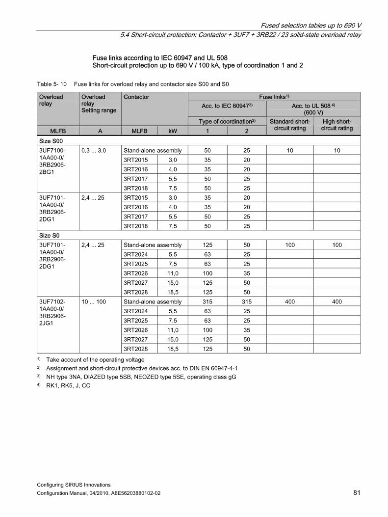
Fused selection tables up to 690 V 5.4 Short-circuit protection: Contactor + 3UF7 + 3RB22 / 23 solid-state overload relay
Configuring SIRIUS Innovations Configuration Manual, 04/2010, A8E56203880102-02 81
Fuse links according to IEC 60947 and UL 508 Short-circuit protection up to 690 V / 100 kA, type of coordination 1 and 2
Table 5- 10 Fuse links for overload relay and contactor size S00 and S0
Fuse links1) Acc. to IEC 609473) Acc. to UL 508 4)
(600 V)
Overload relay
Overload relay Setting range
Contactor
Type of coordination2) MLFB A MLFB kW 1 2
Standard short-circuit rating
High short-circuit rating
Size S00 Stand-alone assembly 50 25 10 10 3RT2015 3,0 35 20 3RT2016 4,0 35 20 3RT2017 5,5 50 25
3UF7100-1AA00-0/ 3RB2906-2BG1
0,3 ... 3,0
3RT2018 7,5 50 25 3RT2015 3,0 35 20 3RT2016 4,0 35 20 3RT2017 5,5 50 25
3UF7101-1AA00-0/ 3RB2906-2DG1
2,4 ... 25
3RT2018 7,5 50 25 Size S0
Stand-alone assembly 125 50 100 100 3RT2024 5,5 63 25 3RT2025 7,5 63 25 3RT2026 11,0 100 35 3RT2027 15,0 125 50
3UF7101-1AA00-0/ 3RB2906-2DG1
2,4 ... 25
3RT2028 18,5 125 50 Stand-alone assembly 315 315 400 400 3RT2024 5,5 63 25 3RT2025 7,5 63 25 3RT2026 11,0 100 35 3RT2027 15,0 125 50
3UF7102-1AA00-0/ 3RB2906-2JG1
10 ... 100
3RT2028 18,5 125 50 1) Take account of the operating voltage 2) Assignment and short-circuit protective devices acc. to DIN EN 60947-4-1 3) NH type 3NA, DIAZED type 5SB, NEOZED type 5SE, operating class gG 4) RK1, RK5, J, CC
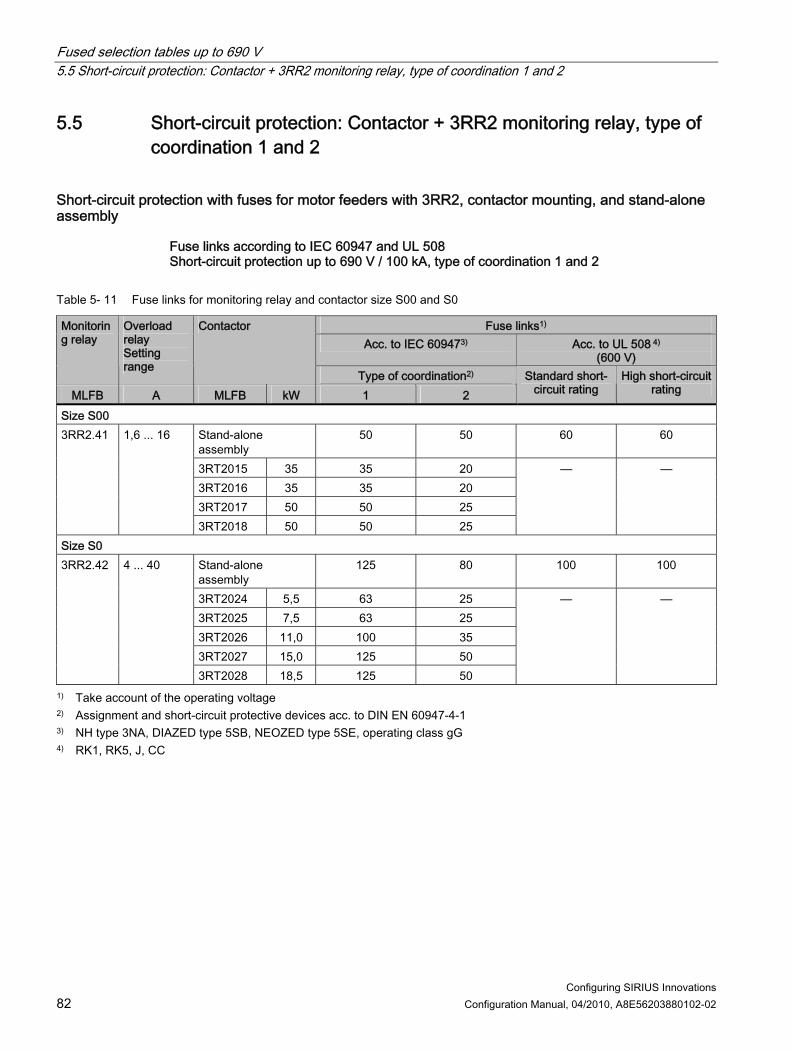
Fused selection tables up to 690 V 5.5 Short-circuit protection: Contactor + 3RR2 monitoring relay, type of coordination 1 and 2
Configuring SIRIUS Innovations 82 Configuration Manual, 04/2010, A8E56203880102-02
5.5 Short-circuit protection: Contactor + 3RR2 monitoring relay, type of coordination 1 and 2
Short-circuit protection with fuses for motor feeders with 3RR2, contactor mounting, and stand-alone assembly
Fuse links according to IEC 60947 and UL 508 Short-circuit protection up to 690 V / 100 kA, type of coordination 1 and 2
Table 5- 11 Fuse links for monitoring relay and contactor size S00 and S0
Fuse links1) Acc. to IEC 609473) Acc. to UL 508 4)
(600 V)
Monitoring relay
Overload relay Setting range
Contactor
Type of coordination2) MLFB A MLFB kW 1 2
Standard short-circuit rating
High short-circuit rating
Size S00 Stand-alone assembly
50 50 60 60
3RT2015 35 35 20 3RT2016 35 35 20 3RT2017 50 50 25
3RR2.41 1,6 ... 16
3RT2018 50 50 25
— —
Size S0 Stand-alone assembly
125 80 100 100
3RT2024 5,5 63 25 3RT2025 7,5 63 25 3RT2026 11,0 100 35 3RT2027 15,0 125 50
3RR2.42 4 ... 40
3RT2028 18,5 125 50
— —
1) Take account of the operating voltage 2) Assignment and short-circuit protective devices acc. to DIN EN 60947-4-1 3) NH type 3NA, DIAZED type 5SB, NEOZED type 5SE, operating class gG 4) RK1, RK5, J, CC
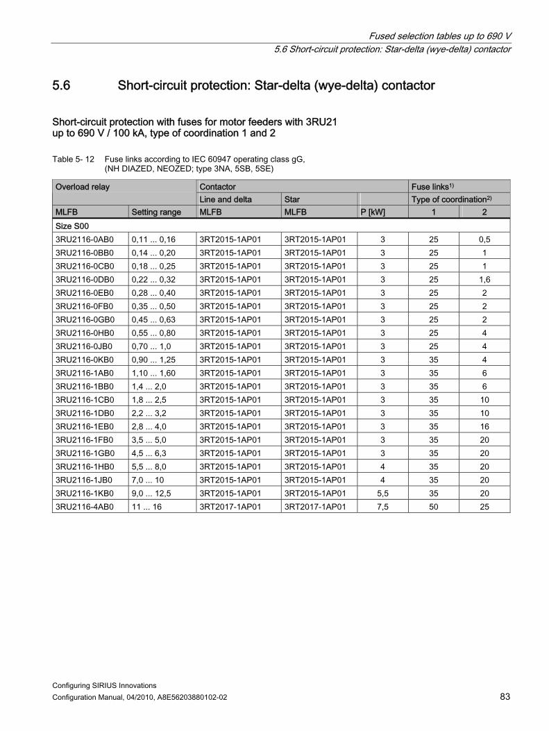
Fused selection tables up to 690 V 5.6 Short-circuit protection: Star-delta (wye-delta) contactor
Configuring SIRIUS Innovations Configuration Manual, 04/2010, A8E56203880102-02 83
5.6 Short-circuit protection: Star-delta (wye-delta) contactor
Short-circuit protection with fuses for motor feeders with 3RU21 up to 690 V / 100 kA, type of coordination 1 and 2
Table 5- 12 Fuse links according to IEC 60947 operating class gG, (NH DIAZED, NEOZED; type 3NA, 5SB, 5SE)
Contactor Fuse links1) Overload relay Line and delta Star Type of coordination2)
MLFB Setting range MLFB MLFB P [kW] 1 2 Size S00 3RU2116-0AB0 0,11 ... 0,16 3RT2015-1AP01 3RT2015-1AP01 3 25 0,5 3RU2116-0BB0 0,14 ... 0,20 3RT2015-1AP01 3RT2015-1AP01 3 25 1 3RU2116-0CB0 0,18 ... 0,25 3RT2015-1AP01 3RT2015-1AP01 3 25 1 3RU2116-0DB0 0,22 ... 0,32 3RT2015-1AP01 3RT2015-1AP01 3 25 1,6 3RU2116-0EB0 0,28 ... 0,40 3RT2015-1AP01 3RT2015-1AP01 3 25 2 3RU2116-0FB0 0,35 ... 0,50 3RT2015-1AP01 3RT2015-1AP01 3 25 2 3RU2116-0GB0 0,45 ... 0,63 3RT2015-1AP01 3RT2015-1AP01 3 25 2 3RU2116-0HB0 0,55 ... 0,80 3RT2015-1AP01 3RT2015-1AP01 3 25 4 3RU2116-0JB0 0,70 ... 1,0 3RT2015-1AP01 3RT2015-1AP01 3 25 4 3RU2116-0KB0 0,90 ... 1,25 3RT2015-1AP01 3RT2015-1AP01 3 35 4 3RU2116-1AB0 1,10 ... 1,60 3RT2015-1AP01 3RT2015-1AP01 3 35 6 3RU2116-1BB0 1,4 ... 2,0 3RT2015-1AP01 3RT2015-1AP01 3 35 6 3RU2116-1CB0 1,8 ... 2,5 3RT2015-1AP01 3RT2015-1AP01 3 35 10 3RU2116-1DB0 2,2 ... 3,2 3RT2015-1AP01 3RT2015-1AP01 3 35 10 3RU2116-1EB0 2,8 ... 4,0 3RT2015-1AP01 3RT2015-1AP01 3 35 16 3RU2116-1FB0 3,5 ... 5,0 3RT2015-1AP01 3RT2015-1AP01 3 35 20 3RU2116-1GB0 4,5 ... 6,3 3RT2015-1AP01 3RT2015-1AP01 3 35 20 3RU2116-1HB0 5,5 ... 8,0 3RT2015-1AP01 3RT2015-1AP01 4 35 20 3RU2116-1JB0 7,0 ... 10 3RT2015-1AP01 3RT2015-1AP01 4 35 20 3RU2116-1KB0 9,0 ... 12,5 3RT2015-1AP01 3RT2015-1AP01 5,5 35 20 3RU2116-4AB0 11 ... 16 3RT2017-1AP01 3RT2017-1AP01 7,5 50 25

Fused selection tables up to 690 V 5.6 Short-circuit protection: Star-delta (wye-delta) contactor
Configuring SIRIUS Innovations 84 Configuration Manual, 04/2010, A8E56203880102-02
Contactor Fuse links1) Overload relay Line and delta Star Type of coordination2)
MLFB Setting range MLFB MLFB P [kW] 1 2 Size S0 3RU2126-1CB0 1,8 ... 2,5 3RT2024-1AP01 3RT2024-1AP01 5,5 63 10 3RU2126-1DB0 2,2 ... 3,2 3RT2024-1AP01 3RT2024-1AP01 5,5 63 10 3RU2126-1EB0 2,8 ... 4,0 3RT2024-1AP01 3RT2024-1AP01 5,5 63 16 3RU2126-1FB0 3,5 ... 5,0 3RT2024-1AP01 3RT2024-1AP01 5,5 63 20 3RU2126-1GB0 4,5 ... 6,3 3RT2024-1AP01 3RT2024-1AP01 5,5 63 20 3RU2126-1HB0 5,5 ... 8,0 3RT2024-1AP01 3RT2024-1AP01 5,5 63 25 3RU2126-1JB0 7,0 ... 10 3RT2024-1AP01 3RT2024-1AP01 5,5 63 25 3RU2126-1KB0 9,0 ... 12,5 3RT2024-1AP01 3RT2024-1AP01 5,5 63 25 3RU2126-4AB0 11 ... 16 3RT2024-1AP01 3RT2024-1AP01 7,5 63 25 3RU2126-4BB0 14 ... 20 3RT2024-1AP01 3RT2024-1AP01 11 100 35 3RU2126-4CB0 17 ... 22 3RT2024-1AP01 3RT2024-1AP01 11 100 35 3RU2126-4DB0 20 ... 25 3RT2024-1AP01 3RT2024-1AP01 11 100 35 3RU2126-4NB0 23 ... 28 3RT2026-1AP01 3RT2024-1AP01 15 125 50 3RU2126-4EB0 27 ... 32 3RT2026-1AP01 3RT2024-1AP01 15 125 50 3RU2126-4PB0 30 ... 36 3RT2026-1AP01 3RT2024-1AP01 18,5 125 50 3RU2126-4FB0 34 ... 40 3RT2026-1AP01 3RT2024-1AP01 18,5 125 50
1) Please take account of the operating voltage 2) Assignment and short-circuit protective devices acc. to DIN EN 60947-4-1

Fused selection tables up to 690 V 5.7 Short-circuit protection: Soft starter + 3RU2 thermal overload relay
Configuring SIRIUS Innovations Configuration Manual, 04/2010, A8E56203880102-02 85
5.7 Short-circuit protection: Soft starter + 3RU2 thermal overload relay
Short-circuit protection with fuses for motor feeders with 3RW30 soft starter and 3RU21 thermal overload relay up to 400 V / 65 kA, type of coordination 1 and 2
Table 5- 13 Fuse links according to IEC 60947 operating class gG, (NH DIAZED, NEOZED; type 3NA, 5SB, 5SE)
Fuse links1) Overload relay Contactor Soft starter Type of coordination2)
MLFB Setting range MLFB kW MLFB kW 1 2 Size S00 3RU2116-1CB0 1,8 ... 2,5 3RT2015-1.. 3 3RW3013 1,5 10 16 3RU2116-1DB0 2,2 ... 3,2 3RT2015-1.. 3 3RW3013 1,5 10 16 3RU2116-1EB0 2,8 ... 4,0 3RT2015-1.. 3 3RW3013 1,5 10 16 3RU2116-1FB0 3,5 ... 5,0 3RT2015-1.. 3 3RW3014 3 16 16 3RU2116-1GB0 4,5 ... 6,3 3RT2015-1.. 3 3RW3014 3 16 16 3RU2116-1HB0 5,5 ... 8,0 3RT2016-1.. 4 3RW3016 4 20 16 3RU2116-1JB0 7,0 ... 10 3RT2016-1.. 4 3RW3016 4 20 16 3RU2116-1KB0 9,0 ... 12,5 3RT2017-1.. 5,5 3RW3017 5,5 25 16 3RU2116-4AB0 11 ... 16 3RT2018-1.. 7,5 3RW3018 7,5 35 20 Size S0 3RU2126-4BB0 14 ... 20 3RT2026-1.. 11 3RW3026 11 63 35 3RU2126-4CB0 17 ... 22 3RT2026-1.. 11 3RW3026 11 63 35 3RU2126-4DB0 20 ... 25 3RT2026-1.. 11 3RW3026 11 63 35 3RU2126-4NB0 23 ... 28 3RT2027-1.. 15 3RW3027 15 80 80 3RU2126-4EB0 27 ... 32 3RT2027-1.. 15 3RW3027 15 80 80 3RU2126-4PB0 30 ... 36 3RT2028-1.. 18,5 3RW3028 18,5 80 80 3RU2126-4FB0 34 ... 40 3RT2028-1.. 18,5 3RW3028 18,5 80 80
1) Please take account of the operating voltage 2) Assignment and short-circuit protective devices acc. to DIN EN 60947-4-1

Fused selection tables up to 690 V 5.8 Short-circuit protection: Solid-state contactor, type of coordination 1 and 2
Configuring SIRIUS Innovations 86 Configuration Manual, 04/2010, A8E56203880102-02
5.8 Short-circuit protection: Solid-state contactor, type of coordination 1 and 2
Short-circuit protection with fuses for 3RF34 solid-state contactor
Fuse links according to IEC 60947 and UL 508 Short-circuit protection up to 600 V / 50 kA, type of coordination 1 and 2
Table 5- 14 Fuse links for monitoring relay and contactor size S00 and S0
Fuse links2) Solid-state contactor Acc. to IEC 609474) Acc. to UL 508 5)
500 V 3NW / 600 V 3NA 50 kA
Type of coordination3)
600 V Standard short-
circuit rating
480 V High short-circuit rating
600 V High short-circuit
rating
MLFB Ie @ 40 °C [A]
P @ 400 V [kW] 1)
1 2 5 kA 65 kA 65 kA 3RF3405-1BB54
5,2 2,2 25 10 25 45
3RF3410-1BB54
9,2 4 40 20 45 45
3RF3412-1BB54
12,5 5,5 40 30 45 50
3RF3416-1BB54
16 7,5 40
On request
30 50 50
Reversing contactors 3RF3403-1BD54
3,8 1,5 25 10 45
3RF3405-1BD54
5,4 2,2 40 10 45
3RF3410-1BD54
7,4 3 40
On request
20 45
—
1) Guide value for 4-pole standard motors at 400 V AC, 50 Hz. Selection depends on the concrete startup and rated data of the protected motor.
2) Take account of the operating voltage 3) Assignment and short-circuit protective devices acc. to DIN EN 60947-4-1 4) NH type 3NA, DIAZED type 5SB, NEOZED type 5SE, operating class gG 5) Class K5, RK5, RK1, J

Fused selection tables up to 690 V 5.9 Short-circuit protection: Motor feeders with 3RW3 + 3RT + 3RB30/3RB31
Configuring SIRIUS Innovations Configuration Manual, 04/2010, A8E56203880102-02 87
5.9 Short-circuit protection: Motor feeders with 3RW3 + 3RT + 3RB30/3RB31
Short-circuit protection with fuses for motor feeders with 3RW30 soft starter and 3RB30 / 3RB31 solid-state overload relay up to 480 V / 65 kA, type of coordination 1 and 2
Table 5- 15 Fuse links according to IEC 60947 operating class gG, (SITOR; type 3NA, 3NE)
Current carrying capacity
Fuse links1) Overload relay Contactor Soft starter
Ie at 400 V and Type of coordination2) MLFB Setting range MLFB kW MLFB kW 40 °C 50 °C 60 °C 1 2 Size S00
3RT2015 3,0 3RW3013 1,5 3,6 3,3 3,0 10 16 3RB3016-1PB0
1 ... 4 3RT2016 4,0 3RW3013 1,5 3,6 3,3 3,0 10 16 3RT2015 3,0 3RW3014 3,0 6,5 6,0 5,5 16 16 3RT2016 4,0 3RW3014 3,0 6,5 6,0 5,5 16 16
3RB3016-1SB0
3 ... 12
3RT2017 5,5 3RW3016 4,0 9,0 8,0 7,0 20 16 3RT2017 5,5 3RW3017 5,5 12,5 12,0 11,0 25 16 3RB3016-
1TB0 4 ... 16
3RT2018 7,5 3RW3018 7,5 16,0 16,0 14,0 35 20 Size S0
3RT2025 7,5 3RW3026 11,0 17,0 17,0 17,0 63 35 3RT2026 11,0 3RW3026 11,0 25,0 23,0 21,0 63 35
3RB3026-1QB0
6 ... 25
3RT2027 15,0 3RW3027 15,0 25,0 25,0 25,0 80 80 3RT2025 7,5 3RW3026 11,0 17,0 17,0 17,0 63 35 3RT2026 11,0 3RW3026 11,0 25,0 23,0 21,0 63 35 3RT2027 15,0 3RW3027 15,0 32,0 29,0 26,0 80 80
3RB3026-1VB0
10 ... 40
3RT2028 18,5 3RW3028 18,5 38,0 34,0 31,0 80 80 1) Please take account of the operating voltage 2) Assignment and short-circuit protective devices acc. to DIN EN 60947-4-1

Fused selection tables up to 690 V 5.10 Contactor assemblies for star-delta (wye-delta) start + 3RB30/31 solid-state overload relay and 3RT20 contactor
Configuring SIRIUS Innovations 88 Configuration Manual, 04/2010, A8E56203880102-02
5.10 Contactor assemblies for star-delta (wye-delta) start + 3RB30/31 solid-state overload relay and 3RT20 contactor
Short-circuit protection with fuses for contactor assemblies for star-delta (wye-delta) start with 3RB30/31 solid-state overload relay and 3RT20 contactor up to 400 V / 65 kA, CLASS 10, type of coordination 1 and 2
Table 5- 16 Fuse links according to IEC 60947 operating class gG, (NH DIAZED, NEOZED; type 3NA, 5SB, 5SE)
Standard three-phase motor 4-pole at 400 V AC2)
Overload relay Line contactor / delta contactor
Star contactor Fuse links1)
Type of coordination2) Standard output kW
Motor current A
MLFB Setting range A
MLFB MLFB 1 2
Size S00 0,75 1,9 1 ... 4 3RT2015-1AP01 3RT2015-1AP01 35 20 1,1 2,7 1 ... 4 3RT2015-1AP01 3RT2015-1AP01 35 20 1,5 3,5 1 ... 4 3RT2015-1AP01 3RT2015-1AP01 35 20 2,2 5 1 ... 4 3RT2015-1AP01 3RT2015-1AP01 35 20 3 6,5
3RB3016-1PB0
1 ... 4 3RT2015-1AP01 3RT2015-1AP01 35 20 4 8,5 3 ... 12 3RT2015-1AP01 3RT2015-1AP01 35 20 5,5 11,5 3 ... 12 3RT2015-1AP01 3RT2015-1AP01 35 20 7,5 15,5
3RB3016-1SB0
3 ... 12 3RT2017-1AP01 3RT2015-1AP01 50 25 11 22 3RB3016-1TB0 4 ... 16 3RT2018-1AP01 3RT2016-1AP01 50 25 Size S0 7,5 15,5 3RB3016-1SB0 3 ... 12 3RT2024-1AP01 3RT2024-1AP01 63 25 11 22 6 ... 25 3RT2024-1AP01 3RT2024-1AP01 63 25 15 29 6 ... 25 3RT2026-1AP01 3RT2024-1AP01 100 35 18,5 35 6 ... 25 3RT2026-1AP01 3RT2024-1AP01 100 35 22 41
3RB3026-1QB0
6 ... 25 3RT2027-1AP01 3RT2026-1AP01 125 50 1) Please take account of the operating voltage 2) Assignment and short-circuit protective devices acc. to DIN EN 60947-4-1

Fused selection tables up to 690 V 5.11 Contactor assemblies for star-delta (wye-delta) start + 3UF7 solid-state overload relay and 3RT20 contactor
Configuring SIRIUS Innovations Configuration Manual, 04/2010, A8E56203880102-02 89
5.11 Contactor assemblies for star-delta (wye-delta) start + 3UF7 solid-state overload relay and 3RT20 contactor
Short-circuit protection with fuses for contactor assemblies for star-delta (wye-delta) start with 3UF7 solid-state overload relay and 3RT20 contactor up to 400 V / 65 kA, CLASS 10, type of coordination 1 and 2
Table 5- 17 Fuse links according to IEC 60947 operating class gG, (NH DIAZED, NEOZED; type 3NA, 5SB, 5SE)
Standard three-phase motor 4-pole at 400 V AC2)
Overload relay Line contactor / delta contactor
Star contactor Fuse links1)
Type of coordination2) Standard output kW
Motor current A
MLFB Setting range A
MLFB MLFB 1 2
Size S00 0,75 1,9 0,3 ... 3 3RT2015-1AP01 3RT2015-1AP01 35 20 1,1 2,7 0,3 ... 3 3RT2015-1AP01 3RT2015-1AP01 35 20 1,5 3,5
3UF7100-1AA00-0/ 3RB2906-2BG1
0,3 ... 3 3RT2015-1AP01 3RT2015-1AP01 35 20 2,2 5 2,4 ... 25 3RT2015-1AP01 3RT2015-1AP01 35 20 3 6,5 2,4 ... 25 3RT2015-1AP01 3RT2015-1AP01 35 20 4 8,5 2,4 ... 25 3RT2015-1AP01 3RT2015-1AP01 35 20 5,5 11,5 2,4 ... 25 3RT2015-1AP01 3RT2015-1AP01 35 20 7,5 15,5 2,4 ... 25 3RT2017-1AP01 3RT2015-1AP01 50 25 11 22
3UF7101-1AA00-0/ 3RB2906-2DG1
2,4 ... 25 3RT2018-1AP01 3RT2016-1AP01 50 25 Size S0 7,5 15,5 2,4 ... 25 3RT2024-1AP01 3RT2024-1AP01 63 25 11 22 2,4 ... 25 3RT2024-1AP01 3RT2024-1AP01 63 25 15 29 2,4 ... 25 3RT2026-1AP01 3RT2024-1AP01 100 35 18,5 35 2,4 ... 25 3RT2026-1AP01 3RT2024-1AP01 100 35 22 41
3UF7101-1AA00-0/ 3RB2906-2DG1
2,4 ... 25 3RT2027-1AP01 3RT2026-1AP01 125 50 1) Please take account of the operating voltage 2) Assignment and short-circuit protective devices acc. to DIN EN 60947-4-1
Note The specified maximum fuse only provides short-circuit protection in the case of fuse values where line overload protection can only be achieved with a larger conductor cross-section than can be connected to the device. When this fuse is used, the line overload protection in accordance with VDE 0100 must be ensured at another point e.g. by means of an overload relay.

Fused selection tables up to 690 V 5.11 Contactor assemblies for star-delta (wye-delta) start + 3UF7 solid-state overload relay and 3RT20 contactor
Configuring SIRIUS Innovations 90 Configuration Manual, 04/2010, A8E56203880102-02

Configuring SIRIUS Innovations Configuration Manual, 04/2010, A8E56203880102-02 91
Installation guidelines 6
The table below provides an overview of the installation guidelines for fuseless load feeders (sizes S00 and S0).
Table 6- 1 Installation guidelines – fuseless load feeders (sizes S00 and S0)
Combination Output
Distance between feeders Permissible installation: h = horizontal, v = vertical
Max. ambient temperature
Vibration and shock1 Motor starter protector and contactor
A mm h, v °C
3RA21 direct starter, screw terminal, DIN rail or wall
≤ 14 0 h, v 60 10 h 60
S00 14 … 16
0 h, v 40
Unlimited
≤ 29 0 h, v 60 10 h 60
S0 29 … 32
0 h, v 40
DIN rail adapter required
3RA21 direct starter, screw terminal, busbar 0 h 40
10 h 60 ≤ 14
10 v 40 10 h 60
S00
14 … 16 10 v 40
Vibration and shock kit 8US1998-1CA10 required
0 h 40 10 h 60
≤ 29
10 v 40 10 h 60
S0
29 … 32 10 v 40
Vibration and shock kit 8US1998-1CA10 required
3RA22 reversing starter, screw terminal, DIN rail or wall ≤ 14 0 h, v 60
10 h 60 S00
14 … 16 0 h, v 40
DIN rail adapter required
≤ 29 0 h, v 60 10 h 60
S0 29 … 32
0 h, v 40
DIN rail adapter required (already included with 3RA22)

Installation guidelines
Configuring SIRIUS Innovations 92 Configuration Manual, 04/2010, A8E56203880102-02
Combination Output
Distance between feeders Permissible installation: h = horizontal, v = vertical
Max. ambient temperature
Vibration and shock1 Motor starter protector and contactor
A mm h, v °C
3RA22 reversing starter, screw terminal, busbar 0 h 60 ≤ 14 0 v 40
10 h 60
S00
14 … 16 10 v 40
Vibration and shock kit 8US1998-1CA10 required
0 h 60 ≤ 29 0 v 40
10 h 60
S0
29 … 32 10 v 40
Vibration and shock kit 8US1998-1CA10 required
3RA21 direct starter, spring-loaded terminal, DIN rail or wall ≤ 14 0 h, v 60
10 h 60 S00
14 … 16 0 h, v 40
Unlimited
≤ 29 0 h, v 60 10 h 60
S0 29 … 32
0 h, v 40
DIN rail adapter required
3RA21 direct starter, spring-loaded terminal, busbar 0 h 40
10 h 60 ≤ 14
10 v 40 10 h 60
S00
14 … 16 10 v 40
Vibration and shock kit 8US1998-1CA10 required
0 h 40 10 h 60
≤ 29
10 v 40 10 h 60
S0
29 … 32 10 v 40
Vibration and shock kit 8US1998-1CA10 required
3RA22 reversing starter, spring-loaded terminal, DIN rail or wall ≤ 14 0 h, v 60
10 h 60 S00
14 … 16 0 h, v 40
DIN rail adapter required
≤ 29 0 h, v 60 10 h 60
S0 29 … 32
0 h, v 40
DIN rail adapter required (already included with 3RA22)

Installation guidelines
Configuring SIRIUS Innovations Configuration Manual, 04/2010, A8E56203880102-02 93
Combination Output
Distance between feeders Permissible installation: h = horizontal, v = vertical
Max. ambient temperature
Vibration and shock1 Motor starter protector and contactor
A mm h, v °C
3RA22 reversing starter, spring-loaded terminal, busbar 0 h 60 ≤ 14 0 v 40
10 h 60
S00
14 … 16 10 v 40
Vibration and shock kit 8US1998-1CA10 required
0 h 60 ≤ 29 0 v 40
10 h 60
S0
29 … 32 10 v 40
Vibration and shock kit 8US1998-1CA10 required
Motor starter protector and soft starter, screw terminal, DIN rail or wall S00 16 2) 2) The feeder must be screwed tight to the top of the motor
starter protector with two screws and fastened to the bottom of the soft starter with a self-locking screw. Not approved for railways, power plants, or shipbuilding.
S0 32 2) 2) The feeder must be screwed tight to the top of the motor starter protector with two screws and fastened to the bottom of the soft starter with a self-locking screw. Not approved for railways, power plants, or shipbuilding.
Motor starter protector and soft starter, spring-loaded terminal, DIN rail or wall S00 16 2) 2) The feeder must be screwed tight to the top of the motor
starter protector with two screws and fastened to the bottom of the soft starter with a self-locking screw. Not approved for railways, power plants, or shipbuilding.
S0 32 2) 2) The feeder must be screwed tight to the top of the motor starter protector with two screws and fastened to the bottom of the soft starter with a self-locking screw. Not approved for railways, power plants, or shipbuilding.
Motor starter protector and solid-state contactor, screw terminal, DIN rail or wall Direct starter 2) 2) Unlimited Not approved for railways, power plants, or
shipbuilding. Reversing starter 2) 2) Unlimited Not approved for railways, power plants, or
shipbuilding. 1) Vibration and shock tests are carried out in accordance with SN 31205 as well as with the relevant standards for railways, shipbuilding, and power plants. 2) Please consult Technical Assistance (www.siemens.com/industrial-controls/technical-assistance).

Installation guidelines
Configuring SIRIUS Innovations 94 Configuration Manual, 04/2010, A8E56203880102-02
Maintain the following distances when mounting the combinations:
Table 6- 2 Installation instructions for 400 V / 500 V AC
Distance from grounded or live parts as well as from cable ducts made of insulating material in accordance with IEC 60947-4 Motor starter protector
Contactor Y mm
X21) mm
Z mm
Rated operating voltage 400 V 3RV2.1 3RT201 20 10 9
3RT201 30 10 9 3RV2.2 3RT2.2 30 10 9
Rated operating voltage 500 V 3RV2.1 3RT201 20 10 9 3RV2.2 3RT202 30 10 20 3RV2.2 + limiter 3RT202 30 10 9
3RV2...
3RT2...
1L1 3L2 5L3
2T1 4T2 6T3
1L1 3L2 5L3
2T1 4T2 6T3
3RV2...
3RT2...
Z
Y
Z
X2
1) Minimum clearance from contactor at the front. In the case of motor starter protectors, no
minimum distance is required at the front.
Note Installation instructions for S0 motor starter protectors from 36 A Minimum cable length between motor starter protector and contactor 150 mm Minimum clearance between motor starter protector and contactor 100 mm
Configuring SIRIUS Innovations Configuration Manual, 04/2010, A8E56203880102-02 95
Service and support 7
Catalogs and information The Siemens Information and Download Center contains all the current catalogs, customer magazines, brochures, demonstration software and promotion packages ready for you to download. Alternatively, you can order them if you prefer (Information (www.siemens.com/industrial-controls/catalogs)).
Newsletter Our regular newsletter gives you the latest information on industrial controls and low-voltage power distribution. You can register at Newsletter (www.siemens.com/industrial-controls/newsletter).
Ordering (e-business) 24/7 access to a comprehensive information and ordering platform for products and systems of the low-voltage controls and distribution portfolio? Comprehensive information on our complete portfolio? Product selection, order tracking, service, support and training information? You can find everything you need to know in the A&D Mall (www.siemens.com/industrial-controls/mall).
Configurators You can find everything on this topic under Configurators (www.siemens.com/industrial-controls/configurators).
Online support More detailed technical information on our low-voltage switchgear and controlgear products and systems, as well as product support, and the service and support we can offer on the basis of helpful support tools is available at Support (www.siemens.com/industrial-controls/support).

Service and support
Configuring SIRIUS Innovations 96 Configuration Manual, 04/2010, A8E56203880102-02
Service (Technical Assistance) Are you looking for the right product to suit your application? Do you have technical questions, require spare parts or need a regional expert on site? We'll help you! Our experienced team of engineers and technicians will be happy to help: ● Speak to them in person from Monday to Friday between 8 a.m. and 5 p.m. (CET) by
phone: +49(911) 895-5900 ● By e-mail: mail to: [email protected]) ● Send them a fax: +49(911) 895-5907 At Technical Assistance (www.siemens.com/industrial-controls/technical-assistance) you can also access the Siemens Automation and Drives Service & Support Internet platform. This facility offers an FAQ database where you can look for information and solutions for your application around the clock. Alternatively, you can send your question direct to a specialist support adviser via the Support Request feature.
Training Our training centers at numerous sites worldwide offer individual training programs covering all fields of automation and individual solutions. Our online courses and various teach-yourself software packages can help you acquire new knowledge in a time and cost-effective manner. You can find everything you need to know about our comprehensive SITRAIN training program online at SITRAIN (www.siemens.com/industrial-controls/training).


www.siemens.com/automation
Subject to change without prior noticeOrder No.: 3ZX1012-0RA21-1AC0 © Siemens AG 2009
Siemens AGIndustry SectorPostfach 48 4890026 NÜRNBERGGERMANY
Service & Support
Download catalogs and information material:www.siemens.com/industrial-controls/catalogs
Newsletter – always up to date: www.siemens.com/industrial-controls/newsletter
E-business in the Industry Mall:www.siemens.com/industrial-controls/mall
Online-Support:www.siemens.com/industrial-controls/support
Contact for all technical information: Technical Assistance Tel.: +49 (911) 895-5900 E-Mail: [email protected] www.siemens.com/industrial-controls/technical-assistance