configuration of cpe 310-s and cpe 311-s transmitters by...
TRANSCRIPT

Configuration of CPE 310-S and CPE 311-Stransmitters by keypad


Table of contents
1. Introduction..........................................................................................................................................51.1. Description of the transmitter.......................................................................................................51.2. Description of the keys.................................................................................................................51.3. Protection tips of the sensor........................................................................................................5
2. Modbus................................................................................................................................................62.1. Configuration of parameters........................................................................................................62.2. Functions......................................................................................................................................62.3. Access code to register................................................................................................................6
3. Access to the different functions.........................................................................................................94. F 100 : Configure the transmitter......................................................................................................10
4.1. Access to the serial number : F100...........................................................................................104.2. Access to the firmware version : F101.......................................................................................104.3. Lock the keypad : F 140............................................................................................................104.4. Modify the safety code : F141....................................................................................................104.5. Configure the Modbus communication (optional)......................................................................11
4.5.1 Set the slave number : F150................................................................................................114.5.2 Set the speed communication : F151..................................................................................11
4.6. Activate the options....................................................................................................................114.7. Back to factory settings : F190..................................................................................................12
5. F 200 : Configuration of the channels and measurement units........................................................135.1. Activate a channel......................................................................................................................135.2. Assign a measurement unit to a channel...................................................................................13
6. F 300 : Manage the analogue outputs..............................................................................................146.1. Set the analogue outputs...........................................................................................................146.2. Set the ranges of the analogue outputs.....................................................................................146.3. Output diagnostic.......................................................................................................................15
6.3.1 Connection configuration.....................................................................................................156.3.2 Perform the output diagnostic.............................................................................................16
7. F400 : Manage the alarms................................................................................................................178. F 500 : Set the pressure measurement............................................................................................20
8.1. Perform an autozero..................................................................................................................208.2. Integration of the pressure measurement..................................................................................208.3. Delay times between 2 autozeros..............................................................................................208.4. Add a coefficient.........................................................................................................................218.5. Add an offset..............................................................................................................................21
9. Functions recap and Modbus connections.......................................................................................229.1. F 100 : configure the transmitter................................................................................................229.2. F 200 : configure the channels and the measurement units.....................................................229.3. F 300 : manage the analogue outputs.......................................................................................229.4. F 400 : manage the alarms........................................................................................................239.5. F 500 : set the measurement.....................................................................................................24


1. Introduction1.1. Description of the transmitter
The CPE 310-S and CPE 311-S can be configured via the keypad. It is possible to set the measurement units, to activate ornot a channel,...
Principle : the different settings are in the form of folders and sub-folders numbers. The digital codes are fully detailed in this manual.
1.2. Description of the keys– Up key : increments a value or a level– Down key : decrements a value or a level– OK key : validates an input– Esc key : cancels the input or goes back to the previous step
1.3. Protection tips of the sensorIt's extremely unwise to remove the protection tip of our hygrometry probes asthe sensitive element is very fragile even to light contacts. However, if youhave to remove the protection tip, take all possible precautions and avoid anycontact with the sensitive element.To remove the protection tip, unscrew it or unclip it.
Introduction 5
Up keyDown key
OK keyEsc key
10 Pa
Channel 1 indicator light Channel 3 indicator light
Channel 2 indicator light
Front access for pressure adjustement
Front access to the mini-Din connector for PC connection
Protection tipto unscrew
Protection tipto unscrew
Sensitiveelement
Sensitiveelement
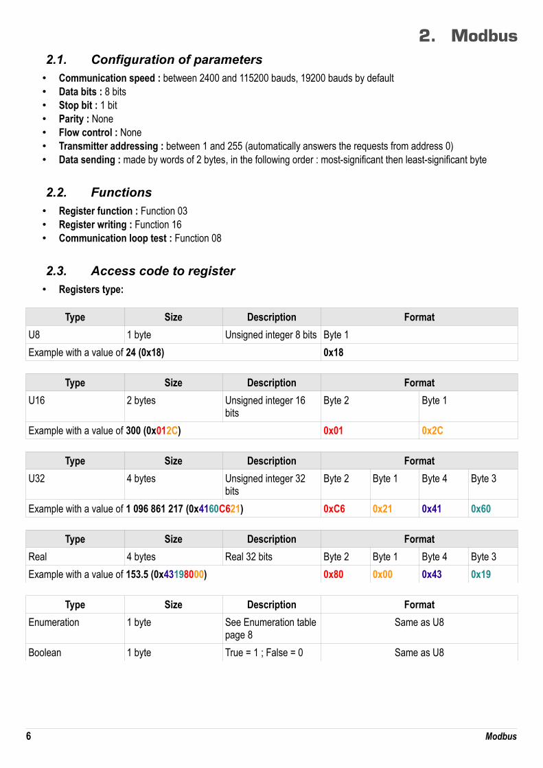
2. Modbus2.1. Configuration of parameters• Communication speed : between 2400 and 115200 bauds, 19200 bauds by default• Data bits : 8 bits• Stop bit : 1 bit• Parity : None• Flow control : None• Transmitter addressing : between 1 and 255 (automatically answers the requests from address 0)• Data sending : made by words of 2 bytes, in the following order : most-significant then least-significant byte
2.2. Functions
• Register function : Function 03• Register writing : Function 16• Communication loop test : Function 08
2.3. Access code to register• Registers type:
Type Size Description Format
U8 1 byte Unsigned integer 8 bits Byte 1
Example with a value of 24 (0x18) 0x18
Type Size Description Format
U16 2 bytes Unsigned integer 16 bits
Byte 2 Byte 1
Example with a value of 300 (0x012C) 0x01 0x2C
Type Size Description Format
U32 4 bytes Unsigned integer 32 bits
Byte 2 Byte 1 Byte 4 Byte 3
Example with a value of 1 096 861 217 (0x4160C621) 0xC6 0x21 0x41 0x60
Type Size Description Format
Real 4 bytes Real 32 bits Byte 2 Byte 1 Byte 4 Byte 3
Example with a value of 153.5 (0x43198000) 0x80 0x00 0x43 0x19
Type Size Description Format
Enumeration 1 byte See Enumeration tablepage 8
Same as U8
Boolean 1 byte True = 1 ; False = 0 Same as U8
6 Modbus

Type Size Description Example
Serial number 8 octets Class (1 byte)Range (1 byte)Year (2 bytes)Month (1 byte)Number (3 bytes)
'3' (0x33)'F' (0x46)13 (0x000D)8 (0x08)98765 (0x0181CD)
Format
Byte 2 (range) Byte1 (class) Byte 4 (year) Byte 3 (year)
Byte 6 (number)
Byte 5 (month)
Byte 8 (number)
Byte 7 (number)
0x46 0x33 0x00 0x0D 0xCD 0x08 0x01 0x81
Example with 3F13898765 : 0x0181CD08000D4633
Alarms and relays status – Modbus code : 7000Encoded on 4 octets (U32)
Byte 2 Byte 1
b8 – b15 b7 – b4 b3 b2 b1 b0
Unused UnusedUnused Channel 3 Channel 2 Channel 1
Alarm state*
(*)1 : the channel is in alarm state / 0 : the channel is not in alarm state
Byte 4 Byte 3
b31 – b28 b27 b26 b25 b24 b23 – b20 b19 b18 b17 b16
Unused Relay 4** Relay 3** Relay 2** Relay 1** Unused Unused Alarm 3*** Alarm 2*** Alarm 1***
(**)1 : the alarm is activated / 0 : the alarm is deactivated(***)1 : the relay is triggered / 0 : the relay is not triggered
• Values – Modbus code : 7010 (channel 1)7040 (channel 2)7070 (channel 3)
• Number of digits after the decimal point – Modbus code : 7020 (channel 1)7050 (channel 2)7080 (channel 3)
• Unit – Modbus code : 7030 (channel 1)7060 (channel 2)7090 (channel 3)
List of units :
Field Unit Value
None 0
Temperature°C 16
°F 17
Hygrometry %HR 32
g/Kg 33
Modbus 7

Kj/KG 34
°C td 35
°F td 36
°C Tw 37
°F Tw 38
Pressure
kPa 50
inWg 51
hPa 52
mbar 53
mmHg 54
mmH2O 55
daPa 56
Pa 57
Air velocity
m/s 64
fpm 65
km/h 66
Combustion ppm 112
“Enumerations” table :
Corresponding values 0 1 2 3 4 5 6 7
Modbus Com speed 2400 4800 9600 19200 38400 115200 UnusedChannel x Unit See list of unitChannel x Transmitter none probe 1 probe 2 module UnusedOutput x Type 4 - 20 mA 0 - 20 mA 0 - 10 V 0 - 5 V 0 - 1 V UnusedOutput x Diagnostic Deactivate 0% 50% 100% Unused
Alarm x Mode Deactivate Rising edge Falling edge MonitoringTransmitter state
Unused
Alarm x Security Negative Positive UnusedRelay x Selection OFF ON Alarm 1 Alarm 2 Alarm 3 Unused
8 Modbus

3. Access to the different functions
This step is compulsory for each configuration.
First, to access to the transmitter functions, and for safety, a safety code must be entered. The default safety code is 0101.• The transmitter must be energized.
➢ Connect the transmitter.➢ Wait until the initializing period is over.➢ Press OK.
“Code” is displayed with “0000”. The 1st 0 blinks.➢ Press OK to go to the 2nd 0.
It blinks.➢ Press Up key to display 1 then press OK.
The 3rd 0 blinks.➢ Press OK to go to the 4th 0.➢ Press Up key to display 1 then press OK.
The following screen is displayed :
“F 100” is for the number of the configuration folder. There are 5 folders : • F 100 : folder of the transmitter configuration. See page 10.• F 200 : folder of the channels and measurement units. Seer page 13.• F 300 : folder of the analogue outputs. See page 14.• F 400 : folder of the alarms. See page 17.• F 500 : folder of the channels, integration and autozero configuration. See page 20.
To select the required folder : “F 100” is displayed and 1 is blinking.
➢ Press Up key until the number of the required folder is displayed (F 100, F 200, F 300 or F 500).➢ Press OK.
9 Access to the different functions
Code
0101
F 100

4. F 100 : Configure the transmitterThis folder allows to configure the following parameters of the transmitter : safety code, modbus, options and factory configuration.It also indicates the serial number and the firmware version of the transmitter.
4.1. Access to the serial number : F100The serial number allows to get activation codes for the options.
F 100 is displayed (see previous page).➢ Press OK.
“F 100” is displayed with the serial number of the transmitter that scrolls below.
4.2. Access to the firmware version : F101F100 folder is displayed.
➢ Press Up key.“F 101” is displayed with the version number that scrolls below (e.g : 1.00)
4.3. Lock the keypad : F 140For more safety and to avoid any handling mistake, it is possible to lock the keys.
F101 sub-folder is displayed.➢ Press Up key.
“F 140” is displayed with “0” indicating that the locking is on.➢ Press OK.
“0” blinks.➢ Press Up or Down key, “1” blinks, then press OK.
“LOCK” is displayed for a few seconds then the transmitter backs to the displaying of measured values.All the keys are inactive. To activate them again :
➢ Press OK for 10 seconds.“LOCK” is displayed for a few seconds then the transmitter goes back to the displaying of measured values and keys are active again.
4.4. Modify the safety code : F141It is possible to modify the safety code.
F140 sub-folder is displayed.➢ Press Up key.
“F 141” is displayed with the safety code below.➢ Press OK.
The 1st zero blinks.➢ Press Up or Down key to modify the digit then press OK.
The 2nd digit blinks.➢ Press Up or Down key to modify the digit then press OK.
The 3rd digit blinks.➢ Press Up or Down key to modify the digit then press OK.
The 4th digit blinks.➢ Press Up or Down key to modify the digit then press OK.
“OK”» is displayed.➢ Press OK to validate the modification of the code or Esc to cancel.
The transmitter goes back to the displaying of the F141 folder with the new code indicated below.
F 100 : Configure the transmitter 10

4.5. Configure the Modbus communication (optional)
Modbus option must be activated (see chapter 4.6).
4.5.1 Set the slave number : F150
F141 sub-folder is displayed.➢ Press Up key.
“F 150” is displayed.➢ Press OK.
“F150” blinks with the serial number below (e.g : 255).➢ Press OK.
The 1st digit of the slave number blinks.➢ Press Up and Down keys to modify it then press OK.
The 2nd digit of the slave number blinks.➢ Press Up and Down keys to modify it then press OK.
The 3rd digit of the slave number blinks.➢ Press Up and Down keys to modify it then press OK.
“F150” blinks with the selected slave number below.
4.5.2 Set the speed communication : F151
➢ Press Up or Down key to go to F151 sub-folder.Speed communication in bits per second is displayed (e.g : 9600).
➢ Press OK.The speed communication blinks.
➢ Press Up and Down keys to select the required speed communication between the following values : • 2400 bds• 4800 bds• 9600 bds• 19.2 Kbds • 38.4 Kbds• 115.2 Kbds
➢ Press OK.“F151” blinks with the selected speed communication below.
4.6. Activate the options
To activate an option, an activation code is necessary. This code is provided by the manufacturer.Available options for CPE310 are the high resolution in pressure (F170 sub-folder) (only for CPE 310-S) and Modbus (F171 sub-folder).
- High resolution in pressure option : F170“F150" sub-folder is displayed.
➢ Press Up key.“F170” blinks and “0” is displayed below, meaning the option is not activated.
➢ Press OK.“0” blinks.
➢ Press Up key.The transmitter asks for an activation code.
➢ Enter the activation code (same procedure as for the safety code) then press OK.“F170” blinks and “1” is displayed below, meaning the option is activated.
11 F 100 : Configure the transmitter
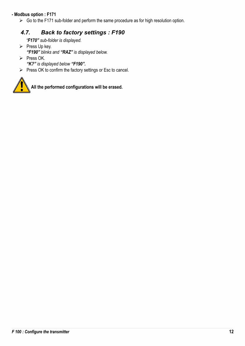
- Modbus option : F171➢ Go to the F171 sub-folder and perform the same procedure as for high resolution option.
4.7. Back to factory settings : F190“F170” sub-folder is displayed.
➢ Press Up key.“F190” blinks and “RAZ” is displayed below.
➢ Press OK.“K?” is displayed below “F190”.
➢ Press OK to confirm the factory settings or Esc to cancel.
All the performed configurations will be erased.
F 100 : Configure the transmitter 12

5. F 200 : Configuration of the channels andmeasurement units
This folder allows to activate the channels and to set measurement unit for each channel.
5.1. Activate a channelThe transmitter is powered on.
➢ Press OK.➢ Enter the activation code (see page 9).➢ Press OK.➢ Press Up key to go to F200 folder.➢ Press twice OK.
“SDE” is displayed below “F200”.➢ Press OK.
“SDE” for probe or “OFF” for deactivated channel or “PRES” for pressure blinks.➢ Press Up and Down key to select :
• « SDE » : channel is activated with a measurement probe• « PRES » : channel is activated with a pressure board• « OFF » : channel is deactivated
➢ Press OK.The last zero of F200 blinks.
“F200” folder allows to activate the channel 1 of the transmitter.To activate channels 2 and 3 go to the following folders :
• F210 for channel 2• F220 for channel 3➢ Perform the same procedure as for the channel 1.
5.2. Assign a measurement unit to a channelThe transmitter is powered on and a channel is activated.“F200” folder is displayed.
➢ Press Up key.“F201” sub-folder is displayed with the unit corresponding to the channel 1 below.
➢ Press OK.The unit blinks.
➢ Press Up and Down keys to select the required unit.➢ Press OK.
“---” sign means that the channel is deactivated.
“F201” sub-folder allows to select the unit for the channel 1.To select the unit for channels 2 and 3, go to the following folders :
• F211 for channel 2• F221 for channel 3➢ Perform the same procedure as for the unit selection for the channel 1.
13 F 200 : Configuration of the channels and measurement units

6. F 300 : Manage the analogue outputs6.1. Set the analogue outputs
The transmitter is powered on.➢ Press OK.➢ Enter the activation code (see page 9).➢ Press OK.➢ Press Up key to go to F 300 folder corresponding to the analogue output of the channel 1 then press twice OK.
“F300is displayed with the analogue output below.➢ Press OK.
The analogue output blinks.➢ Press Up or Down key to select the required output signal :
• 4-20 mA• 0-20 mA• 0-10 V• 0-5 V
➢ Press OK.
“F300” folder is for the analogue output of the channel 1.For the channels 2 and 3, go to the following folders :
• F310 for the channel 2• F320 for the channel 3➢ Perform the same procedure as for the channel 1.
6.2. Set the ranges of the analogue outputsThis function allows to modify the ranges of the analogue outputs.
Values to enter depend on the unit of measurement and not on the measurement range of the transmitter.
Ex : on a CPE 310-S pressure transmitter (0 to ±100 Pa) with a reading in mmH2O, the minimum and maximum ranges must be configured on a measuring range from 0 to ±10 mmH2O. See conversion chart page 16.
The transmitter is powered on.➢ Press OK.➢ Enter the activation code (see page 9).➢ Press OK.➢ Press Up key to go to F301 folder corresponding to the minimum range of the channel 1.➢ Press OK.
The 1st digit of the minimum range blinks.➢ Enter with Up and Down keys the figure value or the negative sign of the value then press OK.
The 2nd digit blinks.➢ Enter with Up and Down keys its value then press OK.➢ Perform the same procedure for the following figures.➢ Press OK when the last figure is configured.
F 301 blinks, the minimum range is configured.
➢ Press Up key then press OK to enter in the folder F 302 corresponding to the high range of the channel 1.The 1st digit of the high range blinks.
➢ Enter with Up and Down keys the figure value or the negative sign of the value then press OK.The 2nd digit blinks.
F 300 : Manage the analogue outputs 14

➢ Enter with Up and Down keys its value then press OK.➢ Perform the same procedure for the following figures.➢ Press OK when the last figure is configured.
F 302 blinks, the high range is configured.
To set the low and high ranges of the channel 2, go to the folder F311 (low range) and F 312 (high range) and follow the setting procedure of the channel 1.To set the low and high ranges of the channel 3, go to the folder F 321 (low range) and F 322 (high range) and follow the setting procedure of the channel 1.
6.3. Output diagnostic
This function allows to check on a measurement device (multimeter, regulator or automate) the proper functioning of the outputs. The transmitter will generate a voltage (between 0 and 10 V) or a current (between 0 and 20 mA) according to the setting of the type of output.
• For a 0-10 V output signal, the transmitter will generate 0 – 5 or 10 V.• For a 0-5 V output signal, the transmitter will generate 0 – 2.5 or 5 V.• For a 4-20 mA output signal, the transmitter will generate 4 – 12 or 20 mA.
6.3.1 Connection configuration
Before carrying out the output diagnostics, all connections and configurations of the transmitter must be enabled, to avoid any damage on the transmitter and the multimeter !
➢ Select an output for the output diagnostic.OUT1, OUT2 or OUT3 indicated on the connection label.
➢ Connect a measurement device on the channel 1, 2 or 3.
15 F 300 : Manage the analogue outputs
Connection of the 0/4-20 mA current output : Connection of the 0/4-20 mA voltage output :
multimeter-
GND
-
mA
+
1 2 3
+
VOUT1
multimeter
7 8 9
OUT3
4 5 6
multimeter
OUT2
7 8 9
OUT3
4 5 61 2 3
multimeter
OUT1
multimeter
+- +
multimeter
-
GNDmA V GNDmA V GNDmA V GNDmA V GNDmA VOUT2
--+
+ --+
++
- +-+
- +-

6.3.2 Perform the output diagnostic
Once the connection to the measurement device is performed, you can carry out the analogue output diagnostics on several check points.
The transmitter is powered on.➢ Press OK.➢ Enter the activation code (see page 9).➢ Press OK.➢ Press Up key to go to F303 folder.➢ Press OK.
F 303 blinks, corresponding to the folder of the channel 1 diagnostic.➢ Press OK.➢ Press Up and Down keys to select the signal the transmitter must generate.
Display Generated output Example
1/3 Simulates 0 % of the output range On the range 0-10V, the transmitter will generate 0 V.
2/3 Simulates 50 % of the output range On the range 0-10V, the transmitter will generate 5 V.
3/3 Simulates 100 % of the output range On the range 0-10V, the transmitter will generate 10 V.
If the deviations are too large (>0,05V or >0,05mA) between the signal issued and the value displayed on the multimeter, we recommend that you return the transmitter to our factory.
For the diagnostic of the channel 2, go to F 313 folder and perform the same procedure as for the channel 1.For the diagnostic of the channel 3, go to F 323 folder and perform the same procedure as for the channel 1.
Measurement conversion charts :
• PressurePa mmH2O InWG mbar mmHG kPa daPa hPa
±100 ±10.2 ±0.40 ±1.00 ±0.75 ±0.100 ±10.0 ±1.00
±1000 ±102.0 ±4.01 ±10.00 ±7.50 ±1.000 ±100.0 ±10.00
• Temperature°C °F
From 0.0 to +50.0 From +32.0 to +122.0
From -20.0 to +80.0 From -4.0 to +176.0
From -40.0 to +180.0 From -40.0 to +356.0
From -100.0 to +400.0 From -148.0 to +752.0
F 300 : Manage the analogue outputs 16

7. F400 : Manage the alarms
Three alarm modes are available : • Rising edge (1 threshold) : the alarm goes off when the measurement exceeds the threshold and stops when it is
below the threshold• Falling edge (1 threshold) : the alarm goes off when the measurement is below the threshold and stops when it
exceeds the threshold.• Monitoring (2 thresholds) : the alarm goes off when the measurement is outside the defined low and high
thresholds.
When an alarm goes off, it is possible to acknowledge it pressing OK key on the transmitter : the audible alarm, if it is activated, turns off and the displayed value blinks during the acknowledgement duration (from 0 to 60 minutes). At the end of the acknowledgement duration, if the transmitter is still in alarm state, the audible alarm is reactivated.
It is possible to set 3 different alarms : • F400 folder corresponds to the alarm 1 setting• F410 folder corresponds to the alarm 2 setting• F420 folder corresponds to the alarm 3 setting
The alarm setting procedure explained below corresponds to the alarm 1 setting. For the alarms 2 and 3 settings, go to the corresponding folder and perform the same procedure as for the alarm 1.
The transmitter is powered on.➢ Press OK.➢ Enter the activation code (see page 9).➢ Press OK.➢ Press Up key to go to F 400 folder then press twice OK.
This folder is about the alarm mode.➢ Press Up or Down key to select the required alarm mode :
17 F400 : Manage the alarms
Rising edge Falling edge
Measurement (m) > Threshold (S) during the time-delay T1 → Alarm activationMeasurement (m) < Threshold (S) - Hysteresis (H) during the time-delay T2 → Alarm deactivation
Measurement (m) < Threshold (S) during time-delay T1 → Alarm activation.Measurement (m) > Threshold (S) + Hysteresis (H) during time-delay T2 → Alarm deactivation
Monitoring
The alarm goes off when the measurement is outside the low and high thresholds.

• OFF : alarm is deactivated• 1/3 : rising edge mode• 2/3 : falling edge mode• 3/3 : monitoring mode
➢ Press OK.“F400” blinks.
➢ Press Up key to go to the F401 folder of the alarm 1 (F411 for alarm 2 and F421 for alarm 3) then press OK.➢ Press Up or Down key then select the channel where the alarm will be activated.➢ Press OK.
“F401” blinks.➢ Press Up key to go to F402 folder (F412 for alarm 2 and F422 for alarm 3) then press OK.
This folder is about the threshold 1 setting.➢ Set the threshold 1 with Up and Down keys.➢ Press OK when the last digit is set.
“F402” blinks.➢ Press Up key to go F403 folder (F413 for alarm 2 and F423 for alarm 3) then press OK.
This folder is about : • For a rising or falling edge : hysteresis setting• For a monitoring : threshold 2 setting.
➢ Set the hysteresis or the threshold 2 with Up and Down keys.➢ Press OK when the last digit has been set.
“F403” blinks.➢ Press Up key to go to F404 folder (F414 for alarm 2 and F424 for alarm 3) then press OK.
This folder is about the delay time 1 setting.➢ Set the delay time 1 with Up and Down keys.➢ Press OK when the last digit has been set.
“F404” blinks.➢ Press Up key to go to F405 folder (F415 for alarm 2 and F425 for alarm 3) then press OK..
This folder is about the delay time 2 setting.➢ Set the delay time 2 with Up and Down keys.➢ Press OK when the last digit has been set.
“F405” blinks.➢ Press Up key to go to F406 folder (F416 for alarm 2 and F426 for alarm 3) then press OK..
This folder allows to activate or not the audible alarm.➢ Set the activation of the audible alarm with Up and Down keys :
• 1 : audible alarm is activated• 2 : audible alarm is deactivated
➢ Press OK to validate the alarm..“F406” blinks.
➢ Press Up key to to th F407 folder (F417 for alarm 2 and F427 for alarm 3) then press OK.This folder is about the acknowledgement of the alarm.
➢ Set the acknowledgement duration of the alarm with Up and Down keys.➢ Press OK when the last digit has been set.
F400 : Manage the alarms 18

F 408 : Alarm latching modeThe latching mode is when the transmitter goes into alarms, it starts beeping and when it goes out of alarm (normal) it should continue beeping until an operator acknowledges it.
➢ Go to F408 folder (F418 for the alarm 2 and F428 for the alarm 3) then press OK.➢ Select ON to activate the alarm latching or OFF to deactivate it.➢ Press OK.
19 F400 : Manage the alarms
Delay-time : 10 min
Acknowledgement
Alarm ON
Alarm OFF
Acknowledgement Acknowledgement
LED ON
LED OFF
Latching ON
m
t
Threshold 1
Threshold 2
Acknowledgement
Alarm ON
Alarm OFF
Delay-time : 10 min
Acknowledgement
LED ON
LED OFF
Latching OFF
m
t
Threshold 1
Threshold 2

8. F 500 : Set the pressure measurementThis part allows to set an integration coefficient, to perform an autozero, to set a delay time between two autozeros.In order to compensate a possible drift of the sensor, it is possible to add an offset and/or a coefficient to the value displayed by the transmitter.
8.1. Perform an autozeroCPE 310-S and CPE 311-S transmitters have a manual autozero which guarantees a good reliability of the measurement inhigh and low ranges.The autozero compensates for any long-term drifts of the sensitive element, with the manual adjusting of the zero.To perform a self-calibration :
➢ Press Esc during 8 seconds.
8.2. Integration of the pressure measurementThe pressure measurement element is very sensitive and reacts to pressure changes. When making measurements in unstable air movement conditions, the pressure measurement may fluctuate. The integration coefficient (from 0 to 9) makesan average of the measurements ; this helps to avoid any excessive variations and guarantees a stable measurement.New displayed value = [((10 - Coef.) x New Value) + (Coef. x Old value)] /10Example : CPE 311-S (0-1000 Pa) – Current measurement : 120 Pa – New measurement : 125 PaThe pressure source being stable, the user selects a low integration. Integration : 1, maximum admitted variation ±10 Pa. The variation is lower than 10 Pa, it is possible to apply the integration calculation formula.Next displayed value : ((9 * 125) + (1 *120 ))/10 = 124.5 i.e, 124 Pa. If the new measurement had been de 131 Pa, the next displayed value would have been 100% of the new value i.e, 131 Pa.
The transmitter is powered on.➢ Press OK.➢ Enter the activation code (see page 9).➢ Press OK.➢ Press Up key to go to F500 folder.➢ Press OK.➢ Set the integration value with Up and Down keys.
This value is between 0 and 9 with : • Coefficient 0 : no integration, important fluctuation of the displayed value• Coefficient 9 : maximum integration, more stable measurement display.
8.3. Delay times between 2 autozerosIt is possible to set an interval between two self-calibrations.
The transmitter is powered on.➢ Press OK.➢ Enter the activation code (see page 9).➢ Press OK.➢ Press Up key to go to F500 folder.➢ Press OK.➢ Press Up key to go to F510 folder.➢ Press OK.
The duration between 2 self-calibrations is displayed.➢ Set the duration with Up and Down keys.
This delay time must be between OFF (no self-calibration) and 60 minutes.➢ Press OK to validate the duration.
20 F 500 : Set the pressure measurement

8.4. Add a coefficientThe correction coefficient allows to adjust the transmitter according to data in pressure of the installation.How to calculate it ? For example, the pressure in your section is 20 Pa and the transmitter displays 18 Pa. The coefficientto apply is 20 / 18, it means 1.111.
The transmitter is powered on.➢ Press OK.➢ Enter the activation code (see page 9).➢ Press OK.➢ Press Up key to go to F500 folder.➢ Press OK.➢ Press Up key to go to F520 folder then press OK.
“F 520” blinks corresponding to the folder of the gain setting for the channel 1.➢ Press OK.
The 1st digit of the gain blinks.➢ Enter with Up and Down keys the figure value or the negative sign of the value then press OK.
The 2nd digit blinks.➢ Enter with Up and Down keys its value then press OK.➢ Perform the same procedure for the following figures.➢ Press OK when the last digit has been set.
F 520 blinks, the coefficient for the channel 1 is set.
To add a gain to the channel 2, go to F 530 folder and perform the same procedure as for the channel 1.To add a gain to the channel 3, go to F 540 folder and perform the same procedure as for the channel 1.
8.5. Add an offsetIn order to compensate any possible drift of the sensor, it is possible to add an offset to the value displayed by the transmitter entering a digital value via the keypad.
The transmitter is powered on.➢ Press OK.➢ Enter the activation code (see page 9).➢ Press OK.➢ Press Up key to go to F500 folder.➢ Press OK.➢ Press Up key to go to F 521 folder then press OK.
“F 521” blinks, corresponding to the folder of the offset setting for the channel 1.➢ Press OK.
The 1st digit of the offset blinks.➢ Enter with Up and Down keys the figure value or the negative sign of the value then press OK.
The 2nd digit blinks.➢ Enter with Up and Down keys its value then press OK.➢ Perform the same procedure for the following figures.➢ Press OK when the last digit has been set.
F 521 blinks, the offset for the channel 1 is set.
To add an offset to the channel 2, go to F 531 folder and perform the same procedure as for the channel 1.To add an offset to the channel 3, go to F 541 folder and perform the same procedure as for the channel 1.
F 500 : Set the pressure measurement 21

9. Functions recap and Modbus connections9.1. F 100 : configure the transmitter
Code Register type Modbus Description Possibilities
F 100 Real 1000 Serial number of the transmitter
F 101 - 1010 Firmware version
- U32 1020 Transmitter ID
- U32 1030 Probe ID
F 135 Boolean 1350 Sound
F 140 Boolean 1400 Keypad locking 0 : deactivated1 : activated
F 141 U16 1410 Safety code
F 150 U8 1500 Modbus slave number From 1 to 255
F 151 Enumeration 1510 Modbus communication speed
2400 / 4800 / 9600/ 19200 / 38400 / 115200 bds
F 170 U32 1700 Activation of the high resolution in pressure option
0 : deactivated1 : activated
F 171 U32 1710 Activation of the Modbus option
0 : deactivated1 : activated
F 190 Boolean 1900 Back to factory configuration
9.2. F 200 : configure the channels and the measurement units
Code Register type Modbus Description Possibilities
F 200 Enumeration 2010 Selection of probe or board Probe / board / deactivated
F 201 Enumeration 2000 Unit selection of the channel 1 According to probe and board
F 210 Enumeration 2110 Selection of probe or board Probe / board / deactivated
F 211 Enumeration 2100 Unit selection of the channel 2 According to probe and board
F 220 Enumeration 2210 Selection of probe or board Probe / board / deactivated
F 221 Enumeration 2200 Unit selection of the channel 3 According to probe and board
9.3. F 300 : manage the analogue outputs
Code Register type Modbus Description Possibilities
F 300 Enumeration 3000 Analogue output of the channel 1 4-20 mA / 0-20 mA / 0-10 V / 0-5 V
F 310 Enumeration 3100 Analogue output of the channel 2 4-20 mA / 0-20 mA / 0-10 V / 0-5 V
F 320 Enumeration 3200 Analogue output of the channel 3 4-20 mA / 0-20 mA / 0-10 V / 0-5 V
F 301 Real 3010 Low range of the channel 1 From -1999 to 9999
F 302 Real 3020 High range of the channel 1 From -1999 to 9999
F 311 Real 3110 Low range of the channel 2 From -1999 to 9999
F 312 Real 3120 High range of the channel 2 From -1999 to 9999
22 Functions recap and Modbus connections
Code Register type Modbus Description Possibilities
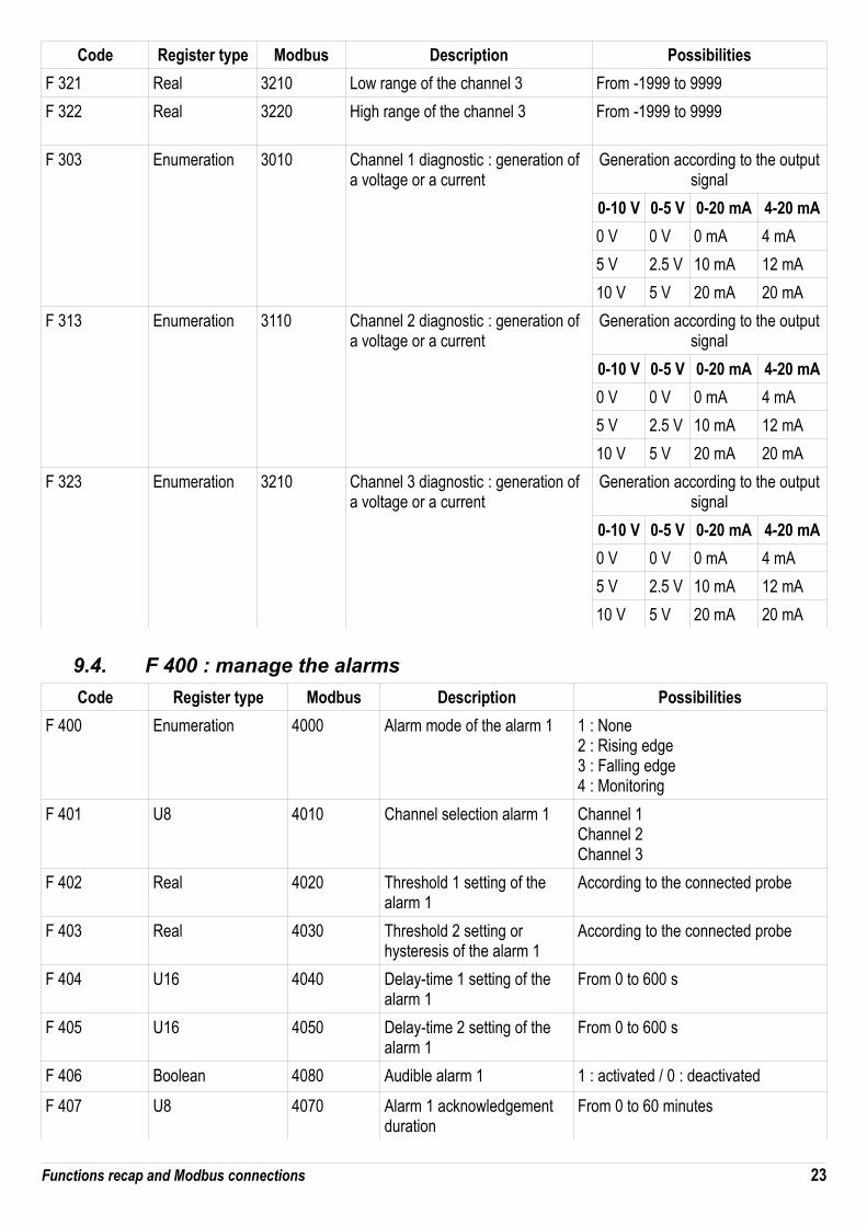
F 321 Real 3210 Low range of the channel 3 From -1999 to 9999
F 322 Real 3220 High range of the channel 3 From -1999 to 9999
F 303 Enumeration 3010 Channel 1 diagnostic : generation of a voltage or a current
Generation according to the outputsignal
0-10 V 0-5 V 0-20 mA 4-20 mA
0 V 0 V 0 mA 4 mA
5 V 2.5 V 10 mA 12 mA
10 V 5 V 20 mA 20 mA
F 313 Enumeration 3110 Channel 2 diagnostic : generation of a voltage or a current
Generation according to the outputsignal
0-10 V 0-5 V 0-20 mA 4-20 mA
0 V 0 V 0 mA 4 mA
5 V 2.5 V 10 mA 12 mA
10 V 5 V 20 mA 20 mA
F 323 Enumeration 3210 Channel 3 diagnostic : generation of a voltage or a current
Generation according to the outputsignal
0-10 V 0-5 V 0-20 mA 4-20 mA
0 V 0 V 0 mA 4 mA
5 V 2.5 V 10 mA 12 mA
10 V 5 V 20 mA 20 mA
9.4. F 400 : manage the alarms
Code Register type Modbus Description Possibilities
F 400 Enumeration 4000 Alarm mode of the alarm 1 1 : None2 : Rising edge3 : Falling edge4 : Monitoring
F 401 U8 4010 Channel selection alarm 1 Channel 1Channel 2Channel 3
F 402 Real 4020 Threshold 1 setting of the alarm 1
According to the connected probe
F 403 Real 4030 Threshold 2 setting or hysteresis of the alarm 1
According to the connected probe
F 404 U16 4040 Delay-time 1 setting of the alarm 1
From 0 to 600 s
F 405 U16 4050 Delay-time 2 setting of the alarm 1
From 0 to 600 s
F 406 Boolean 4080 Audible alarm 1 1 : activated / 0 : deactivated
F 407 U8 4070 Alarm 1 acknowledgement duration
From 0 to 60 minutes
Functions recap and Modbus connections 23

F 410 Enumeration 4100 Alarm mode of the alarm 2 1 : None2 : Rising edge3 : Falling edge4 : Monitoring
F 411 U8 4110 Channel selection alarm 2 Channel 1Channel 2Channel 3
F 412 Real 4120 Threshold 1 setting of the alarm 2
According to the connected probe
F 413 Real 4130 Threshold 2 setting or hysteresis of the alarm 2
According to the connected probe
F 414 U16 4140 Delay-time 1 setting of the alarm 2
From 0 to 600 s
F 415 U16 4150 Delay-time 2 setting of the alarm 2
From 0 to 600 s
F 416 Boolean 4180 Audible alarm 2 1 : activated / 0 : deactivated
F 417 U8 4070 Alarm 2 acknowledgement duration
From 0 to 60 minutes
F 420 Enumeration 4200 Alarm mode of the alarm 3 1 : None2 : Rising edge3 : Falling edge4 : Monitoring
F 421 U8 4210 Channel selection alarm 3 Channel 1Channel 2Channel 3
F 422 Real 4220 Threshold 1 setting of the alarm 3
According to the connected probe
F 423 Real 4230 Threshold 2 setting or hysteresis of the alarm 3
According to the connected probe
F 424 U16 4240 Delay-time 1 setting of the alarm 3
From 0 to 600 s
F 425 U16 4250 Delay-time 2 setting of the alarm 3
From 0 to 600 s
F 426 Boolean 4280 Audible Alarm 3 1 : activated / 0 : deactivated
F 427 U8 4070 Alarm 3 acknowledgement duration
From 0 to 60 minutes
9.5. F 500 : set the measurement
Code Registertype
Modbus Description Possibilities
F 500 U8 5000 Integration of the measurement in pressure (board) From 0 to 9
F 501 U8 5010 Integration of the measurement in air velocity (probe) From 0 to 9
F 502 U8 5020 Integration of the measurement in pressure (probe) From 0 to 9
F 510 U8 5100 Delay-time between 2 autozeros From 0 to 60 min
24 Functions recap and Modbus connections

F 511 Boolean 5110 Instantaneous autozero
F 520 Real 5200 Channel 1 coefficient From 0.01 to 5
F 530 Real 5300 Channel 2 coefficient From 0.01 to 5
F 540 Real 5400 Channel 3 coefficient From 0.01 to 5
F 521 Real 5210 Channel 1 offset According to probe
F 531 Real 5310 Channel 2 offset According to probe
F 541 Real 5410 Channel 3 offset According to probe
Functions recap and Modbus connections 25


NTa
ng –
tran
smitt
er_C
PE31
0-S-
CPE
311-
S –
16/1
2/14
- R
CS
(24)
Pér
igue
ux 3
49 2
82 0
95 N
on-c
ontra
ctua
l doc
umen
t – W
e re
serv
e th
e rig
ht to
mod
ify th
e ch
arac
teris
tics
of o
ur p
rodu
cts.