configuring ospfv2 - cisco.com · the hello packet contains information about the or iginating...
TRANSCRIPT

C H A P T E R
S e n d d o c u m e n t c o m m e n t s t o n e x u s 7 k - d o c f e e d b a c k @ c i s c o . c o m .
6-1Cisco Nexus 7000 Series NX-OS Unicast Routing Configuration Guide, Release 5.x
OL-21548-01
6Configuring OSPFv2
This chapter describes how to configure Open Shortest Path First version 2 (OSPFv2) for IPv4 networks on the Cisco NX-OS device.
This chapter includes the following sections:
• Information About OSPFv2, page 6-1
• Licensing Requirements for OSPFv2, page 6-13
• Prerequisites for OSPFv2, page 6-13
• Guidelines and Limitations for OSPFv2, page 6-13
• Default Settings, page 6-14
• Configuring Basic OSPFv2, page 6-14
• Configuring Advanced OSPFv2, page 6-23
• Verifying the OSPFv2 Configuration, page 6-44
• Monitoring OSPFv2, page 6-45
• Configuration Examples for OSPFv2, page 6-45
• Additional References, page 6-46
• Feature History for OSPFv2, page 6-46
Information About OSPFv2OSPFv2 is an IETF link-state protocol (see the “Link-State Protocols” section on page 1-9) for IPv4 networks. An OSPFv2 router sends a special message, called a hello packet, out each OSPF-enabled interface to discover other OSPFv2 neighbor routers. Once a neighbor is discovered, the two routers compare information in the Hello packet to determine if the routers have compatible configurations. The neighbor routers try to establish adjacency, which means that the routers synchronize their link-state databases to ensure that they have identical OSPFv2 routing information. Adjacent routers share link-state advertisements (LSAs) that include information about the operational state of each link, the cost of the link, and any other neighbor information. The routers then flood these received LSAs out every OSPF-enabled interface so that all OSPFv2 routers eventually have identical link-state databases. When all OSPFv2 routers have identical link-state databases, the network is converged (see the “Convergence” section on page 1-6). Each router then uses Dijkstra’s Shortest Path First (SPF) algorithm to build its route table.
You can divide OSPFv2 networks into areas. Routers send most LSAs only within one area, which reduces the CPU and memory requirements for an OSPF-enabled router.

S e n d d o c u m e n t c o m m e n t s t o n e x u s 7 k - d o c f e e d b a c k @ c i s c o . c o m .
6-2Cisco Nexus 7000 Series NX-OS Unicast Routing Configuration Guide, Release 5.x
OL-21548-01
Chapter 6 Configuring OSPFv2Information About OSPFv2
OSPFv2 supports IPv4, while OSPFv3 supports IPv6. For more information, see Chapter 7, “Configuring OSPFv3.”
Note OSPFv2 on Cisco NX-OS supports RFC 2328. This RFC introduced a different method to calculate route summary costs which is not compatible with the calculation used by RFC1583. RFC 2328 also introduced different selection criteria for AS-external paths. It is important_ to ensure that all routers support the same RFC. RFC. Use the rfc1583compatibility command if your network includes routers that are only compliant with RFC1583. The default supported RFC standard for OSPFv2 may be different for Cisco NX-OS and Cisco IOS. You must make adjustments to set the values identically. See the “OSPF RFC Compatibility Mode Example” section on page 6-45 for more information.
This section includes the following topics:
• Hello Packet, page 6-2
• Neighbors, page 6-3
• Adjacency, page 6-3
• Designated Routers, page 6-3
• Areas, page 6-4
• Link-State Advertisements, page 6-5
• OSPFv2 and the Unicast RIB, page 6-7
• Authentication, page 6-7
• Advanced Features, page 6-8
Hello Packet
OSPFv2 routers periodically send Hello packets on every OSPF-enabled interface. The hello interval determines how frequently the router sends these Hello packets and is configured per interface. OSPFv2 uses Hello packets for the following tasks:
• Neighbor discovery
• Keepalives
• Bidirectional communications
• Designated router election (see the “Designated Routers” section on page 6-3)
The Hello packet contains information about the originating OSPFv2 interface and router, including the assigned OSPFv2 cost of the link, the hello interval, and optional capabilities of the originating router. An OSPFv2 interface that receives these Hello packets determines if the settings are compatible with the receiving interface settings. Compatible interfaces are considered neighbors and are added to the neighbor table (see the “Neighbors” section on page 6-3).
Hello packets also include a list of router IDs for the routers that the originating interface has communicated with. If the receiving interface sees its own router ID in this list, then bidirectional communication has been established between the two interfaces.
OSPFv2 uses Hello packets as a keepalive message to determine if a neighbor is still communicating. If a router does not receive a Hello packet by the configured dead interval (usually a multiple of the hello interval), then the neighbor is removed from the local neighbor table.
S e n d d o c u m e n t c o m m e n t s t o n e x u s 7 k - d o c f e e d b a c k @ c i s c o . c o m .
6-3Cisco Nexus 7000 Series NX-OS Unicast Routing Configuration Guide, Release 5.x
OL-21548-01
Chapter 6 Configuring OSPFv2Information About OSPFv2
Neighbors
An OSPFv2 interface must have a compatible configuration with a remote interface before the two can be considered neighbors. The two OSPFv2 interfaces must match the following criteria:
• Hello interval
• Dead interval
• Area ID (see the “Areas” section on page 6-4)
• Authentication
• Optional capabilities
If there is a match, the following information is entered into the neighbor table:
• Neighbor ID—The router ID of the neighbor.
• Priority—Priority of the neighbor. The priority is used for designated router election (see the “Designated Routers” section on page 6-3).
• State—Indication of whether the neighbor has just been heard from, is in the process of setting up bidirectional communications, is sharing the link-state information, or has achieved full adjacency.
• Dead time—Indication of the time since the last Hello packet was received from this neighbor.
• IP Address—The IP address of the neighbor.
• Designated Router—Indication of whether the neighbor has been declared as the designated router or as the backup designated router (see the “Designated Routers” section on page 6-3).
• Local interface—The local interface that received the Hello packet for this neighbor.
Adjacency
Not all neighbors establish adjacency. Depending on the network type and designated router establishment, some neighbors become fully adjacent and share LSAs with all their neighbors, while other neighbors do not. For more information, see the “Designated Routers” section on page 6-3.
Adjacency is established using Database Description packets, Link State Request packets, and Link State Update packets in OSPF. The Database Description packet includes just the LSA headers from the link-state database of the neighbor (see the “Link-State Database” section on page 6-7). The local router compares these headers with its own link-state database and determines which LSAs are new or updated. The local router sends a Link State Request packet for each LSA that it needs new or updated information on. The neighbor responds with a Link State Update packet. This exchange continues until both routers have the same link-state information.
Designated Routers
Networks with multiple routers present a unique situation for OSPF. If every router floods the network with LSAs, the same link-state information is sent from multiple sources. Depending on the type of network, OSPFv2 might use a single router, the designated router (DR), to control the LSA floods and represent the network to the rest of the OSPFv2 area (see the “Areas” section on page 6-4). If the DR fails, OSPFv2 selects a backup designated router (BDR). If the DR fails, OSPFv2 uses the BDR.
Network types are as follows:

S e n d d o c u m e n t c o m m e n t s t o n e x u s 7 k - d o c f e e d b a c k @ c i s c o . c o m .
6-4Cisco Nexus 7000 Series NX-OS Unicast Routing Configuration Guide, Release 5.x
OL-21548-01
Chapter 6 Configuring OSPFv2Information About OSPFv2
• Point-to-point—A network that exists only between two routers. All neighbors on a point-to-point network establish adjacency and there is no DR.
• Broadcast—A network with multiple routers that can communicate over a shared medium that allows broadcast traffic, such as Ethernet. OSPFv2 routers establish a DR and BDR that controls LSA flooding on the network. OSPFv2 uses the well-known IPv4 multicast addresses 224.0.0.5 and a MAC address of 0100.5300.0005 to communicate with neighbors.
The DR and BDR are selected based on the information in the Hello packet. When an interface sends a Hello packet, it sets the priority field and the DR and BDR field if it knows who the DR and BDR are. The routers follow an election procedure based on which routers declare themselves in the DR and BDR fields and the priority field in the Hello packet. As a final tie breaker, OSPFv2 chooses the highest router IDs as the DR and BDR.
All other routers establish adjacency with the DR and the BDR and use the IPv4 multicast address 224.0.0.6 to send LSA updates to the DR and BDR. Figure 6-1 shows this adjacency relationship between all routers and the DR.
DRs are based on a router interface. A router might be the DR for one network and not for another network on a different interface.
Figure 6-1 DR in Multi-Access Network
Areas
You can limit the CPU and memory requirements that OSPFv2 puts on the routers by dividing an OSPFv2 network into areas. An area is a logical division of routers and links within an OSPFv2 domain that creates separate subdomains. LSA flooding is contained within an area, and the link-state database is limited to links within the area. You can assign an area ID to the interfaces within the defined area. The Area ID is a 32-bit value that you can enter as a number or in dotted decimal notation, such as 10.2.3.1.
Cisco NX-OS always displays the area in dotted decimal notation.
Router A Router B Router C
Router ERouter Dor DR
= Multi-access network= Logical connectivity to Designated Router for OSPF 18
2982

S e n d d o c u m e n t c o m m e n t s t o n e x u s 7 k - d o c f e e d b a c k @ c i s c o . c o m .
6-5Cisco Nexus 7000 Series NX-OS Unicast Routing Configuration Guide, Release 5.x
OL-21548-01
Chapter 6 Configuring OSPFv2Information About OSPFv2
If you define more than one area in an OSPFv2 network, you must also define the backbone area, which has the reserved area ID of 0. If you have more than one area, then one or more routers become area border routers (ABRs). An ABR connects to both the backbone area and at least one other defined area (see Figure 6-2).
Figure 6-2 OSPFv2 Areas
The ABR has a separate link-state database for each area to which it connects. The ABR sends Network Summary (type 3) LSAs (see the “Route Summarization” section on page 6-10) from one connected area to the backbone area. The backbone area sends summarized information about one area to another area. In Figure 6-2, Area 0 sends summarized information about Area 5 to Area 3.
OSPFv2 defines one other router type: the autonomous system boundary router (ASBR). This router connects an OSPFv2 area to another autonomous system. An autonomous system is a network controlled by a single technical administration entity. OSPFv2 can redistribute its routing information into another autonomous system or receive redistributed routes from another autonomous system. For more information, see the “Advanced Features” section on page 6-8.)
Link-State Advertisements
OSPFv2 uses link-state advertisements (LSAs) to build its routing table.
This section includes the following topics:
• LSA Types, page 6-5
• Link Cost, page 6-6
• Flooding and LSA Group Pacing, page 6-6
• Link-State Database, page 6-7
• Opaque LSAs, page 6-7
LSA Types
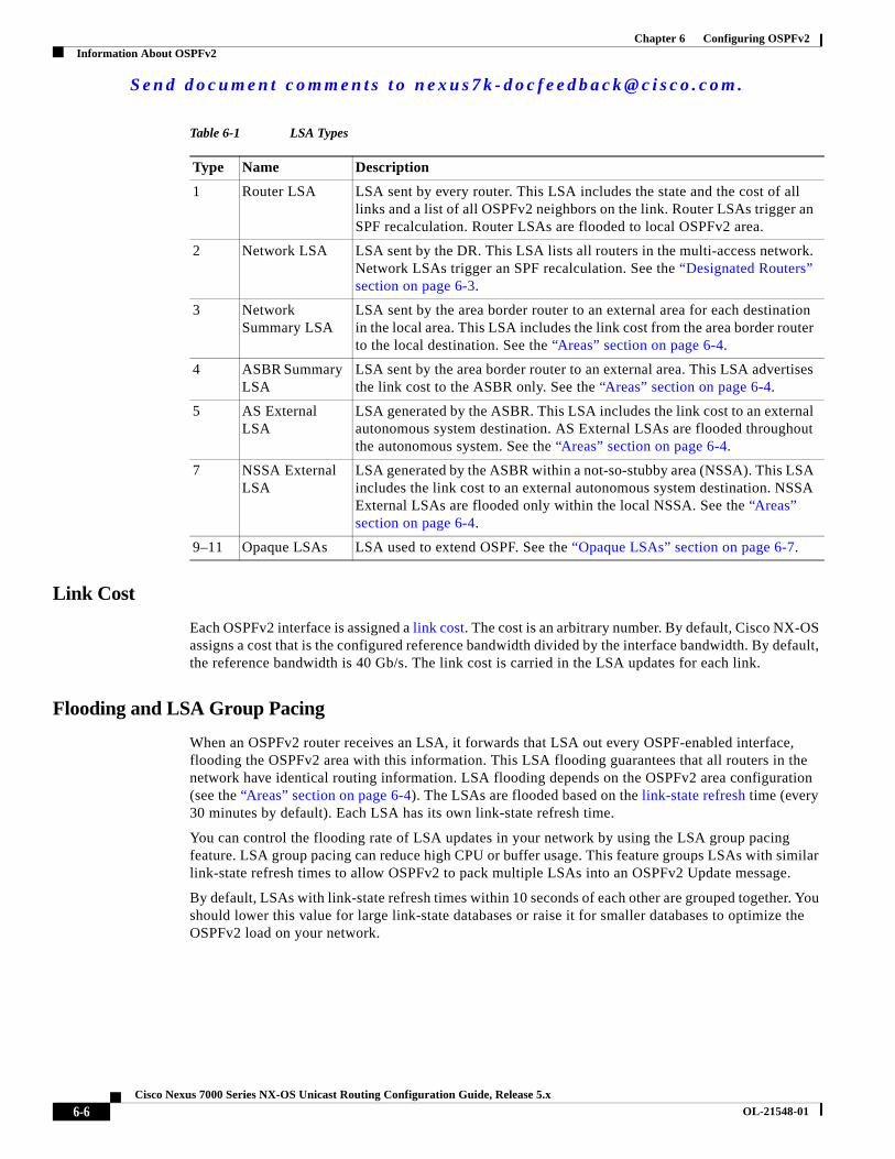
Table 6-1 shows the LSA types supported by Cisco NX-OS.
ABR1
ABR2
Area 0 Area 3
Area 5
1829
83
S e n d d o c u m e n t c o m m e n t s t o n e x u s 7 k - d o c f e e d b a c k @ c i s c o . c o m .
6-6Cisco Nexus 7000 Series NX-OS Unicast Routing Configuration Guide, Release 5.x
OL-21548-01
Chapter 6 Configuring OSPFv2Information About OSPFv2
Link Cost
Each OSPFv2 interface is assigned a link cost. The cost is an arbitrary number. By default, Cisco NX-OS assigns a cost that is the configured reference bandwidth divided by the interface bandwidth. By default, the reference bandwidth is 40 Gb/s. The link cost is carried in the LSA updates for each link.
Flooding and LSA Group Pacing
When an OSPFv2 router receives an LSA, it forwards that LSA out every OSPF-enabled interface, flooding the OSPFv2 area with this information. This LSA flooding guarantees that all routers in the network have identical routing information. LSA flooding depends on the OSPFv2 area configuration (see the “Areas” section on page 6-4). The LSAs are flooded based on the link-state refresh time (every 30 minutes by default). Each LSA has its own link-state refresh time.
You can control the flooding rate of LSA updates in your network by using the LSA group pacing feature. LSA group pacing can reduce high CPU or buffer usage. This feature groups LSAs with similar link-state refresh times to allow OSPFv2 to pack multiple LSAs into an OSPFv2 Update message.
By default, LSAs with link-state refresh times within 10 seconds of each other are grouped together. You should lower this value for large link-state databases or raise it for smaller databases to optimize the OSPFv2 load on your network.
Table 6-1 LSA Types
Type Name Description
1 Router LSA LSA sent by every router. This LSA includes the state and the cost of all links and a list of all OSPFv2 neighbors on the link. Router LSAs trigger an SPF recalculation. Router LSAs are flooded to local OSPFv2 area.
2 Network LSA LSA sent by the DR. This LSA lists all routers in the multi-access network. Network LSAs trigger an SPF recalculation. See the “Designated Routers” section on page 6-3.
3 Network Summary LSA
LSA sent by the area border router to an external area for each destination in the local area. This LSA includes the link cost from the area border router to the local destination. See the “Areas” section on page 6-4.
4 ASBR Summary LSA
LSA sent by the area border router to an external area. This LSA advertises the link cost to the ASBR only. See the “Areas” section on page 6-4.
5 AS External LSA
LSA generated by the ASBR. This LSA includes the link cost to an external autonomous system destination. AS External LSAs are flooded throughout the autonomous system. See the “Areas” section on page 6-4.
7 NSSA External LSA
LSA generated by the ASBR within a not-so-stubby area (NSSA). This LSA includes the link cost to an external autonomous system destination. NSSA External LSAs are flooded only within the local NSSA. See the “Areas” section on page 6-4.
9–11 Opaque LSAs LSA used to extend OSPF. See the “Opaque LSAs” section on page 6-7.

S e n d d o c u m e n t c o m m e n t s t o n e x u s 7 k - d o c f e e d b a c k @ c i s c o . c o m .
6-7Cisco Nexus 7000 Series NX-OS Unicast Routing Configuration Guide, Release 5.x
OL-21548-01
Chapter 6 Configuring OSPFv2Information About OSPFv2
Link-State Database
Each router maintains a link-state database for the OSPFv2 network. This database contains all the collected LSAs, and includes information on all the routes through the network. OSPFv2 uses this information to calculate the bast path to each destination and populates the routing table with these best paths.
LSAs are removed from the link-state database if no LSA update has been received within a set interval, called the MaxAge. Routers flood a repeat of the LSA every 30 minutes to prevent accurate link-state information from being aged out. Cisco NX-OS supports the LSA grouping feature to prevent all LSAs from refreshing at the same time. For more information, see the “Flooding and LSA Group Pacing” section on page 6-6.
Opaque LSAs
Opaque LSAs allow you to extend OSPF functionality. Opaque LSAs consist of a standard LSA header followed by application-specific information. This information might be used by OSPFv2 or by other applications. OSPFv2 uses Opaque LSAs to support OSPFv2 Graceful Restart capability (see the “High Availability and Graceful Restart” section on page 6-11). Three Opaque LSA types are defined as follows:
• LSA type 9—Flooded to the local network.
• LSA type 10—Flooded to the local area.
• LSA type 11—Flooded to the local autonomous system.
OSPFv2 and the Unicast RIB
OSPFv2 runs the Dijkstra shortest path first algorithm on the link-state database. This algorithm selects the best path to each destination based on the sum of all the link costs for each link in the path. The resultant shortest path for each destination is then put in the OSPFv2 route table. When the OSPFv2 network is converged, this route table feeds into the unicast RIB. OSPFv2 communicates with the unicast RIB to do the following:
• Add or remove routes
• Handle route redistribution from other protocols
• Provide convergence updates to remove stale OSPFv2 routes and for stub router advertisements (see the “OSPFv2 Stub Router Advertisements” section on page 6-12)
OSPFv2 also runs a modified Dijkstra algorithm for fast recalculation for summary and external (type 3, 4, 5, and 7) LSA changes.
Authentication
You can configure authentication on OSPFv2 messages to prevent unauthorized or invalid routing updates in your network. Cisco NX-OS supports two authentication methods:
• Simple password authentication
• MD5 authentication digest
You can configure the OSPFv2 authentication for an OSPFv2 area or per interface.
S e n d d o c u m e n t c o m m e n t s t o n e x u s 7 k - d o c f e e d b a c k @ c i s c o . c o m .
6-8Cisco Nexus 7000 Series NX-OS Unicast Routing Configuration Guide, Release 5.x
OL-21548-01
Chapter 6 Configuring OSPFv2Information About OSPFv2
Simple Password Authentication
Simple password authentication uses a simple clear-text password that is sent as part of the OSPFv2 message. The receiving OSPFv2 router must be configured with the same clear-text password to accept the OSPFv2 message as a valid route update. Because the password is in clear text, anyone who can watch traffic on the network can learn the password.
MD5 Authentication
You should use MD5 authentication to authenticate OSPFv2 messages. You configure a password that is shared at the local router and all remote OSPFv2 neighbors. For each OSPFv2 message, Cisco NX-OS creates an MD5 one-way message digest based on the message itself and the encrypted password. The interface sends this digest with the OSPFv2 message. The receiving OSPFv2 neighbor validates the digest using the same encrypted password. If the message has not changed, the digest calculation is identical and the OSPFv2 message is considered valid.
MD5 authentication includes a sequence number with each OSPFv2 message to ensure that no message is replayed in the network.
Advanced Features
Cisco NX-OS supports advanced OSPFv2 features that enhance the usability and scalability of OSPFv2 in the network. This section includes the following topics:
• Stub Area, page 6-8
• Not-So-Stubby Area, page 6-9
• Virtual Links, page 6-9
• Route Redistribution, page 6-10
• Route Summarization, page 6-10
• High Availability and Graceful Restart, page 6-11
• OSPFv2 Stub Router Advertisements, page 6-12
• Multiple OSPFv2 Instances, page 6-12
• SPF Optimization, page 6-12
• BFD, page 6-12
• Virtualization Support, page 6-12
Stub Area
You can limit the amount of external routing information that floods an area by making it a stub area. A stub area is an area that does not allow AS External (type 5) LSAs (see the “Link-State Advertisements” section on page 6-5). These LSAs are usually flooded throughout the local autonomous system to propagate external route information. Stub areas have the following requirements:
• All routers in the stub area are stub routers. See the “Stub Routing” section on page 1-7.
• No ASBR routers exist in the stub area.
• You cannot configure virtual links in the stub area.

S e n d d o c u m e n t c o m m e n t s t o n e x u s 7 k - d o c f e e d b a c k @ c i s c o . c o m .
6-9Cisco Nexus 7000 Series NX-OS Unicast Routing Configuration Guide, Release 5.x
OL-21548-01
Chapter 6 Configuring OSPFv2Information About OSPFv2
Figure 6-3 shows an example of an OSPFv2 autonomous system where all routers in area 0.0.0.10 have to go through the ABR to reach external autonomous systems. Area 0.0.0.10 can be configured as a stub area.
Figure 6-3 Stub Area
Stub areas use a default route for all traffic that must go through the backbone area to the external autonomous system. The default route is 0.0.0.0 for IPv4.
Not-So-Stubby Area
A Not-so-Stubby Area (NSSA) is similar to a stub area, except that an NSSA allows you to import autonomous system external routes within an NSSA using redistribution. The NSSA ASBR redistributes these routes and generates NSSA External (type 7) LSAs that it floods throughout the NSSA. You can optionally configure the ABR that connects the NSSA to other areas to translate this NSSA External LSA to AS External (type 5) LSAs. The ABR then floods these AS External LSAs throughout the OSPFv2 autonomous system. Summarization and filtering are supported during the translation. See the “Link-State Advertisements” section on page 6-5 for information about NSSA External LSAs.
You can, for example, use NSSA to simplify administration if you are connecting a central site using OSPFv2 to a remote site that is using a different routing protocol. Before NSSA, the connection between the corporate site border router and a remote router could not be run as an OSPFv2 stub area because routes for the remote site could not be redistributed into a stub area. With NSSA, you can extend OSPFv2 to cover the remote connection by defining the area between the corporate router and remote router as an NSSA (see the “Configuring NSSA” section on page 6-27).
The backbone Area 0 cannot be an NSSA.
Virtual Links
Virtual links allow you to connect an OSPFv2 area ABR to a backbone area ABR when a direct physical connection is not available. Figure 6-4 shows a virtual link that connects Area 3 to the backbone area through Area 5.
ABR
ASBR
Backbone Area 10
1829
84
Stub area

S e n d d o c u m e n t c o m m e n t s t o n e x u s 7 k - d o c f e e d b a c k @ c i s c o . c o m .
6-10Cisco Nexus 7000 Series NX-OS Unicast Routing Configuration Guide, Release 5.x
OL-21548-01
Chapter 6 Configuring OSPFv2Information About OSPFv2
Figure 6-4 Virtual Links
You can also use virtual links to temporarily recover from a partitioned area, which occurs when a link within the area fails, isolating part of the area from reaching the designated ABR to the backbone area.
Route Redistribution
OSPFv2 can learn routes from other routing protocols by using route redistribution. See the “Route Redistribution” section on page 1-6. You configure OSPFv2 to assign a link cost for these redistributed routes or a default link cost for all redistributed routes.
Route redistribution uses route maps to control which external routes are redistributed. You must configure a route map with the redistribution to control which routes are passed into OSPFv2. A route map allows you to filter routes based on attributes such as the destination, origination protocol, route type, route tag, and so on. You can use route maps to modify parameters in the AS External (type 5) and NSSA External (type 7) LSAs before these external routes are advertised in the local OSPFv2 autonomous system. See Chapter 16, “Configuring Route Policy Manager,” for information about configuring route maps.
Route Summarization
Because OSPFv2 shares all learned routes with every OSPF-enabled router, you might want to use route summarization to reduce the number of unique routes that are flooded to every OSPF-enabled router. Route summarization simplifies route tables by replacing more-specific addresses with an address that represents all the specific addresses. For example, you can replace 10.1.1.0/24, 10.1.2.0/24, and 10.1.3.0/24 with one summary address, 10.1.0.0/16.
Typically, you would summarize at the boundaries of area border routers (ABRs). Although you could configure summarization between any two areas, it is better to summarize in the direction of the backbone so that the backbone receives all the aggregate addresses and injects them, already summarized, into other areas. The two types of summarization are as follows:
• Inter-area route summarization
• External route summarization
ABR1ABR2
Area 0
Area 3Area 5
1829
85
S e n d d o c u m e n t c o m m e n t s t o n e x u s 7 k - d o c f e e d b a c k @ c i s c o . c o m .
6-11Cisco Nexus 7000 Series NX-OS Unicast Routing Configuration Guide, Release 5.x
OL-21548-01
Chapter 6 Configuring OSPFv2Information About OSPFv2
You configure inter-area route summarization on ABRs, summarizing routes between areas in the autonomous system. To take advantage of summarization, you should assign network numbers in areas in a contiguous way to be able to lump these addresses into one range.
External route summarization is specific to external routes that are injected into OSPFv2 using route redistribution. You should make sure that external ranges that are being summarized are contiguous. Summarizing overlapping ranges from two different routers could cause packets to be sent to the wrong destination. Configure external route summarization on ASBRs that are redistributing routes into OSPF.
When you configure a summary address, Cisco NX-OS automatically configures a discard route for the summary address to prevent routing black holes and route loops.
High Availability and Graceful Restart
Cisco NX-OS provides a multilevel high-availability architecture. OSPFv2 supports stateful restart, which is also referred to as non-stop routing (NSR). If OSPFv2 experiences problems, it attempts to restart from its previous run-time state. The neighbors do not register any neighbor event in this case. If the first restart is not successful and another problem occurs, OSPFv2 attempts a graceful restart.
A graceful restart, or nonstop forwarding (NSF), allows OSPFv2 to remain in the data forwarding path through a process restart. When OSPFv2 needs to perform a graceful restart, it sends a link-local opaque (type 9) LSA, called a grace LSA (see the “Opaque LSAs” section on page 6-7). This restarting OSPFv2 platform is called NSF capable.
The grace LSA includes a grace period, which is a specified time that the neighbor OSPFv2 interfaces hold onto the LSAs from the restarting OSPFv2 interface. (Typically, OSPFv2 tears down the adjacency and discards all LSAs from a down or restarting OSPFv2 interface.) The participating neighbors, which are called NSF helpers, keep all LSAs that originate from the restarting OSPFv2 interface as if the interface was still adjacent.
When the restarting OSPFv2 interface is operational again, it rediscovers its neighbors, establishes adjacency, and starts sending its LSA updates again. At this point, the NSF helpers recognize that the graceful restart has finished.
Stateful restart is used in the following scenarios:
• First recovery attempt after the process experiences problems
• ISSU
• User-initiated switchover using the system switchover command
Graceful restart is used in the following scenarios:
• Second recovery attempt after the process experiences problems within a 4-minute interval
• Manual restart of the process using the restart ospf command
• Active supervisor removal
• Active supervisor reload using the reload module active-sup command
S e n d d o c u m e n t c o m m e n t s t o n e x u s 7 k - d o c f e e d b a c k @ c i s c o . c o m .
6-12Cisco Nexus 7000 Series NX-OS Unicast Routing Configuration Guide, Release 5.x
OL-21548-01
Chapter 6 Configuring OSPFv2Information About OSPFv2
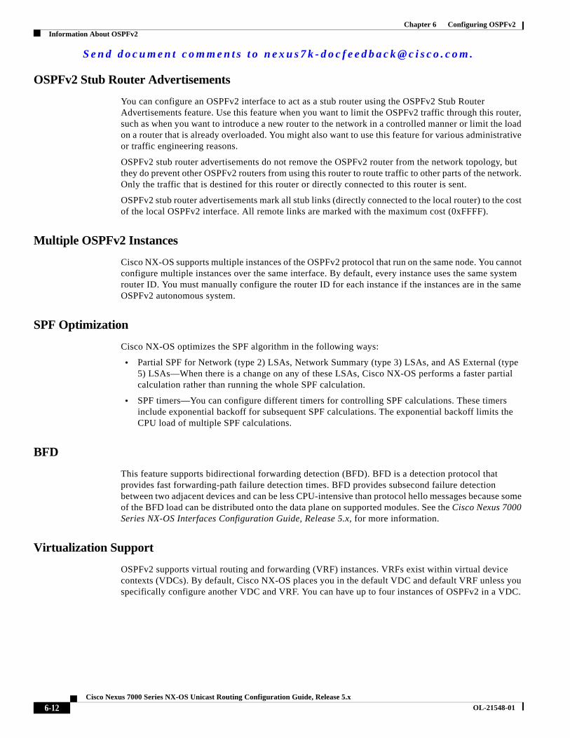
OSPFv2 Stub Router Advertisements
You can configure an OSPFv2 interface to act as a stub router using the OSPFv2 Stub Router Advertisements feature. Use this feature when you want to limit the OSPFv2 traffic through this router, such as when you want to introduce a new router to the network in a controlled manner or limit the load on a router that is already overloaded. You might also want to use this feature for various administrative or traffic engineering reasons.
OSPFv2 stub router advertisements do not remove the OSPFv2 router from the network topology, but they do prevent other OSPFv2 routers from using this router to route traffic to other parts of the network. Only the traffic that is destined for this router or directly connected to this router is sent.
OSPFv2 stub router advertisements mark all stub links (directly connected to the local router) to the cost of the local OSPFv2 interface. All remote links are marked with the maximum cost (0xFFFF).
Multiple OSPFv2 Instances
Cisco NX-OS supports multiple instances of the OSPFv2 protocol that run on the same node. You cannot configure multiple instances over the same interface. By default, every instance uses the same system router ID. You must manually configure the router ID for each instance if the instances are in the same OSPFv2 autonomous system.
SPF Optimization
Cisco NX-OS optimizes the SPF algorithm in the following ways:
• Partial SPF for Network (type 2) LSAs, Network Summary (type 3) LSAs, and AS External (type 5) LSAs—When there is a change on any of these LSAs, Cisco NX-OS performs a faster partial calculation rather than running the whole SPF calculation.
• SPF timers—You can configure different timers for controlling SPF calculations. These timers include exponential backoff for subsequent SPF calculations. The exponential backoff limits the CPU load of multiple SPF calculations.
BFD
This feature supports bidirectional forwarding detection (BFD). BFD is a detection protocol that provides fast forwarding-path failure detection times. BFD provides subsecond failure detection between two adjacent devices and can be less CPU-intensive than protocol hello messages because some of the BFD load can be distributed onto the data plane on supported modules. See the Cisco Nexus 7000 Series NX-OS Interfaces Configuration Guide, Release 5.x, for more information.
Virtualization Support
OSPFv2 supports virtual routing and forwarding (VRF) instances. VRFs exist within virtual device contexts (VDCs). By default, Cisco NX-OS places you in the default VDC and default VRF unless you specifically configure another VDC and VRF. You can have up to four instances of OSPFv2 in a VDC.

S e n d d o c u m e n t c o m m e n t s t o n e x u s 7 k - d o c f e e d b a c k @ c i s c o . c o m .
6-13Cisco Nexus 7000 Series NX-OS Unicast Routing Configuration Guide, Release 5.x
OL-21548-01
Chapter 6 Configuring OSPFv2Licensing Requirements for OSPFv2
Each OSPFv2 instance can support multiple VRFs, up to the system limit. For more information, see the Cisco Nexus 7000 Series NX-OS Virtual Device Context Configuration Guide, Release 5.x, and see Chapter 14, “Configuring Layer 3 Virtualization.”
Licensing Requirements for OSPFv2The following table shows the licensing requirements for this feature:
Prerequisites for OSPFv2OSPFv2 has the following prerequisites:
• You must be familiar with routing fundamentals to configure OSPF.
• You are logged on to the switch.
• You have configured at least one interface for IPv4 that can communicate with a remote OSPFv2 neighbor.
• You have installed the Enterprise Services license.
• You have completed the OSPFv2 network strategy and planning for your network. For example, you must decide whether multiple areas are required.
• You have enabled the OSPF feature (see the “Enabling OSPFv2” section on page 6-14).
• You have installed the Advanced Services license and entered the desired VDC (see the Cisco Nexus 7000 Series NX-OS Virtual Device Context Configuration Guide, Release 5.x) if you are configuring VDCs.
Guidelines and Limitations for OSPFv2OSPFv2 has the following configuration guidelines and limitations:
• You can have up to four instances of OSPFv2 in a VDC.
• Cisco NX-OS displays areas in dotted decimal notation regardless of whether you enter the area in decimal or dotted decimal notation.
• All OSPFv2 routers must operate in the same RFC compatibility mode. OSPFv2 for Cisco NX-OS complies with RFC 2328. Use the rfc1583compatibility command in router configuration mode if your network includes routers that support only RFC 1583.
Product License Requirement
Cisco NX-OS OSPFv2 requires an Enterprise Services license. For a complete explanation of the Cisco NX-OS licensing scheme and how to obtain and apply licenses, see the Cisco NX-OS Licensing Guide.
S e n d d o c u m e n t c o m m e n t s t o n e x u s 7 k - d o c f e e d b a c k @ c i s c o . c o m .
6-14Cisco Nexus 7000 Series NX-OS Unicast Routing Configuration Guide, Release 5.x
OL-21548-01
Chapter 6 Configuring OSPFv2Default Settings
Note If you are familiar with the Cisco IOS CLI, be aware that the Cisco NX-OS commands for this feature might differ from the Cisco IOS commands that you would use.
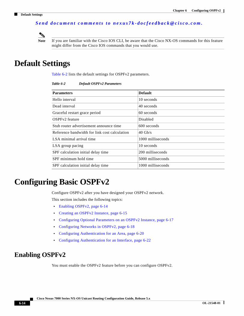
Default SettingsTable 6-2 lists the default settings for OSPFv2 parameters.
Configuring Basic OSPFv2Configure OSPFv2 after you have designed your OSPFv2 network.
This section includes the following topics:
• Enabling OSPFv2, page 6-14
• Creating an OSPFv2 Instance, page 6-15
• Configuring Optional Parameters on an OSPFv2 Instance, page 6-17
• Configuring Networks in OSPFv2, page 6-18
• Configuring Authentication for an Area, page 6-20
• Configuring Authentication for an Interface, page 6-22
Enabling OSPFv2
You must enable the OSPFv2 feature before you can configure OSPFv2.
Table 6-2 Default OSPFv2 Parameters
Parameters Default
Hello interval 10 seconds
Dead interval 40 seconds
Graceful restart grace period 60 seconds
OSPFv2 feature Disabled
Stub router advertisement announce time 600 seconds
Reference bandwidth for link cost calculation 40 Gb/s
LSA minimal arrival time 1000 milliseconds
LSA group pacing 10 seconds
SPF calculation initial delay time 200 milliseconds
SPF minimum hold time 5000 milliseconds
SPF calculation initial delay time 1000 milliseconds

S e n d d o c u m e n t c o m m e n t s t o n e x u s 7 k - d o c f e e d b a c k @ c i s c o . c o m .
6-15Cisco Nexus 7000 Series NX-OS Unicast Routing Configuration Guide, Release 5.x
OL-21548-01
Chapter 6 Configuring OSPFv2Configuring Basic OSPFv2
BEFORE YOU BEGIN
Ensure that you are in the correct VDC (or use the switchto vdc command).
SUMMARY STEPS
1. configure terminal
2. feature ospf
3. (Optional) show feature
4. (Optional) copy running-config startup-config
DETAILED STEPS
To disable the OSPFv2 feature and remove all associated configuration, use the no feature ospf command in configuration mode:
Creating an OSPFv2 Instance
The first step in configuring OSPFv2 is to create an OSPFv2 instance. You assign a unique instance tag for this OSPFv2 instance. The instance tag can be any string.
For more information about OSPFv2 instance parameters, see the “Configuring Advanced OSPFv2” section on page 6-23.
Command Purpose
Step 1 configure terminal
Example:switch# configure terminalswitch(config)#
Enters configuration mode.
Step 2 feature ospf
Example:switch(config)# feature ospf
Enables the OSPFv2 feature.
Step 3 show feature
Example:switch(config)# show feature
(Optional) Displays enabled and disabled features.
Step 4 copy running-config startup-config
Example:switch(config)# copy running-config startup-config
(Optional) Saves this configuration change.
Command Purpose
no feature ospf
Example:switch(config)# no feature ospf
Disables the OSPFv2 feature and removes all associated configuration.
S e n d d o c u m e n t c o m m e n t s t o n e x u s 7 k - d o c f e e d b a c k @ c i s c o . c o m .
6-16Cisco Nexus 7000 Series NX-OS Unicast Routing Configuration Guide, Release 5.x
OL-21548-01
Chapter 6 Configuring OSPFv2Configuring Basic OSPFv2
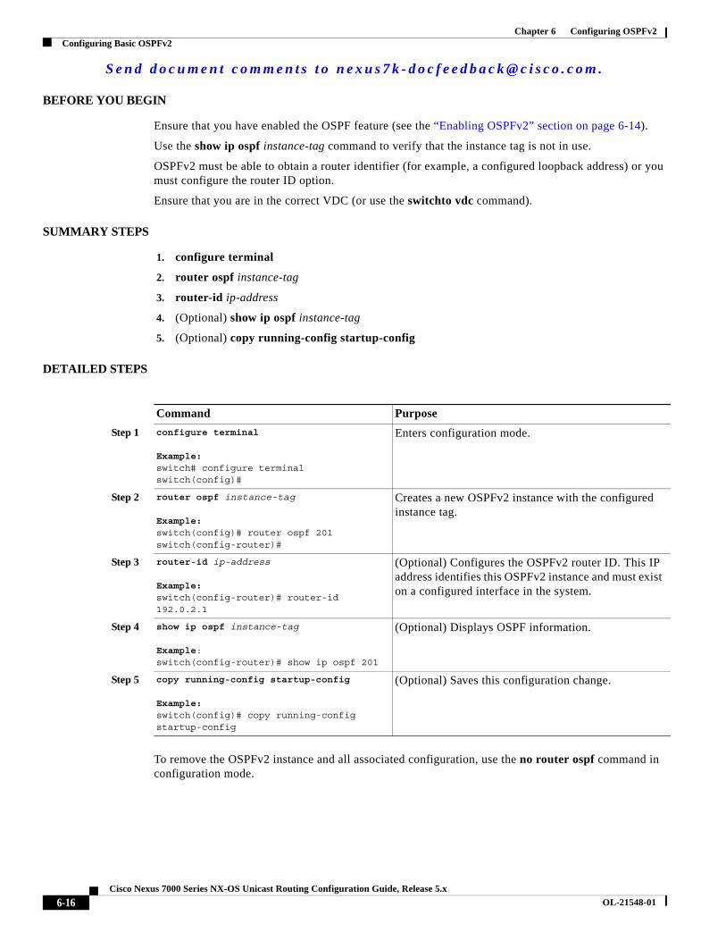
BEFORE YOU BEGIN
Ensure that you have enabled the OSPF feature (see the “Enabling OSPFv2” section on page 6-14).
Use the show ip ospf instance-tag command to verify that the instance tag is not in use.
OSPFv2 must be able to obtain a router identifier (for example, a configured loopback address) or you must configure the router ID option.
Ensure that you are in the correct VDC (or use the switchto vdc command).
SUMMARY STEPS
1. configure terminal
2. router ospf instance-tag
3. router-id ip-address
4. (Optional) show ip ospf instance-tag
5. (Optional) copy running-config startup-config
DETAILED STEPS
To remove the OSPFv2 instance and all associated configuration, use the no router ospf command in configuration mode.
Command Purpose
Step 1 configure terminal
Example:switch# configure terminalswitch(config)#
Enters configuration mode.
Step 2 router ospf instance-tag
Example:switch(config)# router ospf 201switch(config-router)#
Creates a new OSPFv2 instance with the configured instance tag.
Step 3 router-id ip-address
Example:switch(config-router)# router-id 192.0.2.1
(Optional) Configures the OSPFv2 router ID. This IP address identifies this OSPFv2 instance and must exist on a configured interface in the system.
Step 4 show ip ospf instance-tag
Example:switch(config-router)# show ip ospf 201
(Optional) Displays OSPF information.
Step 5 copy running-config startup-config
Example:switch(config)# copy running-config startup-config
(Optional) Saves this configuration change.

S e n d d o c u m e n t c o m m e n t s t o n e x u s 7 k - d o c f e e d b a c k @ c i s c o . c o m .
6-17Cisco Nexus 7000 Series NX-OS Unicast Routing Configuration Guide, Release 5.x
OL-21548-01
Chapter 6 Configuring OSPFv2Configuring Basic OSPFv2
Note This command does not remove the OSPF configuration in interface mode. You must manually remove any OSPFv2 commands configured in interface mode.
Configuring Optional Parameters on an OSPFv2 Instance
You can configure optional parameters for OSPF.
For more information about OSPFv2 instance parameters, see the “Configuring Advanced OSPFv2” section on page 6-23.
BEFORE YOU BEGIN
Ensure that you have enabled the OSPF feature (see the “Enabling OSPFv2” section on page 6-14).
OSPFv2 must be able to obtain a router identifier (for example, a configured loopback address) or you must configure the router ID option.
Ensure that you are in the correct VDC (or use the switchto vdc command).
DETAILED STEPS
You can configure the following optional parameters for OSPFv2 in router configuration mode:
Command Purpose
no router ospf instance-tag
Example:switch(config)# no router ospf 201
Deletes the OSPF instance and the associated configuration.
Command Purpose
distance number
Example:switch(config-router)# distance 25
Configures the administrative distance for this OSPFv2 instance. The range is from 1 to 255. The default is 110.
log-adjacency-changes [detail]
Example:switch(config-router)# log-adjacency-changes
Generates a system message whenever a neighbor changes state.
maximum-paths path-number
Example:switch(config-router)# maximum-paths 4
Configures the maximum number of equal OSPFv2 paths to a destination in the route table. This command is used for load balancing. The range is from 1 to 16. The default is 8.
passive-interface default
Example:switch(config-router)# passive-interface default
Suppresses routing updates on all interfaces. This command is overridden by the VRF or interface command mode configuration.

S e n d d o c u m e n t c o m m e n t s t o n e x u s 7 k - d o c f e e d b a c k @ c i s c o . c o m .
6-18Cisco Nexus 7000 Series NX-OS Unicast Routing Configuration Guide, Release 5.x
OL-21548-01
Chapter 6 Configuring OSPFv2Configuring Basic OSPFv2
This example shows how to create an OSPFv2 instance:
switch# configure terminalswitch(config)# router ospf 201switch(config-router)# copy running-config startup-config
Configuring Networks in OSPFv2
You can configure a network to OSPFv2 by associating it through the interface that the router uses to connect to that network (see the “Neighbors” section on page 6-3). You can add all networks to the default backbone area (Area 0), or you can create new areas using any decimal number or an IP address.
Note All areas must connect to the backbone area either directly or through a virtual link.
Note OSPF is not enabled on an interface until you configure a valid IP address for that interface.
BEFORE YOU BEGIN
Ensure that you have enabled the OSPF feature (see the “Enabling OSPFv2” section on page 6-14).
Ensure that you are in the correct VDC (or use the switchto vdc command).
SUMMARY STEPS
1. configure terminal
2. interface interface-type slot/port
3. ip address ip-prefix/length
4. ip router ospf instance-tag area area-id [secondaries none]
5. (Optional) show ip ospf instance-tag interface interface-type slot/port
6. (Optional) copy running-config startup-config
DETAILED STEPS
Command Purpose
Step 1 configure terminal
Example:switch# configure terminalswitch(config)#
Enters configuration mode.
Step 2 interface interface-type slot/port
Example:switch(config)# interface ethernet 1/2switch(config-if)#
Enters interface configuration mode.

S e n d d o c u m e n t c o m m e n t s t o n e x u s 7 k - d o c f e e d b a c k @ c i s c o . c o m .
6-19Cisco Nexus 7000 Series NX-OS Unicast Routing Configuration Guide, Release 5.x
OL-21548-01
Chapter 6 Configuring OSPFv2Configuring Basic OSPFv2
You can configure the following optional parameters for OSPFv2 in interface configuration mode:
Step 3 ip address ip-prefix/length
Example:switch(config-if)# ip address 192.0.2.1/16
Assigns an IP address and subnet mask to this interface.
Step 4 ip router ospf instance-tag area area-id [secondaries none]
Example:switch(config-if)# ip router ospf 201 area 0.0.0.15
Adds the interface to the OSPFv2 instance and area.
Step 5 show ip ospf instance-tag interface interface-type slot/port
Example:switch(config-if)# show ip ospf 201 interface ethernet 1/2
(Optional) Displays OSPF information.
Step 6 copy running-config startup-config
Example:switch(config)# copy running-config startup-config
(Optional) Saves this configuration change.
Command Purpose
Command Purpose
ip ospf cost number
Example:switch(config-if)# ip ospf cost 25
Configures the OSPFv2 cost metric for this interface. The default is to calculate cost metric, based on the reference bandwidth and interface bandwidth. The range is from 1 to 65535.
ip ospf dead-interval seconds
Example:switch(config-if)# ip ospf dead-interval 50
Configures the OSPFv2 dead interval, in seconds. The range is from 1 to 65535. The default is four times the hello interval, in seconds.
ip ospf hello-interval seconds
Example:switch(config-if)# ip ospf hello-interval 25
Configures the OSPFv2 hello interval, in seconds. The range is from 1 to 65535. The default is 10 seconds.
ip ospf mtu-ignore
Example:switch(config-if)# ip ospf mtu-ignore
Configures OSPFv2 to ignore any IP MTU mismatch with a neighbor. The default is to not establish adjacency if the neighbor MTU does not match the local interface MTU.
[default | no] ip ospf passive-interface
Example:switch(config-if)# ip ospf passive-interface
Suppresses routing updates on the interface. This command overrides the router or VRF command mode configuration. The default option removes this interface mode command and reverts to the router or VRF configuration, if present.

S e n d d o c u m e n t c o m m e n t s t o n e x u s 7 k - d o c f e e d b a c k @ c i s c o . c o m .
6-20Cisco Nexus 7000 Series NX-OS Unicast Routing Configuration Guide, Release 5.x
OL-21548-01
Chapter 6 Configuring OSPFv2Configuring Basic OSPFv2
This example shows how to add a network area 0.0.0.10 in OSPFv2 instance 201:
switch# configure terminalswitch(config)# interface ethernet 1/2switch(config-if)# ip address 192.0.2.1/16switch(config-if)# ip router ospf 201 area 0.0.0.10switch(config-if)# copy running-config startup-config
Use the show ip ospf interface command to verify the interface configuration. Use the show ip ospf neighbor command to see the neighbors for this interface.
Configuring Authentication for an Area
You can configure authentication for all networks in an area or for individual interfaces in the area. Interface authentication configuration overrides area authentication.
BEFORE YOU BEGIN
Ensure that you have enabled the OSPF feature (see the “Enabling OSPFv2” section on page 6-14).
Ensure that all neighbors on an interface share the same authentication configuration, including the shared authentication key.
Create the key chain for this authentication configuration. See the Cisco Nexus 7000 Series NX-OS Security Configuration Guide, Release 5.x.
Note For OSPFv2, the key identifier in the key key-id command supports values from 0 to 255 only.
Ensure that you are in the correct VDC (or use the switchto vdc command).
SUMMARY STEPS
1. configure terminal
2. router ospf instance-tag
3. area area-id authentication [message-digest]
4. interface interface-type slot/port
5. (Optional) ip ospf authentication-key [0 | 3] key
or
ip ospf message-digest-key key-id md5 [0 | 3] key
6. (Optional) show ip ospf instance-tag interface interface-type slot/port
ip ospf priority number
Example:switch(config-if)# ip ospf priority 25
Configures the OSPFv2 priority, used to determine the DR for an area. The range is from 0 to 255. The default is 1. See the “Designated Routers” section on page 6-3.
ip ospf shutdown
Example:switch(config-if)# ip ospf shutdown
Shuts down the OSPFv2 instance on this interface.
Command Purpose

S e n d d o c u m e n t c o m m e n t s t o n e x u s 7 k - d o c f e e d b a c k @ c i s c o . c o m .
6-21Cisco Nexus 7000 Series NX-OS Unicast Routing Configuration Guide, Release 5.x
OL-21548-01
Chapter 6 Configuring OSPFv2Configuring Basic OSPFv2
7. (Optional) copy running-config startup-config
DETAILED STEPS
Command Purpose
Step 1 configure terminal
Example:switch# configure terminalswitch(config)#
Enters configuration mode.
Step 2 router ospf instance-tag
Example:switch(config)# router ospf 201switch(config-router)#
Creates a new OSPFv2 instance with the configured instance tag.
Step 3 area area-id authentication [message-digest]
Example:switch(config-router)# area 0.0.0.10 authentication
Configures the authentication mode for an area.
Step 4 interface interface-type slot/port
Example:switch(config-router)# interface ethernet 1/2switch(config-if)#
Enters interface configuration mode.
Step 5 ip ospf authentication-key [0 | 3] key
Example:switch(config-if)# ip ospf authentication-key 0 mypass
(Optional) Configures simple password authentication for this interface. Use this command if the authentication is not set to key-chain or message-digest. 0 configures the password in clear text. 3 configures the password as 3DES encrypted.
ip ospf message-digest-key key-id md5 [0 | 3] key
Example:switch(config-if)# ip ospf message-digest-key 21 md5 0 mypass
(Optional) Configures message digest authentication for this interface. Use this command if the authentication is set to message-digest. The key-id range is from 1 to 255. The MD5 option 0 configures the password in clear text and 3 configures the pass key as 3DES encrypted.
Step 6 show ip ospf instance-tag interface interface-type slot/port
Example:switch(config-if)# show ip ospf 201 interface ethernet 1/2
(Optional) Displays OSPF information.
Step 7 copy running-config startup-config
Example:switch(config)# copy running-config startup-config
(Optional) Saves this configuration change.

S e n d d o c u m e n t c o m m e n t s t o n e x u s 7 k - d o c f e e d b a c k @ c i s c o . c o m .
6-22Cisco Nexus 7000 Series NX-OS Unicast Routing Configuration Guide, Release 5.x
OL-21548-01
Chapter 6 Configuring OSPFv2Configuring Basic OSPFv2
Configuring Authentication for an Interface
You can configure authentication for individual interfaces in the area. Interface authentication configuration overrides area authentication.
BEFORE YOU BEGIN
Ensure that you have enabled the OSPF feature (see the “Enabling OSPFv2” section on page 6-14).
Ensure that all neighbors on an interface share the same authentication configuration, including the shared authentication key.
Create the key chain for this authentication configuration. See the Cisco Nexus 7000 Series NX-OS Security Configuration Guide, Release 5.x.
Note For OSPFv2, the key identifier in the key key-id command supports values from 0 to 255 only.
Ensure that you are in the correct VDC (or use the switchto vdc command).
SUMMARY STEPS
1. configure terminal
2. interface interface-type slot/port
3. ip ospf authentication [message-digest]
4. (Optional) ip ospf authentication key-chain key-id
5. (Optional) ip ospf authentication-key [0 | 3 | 7] key
6. (Optional) ip ospf message-digest-key key-id md5 [0 | 3 | 7] key
7. (Optional) show ip ospf instance-tag interface interface-type slot/port
8. (Optional) copy running-config startup-config
DETAILED STEPS
Command Purpose
Step 1 configure terminal
Example:switch# configure terminalswitch(config)#
Enters configuration mode.
Step 2 interface interface-type slot/port
Example:switch(config)# interface ethernet 1/2switch(config-if)#
Enters interface configuration mode.
Step 3 ip ospf authentication [message-digest]
Example:switch(config-if)# ip ospf authentication
Enables interface authentication mode for OSPFv2 for either cleartext or message-digest type. Use this command to override area-based authentication for this interface. All neighbors must share this authentication type.
S e n d d o c u m e n t c o m m e n t s t o n e x u s 7 k - d o c f e e d b a c k @ c i s c o . c o m .
6-23Cisco Nexus 7000 Series NX-OS Unicast Routing Configuration Guide, Release 5.x
OL-21548-01
Chapter 6 Configuring OSPFv2Configuring Advanced OSPFv2
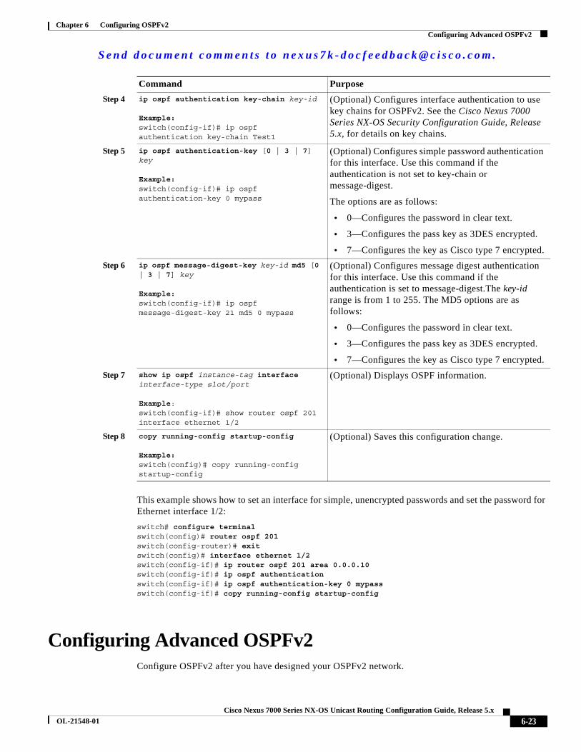
This example shows how to set an interface for simple, unencrypted passwords and set the password for Ethernet interface 1/2:
switch# configure terminalswitch(config)# router ospf 201switch(config-router)# exitswitch(config)# interface ethernet 1/2switch(config-if)# ip router ospf 201 area 0.0.0.10switch(config-if)# ip ospf authentication switch(config-if)# ip ospf authentication-key 0 mypassswitch(config-if)# copy running-config startup-config
Configuring Advanced OSPFv2Configure OSPFv2 after you have designed your OSPFv2 network.
Step 4 ip ospf authentication key-chain key-id
Example:switch(config-if)# ip ospf authentication key-chain Test1
(Optional) Configures interface authentication to use key chains for OSPFv2. See the Cisco Nexus 7000 Series NX-OS Security Configuration Guide, Release 5.x, for details on key chains.
Step 5 ip ospf authentication-key [0 | 3 | 7] key
Example:switch(config-if)# ip ospf authentication-key 0 mypass
(Optional) Configures simple password authentication for this interface. Use this command if the authentication is not set to key-chain or message-digest.
The options are as follows:
• 0—Configures the password in clear text.
• 3—Configures the pass key as 3DES encrypted.
• 7—Configures the key as Cisco type 7 encrypted.
Step 6 ip ospf message-digest-key key-id md5 [0 | 3 | 7] key
Example:switch(config-if)# ip ospf message-digest-key 21 md5 0 mypass
(Optional) Configures message digest authentication for this interface. Use this command if the authentication is set to message-digest.The key-id range is from 1 to 255. The MD5 options are as follows:
• 0—Configures the password in clear text.
• 3—Configures the pass key as 3DES encrypted.
• 7—Configures the key as Cisco type 7 encrypted.
Step 7 show ip ospf instance-tag interface interface-type slot/port
Example:switch(config-if)# show router ospf 201 interface ethernet 1/2
(Optional) Displays OSPF information.
Step 8 copy running-config startup-config
Example:switch(config)# copy running-config startup-config
(Optional) Saves this configuration change.
Command Purpose

S e n d d o c u m e n t c o m m e n t s t o n e x u s 7 k - d o c f e e d b a c k @ c i s c o . c o m .
6-24Cisco Nexus 7000 Series NX-OS Unicast Routing Configuration Guide, Release 5.x
OL-21548-01
Chapter 6 Configuring OSPFv2Configuring Advanced OSPFv2
This section includes the following topics:
• Configuring Filter Lists for Border Routers, page 6-24
• Configuring Stub Areas, page 6-25
• Configuring a Totally Stubby Area, page 6-27
• Configuring NSSA, page 6-27
• Configuring Virtual Links, page 6-29
• Configuring Redistribution, page 6-31
• Limiting the Number of Redistributed Routes, page 6-33
• Configuring Route Summarization, page 6-35
• Configuring Stub Route Advertisements, page 6-36
• Modifying the Default Timers, page 6-37
• Configuring Graceful Restart, page 6-40
• Restarting an OSPFv2 Instance, page 6-41
Configuring Filter Lists for Border Routers
You can separate your OSPFv2 domain into a series of areas that contain related networks. All areas must connect to the backbone area through an area border router (ABR). OSPFv2 domains can connect to external domains through an autonomous system border router (ASBR). See the “Areas” section on page 6-4.
ABRs have the following optional configuration parameters:
• Area range—Configures route summarization between areas. See the “Configuring Route Summarization” section on page 6-35.
• Filter list—Filters the Network Summary (type 3) LSAs that are allowed in from an external area.
ASBRs also support filter lists.
BEFORE YOU BEGIN
Ensure that you have enabled the OSPF feature (see the “Enabling OSPFv2” section on page 6-14).
Create the route map that the filter list uses to filter IP prefixes in incoming or outgoing Network Summary (type 3) LSAs. See Chapter 16, “Configuring Route Policy Manager.”
Ensure that you are in the correct VDC (or use the switchto vdc command).
SUMMARY STEPS
1. configure terminal
2. router ospf instance-tag
3. area area-id filter-list route-map map-name {in | out}
4. (Optional) show ip ospf policy statistics area id filter-list {in | out}
5. (Optional) copy running-config startup-config

S e n d d o c u m e n t c o m m e n t s t o n e x u s 7 k - d o c f e e d b a c k @ c i s c o . c o m .
6-25Cisco Nexus 7000 Series NX-OS Unicast Routing Configuration Guide, Release 5.x
OL-21548-01
Chapter 6 Configuring OSPFv2Configuring Advanced OSPFv2
DETAILED STEPS
This example shows how to configure a filter list in area 0.0.0.10:
switch# configure terminalswitch(config)# router ospf 201switch(config-router)# area 0.0.0.10 filter-list route-map FilterLSAs inswitch(config-router)# copy running-config startup-config
Configuring Stub Areas
You can configure a stub area for part of an OSPFv2 domain where external traffic is not necessary. Stub areas block AS External (type 5) LSAs and limit unnecessary routing to and from selected networks. See the “Stub Area” section on page 6-8. You can optionally block all summary routes from going into the stub area.
BEFORE YOU BEGIN
Ensure that you have enabled the OSPF feature (see the “Enabling OSPFv2” section on page 6-14).
Ensure that there are no virtual links or ASBRs in the proposed stub area.
Ensure that you are in the correct VDC (or use the switchto vdc command).
Command Purpose
Step 1 configure terminal
Example:switch# configure terminalswitch(config)#
Enters configuration mode.
Step 2 router ospf instance-tag
Example:switch(config)# router ospf 201switch(config-router)#
Creates a new OSPFv2 instance with the configured instance tag.
Step 3 area area-id filter-list route-map map-name {in | out}
Example:switch(config-router)# area 0.0.0.10 filter-list route-map FilterLSAs in
Filters incoming or outgoing Network Summary (type 3) LSAs on an ABR.
Step 4 show ip ospf policy statistics area id filter-list {in | out}
Example:switch(config-if)# show ip ospf policy statistics area 0.0.0.10 filter-list in
(Optional) Displays OSPF policy information.
Step 5 copy running-config startup-config
Example:switch(config)# copy running-config startup-config
(Optional) Saves this configuration change.

S e n d d o c u m e n t c o m m e n t s t o n e x u s 7 k - d o c f e e d b a c k @ c i s c o . c o m .
6-26Cisco Nexus 7000 Series NX-OS Unicast Routing Configuration Guide, Release 5.x
OL-21548-01
Chapter 6 Configuring OSPFv2Configuring Advanced OSPFv2
SUMMARY STEPS
1. configure terminal
2. router ospf instance-tag
3. area area-id stub
4. (Optional) area area-id default-cost cost
5. (Optional) show ip ospf instance-tag
6. (Optional) copy running-config startup-config
DETAILED STEPS
This example shows how to create a stub area:
switch# configure terminalswitch(config)# router ospf 201switch(config-router)# area 0.0.0.10 stub switch(config-router)# copy running-config startup-config
Command Purpose
Step 1 configure terminal
Example:switch# configure terminalswitch(config)#
Enters configuration mode.
Step 2 router ospf instance-tag
Example:switch(config)# router ospf 201switch(config-router)#
Creates a new OSPFv2 instance with the configured instance tag.
Step 3 area area-id stub
Example:switch(config-router)# area 0.0.0.10 stub
Creates this area as a stub area.
Step 4 area area-id default-cost cost
Example:switch(config-router)# area 0.0.0.10 default-cost 25
(Optional) Sets the cost metric for the default summary route sent into this stub area. The range is from 0 to 16777215. The default is 1.
Step 5 show ip ospf instance-tag
Example:switch(config-if)# show ip ospf 201
(Optional) Displays OSPF information.
Step 6 copy running-config startup-config
Example:switch(config)# copy running-config startup-config
(Optional) Saves this configuration change.
S e n d d o c u m e n t c o m m e n t s t o n e x u s 7 k - d o c f e e d b a c k @ c i s c o . c o m .
6-27Cisco Nexus 7000 Series NX-OS Unicast Routing Configuration Guide, Release 5.x
OL-21548-01
Chapter 6 Configuring OSPFv2Configuring Advanced OSPFv2
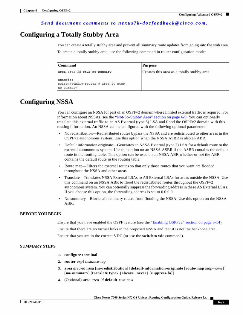
Configuring a Totally Stubby Area
You can create a totally stubby area and prevent all summary route updates from going into the stub area.
To create a totally stubby area, use the following command in router configuration mode:
Configuring NSSA
You can configure an NSSA for part of an OSPFv2 domain where limited external traffic is required. For information about NSSAs, see the “Not-So-Stubby Area” section on page 6-9. You can optionally translate this external traffic to an AS External (type 5) LSA and flood the OSPFv2 domain with this routing information. An NSSA can be configured with the following optional parameters:
• No redistribution—Redistributed routes bypass the NSSA and are redistributed to other areas in the OSPFv2 autonomous system. Use this option when the NSSA ASBR is also an ABR.
• Default information originate—Generates an NSSA External (type 7) LSA for a default route to the external autonomous system. Use this option on an NSSA ASBR if the ASBR contains the default route in the routing table. This option can be used on an NSSA ABR whether or not the ABR contains the default route in the routing table.
• Route map—Filters the external routes so that only those routes that you want are flooded throughout the NSSA and other areas.
• Translate—Translates NSSA External LSAs to AS External LSAs for areas outside the NSSA. Use this command on an NSSA ABR to flood the redistributed routes throughout the OSPFv2 autonomous system. You can optionally suppress the forwarding address in these AS External LSAs. If you choose this option, the forwarding address is set to 0.0.0.0.
• No summary—Blocks all summary routes from flooding the NSSA. Use this option on the NSSA ABR.
BEFORE YOU BEGIN
Ensure that you have enabled the OSPF feature (see the “Enabling OSPFv2” section on page 6-14).
Ensure that there are no virtual links in the proposed NSSA and that it is not the backbone area.
Ensure that you are in the correct VDC (or use the switchto vdc command).
SUMMARY STEPS
1. configure terminal
2. router ospf instance-tag
3. area area-id nssa [no-redistribution] [default-information-originate [route-map map-name]] [no-summary] [translate type7 {always | never} [suppress-fa]]
4. (Optional) area area-id default-cost cost
Command Purpose
area area-id stub no-summary
Example:switch(config-router)# area 20 stub no-summary
Creates this area as a totally stubby area.
S e n d d o c u m e n t c o m m e n t s t o n e x u s 7 k - d o c f e e d b a c k @ c i s c o . c o m .
6-28Cisco Nexus 7000 Series NX-OS Unicast Routing Configuration Guide, Release 5.x
OL-21548-01
Chapter 6 Configuring OSPFv2Configuring Advanced OSPFv2
5. (Optional) show ip ospf instance-tag
6. (Optional) copy running-config startup-config
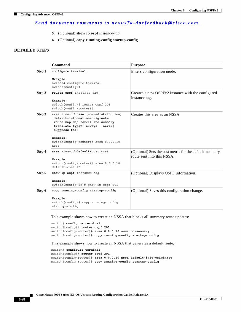
DETAILED STEPS
This example shows how to create an NSSA that blocks all summary route updates:
switch# configure terminalswitch(config)# router ospf 201switch(config-router)# area 0.0.0.10 nssa no-summaryswitch(config-router)# copy running-config startup-config
This example shows how to create an NSSA that generates a default route:
switch# configure terminalswitch(config)# router ospf 201switch(config-router)# area 0.0.0.10 nssa default-info-originateswitch(config-router)# copy running-config startup-config
Command Purpose
Step 1 configure terminal
Example:switch# configure terminalswitch(config)#
Enters configuration mode.
Step 2 router ospf instance-tag
Example:switch(config)# router ospf 201switch(config-router)#
Creates a new OSPFv2 instance with the configured instance tag.
Step 3 area area-id nssa [no-redistribution] [default-information-originate [route-map map-name]] [no-summary] [translate type7 {always | never} [suppress-fa]]
Example:switch(config-router)# area 0.0.0.10 nssa
Creates this area as an NSSA.
Step 4 area area-id default-cost cost
Example:switch(config-router)# area 0.0.0.10 default-cost 25
(Optional) Sets the cost metric for the default summary route sent into this NSSA.
Step 5 show ip ospf instance-tag
Example:switch(config-if)# show ip ospf 201
(Optional) Displays OSPF information.
Step 6 copy running-config startup-config
Example:switch(config)# copy running-config startup-config
(Optional) Saves this configuration change.
S e n d d o c u m e n t c o m m e n t s t o n e x u s 7 k - d o c f e e d b a c k @ c i s c o . c o m .
6-29Cisco Nexus 7000 Series NX-OS Unicast Routing Configuration Guide, Release 5.x
OL-21548-01
Chapter 6 Configuring OSPFv2Configuring Advanced OSPFv2
This example shows how to create an NSSA that filters external routes and blocks all summary route updates:
switch# configure terminalswitch(config)# router ospf 201switch(config-router)# area 0.0.0.10 nssa route-map ExternalFilter no-summaryswitch(config-router)# copy running-config startup-config
This example shows how to create an NSSA that always translates NSSA External (type 5) LSAs to AS External (type 7) LSAs:
switch# configure terminalswitch(config)# router ospf 201switch(config-router)# area 0.0.0.10 nssa translate type 7 alwaysswitch(config-router)# copy running-config startup-config
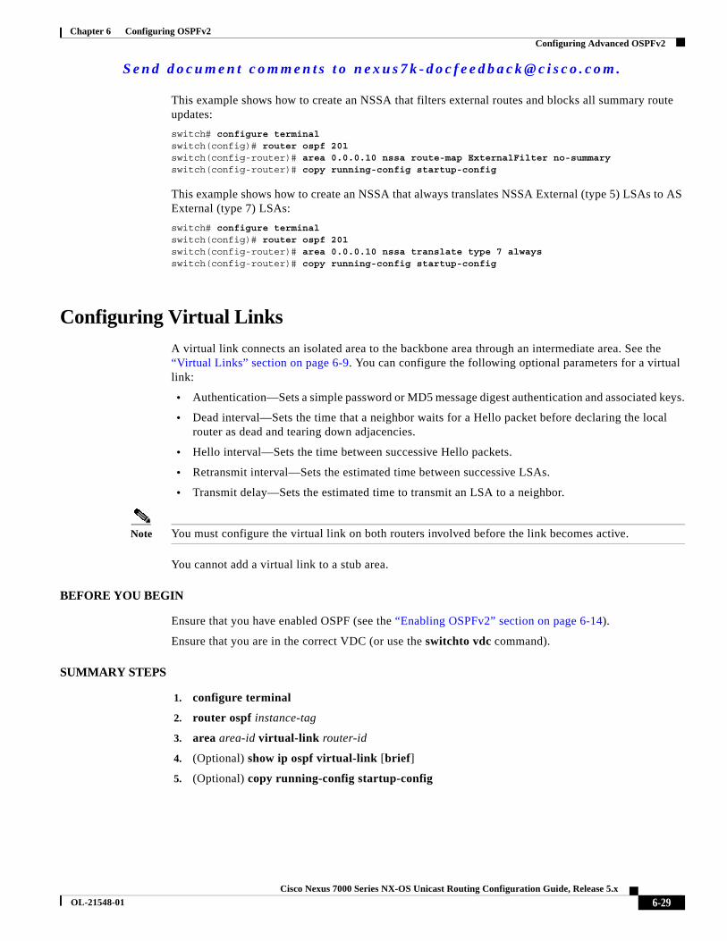
Configuring Virtual Links
A virtual link connects an isolated area to the backbone area through an intermediate area. See the “Virtual Links” section on page 6-9. You can configure the following optional parameters for a virtual link:
• Authentication—Sets a simple password or MD5 message digest authentication and associated keys.
• Dead interval—Sets the time that a neighbor waits for a Hello packet before declaring the local router as dead and tearing down adjacencies.
• Hello interval—Sets the time between successive Hello packets.
• Retransmit interval—Sets the estimated time between successive LSAs.
• Transmit delay—Sets the estimated time to transmit an LSA to a neighbor.
Note You must configure the virtual link on both routers involved before the link becomes active.
You cannot add a virtual link to a stub area.
BEFORE YOU BEGIN
Ensure that you have enabled OSPF (see the “Enabling OSPFv2” section on page 6-14).
Ensure that you are in the correct VDC (or use the switchto vdc command).
SUMMARY STEPS
1. configure terminal
2. router ospf instance-tag
3. area area-id virtual-link router-id
4. (Optional) show ip ospf virtual-link [brief]
5. (Optional) copy running-config startup-config

S e n d d o c u m e n t c o m m e n t s t o n e x u s 7 k - d o c f e e d b a c k @ c i s c o . c o m .
6-30Cisco Nexus 7000 Series NX-OS Unicast Routing Configuration Guide, Release 5.x
OL-21548-01
Chapter 6 Configuring OSPFv2Configuring Advanced OSPFv2
DETAILED STEPS
You can configure the following optional commands in virtual link configuration mode:
Command Purpose
Step 1 configure terminal
Example:switch# configure terminalswitch(config)#
Enters configuration mode.
Step 2 router ospf instance-tag
Example:switch(config)# router ospf 201switch(config-router)#
Creates a new OSPFv2 instance with the configured instance tag.
Step 3 area area-id virtual-link router-id
Example:switch(config-router)# area 0.0.0.10 virtual-link 10.1.2.3switch(config-router-vlink)#
Creates one end of a virtual link to a remote router. You must create the virtual link on that remote router to complete the link.
Step 4 show ip ospf virtual-link [brief]
Example:switch(config-router-vlink)# show ip ospf virtual-link
(Optional) Displays OSPF virtual link information.
Step 5 copy running-config startup-config
Example:switch(config-router-vlink)# copy running-config startup-config
(Optional) Saves this configuration change.
Command Purpose
authentication [key-chain key-id | message-digest | null]
Example:switch(config-router-vlink)# authentication message-digest
(Optional) Overrides area-based authentication for this virtual link.
authentication-key [0 | 3] key
Example:switch(config-router-vlink)# authentication-key 0 mypass
(Optional) Configures a simple password for this virtual link. Use this command if the authentication is not set to key-chain or message-digest. 0 configures the password in clear text. 3 configures the password as 3DES encrypted.
dead-interval seconds
Example:switch(config-router-vlink)# dead-interval 50
(Optional) Configures the OSPFv2 dead interval, in seconds. The range is from 1 to 65535. The default is four times the hello interval, in seconds.
hello-interval seconds
Example:switch(config-router-vlink)# hello-interval 25
(Optional) Configures the OSPFv2 hello interval, in seconds. The range is from 1 to 65535. The default is 10 seconds.

S e n d d o c u m e n t c o m m e n t s t o n e x u s 7 k - d o c f e e d b a c k @ c i s c o . c o m .
6-31Cisco Nexus 7000 Series NX-OS Unicast Routing Configuration Guide, Release 5.x
OL-21548-01
Chapter 6 Configuring OSPFv2Configuring Advanced OSPFv2
This example shows how to create a simple virtual link between two ABRs.
The configuration for ABR 1 (router ID 27.0.0.55) is as follows:
switch# configure terminalswitch(config)# router ospf 201switch(config-router)# area 0.0.0.10 virtual-link 10.1.2.3switch(config-router)# copy running-config startup-config
The configuration for ABR 2 (Router ID 10.1.2.3) is as follows:
switch# configure terminalswitch(config)# router ospf 101switch(config-router)# area 0.0.0.10 virtual-link 27.0.0.55switch(config-router)# copy running-config startup-config
Configuring Redistribution
You can redistribute routes learned from other routing protocols into an OSPFv2 autonomous system through the ASBR.
You can configure the following optional parameters for route redistribution in OSPF:
• Default information originate—Generates an AS External (type 5) LSA for a default route to the external autonomous system.
Note Default information originate ignores match statements in the optional route map.
• Default metric—Sets all redistributed routes to the same cost metric.
Note If you redistribute static routes, Cisco NX-OS also redistributes the default static route.
BEFORE YOU BEGIN
Ensure that you have enabled OSPF (see the “Enabling OSPFv2” section on page 6-14).
message-digest-key key-id md5 [0 | 3] key
Example:switch(config-router-vlink)#message-digest-key 21 md5 0 mypass
(Optional) Configures message digest authentication for this virtual link. Use this command if the authentication is set to message-digest. 0 configures the password in cleartext. 3 configures the pass key as 3DES encrypted.
retransmit-interval seconds
Example:switch(config-router-vlink)# retransmit-interval 50
(Optional) Configures the OSPFv2 retransmit interval, in seconds. The range is from 1 to 65535. The default is 5.
transmit-delay seconds
Example:switch(config-router-vlink)# transmit-delay 2
(Optional) Configures the OSPFv2 transmit-delay, in seconds. The range is from 1 to 450. The default is 1.
Command Purpose

S e n d d o c u m e n t c o m m e n t s t o n e x u s 7 k - d o c f e e d b a c k @ c i s c o . c o m .
6-32Cisco Nexus 7000 Series NX-OS Unicast Routing Configuration Guide, Release 5.x
OL-21548-01
Chapter 6 Configuring OSPFv2Configuring Advanced OSPFv2
Create the necessary route maps used for redistribution.
Ensure that you are in the correct VDC (or use the switchto vdc command).
SUMMARY STEPS
1. configure terminal
2. router ospf instance-tag
3. redistribute {bgp id | direct | eigrp id | isis id | ospf id | rip id | static} route-map map-name
4. default-information originate [always] [route-map map-name]
5. default-metric cost
6. (Optional) copy running-config startup-config
DETAILED STEPS
Command Purpose
Step 1 configure terminal
Example:switch# configure terminalswitch(config)#
Enters configuration mode.
Step 2 router ospf instance-tag
Example:switch(config)# router ospf 201switch(config-router)#
Creates a new OSPFv2 instance with the configured instance tag.
Step 3 redistribute {bgp id | direct | eigrp id | isis id | ospf id | rip id | static} route-map map-name
Example:switch(config-router)# redistribute bgp route-map FilterExternalBGP
Redistributes the selected protocol into OSPF through the configured route map.
Note If you redistribute static routes, Cisco NX-OS also redistributes the default static route.
Step 4 default-information originate [always] [route-map map-name]
Example:switch(config-router)# default-information-originate route-map DefaultRouteFilter
Creates a default route into this OSPF domain if the default route exists in the RIB. Use the following optional keywords:
• always —Always generate the default route of 0.0.0. even if the route does not exist in the RIB.
• route-map—Generate the default route if the route map returns true.
Note This command ignores match statements in the route map.
S e n d d o c u m e n t c o m m e n t s t o n e x u s 7 k - d o c f e e d b a c k @ c i s c o . c o m .
6-33Cisco Nexus 7000 Series NX-OS Unicast Routing Configuration Guide, Release 5.x
OL-21548-01
Chapter 6 Configuring OSPFv2Configuring Advanced OSPFv2
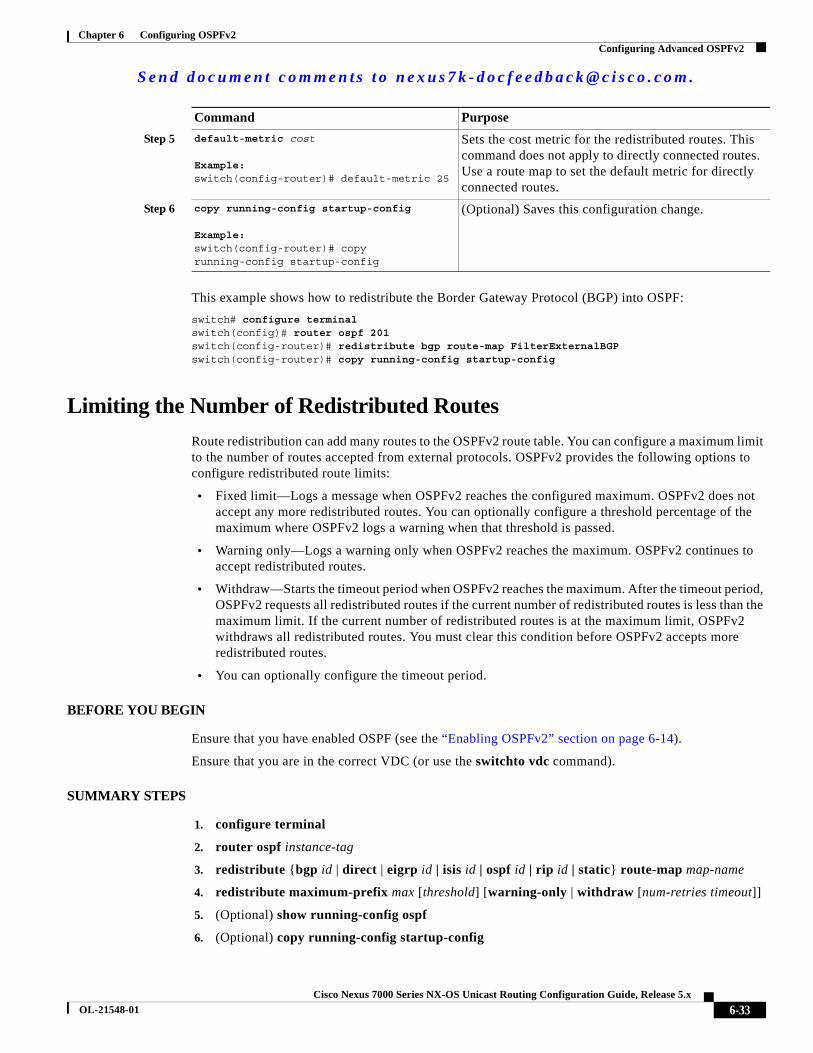
This example shows how to redistribute the Border Gateway Protocol (BGP) into OSPF:
switch# configure terminalswitch(config)# router ospf 201switch(config-router)# redistribute bgp route-map FilterExternalBGPswitch(config-router)# copy running-config startup-config
Limiting the Number of Redistributed Routes
Route redistribution can add many routes to the OSPFv2 route table. You can configure a maximum limit to the number of routes accepted from external protocols. OSPFv2 provides the following options to configure redistributed route limits:
• Fixed limit—Logs a message when OSPFv2 reaches the configured maximum. OSPFv2 does not accept any more redistributed routes. You can optionally configure a threshold percentage of the maximum where OSPFv2 logs a warning when that threshold is passed.
• Warning only—Logs a warning only when OSPFv2 reaches the maximum. OSPFv2 continues to accept redistributed routes.
• Withdraw—Starts the timeout period when OSPFv2 reaches the maximum. After the timeout period, OSPFv2 requests all redistributed routes if the current number of redistributed routes is less than the maximum limit. If the current number of redistributed routes is at the maximum limit, OSPFv2 withdraws all redistributed routes. You must clear this condition before OSPFv2 accepts more redistributed routes.
• You can optionally configure the timeout period.
BEFORE YOU BEGIN
Ensure that you have enabled OSPF (see the “Enabling OSPFv2” section on page 6-14).
Ensure that you are in the correct VDC (or use the switchto vdc command).
SUMMARY STEPS
1. configure terminal
2. router ospf instance-tag
3. redistribute {bgp id | direct | eigrp id | isis id | ospf id | rip id | static} route-map map-name
4. redistribute maximum-prefix max [threshold] [warning-only | withdraw [num-retries timeout]]
5. (Optional) show running-config ospf
6. (Optional) copy running-config startup-config
Step 5 default-metric cost
Example:switch(config-router)# default-metric 25
Sets the cost metric for the redistributed routes. This command does not apply to directly connected routes. Use a route map to set the default metric for directly connected routes.
Step 6 copy running-config startup-config
Example:switch(config-router)# copy running-config startup-config
(Optional) Saves this configuration change.
Command Purpose

S e n d d o c u m e n t c o m m e n t s t o n e x u s 7 k - d o c f e e d b a c k @ c i s c o . c o m .
6-34Cisco Nexus 7000 Series NX-OS Unicast Routing Configuration Guide, Release 5.x
OL-21548-01
Chapter 6 Configuring OSPFv2Configuring Advanced OSPFv2
DETAILED STEPS
This example shows how to limit the number of redistributed routes into OSPF:
switch# configure terminalswitch(config)# router ospf 201switch(config-router)# redistribute bgp route-map FilterExternalBGPswitch(config-router)# redistribute maximum-prefix 1000 75
Command Purpose
Step 1 configure terminal
Example:switch# configure terminalswitch(config)#
Enters configuration mode.
Step 2 router ospf instance-tag
Example:switch(config)# router ospf 201switch(config-router)#
Creates a new OSPFv2 instance with the configured instance tag.
Step 3 redistribute {bgp id | direct | eigrp id | isis id | ospf id | rip id | static} route-map map-name
Example:switch(config-router)# redistribute bgp route-map FilterExternalBGP
Redistributes the selected protocol into OSPF through the configured route map.
Step 4 redistribute maximum-prefix max [threshold] [warning-only | withdraw [num-retries timeout]]
Example:switch(config-router)# redistribute maximum-prefix 1000 75 warning-only
Specifies a maximum number of prefixes that OSPFv2 distributes. The range is from 0 to 65536. Optionally specifies the following:
• threshold—Percent of maximum prefixes that trigger a warning message.
• warning-only—Logs an warning message when the maximum number of prefixes is exceeded.
• withdraw—Withdraws all redistributed routes. Optionally tries to retrieve the redistributed routes. The num-retries range is from 1 to 12. The timeout is 60 to 600 seconds. The default is 300 seconds. Use the clear ip ospf redistribution command if all routes are withdrawn.
Step 5 show running-config ospf
Example:switch(config-router)# show running-config ospf
(Optional) Displays the OSPFv2 configuration.
Step 6 copy running-config startup-config
Example:switch(config-router)# copy running-config startup-config
(Optional) Saves this configuration change.

S e n d d o c u m e n t c o m m e n t s t o n e x u s 7 k - d o c f e e d b a c k @ c i s c o . c o m .
6-35Cisco Nexus 7000 Series NX-OS Unicast Routing Configuration Guide, Release 5.x
OL-21548-01
Chapter 6 Configuring OSPFv2Configuring Advanced OSPFv2
Configuring Route Summarization
You can configure route summarization for inter-area routes by configuring an address range that is summarized. You can also configure route summarization for external, redistributed routes by configuring a summary address for those routes on an ASBR. For more information, see the “Route Summarization” section on page 6-10.
BEFORE YOU BEGIN
Ensure that you have enabled OSPF (see the “Enabling OSPFv2” section on page 6-14).
Ensure that you are in the correct VDC (or use the switchto vdc command).
SUMMARY STEPS
1. configure terminal
2. router ospf instance-tag
3. area area-id range ip-prefix/length [no-advertise] [cost cost]
or
4. summary-address ip-prefix/length [no-advertise | tag tag-id]
5. (Optional) show ip ospf summary-address
6. (Optional) copy running-config startup-config
DETAILED STEPS
Command Purpose
Step 1 configure terminal
Example:switch# configure terminalswitch(config)#
Enters configuration mode.
Step 2 router ospf instance-tag
Example:switch(config)# router ospf 201switch(config-router)#
Creates a new OSPFv2 instance with the configured instance tag.
Step 3 area area-id range ip-prefix/length [no-advertise] [cost cost]
Example:switch(config-router)# area 0.0.0.10 range 10.3.0.0/16
Creates a summary address on an ABR for a range of addresses and optionally does not advertise this summary address in a Network Summary (type 3) LSA. The cost range is from 0 to 16777215.
Step 4 summary-address ip-prefix/length [no-advertise | tag tag]
Example:switch(config-router)# summary-address 10.5.0.0/16 tag 2
Creates a summary address on an ASBR for a range of addresses and optionally assigns a tag for this summary address that can be used for redistribution with route maps.
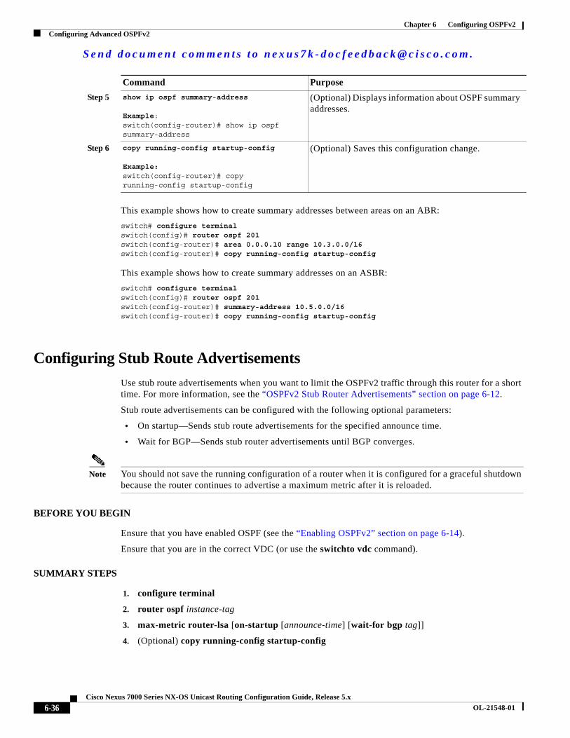
S e n d d o c u m e n t c o m m e n t s t o n e x u s 7 k - d o c f e e d b a c k @ c i s c o . c o m .
6-36Cisco Nexus 7000 Series NX-OS Unicast Routing Configuration Guide, Release 5.x
OL-21548-01
Chapter 6 Configuring OSPFv2Configuring Advanced OSPFv2
This example shows how to create summary addresses between areas on an ABR:
switch# configure terminalswitch(config)# router ospf 201switch(config-router)# area 0.0.0.10 range 10.3.0.0/16switch(config-router)# copy running-config startup-config
This example shows how to create summary addresses on an ASBR:
switch# configure terminalswitch(config)# router ospf 201switch(config-router)# summary-address 10.5.0.0/16switch(config-router)# copy running-config startup-config
Configuring Stub Route Advertisements
Use stub route advertisements when you want to limit the OSPFv2 traffic through this router for a short time. For more information, see the “OSPFv2 Stub Router Advertisements” section on page 6-12.
Stub route advertisements can be configured with the following optional parameters:
• On startup—Sends stub route advertisements for the specified announce time.
• Wait for BGP—Sends stub router advertisements until BGP converges.
Note You should not save the running configuration of a router when it is configured for a graceful shutdown because the router continues to advertise a maximum metric after it is reloaded.
BEFORE YOU BEGIN
Ensure that you have enabled OSPF (see the “Enabling OSPFv2” section on page 6-14).
Ensure that you are in the correct VDC (or use the switchto vdc command).
SUMMARY STEPS
1. configure terminal
2. router ospf instance-tag
3. max-metric router-lsa [on-startup [announce-time] [wait-for bgp tag]]
4. (Optional) copy running-config startup-config
Step 5 show ip ospf summary-address
Example:switch(config-router)# show ip ospf summary-address
(Optional) Displays information about OSPF summary addresses.
Step 6 copy running-config startup-config
Example:switch(config-router)# copy running-config startup-config
(Optional) Saves this configuration change.
Command Purpose

S e n d d o c u m e n t c o m m e n t s t o n e x u s 7 k - d o c f e e d b a c k @ c i s c o . c o m .
6-37Cisco Nexus 7000 Series NX-OS Unicast Routing Configuration Guide, Release 5.x
OL-21548-01
Chapter 6 Configuring OSPFv2Configuring Advanced OSPFv2
DETAILED STEPS
This example shows how to enable the stub router advertisements on startup for the default 600 seconds:
switch# configure terminalswitch(config)# router ospf 201switch(config-router)# max-metric router-lsa on-startup switch(config-router)# copy running-config startup-config
Modifying the Default Timers
OSPFv2 includes a number of timers that control the behavior of protocol messages and shortest path first (SPF) calculations. OSPFv2 includes the following optional timer parameters:
• LSA arrival time—Sets the minimum interval allowed between LSAs that arrive from a neighbor. LSAs that arrive faster than this time are dropped.
• Pacing LSAs—Sets the interval at which LSAs are collected into a group and refreshed, checksummed, or aged. This timer controls how frequently LSA updates occur and optimizes how many are sent in an LSA update message (see the “Flooding and LSA Group Pacing” section on page 6-6).
• Throttle LSAs—Sets the rate limits for generating LSAs. This timer controls how frequently LSAs are generated after a topology change occurs.
• Throttle SPF calculation—Controls how frequently the SPF calculation is run.
At the interface level, you can also control the following timers:
• Retransmit interval—Sets the estimated time between successive LSAs.
• Transmit delay—Sets the estimated time to transmit an LSA to a neighbor.
See the “Configuring Networks in OSPFv2” section on page 6-18 for information about the hello interval and dead timer.
Command Purpose
Step 1 configure terminal
Example:switch# configure terminalswitch(config)#
Enters configuration mode.
Step 2 router ospf instance-tag
Example:switch(config)# router ospf 201switch(config-router)#
Creates a new OSPFv2 instance with the configured instance tag.
Step 3 max-metric router-lsa [on-startup [announce-time] [wait-for bgp tag]]Example:switch(config-router)# max-metric router-lsa
Configures OSPFv2 stub route advertisements.
Step 4 copy running-config startup-config
Example:switch(config-router)# copy running-config startup-config
(Optional) Saves this configuration change.

S e n d d o c u m e n t c o m m e n t s t o n e x u s 7 k - d o c f e e d b a c k @ c i s c o . c o m .
6-38Cisco Nexus 7000 Series NX-OS Unicast Routing Configuration Guide, Release 5.x
OL-21548-01
Chapter 6 Configuring OSPFv2Configuring Advanced OSPFv2
BEFORE YOU BEGIN
Ensure that you have enabled OSPF (see the “Enabling OSPFv2” section on page 6-14).
Ensure that you are in the correct VDC (or use the switchto vdc command).
SUMMARY STEPS
1. configure terminal
2. router ospf instance-tag
3. timers lsa-arrival msec
4. timers lsa-group-pacing seconds
5. timers throttle lsa start-time hold-interval max-time
6. timers throttle spf delay-time hold-time
7. interface type slot/port
8. ip ospf hello-interval seconds
9. ip ospf dead-interval seconds
10. ip ospf retransmit-interval seconds
11. ip ospf transmit-delay seconds
12. (Optional) show ip ospf
13. (Optional) copy running-config startup-config
DETAILED STEPS
Command Purpose
Step 1 configure terminal
Example:switch# configure terminalswitch(config)#
Enters configuration mode.
Step 2 router ospf instance-tag
Example:switch(config)# router ospf 201switch(config-router)#
Creates a new OSPFv2 instance with the configured instance tag.
Step 3 timers lsa-arrival msec
Example:switch(config-router)# timers lsa-arrival 2000
Sets the LSA arrival time in milliseconds. The range is from 10 to 600000. The default is 1000 milliseconds.
Step 4 timers lsa-group-pacing seconds
Example:switch(config-router)# timers lsa-group-pacing 200
Sets the interval in seconds for grouping LSAs. The range is from 1 to 1800. The default is 10 seconds.

S e n d d o c u m e n t c o m m e n t s t o n e x u s 7 k - d o c f e e d b a c k @ c i s c o . c o m .
6-39Cisco Nexus 7000 Series NX-OS Unicast Routing Configuration Guide, Release 5.x
OL-21548-01
Chapter 6 Configuring OSPFv2Configuring Advanced OSPFv2
Step 5 timers throttle lsa start-time hold-interval max-time
Example:switch(config-router)# timers throttle lsa 3000
Sets the rate limit in milliseconds for generating LSAs with the following timers:
start-time—The range is from 0 to 5000 milliseconds. The default value is 0 milliseconds.
hold-interval—The range is from 50 to 30,000 milliseconds. The default value is 5000 milliseconds.
max-time—The range is from 50 to 30,000 milliseconds. The default value is 5000 milliseconds.
Step 6 timers throttle spf delay-time hold-time max-wait
Example:switch(config-router)# timers throttle spf 3000 2000 4000
Sets the SPF best path schedule initial delay time and the minimum hold time in seconds between SPF best path calculations. The range is from 1 to 600000. The default is no delay time and a 5000-millisecond hold time.
Step 7 interface type slot/port
Example:switch(config)# interface ethernet 1/2switch(config-if)#
Enters interface configuration mode.
Step 8 ip ospf hello-interval seconds
Example:switch(config-if)# ip ospf hello-interval 30
Sets the hello interval for this interface. The range is from 1 to 65535. The default is 10.
Step 9 ip ospf dead-interval seconds
Example:switch(config-if)# ip ospf dead-interval 30
Sets the dead interval for this interface. The range is from 1 to 65535.
Step 10 ip ospf retransmit-interval seconds
Example:switch(config-if)# ip ospf retransmit-interval 30
Sets the estimated time in seconds between LSAs transmitted from this interface. The range is from 1 to 65535. The default is 5.
Step 11 ip ospf transmit-delay seconds
Example:switch(config-if)# ip ospf transmit-delay 600switch(config-if)#
Sets the estimated time in seconds to transmit an LSA to a neighbor. The range is from 1 to 450. The default is 1.
Step 12 show ip ospf
Example:switch(config-if)# show ip ospf
(Optional) Displays information about OSPF.
Step 13 copy running-config startup-config
Example:switch(config-if)# copy running-config startup-config
(Optional) Saves this configuration change.
Command Purpose
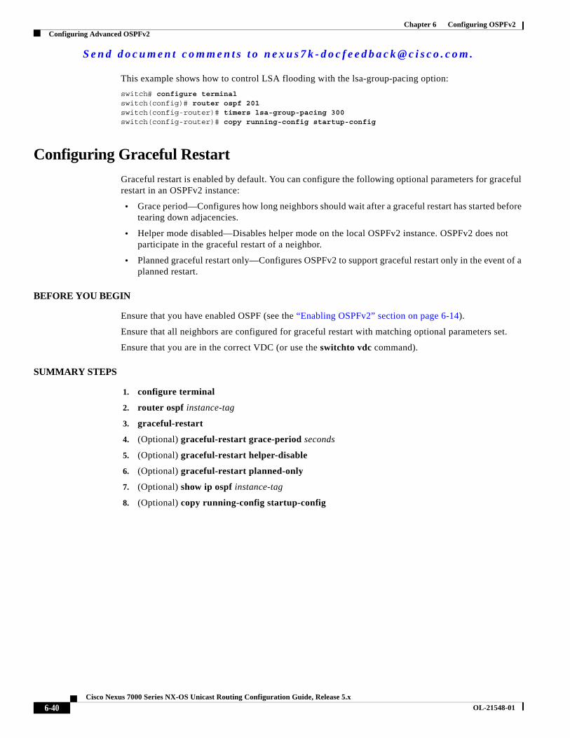
S e n d d o c u m e n t c o m m e n t s t o n e x u s 7 k - d o c f e e d b a c k @ c i s c o . c o m .
6-40Cisco Nexus 7000 Series NX-OS Unicast Routing Configuration Guide, Release 5.x
OL-21548-01
Chapter 6 Configuring OSPFv2Configuring Advanced OSPFv2
This example shows how to control LSA flooding with the lsa-group-pacing option:
switch# configure terminalswitch(config)# router ospf 201switch(config-router)# timers lsa-group-pacing 300switch(config-router)# copy running-config startup-config
Configuring Graceful Restart
Graceful restart is enabled by default. You can configure the following optional parameters for graceful restart in an OSPFv2 instance:
• Grace period—Configures how long neighbors should wait after a graceful restart has started before tearing down adjacencies.
• Helper mode disabled—Disables helper mode on the local OSPFv2 instance. OSPFv2 does not participate in the graceful restart of a neighbor.
• Planned graceful restart only—Configures OSPFv2 to support graceful restart only in the event of a planned restart.
BEFORE YOU BEGIN
Ensure that you have enabled OSPF (see the “Enabling OSPFv2” section on page 6-14).
Ensure that all neighbors are configured for graceful restart with matching optional parameters set.
Ensure that you are in the correct VDC (or use the switchto vdc command).
SUMMARY STEPS
1. configure terminal
2. router ospf instance-tag
3. graceful-restart
4. (Optional) graceful-restart grace-period seconds
5. (Optional) graceful-restart helper-disable
6. (Optional) graceful-restart planned-only
7. (Optional) show ip ospf instance-tag
8. (Optional) copy running-config startup-config
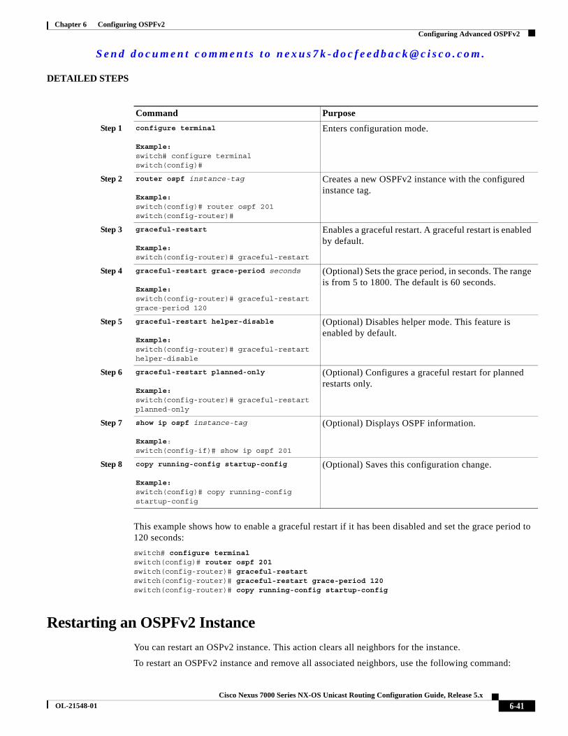
S e n d d o c u m e n t c o m m e n t s t o n e x u s 7 k - d o c f e e d b a c k @ c i s c o . c o m .
6-41Cisco Nexus 7000 Series NX-OS Unicast Routing Configuration Guide, Release 5.x
OL-21548-01
Chapter 6 Configuring OSPFv2Configuring Advanced OSPFv2
DETAILED STEPS
This example shows how to enable a graceful restart if it has been disabled and set the grace period to 120 seconds:
switch# configure terminalswitch(config)# router ospf 201switch(config-router)# graceful-restartswitch(config-router)# graceful-restart grace-period 120switch(config-router)# copy running-config startup-config
Restarting an OSPFv2 Instance
You can restart an OSPv2 instance. This action clears all neighbors for the instance.
To restart an OSPFv2 instance and remove all associated neighbors, use the following command:
Command Purpose
Step 1 configure terminal
Example:switch# configure terminalswitch(config)#
Enters configuration mode.
Step 2 router ospf instance-tag
Example:switch(config)# router ospf 201switch(config-router)#
Creates a new OSPFv2 instance with the configured instance tag.
Step 3 graceful-restart
Example:switch(config-router)# graceful-restart
Enables a graceful restart. A graceful restart is enabled by default.
Step 4 graceful-restart grace-period seconds
Example:switch(config-router)# graceful-restart grace-period 120
(Optional) Sets the grace period, in seconds. The range is from 5 to 1800. The default is 60 seconds.
Step 5 graceful-restart helper-disable
Example:switch(config-router)# graceful-restart helper-disable
(Optional) Disables helper mode. This feature is enabled by default.
Step 6 graceful-restart planned-only
Example:switch(config-router)# graceful-restart planned-only
(Optional) Configures a graceful restart for planned restarts only.
Step 7 show ip ospf instance-tag
Example:switch(config-if)# show ip ospf 201
(Optional) Displays OSPF information.
Step 8 copy running-config startup-config
Example:switch(config)# copy running-config startup-config
(Optional) Saves this configuration change.

S e n d d o c u m e n t c o m m e n t s t o n e x u s 7 k - d o c f e e d b a c k @ c i s c o . c o m .
6-42Cisco Nexus 7000 Series NX-OS Unicast Routing Configuration Guide, Release 5.x
OL-21548-01
Chapter 6 Configuring OSPFv2Configuring Advanced OSPFv2
Configuring OSPFv2 with Virtualization
You can configure multiple OSPFv2 instances in each VDC. You can also create multiple VRFs within each VDC and use the same or multiple OSPFv2 instances in each VRF. You assign an OSPFv2 interface to a VRF.
Note Configure all other parameters for an interface after you configure the VRF for an interface. Configuring a VRF for an interface deletes all the configuration for that interface.
BEFORE YOU BEGIN
Create the VDCs.
Ensure that you have enabled OSPF (see the “Enabling OSPFv2” section on page 6-14).
Ensure that you are in the correct VDC (or use the switchto vdc command).
SUMMARY STEPS
1. configure terminal
2. vrf context vrf_name
3. router ospf instance-tag
4. vrf vrf-name
5. (Optional) maximum-paths paths
6. interface interface-type slot/port
7. vrf member vrf-name
8. ip-address ip-prefix/length
9. router ospf instance-tag area area-id
10. (Optional) copy running-config startup-config
Command Purpose
restart ospf instance-tag
Example:switch(config)# restart ospf 201
Restarts the OSPFv2 instance and removes all neighbors.
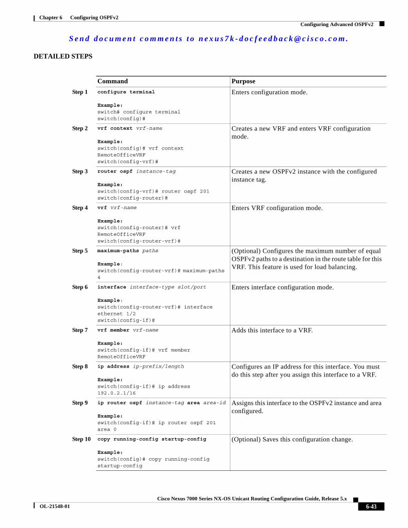
S e n d d o c u m e n t c o m m e n t s t o n e x u s 7 k - d o c f e e d b a c k @ c i s c o . c o m .
6-43Cisco Nexus 7000 Series NX-OS Unicast Routing Configuration Guide, Release 5.x
OL-21548-01
Chapter 6 Configuring OSPFv2Configuring Advanced OSPFv2
DETAILED STEPS
Command Purpose
Step 1 configure terminal
Example:switch# configure terminalswitch(config)#
Enters configuration mode.
Step 2 vrf context vrf-name
Example:switch(config)# vrf context RemoteOfficeVRFswitch(config-vrf)#
Creates a new VRF and enters VRF configuration mode.
Step 3 router ospf instance-tag
Example:switch(config-vrf)# router ospf 201switch(config-router)#
Creates a new OSPFv2 instance with the configured instance tag.
Step 4 vrf vrf-name
Example:switch(config-router)# vrf RemoteOfficeVRFswitch(config-router-vrf)#
Enters VRF configuration mode.
Step 5 maximum-paths paths
Example:switch(config-router-vrf)# maximum-paths 4
(Optional) Configures the maximum number of equal OSPFv2 paths to a destination in the route table for this VRF. This feature is used for load balancing.
Step 6 interface interface-type slot/port
Example:switch(config-router-vrf)# interface ethernet 1/2switch(config-if)#
Enters interface configuration mode.
Step 7 vrf member vrf-name
Example:switch(config-if)# vrf member RemoteOfficeVRF
Adds this interface to a VRF.
Step 8 ip address ip-prefix/length
Example:switch(config-if)# ip address 192.0.2.1/16
Configures an IP address for this interface. You must do this step after you assign this interface to a VRF.
Step 9 ip router ospf instance-tag area area-id
Example:switch(config-if)# ip router ospf 201 area 0
Assigns this interface to the OSPFv2 instance and area configured.
Step 10 copy running-config startup-config
Example:switch(config)# copy running-config startup-config
(Optional) Saves this configuration change.

S e n d d o c u m e n t c o m m e n t s t o n e x u s 7 k - d o c f e e d b a c k @ c i s c o . c o m .
6-44Cisco Nexus 7000 Series NX-OS Unicast Routing Configuration Guide, Release 5.x
OL-21548-01
Chapter 6 Configuring OSPFv2Verifying the OSPFv2 Configuration
This example shows how to create a VRF and add an interface to the VRF:
switch# configure terminalswitch(config)# vrf context NewVRFswitch(config)# router ospf 201switch(config)# interface ethernet 1/2switch(config-if)# vrf member NewVRFswitch(config-if)# ip address 192.0.2.1/16switch(config-if)# ip router ospf 201 area 0switch(config)# copy running-config startup-config
Verifying the OSPFv2 ConfigurationTo display the OSPFv2 configuration, perform one of the following tasks:
Command Purpose
show ip ospf Displays the OSPFv2 configuration.
show ip ospf border-routers [vrf {vrf-name | all | default | management}]
Displays the OSPFv2 border router configuration.
show ip ospf database [vrf {vrf-name | all | default | management}]
Displays the OSPFv2 link-state database summary.
show ip ospf interface number [vrf {vrf-name | all | default | management}]
Displays the OSPFv2 interface configuration.
show ip ospf lsa-content-changed-list neighbor-id interface-type number [vrf {vrf-name | all | default | management}]
Displays the OSPFv2 LSAs that have changed.
show ip ospf neighbors [neighbor-id] [detail] [interface-type number] [vrf {vrf-name | all | default | management}] [summary]
Displays the list of OSPFv2 neighbors.
show ip ospf request-list neighbor-id interface-type number [vrf {vrf-name | all | default | management}]
Displays the list of OSPFv2 link-state requests.
show ip ospf retransmission-list neighbor-id interface-type number [vrf {vrf-name | all | default | management}]
Displays the list of OSPFv2 link-state retransmissions.
show ip ospf route [ospf-route] [summary] [vrf {vrf-name | all | default | management}]
Displays the internal OSPFv2 routes.
show ip ospf summary-address [vrf {vrf-name | all | default | management}]
Displays information about the OSPFv2 summary addresses.
show ip ospf virtual-links [brief] [vrf {vrf-name | all | default | management}]
Displays information about OSPFv2 virtual links.
show ip ospf vrf {vrf-name | all | default | management}
Displays information about VRF-based OSPFv2 configuration.
show running-configuration ospf Displays the current running OSPFv2 configuration.

S e n d d o c u m e n t c o m m e n t s t o n e x u s 7 k - d o c f e e d b a c k @ c i s c o . c o m .
6-45Cisco Nexus 7000 Series NX-OS Unicast Routing Configuration Guide, Release 5.x
OL-21548-01
Chapter 6 Configuring OSPFv2Monitoring OSPFv2
Monitoring OSPFv2To display OSPFv2 statistics, use the following commands:
Configuration Examples for OSPFv2The following example shows how to configure OSPFv2:
feature ospfrouter ospf 201router-id 290.0.2.1
interface ethernet 1/2ip router ospf 201 area 0.0.0.10ip ospf authenticationip ospf authentication-key 0 mypass
OSPF RFC Compatibility Mode Example
The following example shows how to configure OSPF to be compatible with routers that comply with RFC 1583:
Note You must configure RFC 1583 compatibility on any VRF that connects to routers running only RFC1583 compatible OSPF.
switch#_configure terminalswitch(config)# feature ospfswitch(config)# router ospf Test1switch(config-router)# rfc1583compatibilityswitch(config-router)# vrf Aswitch(config-router-vrf)# rfc1583compatibility
Command Purpose
show ip ospf policy statistics area area-id filter-list {in | out} [vrf {vrf-name | all | default | management}]
Displays the OSPFv2 route policy statistics for an area.
show ip ospf policy statistics redistribute {bgp id | direct | eigrp id | isis id | ospf id | rip id | static} [vrf {vrf-name | all | default | management}]
Displays the OSPFv2 route policy statistics.
show ip ospf statistics [vrf {vrf-name | all | default | management}]
Displays the OSPFv2 event counters.
show ip ospf traffic [interface-type number] [vrf {vrf-name | all | default | management}]
Displays the OSPFv2 packet counters.

S e n d d o c u m e n t c o m m e n t s t o n e x u s 7 k - d o c f e e d b a c k @ c i s c o . c o m .
6-46Cisco Nexus 7000 Series NX-OS Unicast Routing Configuration Guide, Release 5.x
OL-21548-01
Chapter 6 Configuring OSPFv2Additional References
Additional ReferencesFor additional information related to implementing OSPF, see the following sections:
• Related Documents, page 6-46
• MIBs, page 6-46
Related Documents
MIBs
Feature History for OSPFv2Table 6-3 lists the release history for this feature.
Related Topic Document Title
OSPFv2 CLI commands Cisco Nexus 7000 Series NX-OS Unicast Routing Command Reference, Release 5.x
VDCs Cisco Nexus 7000 Series NX-OS Virtual Device Context Configuration Guide, Release 5.x
OSPFv3 for IPv6 networks Chapter 7, “Configuring OSPFv3”
Route maps Chapter 16, “Configuring Route Policy Manager”
MIBs MIBs Link
• OSPF-MIB
• OSPF-TRAP-MIB
To locate and download MIBs, go to the following URL:
http://www.cisco.com/public/sw-center/netmgmt/cmtk/mibs.shtml
Table 6-3 Feature History for IOSPFv2
Feature Name Releases Feature Information
Passive interface 5.2(1) Added support for setting the passive interface mode on all interfaces in the router or VRF.
BFD 5.0(2) Added support for BFD. See the Cisco Nexus 7000 Series NX-OS Interfaces Configuration Guide, Release 5.x, for more information.
OSPFv2 4.0(1) This feature was introduced.