lab troubleshooting basic single-area ospfv2 and ospfv3 lab...lab – troubleshooting basic...
TRANSCRIPT

© 2013 Cisco and/or its affiliates. All rights reserved. This document is Cisco Public. Page 1 of 12
Lab – Troubleshooting Basic Single-Area OSPFv2 and OSPFv3
Topology
Lab – Troubleshooting Basic Single-Area OSPFv2 and OSPFv3
© 2013 Cisco and/or its affiliates. All rights reserved. This document is Cisco Public. Page 2 of 12
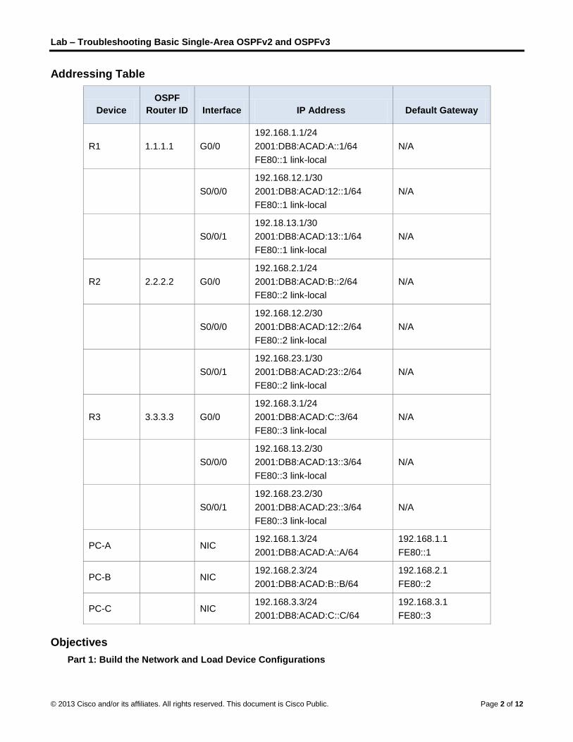
Addressing Table
Device
OSPF
Router ID Interface IP Address Default Gateway
R1 1.1.1.1 G0/0
192.168.1.1/24
2001:DB8:ACAD:A::1/64
FE80::1 link-local
N/A
S0/0/0
192.168.12.1/30
2001:DB8:ACAD:12::1/64
FE80::1 link-local
N/A
S0/0/1
192.18.13.1/30
2001:DB8:ACAD:13::1/64
FE80::1 link-local
N/A
R2 2.2.2.2 G0/0
192.168.2.1/24
2001:DB8:ACAD:B::2/64
FE80::2 link-local
N/A
S0/0/0
192.168.12.2/30
2001:DB8:ACAD:12::2/64
FE80::2 link-local
N/A
S0/0/1
192.168.23.1/30
2001:DB8:ACAD:23::2/64
FE80::2 link-local
N/A
R3 3.3.3.3 G0/0
192.168.3.1/24
2001:DB8:ACAD:C::3/64
FE80::3 link-local
N/A
S0/0/0
192.168.13.2/30
2001:DB8:ACAD:13::3/64
FE80::3 link-local
N/A
S0/0/1
192.168.23.2/30
2001:DB8:ACAD:23::3/64
FE80::3 link-local
N/A
PC-A NIC 192.168.1.3/24
2001:DB8:ACAD:A::A/64
192.168.1.1
FE80::1
PC-B NIC 192.168.2.3/24
2001:DB8:ACAD:B::B/64
192.168.2.1
FE80::2
PC-C NIC 192.168.3.3/24
2001:DB8:ACAD:C::C/64
192.168.3.1
FE80::3
Objectives
Part 1: Build the Network and Load Device Configurations
Lab – Troubleshooting Basic Single-Area OSPFv2 and OSPFv3
© 2013 Cisco and/or its affiliates. All rights reserved. This document is Cisco Public. Page 3 of 12
Part 2: Troubleshoot Layer 3 Connectivity
Part 3: Troubleshoot OSPFv2
Part 4: Troubleshoot OSPFv3
Background / Scenario
Open Shortest Path First (OSPF) is a link-state routing protocol for IP networks. OSPFv2 is defined for IPv4 networks, and OSPFv3 is defined for IPv6 networks. OSPFv2 and OSPFv3 are completely isolated routing protocols, changes in OSPFv2 do not affect OSPFv3 routing, and vice versa.
In this lab, a single-area OSPF network running OSPFv2 and OSPFv3 is experiencing problems. You have been assigned to find the problems with the network and correct them.
Note: The routers used with CCNA hands-on labs are Cisco 1941 Integrated Services Routers (ISRs) with Cisco IOS Release 15.2(4)M3 (universalk9 image). Other routers and Cisco IOS versions can be used. Depending on the model and Cisco IOS version, the commands available and output produced might vary from what is shown in the labs. Refer to the Router Interface Summary Table at the end of this lab for the correct interface identifiers.
Note: Make sure that the routers have been erased and have no startup configurations. If you are unsure, contact your instructor.
Required Resources
3 Routers (Cisco 1941 with Cisco IOS Release 15.2(4)M3 universal image or comparable)
3 PCs (Windows 7, Vista, or XP with terminal emulation program, such as Tera Term)
Console cables to configure the Cisco IOS devices via the console ports
Ethernet and serial cables as shown in the topology
Part 1: Build the Network and Load Device Configurations
In Part 1, you will set up the network topology and configure basic settings on the PC hosts and routers.
Step 1: Cable the network as shown in the topology.
Step 2: Configure PC hosts.
Step 3: Load router configurations.
Load the following configurations into the appropriate router. All routers have the same passwords. The privileged EXEC password is cisco. The password for console and vty access is class.
Router R1 Configuration:
conf t
service password-encryption
no ip domain lookup
hostname R1
enable secret class
line con 0
logging synchronous
password cisco
login
Lab – Troubleshooting Basic Single-Area OSPFv2 and OSPFv3
© 2013 Cisco and/or its affiliates. All rights reserved. This document is Cisco Public. Page 4 of 12
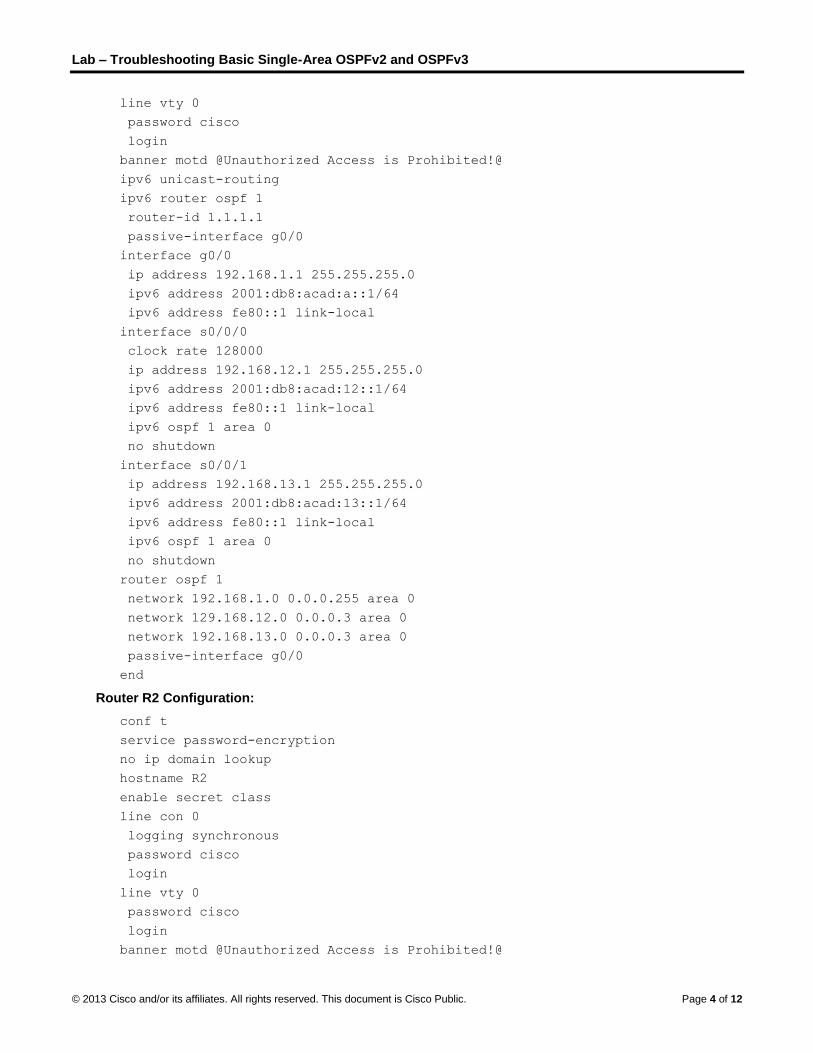
line vty 0
password cisco
login
banner motd @Unauthorized Access is Prohibited!@
ipv6 unicast-routing
ipv6 router ospf 1
router-id 1.1.1.1
passive-interface g0/0
interface g0/0
ip address 192.168.1.1 255.255.255.0
ipv6 address 2001:db8:acad:a::1/64
ipv6 address fe80::1 link-local
interface s0/0/0
clock rate 128000
ip address 192.168.12.1 255.255.255.0
ipv6 address 2001:db8:acad:12::1/64
ipv6 address fe80::1 link-local
ipv6 ospf 1 area 0
no shutdown
interface s0/0/1
ip address 192.168.13.1 255.255.255.0
ipv6 address 2001:db8:acad:13::1/64
ipv6 address fe80::1 link-local
ipv6 ospf 1 area 0
no shutdown
router ospf 1
network 192.168.1.0 0.0.0.255 area 0
network 129.168.12.0 0.0.0.3 area 0
network 192.168.13.0 0.0.0.3 area 0
passive-interface g0/0
end
Router R2 Configuration:
conf t
service password-encryption
no ip domain lookup
hostname R2
enable secret class
line con 0
logging synchronous
password cisco
login
line vty 0
password cisco
login
banner motd @Unauthorized Access is Prohibited!@
Lab – Troubleshooting Basic Single-Area OSPFv2 and OSPFv3
© 2013 Cisco and/or its affiliates. All rights reserved. This document is Cisco Public. Page 5 of 12
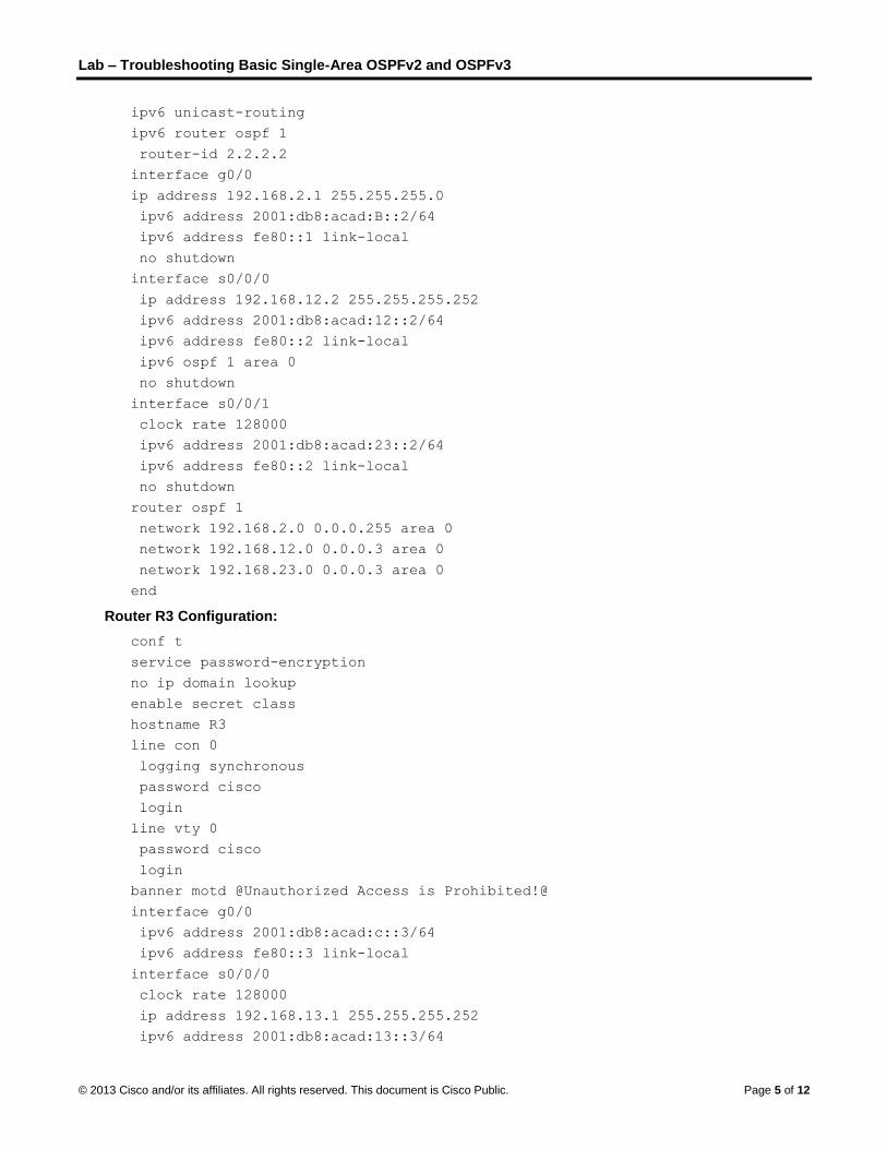
ipv6 unicast-routing
ipv6 router ospf 1
router-id 2.2.2.2
interface g0/0
ip address 192.168.2.1 255.255.255.0
ipv6 address 2001:db8:acad:B::2/64
ipv6 address fe80::1 link-local
no shutdown
interface s0/0/0
ip address 192.168.12.2 255.255.255.252
ipv6 address 2001:db8:acad:12::2/64
ipv6 address fe80::2 link-local
ipv6 ospf 1 area 0
no shutdown
interface s0/0/1
clock rate 128000
ipv6 address 2001:db8:acad:23::2/64
ipv6 address fe80::2 link-local
no shutdown
router ospf 1
network 192.168.2.0 0.0.0.255 area 0
network 192.168.12.0 0.0.0.3 area 0
network 192.168.23.0 0.0.0.3 area 0
end
Router R3 Configuration:
conf t
service password-encryption
no ip domain lookup
enable secret class
hostname R3
line con 0
logging synchronous
password cisco
login
line vty 0
password cisco
login
banner motd @Unauthorized Access is Prohibited!@
interface g0/0
ipv6 address 2001:db8:acad:c::3/64
ipv6 address fe80::3 link-local
interface s0/0/0
clock rate 128000
ip address 192.168.13.1 255.255.255.252
ipv6 address 2001:db8:acad:13::3/64
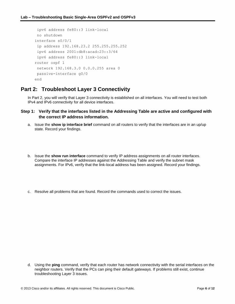
Lab – Troubleshooting Basic Single-Area OSPFv2 and OSPFv3
© 2013 Cisco and/or its affiliates. All rights reserved. This document is Cisco Public. Page 6 of 12
ipv6 address fe80::3 link-local
no shutdown
interface s0/0/1
ip address 192.168.23.2 255.255.255.252
ipv6 address 2001:db8:acad:23::3/64
ipv6 address fe80::3 link-local
router ospf 1
network 192.168.3.0 0.0.0.255 area 0
passive-interface g0/0
end
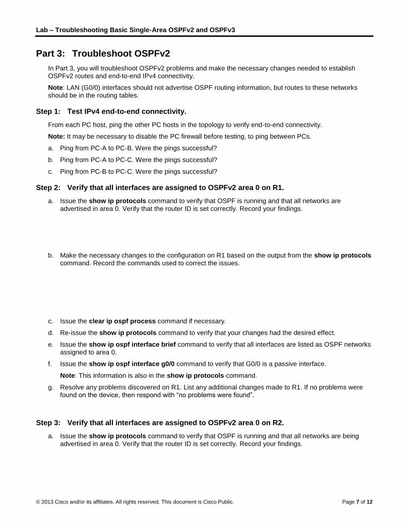
Part 2: Troubleshoot Layer 3 Connectivity
In Part 2, you will verify that Layer 3 connectivity is established on all interfaces. You will need to test both IPv4 and IPv6 connectivity for all device interfaces.
Step 1: Verify that the interfaces listed in the Addressing Table are active and configured with
the correct IP address information.
a. Issue the show ip interface brief command on all routers to verify that the interfaces are in an up/up state. Record your findings.
b. Issue the show run interface command to verify IP address assignments on all router interfaces. Compare the interface IP addresses against the Addressing Table and verify the subnet mask assignments. For IPv6, verify that the link-local address has been assigned. Record your findings.
c. Resolve all problems that are found. Record the commands used to correct the issues.
d. Using the ping command, verify that each router has network connectivity with the serial interfaces on the neighbor routers. Verify that the PCs can ping their default gateways. If problems still exist, continue troubleshooting Layer 3 issues.
Lab – Troubleshooting Basic Single-Area OSPFv2 and OSPFv3
© 2013 Cisco and/or its affiliates. All rights reserved. This document is Cisco Public. Page 7 of 12
Part 3: Troubleshoot OSPFv2
In Part 3, you will troubleshoot OSPFv2 problems and make the necessary changes needed to establish OSPFv2 routes and end-to-end IPv4 connectivity.
Note: LAN (G0/0) interfaces should not advertise OSPF routing information, but routes to these networks should be in the routing tables.
Step 1: Test IPv4 end-to-end connectivity.
From each PC host, ping the other PC hosts in the topology to verify end-to-end connectivity.
Note: It may be necessary to disable the PC firewall before testing, to ping between PCs.
a. Ping from PC-A to PC-B. Were the pings successful?
b. Ping from PC-A to PC-C. Were the pings successful?
c. Ping from PC-B to PC-C. Were the pings successful?
Step 2: Verify that all interfaces are assigned to OSPFv2 area 0 on R1.
a. Issue the show ip protocols command to verify that OSPF is running and that all networks are advertised in area 0. Verify that the router ID is set correctly. Record your findings.
b. Make the necessary changes to the configuration on R1 based on the output from the show ip protocols command. Record the commands used to correct the issues.
c. Issue the clear ip ospf process command if necessary.
d. Re-issue the show ip protocols command to verify that your changes had the desired effect.
e. Issue the show ip ospf interface brief command to verify that all interfaces are listed as OSPF networks assigned to area 0.
f. Issue the show ip ospf interface g0/0 command to verify that G0/0 is a passive interface.
Note: This information is also in the show ip protocols command.
g. Resolve any problems discovered on R1. List any additional changes made to R1. If no problems were found on the device, then respond with “no problems were found”.
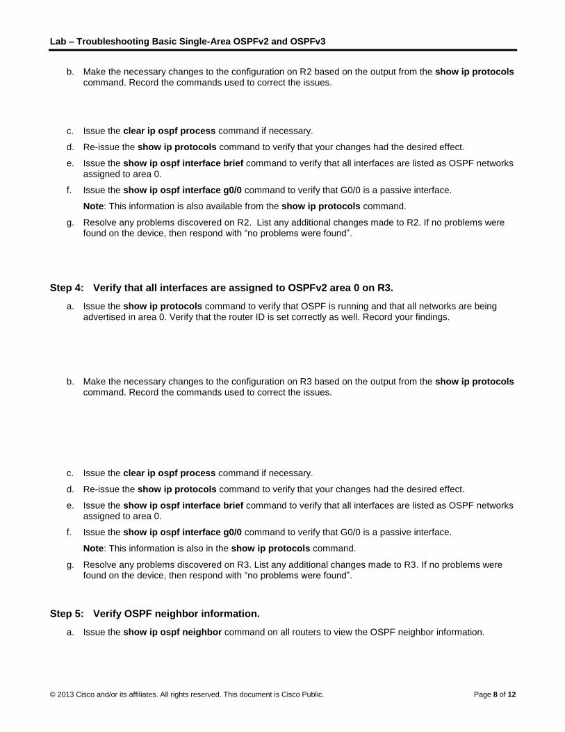
Step 3: Verify that all interfaces are assigned to OSPFv2 area 0 on R2.
a. Issue the show ip protocols command to verify that OSPF is running and that all networks are being advertised in area 0. Verify that the router ID is set correctly. Record your findings.
Lab – Troubleshooting Basic Single-Area OSPFv2 and OSPFv3
© 2013 Cisco and/or its affiliates. All rights reserved. This document is Cisco Public. Page 8 of 12
b. Make the necessary changes to the configuration on R2 based on the output from the show ip protocols command. Record the commands used to correct the issues.
c. Issue the clear ip ospf process command if necessary.
d. Re-issue the show ip protocols command to verify that your changes had the desired effect.
e. Issue the show ip ospf interface brief command to verify that all interfaces are listed as OSPF networks assigned to area 0.
f. Issue the show ip ospf interface g0/0 command to verify that G0/0 is a passive interface.
Note: This information is also available from the show ip protocols command.
g. Resolve any problems discovered on R2. List any additional changes made to R2. If no problems were found on the device, then respond with “no problems were found”.
Step 4: Verify that all interfaces are assigned to OSPFv2 area 0 on R3.
a. Issue the show ip protocols command to verify that OSPF is running and that all networks are being advertised in area 0. Verify that the router ID is set correctly as well. Record your findings.
b. Make the necessary changes to the configuration on R3 based on the output from the show ip protocols command. Record the commands used to correct the issues.
c. Issue the clear ip ospf process command if necessary.
d. Re-issue the show ip protocols command to verify that your changes had the desired effect.
e. Issue the show ip ospf interface brief command to verify that all interfaces are listed as OSPF networks assigned to area 0.
f. Issue the show ip ospf interface g0/0 command to verify that G0/0 is a passive interface.
Note: This information is also in the show ip protocols command.
g. Resolve any problems discovered on R3. List any additional changes made to R3. If no problems were found on the device, then respond with “no problems were found”.
Step 5: Verify OSPF neighbor information.
a. Issue the show ip ospf neighbor command on all routers to view the OSPF neighbor information.
Lab – Troubleshooting Basic Single-Area OSPFv2 and OSPFv3
© 2013 Cisco and/or its affiliates. All rights reserved. This document is Cisco Public. Page 9 of 12
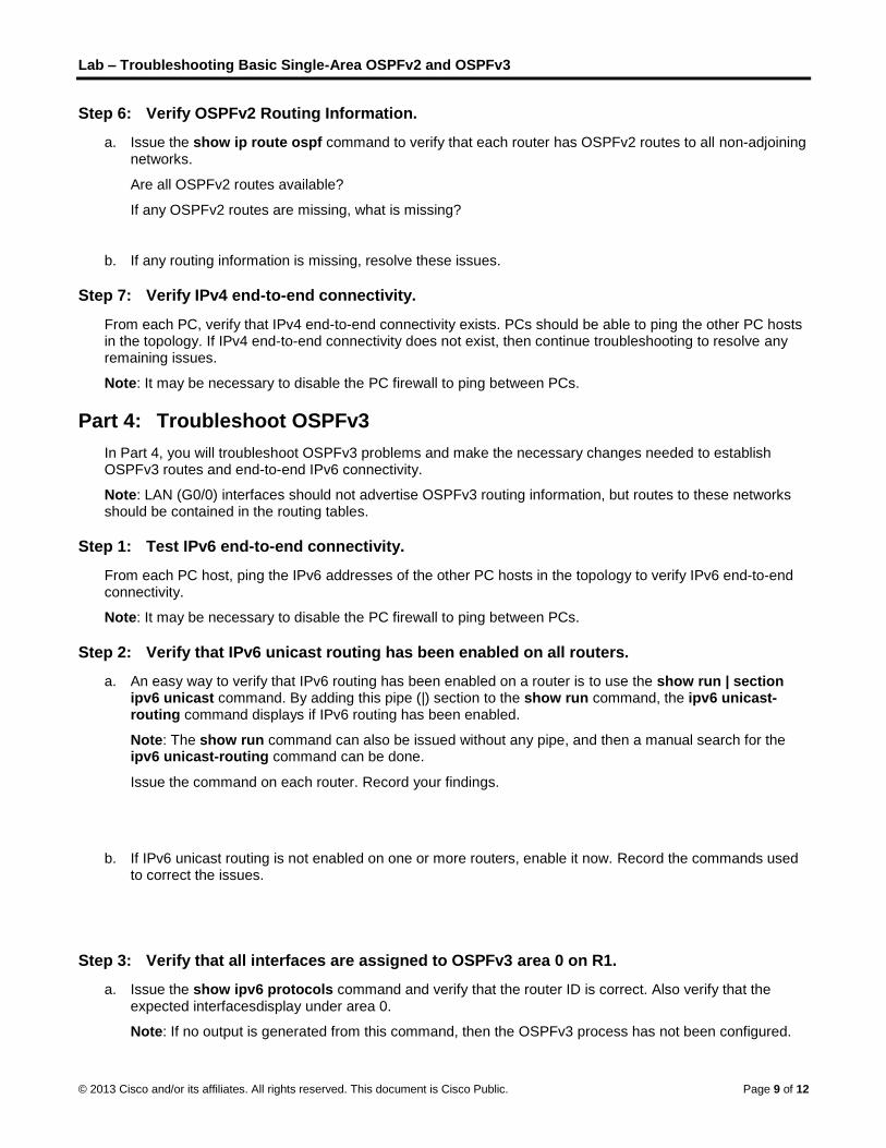
Step 6: Verify OSPFv2 Routing Information.
a. Issue the show ip route ospf command to verify that each router has OSPFv2 routes to all non-adjoining networks.
Are all OSPFv2 routes available?
If any OSPFv2 routes are missing, what is missing?
b. If any routing information is missing, resolve these issues.
Step 7: Verify IPv4 end-to-end connectivity.
From each PC, verify that IPv4 end-to-end connectivity exists. PCs should be able to ping the other PC hosts in the topology. If IPv4 end-to-end connectivity does not exist, then continue troubleshooting to resolve any remaining issues.
Note: It may be necessary to disable the PC firewall to ping between PCs.
Part 4: Troubleshoot OSPFv3
In Part 4, you will troubleshoot OSPFv3 problems and make the necessary changes needed to establish OSPFv3 routes and end-to-end IPv6 connectivity.
Note: LAN (G0/0) interfaces should not advertise OSPFv3 routing information, but routes to these networks should be contained in the routing tables.
Step 1: Test IPv6 end-to-end connectivity.
From each PC host, ping the IPv6 addresses of the other PC hosts in the topology to verify IPv6 end-to-end connectivity.
Note: It may be necessary to disable the PC firewall to ping between PCs.
Step 2: Verify that IPv6 unicast routing has been enabled on all routers.
a. An easy way to verify that IPv6 routing has been enabled on a router is to use the show run | section ipv6 unicast command. By adding this pipe (|) section to the show run command, the ipv6 unicast-routing command displays if IPv6 routing has been enabled.
Note: The show run command can also be issued without any pipe, and then a manual search for the ipv6 unicast-routing command can be done.
Issue the command on each router. Record your findings.
b. If IPv6 unicast routing is not enabled on one or more routers, enable it now. Record the commands used to correct the issues.
Step 3: Verify that all interfaces are assigned to OSPFv3 area 0 on R1.
a. Issue the show ipv6 protocols command and verify that the router ID is correct. Also verify that the expected interfacesdisplay under area 0.
Note: If no output is generated from this command, then the OSPFv3 process has not been configured.
Lab – Troubleshooting Basic Single-Area OSPFv2 and OSPFv3
© 2013 Cisco and/or its affiliates. All rights reserved. This document is Cisco Public. Page 10 of 12
Record your findings.
b. Make the necessary configuration changes to R1. Record the commands used to correct the issues.
c. Issue the clear ipv6 ospf process command if necessary.
d. Re-issue the show ipv6 protocols command to verify that your changes had the desired effect.
e. Issue the show ipv6 ospf interface brief command to verify that all interfaces are listed as OSPF networks assigned to area 0.
f. Issue the show ipv6 ospf interface g0/0 command to verify that this interface is set not to advertise OSPFv3 routes.
g. Resolve any problems discovered on R1. List any additional changes made to R1. If no problems were found on the device, then respond with “no problems were found”.
Step 4: Verify that all interfaces are assigned to OSPFv3 area 0 on R2.
a. Issue the show ipv6 protocols command and verify the router ID is correct. Also verify that the expected interfaces display under area 0.
Note: If no output is generated from this command, then the OSPFv3 process has not been configured.
Record your findings.
b. Make the necessary configuration changes to R2. Record the commands used to correct the issues.
c. Issue the clear ipv6 ospf process command if necessary.
d. Re-issue the show ipv6 protocols command to verify that your changes had the desired effect.
e. Issue the show ipv6 ospf interface brief command to verify that all interfaces are listed as OSPF networks assigned to area 0.
f. Issue the show ipv6 ospf interface g0/0 command to verify that this interface is not set to advertise OSPFv3 routes.
g. List any additional changes made to R2. If no problems were found on the device, then respond with “no problems were found”.
Lab – Troubleshooting Basic Single-Area OSPFv2 and OSPFv3
© 2013 Cisco and/or its affiliates. All rights reserved. This document is Cisco Public. Page 11 of 12
Step 5: Verify that all interfaces are assigned to OSPFv3 area 0 on R3.
a. Issue the show ipv6 protocols command and verify that the router ID is correct. Also verify that the expected interfaces display under area 0.
Note: If no output is generated from this command, then the OSPFv3 process has not been configured.
Record your findings.
b. Make the necessary configuration changes to R3. Record the commands used to correct the issues.
c. Issue the clear ipv6 ospf process command if necessary.
d. Re-issue the show ipv6 protocols command to verify that your changes had the desired effect.
e. Issue the show ipv6 ospf interface brief command to verify that all interfaces are listed as OSPF networks assigned to area 0.
f. Issue the show ipv6 ospf interface g0/0 command to verify that this interface is set not to advertise OSPFv3 routes.
g. Resolve any problems discovered on R3. List any additional changes made to R3. If no problems were found on the device, then respond with “no problems were found”.
Step 6: Verify that all routers have correct neighbor adjacency information.
a. Issue the show ipv6 ospf neighbor command to verify that adjacencies have formed between neighboring routers.
b. Resolve any OSPFv3 adjacency issues that still exist.
Step 7: Verify OSPFv3 routing information.
a. Issue the show ipv6 route ospf command, and verify that OSPFv3 routes exist to all non-adjoining networks.
Are all OSPFv3 routes available?
If any OSPFv3 routes are missing, what is missing?
b. Resolve any routing issues that still exist.
Step 8: Verify IPv6 end-to-end connectivity.
From each PC, verify that IPv6 end-to-end connectivity exists. PCs should be able to ping each interface on the network. If IPv6 end-to-end connectivity does not exist, then continue troubleshooting to resolve remaining issues.
Note: It may be necessary to disable the PC firewall to ping between PCs.
Lab – Troubleshooting Basic Single-Area OSPFv2 and OSPFv3
© 2013 Cisco and/or its affiliates. All rights reserved. This document is Cisco Public. Page 12 of 12
Reflection
Why would you troubleshoot OSPFv2 and OSPFv3 separately?
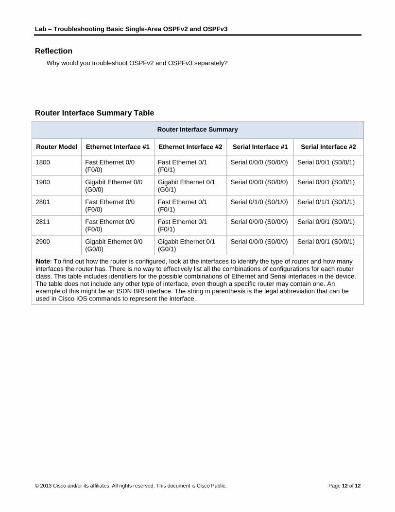
Router Interface Summary Table
Router Interface Summary
Router Model Ethernet Interface #1 Ethernet Interface #2 Serial Interface #1 Serial Interface #2
1800 Fast Ethernet 0/0 (F0/0)
Fast Ethernet 0/1 (F0/1)
Serial 0/0/0 (S0/0/0) Serial 0/0/1 (S0/0/1)
1900 Gigabit Ethernet 0/0 (G0/0)
Gigabit Ethernet 0/1 (G0/1)
Serial 0/0/0 (S0/0/0) Serial 0/0/1 (S0/0/1)
2801 Fast Ethernet 0/0 (F0/0)
Fast Ethernet 0/1 (F0/1)
Serial 0/1/0 (S0/1/0) Serial 0/1/1 (S0/1/1)
2811 Fast Ethernet 0/0 (F0/0)
Fast Ethernet 0/1 (F0/1)
Serial 0/0/0 (S0/0/0) Serial 0/0/1 (S0/0/1)
2900 Gigabit Ethernet 0/0 (G0/0)
Gigabit Ethernet 0/1 (G0/1)
Serial 0/0/0 (S0/0/0) Serial 0/0/1 (S0/0/1)
Note: To find out how the router is configured, look at the interfaces to identify the type of router and how many interfaces the router has. There is no way to effectively list all the combinations of configurations for each router class. This table includes identifiers for the possible combinations of Ethernet and Serial interfaces in the device. The table does not include any other type of interface, even though a specific router may contain one. An example of this might be an ISDN BRI interface. The string in parenthesis is the legal abbreviation that can be used in Cisco IOS commands to represent the interface.