ospf deployment in modern networksd2zmdbbm9feqrf.cloudfront.net/2014/usa/pdf/brkrst-2337.pdf · •...
TRANSCRIPT


OSPF Deployment in Modern Networks
BRKRST-2337
Faraz Shamim

© 2014 Cisco and/or its affiliates. All rights reserved. BRKRST-2337 Cisco Public
OSPF Deployment in Modern Networks
– IPv6 Enhancements • Challenges of OSPFv3 IPv6 deployments • Multi-Address Family support for OSPFv3
– Core • Scalability
– Data Center • Resiliency and fast convergence techniques
– Access • Hub and Spoke / Border Connections
– WAN • Design consideration when OSPF is used as a MPLS
PE CE protocol

© 2014 Cisco and/or its affiliates. All rights reserved. BRKRST-2337 Cisco Public
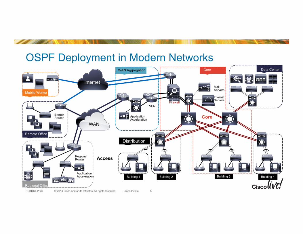
OSPF Deployment in Modern Networks
• Typical enterprise network is built upon multiple levels of switches deployed in three general layers: access (to include WAN Aggregation), distribution and core
• Core: – Provides high speed connectivity between aggregation layers - gets traffic from one
area of the network to another.
• Distribution: – Provides aggregation of traffic flows from multiple Access layers to the Core. Traffic
filtering and packet policies are typically implemented here. The distribution layer should be the blocking point for Queries (more about this later)
• Access / WAN Aggregation: – Provide connectivity to user attachment points for servers, end stations, storage
devices, and other IP devices. – Provides connectivity to the internet and/or remote sites/offices.
4
© 2014 Cisco and/or its affiliates. All rights reserved. BRKRST-2337 Cisco Public
OSPF Deployment in Modern Networks
Building 1
Distribution
Access
WAN Aggregation
Application Acceleration
VPN
Building 3
Core
Firewall
Internet Servers
Mail Servers
Core
Building 4 Building 2
Data Center
WAN
Internet
Mobile Worker
Remote Office
Branch Router
Regional Office
Regional Router
Application Acceleration
5

© 2014 Cisco and/or its affiliates. All rights reserved. BRKRST-2337 Cisco Public
OSPFv3 Address Family Support for IPv4/IPv6
Enables IPv4 and IPv6 address families to be supported on a single network infrastructure.
• OSPFv3 & OSPFv2 can be run concurrently – Cisco supports both – Each address family has a separate SPF
(Ships in the Night)
• Design and deployment techniques are same as with OSPFv2 – Not compatible with OSPFv2 – Training is required to understand the similarities and
differences – Troubleshooting could be a challenge (initially) – LSA format changes, and introduction of two new LSA’s
ipv6 unicast-routing!!!interface TenGig0/0/0/1! ip address 192.168.1.1 255.255.255.0 ! ipv6 enable! ospfv3 1 area 0 ipv6! ospfv3 1 area 1 ipv4!!!router ospfv3 1! address-family ipv4 unicast! router-id 10.1.1.1! exit-address-family!!! address-family ipv6 unicast! router-id 10.1.1.1! exit-address-family!
6

© 2014 Cisco and/or its affiliates. All rights reserved. BRKRST-2337 Cisco Public
OSPFv3 Address Family Support
• Multi-topology(multi-address family) RFC-5838 – Can be applied in green fields – Most common approach will be multi instance RFC-5340 – Reduced complexity
• OSPFv3 support for IPv6 – Link local routing brings a concept of scalable routing – Uses IPv6 transport and uses link-local addresses as source
address.
• Design deployment techniques are still the same as with OSPFv2 – Training is required to understand the similarities and differences – Troubleshooting could be a challenge (initially) – LSA format changes, and introduction of two new LSA’s
IPv4 IPv6
IPv6 IPv4
IPv4 IPv6 IPv4/IPv6
7

© 2014 Cisco and/or its affiliates. All rights reserved. BRKRST-2337 Cisco Public
OSPFv3 vs. OSPFv2
• Runs directly over IPv6 (port 89) • Uses the same basic packet types • Neighbor discovery and adjacency formation mechanisms are identical (All OSPF
Routers FF02::5, All OSPF DRs FF02::6) • LSA flooding and aging mechanisms are identical • Same interface types (P2P, P2MP, Broadcast, NBMA, Virtual) • Independent process from OSPFv2
Similar Concepts
• Removal of Addressing Semantics - Because IP addressing is now separated from the calculation of the SPF tree
• Per Link Processing • Addition of flooding scope • Two new LSAs • Handling of unknown LSA types • Virtual Link Changes • Authentication changes
Differences
8

© 2014 Cisco and/or its affiliates. All rights reserved. BRKRST-2337 Cisco Public
OSPFv3 — Address-Family Support • The OSPFv3 Address Families feature enables IPv4
nodes on separate subnets to peer using IPv6 link-local addresses.
• OSPFv3 improves upon OSPFv2 scalability for IPv4 by leveraging the Intra-Area-Prefix LSA to advertise connected prefixes.
• Because IP addressing is now separated from the calculation of the SPF tree, OSPFv3 interior routers do not have to flood the entire area when a topology change occurs
• This is especially advantageous for large IPv4-based single-area topologies with lots of access devices.
9
IPv6
IPv4
IPv4

© 2014 Cisco and/or its affiliates. All rights reserved. BRKRST-2337 Cisco Public
OSPFv3 — VRF Enhancements • OSPFv3 as a PE-CE routing protocol in MPLS VPN
• OSPFv3 VRF-lite support (OSPFv3 in VRFs without MPLS backbone)
• OSPFv3 sham-links are intra-area links configured between the PE routers
• All features supported for IPv6 and IPv4 address-families
vrf green
vrf red
vrf green
vrf lite multi-vrf CE
sham-links MPLS BGP
10

© 2014 Cisco and/or its affiliates. All rights reserved. BRKRST-2337 Cisco Public
OSPFv3 — Not So Stubby Areas (NSSA)
• Previous implementation was accordingly to RFC 1587
• Enhancements to the import of OSPF's summary routes. – Import of OSPF's summary routes into an NSSA as
Type-3 summary- LSAs is now optional.
• Changes to Type-7 LSA; – Changes to translating Type-7 LSAs into Type-5 LSAs – Changes to flushing translated Type-7 LSAs – Changes to the Type-7 AS external routing calculation.
• P-bit (propagate bit) – The P-bit default has been defined as clear
Updated OSPFv3 to latest IETF Standard RFC-3101
11

© 2014 Cisco and/or its affiliates. All rights reserved. BRKRST-2337 Cisco Public
OSPFv3 — SNMP MIB Support
• Polled objects and traps/notifications
• Standards-based SNMP management of OSPFv3 protocol
12
SNMP Management Station
OSPFv3 router
Additional CCO information http://www.cisco.com/public/sw-center/netmgmt/cmtk/mibs.shtml http://www.cisco.com/go/mibs ftp://ftp.cisco.com/pub/mibs/oid/
12

© 2014 Cisco and/or its affiliates. All rights reserved. BRKRST-2337 Cisco Public
OSPFv3 — Generalized TTL Security Mechanism
• Protects OSPFv3 virtual interfaces (virtual links and sham links) from attacks by remote hackers
• Allows user to configure maximum hop count which OSPFv3 protocol packets may travel over these virtual interfaces
• OSPFv3 protocol packets which traveled more hops than allowed are dropped early in processing
13
2001::1/96 2001::2/96
OSPFv3 AF IPv6
13

© 2014 Cisco and/or its affiliates. All rights reserved. BRKRST-2337 Cisco Public
OSPFv3 — Hiding Transit-Only Networks
• Support for IETF Standard RFC 6860
• Infrastructure link may have IPv4 and IPv6 addresses which, by default, are advertised by OSPFv3 using intra-area-prefix-LSA.
• Resource saving, and convergence improvements
• Remote attack vulnerability reduction
Selectively turn on/off infrastructure prefix advertisements
14
10.1.1.1/24 10.1.1.2/24
2001::1/96 2001::2/96
OSPFv3 AF IPv6
OSPFv3 AF IPv4
router ospfv3 1! prefix-suppression!! address-family ipv4 unicast! prefix-suppression ! address-family ipv6 unicast! prefix-suppression end!
14

© 2014 Cisco and/or its affiliates. All rights reserved. BRKRST-2337 Cisco Public
Bring adjacency down
OSPFv3 — Graceful Shutdown
• Configuration command to place OSPFv3 Address-Family in a ‘down’ state – Takes OSPFv3 router out of the service – Most of events ignored during shutdown – Only configuration events are processed – “no shutdown” restores normal operation
• Uses LSA flushing to notify other routers to route around, empty hello sent to speed up neighbor DOWN event on the peers.
R(config)#router ospfv3 1!
R(config-router)# shutdown!
RTR LSA
MAXAGE
Bring adjacency down
15

© 2014 Cisco and/or its affiliates. All rights reserved. BRKRST-2337 Cisco Public
OSPFv3 — Graceful Shutdown
• OSPFv3 Max-metric Router LSA – Diverts traffic around the router if alternate paths are available in the
network
• OSPFv3 External Path Preference Option (RFC 5340) – Prevents routing loop when calculating best path
for external routes – Intra-area paths using non-backbone areas are
always the most preferred – The other paths, intra-area backbone paths and
inter- area paths, are of equal preference.
Set max-metric (do not use this router)
16

© 2014 Cisco and/or its affiliates. All rights reserved. BRKRST-2337 Cisco Public
OSPFv3 Area filter
• Area filter controls which intra and inter area routes are propagated by ABR into an area using inter area LSAs.
• Resource saving on intra area routers without need to configure whole area stub or NSSA.
15.3(1)S/XE3.8
ABR ABR Area 0
Area 1
LSA 1
Prefix 1
Prefix 2
Prefix 3
LSA 4
Prefix 4
Prefix allowed by area filter Prefix not allowed by area filter
router ospfv3 1!
address-family ipv4 unicast area 2!
filter-list prefix test_ipv4 in!
exit-address-family !!
address-family ipv6 unicast area 2!
filter-list prefix test_ipv6 in !
exit-address-family !
! !
ip prefix-list test_ipv4 seq 5 permit 2.2.2.2/32 !
ipv6 prefix-list test_ipv6 seq 5 deny 2011::1/128 !
17

© 2014 Cisco and/or its affiliates. All rights reserved. BRKRST-2337 Cisco Public
Core
Building 1 Building 2 Building 4
Data Center
WAN
Access
Mobile Worker
Remote Office
Branch Router
Regional Office
Regional Router
WAN Aggregation
Application Acceleration
Application Acceleration
VPN
Core
Firewall
Internet Servers
Mail Servers
Core
Internet
Building 3
Distribution
18

© 2014 Cisco and/or its affiliates. All rights reserved. BRKRST-2337 Cisco Public
Link State—Areas, Router Types, DB
Area 0
Area 11
Area 12
Backbone
Internal Internal
Internal
ABR
ASBR
ABR
ABR
ABR
• A router has a separate LS database for each area to which it belongs
• All routers belonging to the same area should have identical databases
• SPF calculation is performed independently for each area
• LSA flooding is bounded by area
Area 10
RIP/RIPv2 World
• Areas: the tool to make OSPF Scale! • OSPF uses a 2 level hierarchical model • One SPF per area, flooding
done per area • Regular, Stub, Totally Stubby and NSSA Area
Types
19

© 2014 Cisco and/or its affiliates. All rights reserved. BRKRST-2337 Cisco Public
Link State—Location of Different LSAs
Area 0
Area 11
Area 12
Backbone
Internal Internal
Internal
ABR
ASBR
ABR
ABR
ABR
Area 10
RIP/RIPv2 World
Type3
Type4/5
Network changes generates link-state advertisements (LSA) • Router LSA (Type 1) • Network LSA (Type 2) • Summary LSA (type 3 and type 4) • External LSA (type 5)
• All routers exchange LSAs to build and maintain a consistent database
• The protocol remains relatively quiet during steady-state conditions
• Periodic refresh of LSAs every 30 minutes • Otherwise, updates only sent when there are
changes
20

© 2014 Cisco and/or its affiliates. All rights reserved. BRKRST-2337 Cisco Public
Link State—Location of Different LSAs
Area 0
Area 11
Area 12
Backbone
Internal Internal
Internal
ABR
ASBR
ABR
ABR
ABR
Area 10
RIP/RIPv2 World
• LSA flooded throughout the area in response to any topology change
• SPF runs in every router on the receipt of any LSA indicating a topology change
• OSPF by design has a number of throttling mechanisms to prevent the network from thrashing during periods of instability
• Full SPF - Triggered by the change in Router or Network LSA
- All LSA types are processed
• Partial SPF - Triggered by the change in Type-3/4/5/7 LSA
- Part of the LSAs are processed (see slide notes)
21

© 2014 Cisco and/or its affiliates. All rights reserved. BRKRST-2337 Cisco Public
Area Size: How Many Router in an Area?
• Number of adjacent neighbors is more a factor!
• More important from the standpoint of the amount of information flooded in area
• Keep router LSAs under MTU size – Implies lots of interfaces (and possibly lots of neighbors) – Exceeding results in IP fragmentation which should be avoided
Area 1
22

© 2014 Cisco and/or its affiliates. All rights reserved. BRKRST-2337 Cisco Public
Area Size: How Many ABRs per Area?
• More ABRs will create more Type 3 LSA replication within the backbone and in other areas
• In a large scale routing this can cause scalability issues
• 5 prefixes in area 0 and 5 in area 1 could generate 30 summary LSAs all together with just 3 ABRs.
• Increase in areas or ABRs could worsen the situation ABR1
Backbone
Area 1
ABR2 ABRn
23

© 2014 Cisco and/or its affiliates. All rights reserved. BRKRST-2337 Cisco Public
Area Size: How Many Areas per ABR?
• More areas per ABR will put a significant burden on the ABR
• More Type 3 LSA will be generated by the ABR
• 5 prefixes in area 0 and 5 in each areas could generate 60 summary LSAs all together.
• Increase in areas or ABRs could worsen the situation Area 1
Backbone
Area 2
24

© 2014 Cisco and/or its affiliates. All rights reserved. BRKRST-2337 Cisco Public
Intra-Area Routing Scalability
• Physical link flaps can cause instability in OSPF
• Avoid having Physical links in OSPF through prefix-suppression feature
• BGP can be introduce to carry Physical links for monitor purpose
• Do redistributed connected in BGP to carry the physical links
• This will make intra area routing very scalable
Access
Wan links
NMS BGP
Regional Core
RR
WAN
25

© 2014 Cisco and/or its affiliates. All rights reserved. BRKRST-2337 Cisco Public
Intra-Area Routing Scalability
• Physical links outside the area should be filtered via Type 3 LSA filtering feature.
• Every area should carry only loopback addresses for all routers
• Only NMS station will keep track of those physical links
• These links can be advertised in BGP via redistribute connected
• This will bring scalability in the backbone
Access
Regional Core
ABR
Area 1
NMS WAN
Distribution
Area 0
26

© 2014 Cisco and/or its affiliates. All rights reserved. BRKRST-2337 Cisco Public
Area 10 11.1/16
Area 0
10
50 50
20 20
11.1.1/24
11.1.2/24 11.1.130/24
11.1.129/24
10
Summarization Technique
• Configure on Both ABRs – Area-Range 11.1.0/17 – Area-Range 11.1.128/17
• Cost to Range 1: – Via ABR1: 30 – Via ABR2: 80
• Cost to Range 2: – Via ABR1: 80 – Via ABR2: 30
27
ABR1 ABR2
R3 R4
R5 R6

© 2014 Cisco and/or its affiliates. All rights reserved. BRKRST-2337 Cisco Public
IGP 1
IGP 2 IGP 3
IGP 4 BGP Core USA
France Germany
Japan
IGP 6 IGP 5
Brazil Canada
Redistribution Best Practices
• Can have multiple ‘islands’ of IGPs
• Islands tied together by a BGP core
• One island’s instability will not impact other Islands
• May be a requirement for redistribution
• This design increases network stability & scalability BUT slows down the network convergence
28

© 2014 Cisco and/or its affiliates. All rights reserved. BRKRST-2337 Cisco Public
iBGP Core / Area 0 POP POP
POP
Redistribution Best Practices
• Should be careful with the router that is receiving full internet routes
• Redistribution of BGP into OSPF can melt the network down
• Areas should be defined as stub when possible to prevent accidental redistribution of eBGP into OSPF
• iBGP routes can not be redistributed into IGP by default
eBGP eBGP
eBGP eBGP
ABR
OSPF Stub Area
OSPF Stub Area
OSPF Stub Area
OSPF Stub Area
POP
29

© 2014 Cisco and/or its affiliates. All rights reserved. BRKRST-2337 Cisco Public
Dealing with Redistribution
• The number of redistribution boundaries should be kept to a minimum – You have better things to do in life besides building the access lists!
• When redistributing try to place the DR as close to the ASBR as possible to minimize flooding
• If possible make an area NSSA – To reduce type 4 in the network specially when there are too many ASBRs in an area
• NSSA will also give the flexibility to filter type 5 at the ABR level
• Redistribute only what is absolutely necessary – Don’t redistribute full Internet routes into OSPF! – Default route into BGP core; let the core worry about final destination
30

© 2014 Cisco and/or its affiliates. All rights reserved. BRKRST-2337 Cisco Public
Dealing with Redistribution
• Be aware of metric requirements going from one protocol to another – RIP metric is a value from 1–16 – OSPF Metric is from 1–65535 – EIGRP Metric is 1-4,294,967,296
• Include a redistribution default metric command as a protection
router ospf 1!network 130.93.0.0 0.0.255.255 area 0.0.0.0 !redistribute rip metric 1 subnets
31

© 2014 Cisco and/or its affiliates. All rights reserved. BRKRST-2337 Cisco Public
Data Center
Building 1 Building 2 Building 3 Building 4
Core WAN
Internet
Access
Mobile Worker
Remote Office
Branch Router
Regional Office
Regional Router
WAN Aggregation
Application Acceleration
Application Acceleration
VPN Firewall
Internet Servers
Mail Servers
Core Data Center
Distribution
32

© 2014 Cisco and/or its affiliates. All rights reserved. BRKRST-2337 Cisco Public
Data Center
• The Core can (and may) be used as the data center core.
• Video, voice or other rich media traffic is placing ever-increasing demands on the physical layer
• Consider the following items when determining the right core solution: – 10GigE density—Will there be enough 10GigE ports on the core switch pair to support
both the campus distribution as well as the data center aggregation modules? – Administrative domains and policies—Separate cores help to isolate campus distribution
layers from data center aggregation layers in terms of troubleshooting, administration, and policies (QoS, ACLs, troubleshooting, and maintenance).
– Future anticipation—The impact that can result from implementing a separate data center core layer at a later date might make it worthwhile to install it at the beginning.
• A robust infrastructure is needed to handle these demands
Data Centers are at the core of your business activity
33

© 2014 Cisco and/or its affiliates. All rights reserved. BRKRST-2337 Cisco Public
Fast(er) Network Convergence
• Network convergence is the time needed for traffic to be rerouted to the alternative or more optimal path after the network event
• Network convergence requires all affected routers to process the event and update the appropriate data structures used for forwarding
• Network convergence is the time required to: – Detect the event – Propagate the event – Process the event – Update the routing table/FIB
34

© 2014 Cisco and/or its affiliates. All rights reserved. BRKRST-2337 Cisco Public
Network Convergence
Techniques/Tools for Fast Convergence • Carrier Delays
• Hello/dead timers
• Bi-Directional Forwarding Detection (BFD)
• LSA packet pacing
• Interface event dampening
• Exponential throttle timers for LSA and SPF
• MinLSArrival Interval
• Incremental SPF
Techniques/Tools for Resiliency • Stub router (e.g., max-metric)
• Graceful Restart/NSF
Detect
Detect
Detect
Propagate
Propagate
Process
Process
Process
35

© 2014 Cisco and/or its affiliates. All rights reserved. BRKRST-2337 Cisco Public
Improving Convergence — Detection
• OSPF supports aggressive timers to decrease link failure detection – Timers can be tuned to a minimum of 1 second dead interval – Number of Hello packets per seconds specified as multiplier – 3 to 20 – Interface dampening is recommended with sub-second hello timers – OSPF point-to-point network type to avoid designated router (DR) negotiation.
•
• Additional information • There are reasons for not recommending this and also for us not offering such low values; for
example, depending on the number of interfaces, hello rates can become CPU intensive and lead to spikes in processing/memory requirements
OSPF Aggressive Timers (Fast Hellos)
interface GigabitEthernet1/1!
dampening ip ospf dead-interval minimal hello-multiplier 5 ip ospf network point-to-point!
36

© 2014 Cisco and/or its affiliates. All rights reserved. BRKRST-2337 Cisco Public
Improving Convergence — Detection
• Cisco IOS Bidirectional Forwarding Detection (BFD) is a fast Hello at Layer 2.5 – BFD exhibits lower overhead than aggressive hellos – BFD is a heartbeat at Layer 2.5, provides sub-second failure detection – BFD can provide reaction time close to 50 milliseconds
• OSPF use BFD facilities which send extremely fast keep-alives between routers – BFD and OSPF works together, with OSPF as the upper layer protocol – BFD relies on the OSPF to tell it about neighbors – Notifications occur quickly when changes occur in Layer 2 state
Bidirectional Forwarding Detection (BFD)
Additional CCO information http://www.ietf.org/internet-drafts/draft-ietf-bfd-generic-02.txt http://www.ietf.org/internet-drafts/draft-ietf-bfd-base-05.txt
37

© 2014 Cisco and/or its affiliates. All rights reserved. BRKRST-2337 Cisco Public
OSPF Loop Free Alternative Fast ReRoute (FRR)
• IP-FRR is a mechanism that reduces traffic disruption to 10s of milliseconds in event of link or node failure
ü Per-prefix LFA FRR enabled via route-maps ü Per-prefix LFA FRR enabled for all areas unless explicitly specified
ü LFA FRR automatically enabled on OSPF interfaces ü No audit trail of potential LFAs is stored
ü Repair paths are computed for all prefixes though not all prefixes may have repair paths
• But…. ü It runs at the process level
ü Does not guarantee time limit
ü Performance depends on tuning and platform implementation
Support for IP Fast Reroute (IP-FRR)
Primary Path Repair Path
Primary Next-Hop Protecting Node
A B
C
38

© 2014 Cisco and/or its affiliates. All rights reserved. BRKRST-2337 Cisco Public
LFA Repair Path Selection Tie-Breaker
Option Description Flag Default Value
Srlg Prefer repair path not sharing same shared risk link group SRLG 10
Primary-path Prefer repair path that is primary path of prefix with multiple equal-cost primary paths (different from primary path being protected)
PrimPath 20
Interface-disjoint Prefer repair path that uses different next hop interface from protected primary path IntfDj 30
Lowest metric Prefer repair path with lowest metric CostWon 40
Linecard-disjoint Prefer primary and repair path use different linecard LC Dj 50
Node-protecting Prefer node protecting over link protecting NodeProt 60
Broadcast-interface-disjoint Primary and repair path do not share common broadcast interface BcastDj 70
Load-sharing Use Cisco hashing algorithm Loadshare 256
39

© 2014 Cisco and/or its affiliates. All rights reserved. BRKRST-2337 Cisco Public
Enabling OSPF LFA FRR
• IOS implements per-prefix LFA FRR
• Per-prefix LFA FRR enabled for all areas unless explicitly specified
• LFA FRR automatically enabled on OSPF interfaces
• No audit trail of potential LFAs is stored
• Repair paths are computed for all prefixes though not all prefixes may have repair paths
router ospf 1! router-id 10.1.1.1! fast-reroute per-prefix enable prefix-priority low! network 10.0.0.0 255.255.255.255 area 0! …!
40

© 2014 Cisco and/or its affiliates. All rights reserved. BRKRST-2337 Cisco Public
Configuration router mode
• Basic Router Mode • Advanced Router Mode
• Interface Mode
router ospf 1! fast-reroute per-prefix enable prefix-priority low! !
r401(config)#router ospf 1 !r401(config-router)#fast-reroute ?! keep-all-paths Keep LFA FRR audit trail! per-prefix Per-prefix LFA FRR parameters!!r401(config-router)#fast-reroute per-prefix ?! enable Enable LFA Fast Reroute! tie-break LFA FRR repair path selection policy tiebreaks!!r401(config-router)#fast-reroute per-prefix enable ?! area Area to enable LFA FRR in! prefix-priority Priority of prefixes to be protected!
r401(config-if)#ip ospf fast-reroute per-prefix ?! candidate If interface can be protecting! protection If interface can be protected!
41

© 2014 Cisco and/or its affiliates. All rights reserved. BRKRST-2337 Cisco Public
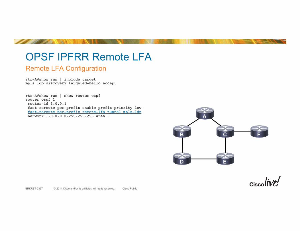
OPSF IPFRR Remote LFA • Next phase of IP Fast Reroute (IP FRR) feature originally released in XE 3.3
• One of problems intrinsic to directly connected LFA is less-than-full coverage, i.e. in some topologies not all prefixes are protected. Remote LFA addresses this limitation
Looping if directly connected LFA was used
Remote LFA tunnel solving this
A
B
D E
C F
42
© 2014 Cisco and/or its affiliates. All rights reserved. BRKRST-2337 Cisco Public
OPSF IPFRR Remote LFA
rtr-A#show run | include target!mpls ldp discovery targeted-hello accept!!!rtr-A#show run | show router ospf!router ospf 1! router-id 1.0.0.1! fast-reroute per-prefix enable prefix-priority low! fast-reroute per-prefix remote-lfa tunnel mpls-ldp! network 1.0.0.0 0.255.255.255 area 0!!
Remote LFA Configuration
A
B
D E
C F

© 2014 Cisco and/or its affiliates. All rights reserved. BRKRST-2337 Cisco Public
OPSF IPFRR Remote LFA
• The feature is supported only in global VPN routing and forwarding (VRF) OSPF instances.
• The only supported tunneling method is MPLS.
• You cannot configure a traffic engineering (TE) tunnel interface as a protected interface.
• Not all routes may have repair paths (depends on network topology)
• Devices selected as tunnel termination points must have a /32 address advertised in the area in which remote LFA is enabled.
• Devices selected as tunnel termination points must be configured to accept targeted LDP sessions using “mpls ldp discovery targeted-hello accept”!
Restrictions for OSPF IPv4 Remote LFA
44

© 2014 Cisco and/or its affiliates. All rights reserved. BRKRST-2337 Cisco Public
r801 1.0.0.1/32
r802 1.0.0.2/32
r803 1.0.0.3/32
r804 1.0.0.4/32
r805 1.0.0.5/32 5.0.0.1/8
S2/0
S3/0
OPSF IPFRR Remote LFA
r801#sh ip ospf fast-reroute remote-lfa tunnels !…!!Interface MPLS-Remote-Lfa1! Tunnel type: MPLS-LDP! Tailend router ID: 1.0.0.3! Termination IP address: 1.0.0.3! Outgoing interface: Serial2/0! First hop gateway: 1.0.0.2! Tunnel metric: 20! Protects:! 1.0.0.5 Serial3/0, total metric 40!!Interface MPLS-Remote-Lfa2! Tunnel type: MPLS-LDP! Tailend router ID: 1.0.0.4! Termination IP address: 1.0.0.4! Outgoing interface: Serial3/0! First hop gateway: 1.0.0.5! Tunnel metric: 20! Protects:! 1.0.0.2 Serial2/0, total metric 40!
Are tunnels created?
MPLS-Remote-Lfa1
MPLS-Remote-Lfa2
45

© 2014 Cisco and/or its affiliates. All rights reserved. BRKRST-2337 Cisco Public
OSPF Full Mesh
• 2 routers == 1 link
• 3 routers == 3 links
• 4 routers == 6 links
• 5 routers == 10 links
• 6 routers == 15 links
• N routers == ((N) (N-1)) / 2
• …
Full Mesh Topologies Are Complex
46

© 2014 Cisco and/or its affiliates. All rights reserved. BRKRST-2337 Cisco Public
OSPF Full Mesh
• Flooding routing information through a full mesh topology is the MAIN concern – Each router will receive at least one copy of new
information from each neighbor on the full mesh – Link down is n2 – Node down is n3 – Very large router LSA, node down could become n4
• There are several techniques you can use to reduce the amount of flooding in a full mesh – Mesh groups reduce the flooding in a full mesh network – Mesh groups are manually configured “designated routers”
New Information
47

© 2014 Cisco and/or its affiliates. All rights reserved. BRKRST-2337 Cisco Public
OSPF Full Mesh
• Pick a subset (>=2) of routers to flood into the mesh and block flooding on the remainder; leave flooding to these routers open
• This will reduce the number of times information is flooded over a full mesh topology
New Information
! Point-to-Point!interface serial 1/0! ip ospf database-filter all out! ....!!! Point-to-Multipoint!router ospf 1! neighbor 10.1.1.3 database-filter all out!
48

© 2014 Cisco and/or its affiliates. All rights reserved. BRKRST-2337 Cisco Public
Scalability with flood reduction RFC 4136
• Eliminates periodic refresh of unchanged LSAs
• Configured at interface level
• Very useful in fully meshed topologies
• Possible extension to force refresh at an increased interval, e.g. every four hours; currently not implemented – Changes could be missed if the sum of the changes results
in an identical checksum – Periodic refresh provides recovery from bugs and glitches
! All interfaces types interface ethernet 0/0 ip ospf flood-reduction ....!
49

© 2014 Cisco and/or its affiliates. All rights reserved. BRKRST-2337 Cisco Public
Distribution and Access
50
Core
Data Center
WAN
Internet
Mobile Worker
Remote Office
Branch Router
Regional Office
Regional Router
WAN Aggregation
Application Acceleration
Application Acceleration
VPN Firewall
Internet Servers
Mail Servers
Core
Building 4 Building 1 Building 2 Building 3
Distribution
Access

© 2014 Cisco and/or its affiliates. All rights reserved. BRKRST-2337 Cisco Public
OSPF Border Connections
• Dual homed connections in hub and spoke networks illustrate a design challenge in OSPF: connections parallel to an area border
• Assume the D to E link is in area 0
• If the D to F link fails, traffic from A to F will: – Route towards the summary advertised by D – Route via the more specific along the path G, E, F
Summarization
A B C
D E
F G
ABR-1 ABR-2
Backbone
Area 1
51

© 2014 Cisco and/or its affiliates. All rights reserved. BRKRST-2337 Cisco Public
OSPF Border Connections
• Let’s take a closer look at the problem
• Traffic prefers to stay within the area no matter what the actual link costs are – To reach A, we will take the higher cost link if the
border link is in the backbone – To reach B, we will take the higher cost link if the
border link is in the area – This is because we will always use an intra-area
path over an inter-area path
52
100
10 10
A
B 100
10.1.1.0/24, cost 10
100
10 10
A
B 100
10.1.1.0/24, cost 10 ABR-2
ABR-2 ABR-1
ABR-1
Backbone Area
Backbone Area
Area 1
Area 1

© 2014 Cisco and/or its affiliates. All rights reserved. BRKRST-2337 Cisco Public
OSPF Border Connections
• Then, either: – Decide which traffic you want to route optimally – Use either virtual circuits (sub-interfaces) or real
links to create one adjacency between the ABRs per routed area
• Configure the link in Area 1 with a virtual link in backbone (won’t work for more than one area)
53
100
10 10
A
B 100
10.1.1.0/24, cost 10
100
10 10
A
B 100
10.1.1.0/24, cost 10 ABR-2
ABR-2 ABR-1
ABR-1
Backbone Area
Backbone Area
Area 1
Area 1

© 2014 Cisco and/or its affiliates. All rights reserved. BRKRST-2337 Cisco Public
OSPF Border Connections
• Some tuning required for OSPF to work well in hub and spoke scenarios
• Enhancements are being made in IETF to make OSPF more robust on hub and spoke
• Other protocols like EIGRP, ODR, RIPv2 and BGP work better under hub and spoke model compare to OSPF
• Enterprise BGP is not complicated
• You do not need to play with a lot of attributes
54

© 2014 Cisco and/or its affiliates. All rights reserved. BRKRST-2337 Cisco Public
Hub and Spoke
• Summarization of areas will require specific routing information between the ABRs
• This is to avoid suboptimal routing
• The link between two hub routers should be equal to the number of areas
• As you grow the number of areas, you will grow the number of VLAN/PVCs — scalability issue
• Possible solution is to have a single link with adjacencies in multiple areas. (RFC 5185)
55
Trunk with One VLAN in Each Flooding Domain

© 2014 Cisco and/or its affiliates. All rights reserved. BRKRST-2337 Cisco Public
Multi Area Adjacency
• If Link 1 is in area 0, router C will choose an path through E, F, and D to 10.1.2.0/24 rather than Link1
• This is because OSPF always prefers intra-area routes over inter-area routes
• If Link 1 is put in area 1, router D will choose an path through B, A, and C to 10.1.3.0/24 with the same reason
Suboptimal path at Area Boundary
10.1
.3.0
/24
10.1
.2.0
/24
Area 0
Link 1
Area 1 Allows an interface to be in both areas:
rtr-C(config)# interface Ethernet 0/0!rtr-C(config-if)# ip address 10.0.12.1 255.255.255.0!rtr-C(config-if)# ip ospf 1 area 0!rtr-C(config-if)# ip ospf network point-to-point!rtr-C(config-if)# ip ospf multi-area 2!
A B
C
E
D
F
56

© 2014 Cisco and/or its affiliates. All rights reserved. BRKRST-2337 Cisco Public
A
D
C
OSPF Hub and Spoke
• Every router within a flooding domain receives the same information – Although B can only reach C through A, it still receives
all of C’s routing information
• Because of this, OSPF requires additional tuning for hub and spoke deployments
57
Reachability Only Through A
All Link State Information Is Flooded to B
B

© 2014 Cisco and/or its affiliates. All rights reserved. BRKRST-2337 Cisco Public
OSPF Hub and Spoke
• One of our primary goals is to control the amount of flooding towards the remotes
• You can reduce flooding by configuring the hub not to flood any information to the remotes at all – ip ospf database-filter all out – The remote routers must supply their own remote,
or the hub router must originate a default locally
• This isn’t a common configuration
58
Block Flooding Here
Static Routes Here
B
A
D
C
B

© 2014 Cisco and/or its affiliates. All rights reserved. BRKRST-2337 Cisco Public
OSPF Hub and Spoke
• The spoke areas should always be the “most stubby” you can get away with – If possible, make them totally stubby – If there is redistribution at the spokes, make the area
totally not-so-stubby
• The fewer spokes in each area the less flooding redundancy – However, less can be summarized in the backbone – Separate sub-interface is needed per area
• Totally stubby makes more sense in multiple area situation
59
Area 1
router ospf 100! area 1 stub no-summary! ....!
router ospf 100! redistribute rip metric 10! ....!
router ospf 100! area 1 nssa no-summary! ....!
ABR

© 2014 Cisco and/or its affiliates. All rights reserved. BRKRST-2337 Cisco Public
OSPF Hub and Spoke: Network Types
• OSPF could treat a multi-point link as a broadcast network or NBMA, but there are issues with flooding and forwarding – B and D don’t receive C’s packets, so they think A has
the highest IP address, and elect A as DR – C elects itself as DR – Flooding will fail miserably in this situation
• We can set the OSPF DR priorities so the hub router is always elected DR – Set the spokes to 0 so they don’t participate in DR election
60
“A Is DR” “C Is DR” “A Is DR”
“C Is DR”
B C D
interface s0/0! ip address 10.1.1. 255.255.255.0! ip ospf priority 200! ....!
interface s0! ip ospf priority 0! ....!
A

© 2014 Cisco and/or its affiliates. All rights reserved. BRKRST-2337 Cisco Public
OSPF Hub and Spoke: NBMA/Broadcast
• OSPF will still have forwarding issues since the OSPF broadcast and NBMA assume a full mesh
• There is bi-directional connectivity between A and B, C, and D
• B, C, and D cannot communicate amongst themselves and traffic will be black-holed
• One can get around this using DLCI routing at the Frame Relay layer
61
B C D
A

© 2014 Cisco and/or its affiliates. All rights reserved. BRKRST-2337 Cisco Public
OSPF Hub and Spoke: P2MP
• You can also configure the serial interface at the hub router as a point-to-multi-point type – All the remotes are in a single IP subnet – OSPF treats each remote as a separate
point-to-point link for flooding
• OSPF will advertise a host route to the IP address of each spoke router to provide connectivity
• Smaller DB Size compare to P2P
• Most natural OSPF solution
62
10.1.1.2/32 10.1.1.3/32 10.1.1.4/32 ....
interface s0/0! ip address 10.1.1.1 255.255.255.0! ip ospf network point-to-multipoint!
interface s0! ip address 10.1.1.x 255.255.255.0! ip ospf network point-to-multipoint!
B C D
A

© 2014 Cisco and/or its affiliates. All rights reserved. BRKRST-2337 Cisco Public
OSPF Hub and Spoke:
• OSPF can also use point-to-point sub-interfaces, treating each one as a separate point-to-point link
• Increase the DB size
• These use more address space and require more administration on the router – Use /31 addresses for these point to point links
P2P Sub-Interfaces
63
interface s0/0.1 point-to-point! ip address 10.1.1.0 255.255.255.254! ....!interface s0/0.2 point-to-point! ip address 10.1.1.2 255.255.255.254! ....!interface s0/0.3 point-to-point! ip address 10.1.1.4 255.255.255.254!
interface s0.1 point-to-point! ip address 10.1.1.x 255.255.255.254! ....!
B C D
A

© 2014 Cisco and/or its affiliates. All rights reserved. BRKRST-2337 Cisco Public
OSPF Hub and Spoke
64
Network Type Advantages Disadvantages
Single Interface at the Hub Treated as an OSPF Broadcast
or NBMA Network
Single IP Subnet
Fewer Host Routes in Routing Table
Manual Configuration of Each Spoke with the Correct OSPF
Priority
No Reachability Between Spokes or Labor-Intensive Layer 2 Configuration
Single Interface at the Hub Treated as an OSPF Point-to-
Multipoint Network
ip ospf Network-Type Point-to-Multipoint
Single IP Subnet
No Configuration per Spoke
Most Natural Solution
Smaller database
Additional Host Routes Inserted in the Routing Table
Individual Point-to-Point Interface at the Hub
for Each Spoke ip ospf Network-Type
Point-to-Point
Can Take Advantage of End-to-End Signaling for Down State
Lost IP Address Space
More Routes in the Routing Table
Larger database
Overhead of Sub-Interfaces

© 2014 Cisco and/or its affiliates. All rights reserved. BRKRST-2337 Cisco Public
OSPF Hub and Spoke
• The other consideration is determining how many spokes should fall within the area
• If the number of remotes are low, we can place the hub and its spokes within an area
• However, as the count rises, we want to make the hub an ABR, and split off the spokes in a single area
• If you’re going to summarize into and out of the remotes, the hub needs to be a border router
65
Small Number of Spokes
Large Number of Spokes
Summarize Here
ABR
Area 1
Backbone

© 2014 Cisco and/or its affiliates. All rights reserved. BRKRST-2337 Cisco Public
OSPF Hub and Spoke
• Low speed links and large numbers of spoke may require multiple flooding domains
• Balance the number of flooding domains on the hub against the number of spokes in each flooding domain
• The link speeds and the amount of information being passed through the network determines the right balance
66
Area 1
Backbone
Area 2

© 2014 Cisco and/or its affiliates. All rights reserved. BRKRST-2337 Cisco Public
OSPF Hub and Spoke
Selectively ignore Demand Circuit (DC) configurations from Spoke • A misconfiguration of DC on one spoke triggers Hub may cause (in case of p2mp interface
on the Hub) negotiation of demand circuits for other spokes (Spoke 1 and 2). • It’s hard to reverse to non-DC operation even if DC removed from all Spokes • Keyword introduced to prohibit DC negotiation, and debug for trouble-shooting:
ip ospf demand-circuit ignore
debug ip ospf demand-circuit
• Keyword typically used on hub.
OSPF Demand-Circuit Ignore
Spoke 1
Spoke 2
Spoke 3
Hub
DC
67

© 2014 Cisco and/or its affiliates. All rights reserved. BRKRST-2337 Cisco Public
Easy Virtual Network (EVN) Key Technology Components
68
VNET Trunk
Routing Context
Route Replication
§ Simplifies solution for Shared Services
§ Inter-VRF and Global-to-VRF Unicast and Multicast Route Leaking
§ Replaces traditional BGP based route-leaking
§ Zero-Touch Virtual Network Interface Provisioning
§ Simplifies Virtual Network Designs § Simplifies Virtual Network Interface
Management
§ Per-VRF Routing Context § Enhances usability and
troubleshooting

© 2014 Cisco and/or its affiliates. All rights reserved. BRKRST-2337 Cisco Public
Easy Virtual Network (EVN)
• EVN interoperates with VRF-Lite deployments – EVN is backward compatible with VRF-Lite – Can deployed in the same network for a smooth transition to EVN – Set EVN “vnet tag” value matches the 802.1Q VLAN ID on the VRF-Lite device.
• EVN is interoperability with existing WAN solutions – EVN in the campus is completely compatible with the WAN solutions MPLS-VPN,
MPLS-VPN over mGRE, and DMVPN
• EVN scales – Today 32 virtual networks are supported per platform. This may be increased in the
future.
L3 virtualized network
69

© 2014 Cisco and/or its affiliates. All rights reserved. BRKRST-2337 Cisco Public
EVN Configuration: Use of VNET trunk
• Limiting VNET trunk to set of VRFs?
• Use command “vnet trunk list”.
• Configure route-replication
!vrf list ONLY_RED_AND_BLUE! member blue! member red!!!interface Ethernet0/0! vnet trunk list ONLY_RED_AND_BLUE! ip address 1.1.1.2 255.255.255.0!!!
vrf definition blue! vnet tag 10! !! address-family ipv4! route-replicate from vrf red unicast all! exit-address-family!!!!
70

© 2014 Cisco and/or its affiliates. All rights reserved. BRKRST-2337 Cisco Public
Easy Virtual Network (EVN)
• New VNET prompts available with very rich set of the interface commands.
EVN Configuration: Assign VNETS under OSPF
vrf definition red! vnet tag 100! !! address-family ipv4! exit-address-family!!vrf definition blue! vnet tag 101! !! address-family ipv4! exit-address-family!!vrf definition green! vnet tag 102! !! address-family ipv4! exit-address-family!!
interface Ethernet0/0! vnet trunk! ip address 1.1.1.1 255.255.255.0! !! vnet name red! ip ospf cost 100! !! vnet global! ip ospf cost 50! !!!!router ospf 1! network 10.0.0.0 0.255.255.255 area 0!!!router ospf 2 vrf red!!!router ospf 3 vrf blue!
71

© 2014 Cisco and/or its affiliates. All rights reserved. BRKRST-2337 Cisco Public
EVN: Configuration Comparisons
vrf definition red! vnet tag 100! !! address-family ipv4! exit-address-family!!vrf definition blue! vnet tag 101! !! address-family ipv4! exit-address-family!!!interface Ethernet0/0! vnet trunk! ip address 1.1.1.1 255.255.255.0! ip ospf network point-to-point!!!
vrf definition red!!! address-family ipv4! exit-address-family!!vrf definition blue!!! address-family ipv4! exit-address-family!!interface Ethernet0/0!!interface Ethernet0/0.100! encapsulation dot1Q 100! vrf forwarding red! ip address 1.1.1.1 255.255.255.0! ip ospf network point-to-point!!interface Ethernet0/0.101! encapsulation dot1Q 101! vrf forwarding blue! ip address 1.1.1.1 255.255.255.0! ip ospf network point-to-point!!
VRF Configuration VNET Configuration
72

© 2014 Cisco and/or its affiliates. All rights reserved. BRKRST-2337 Cisco Public
WAN Aggregation
73
Building 1 Building 2 Building 3 Building 4
Core
Data Center
Access
Firewall
Internet Servers
Mail Servers
Core
WAN
Internet
Mobile Worker
Remote Office
Branch Router
Regional Office
Regional Router
Application Acceleration
WAN Aggregation
Application Acceleration
VPN
Distribution

© 2014 Cisco and/or its affiliates. All rights reserved. BRKRST-2337 Cisco Public
Highly Available Route Processors
• NSF/SSO are redundancy mechanisms for intra-chassis route processor failover
• NSF gracefully restarts* routing protocol neighbor relationships after an SSO fail-over – Newly active redundant route processor continues forwarding
traffic using synchronized HW forwarding tables – NSF capable routing protocol (e.g.: OSPF) requests graceful
neighbor restart – Routing neighbors reform with no traffic loss – NSF and fast hellos/BFD do not go well and should be avoided – Cisco and RFC3623 standard
Stateful Switchover(SOO)/Nonstop Forwarding (NSF) NSF-Aware NSF-Aware
NSF Capable
NSF Capable
The fundamental premise of GR/NSF is to route through temporary failures, rather than around them!
74

© 2014 Cisco and/or its affiliates. All rights reserved. BRKRST-2337 Cisco Public
Highly Available Route Processors
Stateful redundancy mechanism for intra-chassis route processor (RP) failover • NSR, unlike NSF with SSO,
– Allows routing process on active RP to synchronize all necessary data and states with routing protocol process on standby RP
– When switchover occurs, newly active RP has all necessary data and states to continue running without requiring any help from its neighbor(s)
– NSR does NOT require additional communication with protocol peers
• Pro – NSR is desirable in cases where routing protocol peer doesn’t
support Cisco or IETF standards to support Graceful Restart
• Con – Uses more system resources due to information transfer to
standby processor
Non-Stop Routing (NSR) No Route Flaps During Recovery
Line
Car
d
Line
Car
d
Line
Car
d
Line
Car
d
AC
TIV
E
STA
ND
BY
Redundant Route Processors
AC
TIV
E
STA
ND
BY
AC
TIV
E
STA
ND
BY
New active takes over old active’s state avoiding rebuilding of adjacencies, routing exchange and forwarding information
75

© 2014 Cisco and/or its affiliates. All rights reserved. BRKRST-2337 Cisco Public
Highly Available Route Processors
• IOS-XE 3.10 adds support for Traffic Engineering – TE functionalities are synced between Active and Standby – Constrained Shortest Path First (CSPF) – Explicit Route Objects (ERO) processing – Auto-tunnel creation
• Active will resume without interruption to FRR, path protection, make before break and preemption
Non-Stop Routing (NSR) Traffic Engineering (TE) Support
OSPF router with redundant Route Processors
76

© 2014 Cisco and/or its affiliates. All rights reserved. BRKRST-2337 Cisco Public
OSPF as PE-CE Routing Protocol
• Site 2 expects Type-3 Summary (inter-area) routes but receives External Type-5 – OSPF process-ID is usually locally significant, however – In MPLS VPNs the cloud ‘acts’ as if it’s a single OSPF router – The OSPF process id must match or external Type-5 routes are generated
• Solution; configure same domain-id on both PEs to solve the problem
Different OSPF Process ID
77
MPLS-VPN Backbone
Net-1 C-1
Type-3 (Summary-LSA) Link-State-ID: C-1 Link-ID: Net-1 Adv. Router: PE-2
PE-1 PE-2
VPN-IPv4 Update RD:Net-1, Next-hop=PE-1 RT=xxx:xxx OSPF-Route-Type= 1:2:0 OSPF-Domain: xxx, OSPF-RID= PE-1:0
Type-5 (External-LSA) Link-State-ID: Net-1 Adv. Router: PE-2 Metric : 20
Type-1 (Router-LSA) Link-State-ID: C-1 Link-ID: Net-1, Area: 1 Adv. Router: C-1
router ospf 2 vrf <name> domain-id 99 router ospf 1 vrf <name>
domain-id 99
CE-2 CE-1 Site1
Area 1 Area 2 Site2

© 2014 Cisco and/or its affiliates. All rights reserved. BRKRST-2337 Cisco Public
Site1 Site3 Site2
PE-1 PE-2 PE-3
CE-1 CE-2 CE-3
Area 1 Area 3 Area 2
OSPF as PE-CE Routing Protocol Summarization
• What if you want Site1 (area 1) to send a summary route to all other
• Summarization not possible since ABR does not exist in Site1
• PE-1 can summarize via BGP and advertise a aggregate block to all other sites
Ingress PE
78
PE-1
router bgp 1 address-family ipv4 vrf <name> aggregate-address 30.1.0.0 255.255.0.0 summary-only
CE-1 CE-3 CE-2
Type-5 (External-LSA) Link-State-ID: 30.1.0.0 Adv. Router: PE-2 Metric : 20
VPN-IPv4 Update RD:30.1.0.0, Next-hop=PE-1 RT=xxx:xxx atomic-aggregate
OSPF
BGP
OSPF
BGP
30.1.1.0 - 30.1.255.0

© 2014 Cisco and/or its affiliates. All rights reserved. BRKRST-2337 Cisco Public
Site1 Site3 Site2
PE-1 PE-2 PE-3
CE-1 CE-2 CE-3
Area 1 Area 3 Area 2
OSPF as PE-CE Routing Protocol Summarization
• What if you need to send a summary route to Site3 (area3)?
• Can’t summarize from each individual site; no ABR exists within the sites (area1 or area2)
• Summarize all the other site routes on PE-3; Type-5 metric will be selected from best to BGP MED
Egress PE
79
Type-5 (External-LSA) Link-State-ID: 30.0.0.0 Adv. Router: PE-3 Metric : 58
30.2.1.0 - 30.2.255.0
VPN-IPv4 Update RD:30.1.1.0, Next-hop=PE-1 RT=xxx:xxx MED: 68 OSPF-Route-Type= 1:2:0 OSPF-Domain:xxx
OSPF
BGP
router ospf 1 vrf <name> summary-address 30.0.0.0 255.0.0.0
OSPF
BGP
OSPF
BGP
Type-3 (Summary-LSA) Link-State-ID: C-1 Link-ID: 30.1.1.0 Adv. Router: PE-2
OSPF
BGP
VPN-IPv4 Update RD:30.2.1.0, Next-hop=PE-2 RT=xxx:xxx MED: 58 OSPF-Route-Type= 2:2:0 OSPF-Domain:xxx
30.1.1.0 - 30.1.255.0

© 2014 Cisco and/or its affiliates. All rights reserved. BRKRST-2337 Cisco Public
Site1 Site3 Site2
PE-1 PE-2 PE-3
CE-1 CE-2 CE-3
Area 1 Area 3 Area 2
OSPF as PE-CE Routing Protocol Summarization
• Summary is originated in OSPF
• Summary route will be propagated to all sites as a result of redistribution from OSPF into BGP
• Filter summary route while redistributing OSPF into BGP on PE3 unless it is desirable to send summary to select PEs
Egress PE—Loop Prevention
80
30.2.1.0 - 30.2.255.0
30.0.0.0/8 summary route
VPN-IPv4 Update RD:30.0.0.0, Next-hop=PE-3 RT=xxx:xxx MED: 58 OSPF-Route-Type= 0:5:0 OSPF-Domain:xxx
router bgp xx address-family ipv4 vrf vpna redistribute ospf 99 vrf vpna route-map block_summary route-map permit 10 block_summary match ip address 99 access-list 99 deny 30.0.0.0 0.0.0.255 access-list 99 permit any
Type-5 (External-LSA) Link-State-ID: 30.0.0.0 Adv. Router: PE-3 Metric : 58
X
router ospf 1 vrf <name> summary-address 30.0.0.0 255.0.0.0
30.1.1.0 - 30.1.255.0
OSPF
BGP

© 2014 Cisco and/or its affiliates. All rights reserved. BRKRST-2337 Cisco Public
PE-CE Common Design Consideration
• Type 1 or Type2 LSA converted into summary LSA by the Customer ABR
• Local PE receives Type-3 LSA
• Remote PE forwards LSA to remote CE
• CE nodes accept an LSA with ‘down bit’ set
• PE nodes reject an LSA with ‘down bit’ set
OSPF Area Placement - Sites have Area 0
81
MPLS-VPN Backbone
Area 0 Area 0
Area 1 Area 2 Network = Net-1
PE-1
CE-1
PE-2
CE-2
Type-3 (Summary-LSA) Down Bit Is Set Link-State-ID: Net-1 Adv. Router: PE-2 Metric: 6
Type-3 (Summary-LSA) Down Bit Is NOT Set Link-State-ID: Net-1 Adv. Router: CE-1 Metric: 6
Type-1 Router-LSA Link-ID: Net-1 Adv. Router: x.x.x.x
Type-2 Network-LSA Link-State-ID: Net-1 Adv. Router: x.x.x.x
OR
Type-3 (Summary-LSA) Down Bit Is Ignored Link-State-ID: Net-1 Adv. Router: CE-2 Metric: 6
VPN-IPv4 Update RD:Net-1, Next-hop=PE-1 RT=xxx:xxx, MED: 6 OSPF-Route-Type= 0:3:0 OSPF-Domain:xxx
© 2014 Cisco and/or its affiliates. All rights reserved. BRKRST-2337 Cisco Public
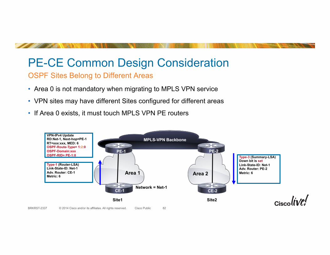
PE-CE Common Design Consideration
• Area 0 is not mandatory when migrating to MPLS VPN service
• VPN sites may have different Sites configured for different areas
• If Area 0 exists, it must touch MPLS VPN PE routers
OSPF Sites Belong to Different Areas
82
Area 2
Network = Net-1
Type-3 (Summary-LSA) Down bit is set Link-State-ID: Net-1 Adv. Router: PE-2 Metric: 6
Site1 Site2
Area 1
Type-1 (Router-LSA) Link-State-ID: Net-1 Adv. Router: CE-1 Metric: 6
VPN-IPv4 Update RD:Net-1, Next-hop=PE-1 RT=xxx:xxx, MED: 6 OSPF-Route-Type= 1:2:0 OSPF-Domain:xxx OSPF-RID= PE-1:0
MPLS-VPN Backbone
PE-1 PE-2
CE-2 CE-1

© 2014 Cisco and/or its affiliates. All rights reserved. BRKRST-2337 Cisco Public
Area 1
PE-CE Common Design Consideration
• All sites belong to same OSPF area (area 1 in the example)
• PEs acts as OSPF ABR routers (Type1 or 2 LSA are always converted into Type 3)
• Remote Site receives a summary LSA
• Not an issue if the topology for simple topologies
All Sites Belong to the Same Area—Backdoor Does Not Exist
83
Area 1
Type-3 LSA created even though local area number is same
Type-3 (Summary-LSA) Down bit is set Link-State-ID: Net-1 Adv. Router: PE-2 Metric: 6
Network = Net-1
Site1 Site2
Type-1 (Router-LSA) Link-State-ID: Net-1 Adv. Router: CE-1 Metric: 6
VPN-IPv4 Update RD:Net-1, Next-hop=PE-1 RT=xxx:xxx, MED: 6 OSPF-Route-Type= 1:2:0 OSPF-Domain:xxx OSPF-RID= PE-1:0
MPLS-VPN Backbone
PE-1 PE-2
CE-2 CE-1

© 2014 Cisco and/or its affiliates. All rights reserved. BRKRST-2337 Cisco Public
PE-CE Common Design Consideration
• Route is advertised to MPLS VPN backbone
• Same prefix is learnt as intra-area route via backdoor link
• PE2 does not generate Type3 LSA once type-1 LSA is received from the site
• Traffic is sent over backdoor link instead of MPLS VPN cloud
All Sites Belong to the Same Area—Backdoor Exists
84
Type-1 (Router-LSA) Link-State-ID: C-1 Link-ID: Net-1 Area: 1, Adv. Router: C-1 C-1
Type-1 (Router-LSA) Link-State-ID: C-1 Link-ID: Net-1 Area: 1 Adv. Router: C-1
Type-1 (Router-LSA) Link-State-ID: C-1 Link-ID: Net-1 Area: 1, Adv. Router: C-1
Type-1 (Router-LSA) Link-State-ID: C-1 Link-ID: Net-1 Area: 1, Adv. Router: C-1
MPLS-VPN Backbone
PE-1 PE-2
CE-2 CE-1 Area 1
Area 1
VPN-IPv4 Update RD:Net-1, Next-hop=PE-1 RT=xxx:xxx OSPF-Route-Type= 1:2:0 OSPF-Domain: xxx OSPF-RID= PE-1:0
No LSA Type 3 created MPLS VPN backbone not used

© 2014 Cisco and/or its affiliates. All rights reserved. BRKRST-2337 Cisco Public
MPLS-VPN Backbone
PE-1
CE-2 CE-1
PE-CE Common Design Consideration:
• The sham link is treated as a virtual-link: unnumbered, point-to-point, DC link
• The sham link is reported in the router LSA’s Type 1 originated by the two routers connecting to the sham link
• The MPLS VPN backbone or the backdoor link can be made preferred path by tweaking the metrics
Sites Belong to the Same Area—Backdoor with Sham Link
85
Type-1 (Router-LSA) Link-State-ID: C-1 Link-ID: Net-1 Area: 1 Adv. Router: C-1
Sham-Link
PE- Type-1 (Router-LSA) Link-State-ID: C-1 Link-ID: Net-1 Area: 1, Adv. Router: C-1
Type-1 (Router-LSA) Link-State-ID: C-1 Link-ID: Net-1 Area: 1, Adv. Router: C-1
Type-1 (Router-LSA) Link-State-ID: C-1 Link-ID: Net-1 Area: 1, Adv. Router: C-1
C-1 CE-1/CE-2 link
Area 1
Type-1 (Router-LSA) Link-State-ID: C-1 Link-ID: Net-1 Area: 1, Adv. Router: C-1

© 2014 Cisco and/or its affiliates. All rights reserved. BRKRST-2337 Cisco Public
PE-CE Common Design Consideration:
• Some OSPF sites entirely belong to area 0 and some other sites can belong to non-area 0
• Some sites may consist of hierarchical OSPF topology consisting of area 0 in additon to non-area 0
• Both scenarios are valid
Other Scenarios for Area Placement
86
PE1 PE2
CE1
MPLS VPN Super Backbone
Area 1 VPN red Area 0
VPN red
Area 2
© 2014 Cisco and/or its affiliates. All rights reserved. BRKRST-2337 Cisco Public
virtual-link
PE-CE Common Design Consideration
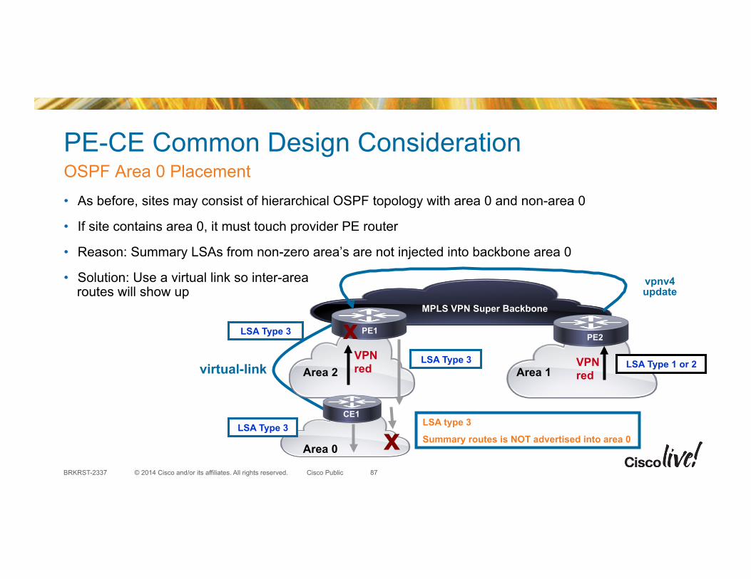
• As before, sites may consist of hierarchical OSPF topology with area 0 and non-area 0
• If site contains area 0, it must touch provider PE router
• Reason: Summary LSAs from non-zero area’s are not injected into backbone area 0
• Solution: Use a virtual link so inter-area routes will show up
OSPF Area 0 Placement
87
MPLS VPN Super Backbone
Area 1 VPN red Area 2
VPN red LSA Type 1 or 2
vpnv4 update
LSA Type 3
Area 0
LSA type 3
Summary routes is NOT advertised into area 0 x
LSA Type 3 x
LSA Type 3
PE1 PE2
CE1

© 2014 Cisco and/or its affiliates. All rights reserved. BRKRST-2337 Cisco Public
Database Overload Protection • PE protected from being overloaded by CE due to large number of received LSAs
• Router tracks the number of received (non self-generated) LSAs
• Maximum and threshold values can be configured
• Only the misbehaving VRF is affected, other works OK
88
MPLS VPN
RR

© 2014 Cisco and/or its affiliates. All rights reserved. BRKRST-2337 Cisco Public
Database Overload Protection
• If threshold value is reached, error message is logged (40)
• If maximum value is exceeded, no more new LSAs are accepted (50)
• If LSA count does not decrease below the max value (50) within one minute; we enter ‘ignore-state’
• In ‘ignore-state’ all adjacencies are taken down and are not formed for ‘ignored-interval’ (40)
• Once the ‘ignored-interval’ (40) ends, we return to normal operations
• We keep the count on how many times we entered ‘ignore-state’—‘ignore-count’ (6)
• Ignore-count is reset to 0, when we do not exceed maximum number of received LSAs for a ‘reset-time’ (120)
• If ‘ignore-count’ (6) exceeds its configured value, OSPF stays in the ‘ignore state’ permanently
• The only way how to get from the permanent ignore-state is by manually clearing the OSPF process
Example
89

© 2014 Cisco and/or its affiliates. All rights reserved. BRKRST-2337 Cisco Public
Database Overload Protection (CLI)
• Router mode – max-lsa <max> [<threshold> [warning-only]
[ignore-time <value>] [ignore-count <value> [reset-time <value>]]
• Available in: – 12.3(7)T 12.2(25)S 12.0(27)S – 12.2(18)SXE 12.2(27)SBC
• With CSCsd20451 deployable without flapping of all neighbors; available in 12.2(33)SXH, 12.2(33)SRC, 12.5
90

© 2014 Cisco and/or its affiliates. All rights reserved. BRKRST-2337 Cisco Public
OSPF Limit on Number of Redistributed Routes
• Maximum number of prefixes (routes) that are allowed to be redistributed into OSPF from other protocols (or other OSPF processes)
• Self-originated LSAs are limited, Summarized prefixes counted
• Type-7 to Type -5 translated prefixes not counted
91
iBGP OSPF
§ PE protected from being overloaded from BGP
redistribute maximum-prefix maximum [threshold] [warning-only]
MPLS VPN
RR

© 2014 Cisco and/or its affiliates. All rights reserved. BRKRST-2337 Cisco Public
Summary: What Have We Learned?
• OSPFv3 has almost similar features as OSPF and similar deployment techniques can be deployed in IPv6 environment
• Scalability of OSPF is very important factor in modern networks deployment
• Understand OSPF fast convergence and resiliency techniques
• Full mesh and hub and spoke environment needs extra tuning in OSPF
• Fast Convergence is almost always required but we should be careful when deploying fast Convergence with NSF
• Lot of things need to be consider when deploying OSPF as a PE CE protocol
92

© 2014 Cisco and/or its affiliates. All rights reserved. BRKRST-2337 Cisco Public
Recommended Reading for BRKRST-2337
93
Source: Cisco Press®

© 2014 Cisco and/or its affiliates. All rights reserved. BRKRST-2337 Cisco Public
Participate in the “My Favorite Speaker” Contest
• Promote your favorite speaker through Twitter and you could win $200 of Cisco Press products (@CiscoPress)
• Send a tweet and include – Your favorite speaker’s Twitter handle @sshamim and @diivious – Two hashtags: #CLUS #MyFavoriteSpeaker
• You can submit an entry for more than one of your “favorite” speakers
• Don’t forget to follow @CiscoLive and @CiscoPress
• View the official rules at http://bit.ly/CLUSwin
Promote Your Favorite Speaker and You Could be a Winner
94

© 2014 Cisco and/or its affiliates. All rights reserved. BRKRST-2337 Cisco Public
Complete Your Online Session Evaluation
• Give us your feedback and you could win fabulous prizes. Winners announced daily.
• Complete your session evaluation through the Cisco Live mobile app or visit one of the interactive kiosks located throughout the convention center.
Don’t forget: Cisco Live sessions will be available for viewing on-demand after the event at CiscoLive.com/Online
95

© 2014 Cisco and/or its affiliates. All rights reserved. BRKRST-2337 Cisco Public
Continue Your Education
• Demos in the Cisco Campus
• Walk-in Self-Paced Labs
• Table Topics
• Meet the Engineer 1:1 meetings
96

