network os layer 3 - hitachi data systems · ospfv3.....63 ospfv3 overview.....63 ospfv3 ......
TRANSCRIPT
53-1003771-0125 June 2015
Network OS Layer 3Routing Configuration Guide
Supporting Network OS v6.0.1
MK-99COM162-00

© 2015, Brocade Communications Systems, Inc. All Rights Reserved.
ADX, Brocade, Brocade Assurance, the B-wing symbol, DCX, Fabric OS, HyperEdge, ICX, MLX, MyBrocade, OpenScript, The EffortlessNetwork, VCS, VDX, Vplane, and Vyatta are registered trademarks, and Fabric Vision and vADX are trademarks of BrocadeCommunications Systems, Inc., in the United States and/or in other countries. Other brands, products, or service names mentioned may betrademarks of others.
Notice: This document is for informational purposes only and does not set forth any warranty, expressed or implied, concerning anyequipment, equipment feature, or service offered or to be offered by Brocade. Brocade reserves the right to make changes to this documentat any time, without notice, and assumes no responsibility for its use. This informational document describes features that may not becurrently available. Contact a Brocade sales office for information on feature and product availability. Export of technical data contained inthis document may require an export license from the United States government.
The authors and Brocade Communications Systems, Inc. assume no liability or responsibility to any person or entity with respect to theaccuracy of this document or any loss, cost, liability, or damages arising from the information contained herein or the computer programs thataccompany it.
The product described by this document may contain open source software covered by the GNU General Public License or other opensource license agreements. To find out which open source software is included in Brocade products, view the licensing terms applicable tothe open source software, and obtain a copy of the programming source code, please visit http://www.brocade.com/support/oscd.

Contents
Preface...................................................................................................................................11Document conventions....................................................................................11
Text formatting conventions................................................................ 11Command syntax conventions............................................................ 11Notes, cautions, and warnings............................................................ 12
Brocade resources.......................................................................................... 13Contacting Brocade Technical Support...........................................................13Document feedback........................................................................................ 14
About this document...............................................................................................................15Supported hardware and software.................................................................. 15Using the Network OS CLI ............................................................................. 16What’s new in this document.......................................................................... 16
IP Route Policy........................................................................................................................17IP route policy overview.................................................................................. 17
IP prefix lists........................................................................................17Route maps.........................................................................................17
Configuring IP route policy.............................................................................. 18
IP Route Management.............................................................................................................21IP route management overview...................................................................... 21
How IP route management determines best route..............................21Managing ECMP global configurations............................................... 21
Configuring static routes................................................................................. 22Specifying the next-hop gateway........................................................ 22Specifying the egress interface........................................................... 22Configuring the default route...............................................................22
BFD for static routes....................................................................................... 23BFD considerations and limitations for static routes........................... 23BFD for static routes configuration......................................................24Configuring BFD on an IP static route.................................................25Configuring BFD on an IP static route in a nondefault VRF................26Configuring BFD on an IPv6 static route.............................................27Configuring BFD on an IPv6 static route in a nondefault VRF............ 27
PBR........................................................................................................................................29Policy-Based Routing......................................................................................29Policy-Based Routing behavior....................................................................... 30Policy-Based Routing with differing next hops................................................ 31Policy-Based Routing uses of NULL0............................................................. 32
Policy-Based Routing and NULL0 with match statements..................32Policy-Based Routing and NULL0 as route map default action.......... 33
PIM.........................................................................................................................................35
Network OS Layer 3 Routing Configuration Guide 353-1003771-01
Protocol-independent multicast (PIM) overview............................................35PIM prerequisites.............................................................................. 35PIM considerations and limitations ...................................................35PIM-standards conformity................................................................. 36
PIM-sparse overview ....................................................................................36PIM-sparse device types...................................................................37PIM-sparse topologies ..................................................................... 37
Configuring PIM-sparse................................................................................ 40PIM-sparse configuration notes........................................................ 40Graphic guide to PIM-sparse configuration.......................................40Enabling IGMP snooping on access-layer switches......................... 42Enabling PIM on aggregation-layer switches....................................42Restricting unknown multicast...........................................................43
OSPF.................................................................................................................................... 45OSPF overview............................................................................................. 45
Autonomous System.........................................................................45OSPF components and roles............................................................46OSPF areas...................................................................................... 48Virtual links........................................................................................50OSPFv2 graceful restart....................................................................51OSPF over VRF................................................................................ 52OSPF in a VCS environment............................................................ 52OSPF considerations and limitations................................................ 53
Configuring OSPF.........................................................................................54Performing basic OSPF configuration...............................................54Disabling OSPFv2 graceful restart....................................................57Re-enabling OSPFv2 graceful restart............................................... 57Disabling OSPFv2 graceful restart helper.........................................58OSPFv2 non-stop routing (NSR).......................................................59Configuring the OSPFv2 Max-Metric Router LSA.............................59Enabling OSPF over VRF................................................................. 60Enabling OSPF in a VCS environment............................................. 60Changing default settings..................................................................61Disabling and re-enabling OSPFv2 event logging............................ 61Disabling OSPF on the router........................................................... 62
OSPFv3.................................................................................................................................63OSPFv3 overview......................................................................................... 63OSPFv3 considerations and limitations........................................................ 64OSPFv3 areas...............................................................................................64
Backbone area..................................................................................64Area types.........................................................................................65Area range........................................................................................ 65Stub area...........................................................................................65Totally stubby area............................................................................66Not-so-stubby area............................................................................66LSA types for OSPFv3......................................................................67
Virtual links....................................................................................................67Virtual link source address assignment.............................................69
OSPFv3 route redistribution..........................................................................69Default route origination................................................................................70Filtering OSPFv3 routes................................................................................71SPF timers.................................................................................................... 71OSPFv3 administrative distance...................................................................71OSPFv3 LSA refreshes.................................................................................72
4 Network OS Layer 3 Routing Configuration Guide53-1003771-01
OSPFv3 over VRF.......................................................................................... 72OSPFv3 graceful restart helper.......................................................................73OSPFv3 non-stop routing (NSR).....................................................................73IPsec for OSPFv3........................................................................................... 73IPsec for OSPFv3 configuration......................................................................75Configuring OSPFv3....................................................................................... 75
Configuring the router ID.....................................................................75Enabling OSPFv3................................................................................76Enabling OSPFv3 in a nondefault VRF...............................................76Assigning OSPFv3 areas.................................................................... 77Assigning OSPFv3 areas in a nondefault VRF................................... 77Assigning OSPFv3 areas to interfaces............................................... 78Configuring an NSSA.......................................................................... 79Assigning a stub area..........................................................................80Configuring virtual links....................................................................... 80Redistributing routes into OSPFv3......................................................81Modifying Shortest Path First timers................................................... 82Configuring the OSPFv3 LSA pacing interval..................................... 83Configuring default route origin........................................................... 83Disabling and re-enabling OSPFv3 event logging.............................. 84Configuring administrative distance based on route type................... 84Changing the reference bandwidth for the cost on OSPFv3...............85Setting all OSPFv3 interfaces to the passive state............................. 86Disabling OSPFv3 graceful restart helper...........................................86Re-enabling OSPFv3 graceful restart helper...................................... 87Configuring the OSPFv3 max-metric router LSA................................ 87Configuring IPsec on an OSPFv3 area............................................... 88Configuring IPsec on an OSPFv3 interface........................................ 89Configuring IPsec on OSPFv3 virtual links......................................... 89Specifying the key rollover and key add-remove timers......................90Displaying OSPFv3 results................................................................. 91Clearing OSPFv3 redistributed routes................................................ 94
BGP........................................................................................................................................97BGP overview................................................................................................. 97
BGP support........................................................................................97Deployment scenarios.........................................................................97BGP peering......................................................................................100BGP attributes...................................................................................103Best-path algorithm........................................................................... 103BGP limitations and considerations.................................................. 104
Understanding BGP configuration fundamentals.......................................... 104Configuring BGP............................................................................... 105Device ID...........................................................................................105Local AS number...............................................................................105IPv4 unicast address family.............................................................. 105BGP global mode ............................................................................. 106Neighbor configuration...................................................................... 107Peer groups.......................................................................................108Four-byte AS numbers...................................................................... 108Route redistribution........................................................................... 109Advertised networks..........................................................................109Static networks..................................................................................109Route reflection................................................................................. 110Route flap dampening....................................................................... 110Default route origination.................................................................... 111Multipath load sharing....................................................................... 111
Network OS Layer 3 Routing Configuration Guide 553-1003771-01
Configuring the default route as a valid next-hop........................... 111Next-hop recursion..........................................................................112Route filtering..................................................................................112Timers............................................................................................. 112BGP4 outbound route filtering.........................................................112BGP4 confederations......................................................................113BGP4 extended community............................................................ 113BGP4+ graceful restart................................................................... 113Using route maps............................................................................114
Configuring BGP......................................................................................... 117Adjusting defaults to improve routing performance.........................117Configuring BGP4 outbound route filtering..................................... 118Configuring BGP4 confederations.................................................. 119Defining BGP4 extended communities........................................... 120Applying a BGP4 extended community filter...................................121Configuring BGP4 graceful restart.................................................. 122Using route maps with match and set statements.......................... 123Clearing configurations................................................................... 126Displaying BGP4 statistics.............................................................. 127
BGP4+............................................................................................................................... 129BGP4+ overview......................................................................................... 129BGP global mode .......................................................................................129IPv6 unicast address family........................................................................ 130BGP4+ neighbors........................................................................................131BGP4+ peer groups.................................................................................... 131BGP4+ next hop recursion..........................................................................132BGP4+ NLRIs and next hop attributes........................................................132BGP4+ route reflection................................................................................133BGP4+ route aggregation........................................................................... 133BGP4+ multipath.........................................................................................133Route maps.................................................................................................134BGP4+ outbound route filtering...................................................................134BGP4+ confederations................................................................................134BGP4+ extended community...................................................................... 135BGP4+ graceful restart............................................................................... 135Configuring BGP4+..................................................................................... 135
Configuring BGP4+ neighbors using global IPv6 addresses.......... 136Configuring BGP4+ neighbors using link-local addresses.............. 136Configuring BGP4+ peer groups.....................................................137Configuring a peer group with IPv4 and IPv6 peers....................... 138Importing routes into BGP4+...........................................................139Advertising the default BGP4+ route...............................................140Advertising the default BGP4+ route to a specific neighbor............140Using the IPv6 default route as a valid next hop for a BGP4+
route.......................................................................................... 141Enabling next-hop recursion........................................................... 142Configuring a cluster ID for a route reflector................................... 142Configuring a route reflector client.................................................. 143Aggregating routes advertised to BGP neighbors...........................143Enabling load-balancing across different paths.............................. 144Configuring a route map for BGP4+ prefixes.................................. 145Redistributing prefixes into BGP4+................................................. 146Configuring BGP4+ outbound route filtering................................... 146Configuring BGP4+ confederations................................................ 148Defining BGP4+ extended communities......................................... 148Applying a BGP4+ extended community filter.................................149
6 Network OS Layer 3 Routing Configuration Guide53-1003771-01
Configuring BGP4+ graceful restart.................................................. 150Disabling the BGP AS_PATH check function................................... 152Displaying BGP4+ statistics.............................................................. 153Displaying BGP4+ neighbor statistics............................................... 155Clearing BGP4+ dampened paths.................................................... 156
VRRP....................................................................................................................................159VRRPv2 Overview........................................................................................ 159
VRRP Terminology........................................................................... 161VRRP-Ev2 overview..........................................................................162VRRPv2 limitations on Brocade VDX devices.................................. 162VRRP hold timer............................................................................... 163VRRP interval timers.........................................................................163ARP and VRRP control packets........................................................163
Enabling a master VRRP device...................................................................164Enabling a backup VRRP device.................................................................. 165Enabling a VRRP-E device........................................................................... 166VRRP multigroup clusters............................................................................. 167
Configuring multigroup VRRP routing............................................... 168Track ports and track priority with VRRP and VRRP-E.................................170
Tracking ports and setting VRRP priority.......................................... 170Track routes and track priority with VRRP-E.................................................172
Tracking routes and setting VRRP-E priority.................................... 172VRRP backup preemption.............................................................................173
Enabling VRRP backup preemption..................................................174VRRP-E load-balancing using short-path forwarding....................................174
Short-path forwarding with revert priority.......................................... 176Configuring VRRP-E load-balancing in VCS mode...........................176
Clearing VRRPv2 statistics........................................................................... 177Displaying VRRPv2 information.................................................................... 178
VRRPv3................................................................................................................................ 181VRRPv3 overview......................................................................................... 181
VRRPv3 functionality differences on Brocade VDX devices.............182VRRPv3 performance and scalability metrics for Network OS
devices........................................................................................ 182Enabling IPv6 VRRPv3................................................................................. 182Enabling IPv4 VRRPv3................................................................................. 183Enabling IPv6 VRRP-Ev3..............................................................................184Track ports and track priority with VRRP and VRRP-E.................................185
Port tracking using IPv6 VRRPv3..................................................... 186Track routes and track priority with VRRP-E.................................................187
Tracking routes and setting IPv6 VRRP-Ev3 priority........................ 188VRRP hold timer........................................................................................... 189
Configuring VRRP hold timer support............................................... 189VRRP-E load-balancing using short-path forwarding....................................190
Short-path forwarding with revert priority.......................................... 191Configuring VRRP-Ev3 load-balancing in VCS mode.......................192
VRRP-Ev3 sub-second failover.....................................................................193Configuring sub-second failover using VRRP-Ev3............................193
VRRPv3 router advertisement suppression.................................................. 194Disabling VRRPv3 router advertisements.........................................194
Alternate VRRPv2 checksum for VRRPv3 IPv4 sessions.............................195Enabling the v2 checksum computation method in a VRRPv3
IPv4 session................................................................................ 195Displaying VRRPv3 statistics........................................................................ 196
Network OS Layer 3 Routing Configuration Guide 753-1003771-01
Clearing VRRPv3 statistics......................................................................... 198
BFD....................................................................................................................................201Bidirectional Forwarding Detection (BFD)...................................................201General BFD considerations and limitations...............................................202BFD on Network OS hardware platforms....................................................202BFD for Layer 3 protocols........................................................................... 204BFD considerations and limitations for Layer 3 protocols...........................205BFD for Layer 3 protocols on virtual Ethernet interfaces............................ 206BFD for Layer 3 protocols on vLAGs.......................................................... 207Configuring BFD on an interface.................................................................207Disabling BFD on an interface.................................................................... 208BFD for BGP............................................................................................... 208
BFD for BGP session creation and deletion................................... 209Configuring BFD session parameters for BGP............................... 210Enabling BFD sessions for a specified BGP neighbor....................210Enabling BFD sessions for a specified BGP neighbor in a
nondefault VRF..........................................................................211Enabling BFD sessions for a specified BGP peer group................ 212Enabling BFD sessions for a specified BGP peer group in a
nondefault VRF..........................................................................212BFD for OSPF.............................................................................................213
BFD for OSPF session creation and deletion................................. 214Enabling BFD on a specified OSPFv2-enabled interface............... 214Configuring BFD for OSPFv2 globally.............................................215Configuring BFD for OSPFv2 globally in a nondefault VRF
instance..................................................................................... 215Enabling BFD on a specified OSPFv3-enabled interface............... 216Configuring BFD for OSPFv3 globally.............................................216Configuring BFD for OSPFv3 globally in a nondefault VRF
instance..................................................................................... 217BFD for VXLAN extension tunnels..............................................................218
Configuring BFD on a VXLAN extension tunnel............................. 220BFD for NSX tunnels...................................................................................221BFD for static routes................................................................................... 222
BFD considerations and limitations for static routes....................... 222BFD for static routes configuration..................................................223Configuring BFD on an IP static route.............................................224Configuring BFD on an IP static route in a nondefault VRF............225Configuring BFD on an IPv6 static route.........................................225Configuring BFD on an IPv6 static route in a nondefault VRF........226
Displaying BFD information.........................................................................226
Fabric-Virtual-Gateway....................................................................................................... 231Fabric-Virtual-Gateway overview................................................................ 231Fabric-Virtual-Gateway limitations.............................................................. 232Gateway behavior per RBridge...................................................................232Fabric-Virtual-Gateway configuration notes................................................233Fabric-Virtual-Gateway configuration..........................................................235
Enabling and configuring Fabric-Virtual-Gateway globally (IPv4)...237Enabling and configuring Fabric-Virtual-Gateway globally (IPv6)...238Configuring Fabric-Virtual-Gateway on a VE interface (IPv4).........239Configuring Fabric-Virtual-Gateway on a VE interface (IPv6).........241Configuring Fabric-Virtual-Gateway on an RBridge VE interface
(IPv4).........................................................................................242
8 Network OS Layer 3 Routing Configuration Guide53-1003771-01
Configuring Fabric-Virtual-Gateway on an RBridge VE interface(IPv6)........................................................................................... 243
Troubleshooting Fabric-Virtual-Gateway...........................................244
Virtual Routing and Forwarding............................................................................................. 247VRF overview................................................................................................247
VRF topology.................................................................................... 247Configuring VRF ...........................................................................................248
Enabling VRRP for VRF....................................................................249Inter-VRF route leaking................................................................................. 250
Configuring Static Inter-VRF route leaking........................................252Configuring Dynamic Inter-VRF route leaking...................................254
Understanding and using management services in default-vrf and mgmt-vrf.............................................................................................................257
Configuring management VRFs........................................................258Managing management VRFs.......................................................... 259
Multi-VRF............................................................................................................................. 261Multi-VRF overview....................................................................................... 261Configuring basic Multi-VRF functionality..................................................... 262
Multi-VRF with eBGP and OSPF...................................................... 263Multi-VRF with OSPF........................................................................ 269
IPv4 DHCP Relay...................................................................................................................275DHCP protocol.............................................................................................. 275IP DHCP Relay function................................................................................275Brocade IP DHCP relay overview................................................................. 276
Supported platforms..........................................................................277Configuring IP DHCP Relay.......................................................................... 277Displaying IP DHCP relay addresses for an interface...................................279Displaying IP DHCP Relay addresses on specific switches......................... 280Displaying IP DHCP Relay statistics............................................................. 281Clearing IP DHCP Relay statistics................................................................ 282VRF support.................................................................................................. 283High Availability support................................................................................284
IPv6 DHCP Relay...................................................................................................................285DHCPv6 relay agent..................................................................................... 285DHCPv6 multicast addresses and UDP ports...............................................286DHCPv6 address assignment....................................................................... 287DHCPv6 message format............................................................................. 288DHCPv6 relay provisioning........................................................................... 289Configuring IPv6 DHCP Relay...................................................................... 290Displaying DHCPv6 Relay addresses on a specific switch...........................291Displaying DHCPv6 Relay addresses for an interface..................................292Displaying IPv6 DHCP Relay statistics......................................................... 293Clearing IP DHCPv6 Relay statistics............................................................ 294
Dual-Stack Support.............................................................................................................. 295Understanding dual-stack support................................................................ 295Configuring IPv6 addressing and connectivity.............................................. 297
Understanding IPv6 addresses and prefixes.................................... 297
Network OS Layer 3 Routing Configuration Guide 953-1003771-01
Configuring a global IPv6 address with a manually configuredinterface ID................................................................................ 298
Configuring a global IPv6 address with an automaticallycomputed EUI-64 interface ID................................................... 299
Configuring a link-local IPv6 address..............................................299Configuring an IPv6 anycast address............................................. 300Configuring IPv4 and IPv6 protocol stacks..................................... 300Configuring an IPv6 address family ............................................... 301Configuring static IPv6 routes......................................................... 301Changing the IPv6 MTU..................................................................303
Configuring IPv6 Neighbor Discovery......................................................... 304Neighbor Solicitation and Neighbor Advertisement messages....... 305Router Advertisement and Router Solicitation messages...............305Neighbor Redirect messages..........................................................306Duplicate address detection (DAD).................................................306Setting Neighbor Solicitation parameters for DAD..........................307Configuring IPv6 static neighbor entries......................................... 308Setting IPv6 Router Advertisement parameters..............................308Controlling prefixes advertised in IPv6 Router Advertisement
messages.................................................................................. 308Setting flags in IPv6 Router Advertisement messages................... 309
Configuring MLD snooping......................................................................... 310Enabling and disabling MLD snooping globally.............................. 311Enabling and disabling MLD snooping at the interface level.......... 312Enabling and disabling MLD querier functionality on a VLAN.........312Configuring and unconfiguring an MLD static group on a VLAN.... 312Enabling and disabling MLD fast-leave on a VLAN........................ 313Configuring the MLD query interval.................................................313Configuring the MLD last-member query interval............................313Configuring the MLD last-member query count.............................. 314Configuring the MLD query maximum response time.....................314Configuring the MLD snooping robustness variable....................... 315Configuring the MLD startup query count....................................... 315Configuring the MLD startup query interval.................................... 315Configuring a VLAN port member to be a multicast router port...... 316Managing the flooding of multicast data traffic................................316Monitoring and managing MLD snooping....................................... 316
Monitoring and managing IPv6 networks....................................................317
10 Network OS Layer 3 Routing Configuration Guide53-1003771-01
Preface
● Document conventions....................................................................................................11● Brocade resources.......................................................................................................... 13● Contacting Brocade Technical Support...........................................................................13● Document feedback........................................................................................................ 14
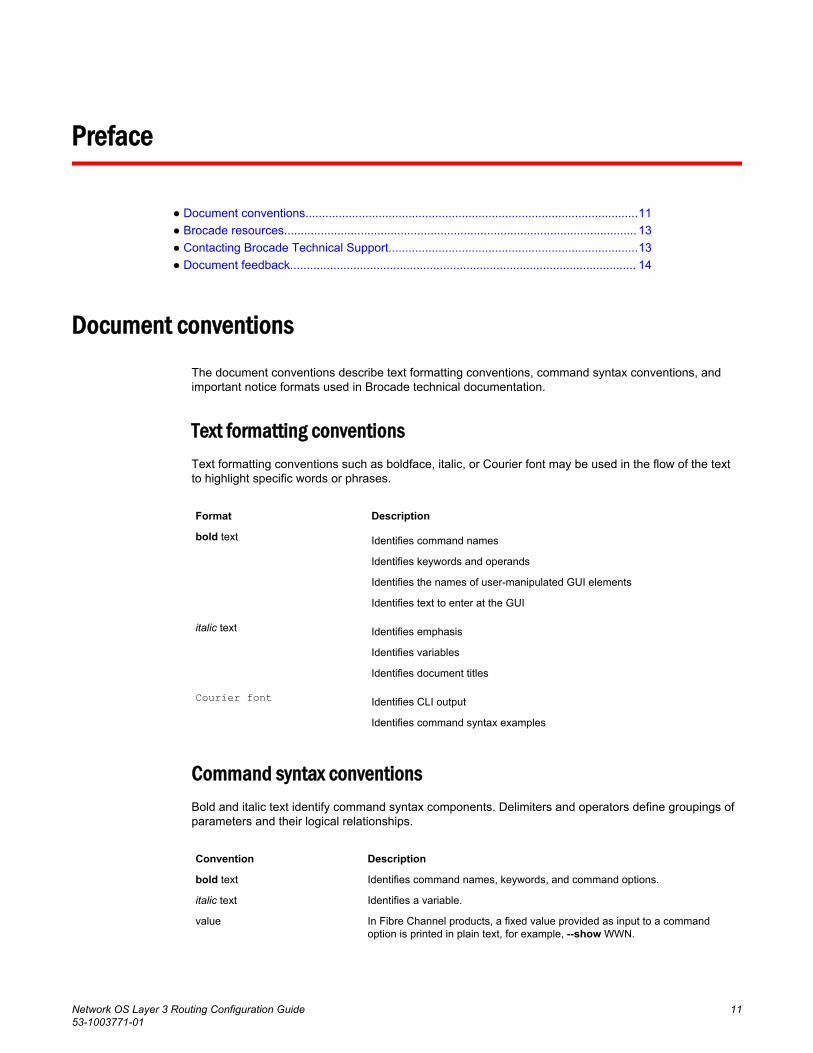
Document conventionsThe document conventions describe text formatting conventions, command syntax conventions, andimportant notice formats used in Brocade technical documentation.
Text formatting conventionsText formatting conventions such as boldface, italic, or Courier font may be used in the flow of the textto highlight specific words or phrases.
Format Description
bold text Identifies command names
Identifies keywords and operands
Identifies the names of user-manipulated GUI elements
Identifies text to enter at the GUI
italic text Identifies emphasis
Identifies variables
Identifies document titles
Courier font Identifies CLI output
Identifies command syntax examples
Command syntax conventionsBold and italic text identify command syntax components. Delimiters and operators define groupings ofparameters and their logical relationships.
Convention Description
bold text Identifies command names, keywords, and command options.
italic text Identifies a variable.
value In Fibre Channel products, a fixed value provided as input to a commandoption is printed in plain text, for example, --show WWN.
Network OS Layer 3 Routing Configuration Guide 1153-1003771-01
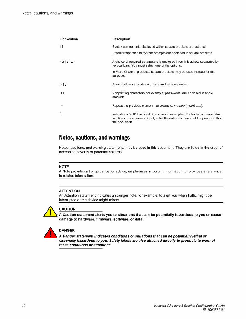
Convention Description
[ ] Syntax components displayed within square brackets are optional.
Default responses to system prompts are enclosed in square brackets.
{ x | y | z } A choice of required parameters is enclosed in curly brackets separated byvertical bars. You must select one of the options.
In Fibre Channel products, square brackets may be used instead for thispurpose.
x | y A vertical bar separates mutually exclusive elements.
< > Nonprinting characters, for example, passwords, are enclosed in anglebrackets.
... Repeat the previous element, for example, member[member...].
\ Indicates a “soft” line break in command examples. If a backslash separatestwo lines of a command input, enter the entire command at the prompt withoutthe backslash.
Notes, cautions, and warningsNotes, cautions, and warning statements may be used in this document. They are listed in the order ofincreasing severity of potential hazards.
NOTEA Note provides a tip, guidance, or advice, emphasizes important information, or provides a referenceto related information.
ATTENTIONAn Attention statement indicates a stronger note, for example, to alert you when traffic might beinterrupted or the device might reboot.
CAUTIONA Caution statement alerts you to situations that can be potentially hazardous to you or causedamage to hardware, firmware, software, or data.
DANGERA Danger statement indicates conditions or situations that can be potentially lethal orextremely hazardous to you. Safety labels are also attached directly to products to warn ofthese conditions or situations.
Notes, cautions, and warnings
12 Network OS Layer 3 Routing Configuration Guide53-1003771-01

Brocade resourcesVisit the Brocade website to locate related documentation for your product and additional Brocaderesources.
You can download additional publications supporting your product at www.brocade.com. Select theBrocade Products tab to locate your product, then click the Brocade product name or image to open theindividual product page. The user manuals are available in the resources module at the bottom of thepage under the Documentation category.
To get up-to-the-minute information on Brocade products and resources, go to MyBrocade. You canregister at no cost to obtain a user ID and password.
Release notes are available on MyBrocade under Product Downloads.
White papers, online demonstrations, and data sheets are available through the Brocade website.
Contacting Brocade Technical SupportAs a Brocade customer, you can contact Brocade Technical Support 24x7 online, by telephone, or by e-mail. Brocade OEM customers contact their OEM/Solutions provider.
Brocade customersFor product support information and the latest information on contacting the Technical AssistanceCenter, go to http://www.brocade.com/services-support/index.html.
If you have purchased Brocade product support directly from Brocade, use one of the following methodsto contact the Brocade Technical Assistance Center 24x7.
Online Telephone E-mail
Preferred method of contact for non-urgent issues:
• My Cases through MyBrocade• Software downloads and licensing
tools• Knowledge Base
Required for Sev 1-Critical and Sev2-High issues:
• Continental US: 1-800-752-8061• Europe, Middle East, Africa, and
Asia Pacific: +800-AT FIBREE(+800 28 34 27 33)
• For areas unable to access tollfree number: +1-408-333-6061
• Toll-free numbers are available inmany countries.
Please include:
• Problem summary• Serial number• Installation details• Environment description
Brocade OEM customersIf you have purchased Brocade product support from a Brocade OEM/Solution Provider, contact yourOEM/Solution Provider for all of your product support needs.
• OEM/Solution Providers are trained and certified by Brocade to support Brocade® products.• Brocade provides backline support for issues that cannot be resolved by the OEM/Solution Provider.
Brocade resources
Network OS Layer 3 Routing Configuration Guide 1353-1003771-01
• Brocade Supplemental Support augments your existing OEM support contract, providing directaccess to Brocade expertise. For more information, contact Brocade or your OEM.
• For questions regarding service levels and response times, contact your OEM/Solution Provider.
Document feedbackTo send feedback and report errors in the documentation you can use the feedback form posted withthe document or you can e-mail the documentation team.
Quality is our first concern at Brocade and we have made every effort to ensure the accuracy andcompleteness of this document. However, if you find an error or an omission, or you think that a topicneeds further development, we want to hear from you. You can provide feedback in two ways:
• Through the online feedback form in the HTML documents posted on www.brocade.com.• By sending your feedback to [email protected].
Provide the publication title, part number, and as much detail as possible, including the topic headingand page number if applicable, as well as your suggestions for improvement.
Document feedback
14 Network OS Layer 3 Routing Configuration Guide53-1003771-01
About this document
● Supported hardware and software.................................................................................. 15● Using the Network OS CLI ............................................................................................. 16● What’s new in this document.......................................................................................... 16
Supported hardware and softwareIn those instances in which procedures or parts of procedures documented here apply to some switchesbut not to others, this guide identifies exactly which switches are supported and which are not.
Although many different software and hardware configurations are tested and supported by BrocadeCommunications Systems, Inc. for Network OS 6.0.1, documenting all possible configurations andscenarios is beyond the scope of this document.
The following hardware platforms are supported by this release of Network OS:
• Brocade VDX 2740
NOTEThe Brocade VDX 2740 is the equivalent of the Lenovo Flex System EN4023 10Gb Scalable Switch.This platform is identified in the system as EN4023.
• Brocade VDX 2746• Brocade VDX 6740
‐ Brocade VDX 6740-48‐ Brocade VDX 6740-64
• Brocade VDX 6740T
‐ Brocade VDX 6740T-48‐ Brocade VDX 6740T-64‐ Brocade VDX 6740T-1G
• Brocade VDX 6940-36Q• Brocade VDX 6940-144S• Brocade VDX 8770
‐ Brocade VDX 8770-4‐ Brocade VDX 8770-8
To obtain information about a Network OS version other than this release, refer to the documentationspecific to that version.
Network OS Layer 3 Routing Configuration Guide 1553-1003771-01
Using the Network OS CLIFor complete instructions and support for using the Network OS v5.0.1 command line interface (CLI),refer to the Network OS Command Reference.
What’s new in this documentThis document is released in conjunction with Network OS 6.0.0 and incorporates minor editorialimprovements. There are no new Layer 3 features for this release.
For complete information, refer to the Network OS Release Notes.
Using the Network OS CLI
16 Network OS Layer 3 Routing Configuration Guide53-1003771-01
IP Route Policy
● IP route policy overview.................................................................................................. 17● Configuring IP route policy.............................................................................................. 18
IP route policy overviewIP route policy controls how routes or IP subnets are transported from one subsystem to anothersubsystem. The IP route policy may perform "permit" or "deny" actions so that matched routes may beallowed or denied to the target subsystem accordingly. Additionally, IP route policy may also be used formodify the characteristics of a matched route and IP subnet pair.
Two types of IP route policies are supported, prefix-list and route-map, as discussed in the followingsections
IP prefix listsAn IP prefix list is identified by its name. Each IP prefix list may consist of one or more instances. Thefollowing is an example of IP prefix list "test", which is configured in RBridge ID configuration mode:device# configdevice(config-rbridge-id-1)#device(config-rbridge-id-1)# ip prefix-list test deny 1.2.0.0/16 ge 17 le 30device(config-rbridge-id-1)# ip prefix-list test permit 1.1.0.0/16 A matching condition of a prefix-list instance contains two portions: (1) an IP subnet prefix and(2) anoptional prefix (mask) length, where ge (greater than or equal to) is the lower limit of the mask length,and le (less than or equal to) is the upper limit of the mask length. If no ge or le is given in an instance,the exact match of subnet prefix length is needed.
In the example above, a route is considered a match for instance 1 if this route is inside subnet1.2.0.0/16 and whose mask length is between 17 and 30. That is, route 1.2.1.0/24 matches but route1.2.1.1/32 does not match because of the difference in mask length.
Similar to a route map, when finding a match, each prefix-list instance is looked at in the order specifiedby its instance ID. The look-up terminates at the first match. A route that does not find a match in theprefix list is denied.
At present, a prefix list is not used by itself. The IP prefix list can be used as part of route-map matchclauses. In this context, permit means “match” this pattern, and deny means “do not match thispattern."
Route mapsA route map is identified by its name. Each route map may consist of one or more instances. Each routemap instance may contain zero or more match clauses, and zero or more set clauses.
At present, a route map instance represents the largest granularity of configuration. That is, the enduser is required to add and delete route maps by means of its instance. For example, when removing aroute map, an end user is required to remove this route-map in all of its instances. A route map instance
Network OS Layer 3 Routing Configuration Guide 1753-1003771-01
may contain more than one match condition. The overall matching condition of the instance is trueonly if all matching conditions are met. The following is an example of a route map:switch# route-map test deny 1 match interface te 0/1switch# route-map test permit 2 match ip next-hop prefix-list pre-test set tag 5000In the example above, route-map test comprises of two instances: instance 1 denies entry for anyroutes whose next-hop interface is te 0/1, and instance 2 allows entry for routes whose next-hopaddress matches the IP subnets specified by prefix-list pre-test (the prefix-list instance is not shown).Additionally, each matched route has its tag set to 5000.
NOTEThe maximum number of OSPF networks that can be advertised and processed in a single area in arouter is limited to 600.
A route map instance does not need to contain a matching condition; its existence implies that thematching condition for this instance is true.
A route map instance may contain more than one set clause. All set clauses are applied to the matchroutes when applicable.
When a route map is applied, each instance is looked at in the order specified by the instance ID. Ifthere is a match, the instance’s action are applied, and its set clauses are applied if the action ispermitted. The search terminates at the first match. A route that does not find a match in a route mapis denied.
Configuring IP route policy
Similar to ACLs, a route map and IP prefix list need to be applied for a specified policy to take effect.The following example applies a route-map to the redistribution of static routes into an OSPF domain.(For complete information on these commands, refer to the Network OS Command Reference.)
To set an IP route policy, perform the following steps in privileged EXEC mode.
1. Enter the router ospf (or router bgp) command to enable the appropriate Layer 3 protocol. Thisexample uses OSPF and creates the route map instance "test."switch# router ospf redistribute static route-map test area 0
2. Enter the ip route command to create the prefix for a static route.switch# ip route 11.11.11.0/24 2.2.2.1
3. Enter the ip route command to create the next hop in the static route. Repeat as needed.switch# ip route 11.11.11.0/24 2.2.2.2
4. Enter the route-map command to create the route map and prefix list instance.switch# route-map test permit 1 match ip address prefix-list pretest
5. Enter the ip prefix-list command in RBridge ID configuration mode to configure the IP prefix listinstance.switch# configswitch(config)# rbridge-id 1switch(config-rbridge-id-1)# ip prefix-list pretest permit 1.1.1.0/24In the example above, when the route-map test permit 1 command executes, only the static route1.1.1.0/24 is exported into the OSPF domain, because there are no matching rules in pretest forroute 11.11.11.0/24. The default action of pretest is deny (there is no match); therefore, the route11.11.11.0/24 is not exported into the OSPF domain.
You can configure the router to permit or deny specific IP addresses explicitly. The router permits allIP addresses by default. If you want permit to remain the default behavior, define individual filters todeny specific IP addresses. If you want to change the default behavior to deny, define individualfilters to permit specific IP addresses. Once you define a filter, the default action for addresses that
Configuring IP route policy
18 Network OS Layer 3 Routing Configuration Guide53-1003771-01

do not match a filter is deny. To change the default action to permit, configure the last filter aspermit any any.
IP Route Policy
Network OS Layer 3 Routing Configuration Guide 1953-1003771-01

Configuring IP route policy
20 Network OS Layer 3 Routing Configuration Guide53-1003771-01
IP Route Management
● IP route management overview...................................................................................... 21● Configuring static routes................................................................................................. 22● BFD for static routes....................................................................................................... 23
IP route management overviewIP route management is the term used to refer to software that manages routes and next hops fromdifferent sources in a routing table, from which the Brocade device selects the best routes for forwardingIP packets. This route management software gets activated automatically at system bootup and doesnot require preconfiguration.
IP route management runs on all platforms configured for Layer 3 and does the following:
• Maintains routes submitted by other protocols.• Supports route redistribution.• Supports router identification.• Selects and synchronizes routes to the forwarding information base (FIB).• Synchronizes the Layer 3 interface to the FIB.• Supports the following Layer 3 interfaces: virtual ethernet (Ve), router port, loopback, and
management.
NOTEIP route management supports both IPv4 and IPv6 routes.
How IP route management determines best routeThe sources of routes that are added into IP route management are the following:
• Dynamic routes from routing protocols. Open Shortest Path First (OSPF) and Border GatewayProtocol (BGP) are both supported.
• Static configured routes: You can add routes directly to the route table. When you add a route to theIP route table, you are creating a static IP route.
• Directly connected routes from interface configuration: When you add an IP interface, the Brocadedevice automatically creates a route for the network.
Administrative distance can be configured for route types other than connected routes. IP routemanagement prefers routes with lower administrative distances.
Managing ECMP global configurationsThe hardware-profile command provides options for managing Equal Cost Multiple Paths (ECMP)globally at the RBridge level.
Up to 32 ECMP paths are supported for Layer 3.
Network OS Layer 3 Routing Configuration Guide 2153-1003771-01
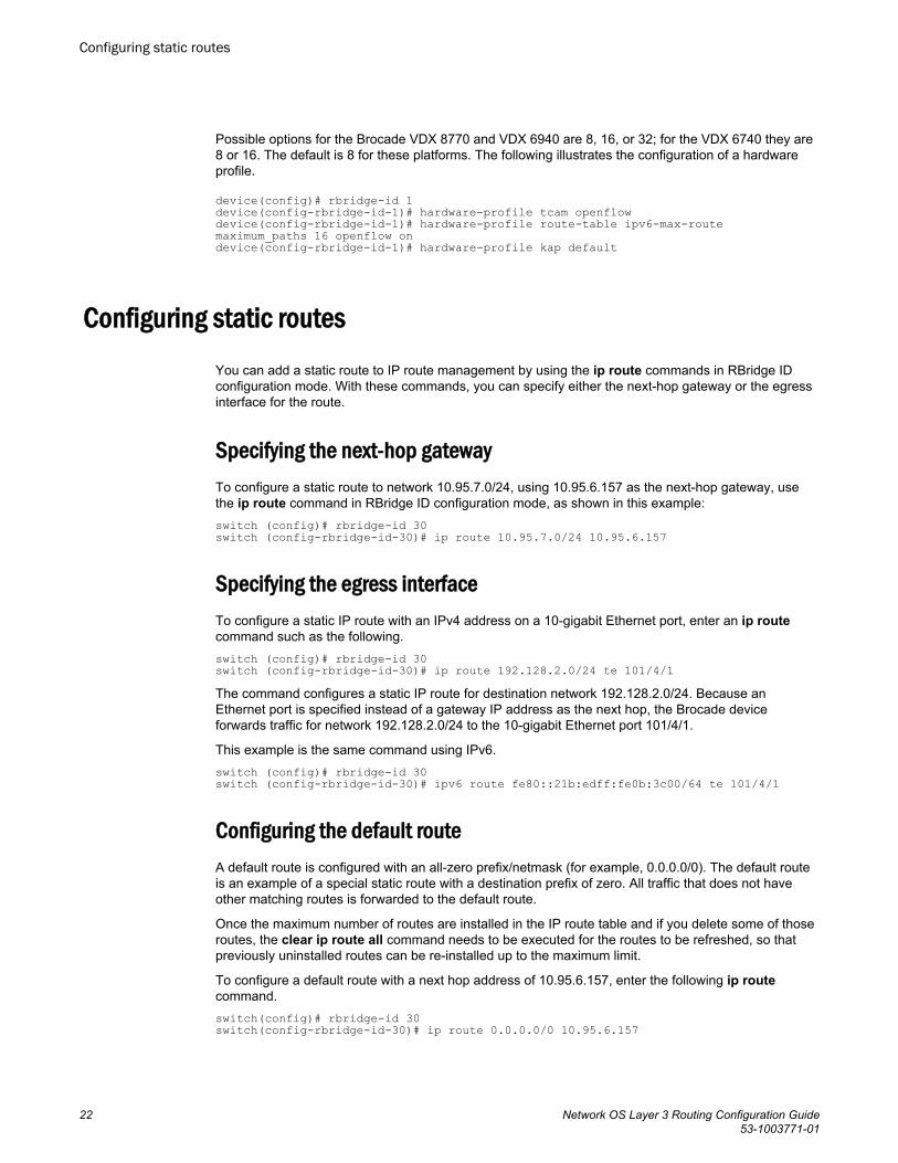
Possible options for the Brocade VDX 8770 and VDX 6940 are 8, 16, or 32; for the VDX 6740 they are8 or 16. The default is 8 for these platforms. The following illustrates the configuration of a hardwareprofile.
device(config)# rbridge-id 1device(config-rbridge-id-1)# hardware-profile tcam openflowdevice(config-rbridge-id-1)# hardware-profile route-table ipv6-max-route maximum_paths 16 openflow ondevice(config-rbridge-id-1)# hardware-profile kap default
Configuring static routesYou can add a static route to IP route management by using the ip route commands in RBridge IDconfiguration mode. With these commands, you can specify either the next-hop gateway or the egressinterface for the route.
Specifying the next-hop gatewayTo configure a static route to network 10.95.7.0/24, using 10.95.6.157 as the next-hop gateway, usethe ip route command in RBridge ID configuration mode, as shown in this example:switch (config)# rbridge-id 30switch (config-rbridge-id-30)# ip route 10.95.7.0/24 10.95.6.157
Specifying the egress interfaceTo configure a static IP route with an IPv4 address on a 10-gigabit Ethernet port, enter an ip routecommand such as the following.switch (config)# rbridge-id 30switch (config-rbridge-id-30)# ip route 192.128.2.0/24 te 101/4/1The command configures a static IP route for destination network 192.128.2.0/24. Because anEthernet port is specified instead of a gateway IP address as the next hop, the Brocade deviceforwards traffic for network 192.128.2.0/24 to the 10-gigabit Ethernet port 101/4/1.
This example is the same command using IPv6.switch (config)# rbridge-id 30switch (config-rbridge-id-30)# ipv6 route fe80::21b:edff:fe0b:3c00/64 te 101/4/1
Configuring the default routeA default route is configured with an all-zero prefix/netmask (for example, 0.0.0.0/0). The default routeis an example of a special static route with a destination prefix of zero. All traffic that does not haveother matching routes is forwarded to the default route.
Once the maximum number of routes are installed in the IP route table and if you delete some of thoseroutes, the clear ip route all command needs to be executed for the routes to be refreshed, so thatpreviously uninstalled routes can be re-installed up to the maximum limit.
To configure a default route with a next hop address of 10.95.6.157, enter the following ip routecommand.switch(config)# rbridge-id 30switch(config-rbridge-id-30)# ip route 0.0.0.0/0 10.95.6.157
Configuring static routes
22 Network OS Layer 3 Routing Configuration Guide53-1003771-01
ATTENTIONFor information about management services that are supported by the management VRF and defaultVRF, refer to Understanding and using management services in default-vrf and mgmt-vrf on page 257.
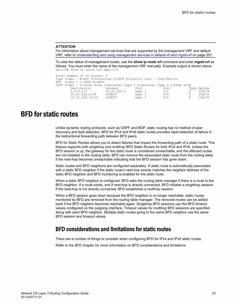
To view the status of management routes, use the show ip route vrf command and enter mgmt-vrf asfollows. You must enter the name of the management VRF manually. Example output is shown below.switch# show ip route vrf mgmt-vrfTotal number of IP routes: 3Type Codes - B:BGP D:Connected O:OSPF S:Static; Cost - Dist/MetricBGP Codes - i:iBGP e:eBGPOSPF Codes - i:Inter Area 1:External Type 1 2:External Type 2 s:Sham Link Destination Gateway Port Cost Type Uptime 0.0.0.0/0 10.25.224.1 mgmt 1 1/1 S 10d17h 10.25.224.0/24 DIRECT mgmt 1 0/0 D 10d17h 10.25.224.18/32 DIRECT mgmt 1 0/0 D 10d17h
BFD for static routesUnlike dynamic routing protocols, such as OSPF and BGP, static routing has no method of peerdiscovery and fault detection. BFD for IPv4 and IPv6 static routes provides rapid detection of failure inthe bidirectional forwarding path between BFD peers.
BFD for Static Routes allows you to detect failures that impact the forwarding path of a static route. Thisfeature supports both singlehop and multihop BFD Static Routes for both IPv4 and IPv6. Unless theBFD session is up, the gateway for the static route is considered unreachable, and the affected routesare not installed in the routing table. BFD can remove the associated static route from the routing tableif the next-hop becomes unreachable indicating that the BFD session has gone down.
Static routes and BFD neighbors are configured separately. A static route is automatically associatedwith a static BFD neighbor if the static route’s next-hop exactly matches the neighbor address of thestatic BFD neighbor and BFD monitoring is enabled for the static route.
When a static BFD neighbor is configured, BFD asks the routing table manager if there is a route to theBFD neighbor. If a route exists, and if next-hop is directly connected, BFD initiates a singlehop session.If the next-hop is not directly connected, BFD establishes a multihop session.
When a BFD session goes down because the BFD neighbor is no longer reachable, static routesmonitored by BFD are removed from the routing table manager. The removed routes can be addedback if the BFD neighbor becomes reachable again. Singlehop BFD sessions use the BFD timeoutvalues configured on the outgoing interface. Timeout values for multihop BFD sessions are specifiedalong with each BFD neighbor. Multiple static routes going to the same BFD neighbor use the sameBFD session and timeout values.
BFD considerations and limitations for static routesThere are a number of things to consider when configuring BFD for IPv4 and IPv6 static routes.
Refer to the BFD chapter for more information on BFD considerations and limitations.
BFD for static routes
Network OS Layer 3 Routing Configuration Guide 2353-1003771-01
BFD considerations and limitations for static routes• BFD is not supported on interface-based static routes because BFD requires that the next-hop
address matches the address of the BFD neighbor.• Only one static route BFD session for a neighbor is created at any instance. This is always based
on the best path for the neighbor.• Static BFD for a multihop BFD neighbor reachable via Equal Cost Multiple Paths (ECMP) is not
supported. Static BFD needs to be configured explicitly for each next-hop corresponding to eachpath.
• When an interface does down, multihop IPv4 static route sessions are not deleted. Multihop IPv6static route sessions are deleted.
• BFD for static routes is supported in both Local-only mode and Distributed mode.• BFD sessions can be singlehop or multihop.• BFD multihop is supported for a nexthop resolved through OSPF or BGP.• If a BFD session goes down and the BFD neighbor had Layer 3 direct connectivity, associated
static routes are removed from the routing table so that data packets can use the available alternatepath.
• If a BFD neighbor is not directly connected and a BFD session goes down, associated static routesare removed only if an alternate path to the neighbor exists.
• BFD for static routes is supported in both default and nondefault VRFs.• BFD for IPv6 static routes is supported in both associated and unassociated mode.• BFD for Link-local IPv6 addresses is supported.• When configuring BFD for Link-local IPv6 static routes, the source IPv6 address must be link-local
and an interface must be provided.
BFD for static routes configuration
Singlehop BFD IPv4 static route sessions use the timer values configured for the outgoing interface tothe directly connected neighbors. Multihop BFD IPv4 static route sessions use the timer valuesconfigured using the ip route static bfd and ip route static bfd holdover-interval commands. If thetimer values configured conflict with the timer values set for BGP for the same next-hop, BFD uses thesmaller value to meet the more stringent requirement.
Singlehop BFD IPv6 static route sessions use the timer values configured for the outgoing interface tothe directly connected neighbors. Multihop BFD IPv6 static route sessions use the timer valuesconfigured using the ipv6 route static bfd and ipv6 route static bfd holdover-interval commands. Ifthe timer values configured conflict with the timer values set for BGP for the same next-hop, BFD usesthe smaller value to meet the more stringent requirement.
If you remove a static BFD session, the corresponding session is removed by BFD without removingstatic routes from the routing table and ongoing traffic is not disrupted. If a BFD session goes downbecause a BFD neighbor is no longer reachable, all associated static routes are removed from therouting table. Existing traffic on these static routes is interrupted.
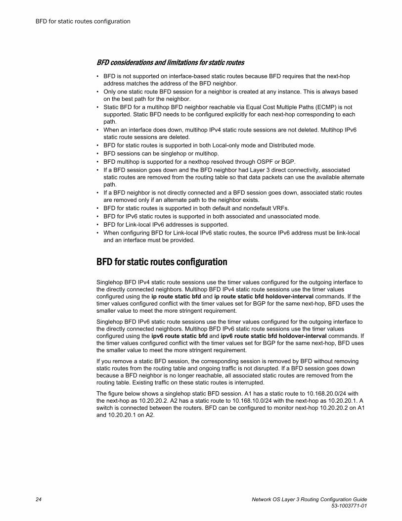
The figure below shows a singlehop static BFD session. A1 has a static route to 10.168.20.0/24 withthe next-hop as 10.20.20.2. A2 has a static route to 10.168.10.0/24 with the next-hop as 10.20.20.1. Aswitch is connected between the routers. BFD can be configured to monitor next-hop 10.20.20.2 on A1and 10.20.20.1 on A2.
BFD for static routes configuration
24 Network OS Layer 3 Routing Configuration Guide53-1003771-01
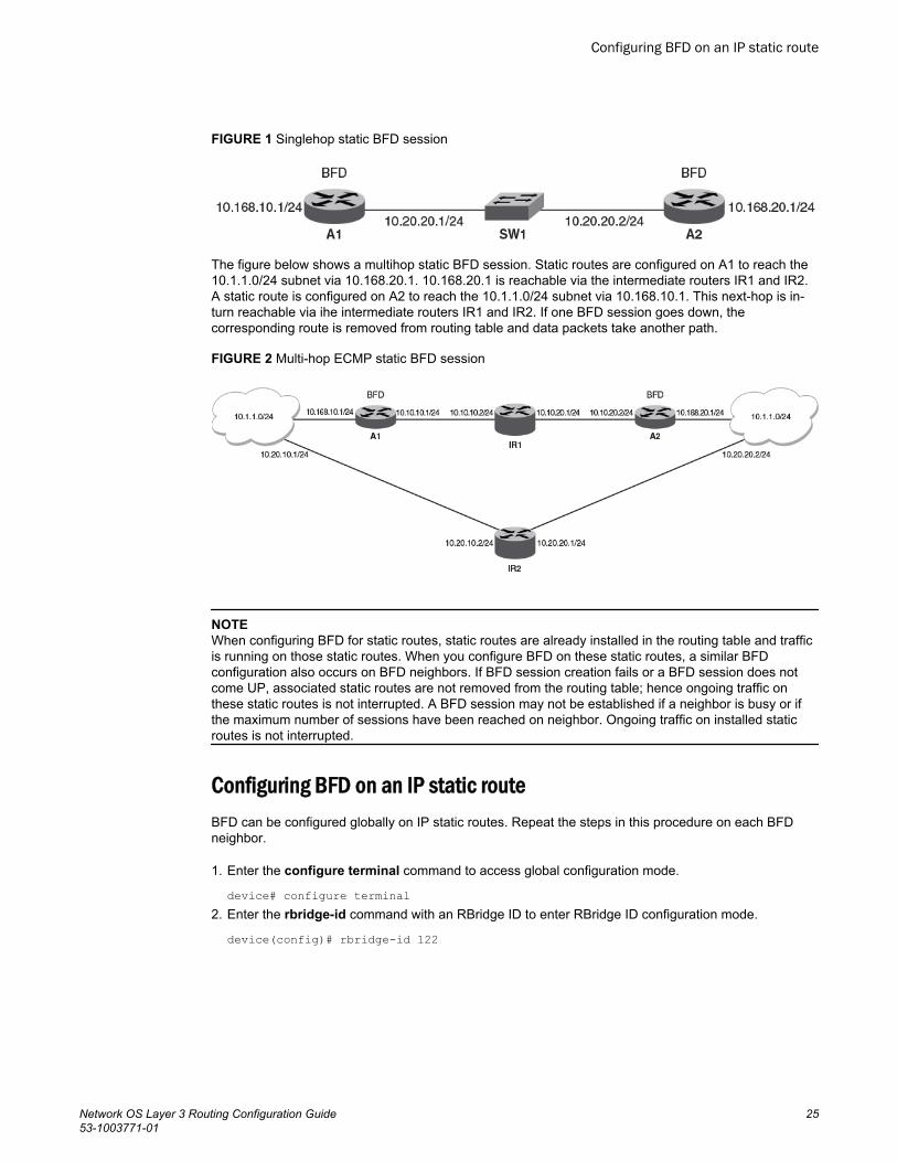
FIGURE 1 Singlehop static BFD session
The figure below shows a multihop static BFD session. Static routes are configured on A1 to reach the10.1.1.0/24 subnet via 10.168.20.1. 10.168.20.1 is reachable via the intermediate routers IR1 and IR2.A static route is configured on A2 to reach the 10.1.1.0/24 subnet via 10.168.10.1. This next-hop is in-turn reachable via ihe intermediate routers IR1 and IR2. If one BFD session goes down, thecorresponding route is removed from routing table and data packets take another path.
FIGURE 2 Multi-hop ECMP static BFD session
NOTEWhen configuring BFD for static routes, static routes are already installed in the routing table and trafficis running on those static routes. When you configure BFD on these static routes, a similar BFDconfiguration also occurs on BFD neighbors. If BFD session creation fails or a BFD session does notcome UP, associated static routes are not removed from the routing table; hence ongoing traffic onthese static routes is not interrupted. A BFD session may not be established if a neighbor is busy or ifthe maximum number of sessions have been reached on neighbor. Ongoing traffic on installed staticroutes is not interrupted.
Configuring BFD on an IP static routeBFD can be configured globally on IP static routes. Repeat the steps in this procedure on each BFDneighbor.
1. Enter the configure terminal command to access global configuration mode.
device# configure terminal2. Enter the rbridge-id command with an RBridge ID to enter RBridge ID configuration mode.
device(config)# rbridge-id 122
Configuring BFD on an IP static route
Network OS Layer 3 Routing Configuration Guide 2553-1003771-01
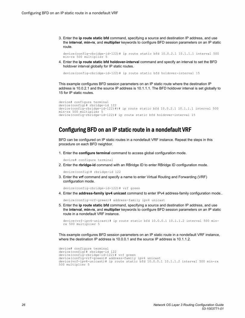
3. Enter the ip route static bfd command, specifying a source and destination IP address, and usethe interval, min-rx, and multiplier keywords to configure BFD session parameters on an IP staticroute.
device(config-rbridge-id-122)# ip route static bfd 10.0.2.1 10.1.1.1 interval 500 min-rx 500 multiplier 5
4. Enter the ip route static bfd holdover-interval command and specify an interval to set the BFDholdover interval globally for IP static routes.
device(config-rbridge-id-122)# ip route static bfd holdover-interval 15
This example configures BFD session parameters on an IP static route where the destination IPaddress is 10.0.2.1 and the source IP address is 10.1.1.1. The BFD holdover interval is set globally to15 for IP static routes.
device# configure terminaldevice(config)# rbridge-id 122device(config-rbridge-id-122)#)# ip route static bfd 10.0.2.1 10.1.1.1 interval 500 min-rx 500 multiplier 5 device(config-rbridge-id-122)# ip route static bfd holdover-interval 15
Configuring BFD on an IP static route in a nondefault VRFBFD can be configured on IP static routes in a nondefault VRF instance. Repeat the steps in thisprocedure on each BFD neighbor.
1. Enter the configure terminal command to access global configuration mode.
device# configure terminal2. Enter the rbridge-id command with an RBridge ID to enter RBridge ID configuration mode.
device(config)# rbridge-id 1223. Enter the vrf command and specify a name to enter Virtual Routing and Forwarding (VRF)
configuration mode.
device(config-rbridge-id-122)# vrf green4. Enter the address-family ipv4 unicast command to enter IPv4 address-family configuration mode..
device(config-vrf-green)# address-family ipv4 unicast5. Enter the ip route static bfd command, specifying a source and destination IP address, and use
the interval, min-rx, and multiplier keywords to configure BFD session parameters on an IP staticroute in a nondefault VRF instance.
device(vrf-ipv4-unicast)# ip route static bfd 10.0.0.1 10.1.1.2 interval 500 min-rx 500 multiplier 5
This example configures BFD session parameters on an IP static route in a nondefault VRF instance,where the destination IP address is 10.0.0.1 and the source IP address is 10.1.1.2.
device# configure terminaldevice(config)# rbridge-id 122device(config-rbridge-id-122)# vrf greendevice(config-vrf-green)# address-family ipv4 unicastdevice(vrf-ipv4-unicast)# ip route static bfd 10.0.0.1 10.1.1.2 interval 500 min-rx 500 multiplier 5
Configuring BFD on an IP static route in a nondefault VRF
26 Network OS Layer 3 Routing Configuration Guide53-1003771-01
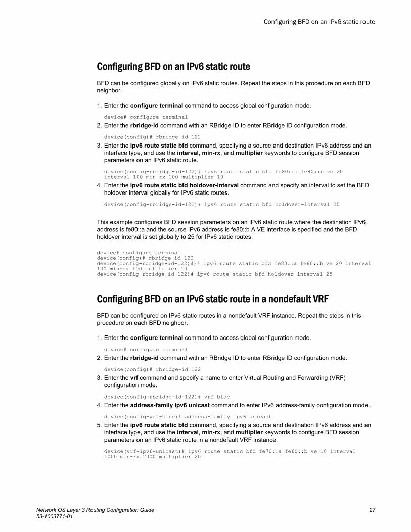
Configuring BFD on an IPv6 static routeBFD can be configured globally on IPv6 static routes. Repeat the steps in this procedure on each BFDneighbor.
1. Enter the configure terminal command to access global configuration mode.
device# configure terminal2. Enter the rbridge-id command with an RBridge ID to enter RBridge ID configuration mode.
device(config)# rbridge-id 1223. Enter the ipv6 route static bfd command, specifying a source and destination IPv6 address and an
interface type, and use the interval, min-rx, and multiplier keywords to configure BFD sessionparameters on an IPv6 static route.
device(config-rbridge-id-122)# ipv6 route static bfd fe80::a fe80::b ve 20 interval 100 min-rx 100 multiplier 10
4. Enter the ipv6 route static bfd holdover-interval command and specify an interval to set the BFDholdover interval globally for IPv6 static routes.
device(config-rbridge-id-122)# ipv6 route static bfd holdover-interval 25
This example configures BFD session parameters on an IPv6 static route where the destination IPv6address is fe80::a and the source IPv6 address is fe80::b A VE interface is specified and the BFDholdover interval is set globally to 25 for IPv6 static routes.
device# configure terminaldevice(config)# rbridge-id 122device(config-rbridge-id-122)#)# ipv6 route static bfd fe80::a fe80::b ve 20 interval 100 min-rx 100 multiplier 10device(config-rbridge-id-122)# ipv6 route static bfd holdover-interval 25
Configuring BFD on an IPv6 static route in a nondefault VRFBFD can be configured on IPv6 static routes in a nondefault VRF instance. Repeat the steps in thisprocedure on each BFD neighbor.
1. Enter the configure terminal command to access global configuration mode.
device# configure terminal2. Enter the rbridge-id command with an RBridge ID to enter RBridge ID configuration mode.
device(config)# rbridge-id 1223. Enter the vrf command and specify a name to enter Virtual Routing and Forwarding (VRF)
configuration mode.
device(config-rbridge-id-122)# vrf blue4. Enter the address-family ipv6 unicast command to enter IPv6 address-family configuration mode..
device(config-vrf-blue)# address-family ipv6 unicast5. Enter the ipv6 route static bfd command, specifying a source and destination IPv6 address and an
interface type, and use the interval, min-rx, and multiplier keywords to configure BFD sessionparameters on an IPv6 static route in a nondefault VRF instance.
device(vrf-ipv6-unicast)# ipv6 route static bfd fe70::a fe60::b ve 10 interval 1000 min-rx 2000 multiplier 20
Configuring BFD on an IPv6 static route
Network OS Layer 3 Routing Configuration Guide 2753-1003771-01
This example configures BFD session parameters on an IPv6 static route in a nondefault VRFinstance, where the destination IPv6 address is fe80::a and the source IPv6 address is fe80::b. A VEinterface is specified.
device# configure terminaldevice(config)# rbridge-id 122device(config-rbridge-id-122)# vrf bluedevice(config-vrf-blue)# address-family ipv6 unicastdevice(vrf-ipv6-unicast)# ipv6 route static bfd fe70::a fe60::b ve 10 interval 1000 min-rx 2000 multiplier 20
IP Route Management
28 Network OS Layer 3 Routing Configuration Guide53-1003771-01
PBR
● Policy-Based Routing......................................................................................................29● Policy-Based Routing behavior....................................................................................... 30● Policy-Based Routing with differing next hops................................................................ 31● Policy-Based Routing uses of NULL0............................................................................. 32
Policy-Based RoutingPolicy-Based Routing (PBR) allows you to use ACLs and route maps to selectively modify and route IPpackets in hardware.
Basically, the ACLs classify the traffic and route maps that match on the ACLs set routing attributes forthe traffic. A PBR policy specifies the next hop for traffic that matches the policy, as follows:
• For standard ACLs with PBR, you can route IP packets based on their source IP address.• For extended ACLs with PBR, you can route IP packets based on all of the matching criteria in the
extended ACL.
NOTEFor details about ACLs, refer to the "Managing and Configuring ACLs" section of the Network OSSecurity Configuration Guide.
To configure PBR, you define the policies using IP ACLs and route maps, then enable PBR onindividual interfaces. The platform programs the ACLs on the interfaces, and routes traffic that matchesthe ACLs according to the instructions provided by the “set” statements in the route map entry.
Currently, the following platforms support PBR:
• Brocade VDX 8770• Brocade VDX 6740• Brocade VDX 6740T• Brocade VDX 6740T-1G
You can configure the Brocade device to perform the following types of PBR based on a packet’s Layer3 and Layer 4 information:
• Select the next-hop gateway.• Set the DSCP value.• Send the packet to the null interface (null0) to drop the packets.
Using PBR, you can define a set of classifications that, when met, cause a packet to be forwarded to apredetermined next-hop interface, bypassing the path determined by normal routing. You can definemultiple match and next-hop specifications on the same interface. The configuration of a set of matchcriteria and corresponding routing information (for example next hops and DSCP values) is referred toas a stanza.
You can create multiple stanzas within a route-map configuration and assign the stanza an“Instance_ID” that controls the program positioning within the route map. Furthermore, when the routemap is created, you specify a deny or permit construct for the stanza. In addition, the ACL used for the“match” criteria also contains a deny or permit construct.
Network OS Layer 3 Routing Configuration Guide 2953-1003771-01
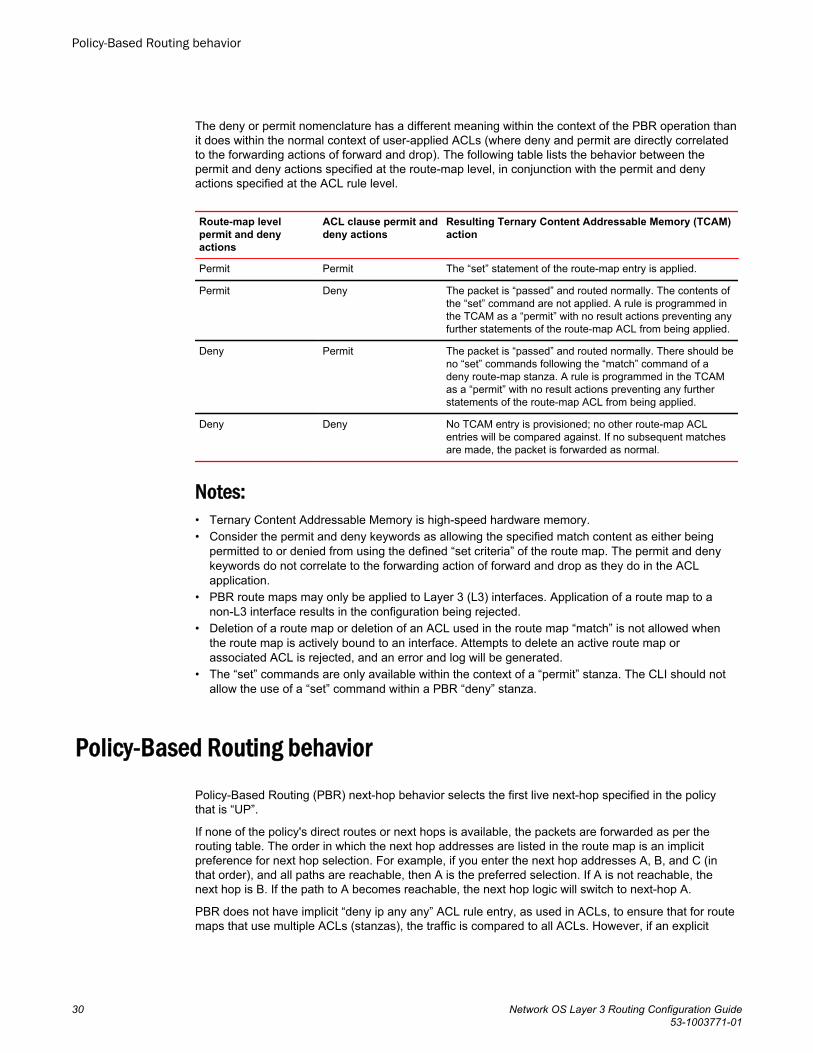
The deny or permit nomenclature has a different meaning within the context of the PBR operation thanit does within the normal context of user-applied ACLs (where deny and permit are directly correlatedto the forwarding actions of forward and drop). The following table lists the behavior between thepermit and deny actions specified at the route-map level, in conjunction with the permit and denyactions specified at the ACL rule level.
Route-map levelpermit and denyactions
ACL clause permit anddeny actions
Resulting Ternary Content Addressable Memory (TCAM)action
Permit Permit The “set” statement of the route-map entry is applied.
Permit Deny The packet is “passed” and routed normally. The contents ofthe “set” command are not applied. A rule is programmed inthe TCAM as a “permit” with no result actions preventing anyfurther statements of the route-map ACL from being applied.
Deny Permit The packet is “passed” and routed normally. There should beno “set” commands following the “match” command of adeny route-map stanza. A rule is programmed in the TCAMas a “permit” with no result actions preventing any furtherstatements of the route-map ACL from being applied.
Deny Deny No TCAM entry is provisioned; no other route-map ACLentries will be compared against. If no subsequent matchesare made, the packet is forwarded as normal.
Notes:• Ternary Content Addressable Memory is high-speed hardware memory.• Consider the permit and deny keywords as allowing the specified match content as either being
permitted to or denied from using the defined “set criteria” of the route map. The permit and denykeywords do not correlate to the forwarding action of forward and drop as they do in the ACLapplication.
• PBR route maps may only be applied to Layer 3 (L3) interfaces. Application of a route map to anon-L3 interface results in the configuration being rejected.
• Deletion of a route map or deletion of an ACL used in the route map “match” is not allowed whenthe route map is actively bound to an interface. Attempts to delete an active route map orassociated ACL is rejected, and an error and log will be generated.
• The “set” commands are only available within the context of a “permit” stanza. The CLI should notallow the use of a “set” command within a PBR “deny” stanza.
Policy-Based Routing behaviorPolicy-Based Routing (PBR) next-hop behavior selects the first live next-hop specified in the policythat is “UP”.
If none of the policy's direct routes or next hops is available, the packets are forwarded as per therouting table. The order in which the next hop addresses are listed in the route map is an implicitpreference for next hop selection. For example, if you enter the next hop addresses A, B, and C (inthat order), and all paths are reachable, then A is the preferred selection. If A is not reachable, thenext hop is B. If the path to A becomes reachable, the next hop logic will switch to next-hop A.
PBR does not have implicit “deny ip any any” ACL rule entry, as used in ACLs, to ensure that for routemaps that use multiple ACLs (stanzas), the traffic is compared to all ACLs. However, if an explicit
Policy-Based Routing behavior
30 Network OS Layer 3 Routing Configuration Guide53-1003771-01
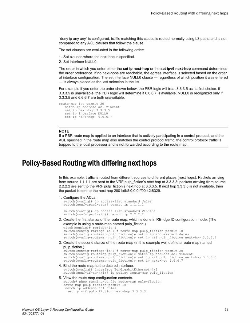
“deny ip any any” is configured, traffic matching this clause is routed normally using L3 paths and is notcompared to any ACL clauses that follow the clause.
The set clauses are evaluated in the following order:
1. Set clauses where the next hop is specified.2. Set interface NULL0.
The order in which you enter either the set ip next-hop or the set ipv6 next-hop command determinesthe order preference. If no next-hops are reachable, the egress interface is selected based on the orderof interface configuration. The set interface NULL0 clause — regardless of which position it was entered— is always placed as the last selection in the list.
For example if you enter the order shown below, the PBR logic will treat 3.3.3.5 as its first choice. If3.3.3.5 is unavailable, the PBR logic will determine if 6.6.6.7 is available. NULL0 is recognized only if3.3.3.5 and 6.6.6.7 are both unavailable.route-map foo permit 20 match ip address acl Vincent set ip next-hop 3.3.3.5 set ip interface NULL0 set ip next-hop 6.6.6.7
NOTEIf a PBR route map is applied to an interface that is actively participating in a control protocol, and theACL specified in the route map also matches the control protocol traffic, the control protocol traffic istrapped to the local processor and is not forwarded according to the route map.
Policy-Based Routing with differing next hopsIn this example, traffic is routed from different sources to different places (next hops). Packets arrivingfrom source 1.1.1.1 are sent to the VRF pulp_fiction’s next hop at 3.3.3.3; packets arriving from source2.2.2.2 are sent to the VRF pulp_fiction’s next hop at 3.3.3.5. If next hop 3.3.3.5 is not available, thenthe packet is sent to the next hop 2001:db8:0:0:0:ff00:42:8329.
1. Configure the ACLs.switch(config)# ip access-list standard Julesswitch(conf-ipacl-std)# permit ip 1.1.1.1switch(config)# ip access-list standard Vincentswitch(conf-ipacl-std)# permit ip 2.2.2.2
2. Create the first stanza of the route map, which is done in RBridge ID configuration mode. (Theexample is using a route-map named pulp_fiction.)witch(config)# rbridge-id 1switch(config-rbridge-id-1)# route-map pulp_fiction permit 10switch(config-routemap pulp_fiction)# match ip address acl Julesswitch(config-routemap pulp_fiction)# set ip vrf pulp_fiction next-hop 3.3.3.3
3. Create the second stanza of the route-map (in this example well define a route-map namedpulp_fiction.)switch(config-rbridge-id-1)# route-map pulp_fiction permit 20switch(config-routemap pulp_fiction)# match ip address acl Vincentswitch(config-routemap pulp_fiction)# set ip vrf pulp_fiction next-hop 3.3.3.5switch(config-routemap pulp_fiction)# set ip next-hop 6.6.6.7
4. Bind the route map to the desired interface.switch(config)# interface TenGigabitEthernet 4/1switch(conf-if-te-4/1)# ip policy route-map pulp_fiction
5. View the route map configuration contents.switch# show running-config route-map pulp-fictionroute-map pulp-fiction permit 10 match ip address acl Jules set ip vrf pulp_fiction next-hop 3.3.3.3
Policy-Based Routing with differing next hops
Network OS Layer 3 Routing Configuration Guide 3153-1003771-01
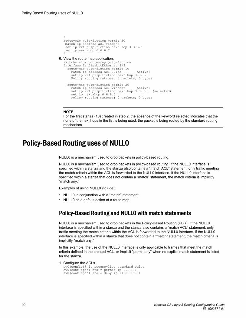
!route-map pulp-fiction permit 20 match ip address acl Vincent set ip vrf pulp_fiction next-hop 3.3.3.5 set ip next-hop 6.6.6.7!
6. View the route map application.switch# show route-map pulp-fictionInterface TenGigabitEthernet 3/3 route-map pulp-fiction permit 10 match ip address acl Jules (Active) set ip vrf pulp_fiction next-hop 3.3.3.3 Policy routing matches: 0 packets; 0 bytes route-map pulp-fiction permit 20 match ip address acl Vincent (Active) set ip vrf pulp_fiction next-hop 3.3.3.5 (selected) set ip next-hop 6.6.6.7 Policy routing matches: 0 packets; 0 bytes
NOTEFor the first stanza (10) created in step 2, the absence of the keyword selected indicates that thenone of the next hops in the list is being used; the packet is being routed by the standard routingmechanism.
Policy-Based Routing uses of NULL0NULL0 is a mechanism used to drop packets in policy-based routing.
NULL0 is a mechanism used to drop packets in policy-based routing. If the NULL0 interface isspecified within a stanza and the stanza also contains a “match ACL” statement, only traffic meetingthe match criteria within the ACL is forwarded to the NULL0 interface. If the NULL0 interface isspecified within a stanza that does not contain a “match” statement, the match criteria is implicitly“match any.”
Examples of using NULL0 include:
• NULL0 in conjunction with a “match” statement.• NULL0 as a default action of a route map.
Policy-Based Routing and NULL0 with match statementsNULL0 is a mechanism used to drop packets in the Policy-Based Routing (PBR). If the NULL0interface is specified within a stanza and the stanza also contains a “match ACL” statement, onlytraffic meeting the match criteria within the ACL is forwarded to the NULL0 interface. If the NULL0interface is specified within a stanza that does not contain a “match” statement, the match criteria isimplicitly “match any.”
In this example, the use of the NULL0 interface is only applicable to frames that meet the matchcriteria defined in the created ACL, or implicit "permit any" when no explicit match statement is listedfor the stanza.
1. Configure the ACLs.sw0(config)# ip access-list standard Julessw0(conf-ipacl-std)# permit ip 1.1.1.1sw0(conf-ipacl-std)# deny ip 11.11.11.11
Policy-Based Routing uses of NULL0
32 Network OS Layer 3 Routing Configuration Guide53-1003771-01

sw0(config)# ip access-list standard Vincentsw0(conf-ipacl-std)# permit ip 2.2.2.2
2. Create the first stanza of the route map, which is done in RBridge ID configuration mode. (Theexample is using a route-map named pulp_fiction.)sw0(config)# rbridge-id 1sw0(config-rbridge-id-1)# route-map pulp_fiction permit 10sw0(config-routemap pulp_fiction)# match ip address acl Julessw0(config-routemap pulp_fiction)# set ip vrf pulp_fiction next-hop 3.3.3.3sw0(config-routemap pulp_fiction)# set ip interface NULL0
3. Create the second stanza of the route map. (The example is using a route map named pulp_fiction.)sw0(config-rbridge-id-1)# route-map pulp_fiction permit 20sw0(config-routemap pulp_fiction)# match ip address acl Vincentsw0(config-routemap pulp_fiction)# set ip vrf pulp_fiction next-hop 3.3.3.5sw0(config-routemap pulp_fiction)# set ipv6 next-hop 2001:db8:0:0:0:ff00:42:8329Based on the above configuration, when address 1.1.1.1 is received, it matches stanza 10:
• If the next hop 3.3.3.3 is selected, the packet is forwarded to 3.3.3.3.• If 3.3.3.3 is not selected by the PBR logic, the packet is sent to the next specified next-hop, which
is the NULL0 interface, resulting in the traffic being dropped.• If address 11.11.11.11 is received, since it matches the deny case of the ACL, it is denied from
using the next hops specified in the route map and is forwarded according to the standard logic.• If address 12.12.12.12 is received, because it meets none of the specified match criteria in either
of the two stanzas, it basically falls off the end of the route map and reverts to using the standardrouting logic.
Policy-Based Routing and NULL0 as route map default actionThis example shows the use of the NULL0 interface.
In this example, the use of the NULL0 interface is only applicable to frames that meet the match criteriadefined in the created ACL.
1. Configure the ACLs.sw0(config)# ip access-list standard Julessw0(conf-ipacl-std)# permit ip 1.1.1.1sw0(conf-ipacl-std)# deny ip 11.11.11.11sw0(config)# ip access-list standard Vincentsw0(conf-ipacl-std)# permit ip 2.2.2.2
2. Create the first stanza of the route map, which s done in RBridge ID configuration mode. (Theexample is using a route-map named pulp_fiction.)sw0(config)# rbridge-id 1sw0(config-rbridge-id-1)# route-map pulp_fiction permit 10sw0(config-routemap pulp_fiction)# match ip address acl Julessw0(config-routemap pulp_fiction)# set ip vrf pulp_fiction next-hop 3.3.3.3sw0(config-routemap pulp_fiction)# set ip interface NULL0
3. Create the second stanza of the route map. (The example is using a route-map named pulp_fiction.)sw0(config-rbridge-id-1)# route-map pulp_fiction permit 20sw0(config-routemap pulp_fiction)# match ip address acl Vincentsw0(config-routemap pulp_fiction)# set ip vrf pulp_fiction next-hop 3.3.3.5
4. Create the third stanza, which provides the default action of the route map.sw0(config-rbridge-id-1)# route-map pulp_fiction permit 30sw0(config-routemap pulp_fiction)# set ip interface NULL0The above configuration introduces a third stanza that defines the routing desired for all frames thatdo not meet any of the match criteria defined by the route map.
Based on the above configuration, when address 1.1.1.1 is received, it matches stanza 10:
• If the next hop 3.3.3.3 is selected, the packet is forwarded to 3.3.3.3.• If 3.3.3.3 is not selected by the PBR logic, the packet is sent to the next specified next-hop, which
is the NULL0 interface, resulting in the traffic being dropped.
Policy-Based Routing and NULL0 as route map default action
Network OS Layer 3 Routing Configuration Guide 3353-1003771-01
• If address 11.11.11.11 is received, since it matches the deny case of the ACL, it is denied fromusing the next hops specified in the route map and will be forwarded according to the standardlogic.
• If address 12.12.12.12 is received, because it meets none of the specified match criteria in eitherof the first two stanzas, it reaches the third stanza. Since a no “match” statement is specified, it isan implicit “match any.” The address 12.12.12.12 is forwarded to the NULL0 interface where it isdropped.
Providing the default stanza enables a mechanism whereby if any packet is received that does notmeet the match criteria set by the route map, the traffic is dropped.
PBR
34 Network OS Layer 3 Routing Configuration Guide53-1003771-01
PIM
● Protocol-independent multicast (PIM) overview..............................................................35● PIM-sparse overview ......................................................................................................36● Configuring PIM-sparse.................................................................................................. 40
Protocol-independent multicast (PIM) overviewThe protocol-independent multicast (PIM) protocol is a family of IP multicast protocols. PIM does notrely on any particular routing protocol for creating its network topology state. Instead, PIM uses routinginformation supplied by other traditional routing protocols such as Open Shortest Path First, BorderGateway Protocol, and Multicast Source Discovery Protocol.
PIM messages are sent encapsulated in an IP packet with the IP protocol field set to 103. Depending onthe type of message, the packet is either sent to the PIM All-Router-Multicast address (224.0.0.13) orsent as unicast to a specific host.
As with IP multicast, the main use case of PIM is for the source to be able to send the same informationto multiple receivers by using a single stream of traffic. This helps minimize the processing load on thesource as it needs to maintain only one session irrespective of the number of actual receivers. It alsominimizes the load on the IP network since the packets are sent only on links that lead to an interestedreceiver.
Several types of PIM exist, but in this release Brocade supports only PIM sparse mode (PIM-sparse,PIM-SM). PIM-sparse explicitly builds unidirectional shared trees rooted at a rendezvous point (RP) pergroup, and optionally creates shortest-path trees per source. PIM-sparse can be used in VCS modeonly.
PIM prerequisitesPIM requires the following to function properly:
• A timer mechanism• An inter-process communication (IPC) mechanism• An accessible routing information base (RIB), for obtaining routing information• Support for receiving and transmitting both unicast and multicast packets• An Internet group-management profile (IGMP) module, for correct operation designated routers
(DRs) under PIM
PIM considerations and limitationsThis release of Network OS includes the following PIM support:
• 8 rendevous point (RP) devices• 32 virtual interfaces. The virtual interfaces can be either Layer 3 VLAN or router ports• 32 output interfaces• 4,000 Layer 3 multicast group IDs• 2,000 (S,G) forwarding entries
Network OS Layer 3 Routing Configuration Guide 3553-1003771-01
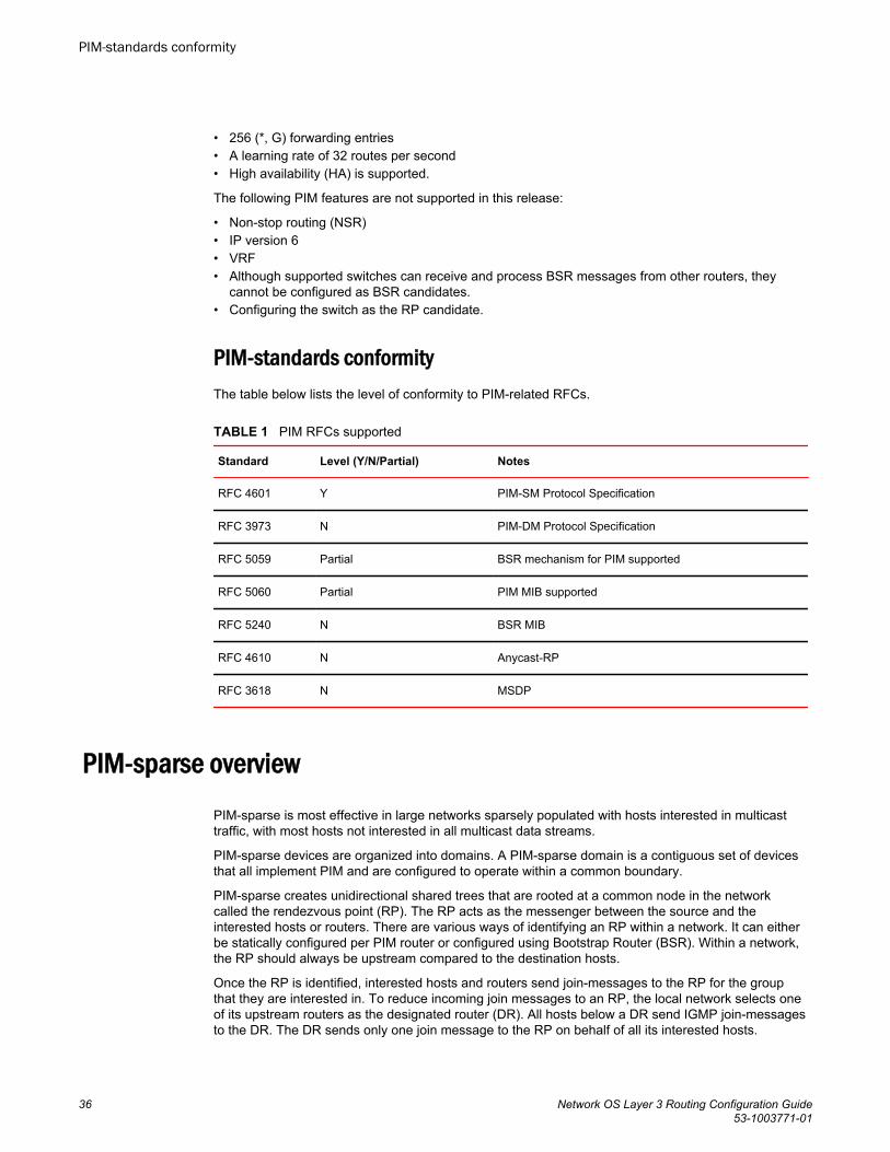
• 256 (*, G) forwarding entries• A learning rate of 32 routes per second• High availability (HA) is supported.
The following PIM features are not supported in this release:
• Non-stop routing (NSR)• IP version 6• VRF• Although supported switches can receive and process BSR messages from other routers, they
cannot be configured as BSR candidates.• Configuring the switch as the RP candidate.
PIM-standards conformityThe table below lists the level of conformity to PIM-related RFCs.
PIM RFCs supported TABLE 1
Standard Level (Y/N/Partial) Notes
RFC 4601 Y PIM-SM Protocol Specification
RFC 3973 N PIM-DM Protocol Specification
RFC 5059 Partial BSR mechanism for PIM supported
RFC 5060 Partial PIM MIB supported
RFC 5240 N BSR MIB
RFC 4610 N Anycast-RP
RFC 3618 N MSDP
PIM-sparse overviewPIM-sparse is most effective in large networks sparsely populated with hosts interested in multicasttraffic, with most hosts not interested in all multicast data streams.
PIM-sparse devices are organized into domains. A PIM-sparse domain is a contiguous set of devicesthat all implement PIM and are configured to operate within a common boundary.
PIM-sparse creates unidirectional shared trees that are rooted at a common node in the networkcalled the rendezvous point (RP). The RP acts as the messenger between the source and theinterested hosts or routers. There are various ways of identifying an RP within a network. It can eitherbe statically configured per PIM router or configured using Bootstrap Router (BSR). Within a network,the RP should always be upstream compared to the destination hosts.
Once the RP is identified, interested hosts and routers send join-messages to the RP for the groupthat they are interested in. To reduce incoming join messages to an RP, the local network selects oneof its upstream routers as the designated router (DR). All hosts below a DR send IGMP join-messagesto the DR. The DR sends only one join message to the RP on behalf of all its interested hosts.
PIM-standards conformity
36 Network OS Layer 3 Routing Configuration Guide53-1003771-01

PIM-sparse also provides the option of creating a source-based tree rooted at a router adjacent to thetree. This provides the destination hosts with an option of switching from the shared tree to the source-based tree if this is a shorter path between the source and the destination.
PIM-sparse device typesDevices configured with PIM-sparse interfaces also can be configured to fill one or more of the followingroles:
• PIM multicast border router (PMBR) — A PIM device that has interfaces within the PIM domain andother interfaces outside the PIM domain. PBMRs connect the PIM domain to the Internet.
• Bootstrap router (BSR) — A router that distributes rendezvous point (RP) information to the otherPIM-sparse devices within the domain. Each PIM-sparse domain has one active BSR. Forredundancy, you can configure ports on multiple devices as candidate BSRs. The PIM-sparseprotocol uses an election process to select one of the candidate BSRs as the BSR for the domain.The BSR with the highest BSR priority (a user-configurable parameter) is elected. If the prioritiesresult in a tie, then the candidate BSR interface with the highest IP address is elected.
The BSR must be configured as part of the L3 core network.• Rendezvous point (RP) — The meeting point for PIM-sparse sources and receivers. A PIM-sparse
domain can have multiple RPs, but each PIM-sparse multicast group address can have only oneactive RP. PIM-sparse devices learn the addresses of RPs and the groups for which they areresponsible from messages that the BSR sends to each of the PIM-sparse devices.
The RP must be configured as part of the L3 core network.
NOTEBrocade recommends that you configure the same ports as candidate BSRs and RPs.
• PIM designated router (DR) — Once the RP has been identified, each interested host/router sendsjoin-messages to the RP for the group that they are interested in. The local network selects one of itsupstream routers as the designated router (DR). All hosts below a DR send IGMP join-messages tothe DR. The DR in turn sends only one join message to the RP on behalf of all its interested hosts.The RP receives the first few packets of the multicast stream, encapsulated in the PIM registermessage, from the source hosts. These messages are sent as a unicast to the RP. The RP de-encapsulates these packets and forwards them to the respective DRs.
NOTEDR election is based first on the router with the highest configured DR priority for an interface (if DRpriority has been configured), and based next on the router with the highest IP address. To configureDR priority, use the ip pim dr-priority command. For more information about this command, refer toNetwork OS Command Reference.
PIM-sparse topologiesThis section shows diagrams of two supported PIM topologies.
The figure below shows the components for a single-tier VCS PIM topology.
PIM-sparse device types
Network OS Layer 3 Routing Configuration Guide 3753-1003771-01
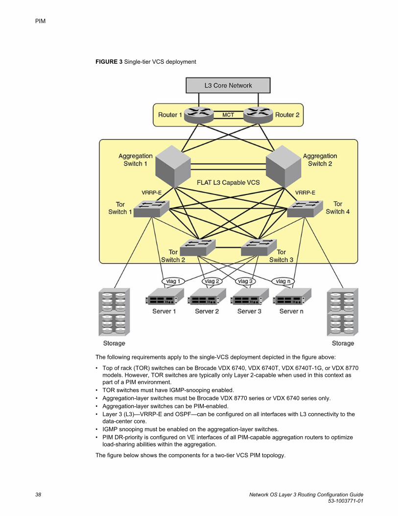
FIGURE 3 Single-tier VCS deployment
The following requirements apply to the single-VCS deployment depicted in the figure above:
• Top of rack (TOR) switches can be Brocade VDX 6740, VDX 6740T, VDX 6740T-1G, or VDX 8770models. However, TOR switches are typically only Layer 2-capable when used in this context aspart of a PIM environment.
• TOR switches must have IGMP-snooping enabled.• Aggregation-layer switches must be Brocade VDX 8770 series or VDX 6740 series only.• Aggregation-layer switches can be PIM-enabled.• Layer 3 (L3)—VRRP-E and OSPF—can be configured on all interfaces with L3 connectivity to the
data-center core.• IGMP snooping must be enabled on the aggregation-layer switches.• PIM DR-priority is configured on VE interfaces of all PIM-capable aggregation routers to optimize
load-sharing abilities within the aggregation.
The figure below shows the components for a two-tier VCS PIM topology.
PIM
38 Network OS Layer 3 Routing Configuration Guide53-1003771-01
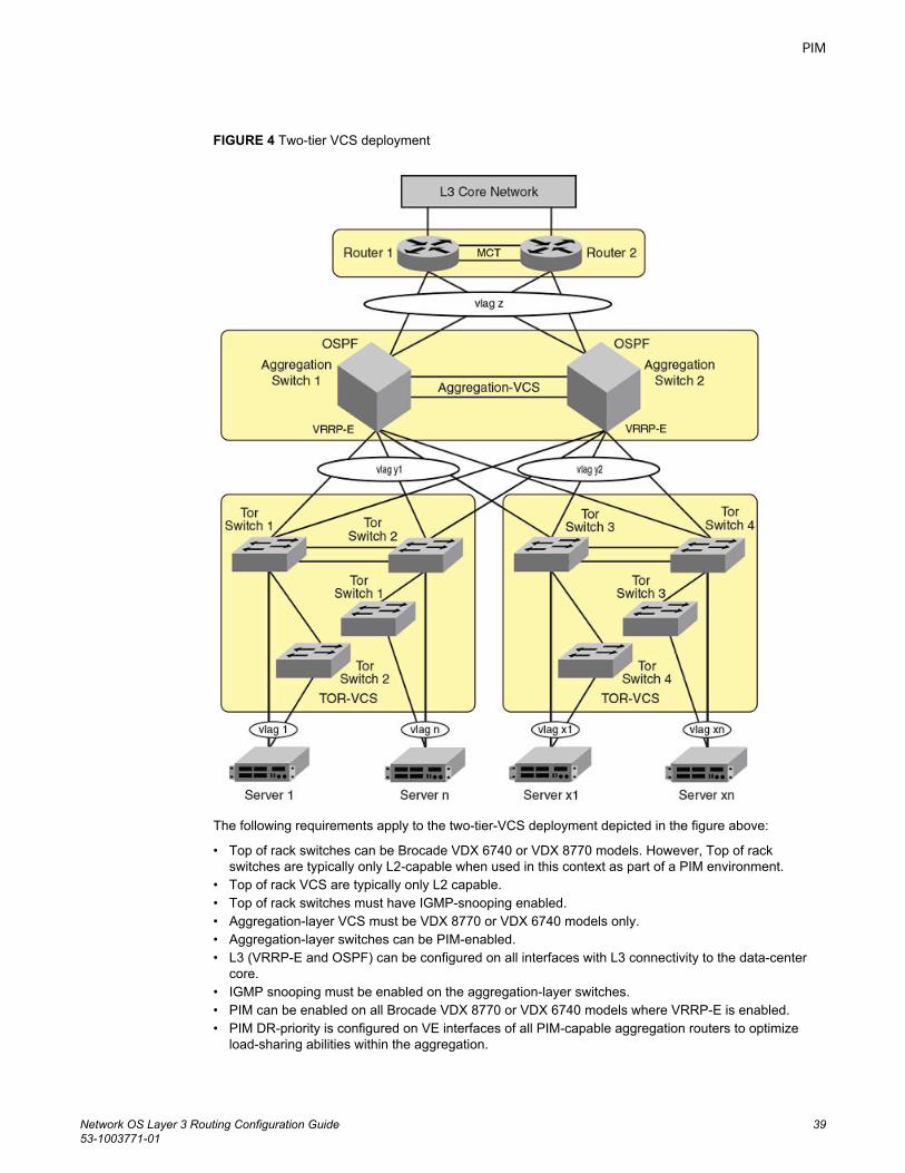
FIGURE 4 Two-tier VCS deployment
The following requirements apply to the two-tier-VCS deployment depicted in the figure above:
• Top of rack switches can be Brocade VDX 6740 or VDX 8770 models. However, Top of rackswitches are typically only L2-capable when used in this context as part of a PIM environment.
• Top of rack VCS are typically only L2 capable.• Top of rack switches must have IGMP-snooping enabled.• Aggregation-layer VCS must be VDX 8770 or VDX 6740 models only.• Aggregation-layer switches can be PIM-enabled.• L3 (VRRP-E and OSPF) can be configured on all interfaces with L3 connectivity to the data-center
core.• IGMP snooping must be enabled on the aggregation-layer switches.• PIM can be enabled on all Brocade VDX 8770 or VDX 6740 models where VRRP-E is enabled.• PIM DR-priority is configured on VE interfaces of all PIM-capable aggregation routers to optimize
load-sharing abilities within the aggregation.
PIM
Network OS Layer 3 Routing Configuration Guide 3953-1003771-01
Configuring PIM-sparseUse the procedures in this section for PIM-sparse configuration of a single-tier VCS.
PIM-sparse configuration notesBe aware of the following issues when configuring PIM-sparse:
• VLAGs must belong to PIM-enabled VLANs. For more information, refer to the “Configuring LinkAggregation” chapter of the Network OS Layer 2 Switching Configuration Guide.
• Set up your VLAGs before performing any PIM-specific configuration.• Make sure that the rendezvous point (RP) is configured. This functionality should be provided by
another router that is outside of the VCS Fabric.
NOTERP functionality, either static or dynamic, is not supported inside the VCS Fabric.
• All PIM-enabled aggregation layer devices should have a direct Layer 3 connection to RP.• Make sure that the bootstrap router (BSR), if applicable to your setup, is configured. The BSR can
be any third-party box that supports PIM, BSR, and rendezvous point (RP) functionality. If you areusing a Brocade MLX switch as the bootstrap router, refer to the Brocade MLX Series and NetIronFamily Configuration Guide for more information.
Graphic guide to PIM-sparse configurationThis diagram represents a sample PIM deployment on a single-tier VCS.
Refer to this diagram when performing the following procedures:
• Enabling IGMP snooping on access-layer switches on page 42• Enabling PIM on aggregation-layer switches on page 42
Configuring PIM-sparse
40 Network OS Layer 3 Routing Configuration Guide53-1003771-01
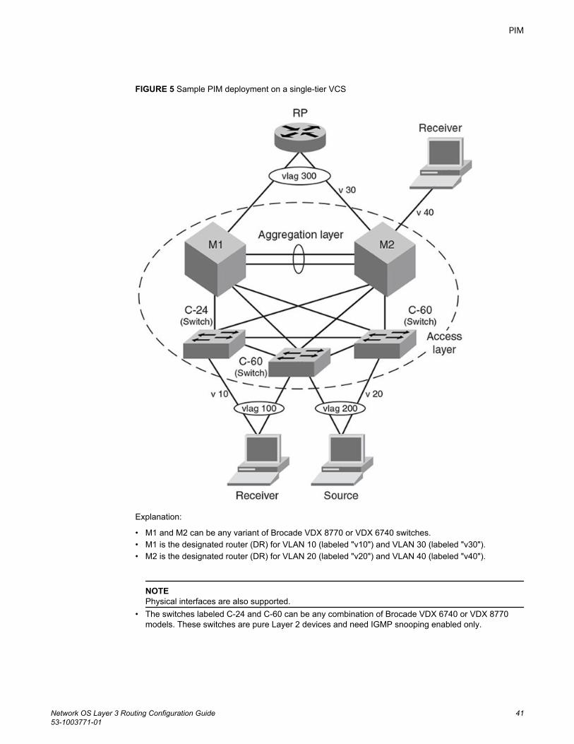
FIGURE 5 Sample PIM deployment on a single-tier VCS
Explanation:
• M1 and M2 can be any variant of Brocade VDX 8770 or VDX 6740 switches.• M1 is the designated router (DR) for VLAN 10 (labeled "v10") and VLAN 30 (labeled "v30").• M2 is the designated router (DR) for VLAN 20 (labeled "v20") and VLAN 40 (labeled "v40").
NOTEPhysical interfaces are also supported.
• The switches labeled C-24 and C-60 can be any combination of Brocade VDX 6740 or VDX 8770models. These switches are pure Layer 2 devices and need IGMP snooping enabled only.
PIM
Network OS Layer 3 Routing Configuration Guide 4153-1003771-01
Enabling IGMP snooping on access-layer switchesTowards PIM implementation on a VCS, use this procedure to enable IGMP snooping on every VLANof every access-layer RBridge.
NOTEIf IGMP snooping is enabled globally, you do not need to perform this procedure.
1. From the switch console, in privileged EXEC mode, enter global configuration mode.switch# configure terminal
2. Enter VLAN interface configuration mode for the first VLAN.switch(config)# int vlan 10
3. Enable IGMP snooping.switch(config-Vlan-10)# ip igmp snooping enable
4. Exit interface configuration mode.switch(config-Vlan-10)# exit
5. Enter VLAN interface configuration mode for the second VLAN.switch(config)# int vlan 20
6. Enable IGMP snooping.switch(config-Vlan-20)# ip igmp snooping enable
7. Exit interface configuration mode.switch(config-Vlan-20)# exit
8. Enter VLAN interface configuration mode for the third VLAN.switch(config)# int vlan 30
9. Enable IGMP snooping.switch(config-Vlan-30)# ip igmp snooping enable
10.Exit interface configuration mode.switch(config-Vlan-30)# exit
11.Enter VLAN interface configuration mode for the fourth VLAN.switch (config)# int vlan 40
12.Enable IGMP snooping.switch(config-Vlan-40)# ip igmp snooping enable
13.Enter the exit command to return to global configuration mode.switch(config-Vlan-40)# exitswitch(config)#
Enabling PIM on aggregation-layer switchesWhen implementing PIM-sparse on a VCS, after you enable IGMP snooping on the access layer,implement this procedure on every VLAN of every aggregation-layer RBridge.
1. In global configuration mode, enter VLAN interface configuration mode for the VLAN.switch(config)# int vlan 10
2. Enable IGMP snooping.switch(config-Vlan-10)# ip igmp snooping enable
3. Exit interface configuration mode.switch(config-Vlan-10)# exit
4. Enter RBridge ID configuration mode.switch(config)# rbridge-id 17
5. If a prefix list is required (for example for the rp-address, ip multicast-boundary, or ip pimneighbor-filter commands), create a prefix list.switch(config-rbridge-id-17)# ip prefix-list prefList1 deny 1.2.0.0/16 ge 17 le 30
6. Issue the router pim command to enable PIM for this switch.switch(config-rbridge-id-17)# router pim
7. To specify a static rendezvous point (RP):
Enabling IGMP snooping on access-layer switches
42 Network OS Layer 3 Routing Configuration Guide53-1003771-01
a) Enter the rp-address command, specifying the IP address of the RP router.switch(config-pim-router)# rp-address 10.22.22.22You can also specify a prefix list that defines a multicast group range.switch(config-pim-router)# rp-address 10.22.22.22 prefList1
b) Enter the exit command to return to RBridge-ID configuration mode.switch(config-pim-router)# exit
8. Enter interface subconfiguration mode for the VE interface associated with this VLAN.switch(config-rbridge-id-17)# int ve 10
9. Enter the no shut command to activate the VE interface and bring the ports online.switch(config-Ve-10)# no shut
10.Assign a unique IP address for the interface:switch(config-Ve-10)# ip addr 10.1.1.11/24
11.Enable PIM sparse mode for this interface.switch(config-Ve-10)# ip pim-sparse
12.To enable PIM neighbor-filter on this interface, enter the ip pim neighbor-filter command.switch(config-Ve-10)# ip pim neighbor-filter prefList1
13.To define this interface as a multicast boundary, enter the ip multicast-boundary command.switch(config-Ve-10)# ip multicast-boundary prefList2
14.Exit VE configuration mode.switch(config-Ve-10)# exitswitch(config-rbridge-id-17)#
Restricting unknown multicastThe restrict-unknown-multicast feature prevents the default flooding of multicast traffic on all ports of aVLAN.
The PIM topology and VLANs must be configured before activating this feature.
When this feature is enabled, (*,G,V) entries are programmed, and the non-PIM-DR does not processor create (*,*,V) routes and maintain them in the mrouter database. IP multicast data traffic is sent onlyto mrouter learned ports or PIM-hello learned ports.
1. Enter interface configuration mode for the VLAN whose unknown multicast traffic is to be restricted.switch(config)# interface vlan 100
2. Enter the ip igmp snooping restrict-unknown-multicast command.switch(config-Vlan-100)# ip igmp snooping restrict-unknown-multicast
Restricting unknown multicast
Network OS Layer 3 Routing Configuration Guide 4353-1003771-01

Restricting unknown multicast
44 Network OS Layer 3 Routing Configuration Guide53-1003771-01
OSPF
● OSPF overview............................................................................................................... 45● Configuring OSPF........................................................................................................... 54
OSPF overviewOpen Shortest Path First (OSPF) is a link-state routing protocol that uses link-state advertisements(LSAs) to update neighboring routers about a router’s interfaces. Each router maintains an identicalarea-topology database to determine the shortest path to any neighboring router.
OSPF is built upon a hierarchy of network components and areas. The highest level of the hierarchy isthe Autonomous System (AS). An autonomous system is defined as a number of networks, all of whichshare the same routing and administration characteristics. A backbone area forms the core of thenetwork, connecting all other areas. Details of these and other OSPF components are provided below.
Autonomous SystemAn AS can be divided into multiple areas as shown in the figure below. Each area represents acollection of contiguous networks and hosts (refer to OSPF areas on page 48). Areas limit the amountof advertisements sent (called flooding) within the network. An area is represented in OSPF by either anIP address or a number.
Network OS Layer 3 Routing Configuration Guide 4553-1003771-01
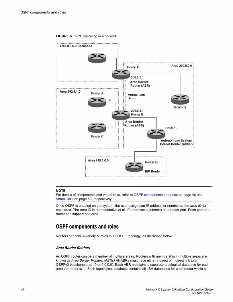
FIGURE 6 OSPF operating in a network
NOTEFor details of components and virtual links, refer to OSPF components and roles on page 46 and Virtual links on page 50, respectively.
Once OSPF is enabled on the system, the user assigns an IP address or number as the area ID foreach area. The area ID is representative of all IP addresses (subnets) on a router port. Each port on arouter can support one area.
OSPF components and rolesRouters can take a variety of roles in an OSPF topology, as discussed below.
Area Border Routers
An OSPF router can be a member of multiple areas. Routers with membership in multiple areas areknown as Area Border Routers (ABRs) All ABRs must have either a direct or indirect link to anOSPFv3 backbone area (0 or 0.0.0.0). Each ABR maintains a separate topological database for eacharea the router is in. Each topological database contains all LSA databases for each router within a
OSPF components and roles
46 Network OS Layer 3 Routing Configuration Guide53-1003771-01
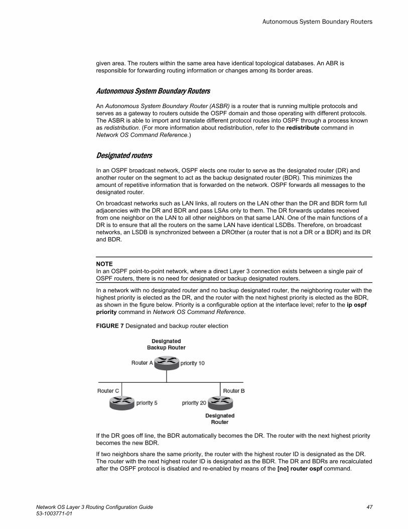
given area. The routers within the same area have identical topological databases. An ABR isresponsible for forwarding routing information or changes among its border areas.
Autonomous System Boundary Routers
An Autonomous System Boundary Router (ASBR) is a router that is running multiple protocols andserves as a gateway to routers outside the OSPF domain and those operating with different protocols.The ASBR is able to import and translate different protocol routes into OSPF through a process knownas redistribution. (For more information about redistribution, refer to the redistribute command inNetwork OS Command Reference.)
Designated routers
In an OSPF broadcast network, OSPF elects one router to serve as the designated router (DR) andanother router on the segment to act as the backup designated router (BDR). This minimizes theamount of repetitive information that is forwarded on the network. OSPF forwards all messages to thedesignated router.
On broadcast networks such as LAN links, all routers on the LAN other than the DR and BDR form fulladjacencies with the DR and BDR and pass LSAs only to them. The DR forwards updates receivedfrom one neighbor on the LAN to all other neighbors on that same LAN. One of the main functions of aDR is to ensure that all the routers on the same LAN have identical LSDBs. Therefore, on broadcastnetworks, an LSDB is synchronized between a DROther (a router that is not a DR or a BDR) and its DRand BDR.
NOTEIn an OSPF point-to-point network, where a direct Layer 3 connection exists between a single pair ofOSPF routers, there is no need for designated or backup designated routers.
In a network with no designated router and no backup designated router, the neighboring router with thehighest priority is elected as the DR, and the router with the next highest priority is elected as the BDR,as shown in the figure below. Priority is a configurable option at the interface level; refer to the ip ospfpriority command in Network OS Command Reference.
FIGURE 7 Designated and backup router election
If the DR goes off line, the BDR automatically becomes the DR. The router with the next highest prioritybecomes the new BDR.
If two neighbors share the same priority, the router with the highest router ID is designated as the DR.The router with the next highest router ID is designated as the BDR. The DR and BDRs are recalculatedafter the OSPF protocol is disabled and re-enabled by means of the [no] router ospf command.
Autonomous System Boundary Routers
Network OS Layer 3 Routing Configuration Guide 4753-1003771-01
NOTEBy default, the Brocade device’s router ID is the IP address configured on the lowest numberedloopback interface. If the device does not have a loopback interface, the default router ID is the lowestnumbered IP address configured on the device.
When multiple routers on the same network are declaring themselves DRs, then both the priority androuter ID are used to select the designated router and backup designated routers.
The DR and BDR election process is performed when one of the following events occurs:
• An interface is in a waiting state and the wait time expires.• An interface is in a waiting state and receives a hello packet that addresses the BDR.• A change in the neighbor state occurs, such as the following:
‐ A neighbor state transitions from ATTEMPT state to a higher state.‐ Communication to a neighbor is lost.‐ A neighbor declares itself to be the DR or BDR for the first time.
OSPF areasConsider the topics discussed below when configuring OSPF areas.
Backbone area
The backbone area forms the core of OSPF and OSPFv3 networks. All OSPF and OSPFv3 areas areconnected to the backbone area.
The backbone area (also known as area 0 or area 0.0.0.0) forms the core of OSPF and OSPFv3networks. All other areas are connected to it, and inter-area routing happens by way of routersconnected to the backbone area and to their own associated areas. The backbone area is the logicaland physical structure for the OSPF domain and is attached to all non-zero areas in the OSPFdomain.
The backbone area is responsible for distributing routing information between non-backbone areas.The backbone must be contiguous, but it does not need to be physically contiguous; backboneconnectivity can be established and maintained through the configuration of virtual links.
Area types
An area can be normal, a stub, a not-so-stubby area (NSSA), or a totally stubby area (TSA).
• Normal — OSPF and OSPFv3 routers within a normal area can send and receive external link stateadvertisements (LSAs).
• Stub — OSPF and OSPFv3 routers within a stub area cannot send or receive external LSAs. Inaddition, OSPF and OSPFv3 routers in a stub area must use a default route to the area’s AreaBorder Router (ABR) to send traffic out of the area.
• NSSA — The ASBR of an NSSA can import external route information into the area.
‐ ASBRs redistribute (import) external routes into the NSSA as type 7 LSAs. Type 7 External LSAsare a special type of LSA generated only by ASBRs within an NSSA, and are flooded to all therouters within only that NSSA.
‐ ABRs translate Type 7 LSAs into type-5 External LSAs, which can then be flooded throughoutthe AS. The NSSA translator converts type 7 LSA to type 5 LSA, if F-bit and P-bit are set andthere is a reachable forwarding address. You can configure summary-addresses on the ABR of
OSPF areas
48 Network OS Layer 3 Routing Configuration Guide53-1003771-01
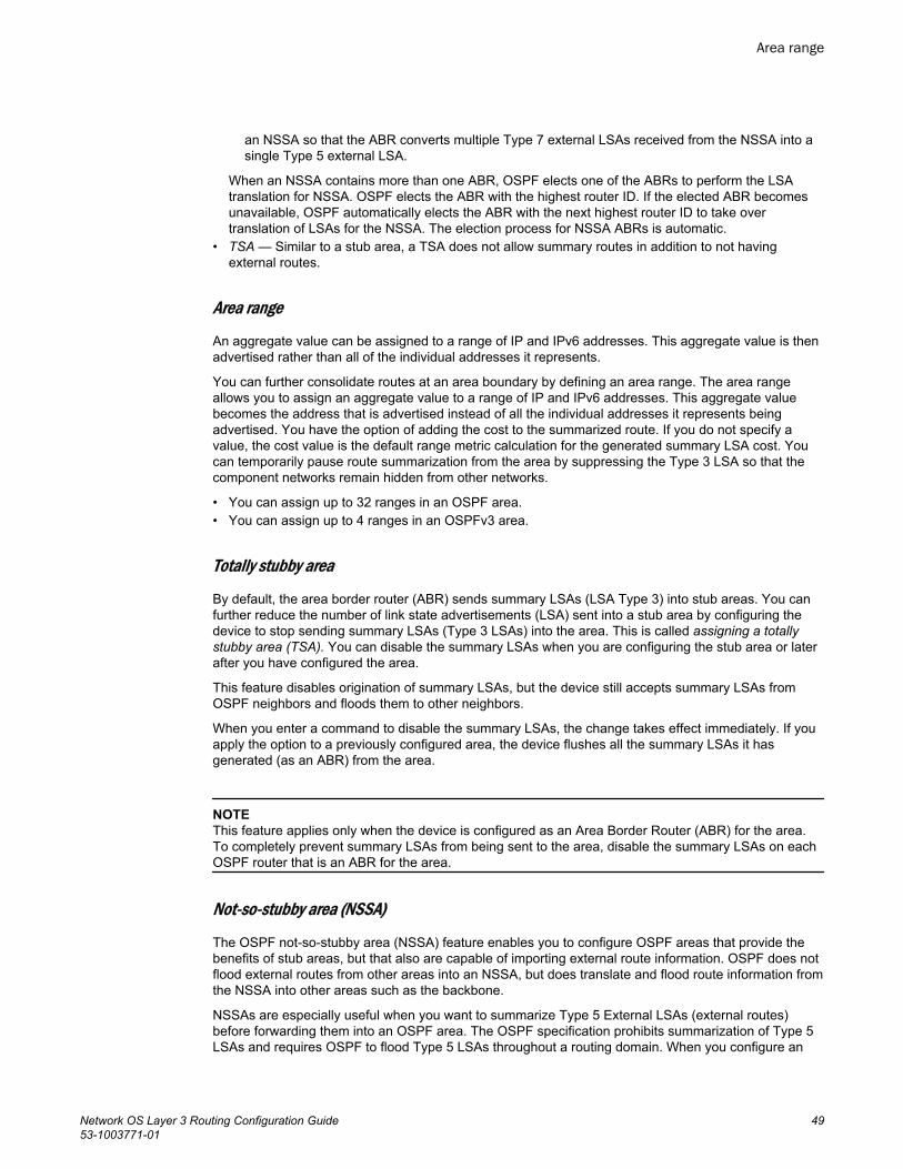
an NSSA so that the ABR converts multiple Type 7 external LSAs received from the NSSA into asingle Type 5 external LSA.
When an NSSA contains more than one ABR, OSPF elects one of the ABRs to perform the LSAtranslation for NSSA. OSPF elects the ABR with the highest router ID. If the elected ABR becomesunavailable, OSPF automatically elects the ABR with the next highest router ID to take overtranslation of LSAs for the NSSA. The election process for NSSA ABRs is automatic.
• TSA — Similar to a stub area, a TSA does not allow summary routes in addition to not havingexternal routes.
Area range
An aggregate value can be assigned to a range of IP and IPv6 addresses. This aggregate value is thenadvertised rather than all of the individual addresses it represents.
You can further consolidate routes at an area boundary by defining an area range. The area rangeallows you to assign an aggregate value to a range of IP and IPv6 addresses. This aggregate valuebecomes the address that is advertised instead of all the individual addresses it represents beingadvertised. You have the option of adding the cost to the summarized route. If you do not specify avalue, the cost value is the default range metric calculation for the generated summary LSA cost. Youcan temporarily pause route summarization from the area by suppressing the Type 3 LSA so that thecomponent networks remain hidden from other networks.
• You can assign up to 32 ranges in an OSPF area.• You can assign up to 4 ranges in an OSPFv3 area.
Totally stubby area
By default, the area border router (ABR) sends summary LSAs (LSA Type 3) into stub areas. You canfurther reduce the number of link state advertisements (LSA) sent into a stub area by configuring thedevice to stop sending summary LSAs (Type 3 LSAs) into the area. This is called assigning a totallystubby area (TSA). You can disable the summary LSAs when you are configuring the stub area or laterafter you have configured the area.
This feature disables origination of summary LSAs, but the device still accepts summary LSAs fromOSPF neighbors and floods them to other neighbors.
When you enter a command to disable the summary LSAs, the change takes effect immediately. If youapply the option to a previously configured area, the device flushes all the summary LSAs it hasgenerated (as an ABR) from the area.
NOTEThis feature applies only when the device is configured as an Area Border Router (ABR) for the area.To completely prevent summary LSAs from being sent to the area, disable the summary LSAs on eachOSPF router that is an ABR for the area.
Not-so-stubby area (NSSA)
The OSPF not-so-stubby area (NSSA) feature enables you to configure OSPF areas that provide thebenefits of stub areas, but that also are capable of importing external route information. OSPF does notflood external routes from other areas into an NSSA, but does translate and flood route information fromthe NSSA into other areas such as the backbone.
NSSAs are especially useful when you want to summarize Type 5 External LSAs (external routes)before forwarding them into an OSPF area. The OSPF specification prohibits summarization of Type 5LSAs and requires OSPF to flood Type 5 LSAs throughout a routing domain. When you configure an
Area range
Network OS Layer 3 Routing Configuration Guide 4953-1003771-01
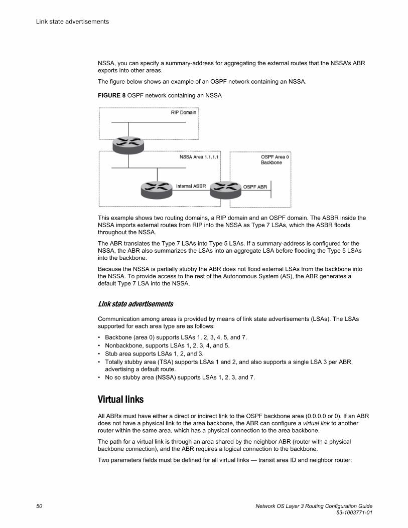
NSSA, you can specify a summary-address for aggregating the external routes that the NSSA's ABRexports into other areas.
The figure below shows an example of an OSPF network containing an NSSA.
FIGURE 8 OSPF network containing an NSSA
This example shows two routing domains, a RIP domain and an OSPF domain. The ASBR inside theNSSA imports external routes from RIP into the NSSA as Type 7 LSAs, which the ASBR floodsthroughout the NSSA.
The ABR translates the Type 7 LSAs into Type 5 LSAs. If a summary-address is configured for theNSSA, the ABR also summarizes the LSAs into an aggregate LSA before flooding the Type 5 LSAsinto the backbone.
Because the NSSA is partially stubby the ABR does not flood external LSAs from the backbone intothe NSSA. To provide access to the rest of the Autonomous System (AS), the ABR generates adefault Type 7 LSA into the NSSA.
Link state advertisements
Communication among areas is provided by means of link state advertisements (LSAs). The LSAssupported for each area type are as follows:
• Backbone (area 0) supports LSAs 1, 2, 3, 4, 5, and 7.• Nonbackbone, supports LSAs 1, 2, 3, 4, and 5.• Stub area supports LSAs 1, 2, and 3.• Totally stubby area (TSA) supports LSAs 1 and 2, and also supports a single LSA 3 per ABR,
advertising a default route.• No so stubby area (NSSA) supports LSAs 1, 2, 3, and 7.
Virtual linksAll ABRs must have either a direct or indirect link to the OSPF backbone area (0.0.0.0 or 0). If an ABRdoes not have a physical link to the area backbone, the ABR can configure a virtual link to anotherrouter within the same area, which has a physical connection to the area backbone.
The path for a virtual link is through an area shared by the neighbor ABR (router with a physicalbackbone connection), and the ABR requires a logical connection to the backbone.
Two parameters fields must be defined for all virtual links — transit area ID and neighbor router:
Link state advertisements
50 Network OS Layer 3 Routing Configuration Guide53-1003771-01
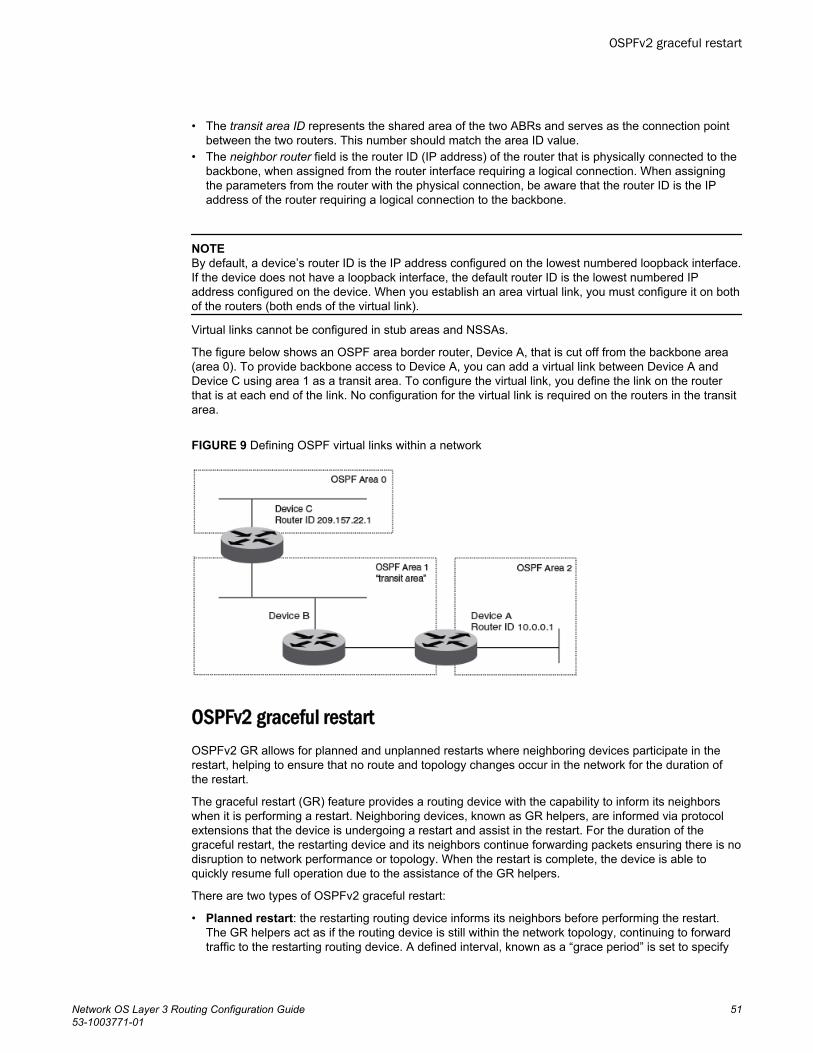
• The transit area ID represents the shared area of the two ABRs and serves as the connection pointbetween the two routers. This number should match the area ID value.
• The neighbor router field is the router ID (IP address) of the router that is physically connected to thebackbone, when assigned from the router interface requiring a logical connection. When assigningthe parameters from the router with the physical connection, be aware that the router ID is the IPaddress of the router requiring a logical connection to the backbone.
NOTEBy default, a device’s router ID is the IP address configured on the lowest numbered loopback interface.If the device does not have a loopback interface, the default router ID is the lowest numbered IPaddress configured on the device. When you establish an area virtual link, you must configure it on bothof the routers (both ends of the virtual link).
Virtual links cannot be configured in stub areas and NSSAs.
The figure below shows an OSPF area border router, Device A, that is cut off from the backbone area(area 0). To provide backbone access to Device A, you can add a virtual link between Device A andDevice C using area 1 as a transit area. To configure the virtual link, you define the link on the routerthat is at each end of the link. No configuration for the virtual link is required on the routers in the transitarea.
FIGURE 9 Defining OSPF virtual links within a network
OSPFv2 graceful restartOSPFv2 GR allows for planned and unplanned restarts where neighboring devices participate in therestart, helping to ensure that no route and topology changes occur in the network for the duration ofthe restart.
The graceful restart (GR) feature provides a routing device with the capability to inform its neighborswhen it is performing a restart. Neighboring devices, known as GR helpers, are informed via protocolextensions that the device is undergoing a restart and assist in the restart. For the duration of thegraceful restart, the restarting device and its neighbors continue forwarding packets ensuring there is nodisruption to network performance or topology. When the restart is complete, the device is able toquickly resume full operation due to the assistance of the GR helpers.
There are two types of OSPFv2 graceful restart:
• Planned restart: the restarting routing device informs its neighbors before performing the restart.The GR helpers act as if the routing device is still within the network topology, continuing to forwardtraffic to the restarting routing device. A defined interval, known as a “grace period” is set to specify
OSPFv2 graceful restart
Network OS Layer 3 Routing Configuration Guide 5153-1003771-01
when the neighbors should consider the restart complete and the restarting routing device as part ofthe network topology again.
• Unplanned restart: the routing device restarts without warning due to a software fault.
NOTEIn order for a graceful restart on a routing device to be successful, the OSPF neighbors must haveGR-helper mode enabled. GR-helper mode is enabled by default.
OSPF over VRFWith Network OS 4.0 and later, OSPF can run over multiple Virtual Routing and Forwarding (VRF)instances. OSPF maintains multiple instances of the routing protocol to exchange route informationamong various VRF instances. A multi-VRF-capable router maps an input interface to a unique VRF,based on user configuration. These input interfaces can be physical or a switched virtual interface(SVI). By default, all input interfaces are attached to the default VRF instance. All OSPF commandssupported in Network OS 4.0 and later are available over default and nondefault OSPF instances.
Multi-VRF for OSPF (also known as VRF-Lite for OSPF) provides a reliable mechanism for trustedVPNs to be built over a shared infrastructure. The ability to maintain multiple virtual routing orforwarding tables allows overlapping private IP addresses to be maintained across VPNs. For detailsand a configuration example, refer to "Multi-VRF for OSPF" in the chapter "Multi-VRF."
Multi-VRF for OSPF (also known as VRF-Lite for OSPF) provides a reliable mechanism for trustedVPNs to be built over a shared infrastructure. The ability to maintain multiple virtual routing orforwarding tables allows overlapping private IP addresses to be maintained across VPNs. For detailsand a configuration example, refer to "Multi-VRF for OSPF" in the chapter "Multi-VRF."
OSPF in a VCS environmentThe figure below shows one way in which OSPF can be used in a VCS fabric cluster environment.Routers RB1 and RB2, as well as the MLX switches, are configured with OSPF. Switches RB3, RB4,and RB5 are Layer 2 switches.
OSPF over VRF
52 Network OS Layer 3 Routing Configuration Guide53-1003771-01
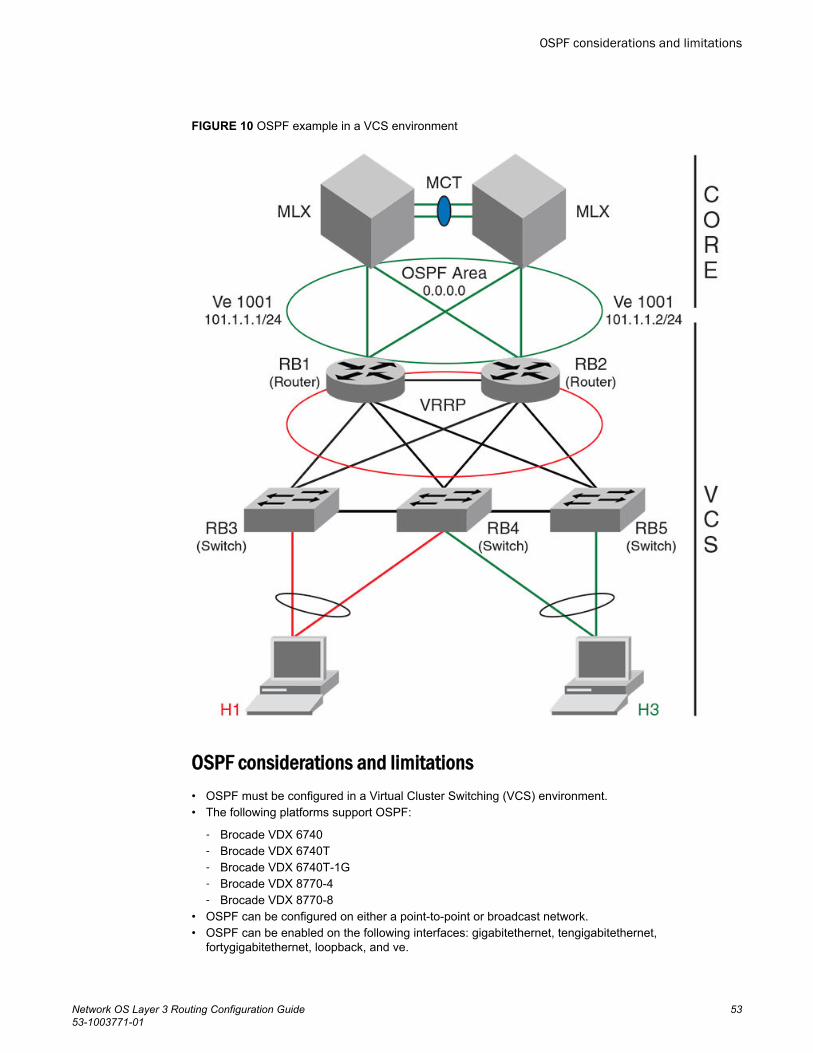
FIGURE 10 OSPF example in a VCS environment
OSPF considerations and limitations• OSPF must be configured in a Virtual Cluster Switching (VCS) environment.• The following platforms support OSPF:
‐ Brocade VDX 6740‐ Brocade VDX 6740T‐ Brocade VDX 6740T-1G‐ Brocade VDX 8770-4‐ Brocade VDX 8770-8
• OSPF can be configured on either a point-to-point or broadcast network.• OSPF can be enabled on the following interfaces: gigabitethernet, tengigabitethernet,
fortygigabitethernet, loopback, and ve.
OSPF considerations and limitations
Network OS Layer 3 Routing Configuration Guide 5353-1003771-01
• On enabling OSPF over a loopback interface, the network is advertised as a stub network in therouter LSA for the attached area. OSPF control packets, such as hellos , are not transmitted onloopback interfaces and adjacencies will not form.
• For VXLAN, if you are configuring a loopback interface to serve as a VTEP, you must manuallyconfigure distinct router-ids, using the ip router id command, for use by routing protocols.
Configuring OSPFConsider the topics discussed below when configuring OSPF.
Performing basic OSPF configurationThis section addresses the basics of OSPF configuration.
Enabling OSPF
To begin using OSPF on the router, perform these steps:
1. Follow the rules below.
• If a router is to operate as an ASBR, you must enable the ASBR capability at the system level.• Redistribution must be enabled on routers configured to operate as ASBRs.• All router ports must be assigned to one of the defined areas on an OSPF router. When a port is
assigned to an area, all corresponding subnets on that port are automatically included in theassignment.
2. Enter the router ospf command in RBridge ID configuration mode to enable OSPF on the router.This is shown in OSPF over VRF on page 52.
3. Assign the areas to which the router will be attached. Refer to Area types on page 48.4. Assign individual interfaces to the OSPF areas. Refer to Assigning interfaces to an area on page
56.5. Assign a virtual link to any ABR that does not have a direct link to the OSPF backbone area. Refer
to Virtual links on page 50.6. Refer to Changing default settings on page 61.
Setting up the backbone area
To set up the backbone area shown in Autonomous System on page 45, do the following:
1. In privileged EXEC mode on Router A, issue the configure command to enter global configurationmode.
2. Enter the rbridge-id command followed by the RBridge ID to enter RBridge configuration mode.3. Enter the router ospf command to enter OSPF configuration mode and enable OSPF on the router.4. Enter the area command and specify 0.0.0.0 to configure the backbone area.5. Enter the exit command until you return to global configuration mode.6. Enter the interface vlan command followed by the VLAN number to create a VLAN.7. Enter the rbridge-id command followed by the RBridge ID to enter RBridge configuration mode.8. Enter the interface ve command followed by the VLAN number to enter interface configuration
mode.
Configuring OSPF
54 Network OS Layer 3 Routing Configuration Guide53-1003771-01
9. Enter the ip address operand followed by the IP address/subnet for the interface.10.Issue the ip ospf area operand followed by the area ID to assign the interface to this area.
switch# configureswitch(config)# rbridge 10switch(config-rbridge-id-10)# router ospfswitch(config-router-ospf-vrf-default-vrf)# area 0.0.0.0switch(config-router-ospf-vrf-default-vrf)# exitswitch(config-rbridge-id-10)# exitswitch(config)# interface vlan 1001switch(config-Vlan-1001)# rbridge 10switch(config-rbridge-id-10)# interface Ve 1001switch(config-Ve-1001 # ip address 101.1.1.1/24switch(config-Ve-1001)# ip ospf area 0.0.0.0
Configuring an NSSA
To configure OSPF area 1.1.1.1 as an NSSA, do the following:
1. In privileged EXEC mode, enter the configure command to enter global configuration mode.2. Enter the rbridge-id command followed by the RBridge ID to enter RBridge configuration mode.3. Enter the router ospf command to enable OSPF on the router.4. Enter area followed by the area ID, then nssa followed by the NSSA ID.
switch# configureswitch(config)# rbridge-id 101switch(config-rbridge-id-101)# router ospfSwitch(config-router-ospf-vrf-default-vrf)# area 1.1.1.1 nssa 1
Configuring a summary-address for the NSSA
If you want the ABR that connects the NSSA to other areas to summarize the routes in the NSSAbefore translating them into Type 5 LSAs and flooding them into the other areas, configure a summary-address. The ABR creates an aggregate value based on the summary-address. The aggregate valuebecomes the address that the ABR advertises instead of advertising the individual addressesrepresented by the aggregate. You can configure up to 32 ranges in an OSPF area.
To configure a summary-address in NSSA 1.1.1.1 (this example assumes that you have alreadyconfigured NSSA 1.1.1.1.), do the following:
1. In privileged EXEC mode, issue the configure command to enter global configuration mode.2. Enter rbridge-id followed by the RBridge ID to enter RBridge configuration mode.3. Enter router ospf to enable OSPF on the router and to enter router OSPF configuration mode.4. Enter area followed by the area ID, then nssa followed by the NSSA ID.5. Enter summary-address followed by the IP address and mask for the summary route.
switch# configureswitch(config)# rbridge-id 101switch(config-rbridge-id-101)# router ospfswitch(config-router-ospf-vrf-default-vrf)# area 1.1.1.1 nssa 10switch(config-router-ospf-vrf-default-vrf)# summary-address 209.157.1.0 255.255.255.0
Disabling summary LSAs for a stub area
To disable summary LSAs for a stub area, enter a command such as the following:
switch(config-router-ospf-vrf-default-vrf)area 40 stub 99 no-summary
Configuring an NSSA
Network OS Layer 3 Routing Configuration Guide 5553-1003771-01
Assigning an area range (optional)
You can assign a range for an area, but it is not required. Ranges allow a specific IP address andmask to represent a range of IP addresses within an area, so that only that reference range address isadvertised to the network, instead of all the addresses within that range. Each area can have up to 32range addresses. For example, to define an area range for subnets on 0.0.0.10 and 0.0.0.20, do thefollowing:
1. In privileged EXEC mode, issue the configure command to enter global configuration mode.2. Issue the rbridge-id command followed by the RBridge ID to enter RBridge configuration mode.3. Issue the router ospf command to enable OSPF on the router.4. Issue the area operand followed by the area ID, then enter the range, and repeat as necessary.
switch# configureswitch(config)# rbridge-id 101switch(config-rbridge-id-101)# router ospfswitch(config-router-ospf-vrf-default-vrf)# area 0.0.0.10 range 192.45.0.0 255.255.0.0switch(config-router-ospf-vrf-default-vrf)# area 0.0.0.20 range 192.45.0.0 255.255.0.0
Assigning interfaces to an area
Once you define OSPF areas, you can assign interfaces to the areas. All router ports must beassigned to one of the defined areas on an OSPF router. When a port is assigned to an area, allcorresponding subnets on that port are automatically included in the assignment.
For example, to assign a tengigabitethernet interface 101/0/1 to a router area whose IP address is192.5.0.0, do the following:
1. In privileged EXEC mode, issue the configure command to enter global configuration mode.2. Issue the rbridge-id command followed by the RBridge ID to enter RBridge sub-configuration
mode.3. Issue the interface command followed by the interface ID to enter interface configuration mode.4. Issue the ip ospf area command followed by the IP address of the area.
switch# configureswitch(config)# rbridge-id 101switch(config-rbridge-id-101)# int te 101/0/1switch(conf-if-te-101/0/1)# ip ospf area 192.5.0.0If you want to set an interface to passive mode, use the ip ospf passive command. If you want toblock flooding of outbound LSAs on specific OSPF interfaces, use the ip ospf database-filter allout command.(Refer to the Network OS Command Reference for details.)
Configuring virtual links
Refer to Virtual links on page 50.
Do the following to configure virtual links. To define the virtual link on Device A:
1. In privileged EXEC mode, issue the configure command to enter global configuration mode.2. Enter the rbridge-id command followed by the RBridge ID to enter RBridge configuration mode.3. Enter the router ospf command to enable OSPF on the router.4. Enter the area operand followed by the area ID, and repeat as necessary.
Assigning an area range (optional)
56 Network OS Layer 3 Routing Configuration Guide53-1003771-01
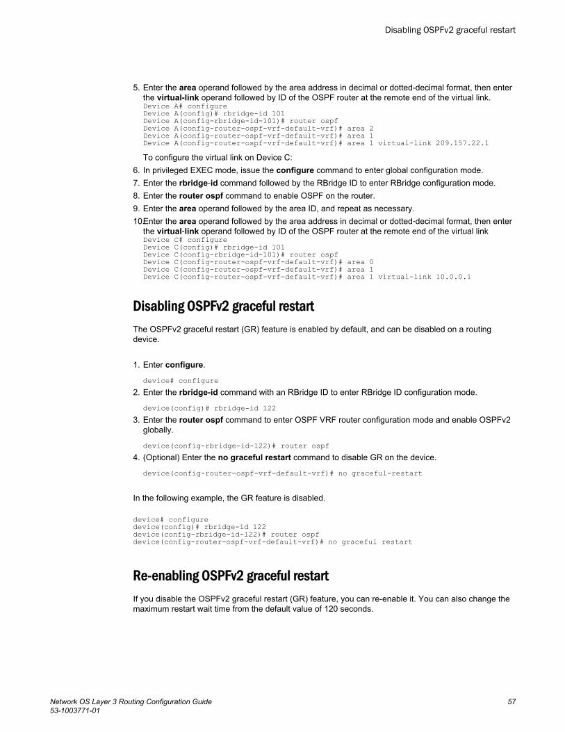
5. Enter the area operand followed by the area address in decimal or dotted-decimal format, then enterthe virtual-link operand followed by ID of the OSPF router at the remote end of the virtual link.Device A# configureDevice A(config)# rbridge-id 101Device A(config-rbridge-id-101)# router ospfDevice A(config-router-ospf-vrf-default-vrf)# area 2Device A(config-router-ospf-vrf-default-vrf)# area 1Device A(config-router-ospf-vrf-default-vrf)# area 1 virtual-link 209.157.22.1To configure the virtual link on Device C:
6. In privileged EXEC mode, issue the configure command to enter global configuration mode.7. Enter the rbridge‐id command followed by the RBridge ID to enter RBridge configuration mode.8. Enter the router ospf command to enable OSPF on the router.9. Enter the area operand followed by the area ID, and repeat as necessary.10.Enter the area operand followed by the area address in decimal or dotted‐decimal format, then enter
the virtual‐link operand followed by ID of the OSPF router at the remote end of the virtual linkDevice C# configureDevice C(config)# rbridge-id 101Device C(config-rbridge-id-101)# router ospfDevice C(config-router-ospf-vrf-default-vrf)# area 0Device C(config-router-ospf-vrf-default-vrf)# area 1Device C(config-router-ospf-vrf-default-vrf)# area 1 virtual-link 10.0.0.1
Disabling OSPFv2 graceful restartThe OSPFv2 graceful restart (GR) feature is enabled by default, and can be disabled on a routingdevice.
1. Enter configure.
device# configure2. Enter the rbridge-id command with an RBridge ID to enter RBridge ID configuration mode.
device(config)# rbridge-id 1223. Enter the router ospf command to enter OSPF VRF router configuration mode and enable OSPFv2
globally.
device(config-rbridge-id-122)# router ospf4. (Optional) Enter the no graceful restart command to disable GR on the device.
device(config-router-ospf-vrf-default-vrf)# no graceful-restart
In the following example, the GR feature is disabled.
device# configuredevice(config)# rbridge-id 122device(config-rbridge-id-122)# router ospf device(config-router-ospf-vrf-default-vrf)# no graceful restart
Re-enabling OSPFv2 graceful restartIf you disable the OSPFv2 graceful restart (GR) feature, you can re-enable it. You can also change themaximum restart wait time from the default value of 120 seconds.
Disabling OSPFv2 graceful restart
Network OS Layer 3 Routing Configuration Guide 5753-1003771-01
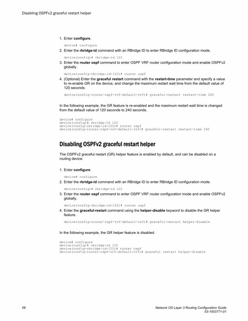
1. Enter configure.
device# configure2. Enter the rbridge-id command with an RBridge ID to enter RBridge ID configuration mode.
device(config)# rbridge-id 1223. Enter the router ospf command to enter OSPF VRF router configuration mode and enable OSPFv2
globally.
device(config-rbridge-id-122)# router ospf4. (Optional) Enter the graceful restart command with the restart-time parameter and specify a value
to re-enable GR on the device, and change the maximum restart wait time from the default value of120 seconds.
device(config-router-ospf-vrf-default-vrf)# graceful-restart restart-time 240
In the following example, the GR feature is re-enabled and the maximum restart wait time is changedfrom the default value of 120 seconds to 240 seconds.
device# configuredevice(config)# rbridge-id 122device(config-rbridge-id-122)# router ospf device(config-router-ospf-vrf-default-vrf)# graceful-restart restart-time 240
Disabling OSPFv2 graceful restart helperThe OSPFv2 graceful restart (GR) helper feature is enabled by default, and can be disabled on arouting device.
1. Enter configure.
device# configure2. Enter the rbridge-id command with an RBridge ID to enter RBridge ID configuration mode.
device(config)# rbridge-id 1223. Enter the router ospf command to enter OSPF VRF router configuration mode and enable OSPFv2
globally.
device(config-rbridge-id-122)# router ospf4. Enter the graceful-restart command using the helper-disable keyword to disable the GR helper
feature.
device(config-router-ospf-vrf-default-vrf)# graceful-restart helper-disable
In the following example, the GR helper feature is disabled.
device# configuredevice(config)# rbridge-id 122device(config-rbridge-id-122)# router ospf device(config-router-ospf-vrf-default-vrf)# graceful restart helper-disable
Disabling OSPFv2 graceful restart helper
58 Network OS Layer 3 Routing Configuration Guide53-1003771-01

OSPFv2 non-stop routing (NSR)OSPFv2 can continue operation without interruption during hitless failover when the NSR feature isenabled.
In graceful restart (GR), the restarting neighbors need to help build routing information during a failover.However, the GR helper may not be supported by all devices in a network. The non-stop routing (NSR)feature eliminates this dependency.
NSR does not require support from neighboring devices to perform hitless failover, and OSPF cancontinue operation without interruption.
NOTENSR does not support IPv6-over-IPv4 tunnel and virtual link, so traffic loss is expected while performinghitless failover.
Configuring the OSPFv2 Max-Metric Router LSABy configuring the OSPFv2 max-metric router LSA feature you can enable OSPFv2 to advertise itslocally generated router LSAs with a maximum metric.
1. Enter the configure terminal command to access global configuration mode.
device# configure terminal2. Enter the rbridge-id command with an RBridge ID to enter RBridge ID configuration mode.
device(config)# rbridge-id 1223. Enter the ip router-id command to specify the router ID.
device(config-rbridge-id-122)# ip router-id 10.11.12.134. Enter the ip router ospf command to enter IPv6 OSPF configuration mode and enable OSPFv3 on
the router.
device(config-rbridge-id-122)# router ospf5. Enter the max-metric router-lsa command with the on-startup keyword and specify a value to
specify a period of time to advertise a maximum metric after a restart before advertising with anormal metric.
device(config-router-ospf-vrf-default-vrf)# max-metric router-lsa on-startup 85
This example configures an OSPFv2 device to advertise a maximum metric for 85 seconds after arestart before advertising with a normal metric .
device# configuredevice(config)# rbridge-id 122device(config-rbridge-id-122)# ip router-id 10.11.12.13device(config-rbridge-id-122)# router ospf device(config-router-ospf-vrf-default-vrf)# max-metric router-lsa max-metric router-lsa on-startup 85
OSPFv2 non-stop routing (NSR)
Network OS Layer 3 Routing Configuration Guide 5953-1003771-01
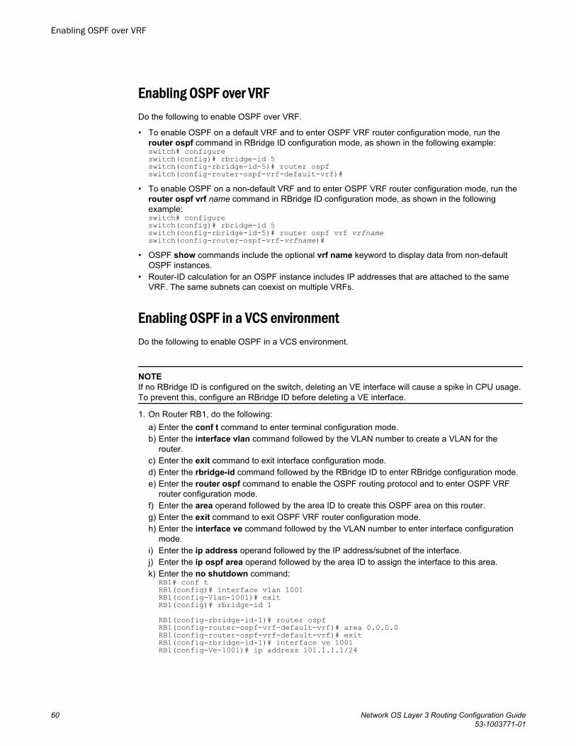
Enabling OSPF over VRFDo the following to enable OSPF over VRF.
• To enable OSPF on a default VRF and to enter OSPF VRF router configuration mode, run therouter ospf command in RBridge ID configuration mode, as shown in the following example:switch# configureswitch(config)# rbridge-id 5switch(config-rbridge-id-5)# router ospfswitch(config-router-ospf-vrf-default-vrf)#
• To enable OSPF on a non-default VRF and to enter OSPF VRF router configuration mode, run therouter ospf vrf name command in RBridge ID configuration mode, as shown in the followingexample:switch# configureswitch(config)# rbridge-id 5switch(config-rbridge-id-5)# router ospf vrf vrfnameswitch(config-router-ospf-vrf-vrfname)#
• OSPF show commands include the optional vrf name keyword to display data from non-defaultOSPF instances.
• Router-ID calculation for an OSPF instance includes IP addresses that are attached to the sameVRF. The same subnets can coexist on multiple VRFs.
Enabling OSPF in a VCS environmentDo the following to enable OSPF in a VCS environment.
NOTEIf no RBridge ID is configured on the switch, deleting an VE interface will cause a spike in CPU usage.To prevent this, configure an RBridge ID before deleting a VE interface.
1. On Router RB1, do the following:a) Enter the conf t command to enter terminal configuration mode.b) Enter the interface vlan command followed by the VLAN number to create a VLAN for the
router.c) Enter the exit command to exit interface configuration mode.d) Enter the rbridge-id command followed by the RBridge ID to enter RBridge configuration mode.e) Enter the router ospf command to enable the OSPF routing protocol and to enter OSPF VRF
router configuration mode.f) Enter the area operand followed by the area ID to create this OSPF area on this router.g) Enter the exit command to exit OSPF VRF router configuration mode.h) Enter the interface ve command followed by the VLAN number to enter interface configuration
mode.i) Enter the ip address operand followed by the IP address/subnet of the interface.j) Enter the ip ospf area operand followed by the area ID to assign the interface to this area.k) Enter the no shutdown command:
RB1# conf tRB1(config)# interface vlan 1001RB1(config-Vlan-1001)# exitRB1(config)# rbridge-id 1 RB1(config-rbridge-id-1)# router ospfRB1(config-router-ospf-vrf-default-vrf)# area 0.0.0.0RB1(config-router-ospf-vrf-default-vrf)# exitRB1(config-rbridge-id-1)# interface ve 1001RB1(config-Ve-1001)# ip address 101.1.1.1/24
Enabling OSPF over VRF
60 Network OS Layer 3 Routing Configuration Guide53-1003771-01
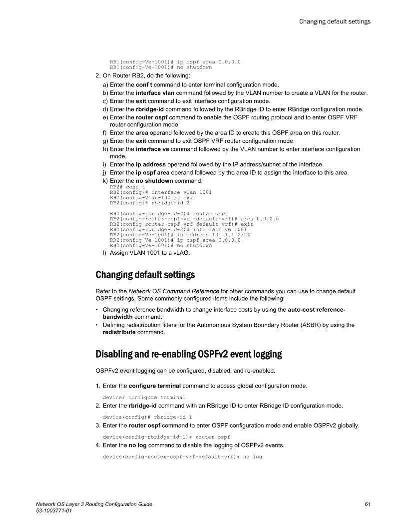
RB1(config-Ve-1001)# ip ospf area 0.0.0.0RB1(config-Ve-1001)# no shutdown
2. On Router RB2, do the following:a) Enter the conf t command to enter terminal configuration mode.b) Enter the interface vlan command followed by the VLAN number to create a VLAN for the router.c) Enter the exit command to exit interface configuration mode.d) Enter the rbridge-id command followed by the RBridge ID to enter RBridge configuration mode.e) Enter the router ospf command to enable the OSPF routing protocol and to enter OSPF VRF
router configuration mode.f) Enter the area operand followed by the area ID to create this OSPF area on this router.g) Enter the exit command to exit OSPF VRF router configuration mode.h) Enter the interface ve command followed by the VLAN number to enter interface configuration
mode.i) Enter the ip address operand followed by the IP address/subnet of the interface.j) Enter the ip ospf area operand followed by the area ID to assign the interface to this area.k) Enter the no shutdown command:
RB2# conf tRB2(config)# interface vlan 1001RB2(config-Vlan-1001)# exitRB2(config)# rbridge-id 2 RB2(config-rbridge-id-2)# router ospfRB2(config-router-ospf-vrf-default-vrf)# area 0.0.0.0RB2(config-router-ospf-vrf-default-vrf)# exitRB2(config-rbridge-id-2)# interface ve 1001RB2(config-Ve-1001)# ip address 101.1.1.2/24RB2(config-Ve-1001)# ip ospf area 0.0.0.0RB2(config-Ve-1001)# no shutdown
l) Assign VLAN 1001 to a vLAG.
Changing default settingsRefer to the Network OS Command Reference for other commands you can use to change defaultOSPF settings. Some commonly configured items include the following:
• Changing reference bandwidth to change interface costs by using the auto-cost reference-bandwidth command.
• Defining redistribution filters for the Autonomous System Boundary Router (ASBR) by using theredistribute command.
Disabling and re-enabling OSPFv2 event loggingOSPFv2 event logging can be configured, disabled, and re-enabled.
1. Enter the configure terminal command to access global configuration mode.
device# configure terminal2. Enter the rbridge-id command with an RBridge ID to enter RBridge ID configuration mode.
device(config)# rbridge-id 13. Enter the router ospf command to enter OSPF configuration mode and enable OSPFv2 globally.
device(config-rbridge-id-1)# router ospf4. Enter the no log command to disable the logging of OSPFv2 events.
device(config-router-ospf-vrf-default-vrf)# no log
Changing default settings
Network OS Layer 3 Routing Configuration Guide 6153-1003771-01
The following example re-enables the logging of all OSPFv2 events.device# configure terminaldevice(config)# rbridge-id 1device(config-rbridge-id-1)# router ospf device(config-router-ospf-vrf-default-vrf)# log all
Disabling OSPF on the routerConsider the topics discussed below when disabling OSPF.
Understanding the effects of disabling OSPF
Consider the following before disabling OSPF on a router:
• If you disable OSPF, the device removes all the configuration information for the disabled protocolfrom the running configuration. Moreover, when you save the configuration to the startupconfiguration file after disabling one of these protocols, all the configuration information for thedisabled protocol is removed from the startup configuration file.
• If you are testing an OSPF configuration and are likely to disable and re-enable the protocol, youmight want to make a backup copy of the startup configuration file containing the protocol’sconfiguration information. This way, if you remove the configuration information by saving theconfiguration after disabling the protocol, you can restore the configuration by copying the backupcopy of the startup configuration file into the flash memory.
• If the management default route information is available in the Chassis ID (CID) card, the OSPFdefault route is overwritten by the management default route when the switch reboots. In order toprevent this, remove the management default route after the switch reboots. The OSPF defaultroute is automatically re-instated. Refer to the “Using the Chassis ID (CID) Recovery Tool ”chapterin the Network OS Software Troubleshooting Guide.
Disabling OSPF
To disable OSPF on the router, use the no router ospf command:
1. In privileged EXEC mode, issue the configure command to enter global configuration mode.2. Enter the rbridge-id command followed by the RBridge ID to enter RBridge configuration mode.3. Issue the no router ospf command to disable OSPF on the router.
switch# configureswitch(config)# rbridge-id 101switch(config-rbridge-id-101)# no router ospf
Disabling OSPF on the router
62 Network OS Layer 3 Routing Configuration Guide53-1003771-01
OSPFv3
● OSPFv3 overview........................................................................................................... 63● OSPFv3 considerations and limitations.......................................................................... 64● OSPFv3 areas.................................................................................................................64● Virtual links......................................................................................................................67● OSPFv3 route redistribution............................................................................................69● Default route origination.................................................................................................. 70● Filtering OSPFv3 routes..................................................................................................71● SPF timers...................................................................................................................... 71● OSPFv3 administrative distance..................................................................................... 71● OSPFv3 LSA refreshes...................................................................................................72● OSPFv3 over VRF.......................................................................................................... 72● OSPFv3 graceful restart helper.......................................................................................73● OSPFv3 non-stop routing (NSR).....................................................................................73● IPsec for OSPFv3........................................................................................................... 73● IPsec for OSPFv3 configuration......................................................................................75● Configuring OSPFv3....................................................................................................... 75
OSPFv3 overviewIPv6 supports OSPF Version 3 (OSPFv3). OSPFv3 functions similarly to OSPF Version 2 (OSPFv2),with several enhancements.
Open Shortest Path First (OSPF) is a link-state routing protocol. OSPF uses link-state advertisements(LSAs) to update neighboring routers about its interfaces and information on those interfaces. A devicefloods LSAs to all neighboring routers to update them about the interfaces. Each router maintains anidentical database that describes its area topology to help a router determine the shortest path betweenit and any neighboring router.
IPv6 supports OSPF Version 3 (OSPFv3), which functions similarly to OSPF Version 2 (OSPFv2), theversion that IPv4 supports, except for the following enhancements:
• Support for IPv6 addresses and prefixes.• Ability to configure several IPv6 addresses on a device interface. (While OSPFv2 runs per IP subnet,
OSPFv3 runs per link. In general, you can configure several IPv6 addresses on a router interface,but OSPFv3 forms one adjacency per interface only, using the interface associated link-local addressas the source for OSPF protocol packets. On virtual links, OSPFv3 uses the global IP address as thesource. OSPFv3 imports all or none of the address prefixes configured on a router interface. Youcannot select the addresses to import.)
• Ability to run one instance of OSPFv2 and one instance of OSPFv3 concurrently on a link.• Support for IPv6 link-state advertisements (LSAs).
NOTEAlthough OSPFv2 and OSPFv3 function in a similar manner, Brocade has implemented the userinterface for each version independently of the other. Therefore, any configuration of OSPFv2 featureswill not affect the configuration of OSPFv3 features and vice versa.
Network OS Layer 3 Routing Configuration Guide 6353-1003771-01
NOTEYou are required to configure a router ID when running only IPv6 routing protocols.
OSPFv3 considerations and limitationsThere are a number of things to consider when configuring OSPFv3.
• OSPFv3 must be configured in a VCS environment.• OSPFv3 can be configured on either a point-to-point or broadcast network.• OSPFv3 can be enabled on the following interfaces: gigabitethernet, tengigabitethernet,
fortygigabitethernet, hundredgigabitethenet, loopback, and ve.• On enabling OSPFv3 over a loopback interface, the network is advertised as a stub network in the
router LSA for the attached area. OSPFv3 control packets, such as hellos , are not transmitted onloopback interfaces and adjacencies will not form.
OSPFv3 areasIPv6 addresses or a number can be assigned as the area ID for an OSPFv3 area.
After OSPFv3 is enabled, you can assign OSPFv3 areas. You can assign an IPv6 address or anumber as the area ID for each area. The area ID is representative of all IPv4 addresses (subnets) ona device interface. Each device interface can support one area.
NOTEYou can assign only one area on a device interface.
Backbone areaThe backbone area forms the core of OSPF and OSPFv3 networks. All OSPF and OSPFv3 areas areconnected to the backbone area.
The backbone area (also known as area 0 or area 0.0.0.0) forms the core of OSPF and OSPFv3networks. All other areas are connected to it, and inter-area routing happens by way of routersconnected to the backbone area and to their own associated areas. The backbone area is the logicaland physical structure for the OSPF domain and is attached to all non-zero areas in the OSPFdomain.
The backbone area is responsible for distributing routing information between non-backbone areas.The backbone must be contiguous, but it does not need to be physically contiguous; backboneconnectivity can be established and maintained through the configuration of virtual links.
OSPFv3 considerations and limitations
64 Network OS Layer 3 Routing Configuration Guide53-1003771-01
Area typesOSPFv3 areas can be normal, a stub area, a totally stubby area, or a not-so-stubby area (NSSA).
• Normal - OSPFv3 devices within a normal area can send and receive External Link StateAdvertisements (LSAs).
• Stub - OSPFv3 devices within a stub area cannot send or receive External LSAs. In addition, OSPFdevices in a stub area must use a default route to the area’s Area Border Router (ABR) to send trafficout of the area.
• TSA – Similar to a stub area, a TSA does not allow summary routes in addition to not having externalroutes.
• NSSA - The ASBR of an NSSA can import external route information into the area.
‐ ASBRs redistribute (import) external routes into the NSSA as type 7 LSAs. Type 7 External LSAsare a special type of LSA generated only by ASBRs within an NSSA, and are flooded to all therouters within only that NSSA.
‐ ABRs translate type 7 LSAs into type 5 External LSAs, which can then be flooded throughout theautonomous system. The NSSA translator converts type 7 LSA to type 5 LSA, if F-bit and P-bit areset and there is a reachable forwarding address. ABR translates to type 5 only when P bit is set intype 7 LSA.
When an NSSA contains more than one ABR, OSPFv3 elects one of the ABRs to perform the LSAtranslation for NSSA. OSPF elects the ABR with the highest router ID. If the elected ABR becomesunavailable, OSPFv3 automatically elects the ABR with the next highest router ID to take overtranslation of LSAs for the NSSA. The election process for NSSA ABRs is automatic.
Area rangeAn aggregate value can be assigned to a range of IP and IPv6 addresses. This aggregate value is thenadvertised rather than all of the individual addresses it represents.
You can further consolidate routes at an area boundary by defining an area range. The area rangeallows you to assign an aggregate value to a range of IP and IPv6 addresses. This aggregate valuebecomes the address that is advertised instead of all the individual addresses it represents beingadvertised. You have the option of adding the cost to the summarized route. If you do not specify avalue, the cost value is the default range metric calculation for the generated summary LSA cost. Youcan temporarily pause route summarization from the area by suppressing the Type 3 LSA so that thecomponent networks remain hidden from other networks.
• You can assign up to 32 ranges in an OSPF area.• You can assign up to 4 ranges in an OSPFv3 area.
Stub areaA stub area is an area in which you don't allow advertisements of external routes, reducing the size ofthe database. The number of LSAs sent into a stub area can be reduced.
By default, the Area Border Router (ABR) sends summary LSAs (type 3 LSAs) into stub areas. You canreduce the number of LSAs sent into a stub area by configuring the device to stop sending summaryLSAs into the area. You can disable the summary LSAs when you are configuring the stub area or afteryou have configured the area.
The area stub no-summary feature disables origination of summary LSAs into a stub area, but thedevice still accepts summary LSAs from OSPFv3 neighbors and floods them to other areas. The devicecan form adjacencies with other routers regardless of whether summarization is enabled or disabled forareas on each router.
Area types
Network OS Layer 3 Routing Configuration Guide 6553-1003771-01
When you disable the summary LSAs, the change takes effect immediately. If you apply the option toa previously configured area, the device flushes all of the summary LSAs it has generated (as anABR) from the area.
NOTEThis feature applies only when the Brocade device is configured as an Area Border Router (ABR) forthe area. To completely prevent summary LSAs from being sent to the area, disable the summaryLSAs on each OSPFv3 router that is an ABR for the area.
Totally stubby areaBy default, the area border router (ABR) sends summary LSAs (LSA Type 3) into stub areas. You canfurther reduce the number of link state advertisements (LSA) sent into a stub area by configuring thedevice to stop sending summary LSAs (Type 3 LSAs) into the area. This is called assigning a totallystubby area (TSA). You can disable the summary LSAs when you are configuring the stub area orlater after you have configured the area.
This feature disables origination of summary LSAs, but the device still accepts summary LSAs fromOSPF neighbors and floods them to other neighbors.
When you enter a command to disable the summary LSAs, the change takes effect immediately. If youapply the option to a previously configured area, the device flushes all the summary LSAs it hasgenerated (as an ABR) from the area.
NOTEThis feature applies only when the device is configured as an Area Border Router (ABR) for the area.To completely prevent summary LSAs from being sent to the area, disable the summary LSAs oneach OSPF router that is an ABR for the area.
Not-so-stubby areaNSSAs are OSPFv3 areas that provide the benefits of stub areas with the extra capability of importingexternal route information.
The OSPFv3 not-so-stubby-area (NSSA) enables you to configure OSPFv3 areas that provide thebenefits of stub areas, but that also are capable of importing external route information. OSPFv3 doesnot flood external routes from other areas into an NSSA, but does translate and flood route informationfrom the NSSA into other areas such as the backbone.
NSSAs are especially useful when you want to advertise type 5 External LSAs (external routes) beforeforwarding them into an OSPFv3 area. The OSPFv3 specification (RFC 5340) prohibits the advertisingof type 5 LSAs and requires OSPFv3 to flood type 5 LSAs throughout a routing domain. When youconfigure a NSSA, you can specify an address range for aggregating the external routes that the ABRof the NSSAs exports into other areas.
You can block the generation of type 3 and type 7 LSAs into an NSSA. You can also configure theNSSAs translator role. If the router is an ABR, a type 3 summary LSA is originated into the NSSA. Ifthe router is an ASBR, type 7 NSSA External LSA is generated into the NSSA with a default externalmetric value of 10. The router's NSSA translator role is set to candidate and the router participates inNSSA translation election.
In the case where an ASBR should generate type 5 LSA into normal areas and should not generatetype 7 LSA into a NSSA, you can prevent an NSSA ABR from generating type 7 LSA into a NSSA.
Totally stubby area
66 Network OS Layer 3 Routing Configuration Guide53-1003771-01
If the router is an ABR, you can prevent any type 3 and type 4 LSA from being injected into the area.The only exception is that a default route is injected into the NSSA by the ABR, and strictly as a type 3LSA.
LSA types for OSPFv3Communication among OSPFv3 areas is provided by means of link state advertisements (LSAs).OSPFv3 supports a number of types of LSAs.
• Router LSAs (Type 1)• Network LSAs (Type 2)• Interarea-prefix LSAs for ABRs (Type 3)• Interarea-router LSAs for ASBRs (Type 4)• Autonomous system External LSAs (Type 5)• Group Membership LSA (Type 6)• NSSA External LSAs (Type 7)• Link LSAs (Type 8)• Intra-area-prefix LSAs (Type 9)
For more information about these LSAs, refer to RFC 5340.
Virtual linksIf an ABR does not have a physical link to a backbone area, a virtual link can be configured from theABR to another device within the same area that has a physical connection to the backbone area.
All ABRs must have either a direct or indirect link to an OSPFv3 backbone area (0 or 0.0.0.0). If an ABRdoes not have a physical link to a backbone area, you can configure a virtual link from the ABR toanother router within the same area that has a physical connection to the backbone area.
The path for a virtual link is through an area shared by the neighbor ABR (router with a physicalbackbone connection) and the ABR requiring a logical connection to the backbone.
In the figure below a virtual link has been created between ABR1 and ABR2. ABR1 has a direct link tothe backbone area, while ABR2 has an indirect link to the backbone area through Area 1.
LSA types for OSPFv3
Network OS Layer 3 Routing Configuration Guide 6753-1003771-01
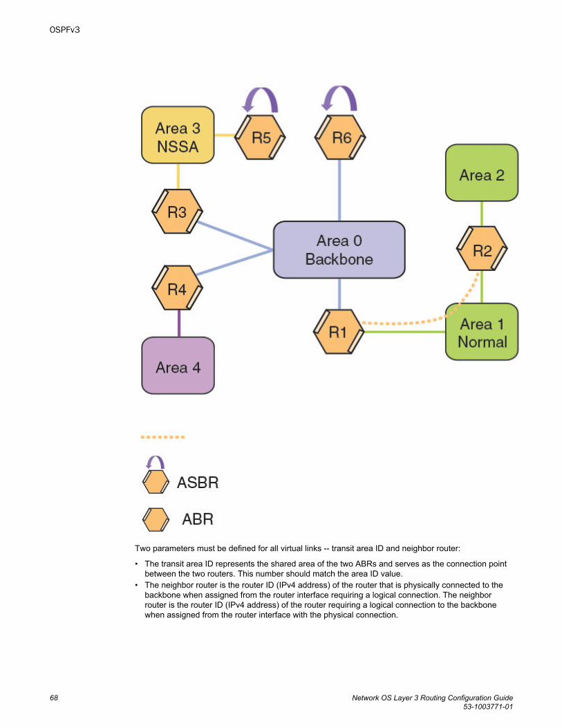
Two parameters must be defined for all virtual links -- transit area ID and neighbor router:
• The transit area ID represents the shared area of the two ABRs and serves as the connection pointbetween the two routers. This number should match the area ID value.
• The neighbor router is the router ID (IPv4 address) of the router that is physically connected to thebackbone when assigned from the router interface requiring a logical connection. The neighborrouter is the router ID (IPv4 address) of the router requiring a logical connection to the backbonewhen assigned from the router interface with the physical connection.
OSPFv3
68 Network OS Layer 3 Routing Configuration Guide53-1003771-01
NOTEBy default, the router ID is the IPv4 address configured on the lowest-numbered loopback interface. Ifthe device does not have a loopback interface, the default router ID is the highest-numbered IPv4address configured on the device.
When you establish an area virtual link, you must configure it on both ends of the virtual link. Forexample, imagine that ABR1 in areas 1 and 2 is cut off from the backbone area (area 0). To providebackbone access to ABR1, you can add a virtual link between ABR1 and ABR2 in area 1 using area 1as a transit area. To configure the virtual link, you define the link on the router that is at each end of thelink. No configuration for the virtual link is required on the routers in the transit area.
Virtual links cannot be configured in stub areas and NSSAs.
Virtual link source address assignmentWhen routers at both ends of a virtual link communicate, the source address included in the packetsmust be a global IPv6 address that is automatically selected for each transit area.
When routers at both ends of a virtual link communicate with one another, the source address includedin the packets must be a global IPv6 address. A global IPv6 address is automatically selected for eachtransit area and this address is advertised into the transit area of the intra-area-prefix LSA. Theautomatically selected global IPv6 address for a transit area is the first global IPv6 address of anyloopback interface in the transit area. If no global IPv6 address is available on a loopback interface inthe area, the first global IPv6 address of the lowest-numbered interface in the UP state (belonging to thetransit area) is assigned. If no global IPv6 address is configured on any of the OSPFv3 interfaces in thetransit area, the virtual links in the transit area do not operate. The automatically selected IPv6 globaladdress is updated whenever the previously selected IPv6 address of the interface changes, isremoved, or if the interface goes down.
NOTEThe existing selected virtual link address does not change because the global IPv6 address is nowavailable on a loopback interface or a lower-numbered interface in the transit area. To force the globalIPv6 address for the virtual link to be the global IPv6 address of a newly configured loopback, or alower-numbered interface in the area, you must either disable the existing selected interface or removethe currently selected global IPv6 address from the interface.
OSPFv3 route redistributionRoutes from various sources can be redistributed into OSPFv3. These routes can be redistributed in anumber of ways.
You can configure the device to redistribute routes from the following sources into OSPFv3:
• IPv6 static routes• Directly connected IPv6 networks• BGP4+
You can redistribute routes in the following ways:
• By route types. For example, the Brocade device redistributes all IPv6 static routes.• By using a route map to filter which routes to redistribute. For example, the device redistributes
specified IPv6 static routes only.
Virtual link source address assignment
Network OS Layer 3 Routing Configuration Guide 6953-1003771-01
NOTEYou must configure the route map before you configure a redistribution filter that uses the route map.
NOTEWhen you use a route map for route redistribution, the software disregards the permit or deny action ofthe route map.
NOTEFor an external route that is redistributed into OSPFv3 through a route map, the metric value of theroute remains the same unless the metric is set by the set metric command inside the route map orthe default-metric command. For a route redistributed without using a route map, the metric is set bythe metric parameter if set or the default-metric command if the metric parameter is not set.
NOTEThe CLI VRF-lite-capability present in OSPFv2 is not present in OSPFv3. Therefore, when a BGProute is redistributed from an MPLS domain into OSPFv3 and the DN (down) bit is set, the routes mustbe installed in the OSPFv3 routing table. Such routes could get propagated back into the MLPS cloudif there are OSPFv3 back-door links configured.
Default route originationAn ASBR can be configured to automatically advertise a default external route into an OSPFv3 routingdomain.
When the Brocade device is an OSPFv3 Autonomous System Boundary Router (ASBR), you canconfigure it to automatically generate a default external route into an OSPFv3 routing domain.
By default, the Brocade device does not advertise the default route into the OSPFv3 domain. If youwant the device to advertise the OSPFv3 default route, you must explicitly enable default routeorigination.
When you enable OSPFv3 default route origination, the device advertises a type 5 default route that isflooded throughout the autonomous system, with the exception of stub areas.
The device advertises the default route into OSPFv3 even if OSPFv3 route redistribution is notenabled, and even if the default route is learned through an IBGP neighbor. The router does not,however, originate the default route if the active default route is learned from an OSPFv3 router in thesame domain.
NOTEThe Brocade device does not advertise the OSPFv3 default route, regardless of other configurationparameters, unless you explicitly enable default route origination.
If default route origination is enabled and you disable it, the default route originated by the device isflushed. Default routes generated by other OSPFv3 routers are not affected. If you re-enable thedefault route origination, the change takes effect immediately and you do not need to reload thesoftware.
Default route origination
70 Network OS Layer 3 Routing Configuration Guide53-1003771-01
Filtering OSPFv3 routesYou can filter the routes to be placed in the OSPFv3 route table by configuring distribution lists.OSPFv3 distribution lists can be applied globally or to an interface.
The functionality of OSPFv3 distribution lists is similar to that of OSPFv2 distribution lists.
SPF timersThe device uses a SPF delay timer and a SPF hold time timer to calculate the shortest path for OSPFv3routes. The values for both timers can be changed.
The Brocade device uses the following timers when calculating the shortest path for OSPFv3 routes:
• SPF delay - When the Brocade device receives a topology change, the device waits before it starts aShortest Path First (SPF) calculation. By default, the device waits 5 seconds. You can configure theSPF delay to a value from 0 through 65535 seconds. If you set the SPF delay to 0 seconds, thedevice immediately begins the SPF calculation after receiving a topology change.
• SPF hold time - The device waits a specific amount of time between consecutive SPF calculations.By default, it waits 10 seconds. You can configure the SPF hold time to a value from 0 through 65535seconds. If you set the SPF hold time to 0 seconds, the device does not wait between consecutiveSPF calculations.
You can set the SPF delay and hold time to lower values to cause the device to change to alternatepaths more quickly if a route fails. Note that lower values for these parameters require more CPUprocessing time.
You can change one or both of the timers.
NOTEIf you want to change only one of the timers, for example, the SPF delay timer, you must specify thenew value for this timer as well as the current value of the SPF hold timer, which you want to retain. Thedevice does not accept only one timer value.
NOTEIf you configure SPF timers between 0 through100, they default to 0.
OSPFv3 administrative distanceDevices can learn about networks from various protocols and select a route based on the source of theroute information. This decision can be influenced if the default administrative distance for OSPFv3routes is changed.
The Brocade device can learn about networks from various protocols. Consequently, the routes to anetwork may differ depending on the protocol from which the routes were learned.
The device selects one route over another based on the source of the route information. To do so, thedevice can use the administrative distances assigned to the sources. You can influence the device’sdecision by changing the default administrative distance for OSPFv3 routes.
Filtering OSPFv3 routes
Network OS Layer 3 Routing Configuration Guide 7153-1003771-01
You can configure a unique administrative distance for each type of OSPFv3 route. For example, youcan configure the Brocade device to prefer a static route over an OSPFv3 inter-area route and toprefer OSPFv3 intra-area routes over static routes.
The distance you specify influences the choice of routes when the device has multiple routes to thesame network from different protocols. The device prefers the route with the lower administrativedistance.
You can specify unique default administrative distances for the following OSPFv3 route types:
• Intra-area routes• Inter-area routes• External routes
NOTEThe choice of routes within OSPFv3 is not influenced. For example, an OSPFv3 intra-area route isalways preferred over an OSPFv3 inter-area route, even if the intra-area route’s distance is greaterthan the inter-area route’s distance.
OSPFv3 LSA refreshesIn order that a refresh is not performed each time an individual LSA's refresh timer expires, OSPFv3LSA refreshes are delayed for a specified time interval. This pacing interval can be altered.
The Brocade device paces OSPFv3 LSA refreshes by delaying the refreshes for a specified timeinterval instead of performing a refresh each time an individual LSA’s refresh timer expires. Theaccumulated LSAs constitute a group, which the device refreshes and sends out together in one ormore packets.
The pacing interval, which is the interval at which the Brocade device refreshes an accumulated groupof LSAs, is configurable in a range from 10 through 1800 seconds (30 minutes). The default is 240seconds (four minutes). Thus, every four minutes, the device refreshes the group of accumulatedLSAs and sends the group together in the same packets.
The pacing interval is inversely proportional to the number of LSAs the Brocade device is refreshingand aging. For example, if you have approximately 10,000 LSAs, decreasing the pacing intervalenhances performance. If you have a very small database (40 to 100 LSAs), increasing the pacinginterval to 10 to 20 minutes may enhance performance only slightly.
OSPFv3 over VRFOSPFv3 can run over multiple Virtual Routing and Forwarding (VRF) instances. OSPFv3 maintainsmultiple instances of the routing protocol to exchange route information among various VRF instances.A multi-VRF-capable router maps an input interface to a unique VRF, based on user configuration.These input interfaces can be physical or a switched virtual interface (SVI). By default, all inputinterfaces are attached to the default VRF instance. All OSPFv3 commands are available over defaultand nondefault VRF instances.
Multi-VRF for OSPF (also known as VRF-Lite for OSPF) provides a reliable mechanism for trustedVPNs to be built over a shared infrastructure. The ability to maintain multiple virtual routing orforwarding tables allows overlapping private IP addresses to be maintained across VPNs. For detailsand a configuration example, refer to "Multi-VRF for OSPF" in the chapter "Multi-VRF."
OSPFv3 LSA refreshes
72 Network OS Layer 3 Routing Configuration Guide53-1003771-01
Multi-VRF for OSPF (also known as VRF-Lite for OSPF) provides a reliable mechanism for trustedVPNs to be built over a shared infrastructure. The ability to maintain multiple virtual routing orforwarding tables allows overlapping private IP addresses to be maintained across VPNs. For detailsand a configuration example, refer to "Multi-VRF for OSPF" in the chapter "Multi-VRF."
OSPFv3 graceful restart helperThe OSPFv3 graceful restart (GR) helper provides a device with the capability to participate in agraceful restart in helper mode so that it assists a neighboring routing device that is performing agraceful restart.
The OSPFv3 graceful restart helper feature assists a neighboring routing device that is attempting agraceful restart. When OSPFv3 GR helper is enabled on a device, the device enters helper mode uponreceipt of a grace-LSA where the neighbor state is FULL. By default, the helper capability is enabledwhen you start OSPFv3, even if graceful restart is not globally enabled.
OSPFv3 non-stop routing (NSR)OSPFv3 can continue operation without interruption during hitless failover when the NSR feature isenabled.
In graceful restart (GR), the restarting neighbors need to help build routing information during a failover.However, the GR helper may not be supported by all devices in a network. The non-stop routing (NSR)feature eliminates this dependency.
NSR does not require support from neighboring devices to perform hitless failover, and OSPF cancontinue operation without interruption.
NOTENSR does not support IPv6-over-IPv4 tunnel and virtual link, so traffic loss is expected while performinghitless failover.
IPsec for OSPFv3IP Security (IPsec) secures OSPFv3 communications by authenticating and encrypting each IP packetof a communication session.
OSPFv3 relies on the IPsec protocol suite to secure IP communications by authenticating andencrypting IP packets. IPsec provides security features such as authentication of data origin, dataintegrity, replay protection, and message confidentiality. You can use IPsec to secure specific OSPFv3areas and interfaces and protect OSPFv3 virtual links.
IPsec for OSPFv3 constitutes two basic protocols to authenticate routing information between peers:
• Authentication header (AH): AH provides data origin authentication and connectionless integrity, aswell as providing the optional replay protection feature. AH authenticates as much of the IP headeras possible, as well as the upper-level protocol data such as source IPv6 address, destination IPv6
OSPFv3 graceful restart helper
Network OS Layer 3 Routing Configuration Guide 7353-1003771-01
address, flags, and IP payload. However, some IP header fields, such as TTL and checksum areoften modified in transit and, therefore, cannot be protected by AH.
• Encapsulation Security Payload (ESP): Encapsulating Security Payload (ESP): ESP can providemessage confidentiality, connectionless data integrity, and optional replay protection. ESP has botha header and a trailer. The authentication data of ESP cannot protect the outer IP header, just thepayload that is being encrypted.
IPsec is available for OSPFv3 traffic only and only for packets that are “for-us”. A for-us packet isaddressed to one of the IPv6 addresses on the device or to an IPv6 multicast address. Packets thatare just forwarded by the line card do not receive IPsec scrutiny.
Brocade devices support the following components of IPsec for IPv6-addressed packets:
• Authentication through AH• Authentication through ESP in transport mode• Hashed Message Authentication Code-Secure Hash Algorithm 1 (HMAC-SHA-1) as the
authentication algorithm• Hashed Message Authentication Code-Message Digest 5 (HMAC-MD5) as the authentication
algorithm• Manual configuration of keys• Configurable rollover timer
IPsec can be enabled on the following logical entities:
• Interface• Area• Virtual link
IPsec is based on security associations (SAs). With respect to traffic classes, this implementation ofIPSec uses a single security association between the source and destination to support all trafficclasses and so does not differentiate between the different classes of traffic that the DSCP bits define.
IPsec on a virtual link is a global configuration. Interface and area IPsec configurations are moregranular.
Among the entities that can have IPsec protection, the interfaces and areas can overlap. The interfaceIPsec configuration takes precedence over the area IPsec configuration when an area and aninterface within that area use IPsec. Therefore, if you configure IPsec for an interface and an areaconfiguration also exists that includes this interface, the interface's IPsec configuration is used by thatinterface. However, if you disable IPsec on an interface, IPsec is disabled on the interface even if theinterface has its own, specific authentication.
For IPsec, the system generates two types of databases. The Security Association Database (SAD)contains a security association for each interface or one global database for a virtual link. Even ifIPsec is configured for an area, each interface that uses the area's IPsec still has its own securityassociation in the SAD. Each SA in the SAD is a generated entry that is based on your specificationsof an authentication protocol, destination address, and a security policy index (SPI). The SPI numberis user-specified according to the network plan. Consideration for the SPI values to specify must applyto the whole network.
The system-generated security policy databases (SPDs) contain the security policies against whichthe system checks the for-us packets. For each for-us packet that has an ESP header, the applicablesecurity policy in the security policy database (SPD) is checked to see if this packet complies with thepolicy. The IPsec task drops the non-compliant packets. Compliant packets continue on to theOSPFv3 task.
OSPFv3
74 Network OS Layer 3 Routing Configuration Guide53-1003771-01
IPsec for OSPFv3 configurationIPsec authentication is disabled by default. IPsec authentication can be enabled on both default and asnon-default vrfs.
The following IPsec parameters are configurable:
• AH security protocol• ESP security protocol• Authentication• Hashed Message Authentication Code-Message Digest 5 (HMAC-MD5) authentication algorithm• Hashed Message Authentication Code-Secure Hash Algorithm 1 (HMAC-SHA-1) authentication
algorithm• Security parameter index (SPI)• A 40-character key using hexadecimal characters• An option for not encrypting the keyword when it appears in show command output• Key rollover timer• Specifying the key add remove timer
Configuring OSPFv3A number of steps are required when configuring OSPFv3.
• Configure the router ID.• Enable OSPFv3 globally.• Assign OSPFv3 areas.• Assign OSPFv3 areas to interfaces.
Configuring the router IDWhen configuring OSPFv3 the router ID for a device must be specified.
1. Enter the configure terminal command to access global configuration mode.
device# configure terminal2. Enter the rbridge-id command with an RBridge ID to enter RBridge ID configuration mode.
device(config)# rbridge-id 1223. Enter the ip router-id command to specify the router ID.
device(config-rbridge-id-122)# ip router-id 10.11.12.13
The following example configures the router ID for a device.
device# configuredevice(config)# rbridge-id 122device(config-rbridge-id-122)# ip router-id 10.11.12.13device(config-rbridge-id-122)#
IPsec for OSPFv3 configuration
Network OS Layer 3 Routing Configuration Guide 7553-1003771-01
Enabling OSPFv3When OSPFv3 is enabled on a device, the device enters IPv6 OSPF configuration level. Severalcommands can then be accessed that allow the configuration of OSPFv3.
1. Enter the configure terminal command to access global configuration mode.
device# configure terminal2. Enter the rbridge-id command with an RBridge ID to enter RBridge ID configuration mode.
device(config)# rbridge-id 1223. Enter the ip router-id command to specify the router ID.
device(config-rbridge-id-122)# ip router-id 10.11.12.134. Enter the ipv6 router ospf command to enter IPv6 OSPF configuration mode and enable OSPFv3
on the router.
device(config-rbridge-id-122)# ipv6 router ospf
The following example enables OSPFv3 on a router.
device# configuredevice(config)# rbridge-id 122device(config-rbridge-id-122)# ip router-id 10.11.12.13device(config-rbridge-id-122)# ipv6 router ospf
Enabling OSPFv3 in a nondefault VRFWhen OSPFv3 is enabled on a device, the device enters IPv6 OSPF configuration level. Severalcommands can then be accessed that allow the configuration of OSPFv3.
1. Enter the configure terminal command to access global configuration mode.
device# configure terminal2. Enter the rbridge-id command with an RBridge ID to enter RBridge ID configuration mode.
device(config)# rbridge-id 1223. Enter the vrf command and specify a name to enter Virtual Routing and Forwarding (VRF)
configuration mode and create a nondefault VRF instance.
device(config-rbridge-id-122)# vrf_14. Enter the ip router-id command to specify the router ID.
device(config-vrf-vrf_1)# ip router-id 10.11.12.145. Enter the address-family ipv6 unicast command to enter IPv6 address-family configuration mode.
device(config-vrf-vrf_1)# address-family ipv6 unicast6. Enter the exit command until you return to RBridge ID configuration mode.
device(vrf-ipv6-unicast)# exit7. Enter the ipv6 router ospf command and specify a VRF name to enter IPv6 OSPF configuration
mode and enable OSPFv3 on a nondefault VRF.
device(config-rbridge-id-122)# ipv6 router ospf vrf vrf_1
Enabling OSPFv3
76 Network OS Layer 3 Routing Configuration Guide53-1003771-01
The following example enables OSPFv3 in a nondefault VRF.
device# configure terminaldevice(config)# rbridge-id 122device(config-rbridge-id-122)# vrf vrf_1device(config-vrf-vrf_1)# ip router-id 10.11.12.14device(config-vrf-vrf_1)# address-family ipv6 unicast device (vrf-ipv6-unicast)#device(vrf-ipv6-unicast)# exitdevice(config-vrf-vrf_1)#exitdevice(config-rbridge-id-122)#ipv6 router ospf vrf vrf_1device(config-ipv6-router-ospf-vrf-vrf_1)#
Assigning OSPFv3 areasAreas can be assigned as OSPFv3 areas.
Enable IPv6 on each interface over which you plan to enable OSPFv3. You enable IPv6 on an interfaceby configuring an IP address or explicitly enabling IPv6 on that interface.
1. Enter the configure terminal command to access global configuration mode.
device# configure terminal2. Enter the rbridge-id command with an RBridge ID to enter RBridge ID configuration mode.
device(config)# rbridge-id 1223. Enter the ip router-id command to specify the router ID.
device(config-rbridge-id-122)# ip router-id 10.11.12.134. Enter the ipv6 router ospf command to enter IPv6 OSPF configuration mode and enable OSPFv3
on the router.
device(config-rbridge-id-122)# ipv6 router ospf5. Enter the area command to define an OSPFv3 area id.
device(config-ipv6-router-ospf-vrf-default-vrf)# area 06. Enter the area command to define a second OSPFv3 area id.
device(config-ipv6-router-ospf-vrf-default-vrf)# area 10.1.1.1
The following assigns an OSPFv3 ID to two areas. One of the areas is assigned by decimal number.The second area is assigned by IP address.
device# configure terminaldevice(config)# rbridge-id 122device(config-rbridge-id-122)# ip router-id 10.11.12.13device(config-rbridge-id-122)# ipv6 router ospf device(config-ipv6-router-ospf-vrf-default-vrf)# area 0device(config-ipv6-router-ospf-vrf-default-vrf)# area 10.1.1.1
Assigning OSPFv3 areas in a nondefault VRFAreas can be assigned as OSPFv3 areas in a nondefault VRF.
Enable IPv6 on each interface over which you plan to enable OSPFv3. You enable IPv6 on an interfaceby configuring an IP address or explicitly enabling IPv6 on that interface.
Assigning OSPFv3 areas
Network OS Layer 3 Routing Configuration Guide 7753-1003771-01
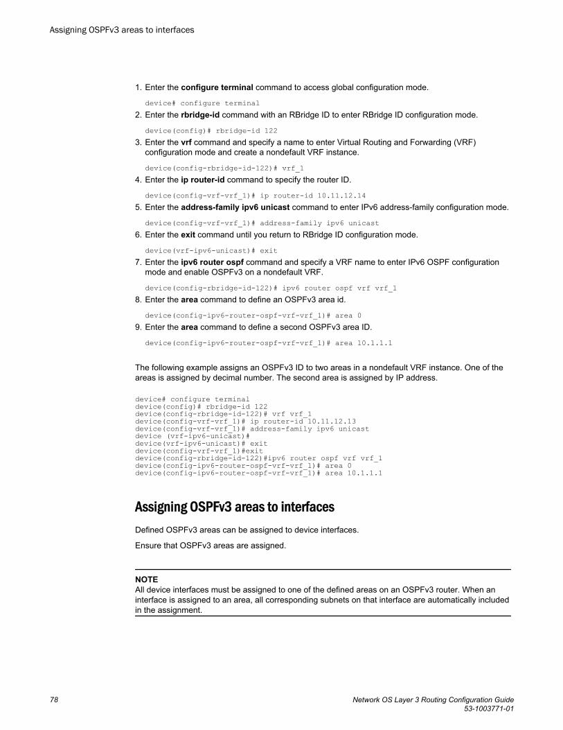
1. Enter the configure terminal command to access global configuration mode.
device# configure terminal2. Enter the rbridge-id command with an RBridge ID to enter RBridge ID configuration mode.
device(config)# rbridge-id 1223. Enter the vrf command and specify a name to enter Virtual Routing and Forwarding (VRF)
configuration mode and create a nondefault VRF instance.
device(config-rbridge-id-122)# vrf_14. Enter the ip router-id command to specify the router ID.
device(config-vrf-vrf_1)# ip router-id 10.11.12.145. Enter the address-family ipv6 unicast command to enter IPv6 address-family configuration mode.
device(config-vrf-vrf_1)# address-family ipv6 unicast6. Enter the exit command until you return to RBridge ID configuration mode.
device(vrf-ipv6-unicast)# exit7. Enter the ipv6 router ospf command and specify a VRF name to enter IPv6 OSPF configuration
mode and enable OSPFv3 on a nondefault VRF.
device(config-rbridge-id-122)# ipv6 router ospf vrf vrf_18. Enter the area command to define an OSPFv3 area id.
device(config-ipv6-router-ospf-vrf-vrf_1)# area 09. Enter the area command to define a second OSPFv3 area ID.
device(config-ipv6-router-ospf-vrf-vrf_1)# area 10.1.1.1
The following example assigns an OSPFv3 ID to two areas in a nondefault VRF instance. One of theareas is assigned by decimal number. The second area is assigned by IP address.
device# configure terminaldevice(config)# rbridge-id 122device(config-rbridge-id-122)# vrf vrf_1device(config-vrf-vrf_1)# ip router-id 10.11.12.13device(config-vrf-vrf_1)# address-family ipv6 unicast device (vrf-ipv6-unicast)#device(vrf-ipv6-unicast)# exitdevice(config-vrf-vrf_1)#exitdevice(config-rbridge-id-122)#ipv6 router ospf vrf vrf_1device(config-ipv6-router-ospf-vrf-vrf_1)# area 0device(config-ipv6-router-ospf-vrf-vrf_1)# area 10.1.1.1
Assigning OSPFv3 areas to interfacesDefined OSPFv3 areas can be assigned to device interfaces.
Ensure that OSPFv3 areas are assigned.
NOTEAll device interfaces must be assigned to one of the defined areas on an OSPFv3 router. When aninterface is assigned to an area, all corresponding subnets on that interface are automatically includedin the assignment.
Assigning OSPFv3 areas to interfaces
78 Network OS Layer 3 Routing Configuration Guide53-1003771-01
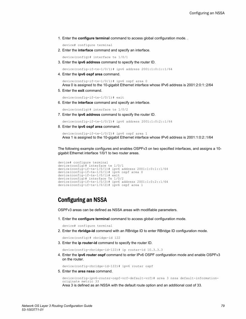
1. Enter the configure terminal command to access global configuration mode. .
device# configure terminal2. Enter the interface command and specify an interface.
device(config)# interface te 1/0/13. Enter the ipv6 address command to specify the router ID.
device(config-if-te-1/0/1)# ipv6 address 2001:1:0:1::1/644. Enter the ipv6 ospf area command.
device(config-if-te-1/0/1)# ipv6 ospf area 0Area 0 is assigned to the 10-gigabit Ethernet interface whose IPv6 address is 2001:2:0:1::2/64
5. Enter the exit command.
device(config-if-te-1/0/1)# exit6. Enter the interface command and specify an interface.
device(config)# interface te 1/0/27. Enter the ipv6 address command to specify the router ID.
device(config-if-te-1/0/2)# ipv6 address 2001:1:0:2::1/648. Enter the ipv6 ospf area command.
device(config-if-te-1/0/2)# ipv6 ospf area 1Area 1 is assigned to the 10-gigabit Ethernet interface whose IPv6 address is 2001:1:0:2::1/64
The following example configures and enables OSPFv3 on two specified interfaces, and assigns a 10-gigabit Ethernet interface 1/0/1 to two router areas.
device# configure terminaldevice(config)# interface te 1/0/1device(config-if-te-1/0/1)# ipv6 address 2001:1:0:1::1/64device(config-if-te-1/0/1)# ipv6 ospf area 0device(config-if-te-1/0/1)# exitdevice(config)# interface Te 1/0/2device(config-if-te-1/0/2)# ipv6 address 2001:1:0:2::1/64device(config-if-te-1/0/2)# ipv6 ospf area 1
Configuring an NSSAOSPFv3 areas can be defined as NSSA areas with modifiable parameters.
1. Enter the configure terminal command to access global configuration mode.
device# configure terminal2. Enter the rbridge-id command with an RBridge ID to enter RBridge ID configuration mode.
device(config)# rbridge-id 1223. Enter the ip router-id command to specify the router ID.
device(config-rbridge-id-122)# ip router-id 10.3.3.34. Enter the ipv6 router ospf command to enter IPv6 OSPF configuration mode and enable OSPFv3
on the router.
device(config-rbridge-id-122)# ipv6 router ospf5. Enter the area nssa command.
device(config-ipv6-router-ospf-vrf-default-vrf)# area 3 nssa default-information-originate metric 33Area 3 is defined as an NSSA with the default route option and an additional cost of 33.
Configuring an NSSA
Network OS Layer 3 Routing Configuration Guide 7953-1003771-01
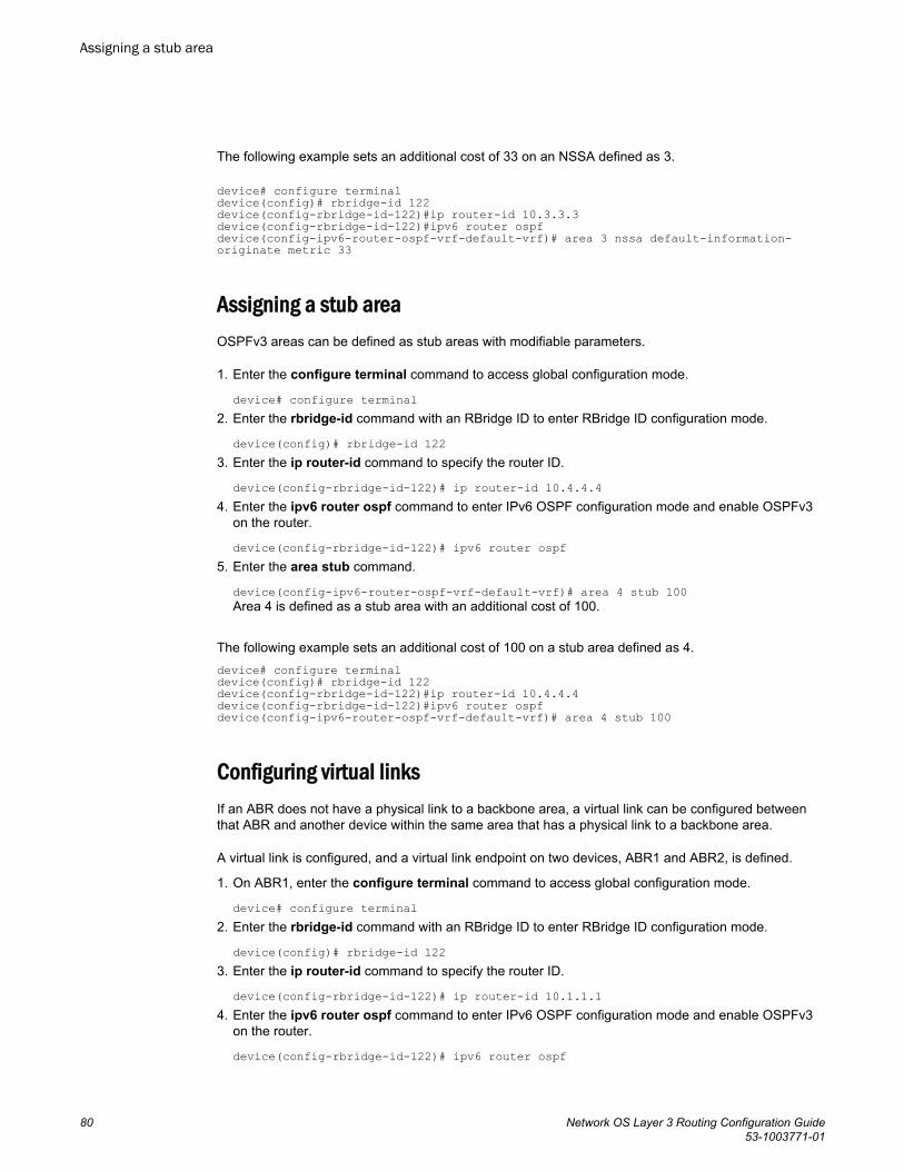
The following example sets an additional cost of 33 on an NSSA defined as 3.
device# configure terminaldevice(config)# rbridge-id 122device(config-rbridge-id-122)#ip router-id 10.3.3.3 device(config-rbridge-id-122)#ipv6 router ospf device(config-ipv6-router-ospf-vrf-default-vrf)# area 3 nssa default-information-originate metric 33
Assigning a stub areaOSPFv3 areas can be defined as stub areas with modifiable parameters.
1. Enter the configure terminal command to access global configuration mode.
device# configure terminal2. Enter the rbridge-id command with an RBridge ID to enter RBridge ID configuration mode.
device(config)# rbridge-id 1223. Enter the ip router-id command to specify the router ID.
device(config-rbridge-id-122)# ip router-id 10.4.4.44. Enter the ipv6 router ospf command to enter IPv6 OSPF configuration mode and enable OSPFv3
on the router.
device(config-rbridge-id-122)# ipv6 router ospf5. Enter the area stub command.
device(config-ipv6-router-ospf-vrf-default-vrf)# area 4 stub 100Area 4 is defined as a stub area with an additional cost of 100.
The following example sets an additional cost of 100 on a stub area defined as 4.device# configure terminaldevice(config)# rbridge-id 122device(config-rbridge-id-122)#ip router-id 10.4.4.4 device(config-rbridge-id-122)#ipv6 router ospf device(config-ipv6-router-ospf-vrf-default-vrf)# area 4 stub 100
Configuring virtual linksIf an ABR does not have a physical link to a backbone area, a virtual link can be configured betweenthat ABR and another device within the same area that has a physical link to a backbone area.
A virtual link is configured, and a virtual link endpoint on two devices, ABR1 and ABR2, is defined.
1. On ABR1, enter the configure terminal command to access global configuration mode.
device# configure terminal2. Enter the rbridge-id command with an RBridge ID to enter RBridge ID configuration mode.
device(config)# rbridge-id 1223. Enter the ip router-id command to specify the router ID.
device(config-rbridge-id-122)# ip router-id 10.1.1.14. Enter the ipv6 router ospf command to enter IPv6 OSPF configuration mode and enable OSPFv3
on the router.
device(config-rbridge-id-122)# ipv6 router ospf
Assigning a stub area
80 Network OS Layer 3 Routing Configuration Guide53-1003771-01
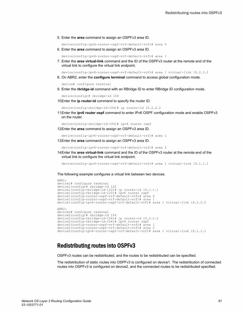
5. Enter the area command to assign an OSPFv3 area ID.
device(config-ipv6-router-ospf-vrf-default-vrf)# area 06. Enter the area command to assign an OSPFv3 area ID.
device(config-ipv6-router-ospf-vrf-default-vrf)# area 17. Enter the area virtual-link command and the ID of the OSPFv3 router at the remote end of the
virtual link to configure the virtual link endpoint.
device(config-ipv6-router-ospf-vrf-default-vrf)# area 1 virtual-link 10.2.2.28. On ABR2, enter the configure terminal command to access global configuration mode.
device# configure terminal9. Enter the rbridge-id command with an RBridge ID to enter RBridge ID configuration mode.
device(config)# rbridge-id 10410.Enter the ip router-id command to specify the router ID.
device(config-rbridge-id-104)# ip router-id 10.2.2.211.Enter the ipv6 router ospf command to enter IPv6 OSPF configuration mode and enable OSPFv3
on the router.
device(config-rbridge-id-104)# ipv6 router ospf12.Enter the area command to assign an OSPFv3 area ID.
device(config-ipv6-router-ospf-vrf-default-vrf)# area 113.Enter the area command to assign an OSPFv3 area ID.
device(config-ipv6-router-ospf-vrf-default-vrf)# area 214.Enter the area virtual-link command and the ID of the OSPFv3 router at the remote end of the
virtual link to configure the virtual link endpoint.
device(config-ipv6-router-ospf-vrf-default-vrf)# area 1 virtual-link 10.1.1.1
The following example configures a virtual link between two devices.ABR1:device1# configure terminaldevice1(config)# rbridge-id 122device1(config-rbridge-id-122)# ip router-id 10.1.1.1device1(config-rbridge-id-122)# ipv6 router ospfdevice1(config-router-ospf-vrf-default-vrf)# area 0device1(config-router-ospf-vrf-default-vrf)# area 1device1(config-ipv6-router-ospf-vrf-default-vrf)# area 1 virtual-link 10.2.2.2ABR2:device2# configure terminaldevice2(config)# rbridge-id 104device2(config-rbridge-id-104)# ip router-id 10.2.2.2device2(config-rbridge-id-104)# ipv6 router ospfdevice2(config-router-ospf-vrf-default-vrf)# area 1device2(config-router-ospf-vrf-default-vrf)# area 2device2(config-ipv6-router-ospf-vrf-default-vrf)# area 1 virtual-link 10.1.1.1
Redistributing routes into OSPFv3OSPFv3 routes can be redistributed, and the routes to be redistributed can be specified.
The redistribution of static routes into OSPFv3 is configured on device1. The redistribution of connectedroutes into OSPFv3 is configured on device2, and the connected routes to be redistributed specified.
Redistributing routes into OSPFv3
Network OS Layer 3 Routing Configuration Guide 8153-1003771-01
1. On device1, enter the configure terminal command to access global configuration mode.
device# configure terminal2. Enter the rbridge-id command with an RBridge ID to enter RBridge ID configuration mode.
device(config)# rbridge-id 1223. Enter the ipv6 router ospf command to enter IPv6 OSPF configuration mode and enable OSPFv3
on the router.
device(config-rbridge-id-122)# ipv6 router ospf4. Enter the redistribute command with the static parameter to redistribute static routes.
device(config-ipv6-router-ospf-vrf-default-vrf)# redistribute static5. On device2, enter the configure terminal command to access global configuration mode.
device# configure terminal6. Enter the rbridge-id command with an RBridge ID to enter RBridge ID configuration mode.
device(config)# rbridge-id 1227. Enter the ipv6 router ospf command to enter IPv6 OSPF configuration mode and enable OSPFv3
on the router.
device(config-rbridge-id-122)# ipv6 router ospf8. Enter the redistribute command with the connected and route-map parameters to redistribute
connected routes and specify a route map.
device(config-ipv6-router-ospf-vrf-default-vrf)# redistribute connected route-map rmap1
The following example redistributes static routes into OSPFv3 on a device.
device# configure terminaldevice(config)# rbridge-id 122device(config-rbridge-id-122)# ipv6 router ospf device(config-ipv6-router-ospf-vrf-default-vrf)# redistribute static
The following example redistributes connected routes into OSPFv3 on a device and specifies a routemap.
device# configure terminaldevice(config)# rbridge-id 122device(config-rbridge-id-122)# ipv6 router ospf device(config-ipv6-router-ospf-vrf-default-vrf)# redistribute connected route-map rmap1
Modifying Shortest Path First timersThe Shortest Path First (SPF) delay and hold time can be modified.
1. Enter the configure terminal command to access global configuration mode.
device# configure terminal2. Enter the rbridge-id command with an RBridge ID to enter RBridge ID configuration mode..
device(config)# rbridge-id 122
Modifying Shortest Path First timers
82 Network OS Layer 3 Routing Configuration Guide53-1003771-01
3. Enter the ipv6 router ospf command to enter IPv6 OSPF configuration mode and enable OSPFv3globally.
device(config-rbridge-id-122)# ipv6 router ospf4. Enter the timers command with the spf parameter.
device(config-ipv6-router-ospf-vrf-default-vrf)# timers spf 10 20The SPF delay is changed to 10 seconds and the SPF hold time is changed to 20 seconds.
The following example changes the SPF delay and hold time.
device# configure terminaldevice(config)# rbridge-id 122device(config-rbridge-id-122)# ipv6 router ospf device(config-ipv6-router-ospf-vrf-default-vrf)# timers spf 10 20
Configuring the OSPFv3 LSA pacing intervalThe interval between OSPFv3 LSA refreshes can be modified.
1. Enter the configure terminal command to access global configuration mode.
device# configure terminal2. Enter the rbridge-id command with an RBridge ID t o enter RBridge ID configuration mode.
device(config)# rbridge-id 1223. Enter the ipv6 router ospf command to enter IPv6 OSPF configuration mode and enable OSPFv3
globally.
device(config-rbridge-id-122)# ipv6 router ospf4. Enter the timers command with the lsa-group-pacing parameter.
device(config-ipv6-router-ospf-vrf-default-vrf)# timers lsa-group-pacing 120The OSPFv3 LSA pacing interval is changed to two minutes (120 seconds).
5. Enter the no timers command with the lsa-group-pacing parameter.
device(config-ipv6-router-ospf-vrf-default-vrf)# no timers lsa-group-pacing The pacing interval is restored to its default value of 4 minutes (240 seconds).
The following example changes the interval between OSPFv3 LSA refreshes and then restores thepacing interval to its default value.
device# configure terminaldevice(config)# rbridge-id 122device(config-rbridge-id-122)# ipv6 router ospf device(config-ipv6-router-ospf-vrf-default-vrf)# timers lsa-group-pacing 120device(config-ipv6-router-ospf-vrf-default-vrf)# no timers lsa-group-pacing
Configuring default route originOSPFv3 default routes can be created and advertised.
1. Enter the configure terminal command to access global configuration mode.
device# configure terminal2. Enter the rbridge-id command with an RBridge ID to enter RBridge ID configuration mode.
device(config)# rbridge-id 122
Configuring the OSPFv3 LSA pacing interval
Network OS Layer 3 Routing Configuration Guide 8353-1003771-01
3. Enter the ipv6 router ospf command to enter IPv6 OSPF configuration mode and enable OSPFv3globally.
device(config-rbridge-id-122)# ipv6 router ospf4. Enter the default-information-originate command with the always, metric, and metric-type
parameters.
device(config-ipv6-router-ospf-vrf-default-vrf)# default-information-originate always metric 2 metric-type type1A default type 1 external route with a metric of 2 is created and advertised.
The following example creates and advertises a default route with a metric of 2 and a type 1 externalroute.
device# configure terminaldevice(config)# rbridge-id 122device(config-rbridge-id-122)# ipv6 router ospf device(config-ipv6-router-ospf-vrf-default-vrf)# default-information-originate always metric 2 metric-type type1
Disabling and re-enabling OSPFv3 event loggingOSPFv3 event logging, such as neighbor state changes and database overflow conditions, can bedisabled and re-enabled.
1. Enter the configure terminal command to access global configuration mode.
device# configure terminal2. Enter the rbridge-id command with an RBridge ID to enter RBridge ID configuration mode.
device(config)# rbridge-id 1223. Enter the ipv6 router ospf command to enter IPv6 OSPF configuration mode and enable OSPFv3
globally.
device(config-rbridge-id-122)# ipv6 router ospf4. Enter the no log command to disable the logging of OSPFv3 events.
device(config-ipv6-router-ospf-vrf-default-vrf)# no log
The following example re-enables the logging of OSPFv3 events.
device# configure terminaldevice(config)# rbridge-id 122device(config-rbridge-id-122)# ipv6 router ospf device(config-ipv6-router-ospf-vrf-default-vrf)# log all
Configuring administrative distance based on route typeThe default administrative distances for intra-area routes, inter-area routes, and external routes can bealtered.
1. Enter the configure terminal command to access global configuration mode.
device# configure terminal2. Enter the rbridge-id command with an RBridge ID to enter RBridge ID configuration mode.
device(config)# rbridge-id 122
Disabling and re-enabling OSPFv3 event logging
84 Network OS Layer 3 Routing Configuration Guide53-1003771-01
3. Enter the ipv6 router ospf command to enter IPv6 OSPF configuration mode and enable OSPFv3globally.
device(config-rbridge-id-122)# ipv6 router ospf4. Enter the distance command with the intra-area parameter.
device(config-ipv6-router-ospf-vrf-default-vrf)# distance intra-area 80The administrative distance for intra-area routes is changed from the default to 80.
5. Enter the distance command with the inter-area parameter.
device(config-ipv6-router-ospf-vrf-default-vrf)# distance inter-area 90The administrative distance for inter-area routes is changed from the default to 90.
6. Enter the distance command with the external parameter.
device(config-ipv6-router-ospf-vrf-default-vrf)# distance external 100The administrative distance for external routes is changed from the default to 100.
The following example changes the default administrative distances for intra-area routes, inter-arearoutes, and external routes.
device# configure terminaldevice(config)# rbridge-id 122device(config-rbridge-id-122)# ipv6 router ospf device(config-ipv6-router-ospf-vrf-default-vrf)# distance intra-area 80device(config-ipv6-router-ospf-vrf-default-vrf)# distance inter-area 90device(config-ipv6-router-ospf-vrf-default-vrf)# distance external 100
Changing the reference bandwidth for the cost on OSPFv3The reference bandwidth for OSPFv3 can be altered, resulting in various costs.
1. Enter the configure terminal command to access global configuration mode.
device# configure terminal2. Enter the rbridge-id command with an RBridge ID to enter RBridge ID configuration mode.
device(config)# rbridge-id 1223. Enter the ipv6 router ospf command to enter IPv6 OSPF configuration mode and enable OSPFv3
globally.
device(config-rbridge-id-122)# ipv6 router ospf4. Enter the auto-cost reference-bandwidth command to change the reference bandwidth.
device(config-ipv6-router-ospf-vrf-default-vrf)# auto-cost reference-bandwidth 500
Changing the reference bandwidth for the cost on OSPFv3
Network OS Layer 3 Routing Configuration Guide 8553-1003771-01
The following example changes the auto-cost reference-bandwidth to 500.
device# configure terminaldevice(config)# rbridge-id 122device(config-rbridge-id-122)# ipv6 router ospf device(config-ipv6-router-ospf-vrf-default-vrf)# auto-cost reference-bandwidth 500The reference bandwidth specified in this example results in the following costs:
• 10-Mbps port cost = 500/10 = 50• 100-Mbps port cost = 500/100 = 5• 1000-Mbps port cost = 500/1000 = 0.5, which is rounded up to 1• 155-Mbps port cost = 500/155 = 3.23, which is rounded up to 4• 622-Mbps port cost = 500/622 = 0.80, which is rounded up to 1• 2488-Mbps port cost = 500/2488 = 0.20, which is rounded up to 1
The costs for 10-Mbps, 100-Mbps, and 155-Mbps ports change as a result of the changed referencebandwidth. Costs for higher-speed interfaces remain the same.
Setting all OSPFv3 interfaces to the passive stateAll OSPFv3 interfaces for a specified RBridge can be set as passive. This causes them to drop allOSPFv3 control packets.
1. Enter the configure terminal command to access global configuration mode.
device# configure terminal2. Enter the rbridge-id command with an RBridge ID to enter RBridge ID configuration mode.
device(config)# rbridge-id 1223. Enter the ipv6 router ospf command to enter IPv6 OSPF configuration mode and enable OSPFv3
globally.
device(config-rbridge-id-122)# ipv6 router ospf4. Enter the default-passive-interface command to mark all interfaces passive by default.
device(config-ipv6-router-ospf-vrf-default-vrf)# default-passive-interface
The following example sets all OSPFv3 interfaces for a specified RBridge as passive, causing them todrop all the OSPFv3 control packets.
device# configure terminaldevice(config)# rbridge-id 122device(config-rbridge-id-122)# ipv6 router ospf device(config-ipv6-router-ospf-vrf-default-vrf)# default-passive-interface
Disabling OSPFv3 graceful restart helperThe OSPFv3 graceful restart (GR) helper feature is enabled by default, and can be disabled on arouting device.
Setting all OSPFv3 interfaces to the passive state
86 Network OS Layer 3 Routing Configuration Guide53-1003771-01
1. Enter the configure terminal command to access global configuration mode.
device# configure terminal2. Enter the rbridge-id command with an RBridge ID to enter RBridge ID configuration mode.
device(config)# rbridge-id 1223. Enter the ipv6 router ospf command to enter OSPFv3 VRF router configuration mode and enable
OSPFv3 globally.
device(config-rbridge-id-122)# ipv6 router ospf4. Enter the no graceful-restart helper command to disable the GR helper feature.
device(config-ipv6-router-ospf-vrf-default-vrf)# no graceful-restart helper
The following example disables the GR helper feature.
device# configure terminaldevice(config)# rbridge-id 122device(config-rbridge-id-122)# ipv6 router ospf device(config-ipv6-router-ospf-vrf-default-vrf)# no graceful-restart helper
Re-enabling OSPFv3 graceful restart helperIf the OSPFv3 graceful restart (GR) helper feature has been disabled on a routing device, it can be re-enabled. GR helper mode can also be enabled with strict link-state advertisement (LSA) checking.
1. Enter the configure terminal command to access global configuration mode.
device# configure terminal2. Enter the rbridge-id command with an RBridge ID to enter RBridge ID configuration mode.
device(config)# rbridge-id 1223. Enter the ipv6 router ospf command to enter OSPFv3 VRF router configuration mode and enable
OSPFv3 globally.
device(config-rbridge-id-122)# ipv6 router ospf4. Enter the graceful-restart helper command and specify the strict-lsa-checking parameter to re-
enable the GR helper feature with strict LSA checking.
device(config-ipv6-router-ospf-vrf-default-vrf)# graceful-restart helper strict-lsa-checking
The following example re-enables the GR helper feature with strict LSA checking.
device# configure terminaldevice(config)# rbridge-id 122device(config-rbridge-id-122)# ipv6 router ospf device(config-ipv6-router-ospf-vrf-default-vrf)# graceful-restart helper strict-lsa-checking
Configuring the OSPFv3 max-metric router LSABy configuring the OSPFv3 max-metric router LSA feature you can enable OSPFv3 to advertise itslocally generated router LSAs with a maximum metric.
Re-enabling OSPFv3 graceful restart helper
Network OS Layer 3 Routing Configuration Guide 8753-1003771-01
1. Enter the configure terminal command to access global configuration mode.
device# configure terminal2. Enter the rbridge-id command with an RBridge ID to enter RBridge ID configuration mode.
device(config)# rbridge-id 1223. Enter the ip router-id command to specify the router ID.
device(config-rbridge-id-122)# ip router-id 10.11.12.134. Enter the ipv6 router ospf command to enter IPv6 OSPF configuration mode and enable OSPFv3
on the router.
device(config-rbridge-id-122)# ipv6 router ospf5. Enter the max-metric router-lsa command with the external-lsa keyword and specify a value to
configure the maximum metric value for all external type-5 and type-7 LSAs .
device(config-ipv6-router-ospf-vrf-default-vrf)# max-metric router-lsa external-lsa 1500
This example configures an OSPFv3 device to advertise a maximum metric and sets the maximummetric value for all external type-5 and type-7 LSAs to 1500.
device# configuredevice(config)# rbridge-id 122device(config-rbridge-id-122)# ip router-id 10.11.12.13device(config-rbridge-id-122)# ipv6 router ospf device(config-ipv6-router-ospf-vrf-default-vrf)# max-metric router-lsa external-lsa 1500
Configuring IPsec on an OSPFv3 areaIP Security (IPsec) secures OSPFv3 communications by authenticating and encrypting each IP packetof a communication session. IPsec can be configured on an OSPF area.
NOTEWhen IPsec is configured for an area, the security policy is applied to all the interfaces in the area.
1. Enter configure terminal.
device# configure terminal2. Enter the rbridge-id command with an RBridge ID to enter RBridge ID configuration mode.
device(config)# rbridge-id 1223. Enter the ip router-id command to specify the router ID.
device(config-rbridge-id-122)# ip router-id 10.11.12.134. Enter the ipv6 router ospf command to enter IPv6 OSPF configuration mode and enable OSPFv3
on the router.
device(config-rbridge-id-122)# ipv6 router ospf5. Enter area authentication spi spi ah hmac-md5 key.
device(config-ipv6-router-ospf-vrf-default-vrf)# area 0 authentication spi 600 ah hmac-md5 key abcef12345678901234fedcba098765432109876Configures IPsec in OSPF area 0. The security parameter index (SPI) value is 600, and theauthentication header (AH) protocol is selected. Message Digest 5 (MD5) authentication on thearea is enabled.
Configuring IPsec on an OSPFv3 area
88 Network OS Layer 3 Routing Configuration Guide53-1003771-01
The following example enables AH and MD5 authentication for the OSPF area, setting a SPI value of600.
device# configure terminaldevice(config)# rbridge-id 122device(config-rbridge-id-122)# ip router-id 10.11.12.13device(config-rbridge-id-122)# ipv6 router ospfdevice(config-ipv6-router-ospf-vrf-default-vrf)# area 0 authentication spi 600 ah hmac-md5 key abcef12345678901234fedcba098765432109876
Configuring IPsec on an OSPFv3 interfaceIP Security (IPsec) secures OSPFv3 communications by authenticating and encrypting each IP packetof a communication session. Specific OSPFv3 interfaces can be secured using IPsec.
Ensure that OSPFv3 areas are assigned. For IPsec to work, the IPsec configuration must be the sameon all the routers to which an interface connects.
NOTEAll device interfaces must be assigned to one of the defined areas on an OSPFv3 router. When aninterface is assigned to an area, all corresponding subnets on that interface are automatically includedin the assignment.
1. Enter the configure terminal command to access global configuration mode.
device# configure terminal2. Enter the interface command and specify an interface.
device(config)# interface te 1/0/13. Enter the ipv6 ospf area command to assign a specified area to the interface.
device(config-if-te-1/0/1)# ipv6 ospf area 04. Enter ipv6 ospf authentication spi spi esp null hmac-sha1 key.
device(config-if-te-1/0/1)# ipv6 ospf authentication spi 512 esp null hmac-sha1 key abcef12345678901234fedcba098765432109876
Configures IPsec on the specified interface. The SPI value is 512, and the Encapsulating SecurityPayload (ESP) protocol is selected. Secure Hash Algorithm 1 (SHA-1) authentication is enabled.
The following example enables ESP and SHA-1 on a specified OSPFv3 10-gigabit interface.
device# configure terminaldevice(config)# interface te 1/0/1device(config-if-te-1/0/1)# ipv6 ospf area 0device(config-if-te-1/0/1)# ipv6 ospf authentication spi 512 esp null hmac-sha1 key abcef12345678901234fedcba098765432109876
Configuring IPsec on OSPFv3 virtual linksIP Security (IPsec) can be configured for virtual links.
An OSPFv3 virtual link must be configured.
The virtual link IPsec security associations (SAs) and policies are added to all interfaces of the transitarea for the outbound direction. For the inbound direction, IPsec SAs and policies for virtual links areadded to the global database.
Configuring IPsec on an OSPFv3 interface
Network OS Layer 3 Routing Configuration Guide 8953-1003771-01
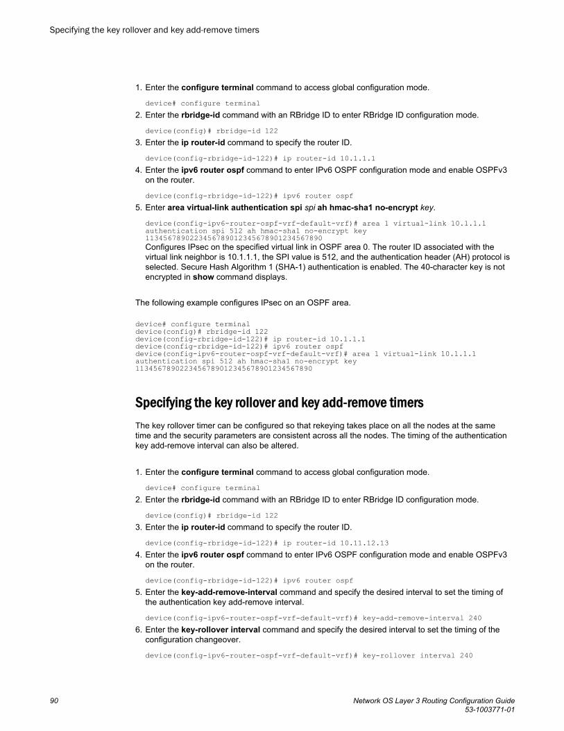
1. Enter the configure terminal command to access global configuration mode.
device# configure terminal2. Enter the rbridge-id command with an RBridge ID to enter RBridge ID configuration mode.
device(config)# rbridge-id 1223. Enter the ip router-id command to specify the router ID.
device(config-rbridge-id-122)# ip router-id 10.1.1.14. Enter the ipv6 router ospf command to enter IPv6 OSPF configuration mode and enable OSPFv3
on the router.
device(config-rbridge-id-122)# ipv6 router ospf5. Enter area virtual-link authentication spi spi ah hmac-sha1 no-encrypt key.
device(config-ipv6-router-ospf-vrf-default-vrf)# area 1 virtual-link 10.1.1.1 authentication spi 512 ah hmac-sha1 no-encrypt key 1134567890223456789012345678901234567890Configures IPsec on the specified virtual link in OSPF area 0. The router ID associated with thevirtual link neighbor is 10.1.1.1, the SPI value is 512, and the authentication header (AH) protocol isselected. Secure Hash Algorithm 1 (SHA-1) authentication is enabled. The 40-character key is notencrypted in show command displays.
The following example configures IPsec on an OSPF area.
device# configure terminaldevice(config)# rbridge-id 122device(config-rbridge-id-122)# ip router-id 10.1.1.1device(config-rbridge-id-122)# ipv6 router ospfdevice(config-ipv6-router-ospf-vrf-default-vrf)# area 1 virtual-link 10.1.1.1 authentication spi 512 ah hmac-sha1 no-encrypt key 1134567890223456789012345678901234567890
Specifying the key rollover and key add-remove timersThe key rollover timer can be configured so that rekeying takes place on all the nodes at the sametime and the security parameters are consistent across all the nodes. The timing of the authenticationkey add-remove interval can also be altered.
1. Enter the configure terminal command to access global configuration mode.
device# configure terminal2. Enter the rbridge-id command with an RBridge ID to enter RBridge ID configuration mode.
device(config)# rbridge-id 1223. Enter the ip router-id command to specify the router ID.
device(config-rbridge-id-122)# ip router-id 10.11.12.134. Enter the ipv6 router ospf command to enter IPv6 OSPF configuration mode and enable OSPFv3
on the router.
device(config-rbridge-id-122)# ipv6 router ospf5. Enter the key-add-remove-interval command and specify the desired interval to set the timing of
the authentication key add-remove interval.
device(config-ipv6-router-ospf-vrf-default-vrf)# key-add-remove-interval 2406. Enter the key-rollover interval command and specify the desired interval to set the timing of the
configuration changeover.
device(config-ipv6-router-ospf-vrf-default-vrf)# key-rollover interval 240
Specifying the key rollover and key add-remove timers
90 Network OS Layer 3 Routing Configuration Guide53-1003771-01
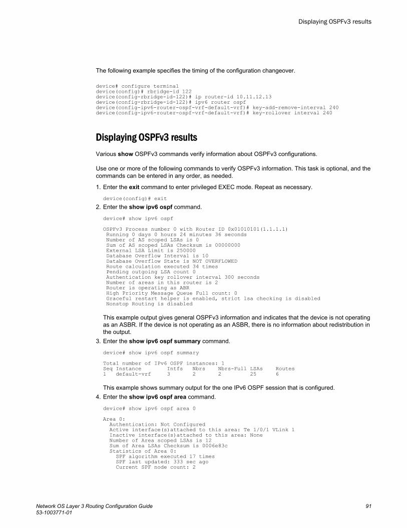
The following example specifies the timing of the configuration changeover.
device# configure terminaldevice(config)# rbridge-id 122device(config-rbridge-id-122)# ip router-id 10.11.12.13device(config-rbridge-id-122)# ipv6 router ospf device(config-ipv6-router-ospf-vrf-default-vrf)# key-add-remove-interval 240device(config-ipv6-router-ospf-vrf-default-vrf)# key-rollover interval 240
Displaying OSPFv3 resultsVarious show OSPFv3 commands verify information about OSPFv3 configurations.
Use one or more of the following commands to verify OSPFv3 information. This task is optional, and thecommands can be entered in any order, as needed.
1. Enter the exit command to enter privileged EXEC mode. Repeat as necessary.
device(config)# exit2. Enter the show ipv6 ospf command.
device# show ipv6 ospfOSPFv3 Process number 0 with Router ID 0x01010101(1.1.1.1) Running 0 days 0 hours 24 minutes 36 seconds Number of AS scoped LSAs is 0 Sum of AS scoped LSAs Checksum is 00000000 External LSA Limit is 250000 Database Overflow Interval is 10 Database Overflow State is NOT OVERFLOWED Route calculation executed 34 times Pending outgoing LSA count 0 Authentication key rollover interval 300 seconds Number of areas in this router is 2 Router is operating as ABR High Priority Message Queue Full count: 0 Graceful restart helper is enabled, strict lsa checking is disabled Nonstop Routing is disabled
This example output gives general OSPFv3 information and indicates that the device is not operatingas an ASBR. If the device is not operating as an ASBR, there is no information about redistribution inthe output.
3. Enter the show ipv6 ospf summary command.
device# show ipv6 ospf summary Total number of IPv6 OSPF instances: 1Seq Instance Intfs Nbrs Nbrs-Full LSAs Routes 1 default-vrf 3 2 2 25 6 This example shows summary output for the one IPv6 OSPF session that is configured.
4. Enter the show ipv6 ospf area command.
device# show ipv6 ospf area 0Area 0: Authentication: Not Configured Active interface(s)attached to this area: Te 1/0/1 VLink 1 Inactive interface(s)attached to this area: None Number of Area scoped LSAs is 12 Sum of Area LSAs Checksum is 0006e83c Statistics of Area 0: SPF algorithm executed 17 times SPF last updated: 333 sec ago Current SPF node count: 2
Displaying OSPFv3 results
Network OS Layer 3 Routing Configuration Guide 9153-1003771-01
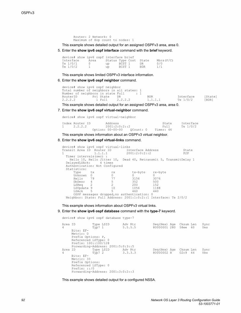
Router: 2 Network: 0 Maximum of Hop count to nodes: 1This example shows detailed output for an assigned OSPFv3 area, area 0.
5. Enter the show ipv6 ospf interface command with the brief keyword.
device# show ipv6 ospf interface brief Interface Area Status Type Cost State Nbrs(F/C)Te 1/0/1 0 up BCST 1 DR 0/0Te 1/0/2 1 up BCST 1 BDR 1/1
This example shows limited OSPFv3 interface information.6. Enter the show ipv6 ospf neighbor command.
device# show ipv6 ospf neighbor Total number of neighbors in all states: 1Number of neighbors in state Full : 1RouterID Pri State DR BDR Interface [State]2.2.2.2 1 Full 2.2.2.2 1.1.1.1 Te 1/0/2 [BDR]This example shows detailed output for an assigned OSPFv3 area, area 0.
7. Enter the show ipv6 ospf virtual-neighbor command.
device# show ipv6 ospf virtual-neighbor Index Router ID Address State Interface1 2.2.2.2 2001:2:0:2::2 Full Te 1/0/2 Option: 00-00-00 QCount: 0 Timer: 46This example shows information about an OSPFv3 virtual neighbor.
8. Enter the show ipv6 ospf virtual-links command.
device# show ipv6 ospf virtual-links Transit Area ID Router ID Interface Address State1 1.1.1.1 2001:2:0:2::2 P2P Timer intervals(sec) : Hello 10, Hello Jitter 10, Dead 40, Retransmit 5, TransmitDelay 1 DelayedLSAck: 4 times Authentication: Not Configured Statistics: Type tx rx tx-byte rx-byte Unknown 0 0 0 0 Hello 79 77 3156 3076 DbDesc 4 5 352 500 LSReq 2 2 200 152 LSUpdate 9 10 1056 1188 LSAck 5 5 460 440 OSPF messages dropped,no authentication: 0 Neighbor: State: Full Address: 2001:1:0:2::1 Interface: Te 2/0/2
This example shows information about OSPFv3 virtual links.9. Enter the show ipv6 ospf database command with the type-7 keyword.
device# show ipv6 ospf database type-7 Area ID Type LSID Adv Rtr Seq(Hex) Age Cksum Len Sync4 Typ7 1 5.5.5.5 80000001 280 58ee 60 Yes Bits: EF- Metric: 0 Prefix Options: P, Referenced LSType: 0 Prefix: 100::100/128 Forwarding-Address: 2001:5:0:3::5Area ID Type LSID Adv Rtr Seq(Hex) Age Cksum Len Sync4 Typ7 2 3.3.3.3 80000002 8 02c9 44 Yes Bits: EF- Metric: 33 Prefix Options: Referenced LSType: 0 Prefix: ::/0 Forwarding-Address: 2001:3:0:2::3
This example shows detailed output for a configured NSSA.
OSPFv3
92 Network OS Layer 3 Routing Configuration Guide53-1003771-01

10.Enter the show ipv6 ospf routes command.
device# show ipv6 ospf routes Destination Cost E2Cost Tag Flags DisE2 ::/0 1 33 0 00000027 110Next_Hop_Router Outgoing_Interface Adv_Router 2001:3:0:2::3 Te 4/0/2 3.3.3.3 Destination Cost E2Cost Tag Flags DisE2 100::100/128 1 0 0 0000000b 110Next_Hop_Router Outgoing_Interface Adv_Router 2001:5:0:3::5 Te 4/0/3 5.5.5.5
This example shows output for OSPFv3 routes.11.Enter the show ipv6 ospf database as-external command.
device# show ipv6 ospf database as-external Area ID Type LSID Adv Rtr Seq(Hex) Age Cksum Len SyncN/A Extn 106 6.6.6.6 80000001 533 7993 36 Yes Bits: E-- Metric: 0 Prefix Options: Referenced LSType: 0 Prefix: 4001::/64Area ID Type LSID Adv Rtr Seq(Hex) Age Cksum Len SyncN/A Extn 105 6.6.6.6 80000001 533 d230 44 Yes Bits: E-- Metric: 0 Prefix Options: Referenced LSType: 0 Prefix: 2::2/128This example shows information about external LSAs.
12.Enter the show ipv6 ospf database command.
device# show ipv6 ospf databaseLSA Key - Rtr:Router Net:Network Inap:InterPrefix Inar:InterRouter Extn:ASExternal Grp:GroupMembership Typ7:Type7 Link:Link Iap:IntraPrefix Grc:GraceArea ID Type LSID Adv Rtr Seq(Hex) Age Cksum Len Sync0 Link 145 6.6.6.6 80000002 1036 0432 56 Yes0 Link 7 1.1.1.1 80000002 595 b6b2 56 Yes0 Rtr 0 6.6.6.6 80000004 560 d1f4 40 Yes0 Rtr 0 1.1.1.1 80000004 1756 ce98 40 Yes0 Net 145 6.6.6.6 80000002 560 c899 32 Yes0 Iap 4350 6.6.6.6 80000002 560 903a 44 Yes1 Rtr 0 1.1.1.1 80000003 1756 0c20 24 YesN/A Extn 106 6.6.6.6 80000002 560 7794 36 YesN/A Extn 108 6.6.6.6 80000001 1678 9888 36 Yes
This example shows information about different OSPFv3 LSAs.13.Enter the show ipv6 ospf spf command with the tree keyword.
device# show ipv6 ospf spf tree SPF tree for Area 0 +- 1.1.1.1 cost 0 +- 6.6.6.6:145 cost 1 +- 6.6.6.6:0 cost 1 SPF tree for Area 1 +- 1.1.1.1 cost 0This example shows information about the SPF table for Area 4.
14.Enter the show ipv6 ospf spf command with the table keyword.
device# show ipv6 ospf spf tableSPF table for Area 4 Destination Bits Options Cost Nexthop InterfaceR 3.3.3.3 ---EB V6---NR-- 1 fe80::227:f8ff:feca:bbb8 Te 4/0/2R 5.5.5.5 ---E- V6---NR-- 1 fe80::205:33ff:fee5:4eda Te 4/0/3
OSPFv3
Network OS Layer 3 Routing Configuration Guide 9353-1003771-01
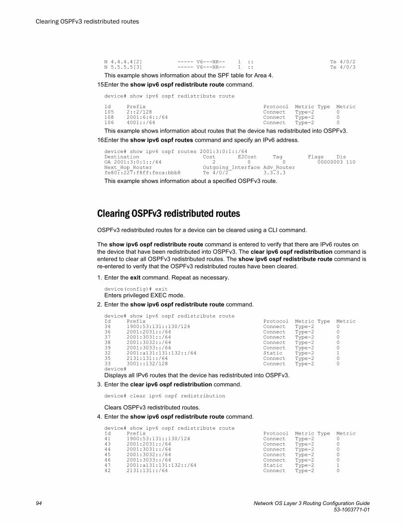
N 4.4.4.4[2] ----- V6---NR-- 1 :: Te 4/0/2N 5.5.5.5[3] ----- V6---NR-- 1 :: Te 4/0/3This example shows information about the SPF table for Area 4.
15.Enter the show ipv6 ospf redistribute route command.
device# show ipv6 ospf redistribute routeId Prefix Protocol Metric Type Metric105 2::2/128 Connect Type-2 0108 2001:6:4::/64 Connect Type-2 0106 4001::/64 Connect Type-2 0This example shows information about routes that the device has redistributed into OSPFv3.
16.Enter the show ipv6 ospf routes command and specify an IPv6 address.
device# show ipv6 ospf routes 2001:3:0:1::/64Destination Cost E2Cost Tag Flags DisOA 2001:3:0:1::/64 2 0 0 00000003 110Next_Hop_Router Outgoing_Interface Adv_Router fe80::227:f8ff:feca:bbb8 Te 4/0/2 3.3.3.3 This example shows information about a specified OSPFv3 route.
Clearing OSPFv3 redistributed routesOSPFv3 redistributed routes for a device can be cleared using a CLI command.
The show ipv6 ospf redistribute route command is entered to verify that there are IPv6 routes onthe device that have been redistributed into OSPFv3. The clear ipv6 ospf redistribution command isentered to clear all OSPFv3 redistributed routes. The show ipv6 ospf redistribute route command isre-entered to verify that the OSPFv3 redistributed routes have been cleared.
1. Enter the exit command. Repeat as necessary.
device(config)# exitEnters privileged EXEC mode.
2. Enter the show ipv6 ospf redistribute route command.
device# show ipv6 ospf redistribute routeId Prefix Protocol Metric Type Metric34 1900:53:131::130/124 Connect Type-2 036 2001:2031::/64 Connect Type-2 037 2001:3031::/64 Connect Type-2 038 2001:3032::/64 Connect Type-2 039 2001:3033::/64 Connect Type-2 032 2001:a131:131:132::/64 Static Type-2 135 2131:131::/64 Connect Type-2 033 3001::132/128 Connect Type-2 0device#Displays all IPv6 routes that the device has redistributed into OSPFv3.
3. Enter the clear ipv6 ospf redistribution command.
device# clear ipv6 ospf redistribution
Clears OSPFv3 redistributed routes.4. Enter the show ipv6 ospf redistribute route command.
device# show ipv6 ospf redistribute route Id Prefix Protocol Metric Type Metric41 1900:53:131::130/124 Connect Type-2 043 2001:2031::/64 Connect Type-2 044 2001:3031::/64 Connect Type-2 045 2001:3032::/64 Connect Type-2 046 2001:3033::/64 Connect Type-2 047 2001:a131:131:132::/64 Static Type-2 142 2131:131::/64 Connect Type-2 0
Clearing OSPFv3 redistributed routes
94 Network OS Layer 3 Routing Configuration Guide53-1003771-01
40 3001::132/128 Connect Type-2 0device#
Displays all IPv6 routes that the device has redistributed into OSPFv3.
The following example clears OSPFv3 redistributed routes for a device and verifies that the OSPFv3redistributed routes have been cleared:
device(config-ipv6-router-ospf-vrf)# exitdevice(config-rbridge-id-122)# exitdevice(config)# exitdevice# show ipv6 ospf redistribute routedevice# clear ipv6 ospf redistributiondevice# show ipv6 ospf redistribute route
OSPFv3
Network OS Layer 3 Routing Configuration Guide 9553-1003771-01

Clearing OSPFv3 redistributed routes
96 Network OS Layer 3 Routing Configuration Guide53-1003771-01
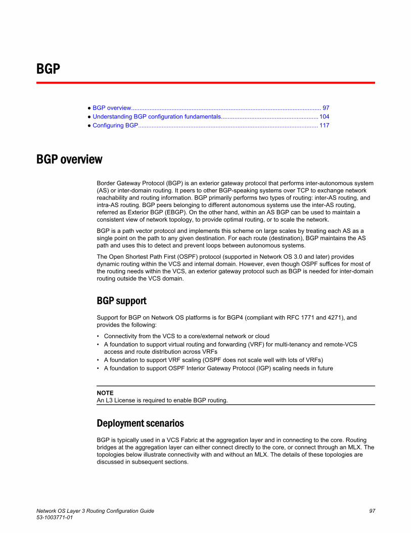
BGP
● BGP overview................................................................................................................. 97● Understanding BGP configuration fundamentals.......................................................... 104● Configuring BGP........................................................................................................... 117
BGP overviewBorder Gateway Protocol (BGP) is an exterior gateway protocol that performs inter-autonomous system(AS) or inter-domain routing. It peers to other BGP-speaking systems over TCP to exchange networkreachability and routing information. BGP primarily performs two types of routing: inter-AS routing, andintra-AS routing. BGP peers belonging to different autonomous systems use the inter-AS routing,referred as Exterior BGP (EBGP). On the other hand, within an AS BGP can be used to maintain aconsistent view of network topology, to provide optimal routing, or to scale the network.
BGP is a path vector protocol and implements this scheme on large scales by treating each AS as asingle point on the path to any given destination. For each route (destination), BGP maintains the ASpath and uses this to detect and prevent loops between autonomous systems.
The Open Shortest Path First (OSPF) protocol (supported in Network OS 3.0 and later) providesdynamic routing within the VCS and internal domain. However, even though OSPF suffices for most ofthe routing needs within the VCS, an exterior gateway protocol such as BGP is needed for inter-domainrouting outside the VCS domain.
BGP supportSupport for BGP on Network OS platforms is for BGP4 (compliant with RFC 1771 and 4271), andprovides the following:
• Connectivity from the VCS to a core/external network or cloud• A foundation to support virtual routing and forwarding (VRF) for multi-tenancy and remote-VCS
access and route distribution across VRFs• A foundation to support VRF scaling (OSPF does not scale well with lots of VRFs)• A foundation to support OSPF Interior Gateway Protocol (IGP) scaling needs in future
NOTEAn L3 License is required to enable BGP routing.
Deployment scenariosBGP is typically used in a VCS Fabric at the aggregation layer and in connecting to the core. Routingbridges at the aggregation layer can either connect directly to the core, or connect through an MLX. Thetopologies below illustrate connectivity with and without an MLX. The details of these topologies arediscussed in subsequent sections.
Network OS Layer 3 Routing Configuration Guide 9753-1003771-01
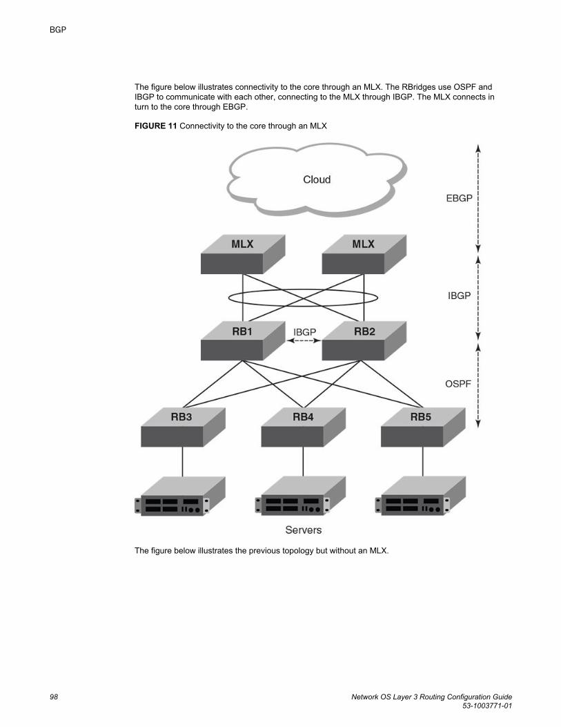
The figure below illustrates connectivity to the core through an MLX. The RBridges use OSPF andIBGP to communicate with each other, connecting to the MLX through IBGP. The MLX connects inturn to the core through EBGP.
FIGURE 11 Connectivity to the core through an MLX
The figure below illustrates the previous topology but without an MLX.
BGP
98 Network OS Layer 3 Routing Configuration Guide53-1003771-01
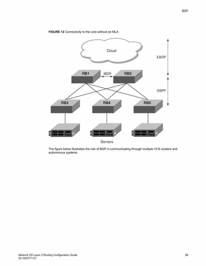
FIGURE 12 Connectivity to the core without an MLX
The figure below illustrates the role of BGP in communicating through multiple VCS clusters andautonomous systems.
BGP
Network OS Layer 3 Routing Configuration Guide 9953-1003771-01
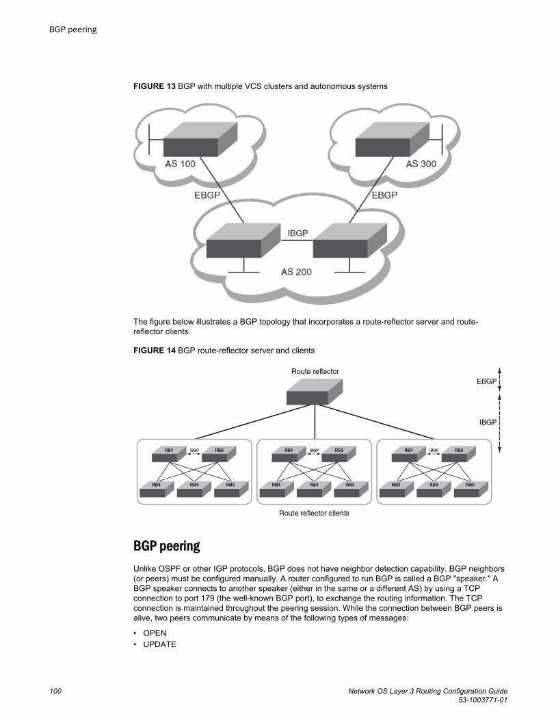
FIGURE 13 BGP with multiple VCS clusters and autonomous systems
The figure below illustrates a BGP topology that incorporates a route-reflector server and route-reflector clients.
FIGURE 14 BGP route-reflector server and clients
BGP peeringUnlike OSPF or other IGP protocols, BGP does not have neighbor detection capability. BGP neighbors(or peers) must be configured manually. A router configured to run BGP is called a BGP "speaker." ABGP speaker connects to another speaker (either in the same or a different AS) by using a TCPconnection to port 179 (the well-known BGP port), to exchange the routing information. The TCPconnection is maintained throughout the peering session. While the connection between BGP peers isalive, two peers communicate by means of the following types of messages:
• OPEN• UPDATE
BGP peering
100 Network OS Layer 3 Routing Configuration Guide53-1003771-01
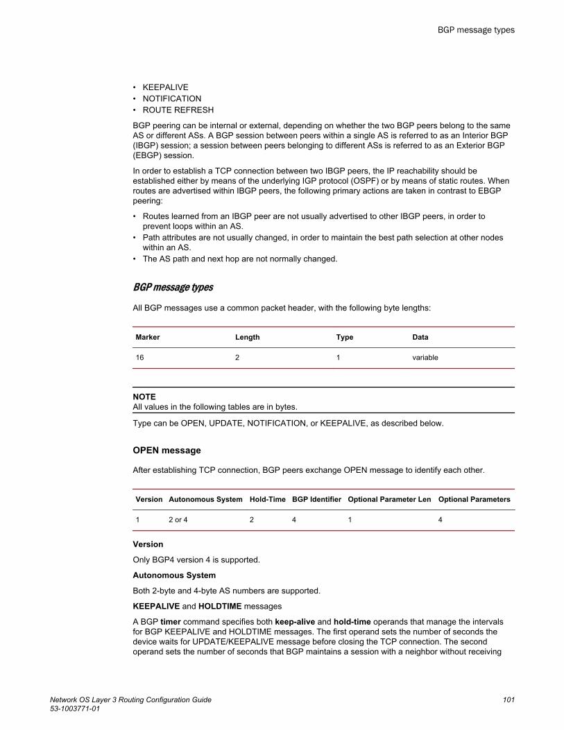
• KEEPALIVE• NOTIFICATION• ROUTE REFRESH
BGP peering can be internal or external, depending on whether the two BGP peers belong to the sameAS or different ASs. A BGP session between peers within a single AS is referred to as an Interior BGP(IBGP) session; a session between peers belonging to different ASs is referred to as an Exterior BGP(EBGP) session.
In order to establish a TCP connection between two IBGP peers, the IP reachability should beestablished either by means of the underlying IGP protocol (OSPF) or by means of static routes. Whenroutes are advertised within IBGP peers, the following primary actions are taken in contrast to EBGPpeering:
• Routes learned from an IBGP peer are not usually advertised to other IBGP peers, in order toprevent loops within an AS.
• Path attributes are not usually changed, in order to maintain the best path selection at other nodeswithin an AS.
• The AS path and next hop are not normally changed.
BGP message types
All BGP messages use a common packet header, with the following byte lengths:
Marker Length Type Data
16 2 1 variable
NOTEAll values in the following tables are in bytes.
Type can be OPEN, UPDATE, NOTIFICATION, or KEEPALIVE, as described below.
OPEN message
After establishing TCP connection, BGP peers exchange OPEN message to identify each other.
Version Autonomous System Hold-Time BGP Identifier Optional Parameter Len Optional Parameters
1 2 or 4 2 4 1 4
Version
Only BGP4 version 4 is supported.
Autonomous System
Both 2-byte and 4-byte AS numbers are supported.
KEEPALIVE and HOLDTIME messages
A BGP timer command specifies both keep-alive and hold-time operands that manage the intervalsfor BGP KEEPALIVE and HOLDTIME messages. The first operand sets the number of seconds thedevice waits for UPDATE/KEEPALIVE message before closing the TCP connection. The secondoperand sets the number of seconds that BGP maintains a session with a neighbor without receiving
BGP message types
Network OS Layer 3 Routing Configuration Guide 10153-1003771-01
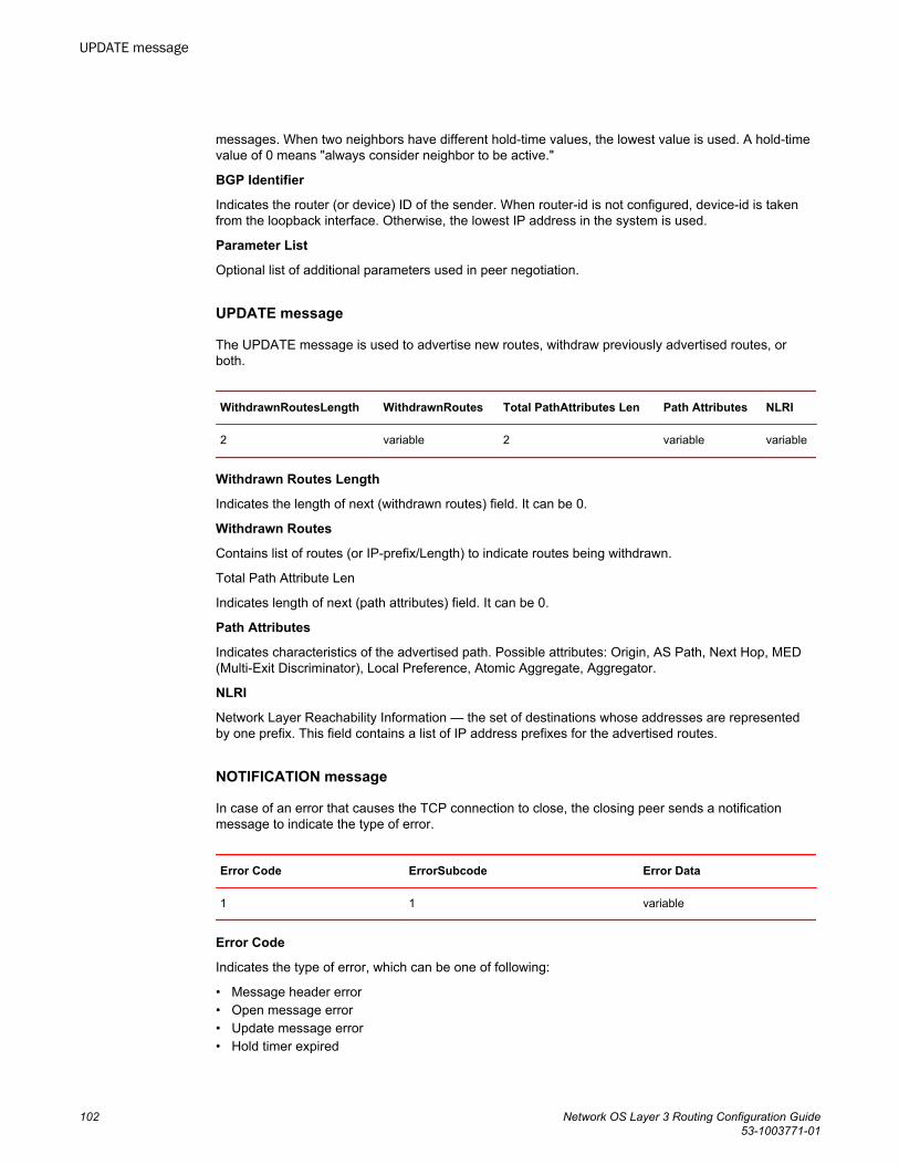
messages. When two neighbors have different hold-time values, the lowest value is used. A hold-timevalue of 0 means "always consider neighbor to be active."
BGP Identifier
Indicates the router (or device) ID of the sender. When router-id is not configured, device-id is takenfrom the loopback interface. Otherwise, the lowest IP address in the system is used.
Parameter List
Optional list of additional parameters used in peer negotiation.
UPDATE message
The UPDATE message is used to advertise new routes, withdraw previously advertised routes, orboth.
WithdrawnRoutesLength WithdrawnRoutes Total PathAttributes Len Path Attributes NLRI
2 variable 2 variable variable
Withdrawn Routes Length
Indicates the length of next (withdrawn routes) field. It can be 0.
Withdrawn Routes
Contains list of routes (or IP-prefix/Length) to indicate routes being withdrawn.
Total Path Attribute Len
Indicates length of next (path attributes) field. It can be 0.
Path Attributes
Indicates characteristics of the advertised path. Possible attributes: Origin, AS Path, Next Hop, MED(Multi-Exit Discriminator), Local Preference, Atomic Aggregate, Aggregator.
NLRI
Network Layer Reachability Information — the set of destinations whose addresses are representedby one prefix. This field contains a list of IP address prefixes for the advertised routes.
NOTIFICATION message
In case of an error that causes the TCP connection to close, the closing peer sends a notificationmessage to indicate the type of error.
Error Code ErrorSubcode Error Data
1 1 variable
Error Code
Indicates the type of error, which can be one of following:
• Message header error• Open message error• Update message error• Hold timer expired
UPDATE message
102 Network OS Layer 3 Routing Configuration Guide53-1003771-01
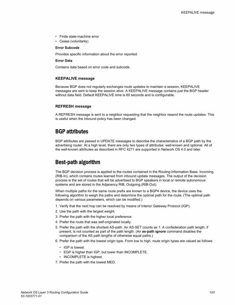
• Finite state-machine error• Cease (voluntarily)
Error Subcode
Provides specific information about the error reported.
Error Data
Contains data based on error code and subcode.
KEEPALIVE message
Because BGP does not regularly exchanges route updates to maintain a session, KEEPALIVEmessages are sent to keep the session alive. A KEEPALIVE message contains just the BGP headerwithout data field. Default KEEPALIVE time is 60 seconds and is configurable.
REFRESH message
A REFRESH message is sent to a neighbor requesting that the neighbor resend the route updates. Thisis useful when the inbound policy has been changed.
BGP attributesBGP attributes are passed in UPDATE messages to describe the characteristics of a BGP path by theadvertising router. At a high level, there are only two types of attributes: well-known and optional. All ofthe well-known attributes as described in RFC 4271 are supported in Network OS 4.0 and later.
Best-path algorithmThe BGP decision process is applied to the routes contained in the Routing Information Base, Incoming(RIB-In), which contains routes learned from inbound update messages. The output of the decisionprocess is the set of routes that will be advertised to BGP speakers in local or remote autonomoussystems and are stored in the Adjacency RIB, Outgoing (RIB-Out).
When multiple paths for the same route prefix are known to a BGP4 device, the device uses thefollowing algorithm to weigh the paths and determine the optimal path for the route. (The optimal pathdepends on various parameters, which can be modified.)
1. Verify that the next hop can be resolved by means of Interior Gateway Protocol (IGP).2. Use the path with the largest weight.3. Prefer the path with the higher local preference.4. Prefer the route that was self-originated locally.5. Prefer the path with the shortest AS-path. An AS-SET counts as 1. A confederation path length, if
present, is not counted as part of the path length. (An as-path ignore command disables thecomparison of the AS path lengths of otherwise equal paths.)
6. Prefer the path with the lowest origin type. From low to high, route origin types are valued as follows:
• IGP is lowest.• EGP is higher than IGP, but lower than INCOMPLETE.• INCOMPLETE is highest.
7. Prefer the path with the lowest MED.
KEEPALIVE message
Network OS Layer 3 Routing Configuration Guide 10353-1003771-01
The device compares the MEDs of two otherwise equivalent paths if and only if the routes werelearned from the same neighboring AS. This behavior is called deterministic MED. DeterministicMED is always enabled and cannot be disabled.
To ensure that the MEDs are always compared, regardless of the AS information in the paths, thealways-compare-med command can be used. This option is disabled by default.
The med-missing-as-worst command can be used to make the device regard a BGP4 route with amissing MED attribute as the least-favorable path when the MEDs of the route paths are compared.
MED comparison is not performed for internal routes that originate within the local AS orconfederation, unless the compare-med-empty-aspath command is configured.
8. Prefer paths in the following order:
• Routes received through EBGP from a BGP4 neighbor outside of the confederation• Routes received through EBGP from a BGP4 device within the confederation or routes received
through IBGP.9. If all the comparisons above are equal, prefer the route with the lowest IGP metric to the BGP4 next
hop. This is the closest internal path inside the AS to reach the destination.10.If the internal paths also are the same and BGP4 load sharing is enabled, load-share among the
paths. Otherwise go to Step 11.
NOTEFor EBGP routes, load sharing applies only when the paths are from neighbors within the sameremote AS. EBGP paths from neighbors in different ASs are not compared, unless multipath multi-as is enabled.
11.If compare-routerid is enabled, prefer the path that comes from the BGP4 device with the lowestdevice ID. If a path contains originator ID attributes, then the originator ID is substituted for therouter ID in the decision.
12.Prefer the path with the minimum cluster-list length.13.Prefer the route that comes from the lowest BGP4 neighbor address.
BGP limitations and considerationsThe following limitations and considerations apply to BGP support on Network OS platforms:
• There is no backward compatibility. In case of a downgrade, BGP configurations are lost.• There is no support for nonstop routing.• RASLogs are generated when a BGP session begins.• RASTRACE logs are available with module ID "261 BGP".• BGP logs are generated with module ID “BGP-1002”.
Understanding BGP configuration fundamentalsThis section provides an overview of the configuration considerations and basic steps required toenable BGP functionality. Examples are provided in Configuring BGP on page 117.
Similar to other Layer 3 protocols in Network OS, BGP is supported only in the VCS mode ofoperation. Each RBridge in a VCS fabric running BGP acts as an individual BGP device. BGP canform IBGP peering with other RBridges in the same VCS fabric running BGP.
BGP limitations and considerations
104 Network OS Layer 3 Routing Configuration Guide53-1003771-01
Configuring BGPTo enable BGP on an RBridge, enter Bridge ID configuration mode and issue the router bgpcommand:switch(config-rbridge-id-12)# router bgp There are two CLI modes for BGP:
• Global BGP• BGP Address-Family IPv4 Unicast
After issuing the router bgp command, you first enter into BGP configuration mode, where an address-family-specific configuration can be applied. In order to apply an IPv4 address-family-specificconfiguration, issue the address-family ipv4 unicast command.
To create a route map, enter the route-map command while in RBridge ID configuration mode. Thendeclare a route-map name by using a permit or deny statement and an instance number.
To remove the entire BGP configuration, issue the no router bgp command.
Device IDBGP automatically calculates the device identifier it uses to specify the origin in routes it advertises. If arouter-id configuration is already present in the system, then device-id is used as the router-id.Otherwise, BGP first checks for a loopback interface, and the IP address configured on that interface ischosen as the device-id. However, if a loopback interface is not configured, the device-id is chosen fromlowest-numbered IP interface address configured on the device. Once device-id is chosen, the deviceidentifier is not calculated unless the IP address configured above is deleted.
Local AS numberThe local AS number (ASN) identifies the AS in which the BGP device resides. It can be configuredfrom BGP global mode:switch(config-bgp-router)# local-as 6500Use well-known private ASNs in the range from 64512 through 65535 if the AS number of theorganization is not known.
IPv4 unicast address familyThe IPv4 unicast address family configuration level provides access to commands that allow you toconfigure BGP4 unicast routes. The commands that you enter at this level apply only to the IPv4 unicastaddress family.
BGP4 supports the IPv4 address family configuration level. This configuration is applied in the IPv4address-family unicast submode of BGP:
device(config-bgp-router)# address-family ipv4 unicast device(config-bgp-ipv4u)#The commands that you can access while at the IPv4 unicast address family configuration level are alsoavailable at the IPv6 unicast address family configuration levels. Each address family configuration levelallows you to access commands that apply to that particular address family only.
Where relevant, this chapter discusses and provides IPv4-unicast-specific examples. You must firstconfigure IPv4 unicast routing for any IPv4 routing protocol to be active.
Configuring BGP
Network OS Layer 3 Routing Configuration Guide 10553-1003771-01
The following configurations are allowed under BGP IPv4 address-family unicast mode:
• Network (including static networks)• Route aggregation• Route redistribution• Route reflection• Dampening• Graceful restart• Default route origination• Multipathing (including maximum paths)• Address-family-specific neighbor configuration• Explicit specification of networks to advertise• BGP confederations• BGP extended communities
The following configuration options are allowed under BGP IPv4 address family unicast mode
device(config-bgp-router)# address-family ipv4 unicast device(config-bgp-ipv4u)# ?Possible completions: aggregate-address Configure BGP aggregate entries always-propagate Allow readvertisement of best BGP routes not in IP Forwarding table bgp-redistribute-internal Allow redistribution of iBGP routes into IGPs client-to-client-reflection Configure client to client route reflection dampening Enable route-flap dampening default-information-originate Originate Default Information default-metric Set metric of redistributed routes do Run an operational-mode command exit Exit from current mode graceful-restart Enables the BGP graceful restart capability help Provide help information maximum-paths Forward packets over multiple paths multipath Enable multipath for ibgp or ebgp neighbors only neighbor Specify a neighbor router network Specify a network to announce via BGP next-hop-enable-default Enable default route for BGP next-hop lookup next-hop-recursion Perform next-hop recursive lookup for BGP route no Negate a command or set its defaults pwd Display current mode path redistribute Redistribute information from another routing protocol rib-route-limit Limit BGP rib count in routing table static-network Special network that do not depends on IGP and always treat as best route in BGP table-map Map external entry attributes into routing table top Exit to top level and optionally run command update-time Configure igp route update interval
BGP global modeConfigurations that are not specific to address-family configuration are available in the BGP globalconfiguration mode:switch(config-bgp-router)# ?Possible completions: address-family Enter Address Family command mode always-compare-med Allow comparing MED from different neighbors as-path-ignore Ignore AS_PATH length for best route selection capability Set capability cluster-id Configure Route-Reflector Cluster-ID compare-med-empty-aspath Allow comparing MED from different neighbors even with empty as-path attribute compare-routerid Compare router-id for identical BGP paths default-local-preference Configure default local preference value distance Define an administrative distance enforce-first-as Enforce the first AS for EBGP routes
BGP global mode
106 Network OS Layer 3 Routing Configuration Guide53-1003771-01
fast-external-fallover Reset session if link to EBGP peer goes down install-igp-cost Install igp cost to nexthop instead of MED value as BGP cost local-as Configure local AS number log-dampening-debug Log dampening debug messages maxas-limit Impose limit on number of ASes in AS-PATH attribute med-missing-as-worst Consider routes missing MED attribute as least desirable neighbor Specify a neighbor router timers Adjust routing timers
Neighbor configurationFor each neighbor a device is going to peer with, there must be a neighbor configuration that specifiesan IP address (which must be the primary IP address of interface connection to get established) and anAS number of the neighbor. For each neighbor, you can specify a set of attributes. However, in case aset of neighbors share same set of attributes, then it is advisable to use a peer-group. The peer-groupconfiguration is described in the next subsection.
The following illustrates the configuration of a neighbor’s IP address and AS number:switch(config-bgp-router)# neighbor 10.231.64.10 remote-as 6500switch(config-bgp-router)#Notice that the neighbor configuration appears in both the global and address-family modes of BGP.The neighbor parameters/attributes that are common to all of the address families appear in the BGPglobal mode; the parameters/attributes that are specific to an address family appear within the BGPaddress-family submode. Even though only the IPv4 unicast address family is supported currently, theoptions of the neighbor command are divided, to support future address families such as IPv6.
The following running-config excerpt illustrates the neighbor configurations that are allowed in BGPglobal mode and IPv4 address-family submode:router bgp local-as 6500 neighbor 10.231.64.10 advertisement-interval 60 neighbor as-override neighbor 10.231.64.10 capability as4-enable neighbor 10.231.64.10 description "Example Neighbor Configuration" neighbor 10.231.64.10 ebgp-multihop 2 neighbor 10.231.64.10 enforce-first-as neighbor 10.231.64.10 local-as 64900 neighbor 10.231.64.10 maxas-limit in disable neighbor 10.231.64.10 next-hop-self always neighbor 10.231.64.10 password default neighbor 10.231.64.10 remote-as 1200 neighbor 10.231.64.10 remove-private-as neighbor 10.231.64.10 shutdown generate-rib-out neighbor 10.231.64.10 soft-reconfiguration inbound neighbor 10.231.64.10 timers keep-alive 120 hold-time 240 neighbor 10.231.64.10 update-source loopback lo0 address-family ipv4 unicast neighbor 10.231.64.10 default-originate route-map test-map neighbor 10.231.64.10 filter-list [ 1 ] in neighbor 10.231.64.10 maximum-prefix 15000 teardown neighbor 10.231.64.10 prefix-list test-prefix in neighbor 10.231.64.10 route-map in test-map neighbor 10.231.64.10 send-community both neighbor 10.231.64.10 unsuppress-map test-map-2 neighbor 10.231.64.10 weight 10As mentioned above, a set of configurations can be specified for each neighbor, with support for thefollowing:
• Advertisement interval• Default route origination• Enforcing of first AS in AS-path list as AS of originator• AS path filter list• Enforcing of local ASN of neighbor
Neighbor configuration
Network OS Layer 3 Routing Configuration Guide 10753-1003771-01
• Enabling/disabling of 4-byte ASN capability at the BGP global level• Maximum AS path length• Ignoring of AS path lengths of otherwise equal paths• Maximum routes learned from neighbor• Enforcing of nexthop as self in routes advertised• MD5 password authentication• Prefix list for route filtering• Remote AS• Removing of private ASN while advertising routes• Route map filtering• Sending community attributes• Shutting down of neighbor without removing the configuration• Applying policy changes without resetting neighbor• Keepalive and hold time• Specifying of routes not to be suppressed in route aggregation• Specifying of source IP to be used in TCP connection to neighbor• Adding of weight to each route received from neighbor
Peer groupsNeighbors having the same attributes and parameters can be grouped together by means of the peer-group command. You must first create a peer-group, after which you can associate neighbor IPaddresses with the peer-group. All of the attributes that are allowed on a neighbor are allowed on apeer-group as well.
Configurations for both creating a peer-group and associating neighbors to the peer-group areavailable in BGP global mode. As an example, you can create a peer-group named "external-group"as follows:switch(config-bgp-router)# neighbor external-group peer-groupSubsequently, you can associate neighbors to "external-group," and configure attributes on the peer-group as illustrated below:switch(config-bgp-router)# neighbor 172.29.233.2 peer-group external-groupswitch(config-bgp-router)# neighbor 10.120.121.2 peer-group external-groupswitch(config-bgp-router)# neighbor external-group remote-as 1720An attribute value configured explicitly for a neighbor takes precedence over the attribute valueconfigured on peer-group. In case neither the peer-group nor the individual neighbor has the attributeconfigured, the default value for the attribute is used.
Four-byte AS numbersFour-byte autonomous system numbers (ASNs) can be optionally configured on a device, peer-group,or neighbor. If this is enabled, the device announces and negotiates "AS4" capability with itsneighbors. You can configure AS4 capability to be enabled or disabled at the BGP global level:switch(config-bgp-router)# capability as4-enableYou can do the same at the neighbor or peer-group level:switch(config-bgp-router)# neighbor 172.29.233.2 capability as4-enableYou can configure AS4 capability to be enabled for a neighbor while still keeping AS4 numbersdisabled at the global level, or vice-versa. The neighbor AS4 capability configuration takesprecedence. If AS4 capability is not configured on the neighbor, then the peer-group configurationtakes effect. The global configuration is used if AS4 capability is configured neither at the neighbor nor
Peer groups
108 Network OS Layer 3 Routing Configuration Guide53-1003771-01
at the peer-group level. If a device having a 4-byte ASN tries to connect to a device that does not haveAS4 support, peering will not be established.
Route redistributionThe redistribution of static, connected, and OSPF routes into BGP is supported. Similarly, routeslearned through BGP can also be redistributed into OSPF. An optional route-map can be specified, andthis map will be consulted before routes are added to BGP. Management routes are not redistributed.
You configure redistribution under IPv4 address-family mode:switch(config-bgp-router)# address-family ipv4 unicast switch(config-bgp-ipv4u)# redistribute ?Possible completions: connected Connected ospf Open Shortest Path First (OSPF) static Static routesWhile redistributing routes learned by OSPF, you can specify the type of routes to be redistributed. Youcan choose to redistribute internal, external type1, or external type2 routes.
The redistribute ospf command redistributes internal OSPF routes in a way that is equivalent to theeffect of the redistribute ospf match internal command, as illustrated in this running-config excerpt:router bgp local-as 6500 address-family ipv4 unicast redistribute ospf match internal redistribute ospf match external1 redistribute ospf match external2
Advertised networksAs described in the previous section, you can advertise routes into BGP by redistributing static,connected, or OSPF routes. However, you can explicitly specify routes to be advertised by BGP byusing the network command in IPv4 address-family submode:switch(config-bgp-ipv4u)# network 10.40.25.0/24Before BGP can advertise this route, the routing table must have this route already installed.
Another use of the network command is to specify a route to be local. In case the same route isreceived by means of EBGP, the local IGP route will be preferred. The backdoor parameter changesthe administrative distance of the route to this network from the EBGP administrative distance (20 bydefault) to the local BGP4 weight (200 by default), tagging the route as a backdoor route. Use thisparameter when you want the device to prefer IGP routes such as RIP or OSPF routes over the EBGProute for the network.switch(config-bgp-ipv4u)# network 10.40.25.0/24 backdoorThe neighbor weight command specifies a weight that the device adds to routes that are received fromthe specified BGP neighbor. (BGP4 prefers larger weights over smaller weights.)
Static networksBefore advertising any route, BGP checks for its existence in the routing table. If you want BGP toadvertise a stable route that does not depend on its existence in the routing table, then use the static-network command to advertise that network:switch(config-bgp-ipv4u)# static-network 10.40.25.0/24
Route redistribution
Network OS Layer 3 Routing Configuration Guide 10953-1003771-01
When the configured route is lost, BGP installs the "null0" route in the routing table. Later, when theroute is resolved, the null0 route is removed. You can override the administrative local distance of 200by specifying the distance value in the command:switch(config-bgp-ipv4u)# static-network 10.40.25.0/24 distance 300
Route reflectionA BGP device can act as a route-reflector client or as a route reflector. You can configure a BGP peeras a route-reflector client from the device that is going to reflect the routes and act as the routereflector:switch(config-bgp-ipv4u)# neighbor 10.61.233.2 route-reflector-clientWhen there is more than one route-reflector, they should all belong to the same cluster. By default, thevalue for cluster-id is used as the device ID. However, the device ID can be changed:switch(config-bgp-router)# cluster-id ipv4-address 10.30.13.4switch(config-bgp-router)# cluster-id 2300The route-reflector server reflects the routes as follows:
• Routes from the client are reflected to client as well as to nonclient peers.• Routes from nonclient peers are reflected only to client peers.
In case route-reflector clients are connected in a full IBGP mesh, you may wish to disable client-to-client reflection on the route reflector:switch(config-bgp-ipv4u)# no client-to-client-reflectionA BGP device advertises only those routes that are preferred ones and are installed into the RoutingTable Manager (RTM). When a route could not be installed into the RTM because the routing tablewas full, the route reflector may not reflect that route. In case the route reflector is not placed directly inthe forwarding path, you can configure the route reflector to reflect routes even though those routesare not in the RTM:switch(config-bgp-ipv4u)# always-propagate
Route flap dampeningUnstable routes can trigger a lot of route state changes. You can configure dampening in IPv4address-family mode to avoid this churn by penalizing the unstable routes:switch(config-bgp-ipv4u)# dampeningThis command uses default values for the dampening parameters described below:
half-lifeNumber of minutes after which penalty for a route becomes half of its value. The route penalty allowsroutes that have remained stable for a period despite earlier instability to become eligible for reuseafter the interval configured by this parameter. The decay rate of the penalty is proportional to thevalue of the penalty. After the half-life expires, the penalty decays to half its value. A dampened routethat is no longer unstable can eventually again become eligible for use. You can configure the half-lifeto be from 1 through 45 minutes. The default is 15 minutes.
reuseMinimum penalty below which routes becomes reusable again. You can set the reuse threshold to avalue from 1 through 20000. The default is 750 (0.75, or three-fourths, of the penalty assessed for oneflap).
Route reflection
110 Network OS Layer 3 Routing Configuration Guide53-1003771-01
suppressMaximum penalty above which route is suppressed by the device. You can set the suppressionthreshold to a value from 1 through 20000. The default is 2000 (more than two flaps).
max-suppress-timeMaximum number of minutes a route can be suppressed by the device, regardless of how unstable theroute is. You can set maximum suppress time to a value from 1 through 255 minutes. The default is 40minutes.
NOTEA dampening value for half-life can also be adjusted through a route map, by means of the setdampening option for the route-map command.
Default route originationWhile redistributing routes from OSPF, BGP does not advertise default route 0.0.0.0/0 even if it exists.You can enable default route origination by using the default-information-originate command underIPv4 address-family mode:switch(config-bgp-ipv4u)# default-information-originateIn order to advertise a default route without OSPF redistribution, use the network command.
Multipath load sharingUnlike IGP, BGP does not perform multipath load sharing by default. Therefore, the maximum numberof paths across which BGP can balance the traffic is set to 1 by default. You can change this value byusing the maximum-paths command in IPv4 address-family mode:switch(config-bgp-ipv4u)# maximum-paths 4You can specify the maximum path value explicitly for IBGP or EBGP:switch(config-bgp-ipv4u)# maximum-paths ebgp 2In case the maximum-path value must be picked up from the ip load-sharing configuration on therouter, use the following:sw0(config-bgp-ipv4u)# maximum-paths use-load-sharingYou can enable multipathing for both IBGP or EBGP. By default, the AS numbers of the two pathsshould match for them to be considered for multipathing. However, you can remove this restriction byspecifying a multi-as option, as illustrated in the following running-config excerpt:router bgp local-as 6500 address-family ipv4 unicast multipath ebgp multipath ibgp multipath multi-as
Configuring the default route as a valid next-hopBGP does not use the default route installed in the device to resolve the BGP next-hop. You canchange this in IPv4 address-family mode to enable BGP to use default route for next-hop resolution:sw0(config-bgp-ipv4u)# next-hop-enable-default
Default route origination
Network OS Layer 3 Routing Configuration Guide 11153-1003771-01
Next-hop recursionNext-hop recursion is disabled by default in BGP, but you can enable it. When next-hop recursion isdisabled, only one route lookup is performed to obtain the next-hop IP address. If the lookup resultdoes not succeed or the result points to another BGP path, then route destination is consideredunreachable. Enable it as follows:sw0(config-bgp-ipv4u)# next-hop-recursionWhen next-hop recursion is enabled, if the first lookup for the destination IP address results in anIBGP path that originated in the same AS, the device performs lookup for the IP address of the next-hop gateway. This goes on until the final lookup results in an IGP route. Otherwise, the route isdeclared unreachable.
Route filteringThe following route filters are supported:
• AS-path filter• Community filter• Prefix list• Route map• Table map
NOTESupport for access lists in route filtering is not available, and has been replaced by prefix-list filtering.BGP does not use community and extended-community filters directly. Rather, it uses them indirectlythrough route-map filtering by means of the route-map command.
TimersYou can change keepalive and hold-time values from their default values of 60 and 180 seconds,respectively:sw0(config-bgp-router)# timers keep-alive 10 hold-time 60A hold-time value of 0 means that the device will wait indefinitely for messages from a neighborwithout tearing down the session.
Once the IGP routes are changed, BGP routing tables are affected after 5 seconds by default. Youcan change this value by using the update-time command:sw0(config-bgp-ipv4u)# update-time 0An update-time value of 0 will trigger BGP route calculation immediately after the IGP routes arechanged.
BGP4 outbound route filteringThe BGP4 Outbound Route Filtering Capability (ORF) feature is used to minimize the number of BGPupdates sent between BGP peers.
When the ORF feature is enabled, unwanted routing updates are filtered out, reducing the amount ofsystem resources required for generating and processing routing updates. The ORF feature is enabledthrough the advertisement of ORF capabilities to peer routers. The locally configured BGP4 inbound
Next-hop recursion
112 Network OS Layer 3 Routing Configuration Guide53-1003771-01
prefix filters are sent to the remote peer so that the remote peer applies the filter as an outbound filterfor the neighbor.
The ORF feature can be configured with send and receive ORF capabilities. The local peer advertisesthe ORF capability in send mode, indicating that it will accept a prefix list from a neighbor and apply theprefix list to locally configured ORFs. The local peer exchanges the ORF capability in send mode with aremote peer for a prefix list that is configured as an inbound filter for that peer locally. The remote peeronly sends the first update once it receives a ROUTEREFRESH request or BGP ORF with IMMEDIATEfrom the peer. The local and remote peers exchange updates to maintain the ORF on each router.
BGP4 confederationsA large autonomous system (AS) can be divided into multiple subautonomous systems and groupedinto a single BGP4 confederation.
Each subautonomous system must be uniquely identified within the confederation AS by asubautonomous system number. Within each subautonomous system, all the rules of internal BGP(IBGP) apply. For example, all BGP routers inside the subautonomous system must be fully meshed.Although EBGP is used between subautonomous systems, the subautonomous systems within theconfederation exchange routing information like IBGP peers. Next hop, Multi Exit Discriminator (MED),and local preference information is preserved when crossing subautonomous system boundaries. Tothe outside world, a confederation looks like a single AS.
The AS path list is a loop-avoidance mechanism used to detect routing updates leaving onesubautonomous system and attempting to re-enter the same subautonomous system. A routing updateattempting to re-enter a subautonomous system it originated from is detected because thesubautonomous system sees its own subautonomous system number listed in the update's AS path.
BGP4 extended communityThe BGP4 extended community feature filters routes based on a regular expression specified when aroute has multiple community values in it.
A BGP community is a group of destinations that share a common property. Community informationidentifying community members is included as a path attribute in BGP UPDATE messages. You canperform actions on a group using community and extended community attributes to trigger routingdecisions. All communities of a particular type can be filtered out, or certain values can be specified fora particular type of community. You can also specify whether a particular community is transitive or non-transitive across an autonomous system (AS) boundary.
An extended community is an 8-octet value and provides a larger range for grouping or categorizingcommunities. BGP extended community attributes are specified in RFC 4360.
You define the extended community list using the ip extcommunity-list command. The extendedcommunity can then be matched or applied to the neighbor through the route map. The route map mustbe applied on the neighbor to which routes need to carry the extended community attributes. The "send-community" should be enabled for the neighbor configuration to start including the attributes whilesending updates to the neighbor.
BGP4+ graceful restartBGP4+ graceful restart (GR) allows for restarts where neighboring devices participate in the restart,helping to ensure that no route and topology changes occur in the network for the duration of therestart.
The GR feature provides a routing device with the capability to inform its neighbors and peers when it isperforming a restart.
BGP4 confederations
Network OS Layer 3 Routing Configuration Guide 11353-1003771-01
When a BGP session is established, GR capability for BGP is negotiated by neighbors and peersthrough the BGP OPEN message. If the neighbor also advertises support for GR, GR is activated forthat neighbor session. If both peers do not exchange the GR capability, the session is not GR-capable.If the BGP session is lost, the BGP peer router, known as a GR helper, marks all routes associatedwith the device as “stale” but continues to forward packets to these routes for a set period of time. Therestarting device also continues to forward packets for the duration of the graceful restart. When thegraceful restart is complete, routes are obtained from the helper so that the device is able to quicklyresume full operation.
When the GR feature is configured on a device, both helper router and restarting router functionalitiesare supported. It is not possible to disable helper functionality explicitly.
GR is disabled by default and can be enabled in both IPv4 and IPv6 address families. When the GRtimer expires, the BGP RASlog message is triggered.
Using route mapsA route map is a named set of match conditions and parameter settings that the device can use tomodify route attributes and to control redistribution of the routes into other protocols. A route mapconsists of a sequence of instances, the equivalent of rows in a table. The device evaluates a routeaccording to route map instances in ascending numerical order. The route is first compared againstinstance 1, then against instance 2, and so on. When a match is found, the device stops evaluatingthe route.
Route maps can contain match clauses and set statements. Each route map contains a permit ordeny statement for routes that match the match clauses:
• If the route map contains a permit statement, a route that matches a match statement is permitted;otherwise, the route is denied.
• If the route map contains a deny statement, a route that matches a match statement is denied.• If a route does not match any match statements in the route map, then the route is denied. This is
the default action. To change the default action, configure the last match statement in the lastinstance of the route map to permit any any .
• If there is no match statement, the software considers the route to be a match.• For route maps that contain address filters, AS-path filters, or community filters, if the action
specified by a filter conflicts with the action specified by the route map, the route map action takesprecedence over the filter action.
If the route map contains set statements, routes that are permitted by the route map matchstatements are modified according to the set statements.
Match statements compare the route against one or more of the following:
• The route BGP4 MED (metric)• The IP address of the next hop device• The route tag• For OSPF routes only, the route type (internal, external type 1, or external type 2)• An AS-path access control list (ACL)• A community ACL• An IP prefix list
For routes that match all of the match statements, the route map set statements can perform one ormore of the following modifications to the route attributes:
• Prepend AS numbers to the front of the route AS-path. By adding AS numbers to the AS-path, youcan cause the route to be less preferred when compared to other routes based on the length of theAS-path.
• Add a user-defined tag or an automatically calculated tag to the route.• Set the community attributes.
Using route maps
114 Network OS Layer 3 Routing Configuration Guide53-1003771-01
• Set the local preference.• Set the MED (metric).• Set the IP address of the next-hop device.• Set the origin to IGP or INCOMPLETE.• Set the weight.
When you configure parameters for redistributing routes into BGP4, one of the optional parameters is aroute map. If you specify a route map as one of the redistribution parameters, the device matches theroute against the match statements in the route map. If a match is found and if the route map containsset statements, the device sets the attributes in the route according to the set statements.
To create a route map, you define instances of the map by a sequence number.
The route-mapname is a string of characters that defines the map instance. Map names can be up to80 characters long. The following is the complete syntax of the route-map command:
[no] route-map name [permit | deny] instance_number] | [continue sequence_number | match [as-path ACL_name | community ACL_name | interface [fortygigabitethernet rbridge-id/slot/portgigabitethernet rbridge-id/slot/port | loopback port tengigabitethernet rbridge-id/slot/port ve port] | ip[address prefix-list name] | next-hop prefix-list name | route-source prefix-list name] | metricnumber | protocol bgp [external | internal | static-network] | route-type [internal | type-1 | type-2] |tag number | set [as-path [prepend | tag] | automatic-tag | comm-list | communitycommunity_number | additive | local-as | no-advertise | no-export | none] | dampening number |distance number] ip next-hop [A.B.C.D | peer-address] | local-preference number] | metric [addnumber | assign | none | sub] | metric-type [external | internal | type-1 | type-2] | origin [igp |incomplete] | route-type [internal | type-1 | type-2] | tag number | weight number]
Operands for this command are defined below.
The permit | deny options specify the action the device will take if a route matches a match statement:
• If you specify deny, the device does not advertise or learn the route.• If you specify permit, the device applies the match and set clauses associated with this route map
instance.
The instance-number parameter specifies the instance of the route map you are defining. The followingillustrates a creation of a route-map instance 10, which is done in RBridge ID mode. Notice the changein the command prompt.switch(config)# rbridge-id 5switch(config-rbridge-id-5)# routemap myroutemap1 permit 10switch(config-route-map-myroutemap1/permit/10)#To delete a route map, enter a command such as the following in RBridge ID configuration mode. Whenyou delete a route map, all the permit and deny entries in the route map are deleted.switch(config-rbridge-id-5)# no route-map myroutemap1This command deletes a route map named myroutemap1. All entries in the route map are deleted.
To delete a specific instance of a route map without deleting the rest of the route map, enter acommand such as the following.switch(config-rbridge-id-5)# no route-map myroutemap1 permit 10This command deletes the specified instance from the route map but leaves the other instances of theroute map intact.
Specifying the match conditions
Use the match command to define the match conditions for instance 10 of the route map myroutemap1.switch(config-route-map-myroutemap1/permit/10)# match ?Operands for the route-map match statement are as follows:
Specifying the match conditions
Network OS Layer 3 Routing Configuration Guide 11553-1003771-01
community num — Specifies a community ACL. (The ACL must already be configured.)
ip address | next-hop acl-num | prefix-list string — Specifies an ACL or IP prefix list. Use thisparameter to match based on the destination network or next-hop gateway. To configure an IP ACL foruse with this command, use theip access-list command. To configure an IP prefix list, use the ipprefix-list command in RBridge ID configuration mode.
ip route-source acl | prefix name — Matches on the source of a route (the IP address of the neighborfrom which the device learned the route).
metric num — Compares the route MED (metric) to the specified value.
next-hop address-filter-list — Compares the IP address of the route next-hop to the specified IPaddress filters. The filters must already be configured.
route-type [internal | type-1 | type-2] — Applies only to OSPF routes.
• internal — Sets an internal route type.• type-1 — Sets an OSPF external route type 1.• type-2 — Sets an OSPF external route type 2.
tag tag-value — Compares the route tag to the specified tag value.
protocol bgp static-network — Matches on BGP4 static-network routes.
protocol bgp external — Matches on EBGP (external) routes.
protocol bgp internal — Matches on IBGP (internal) routes.
Setting parameters in the routes
Use the following command to define a set statement that prepends an AS number to the AS path oneach route that matches the corresponding match statement.switch(config-routemap-myroutemap1/permit10)# set as-path prepend 7701000Operands for the route-map set statement are as follows:
as-path prepend num,num,… — Adds the specified AS numbers to the front of the AS-path list for theroute. Values range from 1 through 65535 for two-byte ASNs, and from 1 through 4294967295 if AS4shave been enabled.
automatic-tag — Calculates and sets an automatic tag value for the route. (This parameter appliesonly to routes redistributed into OSPF.)
comm-list — Deletes a community from the community attributes field for a BGP4 route.
community — Sets the community attribute for the route to the number or well-known type specified.
dampening [half-life] — Sets route dampening parameters for the route; half-life specifies the numberof minutes after which the route penalty becomes half its value.
ip next hop ip-addr — Sets the next-hop IP address for a route that matches a match statement inthe route map.
ip next hop peer-address — Sets the BGP4 next hop for a route to the neighbor address.
local-preference num — Sets the local preference for the route. Values range from 0 through4294967295.
metric [+ |-] num | none — Sets the Multi-Exit Discriminator (MED) value for the route. Values rangefrom 0 through 4294967295. The default is 0.
• set metric num — Sets the metric for the route to the specified number.• set metric+ num — Increases the route metric by the specified number.
Setting parameters in the routes
116 Network OS Layer 3 Routing Configuration Guide53-1003771-01
• set metric- num — Decreases route metric by the specified number.• set metric none — Removes the metric from the route (removes the MED attribute from the BGP4
route).
metric-type type-1 | type-2 — Changes the metric type of a route redistributed into OSPF.
metric-type internal — Sets the route MED to the same value as the IGP metric of the BGP4 next-hoproute, for advertising a BGP4 route to an EBGP neighbor.
next hop ip-addr — Sets the IP address of the next-hop device.
origin igp incomplete — Sets the route’s origin to IGP or INCOMPLETE.
tag — Keyword that sets the tag to be an AS-path attribute. (This parameter applies only to routesredistributed into OSPF.)
weight num — Sets the weight for the route. Values range from 0 through 65535.
Using a route-map continue statement for BGP4 routes
A continue statement in a route-map directs program flow to skip over route-map instances to another,user-specified instance. If a matched instance contains a continue statement, the system looks for theinstance that is identified in the statement.
The continue statement in a matching instance initiates another traversal at the instance specified. Thesystem records all of the matched instances and, if no deny statements are encountered, proceeds toexecute the set clauses of the matched instances.
If the system scans all route-map instances but finds no matches, or if a deny condition is encountered,then it does not update the routes. Whenever a matched instance contains a deny statement, thecurrent traversal terminates, and none of the updates specified in the set statements of the matchedinstances in both current and previous traversals are applied to the routes.
This supports a more programmable route-map configuration and route filtering scheme for BGP4peering. It can also execute additional instances in a route map after an instance is executed by meansof successful match statements. You can configure and organize more-modular policy definitions toreduce the number of instances that are repeated within the same route map.
This feature currently applies to BGP4 routes only. For protocols other than BGP4, continuestatements are ignored.
Configuring BGPThis section expands upon the preceding overview and provides the following additional BGPmanagement examples.
Adjusting defaults to improve routing performanceThe following examples illustrate a variety of options for enabling and fine-tuning route flap dampening.
To enable default dampening as an address-family function:switch(config)# rbridge-id 10switch(config-rbridge-id-10)# router bgpswitch(config-bgp-router)# address-family ipv4 unicastswitch(config-bgp-ipv4u)# dampening
Using a route-map continue statement for BGP4 routes
Network OS Layer 3 Routing Configuration Guide 11753-1003771-01
To change the all dampening values as an address-family function:switch(config)# rbridge-id 10switch(config-rbridge-id-10)# router bgpswitch(config-bgp-router)# address-family ipv4 unicastswitch(config-bgp-ipv4u)# dampening 20 200 2500 40
NOTETo change any of the parameters, you must specify all the parameters in the command in the followingorder: half-life, reuse, suppress, max-suppress-time. To leave any parameters unchanged, entertheir default values.
For more details about the use of route maps, including more flap-dampening options, refer to Usingroute maps with match and set statements on page 123.
Configuring BGP4 outbound route filteringThe BGP4 Outbound Route Filtering (ORF) prefix list capability can be configured in receive mode,send mode, or both send and receive modes, minimizing the number of BGP updates exchangedbetween BGP peers.
1. Enter the configure terminal command to access global configuration mode.
device# configure terminal2. Enter the rbridge-id command with an RBridge ID to enter RBridge ID configuration mode.
device(config)# rbridge-id 1223. Enter the router bgp command to enable BGP routing.
device(config-rbridge-id-122)# router bgp4. Enter the address-family command and specify the ipv4 and unicast keywords to enter IPv4
address family configuration mode.
device(config-bgp-router)# address-family ipv4 unicast5. Enter the neighbor ip-address activate command to add a neighbor.
device(config-bgp-ipv4u)# neighbor 10.1.2.3 activate6. Enter the neighbor ip-address prefix-list command and specify the in keyword to filter the
incoming route updates from a specified BGP neighbor.
device(config-bgp-ipv4u)# neighbor 10.1.2.3 prefix-list myprefixlist in7. Do one of the following:
• Enter the neighbor capability orf prefixlist command and specify the send keyword toadvertise ORF send capabilities.
device(config-bgp-ipv4u)# neighbor 10.1.2.3 capability orf prefixlist send• Enter the neighbor capability orf prefixlist command and specify the receive keyword to
advertise ORF receive capabilities.
device(config-bgp-ipv4u)# neighbor 10.1.2.3 capability orf prefixlist receive• Enter the neighbor capability orf prefixlist command to configure ORF capability in both send
and receive modes.
device(config-bgp-ipv4u)# neighbor 10.1.2.3 capability orf prefixlist
Configuring BGP4 outbound route filtering
118 Network OS Layer 3 Routing Configuration Guide53-1003771-01

The following example configures ORF in receive mode.
device# configure terminaldevice(config)# rbridge-id 122device(config-rbridge-id-122)# router bgpdevice(config-bgp-router)# address-family ipv4 unicast device(config-bgp-ipv4u)# neighbor 10.1.2.3 activatedevice(config-bgp-ipv4u)# neighbor 10.1.2.3 capability orf prefixlist receive
The following example configures ORF in send mode.
device# configure terminaldevice(config)# rbridge-id 122device(config-rbridge-id-122)# router bgpdevice(config-bgp-router)# address-family ipv4 unicast device(config-bgp-ipv4u)# neighbor 10.1.2.3 activatedevice(config-bgp-ipv4u)# 10.1.2.3 prefix-list myprefixlist indevice(config-bgp-ipv4u)# 10.1.2.3 capability orf prefixlist send
The following example configures ORF in both send and receive modes.
device# configure terminaldevice(config)# rbridge-id 122device(config-rbridge-id-122)# router bgpdevice(config-bgp-router)# address-family ipv4 unicast device(config-bgp-ipv4u)# neighbor 10.1.2.3 activatedevice(config-bgp-ipv4u)# neighbor 10.1.2.3 prefix-list myprefixlist indevice(config-bgp-ipv4u)# neighbor 10.1.2.3 capability orf prefixlist
Configuring BGP4 confederationsBGP4 confederations, composed of multiple subautonomous systems, can be created.
1. Enter the configure terminal command to access global configuration mode.
device# configure terminal2. Enter the rbridge-id command with an RBridge ID to enter RBridge ID configuration mode.
device(config)# rbridge-id 1223. Enter the router bgp command to enable BGP routing.
device(config-rbridge-id-122)# router bgp4. Enter the local-as command to configure the autonomous system number (ASN) in which your
device resides.
device(config-bgp-router)# local-as 655205. Enter the confederation identifier command and specify an ASN to configure a BGP confederation
identifier.
device(config-bgp-router)# confederation identifier 1006. Enter the confederation peers command and specify as many ASNs as needed to list all BGP peers
that will belong to the confederation.
device(config-bgp-router)# confederation peers 65520 65521 65522
Configuring BGP4 confederations
Network OS Layer 3 Routing Configuration Guide 11953-1003771-01
The following example creates a confederation with the confederation ID “100” and adds threesubautonomous systems to the confederation.
device# configure terminaldevice(config)# rbridge-id 122device(config-rbridge-id-122)# router bgpdevice(config-bgp-router)# local-as 65520device(config-bgp-router)# confederation identifier 100device(config-bgp-router)# confederation peers 65520 65521 65522
Defining BGP4 extended communitiesIn order to apply a BGP4 extended community filter, a BGP4 extended community filter must bedefined.
1. Enter the configure terminal command to access global configuration mode.
device# configure terminal2. Enter the rbridge-id command with an RBridge ID to enter RBridge ID configuration mode.
device(config)# rbridge-id 1223. Enter the ip extcommunity-list command and specify a number to set a BGP extended community
filter.
device(config-rbridge-id-122)# ip extcommunity-list 1 permit soo 123:24. Enter the route-map name command to create and define a route map and enter route-map
configuration mode.
device(config-rbridge-id-122)# route-map extComRmap permit 10Permits a matching pattern.
5. Enter the match extcommunity command and specify an extended community list number.
device(config-route-map-extComRmap/permit/10)# match extcommunity 16. Enter the exit command to return to Rbridge-ID configuration mode.
device(config-route-map-extComRmap/permit/10)# exit7. Enter the route-mapname command to define a route map and enter route-map configuration
mode.
device(config-rbridge-id-122)# route-map sendExtComRmap permit 10Permits a matching pattern.
8. Enter the set extcommunity command and specify the rt extcommunity value keyword to specifythe route target (RT) extended community attribute.
device(config-route-map-sendExtComRmap/permit/10)# set extcommunity rt 3:39. Enter the set extcommunity command and specify the soo extcommunity value keyword to the
site of origin (SOO) extended community attribute.
device(config-route-map-sendExtComRmap/permit/10)# set extcommunity soo 2:2
Defining BGP4 extended communities
120 Network OS Layer 3 Routing Configuration Guide53-1003771-01
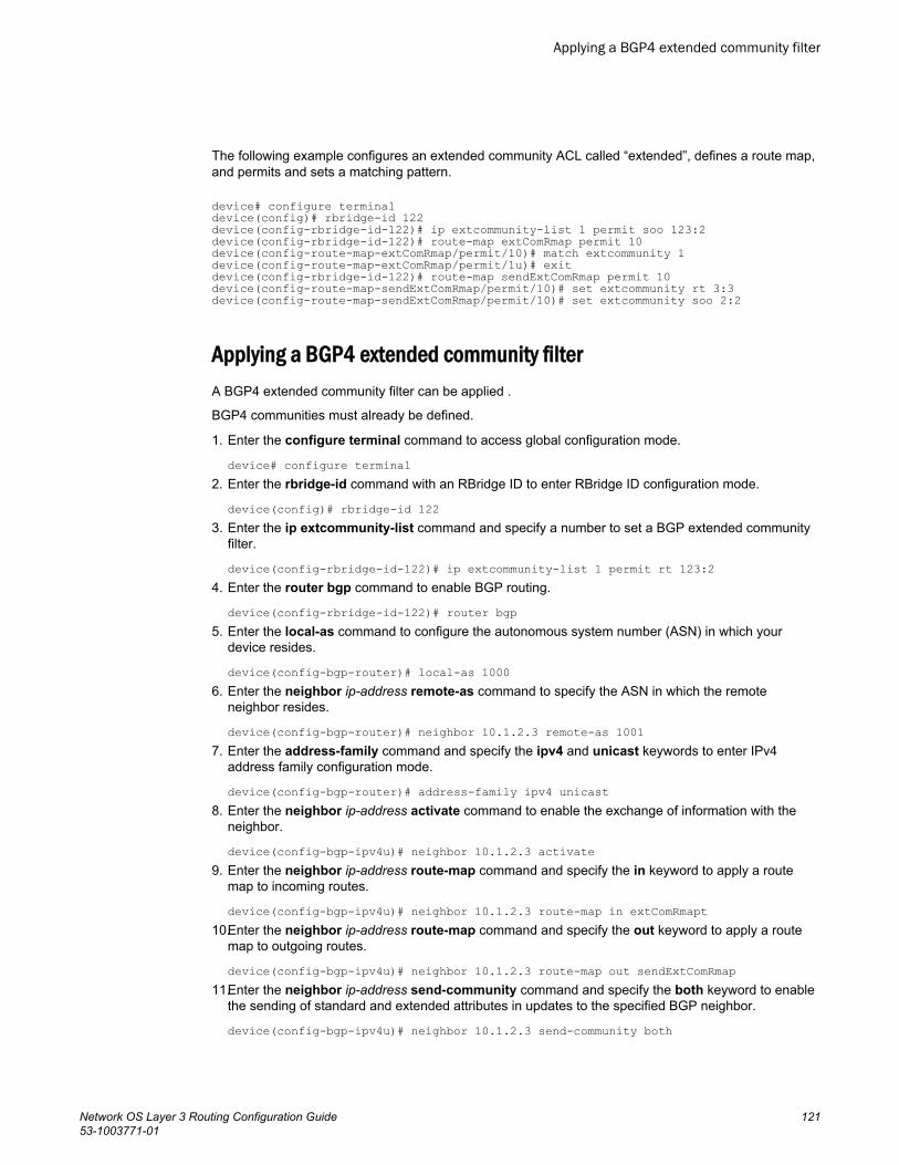
The following example configures an extended community ACL called “extended”, defines a route map,and permits and sets a matching pattern.
device# configure terminaldevice(config)# rbridge-id 122device(config-rbridge-id-122)# ip extcommunity-list 1 permit soo 123:2device(config-rbridge-id-122)# route-map extComRmap permit 10device(config-route-map-extComRmap/permit/10)# match extcommunity 1device(config-route-map-extComRmap/permit/1u)# exitdevice(config-rbridge-id-122)# route-map sendExtComRmap permit 10device(config-route-map-sendExtComRmap/permit/10)# set extcommunity rt 3:3device(config-route-map-sendExtComRmap/permit/10)# set extcommunity soo 2:2
Applying a BGP4 extended community filterA BGP4 extended community filter can be applied .
BGP4 communities must already be defined.
1. Enter the configure terminal command to access global configuration mode.
device# configure terminal2. Enter the rbridge-id command with an RBridge ID to enter RBridge ID configuration mode.
device(config)# rbridge-id 1223. Enter the ip extcommunity-list command and specify a number to set a BGP extended community
filter.
device(config-rbridge-id-122)# ip extcommunity-list 1 permit rt 123:24. Enter the router bgp command to enable BGP routing.
device(config-rbridge-id-122)# router bgp5. Enter the local-as command to configure the autonomous system number (ASN) in which your
device resides.
device(config-bgp-router)# local-as 10006. Enter the neighbor ip-address remote-as command to specify the ASN in which the remote
neighbor resides.
device(config-bgp-router)# neighbor 10.1.2.3 remote-as 10017. Enter the address-family command and specify the ipv4 and unicast keywords to enter IPv4
address family configuration mode.
device(config-bgp-router)# address-family ipv4 unicast8. Enter the neighbor ip-address activate command to enable the exchange of information with the
neighbor.
device(config-bgp-ipv4u)# neighbor 10.1.2.3 activate9. Enter the neighbor ip-address route-map command and specify the in keyword to apply a route
map to incoming routes.
device(config-bgp-ipv4u)# neighbor 10.1.2.3 route-map in extComRmapt 10.Enter the neighbor ip-address route-map command and specify the out keyword to apply a route
map to outgoing routes.
device(config-bgp-ipv4u)# neighbor 10.1.2.3 route-map out sendExtComRmap 11.Enter the neighbor ip-address send-community command and specify the both keyword to enable
the sending of standard and extended attributes in updates to the specified BGP neighbor.
device(config-bgp-ipv4u)# neighbor 10.1.2.3 send-community both
Applying a BGP4 extended community filter
Network OS Layer 3 Routing Configuration Guide 12153-1003771-01
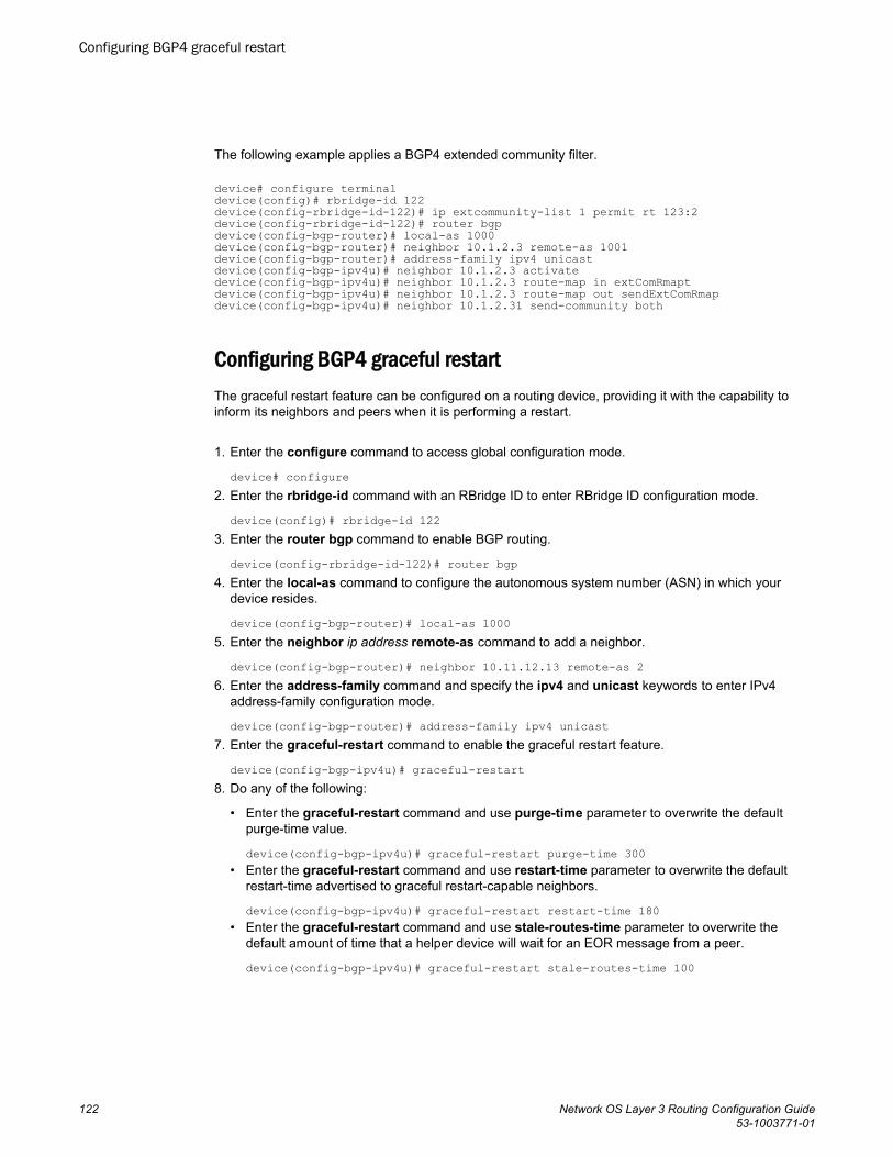
The following example applies a BGP4 extended community filter.
device# configure terminaldevice(config)# rbridge-id 122device(config-rbridge-id-122)# ip extcommunity-list 1 permit rt 123:2device(config-rbridge-id-122)# router bgpdevice(config-bgp-router)# local-as 1000device(config-bgp-router)# neighbor 10.1.2.3 remote-as 1001device(config-bgp-router)# address-family ipv4 unicastdevice(config-bgp-ipv4u)# neighbor 10.1.2.3 activatedevice(config-bgp-ipv4u)# neighbor 10.1.2.3 route-map in extComRmapt device(config-bgp-ipv4u)# neighbor 10.1.2.3 route-map out sendExtComRmap device(config-bgp-ipv4u)# neighbor 10.1.2.31 send-community both
Configuring BGP4 graceful restartThe graceful restart feature can be configured on a routing device, providing it with the capability toinform its neighbors and peers when it is performing a restart.
1. Enter the configure command to access global configuration mode.
device# configure2. Enter the rbridge-id command with an RBridge ID to enter RBridge ID configuration mode.
device(config)# rbridge-id 1223. Enter the router bgp command to enable BGP routing.
device(config-rbridge-id-122)# router bgp4. Enter the local-as command to configure the autonomous system number (ASN) in which your
device resides.
device(config-bgp-router)# local-as 10005. Enter the neighbor ip address remote-as command to add a neighbor.
device(config-bgp-router)# neighbor 10.11.12.13 remote-as 26. Enter the address-family command and specify the ipv4 and unicast keywords to enter IPv4
address-family configuration mode.
device(config-bgp-router)# address-family ipv4 unicast7. Enter the graceful-restart command to enable the graceful restart feature.
device(config-bgp-ipv4u)# graceful-restart8. Do any of the following:
• Enter the graceful-restart command and use purge-time parameter to overwrite the defaultpurge-time value.
device(config-bgp-ipv4u)# graceful-restart purge-time 300• Enter the graceful-restart command and use restart-time parameter to overwrite the default
restart-time advertised to graceful restart-capable neighbors.
device(config-bgp-ipv4u)# graceful-restart restart-time 180• Enter the graceful-restart command and use stale-routes-time parameter to overwrite the
default amount of time that a helper device will wait for an EOR message from a peer.
device(config-bgp-ipv4u)# graceful-restart stale-routes-time 100
Configuring BGP4 graceful restart
122 Network OS Layer 3 Routing Configuration Guide53-1003771-01
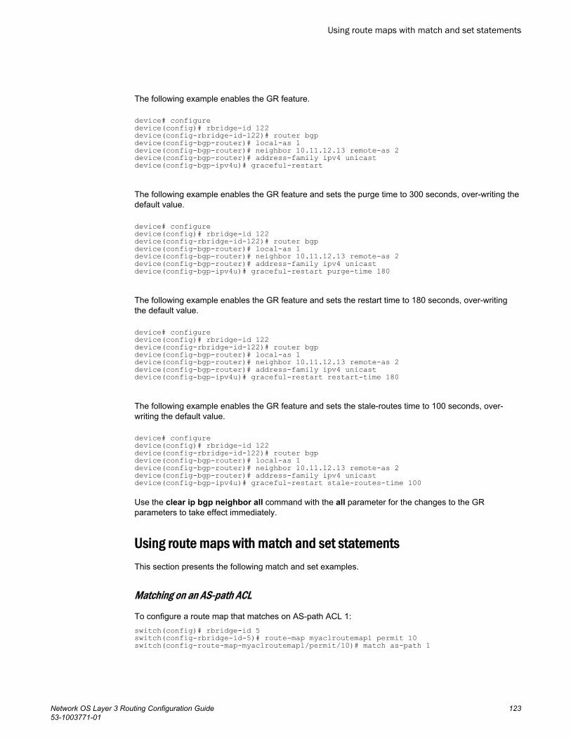
The following example enables the GR feature.
device# configuredevice(config)# rbridge-id 122device(config-rbridge-id-122)# router bgpdevice(config-bgp-router)# local-as 1device(config-bgp-router)# neighbor 10.11.12.13 remote-as 2device(config-bgp-router)# address-family ipv4 unicastdevice(config-bgp-ipv4u)# graceful-restart
The following example enables the GR feature and sets the purge time to 300 seconds, over-writing thedefault value.
device# configuredevice(config)# rbridge-id 122device(config-rbridge-id-122)# router bgpdevice(config-bgp-router)# local-as 1device(config-bgp-router)# neighbor 10.11.12.13 remote-as 2device(config-bgp-router)# address-family ipv4 unicastdevice(config-bgp-ipv4u)# graceful-restart purge-time 180
The following example enables the GR feature and sets the restart time to 180 seconds, over-writingthe default value.
device# configuredevice(config)# rbridge-id 122device(config-rbridge-id-122)# router bgpdevice(config-bgp-router)# local-as 1device(config-bgp-router)# neighbor 10.11.12.13 remote-as 2device(config-bgp-router)# address-family ipv4 unicastdevice(config-bgp-ipv4u)# graceful-restart restart-time 180
The following example enables the GR feature and sets the stale-routes time to 100 seconds, over-writing the default value.
device# configuredevice(config)# rbridge-id 122device(config-rbridge-id-122)# router bgpdevice(config-bgp-router)# local-as 1device(config-bgp-router)# neighbor 10.11.12.13 remote-as 2device(config-bgp-router)# address-family ipv4 unicastdevice(config-bgp-ipv4u)# graceful-restart stale-routes-time 100
Use the clear ip bgp neighbor all command with the all parameter for the changes to the GRparameters to take effect immediately.
Using route maps with match and set statementsThis section presents the following match and set examples.
Matching on an AS-path ACL
To configure a route map that matches on AS-path ACL 1:switch(config)# rbridge-id 5switch(config-rbridge-id-5)# route-map myaclroutemap1 permit 10switch(config-route-map-myaclroutemap1/permit/10)# match as-path 1
Using route maps with match and set statements
Network OS Layer 3 Routing Configuration Guide 12353-1003771-01
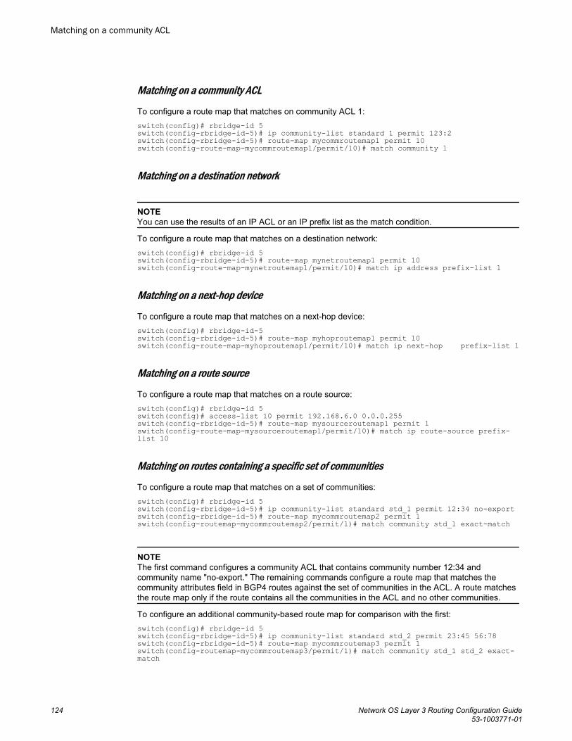
Matching on a community ACL
To configure a route map that matches on community ACL 1:switch(config)# rbridge-id 5switch(config-rbridge-id-5)# ip community-list standard 1 permit 123:2switch(config-rbridge-id-5)# route-map mycommroutemap1 permit 10switch(config-route-map-mycommroutemap1/permit/10)# match community 1
Matching on a destination network
NOTEYou can use the results of an IP ACL or an IP prefix list as the match condition.
To configure a route map that matches on a destination network:switch(config)# rbridge-id 5switch(config-rbridge-id-5)# route-map mynetroutemap1 permit 10switch(config-route-map-mynetroutemap1/permit/10)# match ip address prefix-list 1
Matching on a next-hop device
To configure a route map that matches on a next-hop device:switch(config)# rbridge-id-5 switch(config-rbridge-id-5)# route-map myhoproutemap1 permit 10switch(config-route-map-myhoproutemap1/permit/10)# match ip next-hop prefix-list 1
Matching on a route source
To configure a route map that matches on a route source:switch(config)# rbridge-id 5switch(config)# access-list 10 permit 192.168.6.0 0.0.0.255switch(config-rbridge-id-5)# route-map mysourceroutemap1 permit 1switch(config-route-map-mysourceroutemap1/permit/10)# match ip route-source prefix-list 10
Matching on routes containing a specific set of communities
To configure a route map that matches on a set of communities:switch(config)# rbridge-id 5switch(config-rbridge-id-5)# ip community-list standard std_1 permit 12:34 no-exportswitch(config-rbridge-id-5)# route-map mycommroutemap2 permit 1switch(config-routemap-mycommroutemap2/permit/1)# match community std_1 exact-match
NOTEThe first command configures a community ACL that contains community number 12:34 andcommunity name "no-export." The remaining commands configure a route map that matches thecommunity attributes field in BGP4 routes against the set of communities in the ACL. A route matchesthe route map only if the route contains all the communities in the ACL and no other communities.
To configure an additional community-based route map for comparison with the first:switch(config)# rbridge-id 5switch(config-rbridge-id-5)# ip community-list standard std_2 permit 23:45 56:78switch(config-rbridge-id-5)# route-map mycommroutemap3 permit 1switch(config-routemap-mycommroutemap3/permit/1)# match community std_1 std_2 exact-match
Matching on a community ACL
124 Network OS Layer 3 Routing Configuration Guide53-1003771-01
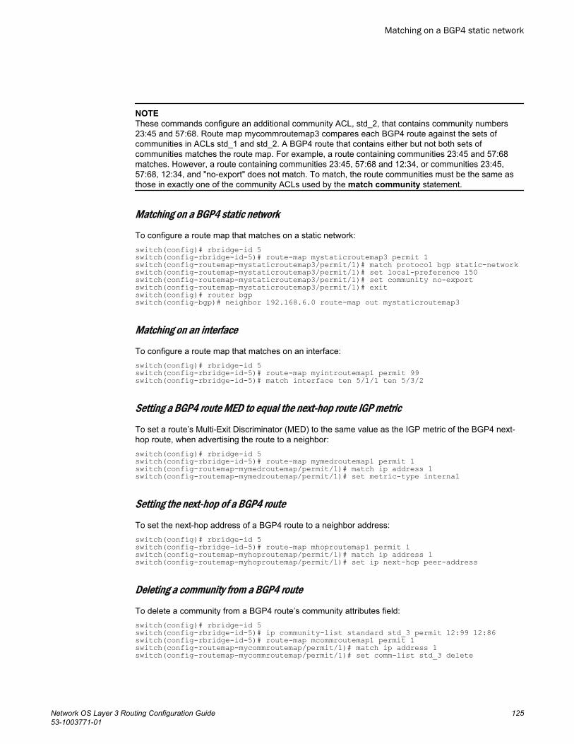
NOTEThese commands configure an additional community ACL, std_2, that contains community numbers23:45 and 57:68. Route map mycommroutemap3 compares each BGP4 route against the sets ofcommunities in ACLs std_1 and std_2. A BGP4 route that contains either but not both sets ofcommunities matches the route map. For example, a route containing communities 23:45 and 57:68matches. However, a route containing communities 23:45, 57:68 and 12:34, or communities 23:45,57:68, 12:34, and "no-export" does not match. To match, the route communities must be the same asthose in exactly one of the community ACLs used by the match community statement.
Matching on a BGP4 static network
To configure a route map that matches on a static network:switch(config)# rbridge-id 5switch(config-rbridge-id-5)# route-map mystaticroutemap3 permit 1switch(config-routemap-mystaticroutemap3/permit/1)# match protocol bgp static-networkswitch(config-routemap-mystaticroutemap3/permit/1)# set local-preference 150switch(config-routemap-mystaticroutemap3/permit/1)# set community no-exportswitch(config-routemap-mystaticroutemap3/permit/1)# exitswitch(config)# router bgpswitch(config-bgp)# neighbor 192.168.6.0 route-map out mystaticroutemap3
Matching on an interface
To configure a route map that matches on an interface:switch(config)# rbridge-id 5 switch(config-rbridge-id-5)# route-map myintroutemap1 permit 99switch(config-rbridge-id-5)# match interface ten 5/1/1 ten 5/3/2
Setting a BGP4 route MED to equal the next-hop route IGP metric
To set a route’s Multi-Exit Discriminator (MED) to the same value as the IGP metric of the BGP4 next-hop route, when advertising the route to a neighbor:switch(config)# rbridge-id 5switch(config-rbridge-id-5)# route-map mymedroutemap1 permit 1switch(config-routemap-mymedroutemap/permit/1)# match ip address 1switch(config-routemap-mymedroutemap/permit/1)# set metric-type internal
Setting the next-hop of a BGP4 route
To set the next-hop address of a BGP4 route to a neighbor address:switch(config)# rbridge-id 5 switch(config-rbridge-id-5)# route-map mhoproutemap1 permit 1switch(config-routemap-myhoproutemap/permit/1)# match ip address 1switch(config-routemap-myhoproutemap/permit/1)# set ip next-hop peer-address
Deleting a community from a BGP4 route
To delete a community from a BGP4 route’s community attributes field:switch(config)# rbridge-id 5switch(config-rbridge-id-5)# ip community-list standard std_3 permit 12:99 12:86switch(config-rbridge-id-5)# route-map mcommroutemap1 permit 1switch(config-routemap-mycommroutemap/permit/1)# match ip address 1switch(config-routemap-mycommroutemap/permit/1)# set comm-list std_3 delete
Matching on a BGP4 static network
Network OS Layer 3 Routing Configuration Guide 12553-1003771-01
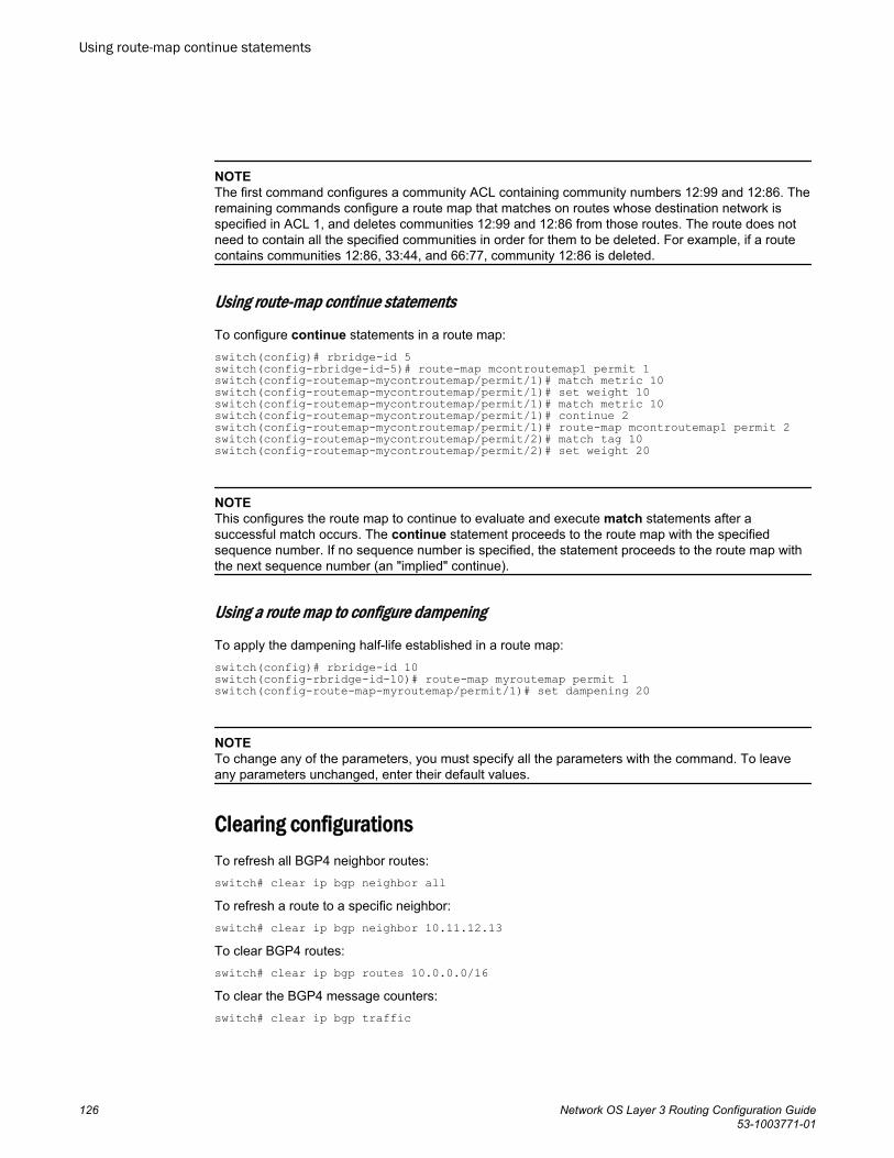
NOTEThe first command configures a community ACL containing community numbers 12:99 and 12:86. Theremaining commands configure a route map that matches on routes whose destination network isspecified in ACL 1, and deletes communities 12:99 and 12:86 from those routes. The route does notneed to contain all the specified communities in order for them to be deleted. For example, if a routecontains communities 12:86, 33:44, and 66:77, community 12:86 is deleted.
Using route-map continue statements
To configure continue statements in a route map:switch(config)# rbridge-id 5switch(config-rbridge-id-5)# route-map mcontroutemap1 permit 1switch(config-routemap-mycontroutemap/permit/1)# match metric 10switch(config-routemap-mycontroutemap/permit/1)# set weight 10switch(config-routemap-mycontroutemap/permit/1)# match metric 10switch(config-routemap-mycontroutemap/permit/1)# continue 2switch(config-routemap-mycontroutemap/permit/1)# route-map mcontroutemap1 permit 2switch(config-routemap-mycontroutemap/permit/2)# match tag 10switch(config-routemap-mycontroutemap/permit/2)# set weight 20
NOTEThis configures the route map to continue to evaluate and execute match statements after asuccessful match occurs. The continue statement proceeds to the route map with the specifiedsequence number. If no sequence number is specified, the statement proceeds to the route map withthe next sequence number (an "implied" continue).
Using a route map to configure dampening
To apply the dampening half-life established in a route map:switch(config)# rbridge-id 10switch(config-rbridge-id-10)# route-map myroutemap permit 1switch(config-route-map-myroutemap/permit/1)# set dampening 20
NOTETo change any of the parameters, you must specify all the parameters with the command. To leaveany parameters unchanged, enter their default values.
Clearing configurationsTo refresh all BGP4 neighbor routes:switch# clear ip bgp neighbor allTo refresh a route to a specific neighbor:switch# clear ip bgp neighbor 10.11.12.13To clear BGP4 routes:switch# clear ip bgp routes 10.0.0.0/16To clear the BGP4 message counters:switch# clear ip bgp traffic
Using route-map continue statements
126 Network OS Layer 3 Routing Configuration Guide53-1003771-01
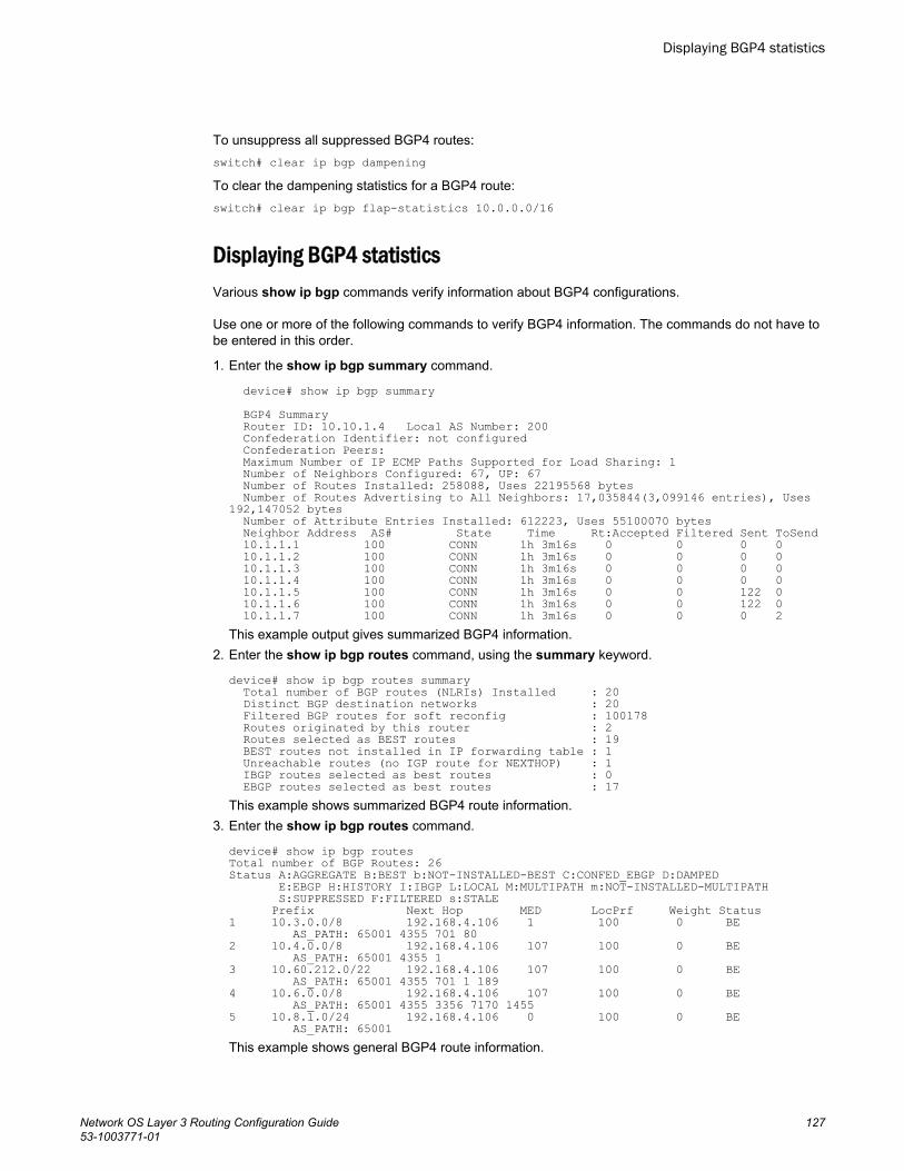
To unsuppress all suppressed BGP4 routes:switch# clear ip bgp dampeningTo clear the dampening statistics for a BGP4 route:switch# clear ip bgp flap-statistics 10.0.0.0/16
Displaying BGP4 statisticsVarious show ip bgp commands verify information about BGP4 configurations.
Use one or more of the following commands to verify BGP4 information. The commands do not have tobe entered in this order.
1. Enter the show ip bgp summary command.
device# show ip bgp summary BGP4 Summary Router ID: 10.10.1.4 Local AS Number: 200 Confederation Identifier: not configured Confederation Peers: Maximum Number of IP ECMP Paths Supported for Load Sharing: 1 Number of Neighbors Configured: 67, UP: 67 Number of Routes Installed: 258088, Uses 22195568 bytes Number of Routes Advertising to All Neighbors: 17,035844(3,099146 entries), Uses 192,147052 bytes Number of Attribute Entries Installed: 612223, Uses 55100070 bytes Neighbor Address AS# State Time Rt:Accepted Filtered Sent ToSend 10.1.1.1 100 CONN 1h 3m16s 0 0 0 0 10.1.1.2 100 CONN 1h 3m16s 0 0 0 0 10.1.1.3 100 CONN 1h 3m16s 0 0 0 0 10.1.1.4 100 CONN 1h 3m16s 0 0 0 0 10.1.1.5 100 CONN 1h 3m16s 0 0 122 0 10.1.1.6 100 CONN 1h 3m16s 0 0 122 0 10.1.1.7 100 CONN 1h 3m16s 0 0 0 2This example output gives summarized BGP4 information.
2. Enter the show ip bgp routes command, using the summary keyword.
device# show ip bgp routes summary Total number of BGP routes (NLRIs) Installed : 20 Distinct BGP destination networks : 20 Filtered BGP routes for soft reconfig : 100178 Routes originated by this router : 2 Routes selected as BEST routes : 19 BEST routes not installed in IP forwarding table : 1 Unreachable routes (no IGP route for NEXTHOP) : 1 IBGP routes selected as best routes : 0 EBGP routes selected as best routes : 17This example shows summarized BGP4 route information.
3. Enter the show ip bgp routes command.
device# show ip bgp routesTotal number of BGP Routes: 26Status A:AGGREGATE B:BEST b:NOT-INSTALLED-BEST C:CONFED_EBGP D:DAMPED E:EBGP H:HISTORY I:IBGP L:LOCAL M:MULTIPATH m:NOT-INSTALLED-MULTIPATH S:SUPPRESSED F:FILTERED s:STALE Prefix Next Hop MED LocPrf Weight Status1 10.3.0.0/8 192.168.4.106 1 100 0 BE AS_PATH: 65001 4355 701 802 10.4.0.0/8 192.168.4.106 107 100 0 BE AS_PATH: 65001 4355 13 10.60.212.0/22 192.168.4.106 107 100 0 BE AS_PATH: 65001 4355 701 1 1894 10.6.0.0/8 192.168.4.106 107 100 0 BE AS_PATH: 65001 4355 3356 7170 14555 10.8.1.0/24 192.168.4.106 0 100 0 BE AS_PATH: 65001 This example shows general BGP4 route information.
Displaying BGP4 statistics
Network OS Layer 3 Routing Configuration Guide 12753-1003771-01
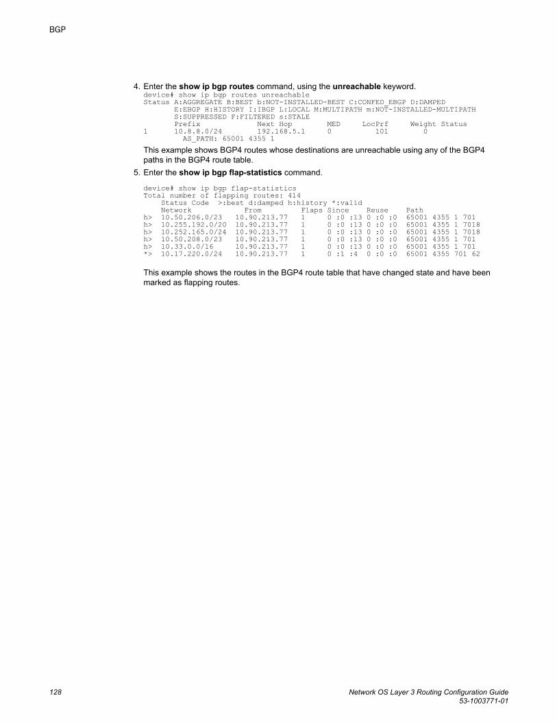
4. Enter the show ip bgp routes command, using the unreachable keyword.device# show ip bgp routes unreachable Status A:AGGREGATE B:BEST b:NOT-INSTALLED-BEST C:CONFED_EBGP D:DAMPED E:EBGP H:HISTORY I:IBGP L:LOCAL M:MULTIPATH m:NOT-INSTALLED-MULTIPATH S:SUPPRESSED F:FILTERED s:STALE Prefix Next Hop MED LocPrf Weight Status1 10.8.8.0/24 192.168.5.1 0 101 0 AS_PATH: 65001 4355 1This example shows BGP4 routes whose destinations are unreachable using any of the BGP4paths in the BGP4 route table.
5. Enter the show ip bgp flap-statistics command.
device# show ip bgp flap-statisticsTotal number of flapping routes: 414 Status Code >:best d:damped h:history *:valid Network From Flaps Since Reuse Pathh> 10.50.206.0/23 10.90.213.77 1 0 :0 :13 0 :0 :0 65001 4355 1 701h> 10.255.192.0/20 10.90.213.77 1 0 :0 :13 0 :0 :0 65001 4355 1 7018h> 10.252.165.0/24 10.90.213.77 1 0 :0 :13 0 :0 :0 65001 4355 1 7018h> 10.50.208.0/23 10.90.213.77 1 0 :0 :13 0 :0 :0 65001 4355 1 701h> 10.33.0.0/16 10.90.213.77 1 0 :0 :13 0 :0 :0 65001 4355 1 701*> 10.17.220.0/24 10.90.213.77 1 0 :1 :4 0 :0 :0 65001 4355 701 62
This example shows the routes in the BGP4 route table that have changed state and have beenmarked as flapping routes.
BGP
128 Network OS Layer 3 Routing Configuration Guide53-1003771-01

BGP4+
● BGP4+ overview........................................................................................................... 129● BGP global mode ......................................................................................................... 129● IPv6 unicast address family.......................................................................................... 130● BGP4+ neighbors..........................................................................................................131● BGP4+ peer groups...................................................................................................... 131● BGP4+ next hop recursion............................................................................................132● BGP4+ NLRIs and next hop attributes..........................................................................132● BGP4+ route reflection..................................................................................................133● BGP4+ route aggregation............................................................................................. 133● BGP4+ multipath...........................................................................................................133● Route maps...................................................................................................................134● BGP4+ outbound route filtering.....................................................................................134● BGP4+ confederations..................................................................................................134● BGP4+ extended community........................................................................................ 135● BGP4+ graceful restart..................................................................................................135● Configuring BGP4+....................................................................................................... 135
BGP4+ overviewThe implementation of IPv6 supports multiprotocol BGP (MBGP) extensions that allow Border GatewayProtocol version 4 plus (BGP4+) to distribute routing information. BGP4+ supports all of the samefeatures and functionality as IPv4 BGP (BGP4).
IPv6 MBGP enhancements include:
• An IPv6 unicast address family and network layer reachability information (NLRI)• Next hop attributes that use IPv6 addresses
NOTEThe implementation of BGP4+ supports the advertising of routes among different address families.However, it supports BGP4+ unicast routes only; it does not currently support BGP4+ multicast routes.
BGP global modeConfigurations that are not specific to address family configuration are available in the BGP globalconfiguration mode.
device(config-bgp-router)# ?Possible completions: address-family Enter Address Family command mode always-compare-med Allow comparing MED from different neighbors
Network OS Layer 3 Routing Configuration Guide 12953-1003771-01
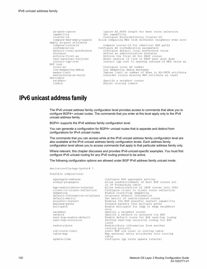
as-path-ignore Ignore AS_PATH length for best route selection capability Set capability cluster-id Configure Route-Reflector Cluster-ID compare-med-empty-aspath Allow comparing MED from different neighbors even with empty as-path attribute compare-routerid Compare router-id for identical BGP paths confederation Configure AS confederation parameters default-local-preference Configure default local preference value distance Define an administrative distance enforce-first-as Enforce the first AS for EBGP routes fast-external-fallover Reset session if link to EBGP peer goes down install-igp-cost Install igp cost to nexthop instead of MED value as BGP cost local-as Configure local AS number log-dampening-debug Log dampening debug messages maxas-limit Impose limit on number of ASes in AS-PATH attribute med-missing-as-worst Consider routes missing MED attribute as least desirable neighbor Specify a neighbor router timers Adjust routing timers
IPv6 unicast address familyThe IPv6 unicast address family configuration level provides access to commands that allow you toconfigure BGP4+ unicast routes. The commands that you enter at this level apply only to the IPv6unicast address family.
BGP4+ supports the IPv6 address family configuration level.
You can generate a configuration for BGP4+ unicast routes that is separate and distinct fromconfigurations for IPv4 unicast routes.
The commands that you can access while at the IPv6 unicast address family configuration level arealso available at the IPv4 unicast address family configuration levels. Each address familyconfiguration level allows you to access commands that apply to that particular address family only.
Where relevant, this chapter discusses and provides IPv6-unicast-specific examples. You must firstconfigure IPv6 unicast routing for any IPv6 routing protocol to be active.
The following configuration options are allowed under BGP IPv6 address family unicast mode:
device(config-bgp-ipv6u)# ?Possible completions: aggregate-address Configure BGP aggregate entries always-propagate Allow readvertisement of best BGP routes not in IP Forwarding table bgp-redistribute-internal Allow redistribution of iBGP routes into IGPs client-to-client-reflection Configure client to client route reflection dampening Enable route-flap dampening default-information-originate Originate Default Information default-metric Set metric of redistributed routes graceful-restart Enables the BGP graceful restart capability maximum-paths Forward packets over multiple paths multipath Enable multipath for ibgp or ebgp neighbors only neighbor Specify a neighbor router network Specify a network to announce via BGP next-hop-enable-default Enable default route for BGP next-hop lookup next-hop-recursion Perform next-hop recursive lookup for BGP route redistribute Redistribute information from another routing protocol rib-route-limit Limit BGP rib count in routing table table-map Map external entry attributes into routing table update-time Configure igp route update interval
IPv6 unicast address family
130 Network OS Layer 3 Routing Configuration Guide53-1003771-01
BGP4+ neighborsBGP4+ neighbors can be configured using link-local addresses or global addresses.
BGP4+ neighbors can be created using link-local addresses for peers in the same link. For link-localpeers, the neighbor interface over which the neighbor and local device exchange prefixes is specifiedthrough the neighbor update-source command, and a route map is configured to set up a global nexthop for packets destined for the neighbor.
To configure BGP4+ neighbors that use link-local addresses, you must do the following:
• Add the IPv6 address of a neighbor in a remote autonomous system (AS) to the BGP4+ neighbortable of the local device.
• Identify the neighbor interface over which the neighbor and local device will exchange prefixes usingthe neighbor update-source command.
• Configure a route map to set up a global next hop for packets destined for the neighbor.
The neighbor should be activated in the IPv6 address family configuration mode using the neighboractivate command.
BGP4+ neighbors can also be configured using a global address. The global IPv6 address of aneighbor in a remote AS must be added, and the neighbor should be activated in the IPv6 addressfamily configuration mode using the neighbor activate command.
BGP4+ peer groupsNeighbors having the same attributes and parameters can be grouped together by means of the peer-group command.
You must first create a peer group, after which you can associate neighbor IPv6 addresses with thepeer group. All of the attributes that are allowed on a neighbor are allowed on a peer group as well.
BGP4+ peers and peer groups are activated in the IPv6 address family configuration mode to establishthe BGP4+ peering sessions.
An attribute value configured explicitly for a neighbor takes precedence over the attribute valueconfigured on the peer group. In the case where neither the peer group nor the individual neighbor hasthe attribute configured, the default value for the attribute is used.
NOTEBGP4 neighbors are established and the prefixes are advertised using the neighbor IP addressremote-as command in router BGP mode. However, when establishing BGP4+ peer sessions andexchanging IPv6 prefixes, neighbors must also be activated using the neighbor IPv6 address activatecommand in IPv6 address family configuration mode.
NOTEYou can add IPv6 neighbors only to an IPv6 peer group. You cannot add an IPv4 neighbor to an IPv6peer group and vice versa. IPv4 and IPv6 peer groups must remain separate.
BGP4+ neighbors
Network OS Layer 3 Routing Configuration Guide 13153-1003771-01
BGP4+ next hop recursionA device can find the IGP route to the next-hop gateway for a BGP4+ route.
For each BGP4+ route learned, the device performs a route lookup to obtain the IPv6 address of thenext hop for the route. A BGP4+ route is eligible for addition in the IPv6 route table only if the followingconditions are true:
• The lookup succeeds in obtaining a valid next-hop IPv6 address for the route.• The path to the next-hop IPv6 address is an IGP path or a static route path.
By default, the software performs only one lookup for the next-hop IPv6 address for the BGP4+ route.If the next hop lookup does not result in a valid next hop IPv6 address, or the path to the next hop IPv6address is a BGP4+ path, the BGP4+ route destination is considered unreachable. The route is noteligible to be added to the IPv6 route table.
The BGP4+ route table can contain a route with a next hop IPv6 address that is not reachable throughan IGP route, even though the device can reach a hop farther away through an IGP route. This canoccur when the IGPs do not learn a complete set of IGP routes, so the device learns about an internalroute through IBGP instead of through an IGP. In this case, the IPv6 route table will not contain a routethat can be used to reach the BGP4+ route destination.
To enable the device to find the IGP route to the next-hop gateway for a BGP4+ route, enablerecursive next-hop lookups. With this feature enabled, if the first lookup for a BGP4+ route results inan IBGP path that originated within the same AS, rather than an IGP path or static route path, thedevice performs a lookup on the next hop IPv6 address for the next hop gateway. If this second lookupresults in an IGP path, the software considers the BGP4+ route to be valid and adds it to the IPv6route table. Otherwise, the device performs another lookup on the next hop IPv6 address of the nexthop for the next hop gateway, and so on, until one of the lookups results in an IGP route.
You must configure a static route or use an IGP to learn the route to the EBGP multihop peer.
BGP4+ NLRIs and next hop attributesBGP4+ introduces new attributes to handle multiprotocol extensions for BGP.
Multiprotocol BGP (MBGP) is an extension to BGP that enables BGP to carry routing information formultiple address families.
BGP4+ introduces new attributes to handle multiprotocol extensions for BGP:
• Multiprotocol reachable Network Layer Reachability Information (MP_REACH_NLRI): Used to carrythe set of reachable destinations, together with the next hop information, to be used for forwardingto these destinations.
• Multiprotocol unreachable NLRI (MP_UNREACH_NLRI): Used to carry the set of unreachabledestinations.
MP_REACH_NLRI and MP_UNREACH_NLRI are optional and non-transitive, so that a BGP4+speaker that does not support the multiprotocol capabilities ignores the information carried in theseattributes, and does not pass it to other BGP4+ speakers. A BGP speaker that uses multiprotocolextensions for IPv6 uses the capability advertisement procedures to determine whether the speakercan use multiprotocol extensions with a particular peer.
The next hop information carried in the MP_REACH_NLRI path attribute defines the network layeraddress of the border router that will be used as the next hop to the destinations listed in the MP_NLRIattribute in the UPDATE message.
MP_REACH_NLRI and MP_UNREACH_NLRI carry IPv6 prefixes.
BGP4+ next hop recursion
132 Network OS Layer 3 Routing Configuration Guide53-1003771-01
BGP4+ route reflectionA BGP device can act as a route-reflector client or as a route reflector. You can configure a BGP peeras a route-reflector client from the device that is going to reflect the routes and act as the route reflectorusing the neighbor route-reflector-client command.
When there is more than one route reflector, they should all belong to the same cluster. By default, thevalue for cluster-id is used as the device ID. The device ID can be changed using the cluster-idcommand.
The route-reflector server reflects the routes as follows:
• Routes from the client are reflected to the client as well as to nonclient peers.• Routes from nonclient peers are reflected only to client peers.
If route-reflector clients are connected in a full IBGP mesh, you can disable client-to-client reflection onthe route reflector using the no client-to-client-reflection command.
A BGP device advertises only those routes that are preferred ones and are installed into the RoutingTable Manager (RTM). When a route cannot be installed into the RTM because the routing table is full,the route reflector may not reflect that route. In cases where the route reflector is not placed directly inthe forwarding path, you can configure the route reflector to reflect routes even though those routes arenot in the RTM using the always-propagate command.
BGP4+ route aggregationA device can be configured to aggregate routes in a range of networks into a single IPv6 prefix.
By default, a device advertises individual BGP4+ routes for all the networks. The aggregation featureallows you to configure a device to aggregate routes in a range of networks into a single IPv6 prefix. Forexample, without aggregation, a device will individually advertise routes for networks2001:db8:0001:0000::/64, 2001:db8:0002:0000::/64, 2001:db8:0003:0000::/64, and so on. You canconfigure the device to send a single, aggregate route for the networks instead so that the aggregateroute would be advertised as 2001:db8::/32 to BGP4 neighbors.
BGP4+ multipathThe BGP4+ multipath feature can be used to enable load-balancing across different paths.
BGP4+ selects only one best path for each IPv6 prefix it receives before installing it in the IP routingtable. If you need load-balancing across different paths, you must enable BGP4+ multipath using themaximum-paths command under IPv6 address family configuration mode.
IBGP paths and EBGP paths can be exclusively selected, or a combination of IBGP and EBGP pathscan be selected.
The following attributes of parallel paths must match for them to be considered for multipathing:
• Weight• Local Preference• Origin• AS-Path Length• MED
BGP4+ route reflection
Network OS Layer 3 Routing Configuration Guide 13353-1003771-01
• Neighbor AS (EBGP multipath)• AS-PATH match (for IBGP multipath)• IGP metric to BGP next hop
Route mapsRoute maps must be applied to IPv6 unicast address prefixes in IPv6 address family configurationmode.
By default, route maps that are applied under IPv4 address family configuration mode using theneighbor route-map command are applied to only IPv4 unicast address prefixes. To apply routemaps to IPv6 unicast address prefixes, the neighbor route-map command must be used in IPv6address family configuration mode. The route maps are applied as the inbound or outbound routingpolicy for neighbors under the specified address family. Configuring separate route maps under eachaddress family type simplifies managing complicated or different policies for each address family.
BGP4+ outbound route filteringThe BGP4+ Outbound Route Filtering Capability (ORF) feature is used to minimize the number ofBGP updates sent between BGP peers.
When the ORF feature is enabled, unwanted routing updates are filtered out, reducing the amount ofsystem resources required for generating and processing routing updates. The ORF feature is enabledthrough the advertisement of ORF capabilities to peer routers. The locally configured BGP4+ inboundprefix filters are sent to the remote peer so that the remote peer applies the filter as an outbound filterfor the neighbor.
The ORF feature can be configured with send and receive ORF capabilities. The local peer advertisesthe ORF capability in send mode, indicating that it will accept a prefix list from a neighbor and applythe prefix list to locally configured ORFs. The local peer exchanges the ORF capability in send modewith a remote peer for a prefix list that is configured as an inbound filter for that peer locally. Theremote peer only sends the first update once it receives a ROUTEREFRESH request or BGP ORFwith IMMEDIATE from the peer. The local and remote peers exchange updates to maintain the ORFon each router.
BGP4+ confederationsA large autonomous system (AS) can be divided into multiple subautonomous systems and groupedinto a single BGP4+ confederation.
Each subautonomous system must be uniquely identified within the confederation AS by asubautonomous system number. Within each subautonomous system, all the rules of internal BGP(IBGP) apply. For example, all BGP routers inside the subautonomous system must be fully meshed.Although EBGP is used between subautonomous systems, the subautonomous systems within theconfederation exchange routing information like IBGP peers. Next hop, Multi Exit Discriminator (MED),and local preference information is preserved when crossing subautonomous system boundaries. Tothe outside world, a confederation looks like a single AS.
The AS path list is a loop-avoidance mechanism used to detect routing updates leaving onesubautonomous system and attempting to re-enter the same subautonomous system. A routing
Route maps
134 Network OS Layer 3 Routing Configuration Guide53-1003771-01
update attempting to re-enter a subautonomous system it originated from is detected because thesubautonomous system sees its own subautonomous system number listed in the update's AS path.
BGP4+ extended communityThe BGP4+ extended community feature filters routes based on a regular expression specified when aroute has multiple community values in it.
A BGP community is a group of destinations that share a common property. Community informationidentifying community members is included as a path attribute in BGP UPDATE messages. You canperform actions on a group using community and extended community attributes to trigger routingdecisions. All communities of a particular type can be filtered out, or certain values can be specified fora particular type of community. You can also specify whether a particular community is transitive or non-transitive across an autonomous system (AS) boundary.
An extended community is an 8-octet value and provides a larger range for grouping or categorizingcommunities. BGP extended community attributes are specified in RFC 4360.
You define the extended community list using the ip extcommunity-list command. The extendedcommunity can then be matched or applied to the neighbor through the route map. The route map mustbe applied on the neighbor to which routes need to carry the extended community attributes. The "send-community" should be enabled for the neighbor configuration to start including the attributes whilesending updates to the neighbor.
BGP4+ graceful restartBGP4+ graceful restart (GR) allows for restarts where neighboring devices participate in the restart,helping to ensure that no route and topology changes occur in the network for the duration of therestart.
The GR feature provides a routing device with the capability to inform its neighbors and peers when it isperforming a restart.
When a BGP session is established, GR capability for BGP is negotiated by neighbors and peersthrough the BGP OPEN message. If the neighbor also advertises support for GR, GR is activated forthat neighbor session. If both peers do not exchange the GR capability, the session is not GR-capable.If the BGP session is lost, the BGP peer router, known as a GR helper, marks all routes associated withthe device as “stale” but continues to forward packets to these routes for a set period of time. Therestarting device also continues to forward packets for the duration of the graceful restart. When thegraceful restart is complete, routes are obtained from the helper so that the device is able to quicklyresume full operation.
When the GR feature is configured on a device, both helper router and restarting router functionalitiesare supported. It is not possible to disable helper functionality explicitly.
GR is disabled by default and can be enabled in both IPv4 and IPv6 address families. When the GRtimer expires, the BGP RASlog message is triggered.
Configuring BGP4+
BGP4+ extended community
Network OS Layer 3 Routing Configuration Guide 13553-1003771-01
Configuring BGP4+ neighbors using global IPv6 addressesBGP4+ neighbors can be configured using global IPv6 addresses.
1. Enter the configure terminal command to access global configuration mode.
device# configure terminal2. Enter the rbridge-id command with an RBridge ID to enter RBridge ID configuration mode.
device(config)# rbridge-id 1223. Enter the router bgp command to enable BGP routing.
device(config-rbridge-id-122)# router bgp4. Enter the local-as command to configure the autonomous system number (ASN) in which your
device resides.
device(config-bgp-router)# local-as 10005. Enter the neighbor ipv6-address remote-as command to specify the ASN in which the remote
neighbor resides.
device(config-bgp-router)# neighbor 2001:db8:93e8:cc00::1 remote-as 10016. Enter the address family command and specify the ipv6 and unicast keywords to enter IPv6
address family configuration mode.
device(config-bgp-router)# address-family ipv6 unicast7. Enter the neighbor ipv6-address activate command to enable the exchange of information with the
neighbor.
device(config-bgp-ipv6u)# neighbor 2001:db8:93e8:cc00::1 activate
The following example configures a neighbor using a global IPv6 address.
device# configure terminaldevice(config)# rbridge-id 122device(config-rbridge-id-122)# router bgpdevice(config-bgp-router)# local-as 1000device(config-bgp-router)# neighbor 2001:db8:93e8:cc00::1 remote-as 1001device(config-bgp-router)# address-family ipv6 unicastdevice(config-bgp-ipv6u)# neighbor 2001:db8:93e8:cc00::1 activate
Configuring BGP4+ neighbors using link-local addressesBGP4+ neighbors can be configured using link-local addresses.
1. Enter the configure terminal command to access global configuration mode.
device# configure terminal2. Enter the rbridge-id command with an RBridge ID to enter RBridge ID configuration mode.
device(config)# rbridge-id 1223. Enter the router bgp command to enable BGP routing.
device(config-rbridge-id-122)# router bgp4. Enter the local-as command to configure the autonomous system number (ASN) in which your
device resides.
device(config-bgp-router)# local-as 1000
Configuring BGP4+ neighbors using global IPv6 addresses
136 Network OS Layer 3 Routing Configuration Guide53-1003771-01
5. Enter the neighbor ipv6-address remote-as command to specify the ASN in which the remoteneighbor resides.
device(config-bgp-router)# neighbor fe80:4398:ab30:45de::1 remote-as 10016. Enter the neighbor ipv6-address update-source command to specify an interface.
device(config-bgp-router)# neighbor fe80:4398:ab30:45de::1 update-source tengigabitethernet 122/3/1
7. Enter the address-family command and specify the ipv6 and unicast keywords to enter IPv6address family configuration mode.
device(config-bgp-router)# address-family ipv6 unicast8. Enter the neighbor ipv6-address activate command to enable the exchange of information with the
neighbor.
device(config-bgp-ipv6u)# neighbor fe80:4398:ab30:45de::1 activate9. Enter the neighbor ipv6-address route-map command and specify the out to apply a route map to
outgoing routes.
device(config-bgp-ipv6u)# neighbor fe80:4398:ab30:45de::1 route-map out myroutemap10.Enter the exit command until you return to Rbridge-ID configuration mode.
device(config-bgp-ipv6u)# exit11.Enter the route-map name permit command to define the route map and enter route-map
configuration mode.
device(config-rbridge-id-122)# route-map myroutemap permit 1012.Enter the set ipv6 next-hop command and specify and IPv6 address to set the IPv6 address of the
next hop.
device(config-route-map-myroutemap/permit/10)# set ipv6 next-hop 2001::10
The following example configures a neighbor using a link-local address and configures a route map toset up a global next hop for packets destined for the neighbor.
device# configure terminaldevice(config)# rbridge-id 122device(config-rbridge-id-122)# router bgpdevice(config-bgp-router)# local-as 1000device(config-bgp-router)# neighbor fe80:4398:ab30:45de::1 remote-as 1001device(config-bgp-router)# neighbor fe80:4398:ab30:45de::1 update-source tengigabitethernet 122/3/1device(config-bgp-router)# address-family ipv6 unicastdevice(config-bgp-ipv6u)# neighbor fe80:4398:ab30:45de::1 activatedevice(config-bgp-ipv6u)# neighbor fe80:4398:ab30:45de::1 route-map out myroutemapdevice(config-bgp-ipv6u)# exitdevice(config-bgp-router)# exitdevice(config-rbridge-id-122)# route-map myroutemap permit 10device(config-route-mapmyroutemap/permit/10)#set ipv6 next-hop 2001::10
Configuring BGP4+ peer groupsA peer group can be created and neighbor IPv6 addresses can be associated with the peer group. Thepeer group is then activated in the IPv6 address family configuration mode.
1. Enter the configure terminal command to access global configuration mode.
device# configure terminal2. Enter the rbridge-id command with an RBridge ID to enter RBridge ID configuration mode.
device(config)# rbridge-id 122
Configuring BGP4+ peer groups
Network OS Layer 3 Routing Configuration Guide 13753-1003771-01
3. Enter the router bgp command to enable BGP routing.
device(config-rbridge-id-122)# router bgp4. Enter the local-as command to configure the autonomous system number (ASN) in which your
device resides.
device(config-bgp-router)# local-as 10005. Enter the neighbor peer-group-name peer-group command to create a peer group.
device(config-bgp-router)# neighbor mypeergroup1 peer-group 6. Enter the neighbor peer-group-name remote-as command to specify the ASN of the peer group.
device(config-bgp-router)# neighbor mypeergroup1 remote-as 117. Enter the neighbor ipv6-address peer-group command to associate a neighbor with the peer
group.
device(config-bgp-router)# neighbor 2001:2018:8192::125 peer-group mypeergroup18. Enter the neighbor ipv6-address peer-group command to associate a neighbor with the peer
group.
device(config-bgp-router)# neighbor 2001:2018:8192::124 peer-group mypeergroup19. Enter the address-family command and specify the ipv6 and unicast keywords to enter IPv6
address family configuration mode.
device(config-bgp-router)# address-family ipv6 unicast10.Enter the neighbor peer-group-name activate command to establish an IPv6 BGP session with the
peer group.
device(config-bgp-ipv6u)# neighbor mypeergroup1 activate
The following example creates a peer group, specifying two neighbors to belong to the peer group,and activates the peer group.
device# configure terminaldevice(config)# rbridge-id 122device(config-rbridge-id-122)# router bgpdevice(config-bgp-router)# local-as 1000device(config-bgp-router)# neighbor mypeergroup1 peer-groupdevice(config-bgp-router)# neighbor mypeergroup1 remote-as 11device(config-bgp-router)# neighbor 2001:2018:8192::125 peer-group mypeergroup1device(config-bgp-router)# neighbor 2001:2018:8192::124 peer-group mypeergroup1device(config-bgp-router)# address-family ipv6 unicastdevice(config-bgp-ipv6u)# neighbor mypeergroup1 activate
Configuring a peer group with IPv4 and IPv6 peersA peer group that contains both IPv4 and IPv6 peers can be configured.
1. Enter the configure terminal command to access global configuration mode.
device# configure terminal2. Enter the rbridge-id command with an RBridge ID to enter RBridge ID configuration mode.
device(config)# rbridge-id 1223. Enter the router bgp command to enable BGP routing.
device(config-rbridge-id-122)# router bgp4. Enter the local-as command to configure the autonomous system number (ASN) in which your
device resides.
device(config-bgp-router)# local-as 1000
Configuring a peer group with IPv4 and IPv6 peers
138 Network OS Layer 3 Routing Configuration Guide53-1003771-01
5. Enter the neighbor peer-group-name peer-group command to create a peer group.
device(config-bgp-router)# neighbor p1 peer-group 6. Enter the neighbor peer-group-name remote-as command to specify the ASN of the peer group.
device(config-bgp-router)# neighbor p1 remote-as 117. Enter the neighbor ipv6-address peer-group command to associate a neighbor with the peer group.
device(config-bgp-router)# neighbor 2001:2018:8192::124 peer-group p18. Enter the neighbor ip address peer-group command to associate a neighbor with the peer group.
device(config-bgp-router)# neighbor 10.0.0.1 peer-group p19. Enter the address-family command and specify the ipv6 and unicast keywords to enter IPv6
address family configuration mode.
device(config-bgp-router)# address-family ipv6 unicast10.Enter the neighbor peer-group-name activate command to establish an IPv6 BGP session with the
peer group.
device(config-bgp-ipv6u)# neighbor p1 activate
The following example creates a peer group with both IPv6 and IPv4 peers and activates the peer groupin the IPv6 address family.
device# configure terminaldevice(config)# rbridge-id 122device(config-rbridge-id-122)# router bgpdevice(config-bgp-router)# local-as 1000device(config-bgp-router)# neighbor p1 peer-groupdevice(config-bgp-router)# neighbor p1 remote-as 11device(config-bgp-router)# neighbor 2001:2018:8192::124 peer-group p1device(config-bgp-router)# neighbor 10.0.0.1 peer-group p1device(config-bgp-router)# address-family ipv6 unicastdevice(config-bgp-ipv6u)# neighbor p1 activate
Importing routes into BGP4+Routes can be explicitly specified for advertisement by BGP.
The routes imported into BGP4+ must first exist in the IPv6 unicast route table.
1. Enter the configure terminal command to access global configuration mode.
device# configure terminal2. Enter the rbridge-id command with an RBridge ID to enter RBridge ID configuration mode.
device(config)# rbridge-id 1223. Enter the router bgp command to enable BGP routing.
device(config-rbridge-id-122)# router bgp4. Enter the address-family command and specify the ipv6 and unicast keywords to enter IPv6
address family configuration mode.
device(config-bgp-router)# address-family ipv6 unicast5. Enter the network command and specify a network/mask to import the specified prefix into the
BGP4+ database.
device(config-bgp-ipv6u)# network 2001:db8::/32
Importing routes into BGP4+
Network OS Layer 3 Routing Configuration Guide 13953-1003771-01
The following example imports the 2001:db8::/32 prefix in to the BGP4+ database for advertising.
device# configure terminaldevice(config)# rbridge-id 122device(config-rbridge-id-122)# router bgpdevice(config-bgp-router)# neighbor fe80:4398:ab30:45de::1 remote-as 1001device(config-bgp-router)# address-family ipv6 unicastdevice(config-bgp-ipv6u)# network 2001:db8::/32
Advertising the default BGP4+ routeA BGP device can be configured to advertise the default IPv6 route to all BGP4+ neighbors and toinstall that route in the local BGP4+ route table.
The default route must be present in the local IPv6 route table.
1. Enter the configure terminal command to access global configuration mode.
device# configure terminal2. Enter the rbridge-id command with an RBridge ID to enter RBridge ID configuration mode.
device(config)# rbridge-id 1223. Enter the router bgp command to enable BGP routing.
device(config-rbridge-id-122)# router bgp4. Enter the address-family command and specify the ipv6 and unicast keywords to enter IPv6
address family configuration mode.
device(config-bgp-router)# address-family ipv6 unicast5. Enter the default-information-originate command to advertise the default IPv6 route to all BGP4+
neighbors and to install that route in the local BGP4+ route table.
device(config-bgp-ipv6u)# default-information-originate
The following example enables a BGP4+ device to advertise the default IPv6 route to all BGP4+neighbors and to install that route in the local BGP4+ route table.
device# configure terminaldevice(config)# rbridge-id 122device(config-rbridge-id-122)# router bgpdevice(config-bgp-router)# address-family ipv6 unicastdevice(config-bgp-ipv6u)# default-information-originate
Advertising the default BGP4+ route to a specific neighborA BGP device can be configured to advertise the default IPv6 route to a specific neighbor.
1. Enter the configure terminal command to access global configuration mode.
device# configure terminal2. Enter the rbridge-id command with an RBridge ID to enter RBridge ID configuration mode.
device(config)# rbridge-id 1223. Enter the router bgp command to enable BGP routing.
device(config-rbridge-id-122)# router bgp
Advertising the default BGP4+ route
140 Network OS Layer 3 Routing Configuration Guide53-1003771-01
4. Enter the local-as command to configure the autonomous system number (ASN) in which yourdevice resides.
device(config-bgp-router)# local-as 10005. Enter the address-family command and specify the ipv6 and unicast keywords to enter IPv6
address family configuration mode.
device(config-bgp-router)# address-family ipv6 unicast6. Enter the neighbor default-originate command and specify an IPv6 address to enable the BGP4+
device to advertise the default IPv6 route to a specific neighbor.
device(config-bgp-ipv6u)# neighbor 2001:db8:93e8:cc00::1 default-originate
The following example enables a BGP4+ device to advertise the default IPv6 route to a specificneighbor.
device# configure terminaldevice(config)# rbridge-id 122device(config-rbridge-id-122)# router bgpdevice(config-bgp-router)# local-as 1000device(config-bgp-router)# address-family ipv6 unicastdevice(config-bgp-ipv6u)# neighbor 2001:db8:93e8:cc00::1 default-originate
Using the IPv6 default route as a valid next hop for a BGP4+ routeIn certain cases, such as when a device is acting as an edge device, it can be configured to use thedefault route as a valid next hop.
By default, a device does not use a default route to resolve a BGP4+ next-hop route. If the IPv6 routelookup for the BGP4+ next-hop does not result in a valid IGP route (including static or direct routes), theBGP4+ next-hop is considered to be unreachable and the BGP4+ route is not used. You can configurethe device to use the default route as a valid next hop.
1. Enter the configure terminal command to access global configuration mode.
device# configure terminal2. Enter the rbridge-id command with an RBridge ID to enter RBridge ID configuration mode.
device(config)# rbridge-id 1223. Enter the router bgp command to enable BGP routing.
device(config-rbridge-id-122)# router bgp4. Enter the address-family command and specify the ipv6 and unicast keywords to enter IPv6
address family configuration mode.
device(config-bgp-router)# address-family ipv6 unicast5. Enter the next-hop-enable-default command to configure the device to use the default route as a
valid next hop.
device(config-bgp-ipv6u)# next-hop-enable-default
The following example configures a BGP4+ device to use the default route as a valid next hop.
device# configure terminaldevice(config)# rbridge-id 122device(config-rbridge-id-122)# router bgpdevice(config-bgp-router)# address-family ipv6 unicastdevice(config-bgp-ipv6u)# next-hop-enable-default
Using the IPv6 default route as a valid next hop for a BGP4+ route
Network OS Layer 3 Routing Configuration Guide 14153-1003771-01
Enabling next-hop recursionNext hop recursion can be enabled so that a device can find the IGP route to the next hop gateway fora BGP4+ route.
1. Enter the configure terminal command to access global configuration mode.
device# configure terminal2. Enter the rbridge-id command with an RBridge ID to enter RBridge ID configuration mode.
device(config)# rbridge-id 1223. Enter the router bgp command to enable BGP routing.
device(config-rbridge-id-122)# router bgp4. Enter the address-family command and specify the ipv6 and unicast keywords to enter IPv6
address family configuration mode.
device(config-bgp-router)# address-family ipv6 unicast5. Enter the next-hop-recursion command to enable recursive next hop lookups.
device(config-bgp-ipv6u)# next-hop-recursion
The following example enables recursive next hop lookups.
device# configure terminaldevice(config)# rbridge-id 122device(config-rbridge-id-122)# router bgpdevice(config-bgp-router)# address-family ipv6 unicastdevice(config-bgp-ipv6u)# next-hop-recursion
Configuring a cluster ID for a route reflectorThe cluster ID can be changed if there is more than one route reflector, so that all route reflectorsbelong to the same cluster.
1. Enter the configure terminal command to access global configuration mode.
device# configure terminal2. Enter the rbridge-id command with an RBridge ID to enter RBridge ID configuration mode.
device(config)# rbridge-id 1223. Enter the router bgp command to enable BGP routing.
device(config-rbridge-id-122)# router bgp4. Enter the local-as command to configure the autonomous system number (ASN) in which your
device resides.
device(config-bgp-router)# local-as 10005. Enter the cluster-id command and specify a value to change the cluster ID of a device from the
default device ID.
device(config-bgp-router)# cluster-id 321
Enabling next-hop recursion
142 Network OS Layer 3 Routing Configuration Guide53-1003771-01
The following example changes the cluster ID of a device from the default device ID to 321.
device# configure terminaldevice(config)# rbridge-id 122device(config-rbridge-id-122)# router bgpdevice(config-bgp-router)# cluster-id 321
Configuring a route reflector clientA BGP peer can be configured as a route reflector client.
1. Enter the configure terminal command to access global configuration mode.
device# configure terminal2. Enter the rbridge-id command with an RBridge ID to enter RBridge ID configuration mode.
device(config)# rbridge-id 1223. Enter the router bgp command to enable BGP routing.
device(config-rbridge-id-122)# router bgp4. Enter the local-as command to configure the autonomous system number (ASN) in which your
device resides.
device(config-bgp-router)# local-as 10005. Enter the address-family command and specify the ipv6 and unicast keywords to enter IPv6
address family configuration mode.
device(config-bgp-router)# address-family ipv6 unicast6. Enter the neighbor ipv6-address route-reflector-client command to configure a specified neighbor
to be a route reflector client.
device(config-bgp-ipv6u)# neighbor 2001:db8:e0ff:783a::4 route-reflector-client
The following example configures a neighbor with the IPv6 address 2001:db8:e0ff:783a::4 to be a routereflector client.
device# configure terminaldevice(config)# rbridge-id 122device(config-rbridge-id-122)# router bgpdevice(config-bgp-router)# local-as 1000device(config-bgp-router)# address-family ipv6 unicastdevice(config-bgp-ipv6u)# neighbor 2001:db8:e0ff:783a::4 route-reflector-client
Aggregating routes advertised to BGP neighborsA device can be configured to aggregate routes in a range of networks into a single IPv6 prefix.
The route-map should already be defined.
You can aggregate BGP4+ routes, for example 2001:db8:0001:0000::/64, 2001:db8:0002:0000::/64,2001:db8:0003:0000::/64 into a single network prefix: 2001:db8::/24.
1. Enter the configure terminal command to access global configuration mode.
device# configure terminal2. Enter the rbridge-id command with an RBridge ID to enter RBridge ID configuration mode.
device(config)# rbridge-id 122
Configuring a route reflector client
Network OS Layer 3 Routing Configuration Guide 14353-1003771-01
3. Enter the router bgp command to enable BGP routing.
device(config-rbridge-id-122)# router bgp4. Enter the address-family command and specify the ipv6 and unicast keywords to enter IPv6
address family configuration mode.
device(config-bgp-router)# address-family ipv6 unicast5. Enter the aggregate-address command to aggregate the routes from a range of networks into a
single network prefix.
device(config-bgp-ipv6u)# aggregate-address 2001:db8::/32
The following example enables a BGP4+ device to advertise the default route and send the defaultroute to a specified neighbor.
device# configure terminaldevice(config)# rbridge-id 122device(config-rbridge-id-122)# router bgpdevice(config-bgp-router)# address-family ipv6 unicastdevice(config-bgp-ipv6u)# aggregate-address 2001:db8::/32
Enabling load-balancing across different pathsThe BGP4+ multipath feature can be configured, enabling load-balancing across different paths.
1. Enter the configure terminal command to access global configuration mode.
device# configure terminal2. Enter the rbridge-id command with an RBridge ID to enter RBridge ID configuration mode.
device(config)# rbridge-id 1223. Enter the router bgp command to enable BGP routing.
device(config-rbridge-id-122)# router bgp4. Enter the address-family command and specify the ipv6 and unicast keywords to enter IPv6
address family configuration mode.
device(config-bgp-router)# address-family ipv6 unicast5. Do one of the following:
• Enter the maximum-paths command and specify a value to set the maximum number of BGP4+shared paths.
• Enter the maximum-paths command using the use-load-sharing keyword to set the maximumnumber of BGP4+ shared paths to that of the value already configured using the ip load-sharingcommand.
device(config-bgp-ipv6u)# maximum-paths 8or
device(config-bgp-ipv6u)# maximum-paths use-load-sharing
The following example sets the maximum number of BGP4+ shared paths to 8.
device# configure terminaldevice(config)# rbridge-id 122device(config-rbridge-id-122)# router bgpdevice(config-bgp-router)# address-family ipv6 unicastdevice(config-bgp-ipv6u)# maximum-paths 8
Enabling load-balancing across different paths
144 Network OS Layer 3 Routing Configuration Guide53-1003771-01
The following example sets the maximum number of BGP4+ shared paths to that of the value alreadyconfigured using the ip load-sharing command.
device# configure terminaldevice(config)# rbridge-id 122device(config-rbridge-id-122)# router bgpdevice(config-bgp-router)# address-family ipv6 unicastdevice(config-bgp-ipv6u)# maximum-paths use-load-sharing
Configuring a route map for BGP4+ prefixesRoute maps can be applied to IPv6 unicast address prefixes either as the inbound or outbound routingpolicy for neighbors under the specified address family.
1. Enter the configure terminal command to access global configuration mode.
device# configure terminal2. Enter the ipv6 prefix-list command in RBridge ID configuration mode and enter a name to configure
an IPv6 prefix list.
device(config)# rbridge-id 122device(config-rbridge-id-122)# ipv6 prefix-list myprefixlist seq 10 permit 2001:db8::/32The prefix list name, sequence number, and permits packets are specified.
3. Enter the route-map name permit command to define the route map and enter route mapconfiguration mode.
device(config-rbridge-id-122)# route-map myroutemap permit 104. Enter the match ipv6 address command and specify the name of a prefix list.
device(config-route-map-myroutemap/permit/10)# match ipv6 address prefix-list myprefixlist
5. Enter the exit command to return to RBridge ID configuration mode.
device(config-route-map-myroutemap/permit/10)# exit6. Enter the router bgp command to enable BGP routing.
device(config-rbridge-id-122)# router bgp7. Enter the local-as command to configure the autonomous system number (ASN) in which your
device resides.
device(config-bgp-router)# local-as 10008. Enter the neighbor ipv6-address remote-as command to specify the ASN in which the remote
neighbor resides.
device(config-bgp-router)# neighbor fe80:4398:ab30:45de::1 remote-as 10019. Enter the address-family command and specify the ipv6 and unicast keywords to enter IPv6
address family configuration mode.
device(config-bgp-router)# address-family ipv6 unicast10.Enter the neighbor ipv6-address activate command to enable the exchange of information with the
neighbor.
device(config-bgp-ipv6u)# neighbor fe80:4398:ab30:45de::1 activate11.Enter the neighbor ipv6-address route-map command and specify the out keyword to apply a route
map to outgoing routes.
device(config-bgp-ipv6u)# neighbor fe80:4398:ab30:45de::1 route-map out myroutemap
Configuring a route map for BGP4+ prefixes
Network OS Layer 3 Routing Configuration Guide 14553-1003771-01

The following example applies a route map, “myroutemap”, as the outbound routing policy for aneighbor.
device# configure terminaldevice(config)# rbridge-id 122device(config-rbridge-id-122)# ipv6 prefix-list myprefixlist seq 10 permit 2001:db8::/32device(config-rbridge-id-122)# route-map myroutemap permit 10device(config-route-map-myroutemap/permit/10)# match ipv6 address prefix-list myprefixlistdevice(config-route-map-myroutemap/permit/10)# exitdevice(config-rbridge-id-122)# router bgpdevice(config-bgp-router)# local-as 1000device(config-bgp-router)# neighbor fe80:4398:ab30:45de::1 remote-as 1001device(config-bgp-router)# address-family ipv6 unicastdevice(config-bgp-ipv6u)# neighbor fe80:4398:ab30:45de::1 activatedevice(config-bgp-ipv6u)# neighbor fe80:4398:ab30:45de::1 route-map out myroutemap
Redistributing prefixes into BGP4+Various routes can be redistributed into BGP.
Static, connected, and OSPF routes can be redistributed into BGP. This task redistributes OSPFroutes into BGP4+.
1. Enter the configure terminal command to access global configuration mode.
device# configure terminal2. Enter the rbridge-id command with an RBridge ID to enter RBridge ID configuration mode.
device(config)# rbridge-id 1223. Enter the router bgp command to enable BGP routing.
device(config-rbridge-id-122)# router bgp4. Enter the address-family unicast command and specify the ipv6 and unicast keywords to enter
IPv6 address family configuration mode.
device(config-bgp-router)# address-family ipv6 unicast5. Enter the redistribute command using the ospf and external1 keywords to redistribute IPv6 OSPF
external type 1 routes.
device(config-bgp-ipv6u)# redistribute ospf match external1
The following example redistributes OSPF external type 1 routes into BGP4+.
device# configure terminaldevice(config)# rbridge-id 122device(config-rbridge-id-122)# router bgpdevice(config-bgp-router)# address-family ipv6 unicastdevice(config-bgp-ipv6u)# redistribute ospf match external1
Configuring BGP4+ outbound route filteringThe BGP4+ Outbound Route Filtering (ORF) prefix list capability can be configured in receive mode,send mode, or both send and receive modes, minimizing the number of BGP updates exchangedbetween BGP peers.
Redistributing prefixes into BGP4+
146 Network OS Layer 3 Routing Configuration Guide53-1003771-01
1. Enter the configure terminal command to access global configuration mode.
device# configure terminal2. Enter the rbridge-id command with an RBridge ID to enter RBridge ID configuration mode.
device(config)# rbridge-id 1223. Enter the router bgp command to enable BGP routing.
device(config-rbridge-id-122)# router bgp4. Enter the address-family command and specify the ipv6 and unicast keywords to enter IPv6
address family configuration mode.
device(config-bgp-router)# address-family ipv6 unicast5. Enter the neighbor ipv6-address activate command to add a neighbor.
device(config-bgp-ipv6u)# neighbor 2001:db8:e0ff:783a::4 activate6. Enter the neighbor ipv6-address prefix-list command and specify the in keyword to filter the
incoming route updates from a specified BGP neighbor.
device(config-bgp-ipv6u)# neighbor 2001:db8:e0ff:783a::4 prefix-list myprefixlist in
7. Do one of the following:
• Enter the neighbor capability orf prefixlist command and specify the send keyword to advertiseORF send capabilities.
device(config-bgp-ipv6u)# neighbor 2001:db8:e0ff:783a::4 capability orf prefixlist send
• Enter the neighbor capability orf prefixlist command and specify the receive keyword toadvertise ORF receive capabilities.
device(config-bgp-ipv6u)# neighbor 2001:db8:e0ff:783a::4 capability orf prefixlist receive
• Enter the neighbor capability orf prefixlist command to configure ORF capability in both sendand receive modes.
device(config-bgp-ipv6u)# neighbor 2001:db8:e0ff:783a::4 capability orf prefixlist
The following example configures ORF in receive mode.
device# configure terminaldevice(config)# rbridge-id 122device(config-rbridge-id-122)# router bgpdevice(config-bgp-router)# address-family ipv6 unicast device(config-bgp-ipv6u)# neighbor 2001:db8:e0ff:783a::4 activatedevice(config-bgp-ipv6u)# neighbor 2001:db8:e0ff:783a::4 capability orf prefixlist receive
The following example configures ORF in send mode.
device# configure terminaldevice(config)# rbridge-id 122device(config-rbridge-id-122)# router bgpdevice(config-bgp-router)# address-family ipv6 unicast device(config-bgp-ipv6u)# neighbor 2001:db8:e0ff:783a::4 activatedevice(config-bgp-ipv6u)# neighbor 2001:db8:e0ff:783a::4 prefix-list myprefixlist indevice(config-bgp-ipv6u)# neighbor 2001:db8:e0ff:783a::4 capability orf prefixlist send
BGP4+
Network OS Layer 3 Routing Configuration Guide 14753-1003771-01
The following example configures ORF in both send and receive modes.
device# configure terminaldevice(config)# rbridge-id 122device(config-rbridge-id-122)# router bgpdevice(config-bgp-router)# address-family ipv6 unicast device(config-bgp-ipv6u)# neighbor 2001:db8:e0ff:783a::4 activatedevice(config-bgp-ipv6u)# neighbor 2001:db8:e0ff:783a::4 prefix-list myprefixlist indevice(config-bgp-ipv6u)# neighbor 2001:db8:e0ff:783a::4 capability orf prefixlist
Configuring BGP4+ confederationsBGP4+ confederations, composed of multiple subautonomous systems, can be created.
1. Enter the configure terminal command to access global configuration mode.
device# configure terminal2. Enter the rbridge-id command with an RBridge ID to enter RBridge ID configuration mode.
device(config)# rbridge-id 1223. Enter the router bgp command to enable BGP routing.
device(config-rbridge-id-122)# router bgp4. Enter the local-as command to configure the autonomous system number (ASN) in which your
device resides.
device(config-bgp-router)# local-as 655205. Enter the confederation identifier command and specify an ASN to configure a BGP
confederation identifier.
device(config-bgp-router)# confederation identifier 1006. Enter the confederation peers command and specify as many ASNs as needed to list all BGP
peers that will belong to the confederation.
device(config-bgp-router)# confederation peers 65520 65521 65522
The following example creates a confederation with the confederation ID “100” and adds threesubautonomous systems to the confederation.
device# configure terminaldevice(config)# rbridge-id 122device(config-rbridge-id-122)# router bgpdevice(config-bgp-router)# local-as 65520device(config-bgp-router)# confederation identifier 100device(config-bgp-router)# confederation peers 65520 65521 65522
Defining BGP4+ extended communitiesIn order to apply a BGP4+ extended community filter, a BGP4+ extended community filter must bedefined.
1. Enter the configure terminal command to access global configuration mode.
device# configure terminal2. Enter the rbridge-id command with an RBridge ID to enter RBridge ID configuration mode.
device(config)# rbridge-id 122
Configuring BGP4+ confederations
148 Network OS Layer 3 Routing Configuration Guide53-1003771-01
3. Enter the ip extcommunity-list command and specify a number to set a BGP extended communityfilter.
device(config-rbridge-id-122)# ip extcommunity-list 1 permit soo 123:24. Enter the route-map name command to create and define a route map and enter route-map
configuration mode.
device(config-rbridge-id-122)# route-map extComRmap permit 10Permits a matching pattern.
5. Enter the match extcommunity command and specify an extended community list number.
device(config-route-map-extComRmap/permit/10)# match extcommunity 16. Enter the exit command to return to Rbridge-ID configuration mode.
device(config-route-map-extComRmap/permit/10)# exit7. Enter the route-mapname command to define a route map and enter route-map configuration mode.
device(config-rbridge-id-122)# route-map sendExtComRmap permit 10Permits a matching pattern.
8. Enter the set extcommunity command and specify the rt extcommunity value keyword to specify theroute target (RT) extended community attribute.
device(config-route-map-sendExtComRmap/permit/10)# set extcommunity rt 3:39. Enter the set extcommunity command and specify the soo extcommunity value keyword to the site
of origin (SOO) extended community attribute.
device(config-route-map-sendExtComRmap/permit/10)# set extcommunity soo 2:2
The following example configures an extended community ACL called “extended”, defines a route map,and permits and sets a matching pattern.
device# configure terminaldevice(config)# rbridge-id 122device(config-rbridge-id-122)# ip extcommunity-list 1 permit soo 123:2device(config-rbridge-id-122)# route-map extComRmap permit 10device(config-route-map-extComRmap/permit/10)# match extcommunity 1device(config-route-map-extComRmap/permit/1u)# exitdevice(config-rbridge-id-122)# route-map sendExtComRmap permit 10device(config-route-map-sendExtComRmap/permit/10)# set extcommunity rt 3:3device(config-route-map-sendExtComRmap/permit/10)# set extcommunity soo 2:2
Applying a BGP4+ extended community filterA BGP4+ extended community filter can be applied .
BGP4+ communities must already be defined.
1. Enter the configure terminal command to access global configuration mode.
device# configure terminal2. Enter the rbridge-id command with an RBridge ID to enter RBridge ID configuration mode.
device(config)# rbridge-id 1223. Enter the ip extcommunity-list command and specify a number to set a BGP extended community
filter.
device(config-rbridge-id-122)# ip extcommunity-list 1 permit rt 123:24. Enter the router bgp command to enable BGP routing.
device(config-rbridge-id-122)# router bgp
Applying a BGP4+ extended community filter
Network OS Layer 3 Routing Configuration Guide 14953-1003771-01
5. Enter the local-as command to configure the autonomous system number (ASN) in which yourdevice resides.
device(config-bgp-router)# local-as 10006. Enter the neighbor ipv6-address remote-as command to specify the ASN in which the remote
neighbor resides.
device(config-bgp-router)# neighbor fe80:4398:ab30:45de::1 remote-as 10017. Enter the address-family command and specify the ipv6 and unicast keywords to enter IPv6
address family configuration mode.
device(config-bgp-router)# address-family ipv6 unicast8. Enter the neighbor ipv6-address activate command to enable the exchange of information with the
neighbor.
device(config-bgp-ipv6u)# neighbor fe80:4398:ab30:45de::1 activate9. Enter the neighbor ipv6-address route-map command and specify the in keyword to apply a route
map to incoming routes.
device(config-bgp-ipv6u)# neighbor fe80:4398:ab30:45de::1 route-map in extComRmapt 10.Enter the neighbor ipv6-address route-map command and specify the out keyword to apply a
route map to outgoing routes.
device(config-bgp-ipv6u)# neighbor fe80:4398:ab30:45de::1 route-map out sendExtComRmap
11.Enter the neighbor ipv6-address send-community command and specify the both keyword toenable the sending of standard and extended attributes in updates to the specified BGP neighbor.
device(config-bgp-ipv6u)# neighbor fe80:4398:ab30:45de::1 send-community both
The following example applies a BGP4+ extended community filter.
device# configure terminaldevice(config)# rbridge-id 122device(config-rbridge-id-122)# ip extcommunity-list 1 permit rt 123:2device(config-rbridge-id-122)# router bgpdevice(config-bgp-router)# local-as 1000device(config-bgp-router)# neighbor fe80:4398:ab30:45de::1 remote-as 1001device(config-bgp-router)# address-family ipv6 unicastdevice(config-bgp-ipv6u)# neighbor fe80:4398:ab30:45de::1 activatedevice(config-bgp-ipv6u)# neighbor fe80:4398:ab30:45de::1 route-map in extComRmapt device(config-bgp-ipv6u)# neighbor fe80:4398:ab30:45de::1 route-map out sendExtComRmap device(config-bgp-ipv6u)# neighbor fe80:4398:ab30:45de::1 send-community both
Configuring BGP4+ graceful restartThe graceful restart feature can be configured on a routing device, providing it with the capability toinform its neighbors and peers when it is performing a restart.
1. Enter the configure terminal command to access global configuration mode.
device# configure terminal2. Enter the rbridge-id command with an RBridge ID to enter RBridge ID configuration mode.
device(config)# rbridge-id 1223. Enter the router bgp command to enable BGP routing.
device(config-rbridge-id-122)# router bgp
Configuring BGP4+ graceful restart
150 Network OS Layer 3 Routing Configuration Guide53-1003771-01
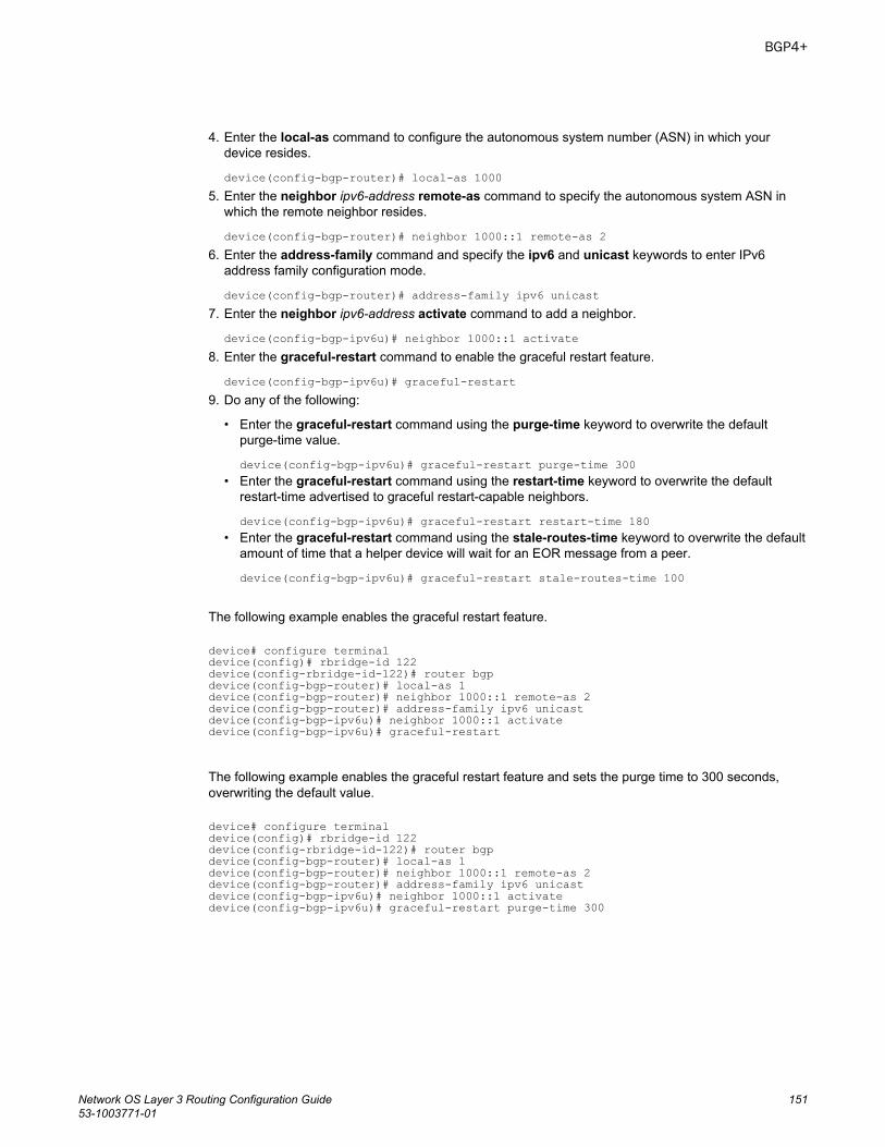
4. Enter the local-as command to configure the autonomous system number (ASN) in which yourdevice resides.
device(config-bgp-router)# local-as 10005. Enter the neighbor ipv6-address remote-as command to specify the autonomous system ASN in
which the remote neighbor resides.
device(config-bgp-router)# neighbor 1000::1 remote-as 26. Enter the address-family command and specify the ipv6 and unicast keywords to enter IPv6
address family configuration mode.
device(config-bgp-router)# address-family ipv6 unicast7. Enter the neighbor ipv6-address activate command to add a neighbor.
device(config-bgp-ipv6u)# neighbor 1000::1 activate8. Enter the graceful-restart command to enable the graceful restart feature.
device(config-bgp-ipv6u)# graceful-restart9. Do any of the following:
• Enter the graceful-restart command using the purge-time keyword to overwrite the defaultpurge-time value.
device(config-bgp-ipv6u)# graceful-restart purge-time 300• Enter the graceful-restart command using the restart-time keyword to overwrite the default
restart-time advertised to graceful restart-capable neighbors.
device(config-bgp-ipv6u)# graceful-restart restart-time 180• Enter the graceful-restart command using the stale-routes-time keyword to overwrite the default
amount of time that a helper device will wait for an EOR message from a peer.
device(config-bgp-ipv6u)# graceful-restart stale-routes-time 100
The following example enables the graceful restart feature.
device# configure terminaldevice(config)# rbridge-id 122device(config-rbridge-id-122)# router bgpdevice(config-bgp-router)# local-as 1device(config-bgp-router)# neighbor 1000::1 remote-as 2device(config-bgp-router)# address-family ipv6 unicastdevice(config-bgp-ipv6u)# neighbor 1000::1 activatedevice(config-bgp-ipv6u)# graceful-restart
The following example enables the graceful restart feature and sets the purge time to 300 seconds,overwriting the default value.
device# configure terminaldevice(config)# rbridge-id 122device(config-rbridge-id-122)# router bgpdevice(config-bgp-router)# local-as 1device(config-bgp-router)# neighbor 1000::1 remote-as 2device(config-bgp-router)# address-family ipv6 unicastdevice(config-bgp-ipv6u)# neighbor 1000::1 activatedevice(config-bgp-ipv6u)# graceful-restart purge-time 300
BGP4+
Network OS Layer 3 Routing Configuration Guide 15153-1003771-01
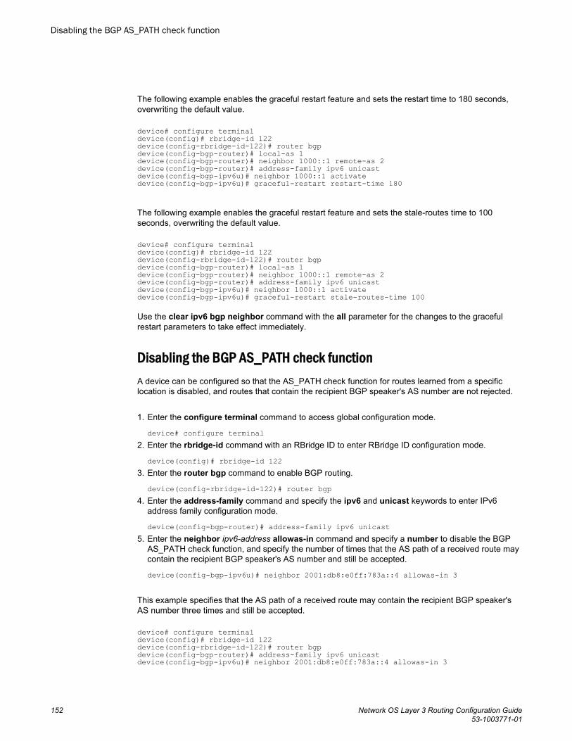
The following example enables the graceful restart feature and sets the restart time to 180 seconds,overwriting the default value.
device# configure terminaldevice(config)# rbridge-id 122device(config-rbridge-id-122)# router bgpdevice(config-bgp-router)# local-as 1device(config-bgp-router)# neighbor 1000::1 remote-as 2device(config-bgp-router)# address-family ipv6 unicastdevice(config-bgp-ipv6u)# neighbor 1000::1 activatedevice(config-bgp-ipv6u)# graceful-restart restart-time 180
The following example enables the graceful restart feature and sets the stale-routes time to 100seconds, overwriting the default value.
device# configure terminaldevice(config)# rbridge-id 122device(config-rbridge-id-122)# router bgpdevice(config-bgp-router)# local-as 1device(config-bgp-router)# neighbor 1000::1 remote-as 2device(config-bgp-router)# address-family ipv6 unicastdevice(config-bgp-ipv6u)# neighbor 1000::1 activatedevice(config-bgp-ipv6u)# graceful-restart stale-routes-time 100
Use the clear ipv6 bgp neighbor command with the all parameter for the changes to the gracefulrestart parameters to take effect immediately.
Disabling the BGP AS_PATH check functionA device can be configured so that the AS_PATH check function for routes learned from a specificlocation is disabled, and routes that contain the recipient BGP speaker's AS number are not rejected.
1. Enter the configure terminal command to access global configuration mode.
device# configure terminal2. Enter the rbridge-id command with an RBridge ID to enter RBridge ID configuration mode.
device(config)# rbridge-id 1223. Enter the router bgp command to enable BGP routing.
device(config-rbridge-id-122)# router bgp4. Enter the address-family command and specify the ipv6 and unicast keywords to enter IPv6
address family configuration mode.
device(config-bgp-router)# address-family ipv6 unicast5. Enter the neighbor ipv6-address allowas-in command and specify a number to disable the BGP
AS_PATH check function, and specify the number of times that the AS path of a received route maycontain the recipient BGP speaker's AS number and still be accepted.
device(config-bgp-ipv6u)# neighbor 2001:db8:e0ff:783a::4 allowas-in 3
This example specifies that the AS path of a received route may contain the recipient BGP speaker'sAS number three times and still be accepted.
device# configure terminaldevice(config)# rbridge-id 122device(config-rbridge-id-122)# router bgpdevice(config-bgp-router)# address-family ipv6 unicastdevice(config-bgp-ipv6u)# neighbor 2001:db8:e0ff:783a::4 allowas-in 3
Disabling the BGP AS_PATH check function
152 Network OS Layer 3 Routing Configuration Guide53-1003771-01
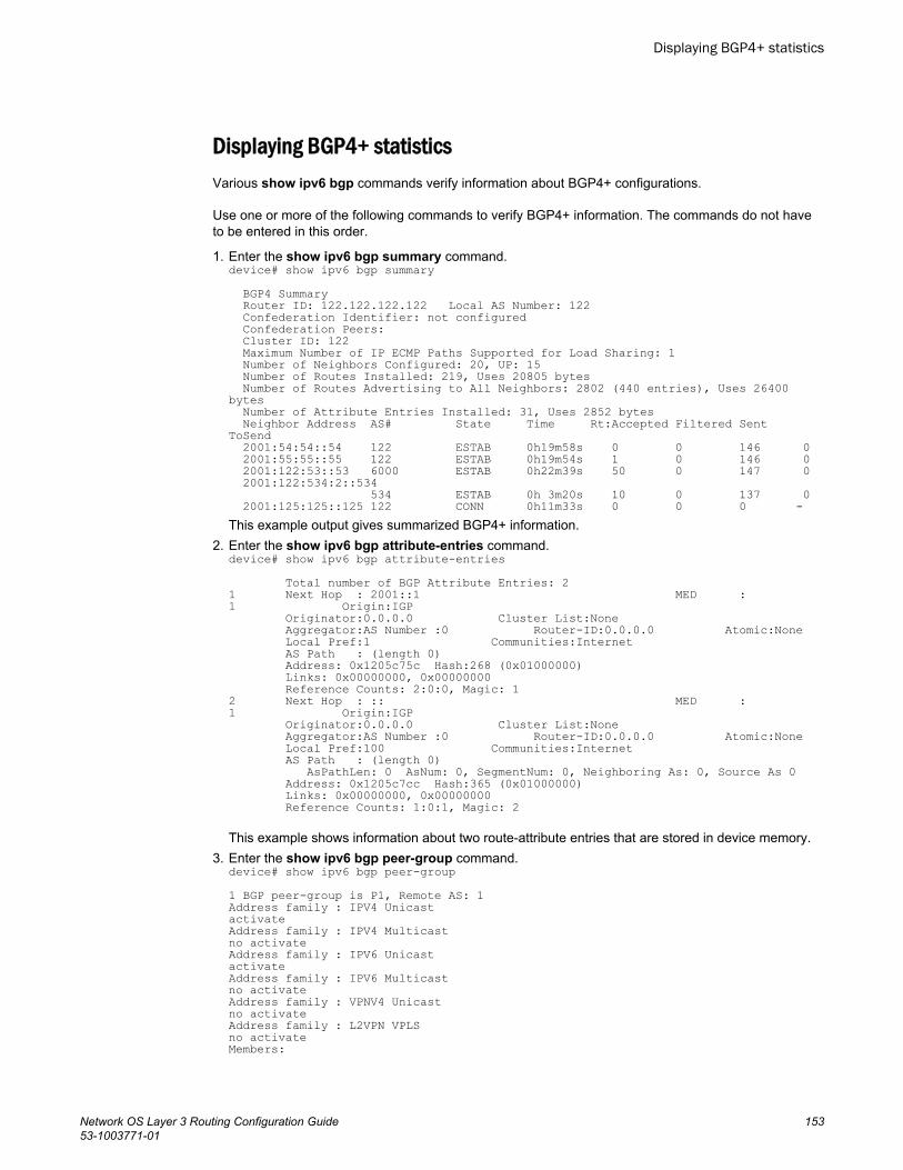
Displaying BGP4+ statisticsVarious show ipv6 bgp commands verify information about BGP4+ configurations.
Use one or more of the following commands to verify BGP4+ information. The commands do not haveto be entered in this order.
1. Enter the show ipv6 bgp summary command.device# show ipv6 bgp summary BGP4 Summary Router ID: 122.122.122.122 Local AS Number: 122 Confederation Identifier: not configured Confederation Peers: Cluster ID: 122 Maximum Number of IP ECMP Paths Supported for Load Sharing: 1 Number of Neighbors Configured: 20, UP: 15 Number of Routes Installed: 219, Uses 20805 bytes Number of Routes Advertising to All Neighbors: 2802 (440 entries), Uses 26400 bytes Number of Attribute Entries Installed: 31, Uses 2852 bytes Neighbor Address AS# State Time Rt:Accepted Filtered Sent ToSend 2001:54:54::54 122 ESTAB 0h19m58s 0 0 146 0 2001:55:55::55 122 ESTAB 0h19m54s 1 0 146 0 2001:122:53::53 6000 ESTAB 0h22m39s 50 0 147 0 2001:122:534:2::534 534 ESTAB 0h 3m20s 10 0 137 0 2001:125:125::125 122 CONN 0h11m33s 0 0 0 -This example output gives summarized BGP4+ information.
2. Enter the show ipv6 bgp attribute-entries command.device# show ipv6 bgp attribute-entries Total number of BGP Attribute Entries: 21 Next Hop : 2001::1 MED :1 Origin:IGP Originator:0.0.0.0 Cluster List:None Aggregator:AS Number :0 Router-ID:0.0.0.0 Atomic:None Local Pref:1 Communities:Internet AS Path : (length 0) Address: 0x1205c75c Hash:268 (0x01000000) Links: 0x00000000, 0x00000000 Reference Counts: 2:0:0, Magic: 12 Next Hop : :: MED :1 Origin:IGP Originator:0.0.0.0 Cluster List:None Aggregator:AS Number :0 Router-ID:0.0.0.0 Atomic:None Local Pref:100 Communities:Internet AS Path : (length 0) AsPathLen: 0 AsNum: 0, SegmentNum: 0, Neighboring As: 0, Source As 0 Address: 0x1205c7cc Hash:365 (0x01000000) Links: 0x00000000, 0x00000000 Reference Counts: 1:0:1, Magic: 2
This example shows information about two route-attribute entries that are stored in device memory.3. Enter the show ipv6 bgp peer-group command.
device# show ipv6 bgp peer-group1 BGP peer-group is P1, Remote AS: 1Address family : IPV4 UnicastactivateAddress family : IPV4 Multicastno activateAddress family : IPV6 UnicastactivateAddress family : IPV6 Multicastno activateAddress family : VPNV4 Unicastno activateAddress family : L2VPN VPLSno activateMembers:
Displaying BGP4+ statistics
Network OS Layer 3 Routing Configuration Guide 15353-1003771-01
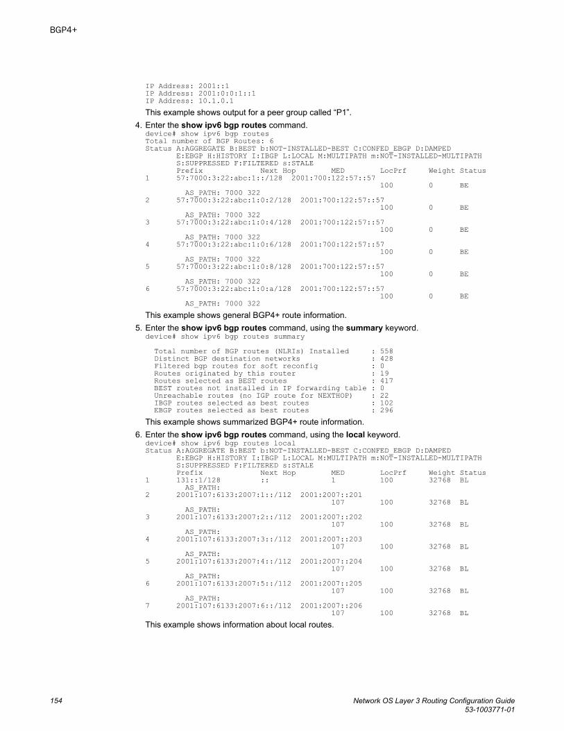
IP Address: 2001::1IP Address: 2001:0:0:1::1IP Address: 10.1.0.1This example shows output for a peer group called “P1”.
4. Enter the show ipv6 bgp routes command.device# show ipv6 bgp routesTotal number of BGP Routes: 6Status A:AGGREGATE B:BEST b:NOT-INSTALLED-BEST C:CONFED_EBGP D:DAMPED E:EBGP H:HISTORY I:IBGP L:LOCAL M:MULTIPATH m:NOT-INSTALLED-MULTIPATH S:SUPPRESSED F:FILTERED s:STALE Prefix Next Hop MED LocPrf Weight Status1 57:7000:3:22:abc:1::/128 2001:700:122:57::57 100 0 BE AS_PATH: 7000 3222 57:7000:3:22:abc:1:0:2/128 2001:700:122:57::57 100 0 BE AS_PATH: 7000 3223 57:7000:3:22:abc:1:0:4/128 2001:700:122:57::57 100 0 BE AS_PATH: 7000 3224 57:7000:3:22:abc:1:0:6/128 2001:700:122:57::57 100 0 BE AS_PATH: 7000 3225 57:7000:3:22:abc:1:0:8/128 2001:700:122:57::57 100 0 BE AS_PATH: 7000 3226 57:7000:3:22:abc:1:0:a/128 2001:700:122:57::57 100 0 BE AS_PATH: 7000 322This example shows general BGP4+ route information.
5. Enter the show ipv6 bgp routes command, using the summary keyword.device# show ipv6 bgp routes summary Total number of BGP routes (NLRIs) Installed : 558 Distinct BGP destination networks : 428 Filtered bgp routes for soft reconfig : 0 Routes originated by this router : 19 Routes selected as BEST routes : 417 BEST routes not installed in IP forwarding table : 0 Unreachable routes (no IGP route for NEXTHOP) : 22 IBGP routes selected as best routes : 102 EBGP routes selected as best routes : 296This example shows summarized BGP4+ route information.
6. Enter the show ipv6 bgp routes command, using the local keyword.device# show ipv6 bgp routes local Status A:AGGREGATE B:BEST b:NOT-INSTALLED-BEST C:CONFED_EBGP D:DAMPED E:EBGP H:HISTORY I:IBGP L:LOCAL M:MULTIPATH m:NOT-INSTALLED-MULTIPATH S:SUPPRESSED F:FILTERED s:STALE Prefix Next Hop MED LocPrf Weight Status1 131::1/128 :: 1 100 32768 BL AS_PATH:2 2001:107:6133:2007:1::/112 2001:2007::201 107 100 32768 BL AS_PATH:3 2001:107:6133:2007:2::/112 2001:2007::202 107 100 32768 BL AS_PATH:4 2001:107:6133:2007:3::/112 2001:2007::203 107 100 32768 BL AS_PATH:5 2001:107:6133:2007:4::/112 2001:2007::204 107 100 32768 BL AS_PATH:6 2001:107:6133:2007:5::/112 2001:2007::205 107 100 32768 BL AS_PATH:7 2001:107:6133:2007:6::/112 2001:2007::206 107 100 32768 BLThis example shows information about local routes.
BGP4+
154 Network OS Layer 3 Routing Configuration Guide53-1003771-01
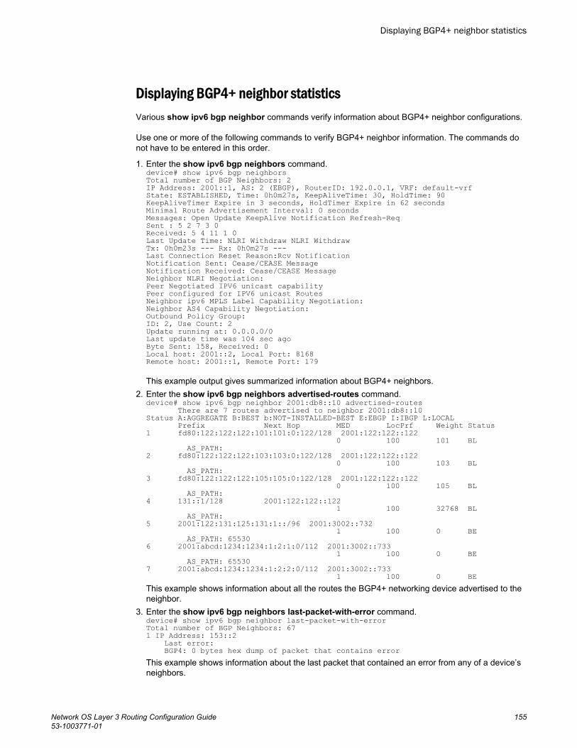
Displaying BGP4+ neighbor statisticsVarious show ipv6 bgp neighbor commands verify information about BGP4+ neighbor configurations.
Use one or more of the following commands to verify BGP4+ neighbor information. The commands donot have to be entered in this order.
1. Enter the show ipv6 bgp neighbors command.device# show ipv6 bgp neighborsTotal number of BGP Neighbors: 2IP Address: 2001::1, AS: 2 (EBGP), RouterID: 192.0.0.1, VRF: default-vrfState: ESTABLISHED, Time: 0h0m27s, KeepAliveTime: 30, HoldTime: 90KeepAliveTimer Expire in 3 seconds, HoldTimer Expire in 62 secondsMinimal Route Advertisement Interval: 0 secondsMessages: Open Update KeepAlive Notification Refresh-ReqSent : 5 2 7 3 0Received: 5 4 11 1 0Last Update Time: NLRI Withdraw NLRI WithdrawTx: 0h0m23s --- Rx: 0h0m27s ---Last Connection Reset Reason:Rcv NotificationNotification Sent: Cease/CEASE MessageNotification Received: Cease/CEASE MessageNeighbor NLRI Negotiation:Peer Negotiated IPV6 unicast capabilityPeer configured for IPV6 unicast RoutesNeighbor ipv6 MPLS Label Capability Negotiation:Neighbor AS4 Capability Negotiation:Outbound Policy Group:ID: 2, Use Count: 2Update running at: 0.0.0.0/0Last update time was 104 sec agoByte Sent: 158, Received: 0Local host: 2001::2, Local Port: 8168Remote host: 2001::1, Remote Port: 179
This example output gives summarized information about BGP4+ neighbors.2. Enter the show ipv6 bgp neighbors advertised-routes command.
device# show ipv6 bgp neighbor 2001:db8::10 advertised-routes There are 7 routes advertised to neighbor 2001:db8::10Status A:AGGREGATE B:BEST b:NOT-INSTALLED-BEST E:EBGP I:IBGP L:LOCAL Prefix Next Hop MED LocPrf Weight Status1 fd80:122:122:122:101:101:0:122/128 2001:122:122::122 0 100 101 BL AS_PATH:2 fd80:122:122:122:103:103:0:122/128 2001:122:122::122 0 100 103 BL AS_PATH:3 fd80:122:122:122:105:105:0:122/128 2001:122:122::122 0 100 105 BL AS_PATH:4 131::1/128 2001:122:122::122 1 100 32768 BL AS_PATH:5 2001:122:131:125:131:1::/96 2001:3002::732 1 100 0 BE AS_PATH: 655306 2001:abcd:1234:1234:1:2:1:0/112 2001:3002::733 1 100 0 BE AS_PATH: 655307 2001:abcd:1234:1234:1:2:2:0/112 2001:3002::733 1 100 0 BEThis example shows information about all the routes the BGP4+ networking device advertised to theneighbor.
3. Enter the show ipv6 bgp neighbors last-packet-with-error command.device# show ipv6 bgp neighbor last-packet-with-errorTotal number of BGP Neighbors: 671 IP Address: 153::2 Last error: BGP4: 0 bytes hex dump of packet that contains errorThis example shows information about the last packet that contained an error from any of a device’sneighbors.
Displaying BGP4+ neighbor statistics
Network OS Layer 3 Routing Configuration Guide 15553-1003771-01
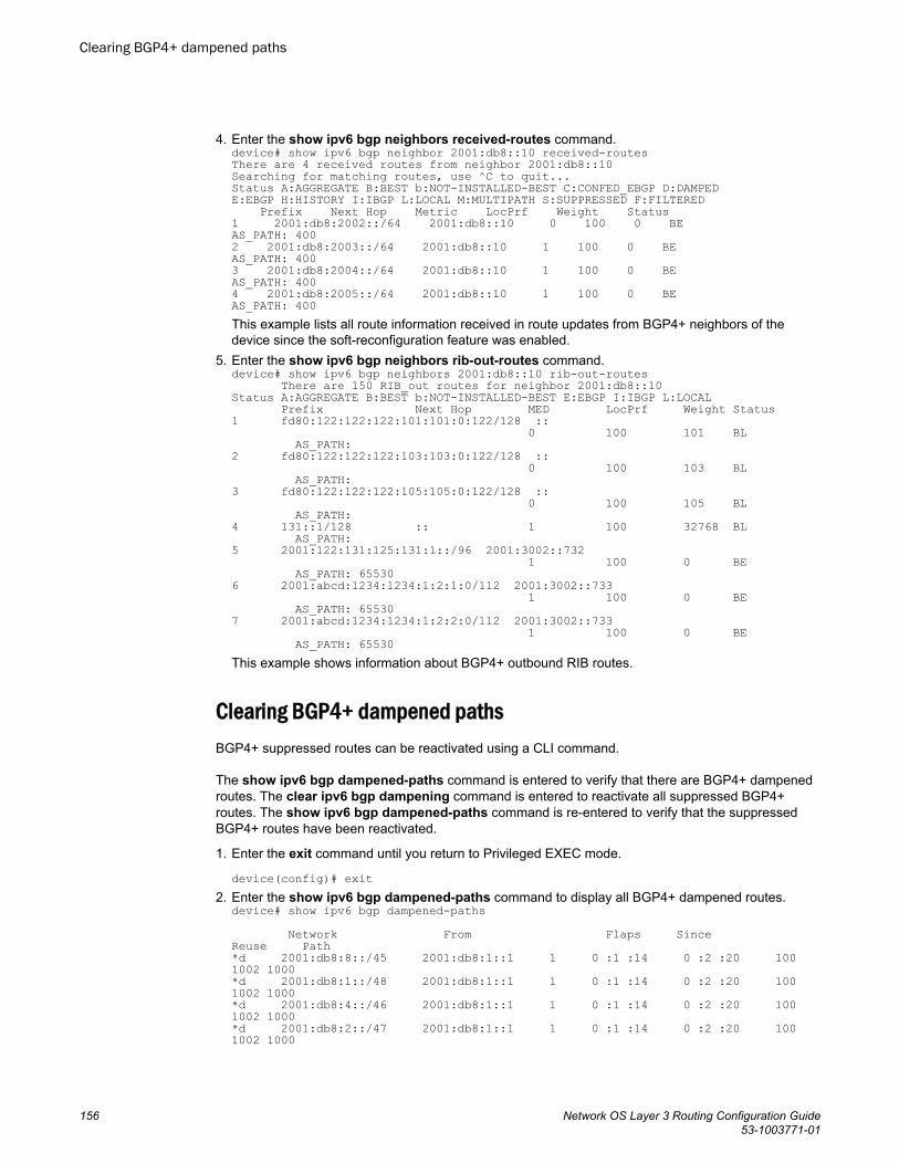
4. Enter the show ipv6 bgp neighbors received-routes command.device# show ipv6 bgp neighbor 2001:db8::10 received-routesThere are 4 received routes from neighbor 2001:db8::10Searching for matching routes, use ^C to quit...Status A:AGGREGATE B:BEST b:NOT-INSTALLED-BEST C:CONFED_EBGP D:DAMPEDE:EBGP H:HISTORY I:IBGP L:LOCAL M:MULTIPATH S:SUPPRESSED F:FILTERED Prefix Next Hop Metric LocPrf Weight Status1 2001:db8:2002::/64 2001:db8::10 0 100 0 BEAS_PATH: 4002 2001:db8:2003::/64 2001:db8::10 1 100 0 BEAS_PATH: 4003 2001:db8:2004::/64 2001:db8::10 1 100 0 BEAS_PATH: 4004 2001:db8:2005::/64 2001:db8::10 1 100 0 BEAS_PATH: 400This example lists all route information received in route updates from BGP4+ neighbors of thedevice since the soft-reconfiguration feature was enabled.
5. Enter the show ipv6 bgp neighbors rib-out-routes command.device# show ipv6 bgp neighbors 2001:db8::10 rib-out-routes There are 150 RIB_out routes for neighbor 2001:db8::10Status A:AGGREGATE B:BEST b:NOT-INSTALLED-BEST E:EBGP I:IBGP L:LOCAL Prefix Next Hop MED LocPrf Weight Status1 fd80:122:122:122:101:101:0:122/128 :: 0 100 101 BL AS_PATH:2 fd80:122:122:122:103:103:0:122/128 :: 0 100 103 BL AS_PATH:3 fd80:122:122:122:105:105:0:122/128 :: 0 100 105 BL AS_PATH:4 131::1/128 :: 1 100 32768 BL AS_PATH:5 2001:122:131:125:131:1::/96 2001:3002::732 1 100 0 BE AS_PATH: 655306 2001:abcd:1234:1234:1:2:1:0/112 2001:3002::733 1 100 0 BE AS_PATH: 655307 2001:abcd:1234:1234:1:2:2:0/112 2001:3002::733 1 100 0 BE AS_PATH: 65530This example shows information about BGP4+ outbound RIB routes.
Clearing BGP4+ dampened pathsBGP4+ suppressed routes can be reactivated using a CLI command.
The show ipv6 bgp dampened-paths command is entered to verify that there are BGP4+ dampenedroutes. The clear ipv6 bgp dampening command is entered to reactivate all suppressed BGP4+routes. The show ipv6 bgp dampened-paths command is re-entered to verify that the suppressedBGP4+ routes have been reactivated.
1. Enter the exit command until you return to Privileged EXEC mode.
device(config)# exit2. Enter the show ipv6 bgp dampened-paths command to display all BGP4+ dampened routes.
device# show ipv6 bgp dampened-paths Network From Flaps Since Reuse Path*d 2001:db8:8::/45 2001:db8:1::1 1 0 :1 :14 0 :2 :20 100 1002 1000*d 2001:db8:1::/48 2001:db8:1::1 1 0 :1 :14 0 :2 :20 100 1002 1000*d 2001:db8:4::/46 2001:db8:1::1 1 0 :1 :14 0 :2 :20 100 1002 1000*d 2001:db8:2::/47 2001:db8:1::1 1 0 :1 :14 0 :2 :20 100 1002 1000
Clearing BGP4+ dampened paths
156 Network OS Layer 3 Routing Configuration Guide53-1003771-01
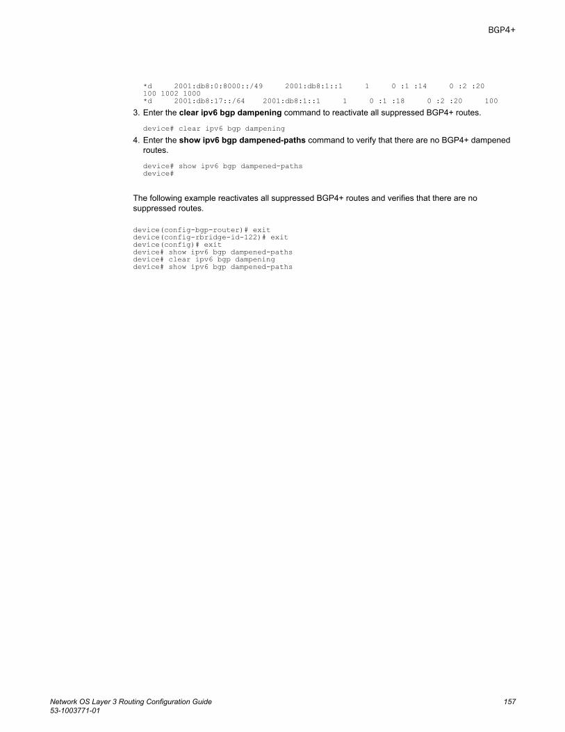
*d 2001:db8:0:8000::/49 2001:db8:1::1 1 0 :1 :14 0 :2 :20 100 1002 1000*d 2001:db8:17::/64 2001:db8:1::1 1 0 :1 :18 0 :2 :20 100
3. Enter the clear ipv6 bgp dampening command to reactivate all suppressed BGP4+ routes.
device# clear ipv6 bgp dampening4. Enter the show ipv6 bgp dampened-paths command to verify that there are no BGP4+ dampened
routes.
device# show ipv6 bgp dampened-pathsdevice#
The following example reactivates all suppressed BGP4+ routes and verifies that there are nosuppressed routes.
device(config-bgp-router)# exitdevice(config-rbridge-id-122)# exitdevice(config)# exitdevice# show ipv6 bgp dampened-pathsdevice# clear ipv6 bgp dampeningdevice# show ipv6 bgp dampened-paths
BGP4+
Network OS Layer 3 Routing Configuration Guide 15753-1003771-01

Clearing BGP4+ dampened paths
158 Network OS Layer 3 Routing Configuration Guide53-1003771-01
VRRP
● VRRPv2 Overview........................................................................................................ 159● Enabling a master VRRP device...................................................................................164● Enabling a backup VRRP device.................................................................................. 165● Enabling a VRRP-E device........................................................................................... 166● VRRP multigroup clusters............................................................................................. 167● Track ports and track priority with VRRP and VRRP-E.................................................170● Track routes and track priority with VRRP-E.................................................................172● VRRP backup preemption.............................................................................................173● VRRP-E load-balancing using short-path forwarding....................................................174● Clearing VRRPv2 statistics........................................................................................... 177● Displaying VRRPv2 information.................................................................................... 178
VRRPv2 OverviewVirtual Router Redundancy Protocol (VRRP) is an election protocol that provides redundancy to routerswithin a Local Area Network (LAN).
VRRP was designed to eliminate a single point of failure in a static default-route environment bydynamically assigning virtual IP routers to participating hosts. A virtual router is a collection of physicalrouters where the interfaces must belong to the same IP subnet. A virtual router ID is assigned to eachvirtual router, but there is no restriction against reusing a virtual router ID (VRID) with a differentaddress mapping on different LANs
Before examining more details about how VRRP works, it is useful to see why VRRP was developed tosolve the single point of failure issue.
Network OS Layer 3 Routing Configuration Guide 15953-1003771-01
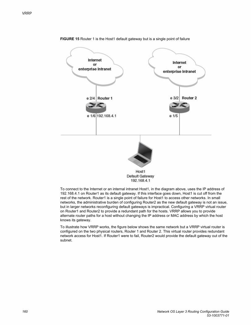
FIGURE 15 Router 1 is the Host1 default gateway but is a single point of failure
To connect to the Internet or an internal intranet Host1, in the diagram above, uses the IP address of192.168.4.1 on Router1 as its default gateway. If this interface goes down, Host1 is cut off from therest of the network. Router1 is a single point of failure for Host1 to access other networks. In smallnetworks, the administrative burden of configuring Router2 as the new default gateway is not an issue,but in larger networks reconfiguring default gateways is impractical. Configuring a VRRP virtual routeron Router1 and Router2 to provide a redundant path for the hosts. VRRP allows you to providealternate router paths for a host without changing the IP address or MAC address by which the hostknows its gateway.
To illustrate how VRRP works, the figure below shows the same network but a VRRP virtual router isconfigured on the two physical routers, Router 1 and Router 2. This virtual router provides redundantnetwork access for Host1. If Router1 were to fail, Router2 would provide the default gateway out of thesubnet.
VRRP
160 Network OS Layer 3 Routing Configuration Guide53-1003771-01
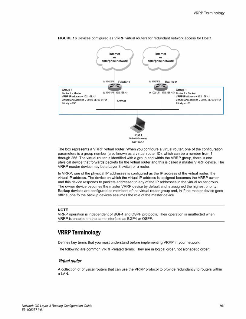
FIGURE 16 Devices configured as VRRP virtual routers for redundant network access for Host1
The box represents a VRRP virtual router. When you configure a virtual router, one of the configurationparameters is a group number (also known as a virtual router ID), which can be a number from 1through 255. The virtual router is identified with a group and within the VRRP group, there is onephysical device that forwards packets for the virtual router and this is called a master VRRP device. TheVRRP master device may be a Layer 3 switch or a router.
In VRRP, one of the physical IP addresses is configured as the IP address of the virtual router, thevirtual IP address. The device on which the virtual IP address is assigned becomes the VRRP ownerand this device responds to packets addressed to any of the IP addresses in the virtual router group.The owner device becomes the master VRRP device by default and is assigned the highest priority.Backup devices are configured as members of the virtual router group and, in if the master device goesoffline, one fo the backup devices assumes the role of the master device.
NOTEVRRP operation is independent of BGP4 and OSPF protocols. Their operation is unaffected whenVRRP is enabled on the same interface as BGP4 or OSPF.
VRRP TerminologyDefines key terms that you must understand before implementing VRRP in your network.
The following are common VRRP-related terms. They are in logical order, not alphabetic order:
Virtual routerA collection of physical routers that can use the VRRP protocol to provide redundancy to routers withina LAN.
VRRP Terminology
Network OS Layer 3 Routing Configuration Guide 16153-1003771-01
Virtual router groupA group of physical routers that are assigned to the same virtual router.
Virtual router addressThe virtual router IP address must belong to the same subnet as a real IP address configured on theVRRP interface, and can be the same as a real IP addresses configured on the VRRP interface. Thevirtual router whose virtual IP address is the same as a real IP address is the IP address owner andthe default master.
OwnerThe owner is the physical router whose real interface IP address is the IP address that you assign tothe virtual router. The owner responds to packets addressed to any of the IP addresses in thecorresponding virtual router. The owner, by default, is the master and has the highest priority (255).
MasterThe physical router that responds to packets addressed to any of the IP addresses in thecorresponding virtual router. For VRRP, if the physical router whose real interface IP address is the IPaddress of the virtual router, then this physical router is always the master.
BackupRouters that belong to a virtual router, but are not the master. Then, if the master becomesunavailable, the backup router with the highest priority (a configurable value) becomes the newmaster. By default, routers are given a priority of 100.
VRRP-Ev2 overviewVRRP extended (VRRP-E) is an extended version of the VRRP protocol. VRRP-E is designed to avoidthe limitations in the standards-based VRRP.
To create VRRP-E, Brocade has implemented the following differences from the RFC 3768 thatdescribes VRRPv2 to provide extended functionality and ease of configuration:
• VRRP-E does not include the concept of an owner device and a master VRRP-E is determined bythe priority configured on the device.
• While the VRRP-E virtual router IP address must belong in the same subnet as a real IP addressassigned to a physical interface of the device on which VRRP-E is configured, it must not be thesame as any of the actual IP addresses on any interface.
• Configuring VRRP-E uses the same task steps for all devices; no differences between master andbackup device configuration. The device configured with the highest priority assumes the masterrole.
VRRP-E is not supported on non-Brocade devices and does not interoperate with VRRP sessions onBrocade devices.
VRRPv2 limitations on Brocade VDX devicesThe implementation of VRRPv2 varies across the VDX products.
Virtual routers must be configured in a Virtual Cluster Switching (VCS) environment.
VRRP-Ev2 overview
162 Network OS Layer 3 Routing Configuration Guide53-1003771-01
Only IPv4 support is provided in VRRPv2. VRRPv3 supports both IPv4 and IPv6.
Supported ports:
• For VRRP—fortygigabitethernet, tengigabitethernet, gigabitethernet, and ve• For VRRP-E—ve ports only
System Resource VDX 87xx VDX 6740, 6740T, 6740T-1GT, 6940-36Q
Max # of VRRP and VRRP-E sessions 1024 255
The maximum number of virtual IP addresses per virtual router session is 16 for VRRP, and one forVRRP-E.
VRRP hold timerHold timer support delays the preemption of a master VRRP device by a high-priority backup device.
A hold timer is used when a VRRP-enabled device that was previously a master device failed, but isnow back up. This restored device now has a higher priority than the current VRRP master device andVRRP normally triggers an immediate switchover. In this situation, it is possible that not all the softwarecomponents on the backup device have converged yet. The hold timer can enforce a waiting periodbefore the higher-priority backup device assumes the role of master VRRP device again. The timermust be set to a number greater than 0 seconds for this functionality to take effect.
Hold timer functionality is supported in both version 2 and version 3 of VRRP and VRRP-E.
VRRP interval timersTimers for the intervals between hello messages between devices running VRRP can be configured.
hello intervalsHello messages are sent from the master VRRP device to the backup devices. The purpose of the hellomessages is to that the master device is still online. If the backup devices stop receiving the hellomessages for a period of time, as defined by the dead interval, the backup devices assume the masterdevice is offline. When the master device is offline, the backup device with the highest priority assumesthe role of the master device.
backup hello message state and intervalBy default, backup devices do not send hello messages to advertise themselves to the master device.Hello messages from backup devices can be activated and the messages are sent at 60 secondintervals, by default. The interval between the backup hello messages can be modified.
ARP and VRRP control packetsControl packets for ARP and VRRP are handled differently by VRRP and VRRP-E.
Source MAC addresses in VRRP control packets• VRRP—The virtual MAC address is the source.• VRRP-E—The physical MAC address is the source.
VRRP hold timer
Network OS Layer 3 Routing Configuration Guide 16353-1003771-01
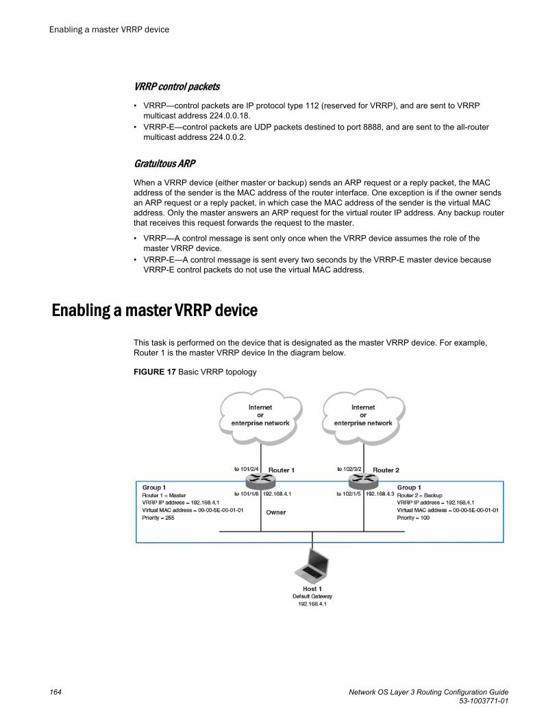
VRRP control packets• VRRP—control packets are IP protocol type 112 (reserved for VRRP), and are sent to VRRP
multicast address 224.0.0.18.• VRRP-E—control packets are UDP packets destined to port 8888, and are sent to the all-router
multicast address 224.0.0.2.
Gratuitous ARPWhen a VRRP device (either master or backup) sends an ARP request or a reply packet, the MACaddress of the sender is the MAC address of the router interface. One exception is if the owner sendsan ARP request or a reply packet, in which case the MAC address of the sender is the virtual MACaddress. Only the master answers an ARP request for the virtual router IP address. Any backup routerthat receives this request forwards the request to the master.
• VRRP—A control message is sent only once when the VRRP device assumes the role of themaster VRRP device.
• VRRP-E—A control message is sent every two seconds by the VRRP-E master device becauseVRRP-E control packets do not use the virtual MAC address.
Enabling a master VRRP device
This task is performed on the device that is designated as the master VRRP device. For example,Router 1 is the master VRRP device In the diagram below.
FIGURE 17 Basic VRRP topology
Enabling a master VRRP device
164 Network OS Layer 3 Routing Configuration Guide53-1003771-01
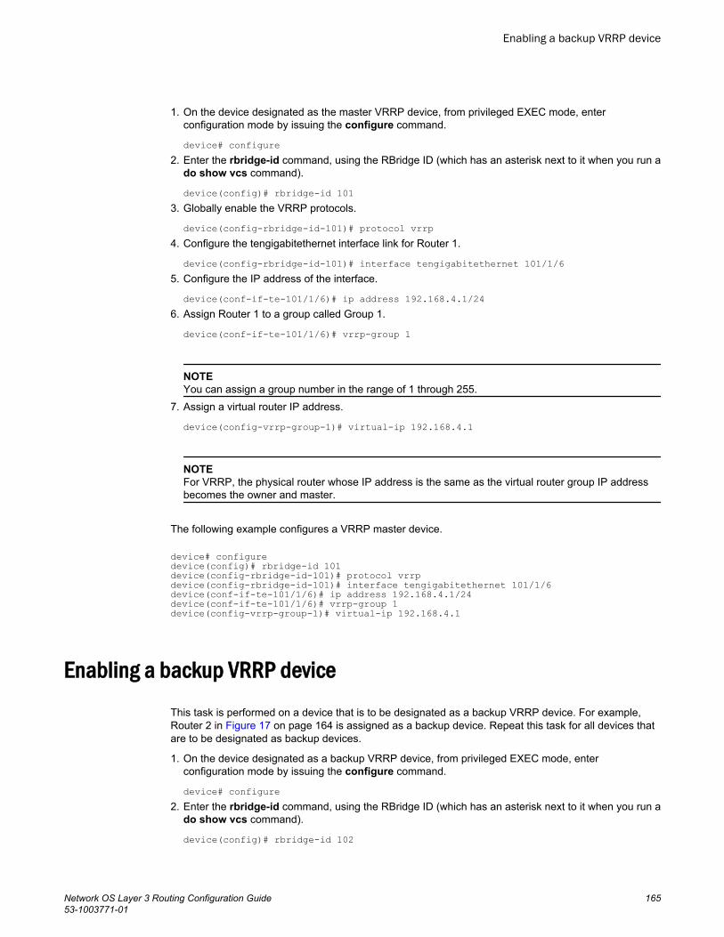
1. On the device designated as the master VRRP device, from privileged EXEC mode, enterconfiguration mode by issuing the configure command.
device# configure2. Enter the rbridge-id command, using the RBridge ID (which has an asterisk next to it when you run a
do show vcs command).
device(config)# rbridge-id 1013. Globally enable the VRRP protocols.
device(config-rbridge-id-101)# protocol vrrp4. Configure the tengigabitethernet interface link for Router 1.
device(config-rbridge-id-101)# interface tengigabitethernet 101/1/65. Configure the IP address of the interface.
device(conf-if-te-101/1/6)# ip address 192.168.4.1/246. Assign Router 1 to a group called Group 1.
device(conf-if-te-101/1/6)# vrrp-group 1
NOTEYou can assign a group number in the range of 1 through 255.
7. Assign a virtual router IP address.
device(config-vrrp-group-1)# virtual-ip 192.168.4.1
NOTEFor VRRP, the physical router whose IP address is the same as the virtual router group IP addressbecomes the owner and master.
The following example configures a VRRP master device.
device# configuredevice(config)# rbridge-id 101device(config-rbridge-id-101)# protocol vrrpdevice(config-rbridge-id-101)# interface tengigabitethernet 101/1/6device(conf-if-te-101/1/6)# ip address 192.168.4.1/24device(conf-if-te-101/1/6)# vrrp-group 1device(config-vrrp-group-1)# virtual-ip 192.168.4.1
Enabling a backup VRRP device
This task is performed on a device that is to be designated as a backup VRRP device. For example,Router 2 in Figure 17 on page 164 is assigned as a backup device. Repeat this task for all devices thatare to be designated as backup devices.
1. On the device designated as a backup VRRP device, from privileged EXEC mode, enterconfiguration mode by issuing the configure command.
device# configure2. Enter the rbridge-id command, using the RBridge ID (which has an asterisk next to it when you run a
do show vcs command).
device(config)# rbridge-id 102
Enabling a backup VRRP device
Network OS Layer 3 Routing Configuration Guide 16553-1003771-01
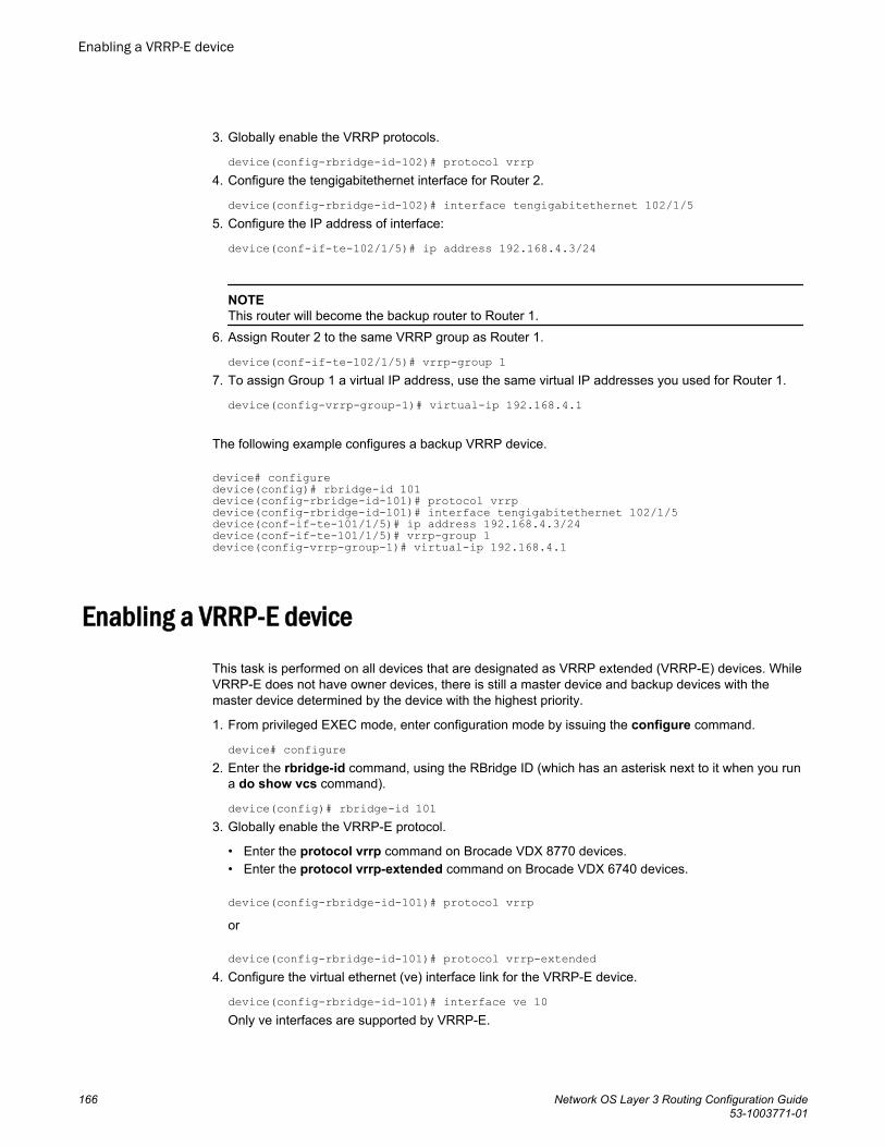
3. Globally enable the VRRP protocols.
device(config-rbridge-id-102)# protocol vrrp4. Configure the tengigabitethernet interface for Router 2.
device(config-rbridge-id-102)# interface tengigabitethernet 102/1/5 5. Configure the IP address of interface:
device(conf-if-te-102/1/5)# ip address 192.168.4.3/24
NOTEThis router will become the backup router to Router 1.
6. Assign Router 2 to the same VRRP group as Router 1.
device(conf-if-te-102/1/5)# vrrp-group 17. To assign Group 1 a virtual IP address, use the same virtual IP addresses you used for Router 1.
device(config-vrrp-group-1)# virtual-ip 192.168.4.1
The following example configures a backup VRRP device.
device# configuredevice(config)# rbridge-id 101device(config-rbridge-id-101)# protocol vrrpdevice(config-rbridge-id-101)# interface tengigabitethernet 102/1/5device(conf-if-te-101/1/5)# ip address 192.168.4.3/24device(conf-if-te-101/1/5)# vrrp-group 1device(config-vrrp-group-1)# virtual-ip 192.168.4.1
Enabling a VRRP-E device
This task is performed on all devices that are designated as VRRP extended (VRRP-E) devices. WhileVRRP-E does not have owner devices, there is still a master device and backup devices with themaster device determined by the device with the highest priority.
1. From privileged EXEC mode, enter configuration mode by issuing the configure command.
device# configure2. Enter the rbridge-id command, using the RBridge ID (which has an asterisk next to it when you run
a do show vcs command).
device(config)# rbridge-id 1013. Globally enable the VRRP-E protocol.
• Enter the protocol vrrp command on Brocade VDX 8770 devices.• Enter the protocol vrrp-extended command on Brocade VDX 6740 devices.
device(config-rbridge-id-101)# protocol vrrpor
device(config-rbridge-id-101)# protocol vrrp-extended4. Configure the virtual ethernet (ve) interface link for the VRRP-E device.
device(config-rbridge-id-101)# interface ve 10Only ve interfaces are supported by VRRP-E.
Enabling a VRRP-E device
166 Network OS Layer 3 Routing Configuration Guide53-1003771-01
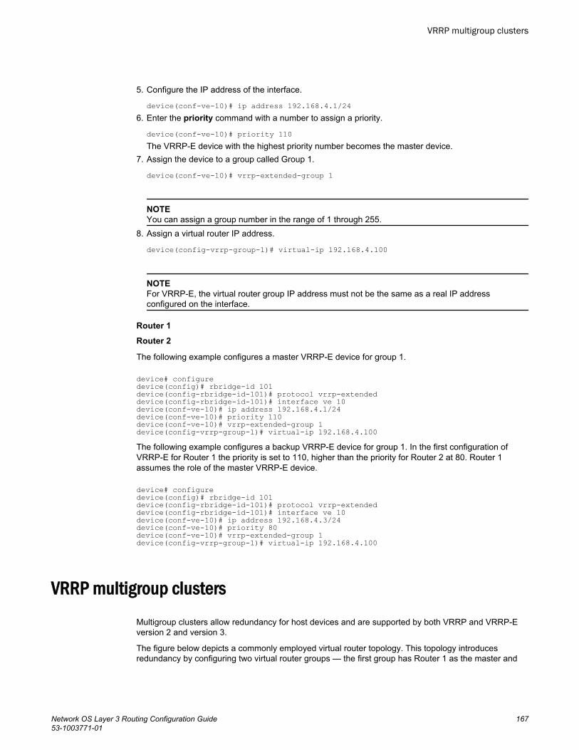
5. Configure the IP address of the interface.
device(conf-ve-10)# ip address 192.168.4.1/246. Enter the priority command with a number to assign a priority.
device(conf-ve-10)# priority 110The VRRP-E device with the highest priority number becomes the master device.
7. Assign the device to a group called Group 1.
device(conf-ve-10)# vrrp-extended-group 1
NOTEYou can assign a group number in the range of 1 through 255.
8. Assign a virtual router IP address.
device(config-vrrp-group-1)# virtual-ip 192.168.4.100
NOTEFor VRRP-E, the virtual router group IP address must not be the same as a real IP addressconfigured on the interface.
Router 1
Router 2
The following example configures a master VRRP-E device for group 1.
device# configuredevice(config)# rbridge-id 101device(config-rbridge-id-101)# protocol vrrp-extendeddevice(config-rbridge-id-101)# interface ve 10device(conf-ve-10)# ip address 192.168.4.1/24device(conf-ve-10)# priority 110device(conf-ve-10)# vrrp-extended-group 1device(config-vrrp-group-1)# virtual-ip 192.168.4.100The following example configures a backup VRRP-E device for group 1. In the first configuration ofVRRP-E for Router 1 the priority is set to 110, higher than the priority for Router 2 at 80. Router 1assumes the role of the master VRRP-E device.
device# configuredevice(config)# rbridge-id 101device(config-rbridge-id-101)# protocol vrrp-extendeddevice(config-rbridge-id-101)# interface ve 10device(conf-ve-10)# ip address 192.168.4.3/24device(conf-ve-10)# priority 80device(conf-ve-10)# vrrp-extended-group 1device(config-vrrp-group-1)# virtual-ip 192.168.4.100
VRRP multigroup clustersMultigroup clusters allow redundancy for host devices and are supported by both VRRP and VRRP-Eversion 2 and version 3.
The figure below depicts a commonly employed virtual router topology. This topology introducesredundancy by configuring two virtual router groups — the first group has Router 1 as the master and
VRRP multigroup clusters
Network OS Layer 3 Routing Configuration Guide 16753-1003771-01
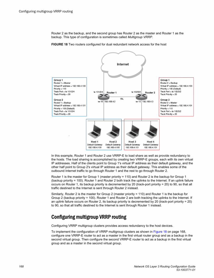
Router 2 as the backup, and the second group has Router 2 as the master and Router 1 as thebackup. This type of configuration is sometimes called Multigroup VRRP.
FIGURE 18 Two routers configured for dual redundant network access for the host
In this example, Router 1 and Router 2 use VRRP-E to load share as well as provide redundancy tothe hosts. The load sharing is accomplished by creating two VRRP-E groups, each with its own virtualIP addresses. Half of the clients point to Group 1's virtual IP address as their default gateway, and theother half point to Group 2's virtual IP address as their default gateway. This enables some of theoutbound Internet traffic to go through Router 1 and the rest to go through Router 2.
Router 1 is the master for Group 1 (master priority = 110) and Router 2 is the backup for Group 1(backup priority = 100). Router 1 and Router 2 both track the uplinks to the Internet. If an uplink failureoccurs on Router 1, its backup priority is decremented by 20 (track-port priority = 20) to 90, so that alltraffic destined to the Internet is sent through Router 2 instead.
Similarly, Router 2 is the master for Group 2 (master priority = 110) and Router 1 is the backup forGroup 2 (backup priority = 100). Router 1 and Router 2 are both tracking the uplinks to the Internet. Ifan uplink failure occurs on Router 2, its backup priority is decremented by 20 (track-port priority = 20)to 90, so that all traffic destined to the Internet is sent through Router 1 instead.
Configuring multigroup VRRP routingConfiguring VRRP multigroup clusters provides access redundancy to the host devices.
To implement the configuration of VRRP multigroup clusters as shown in Figure 18 on page 168,configure one VRRP-E router to act as a master in the first virtual router group and as a backup in thesecond virtual group. Then configure the second VRRP-E router to act as a backup in the first virtualgroup and as a master in the second virtual group.
Configuring multigroup VRRP routing
168 Network OS Layer 3 Routing Configuration Guide53-1003771-01
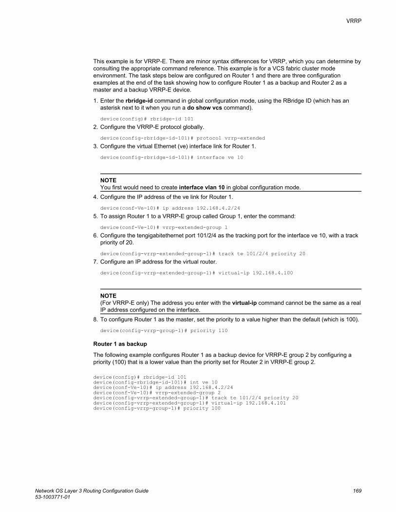
This example is for VRRP-E. There are minor syntax differences for VRRP, which you can determine byconsulting the appropriate command reference. This example is for a VCS fabric cluster modeenvironment. The task steps below are configured on Router 1 and there are three configurationexamples at the end of the task showing how to configure Router 1 as a backup and Router 2 as amaster and a backup VRRP-E device.
1. Enter the rbridge-id command in global configuration mode, using the RBridge ID (which has anasterisk next to it when you run a do show vcs command).
device(config)# rbridge-id 1012. Configure the VRRP-E protocol globally.
device(config-rbridge-id-101)# protocol vrrp-extended3. Configure the virtual Ethernet (ve) interface link for Router 1.
device(config-rbridge-id-101)# interface ve 10
NOTEYou first would need to create interface vlan 10 in global configuration mode.
4. Configure the IP address of the ve link for Router 1.
device(conf-Ve-10)# ip address 192.168.4.2/245. To assign Router 1 to a VRRP-E group called Group 1, enter the command:
device(conf-Ve-10)# vrrp-extended-group 16. Configure the tengigabitethernet port 101/2/4 as the tracking port for the interface ve 10, with a track
priority of 20.
device(config-vrrp-extended-group-1)# track te 101/2/4 priority 207. Configure an IP address for the virtual router.
device(config-vrrp-extended-group-1)# virtual-ip 192.168.4.100
NOTE(For VRRP-E only) The address you enter with the virtual-ip command cannot be the same as a realIP address configured on the interface.
8. To configure Router 1 as the master, set the priority to a value higher than the default (which is 100).
device(config-vrrp-group-1)# priority 110
Router 1 as backup
The following example configures Router 1 as a backup device for VRRP-E group 2 by configuring apriority (100) that is a lower value than the priority set for Router 2 in VRRP-E group 2.
device(config)# rbridge-id 101device(config-rbridge-id-101)# int ve 10device(conf-Ve-10)# ip address 192.168.4.2/24device(conf-Ve-10)# vrrp-extended-group 2device(config-vrrp-extended-group-1)# track te 101/2/4 priority 20device(config-vrrp-extended-group-1)# virtual-ip 192.168.4.101device(config-vrrp-group-1)# priority 100
VRRP
Network OS Layer 3 Routing Configuration Guide 16953-1003771-01
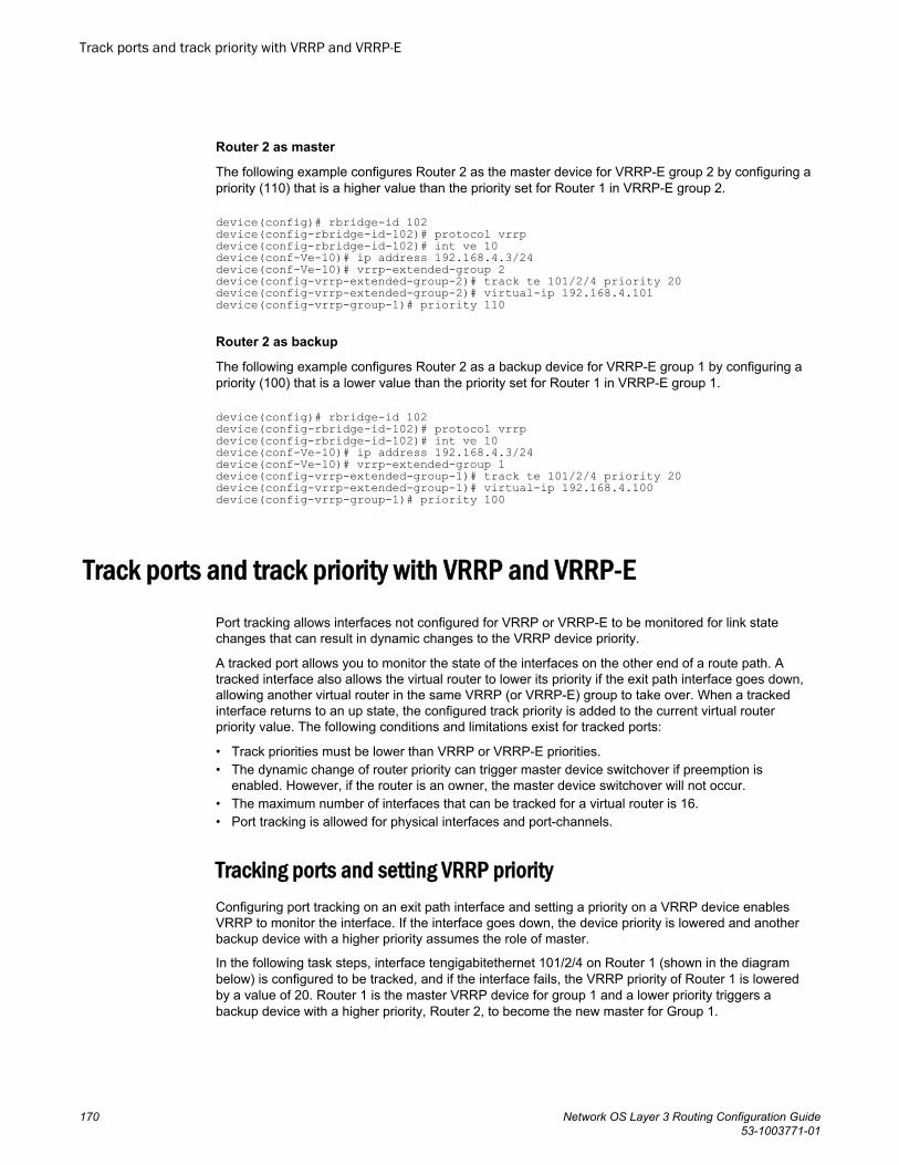
Router 2 as master
The following example configures Router 2 as the master device for VRRP-E group 2 by configuring apriority (110) that is a higher value than the priority set for Router 1 in VRRP-E group 2.
device(config)# rbridge-id 102device(config-rbridge-id-102)# protocol vrrpdevice(config-rbridge-id-102)# int ve 10device(conf-Ve-10)# ip address 192.168.4.3/24device(conf-Ve-10)# vrrp-extended-group 2device(config-vrrp-extended-group-2)# track te 101/2/4 priority 20device(config-vrrp-extended-group-2)# virtual-ip 192.168.4.101device(config-vrrp-group-1)# priority 110
Router 2 as backup
The following example configures Router 2 as a backup device for VRRP-E group 1 by configuring apriority (100) that is a lower value than the priority set for Router 1 in VRRP-E group 1.
device(config)# rbridge-id 102device(config-rbridge-id-102)# protocol vrrpdevice(config-rbridge-id-102)# int ve 10device(conf-Ve-10)# ip address 192.168.4.3/24device(conf-Ve-10)# vrrp-extended-group 1device(config-vrrp-extended-group-1)# track te 101/2/4 priority 20device(config-vrrp-extended-group-1)# virtual-ip 192.168.4.100device(config-vrrp-group-1)# priority 100
Track ports and track priority with VRRP and VRRP-EPort tracking allows interfaces not configured for VRRP or VRRP-E to be monitored for link statechanges that can result in dynamic changes to the VRRP device priority.
A tracked port allows you to monitor the state of the interfaces on the other end of a route path. Atracked interface also allows the virtual router to lower its priority if the exit path interface goes down,allowing another virtual router in the same VRRP (or VRRP-E) group to take over. When a trackedinterface returns to an up state, the configured track priority is added to the current virtual routerpriority value. The following conditions and limitations exist for tracked ports:
• Track priorities must be lower than VRRP or VRRP-E priorities.• The dynamic change of router priority can trigger master device switchover if preemption is
enabled. However, if the router is an owner, the master device switchover will not occur.• The maximum number of interfaces that can be tracked for a virtual router is 16.• Port tracking is allowed for physical interfaces and port-channels.
Tracking ports and setting VRRP priorityConfiguring port tracking on an exit path interface and setting a priority on a VRRP device enablesVRRP to monitor the interface. If the interface goes down, the device priority is lowered and anotherbackup device with a higher priority assumes the role of master.
In the following task steps, interface tengigabitethernet 101/2/4 on Router 1 (shown in the diagrambelow) is configured to be tracked, and if the interface fails, the VRRP priority of Router 1 is loweredby a value of 20. Router 1 is the master VRRP device for group 1 and a lower priority triggers abackup device with a higher priority, Router 2, to become the new master for Group 1.
Track ports and track priority with VRRP and VRRP-E
170 Network OS Layer 3 Routing Configuration Guide53-1003771-01
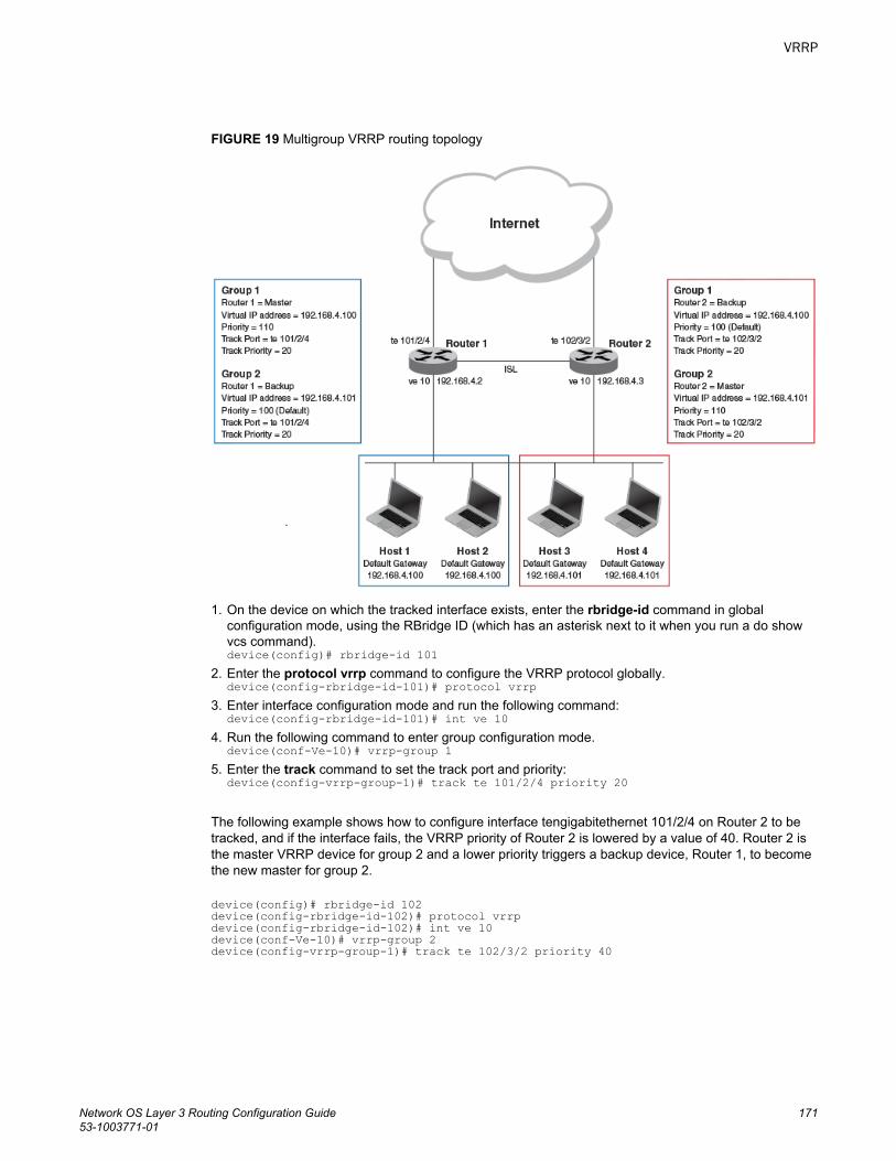
FIGURE 19 Multigroup VRRP routing topology
1. On the device on which the tracked interface exists, enter the rbridge-id command in globalconfiguration mode, using the RBridge ID (which has an asterisk next to it when you run a do showvcs command).device(config)# rbridge-id 101
2. Enter the protocol vrrp command to configure the VRRP protocol globally.device(config-rbridge-id-101)# protocol vrrp
3. Enter interface configuration mode and run the following command:device(config-rbridge-id-101)# int ve 10
4. Run the following command to enter group configuration mode.device(conf-Ve-10)# vrrp-group 1
5. Enter the track command to set the track port and priority:device(config-vrrp-group-1)# track te 101/2/4 priority 20
The following example shows how to configure interface tengigabitethernet 101/2/4 on Router 2 to betracked, and if the interface fails, the VRRP priority of Router 2 is lowered by a value of 40. Router 2 isthe master VRRP device for group 2 and a lower priority triggers a backup device, Router 1, to becomethe new master for group 2.
device(config)# rbridge-id 102device(config-rbridge-id-102)# protocol vrrpdevice(config-rbridge-id-102)# int ve 10device(conf-Ve-10)# vrrp-group 2device(config-vrrp-group-1)# track te 102/3/2 priority 40
VRRP
Network OS Layer 3 Routing Configuration Guide 17153-1003771-01

Track routes and track priority with VRRP-ERoute tracking allows networks not configured for VRRP extended (VRRP-E) to be monitored for linkstate changes that can result in dynamic changes to the VRRP-E device priority.
Using network addresses, routes are tracked for online or offline events. The networks to be trackedcan be either present or absent from the Routing Information Base (RIB). When route-tracking isenabled in the configured VRRP-E instance, the status of the tracked route is monitored. The priorityof the VRRP-E device may be changed dynamically due to the following events:
• When a tracked route goes into an offline state, the configured track priority is subtracted from thecurrent value of the VRRP-E device.
• When a tracked route returns to an online state, the configured track priority is added to the currentvalue of the VRRP-E device.
NOTENetwork tracking is not supported by VRRP; only VRRP-E supports network tracking.
The dynamic change of device priority can trigger a switchover from a master VRRP-E device to abackup VRRP-E device if preemption is enabled.
Forward referencing for tracked routes is supported. The tracked route can be removed and addedwithout the need to reconfigure the tracking for the route.
NOTEMaximum number of routes that can be tracked for a virtual VRRP device is 16.
Tracking routes and setting VRRP-E priorityConfiguring route tracking on an exit path network and setting a priority on a VRRP Extended (VRRP-E) device enables VRRP-E to monitor the route. If the network goes down, the device priority islowered and another backup device with a higher priority assumes the role of master.
In the following task steps, network 10.1.1.0/24 is configured to be tracked, and if the network goesoffline, the VRRP priority of the current master device is lowered by a value of 20.
1. In global configuration mode, enter the rbridge-id command using the RBridge ID (which has anasterisk next to it when you run a do show vcs command).device(config)# rbridge-id 1
2. Enter the protocol vrrp-external command to configure the VRRP-E protocol globally.device(config-rbridge-id-1)# protocol vrrp-extended
3. Enter interface configuration mode.device(config-rbridge-id-1)# interface ve 100
4. Run the following command to enter group configuration mode.device(conf-Ve-100)# vrrp-extended-group 1
5. Enter the track network command to set the track network (route) and priority:device(config-vrrp-group-1)# track network 10.1.1.0/24 priority 20
6. To view tracked networks with their priority and status, enter the following command:device# show vrrp detail ===================================================================================Rbridge-id:1===================================================================================
Track routes and track priority with VRRP-E
172 Network OS Layer 3 Routing Configuration Guide53-1003771-01
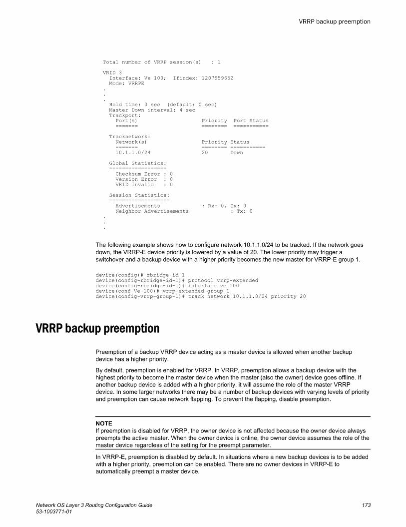
Total number of VRRP session(s) : 1VRID 3 Interface: Ve 100; Ifindex: 1207959652 Mode: VRRPE... Hold time: 0 sec (default: 0 sec) Master Down interval: 4 sec Trackport: Port(s) Priority Port Status ======= ======== =========== Tracknetwork: Network(s) Priority Status ======= ======== =========== 10.1.1.0/24 20 Down Global Statistics: ================== Checksum Error : 0 Version Error : 0 VRID Invalid : 0 Session Statistics: =================== Advertisements : Rx: 0, Tx: 0 Neighbor Advertisements : Tx: 0...
The following example shows how to configure network 10.1.1.0/24 to be tracked. If the network goesdown, the VRRP-E device priority is lowered by a value of 20. The lower priority may trigger aswitchover and a backup device with a higher priority becomes the new master for VRRP-E group 1.
device(config)# rbridge-id 1device(config-rbridge-id-1)# protocol vrrp-extendeddevice(config-rbridge-id-1)# interface ve 100device(conf-Ve-100)# vrrp-extended-group 1device(config-vrrp-group-1)# track network 10.1.1.0/24 priority 20
VRRP backup preemptionPreemption of a backup VRRP device acting as a master device is allowed when another backupdevice has a higher priority.
By default, preemption is enabled for VRRP. In VRRP, preemption allows a backup device with thehighest priority to become the master device when the master (also the owner) device goes offline. Ifanother backup device is added with a higher priority, it will assume the role of the master VRRPdevice. In some larger networks there may be a number of backup devices with varying levels of priorityand preemption can cause network flapping. To prevent the flapping, disable preemption.
NOTEIf preemption is disabled for VRRP, the owner device is not affected because the owner device alwayspreempts the active master. When the owner device is online, the owner device assumes the role of themaster device regardless of the setting for the preempt parameter.
In VRRP-E, preemption is disabled by default. In situations where a new backup devices is to be addedwith a higher priority, preemption can be enabled. There are no owner devices in VRRP-E toautomatically preempt a master device.
VRRP backup preemption
Network OS Layer 3 Routing Configuration Guide 17353-1003771-01
Enabling VRRP backup preemptionAllowing a backup VRRP device that is acting as the master to be preempted by another backupdevice with a higher priority value.
A VRRP or VRRP-E session must be enabled.
Preemption is enabled by default for VRRP, and disabled by default on VRRP-E. Assuming thatpreemption is disabled in a VRRP session, perform the following steps on a VRRP backup device.
1. On the device designated as a backup VRRP device, from privileged EXEC mode, enterconfiguration mode by issuing the configure command.
device# configure2. Enter the rbridge-id command, using the RBridge ID (which has an asterisk next to it when you run
a do show vcs command).
device(config)# rbridge-id 1023. Globally enable the VRRP protocols.
device(config-rbridge-id-102)# protocol vrrp4. Configure the tengigabitethernet interface for the device.
device(config-rbridge-id-102)# interface tengigabitethernet 102/1/5 5. Configure the IP address of the interface:
device(conf-if-te-102/1/5)# ip address 192.168.4.3/24
NOTEThis router is a backup router.
6. Assign the device to VRRP group 1.
device(conf-if-te-102/1/5)# vrrp-group 17. Enter the preempt-mode command to configure backup preemption.
device(conf-vrrp-group-1)# preempt-modeIf a backup device has a higher priority than the current master device, the backup device willassume the role of the VRRP master device after preemption is enabled.
The following example enables preemption on a backup VRRP device.
device# configuredevice(config)# rbridge-id 101device(config-rbridge-id-101)# protocol vrrpdevice(config-rbridge-id-101)# interface tengigabitethernet 102/1/5device(conf-if-te-101/1/5)# ip address 192.168.4.3/24device(conf-if-te-101/1/5)# vrrp-group 1device(config-vrrp-group-1)# preempt-mode
VRRP-E load-balancing using short-path forwardingThe VRRP-E extension for Server Virtualization feature allows Brocade devices to bypass the VRRP-E master router and directly forward packets to their destination through interfaces on the VRRP-Ebackup router. This is called short-path forwarding. A backup router participates in a VRRP-E sessiononly when short-path forwarding is enabled.
Enabling VRRP backup preemption
174 Network OS Layer 3 Routing Configuration Guide53-1003771-01
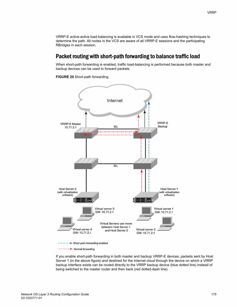
VRRP-E active-active load-balancing is available in VCS mode and uses flow-hashing techniques todetermine the path. All nodes in the VCS are aware of all VRRP-E sessions and the participatingRBridges in each session.
Packet routing with short-path forwarding to balance traffic loadWhen short-path forwarding is enabled, traffic load-balancing is performed because both master andbackup devices can be used to forward packets.
FIGURE 20 Short-path forwarding
If you enable short-path forwarding in both master and backup VRRP-E devices, packets sent by HostServer 1 (in the above figure) and destined for the Internet cloud through the device on which a VRRPbackup interface exists can be routed directly to the VRRP backup device (blue dotted line) instead ofbeing switched to the master router and then back (red dotted-dash line).
VRRP
Network OS Layer 3 Routing Configuration Guide 17553-1003771-01
In the above figure, load-balancing is achieved using short-path forwarding by dynamically moving thevirtual servers between Host Server 1 and Host Server 2.
Short-path forwarding with revert priorityRevert priority is used to dynamically enable or disable VRRP-E short-path forwarding.
If short-path forwarding is configured with revert priority on a backup router, the revert priorityrepresents a threshold for the current priority of the VRRP-E session. When the backup device priorityis higher than the configured revert priority, the backup router is able to perform short-path forwarding.If the backup priority is lower than the revert priority, short-path forwarding is disabled.
Revert priority is supported on both version 2 and version 3 of VRRP-E.
Configuring VRRP-E load-balancing in VCS modeVRRP-E traffic can be load-balanced using short-path forwarding on the backup devices. Short-pathforwarding is only supported in VCS mode.
Before configuring VRRP-E load-balancing, VRRP-E must be configured on all devices in the VRRP-Esession.
Perform this task on all backup VRRP-E Layer 3 devices to allow load sharing within a VRRPextended group.
1. Use the configure command to enter global configuration mode.
device# configure2. Enter the rbridge-id command with an associated RBridge ID to enter RBridge configuration mode
for a specific ID.
device(config)# rbridge-id 1223. To globally enable VRRP-E, enter the protocol vrrp-extended command.
device(config-rbridge-id-122)# protocol vrrp-extended4. Enter the interface ve command with an associated VLAN number.
device(config-rbridge-id-122)# interface ve 2019In this example, virtual Ethernet (ve) configuration mode is entered and the interface is assignedwith a VLAN number of 2019.
5. Enter an IP address for the interface using the ip address command.
device(config-ve-2019)# ip address 192.168.4.1/246. Enter the vrrp-extended-group command with a number to assign a VRRP-E group to the device.
device(config-ve-2018)# vrrp-extended-group 19In this example, VRRP-E group configuration mode is entered.
7. Enter the short-path-forwarding command with a revert-priority value to configure the backupVRRP-E as an alternate path with a specified priority.
device(config-vrrp-extended-group-19)# short-path-forwarding revert-priority 50When the backup device priority is higher than the configured revert-priority value, the backuprouter is able to perform short-path forwarding. If the backup priority is lower than the revert priority,short-path forwarding is disabled.
Short-path forwarding with revert priority
176 Network OS Layer 3 Routing Configuration Guide53-1003771-01
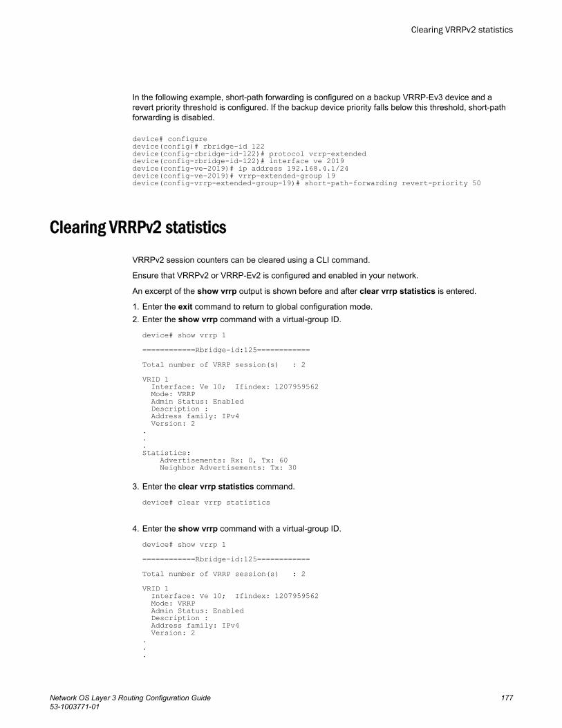
In the following example, short-path forwarding is configured on a backup VRRP-Ev3 device and arevert priority threshold is configured. If the backup device priority falls below this threshold, short-pathforwarding is disabled.
device# configuredevice(config)# rbridge-id 122device(config-rbridge-id-122)# protocol vrrp-extendeddevice(config-rbridge-id-122)# interface ve 2019device(config-ve-2019)# ip address 192.168.4.1/24device(config-ve-2019)# vrrp-extended-group 19device(config-vrrp-extended-group-19)# short-path-forwarding revert-priority 50
Clearing VRRPv2 statisticsVRRPv2 session counters can be cleared using a CLI command.
Ensure that VRRPv2 or VRRP-Ev2 is configured and enabled in your network.
An excerpt of the show vrrp output is shown before and after clear vrrp statistics is entered.
1. Enter the exit command to return to global configuration mode.2. Enter the show vrrp command with a virtual-group ID.
device# show vrrp 1============Rbridge-id:125============Total number of VRRP session(s) : 2VRID 1 Interface: Ve 10; Ifindex: 1207959562 Mode: VRRP Admin Status: Enabled Description : Address family: IPv4 Version: 2...Statistics: Advertisements: Rx: 0, Tx: 60 Neighbor Advertisements: Tx: 30
3. Enter the clear vrrp statistics command.
device# clear vrrp statistics
4. Enter the show vrrp command with a virtual-group ID.
device# show vrrp 1============Rbridge-id:125============Total number of VRRP session(s) : 2VRID 1 Interface: Ve 10; Ifindex: 1207959562 Mode: VRRP Admin Status: Enabled Description : Address family: IPv4 Version: 2...
Clearing VRRPv2 statistics
Network OS Layer 3 Routing Configuration Guide 17753-1003771-01
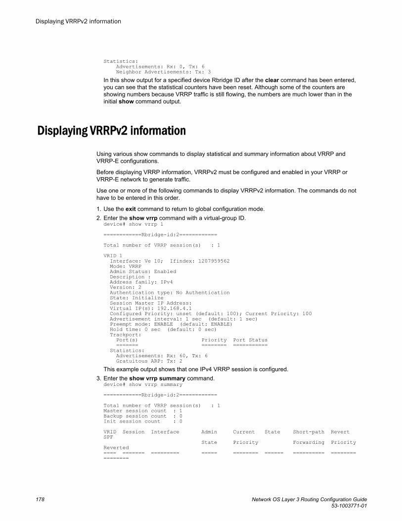
Statistics: Advertisements: Rx: 0, Tx: 6 Neighbor Advertisements: Tx: 3In this show output for a specified device Rbridge ID after the clear command has been entered,you can see that the statistical counters have been reset. Although some of the counters areshowing numbers because VRRP traffic is still flowing, the numbers are much lower than in theinitial show command output.
Displaying VRRPv2 informationUsing various show commands to display statistical and summary information about VRRP andVRRP-E configurations.
Before displaying VRRP information, VRRPv2 must be configured and enabled in your VRRP orVRRP-E network to generate traffic.
Use one or more of the following commands to display VRRPv2 information. The commands do nothave to be entered in this order.
1. Use the exit command to return to global configuration mode.2. Enter the show vrrp command with a virtual-group ID.
device# show vrrp 1============Rbridge-id:2============Total number of VRRP session(s) : 1VRID 1 Interface: Ve 10; Ifindex: 1207959562 Mode: VRRP Admin Status: Enabled Description : Address family: IPv4 Version: 2 Authentication type: No Authentication State: Initialize Session Master IP Address: Virtual IP(s): 192.168.4.1 Configured Priority: unset (default: 100); Current Priority: 100 Advertisement interval: 1 sec (default: 1 sec) Preempt mode: ENABLE (default: ENABLE) Hold time: 0 sec (default: 0 sec) Trackport: Port(s) Priority Port Status ======= ======== =========== Statistics: Advertisements: Rx: 60, Tx: 6 Gratuitous ARP: Tx: 2This example output shows that one IPv4 VRRP session is configured.
3. Enter the show vrrp summary command.device# show vrrp summary============Rbridge-id:2============Total number of VRRP session(s) : 1Master session count : 1Backup session count : 0Init session count : 0VRID Session Interface Admin Current State Short-path Revert SPF State Priority Forwarding Priority Reverted==== ======= ========= ===== ======== ====== ========== ======== ========
Displaying VRRPv2 information
178 Network OS Layer 3 Routing Configuration Guide53-1003771-01
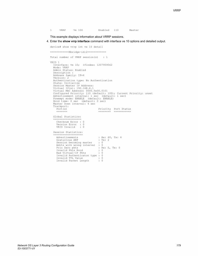
1 VRRP Ve 100 Enabled 110 Master This example displays information about VRRP sessions.
4. Enter the show vrrp interface command with interface ve 10 options and detailed output.
device# show vrrp int ve 10 detail============Rbridge-id:2============Total number of VRRP session(s) : 1VRID 1 Interface: Ve 10; Ifindex: 1207959562 Mode: VRRP Admin Status: Enabled Description : Address family: IPv4 Version: 2 Authentication type: No Authentication State: Initialize Session Master IP Address: Virtual IP(s): 192.168.4.1 Virtual MAC Address: 0000.5e00.0101 Configured Priority: 110 (default: 100); Current Priority: unset Advertisement interval: 1 sec (default: 1 sec) Preempt mode: ENABLE (default: ENABLE) Hold time: 0 sec (default: 0 sec) Master Down interval: 4 sec Trackport: Port(s) Priority Port Status ======= ======== =========== Global Statistics: ================== Checksum Error : 0 Version Error : 0 VRID Invalid : 0 Session Statistics: =================== Advertisements : Rx: 60, Tx: 6 Gratuitous ARP : Tx: 2 Session becoming master : 0 Advts with wrong interval : 0 Prio Zero pkts : Rx: 0, Tx: 0 Invalid Pkts Rvcd : 0 Bad Virtual-IP Pkts : 0 Invalid Authenticaton type : 0 Invalid TTL Value : 0 Invalid Packet Length : 0
VRRP
Network OS Layer 3 Routing Configuration Guide 17953-1003771-01

Displaying VRRPv2 information
180 Network OS Layer 3 Routing Configuration Guide53-1003771-01
VRRPv3
● VRRPv3 overview......................................................................................................... 181● Enabling IPv6 VRRPv3................................................................................................. 182● Enabling IPv4 VRRPv3................................................................................................. 183● Enabling IPv6 VRRP-Ev3..............................................................................................184● Track ports and track priority with VRRP and VRRP-E.................................................185● Track routes and track priority with VRRP-E.................................................................187● VRRP hold timer........................................................................................................... 189● VRRP-E load-balancing using short-path forwarding....................................................190● VRRP-Ev3 sub-second failover.....................................................................................193● VRRPv3 router advertisement suppression.................................................................. 194● Alternate VRRPv2 checksum for VRRPv3 IPv4 sessions.............................................195● Displaying VRRPv3 statistics........................................................................................ 196● Clearing VRRPv3 statistics........................................................................................... 198
VRRPv3 overviewVRRP version 3 (VRRPv3) introduces IPv6 address support to both the standard VRRP and the VRRPenhanced (VRRP-E) protocols.
Virtual Router Redundancy Protocol (VRRP) is designed to eliminate the single point of failure inherentin the static default routed environment by providing redundancy to Layer 3 devices within a local areanetwork (LAN). VRRP uses an election protocol to dynamically assign the default gateway for a host toone of a group of VRRP routers on a LAN. Alternate gateway router paths can be allocated withoutchanging the IP address or MAC address by which the host device knows its gateway.
VRRPv3 implements support for IPv6 addresses for networks using IPv6 and also supports IPv4addresses for dual-stack networks configured with VRRP or VRRP-E. VRRPv3 is compliant with RFC5798. The benefit of implementing VRRPv3 is the faster switchover to backup devices than can beachieved using standard IPv6 Neighbor Discovery mechanisms. With VRRPv3, a backup router canbecome a master router in a few seconds with less overhead traffic and no interaction with the hosts.
When VRRPv3 is configured, the master device that owns the virtual IP address and a master devicethat does not own the virtual IP address, can both respond to ICMP echo requests (ping) and acceptTelnet and other management traffic sent to the virtual IP address. In VRRPv2, only a master device onwhich the virtual IP address is the address of an interface on the master device can respond to ping andother management traffic.
The following are other IPv6 VRRPv3 functionality details:
• VRRPv2 functionality is supported by VRRPv3 except for VRRP authentication.• Two VRRP and VRRP-E sessions cannot share the same group ID on the same interface.
Network OS Layer 3 Routing Configuration Guide 18153-1003771-01
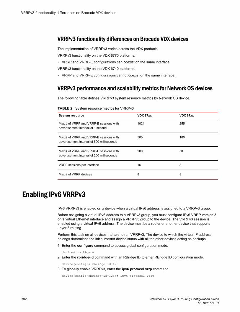
VRRPv3 functionality differences on Brocade VDX devicesThe implementation of VRRPv3 varies across the VDX products.
VRRPv3 functionality on the VDX 8770 platforms.
• VRRP and VRRP-E configurations can coexist on the same interface.
VRRPv3 functionality on the VDX 6740 platforms.
• VRRP and VRRP-E configurations cannot coexist on the same interface.
VRRPv3 performance and scalability metrics for Network OS devicesThe following table defines VRRPv3 system resource metrics by Network OS device.
System resource metrics for VRRPv3TABLE 2
System resource VDX 87xx VDX 67xx
Max # of VRRP and VRRP-E sessions withadvertisement interval of 1 second
1024 255
Max # of VRRP and VRRP-E sessions withadvertisement interval of 500 milliseconds
500 100
Max # of VRRP and VRRP-E sessions withadvertisement interval of 200 milliseconds
200 50
VRRP sessions per interface 16 8
Max # of VRRP devices 8 8
Enabling IPv6 VRRPv3IPv6 VRRPv3 is enabled on a device when a virtual IPv6 address is assigned to a VRRPv3 group.
Before assigning a virtual IPv6 address to a VRRPv3 group, you must configure IPv6 VRRP version 3on a virtual Ethernet interface and assign a VRRPv3 group to the device. The VRRPv3 session isenabled using a virtual IPv6 address. The device must be a router or another device that supportsLayer 3 routing.
Perform this task on all devices that are to run VRRPv3. The device to which the virtual IP addressbelongs determines the initial master device status with all the other devices acting as backups.
1. Enter the configure command to access global configuration mode.
device# configure2. Enter the rbridge-id command with an RBridge ID to enter RBridge ID configuration mode.
device(config)# rbridge-id 1253. To globally enable VRRPv3, enter the ipv6 protocol vrrp command.
device(config-rbridge-id-125)# ipv6 protocol vrrp
VRRPv3 functionality differences on Brocade VDX devices
182 Network OS Layer 3 Routing Configuration Guide53-1003771-01
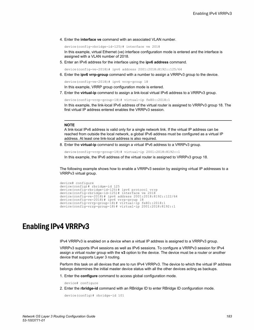
4. Enter the interface ve command with an associated VLAN number.
device(config-rbridge-id-125)# interface ve 2018In this example, virtual Ethernet (ve) interface configuration mode is entered and the interface isassigned with a VLAN number of 2018.
5. Enter an IPv6 address for the interface using the ipv6 address command.
device(config-ve-2018)# ipv6 address 2001:2018:8192::125/646. Enter the ipv6 vrrp-group command with a number to assign a VRRPv3 group to the device.
device(config-ve-2018)# ipv6 vrrp-group 18In this example, VRRP group configuration mode is entered.
7. Enter the virtual-ip command to assign a link-local virtual IPv6 address to a VRRPv3 group.
device(config-vrrp-group-18)# virtual-ip fe80::2018:1In this example, the link-local IPv6 address of the virtual router is assigned to VRRPv3 group 18. Thefirst virtual IP address entered enables the VRRPv3 session.
NOTEA link-local IPv6 address is valid only for a single network link. If the virtual IP address can bereached from outside the local network, a global IPv6 address must be configured as a virtual IPaddress. At least one link-local address is also required.
8. Enter the virtual-ip command to assign a virtual IPv6 address to a VRRPv3 group.
device(config-vrrp-group-18)# virtual-ip 2001:2018:8192::1In this example, the IPv6 address of the virtual router is assigned to VRRPv3 group 18.
The following example shows how to enable a VRRPv3 session by assigning virtual IP addresses to aVRRPv3 virtual group.
device# configuredevice(config)# rbridge-id 125device(config-rbridge-id-125)# ipv6 protocol vrrpdevice(config-rbridge-id-125)# interface ve 2018device(config-ve-2018)# ipv6 address 2001:2018:8192::122/64device(config-ve-2018)# ipv6 vrrp-group 18device(config-vrrp-group-18)# virtual-ip fe80::2018:1device(config-vrrp-group-18)# virtual-ip 2001:2018:8192::1
Enabling IPv4 VRRPv3IPv4 VRRPv3 is enabled on a device when a virtual IP address is assigned to a VRRPv3 group.
VRRPv3 supports IPv4 sessions as well as IPv6 sessions. To configure a VRRPv3 session for IPv4assign a virtual router group with the v3 option to the device. The device must be a router or anotherdevice that supports Layer 3 routing.
Perform this task on all devices that are to run IPv4 VRRPv3. The device to which the virtual IP addressbelongs determines the initial master device status with all the other devices acting as backups.
1. Enter the configure command to access global configuration mode.
device# configure2. Enter the rbridge-id command with an RBridge ID to enter RBridge ID configuration mode.
device(config)# rbridge-id 101
Enabling IPv4 VRRPv3
Network OS Layer 3 Routing Configuration Guide 18353-1003771-01
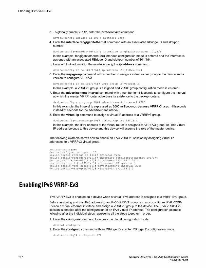
3. To globally enable VRRP, enter the protocol vrrp command.
device(config-rbridge-id-101)# protocol vrrp4. Enter the interface tengigabitethernet command with an associated RBridge ID and slot/port
number.
device(config-rbridge-id-125)# interface tengigabitethernet 101/1/6 In this example, tengigabitethernet (te) interface configuration mode is entered and the interface isassigned with an associated RBridge ID and slot/port number of 101/1/6.
5. Enter an IPv4 address for the interface using the ip address command.
device(config-if-te-101/1/6)# ip address 192.168.5.2/246. Enter the vrrp-group command with a number to assign a virtual router group to the device and a
version to configure VRRPv3.
device(config-if-te-101/1/6)# vrrp-group 10 version 3In this example, a VRRPv3 group is assigned and VRRP group configuration mode is entered.
7. Enter the advertisement-interval command with a number in milliseconds to configure the intervalat which the master VRRP router advertises its existence to the backup routers.
device(config-vrrp-group-10)# advertisement-interval 2000In this example, the interval is expressed as 2000 milliseconds because VRRPv3 uses millisecondsinstead of seconds for the advertisement interval.
8. Enter the virtual-ip command to assign a virtual IP address to a VRRPv3 group.
device(config-vrrp-group-10)# virtual-ip 192.168.5.2In this example, the IPv4 address of the virtual router is assigned to VRRPv3 group 10. This virtualIP address belongs to this device and this device will assume the role of the master device.
The following example shows how to enable an IPv4 VRRPv3 session by assigning virtual IPaddresses to a VRRPv3 virtual group.
device# configuredevice(config)# rbridge-id 101device(config-rbridge-id-101)# protocol vrrpdevice(config-rbridge-id-101)# interface tengigabitethernet 101/1/6 device(config-if-te-101/1/6)# ip address 192.168.5.2/24device(config-if-te-101/1/6)# vrrp-group 10 version 3device(config-vrrp-group-10)# advertisement-interval 2000device(config-vrrp-group-10)# virtual-ip 192.168.5.2
Enabling IPv6 VRRP-Ev3IPv6 VRRP-Ev3 is enabled on a device when a virtual IPv6 address is assigned to a VRRP-Ev3 group.
Before assigning a virtual IPv6 address to an IPv6 VRRPv3 group, you must configure IPv6 VRRP-Ev3 on a virtual ethernet interface and assign a VRRPv3 group to the device. The IPv6 VRRP-Ev3session is enabled after the configuration of an IPv6 virtual IP address. The configuration examplefollowing after the individual steps represents all the steps together in order.
1. Enter the configure command to access the global configuration mode.
device# configure2. Enter the rbridge-id command with an RBridge ID to enter RBridge ID configuration mode.
device(config)# rbridge-id 122
Enabling IPv6 VRRP-Ev3
184 Network OS Layer 3 Routing Configuration Guide53-1003771-01

3. To globally enable VRRP-Ev3, enter the ipv6 protocol vrrp-extended command.
device(config-rbridge-id-122)# ipv6 protocol vrrp-extended4. Enter the interface ve command with an associated VLAN number.
device(config-rbridge-id-122)# interface ve 2019In this example, virtual Ethernet (ve) configuration mode is entered and the interface is assigned witha VLAN number of 2019.
5. Enter an IPv6 address for the interface using the ipv6 address command.
device(config-ve-2019)# ipv6 address 2001:2019:8192::122/646. Enter the ipv6 vrrp-extended-group command with a number to assign a VRRP-E group to the
device.
device(config-ve-2018)# ipv6 vrrp-extended-group 19In this example, VRRP-Ev3 group configuration mode is entered.
7. Enter the virtual-ip command to assign a link-local virtual IPv6 address to a VRRPv3 group.
device(config-vrrp-extended-group-19)# virtual-ip fe80::2019:1In this example, the IPv6 address of the virtual router is assigned to VRRP-Ev3 group 19 and theVRRP-Ev3 session is enabled.
NOTEA maximum of two virtual IPv6 addresses can be configured on VRRP-Ev3 group. For VRRPv3,Brocade recommends using two IPv6 addresses; one link local address and one global address.
8. Enter the virtual-ip command to assign a virtual IPv6 address to a VRRPv3 group.
device(config-vrrp-extended-group-19)# virtual-ip 2001:2019:8192::1In this example, a global IPv6 address is configured for the virtual router.
The following example shows how to enable a VRRP-E-v3 session by assigning a virtual IP address toan extended VRRP-E-v3 virtual group.
device# configuredevice(config)# rbridge-id 122device(config-rbridge-id-122)# ipv6 protocol vrrp-extendeddevice(config-rbridge-id-122)# interface ve 2019device(config-ve-2019)# ipv6 address 2001:2019:8192::122/64device(config-ve-2019)# ipv6 vrrp-extended-group 19device(config-vrrp-extended-group-19)# virtual-ip fe80::2019:1device(config-vrrp-extended-group-19)# virtual-ip 2001:2019:8192::1
After enabling a VRRP-Ev3 session, you may need to configure some optional parameters such asshort-path forwarding for load-balancing or tracking an interface.
Track ports and track priority with VRRP and VRRP-EPort tracking allows interfaces not configured for VRRP or VRRP-E to be monitored for link statechanges that can result in dynamic changes to the VRRP device priority.
A tracked port allows you to monitor the state of the interfaces on the other end of a route path. Atracked interface also allows the virtual router to lower its priority if the exit path interface goes down,allowing another virtual router in the same VRRP (or VRRP-E) group to take over. When a trackedinterface returns to an up state, the configured track priority is added to the current virtual router priorityvalue. The following conditions and limitations exist for tracked ports:
Track ports and track priority with VRRP and VRRP-E
Network OS Layer 3 Routing Configuration Guide 18553-1003771-01
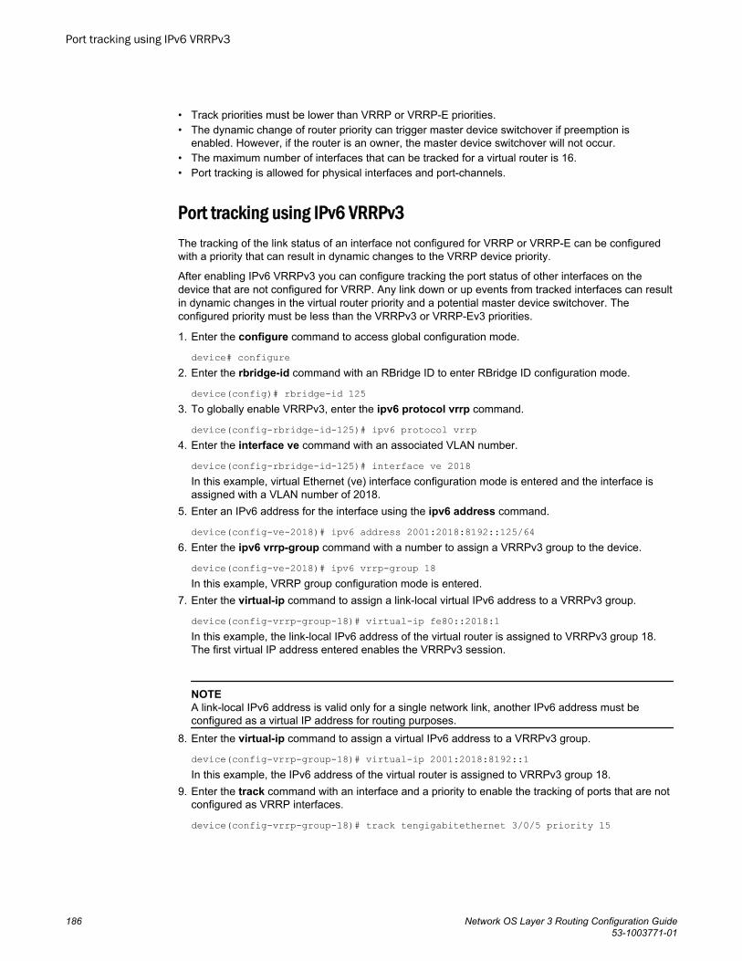
• Track priorities must be lower than VRRP or VRRP-E priorities.• The dynamic change of router priority can trigger master device switchover if preemption is
enabled. However, if the router is an owner, the master device switchover will not occur.• The maximum number of interfaces that can be tracked for a virtual router is 16.• Port tracking is allowed for physical interfaces and port-channels.
Port tracking using IPv6 VRRPv3The tracking of the link status of an interface not configured for VRRP or VRRP-E can be configuredwith a priority that can result in dynamic changes to the VRRP device priority.
After enabling IPv6 VRRPv3 you can configure tracking the port status of other interfaces on thedevice that are not configured for VRRP. Any link down or up events from tracked interfaces can resultin dynamic changes in the virtual router priority and a potential master device switchover. Theconfigured priority must be less than the VRRPv3 or VRRP-Ev3 priorities.
1. Enter the configure command to access global configuration mode.
device# configure2. Enter the rbridge-id command with an RBridge ID to enter RBridge ID configuration mode.
device(config)# rbridge-id 1253. To globally enable VRRPv3, enter the ipv6 protocol vrrp command.
device(config-rbridge-id-125)# ipv6 protocol vrrp4. Enter the interface ve command with an associated VLAN number.
device(config-rbridge-id-125)# interface ve 2018In this example, virtual Ethernet (ve) interface configuration mode is entered and the interface isassigned with a VLAN number of 2018.
5. Enter an IPv6 address for the interface using the ipv6 address command.
device(config-ve-2018)# ipv6 address 2001:2018:8192::125/646. Enter the ipv6 vrrp-group command with a number to assign a VRRPv3 group to the device.
device(config-ve-2018)# ipv6 vrrp-group 18In this example, VRRP group configuration mode is entered.
7. Enter the virtual-ip command to assign a link-local virtual IPv6 address to a VRRPv3 group.
device(config-vrrp-group-18)# virtual-ip fe80::2018:1In this example, the link-local IPv6 address of the virtual router is assigned to VRRPv3 group 18.The first virtual IP address entered enables the VRRPv3 session.
NOTEA link-local IPv6 address is valid only for a single network link, another IPv6 address must beconfigured as a virtual IP address for routing purposes.
8. Enter the virtual-ip command to assign a virtual IPv6 address to a VRRPv3 group.
device(config-vrrp-group-18)# virtual-ip 2001:2018:8192::1In this example, the IPv6 address of the virtual router is assigned to VRRPv3 group 18.
9. Enter the track command with an interface and a priority to enable the tracking of ports that are notconfigured as VRRP interfaces.
device(config-vrrp-group-18)# track tengigabitethernet 3/0/5 priority 15
Port tracking using IPv6 VRRPv3
186 Network OS Layer 3 Routing Configuration Guide53-1003771-01
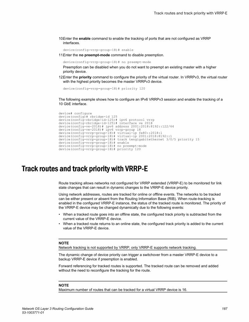
10.Enter the enable command to enable the tracking of ports that are not configured as VRRPinterfaces.
device(config-vrrp-group-18)# enable11.Enter the no preempt-mode command to disable preemption.
device(config-vrrp-group-18)# no preempt-modePreemption can be disabled when you do not want to preempt an existing master with a higherpriority device.
12.Enter the priority command to configure the priority of the virtual router. In VRRPv3, the virtual routerwith the highest priority becomes the master VRRPv3 device.
device(config-vrrp-group-18)# priority 120
The following example shows how to configure an IPv6 VRRPv3 session and enable the tracking of a10 GbE interface.
device# configuredevice(config)# rbridge-id 125device(config-rbridge-id-125)# ipv6 protocol vrrpdevice(config-rbridge-id-125)# interface ve 2018device(config-ve-2018)# ipv6 address 2001:2018:8192::122/64device(config-ve-2018)# ipv6 vrrp-group 18device(config-vrrp-group-18)# virtual-ip fe80::2018:1device(config-vrrp-group-18)# virtual-ip 2001:2018:8192::1device(config-vrrp-group-18)# track tengigabitethernet 3/0/5 priority 15device(config-vrrp-group-18)# enabledevice(config-vrrp-group-18)# no preempt-modedevice(config-vrrp-group-18)# priority 120
Track routes and track priority with VRRP-ERoute tracking allows networks not configured for VRRP extended (VRRP-E) to be monitored for linkstate changes that can result in dynamic changes to the VRRP-E device priority.
Using network addresses, routes are tracked for online or offline events. The networks to be trackedcan be either present or absent from the Routing Information Base (RIB). When route-tracking isenabled in the configured VRRP-E instance, the status of the tracked route is monitored. The priority ofthe VRRP-E device may be changed dynamically due to the following events:
• When a tracked route goes into an offline state, the configured track priority is subtracted from thecurrent value of the VRRP-E device.
• When a tracked route returns to an online state, the configured track priority is added to the currentvalue of the VRRP-E device.
NOTENetwork tracking is not supported by VRRP; only VRRP-E supports network tracking.
The dynamic change of device priority can trigger a switchover from a master VRRP-E device to abackup VRRP-E device if preemption is enabled.
Forward referencing for tracked routes is supported. The tracked route can be removed and addedwithout the need to reconfigure the tracking for the route.
NOTEMaximum number of routes that can be tracked for a virtual VRRP device is 16.
Track routes and track priority with VRRP-E
Network OS Layer 3 Routing Configuration Guide 18753-1003771-01
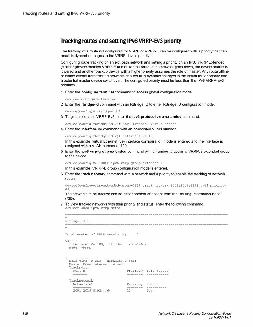
Tracking routes and setting IPv6 VRRP-Ev3 priorityThe tracking of a route not configured for VRRP or VRRP-E can be configured with a priority that canresult in dynamic changes to the VRRP device priority.
Configuring route tracking on an exit path network and setting a priority on an IPv6 VRRP Extended(VRRPE)device enables VRRP-E to monitor the route. If the network goes down, the device priority islowered and another backup device with a higher priority assumes the role of master. Any route offlineor online events from tracked networks can result in dynamic changes in the virtual router priority anda potential master device switchover. The configured priority must be less than the IPv6 VRRP-Ev3priorities.
1. Enter the configure terminal command to access global configuration mode.
device# configure terminal2. Enter the rbridge-id command with an RBridge ID to enter RBridge ID configuration mode.
device(config)# rbridge-id 23. To globally enable VRRP-Ev3, enter the ipv6 protocol vrrp-extended command.
device(config-rbridge-id-2)# ipv6 protocol vrrp-extended4. Enter the interface ve command with an associated VLAN number.
device(config-rbridge-id-2)# interface ve 100In this example, virtual Ethernet (ve) interface configuration mode is entered and the interface isassigned with a VLAN number of 100.
5. Enter the ipv6 vrrp-group-extended command with a number to assign a VRRPv3 extended groupto the device.
device(config-ve-100)# ipv6 vrrp-group-extended 18In this example, VRRP-E group configuration mode is entered.
6. Enter the track network command with a network and a priority to enable the tracking of networkroutes.
device(config-vrrp-extended-group-18)# track network 2001:2019:8192::/64 priority 25The networks to be tracked can be either present or absent from the Routing Information Base(RIB).
7. To view tracked networks with their priority and status, enter the following command:device# show ipv6 vrrp detail ===================================================================================Rbridge-id:1===================================================================================Total number of VRRP session(s) : 1VRID 3 Interface: Ve 100; Ifindex: 1207959652 Mode: VRRPE... Hold time: 0 sec (default: 0 sec) Master Down interval: 4 sec Trackport: Port(s) Priority Port Status ======= ======== =========== Tracknetwork: Network(s) Priority Status ========= ======== ========== 2001:2019:8192::/64 25 Down
Tracking routes and setting IPv6 VRRP-Ev3 priority
188 Network OS Layer 3 Routing Configuration Guide53-1003771-01
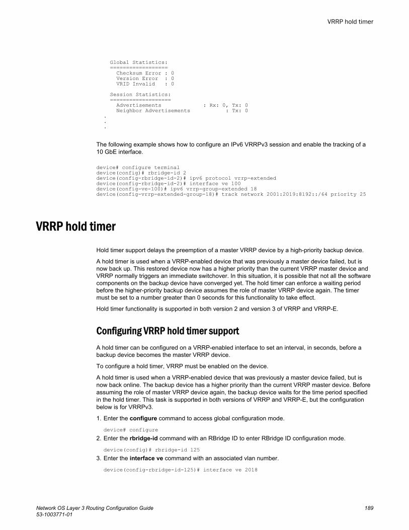
Global Statistics: ================== Checksum Error : 0 Version Error : 0 VRID Invalid : 0 Session Statistics: =================== Advertisements : Rx: 0, Tx: 0 Neighbor Advertisements : Tx: 0...
The following example shows how to configure an IPv6 VRRPv3 session and enable the tracking of a10 GbE interface.
device# configure terminaldevice(config)# rbridge-id 2device(config-rbridge-id-2)# ipv6 protocol vrrp-extendeddevice(config-rbridge-id-2)# interface ve 100device(config-ve-100)# ipv6 vrrp-group-extended 18device(config-vrrp-extended-group-18)# track network 2001:2019:8192::/64 priority 25
VRRP hold timerHold timer support delays the preemption of a master VRRP device by a high-priority backup device.
A hold timer is used when a VRRP-enabled device that was previously a master device failed, but isnow back up. This restored device now has a higher priority than the current VRRP master device andVRRP normally triggers an immediate switchover. In this situation, it is possible that not all the softwarecomponents on the backup device have converged yet. The hold timer can enforce a waiting periodbefore the higher-priority backup device assumes the role of master VRRP device again. The timermust be set to a number greater than 0 seconds for this functionality to take effect.
Hold timer functionality is supported in both version 2 and version 3 of VRRP and VRRP-E.
Configuring VRRP hold timer supportA hold timer can be configured on a VRRP-enabled interface to set an interval, in seconds, before abackup device becomes the master VRRP device.
To configure a hold timer, VRRP must be enabled on the device.
A hold timer is used when a VRRP-enabled device that was previously a master device failed, but isnow back online. The backup device has a higher priority than the current VRRP master device. Beforeassuming the role of master VRRP device again, the backup device waits for the time period specifiedin the hold timer. This task is supported in both versions of VRRP and VRRP-E, but the configurationbelow is for VRRPv3.
1. Enter the configure command to access global configuration mode.
device# configure2. Enter the rbridge-id command with an RBridge ID to enter RBridge ID configuration mode.
device(config)# rbridge-id 1253. Enter the interface ve command with an associated vlan number.
device(config-rbridge-id-125)# interface ve 2018
VRRP hold timer
Network OS Layer 3 Routing Configuration Guide 18953-1003771-01
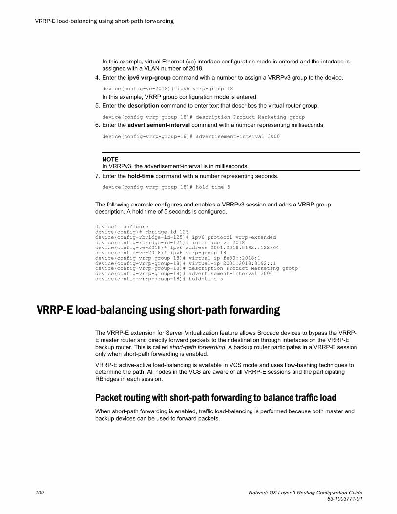
In this example, virtual Ethernet (ve) interface configuration mode is entered and the interface isassigned with a VLAN number of 2018.
4. Enter the ipv6 vrrp-group command with a number to assign a VRRPv3 group to the device.
device(config-ve-2018)# ipv6 vrrp-group 18In this example, VRRP group configuration mode is entered.
5. Enter the description command to enter text that describes the virtual router group.
device(config-vrrp-group-18)# description Product Marketing group6. Enter the advertisement-interval command with a number representing milliseconds.
device(config-vrrp-group-18)# advertisement-interval 3000
NOTEIn VRRPv3, the advertisement-interval is in milliseconds.
7. Enter the hold-time command with a number representing seconds.
device(config-vrrp-group-18)# hold-time 5
The following example configures and enables a VRRPv3 session and adds a VRRP groupdescription. A hold time of 5 seconds is configured.
device# configuredevice(config)# rbridge-id 125device(config-rbridge-id-125)# ipv6 protocol vrrp-extendeddevice(config-rbridge-id-125)# interface ve 2018device(config-ve-2018)# ipv6 address 2001:2018:8192::122/64device(config-ve-2018)# ipv6 vrrp-group 18device(config-vrrp-group-18)# virtual-ip fe80::2018:1device(config-vrrp-group-18)# virtual-ip 2001:2018:8192::1device(config-vrrp-group-18)# description Product Marketing groupdevice(config-vrrp-group-18)# advertisement-interval 3000device(config-vrrp-group-18)# hold-time 5
VRRP-E load-balancing using short-path forwardingThe VRRP-E extension for Server Virtualization feature allows Brocade devices to bypass the VRRP-E master router and directly forward packets to their destination through interfaces on the VRRP-Ebackup router. This is called short-path forwarding. A backup router participates in a VRRP-E sessiononly when short-path forwarding is enabled.
VRRP-E active-active load-balancing is available in VCS mode and uses flow-hashing techniques todetermine the path. All nodes in the VCS are aware of all VRRP-E sessions and the participatingRBridges in each session.
Packet routing with short-path forwarding to balance traffic loadWhen short-path forwarding is enabled, traffic load-balancing is performed because both master andbackup devices can be used to forward packets.
VRRP-E load-balancing using short-path forwarding
190 Network OS Layer 3 Routing Configuration Guide53-1003771-01
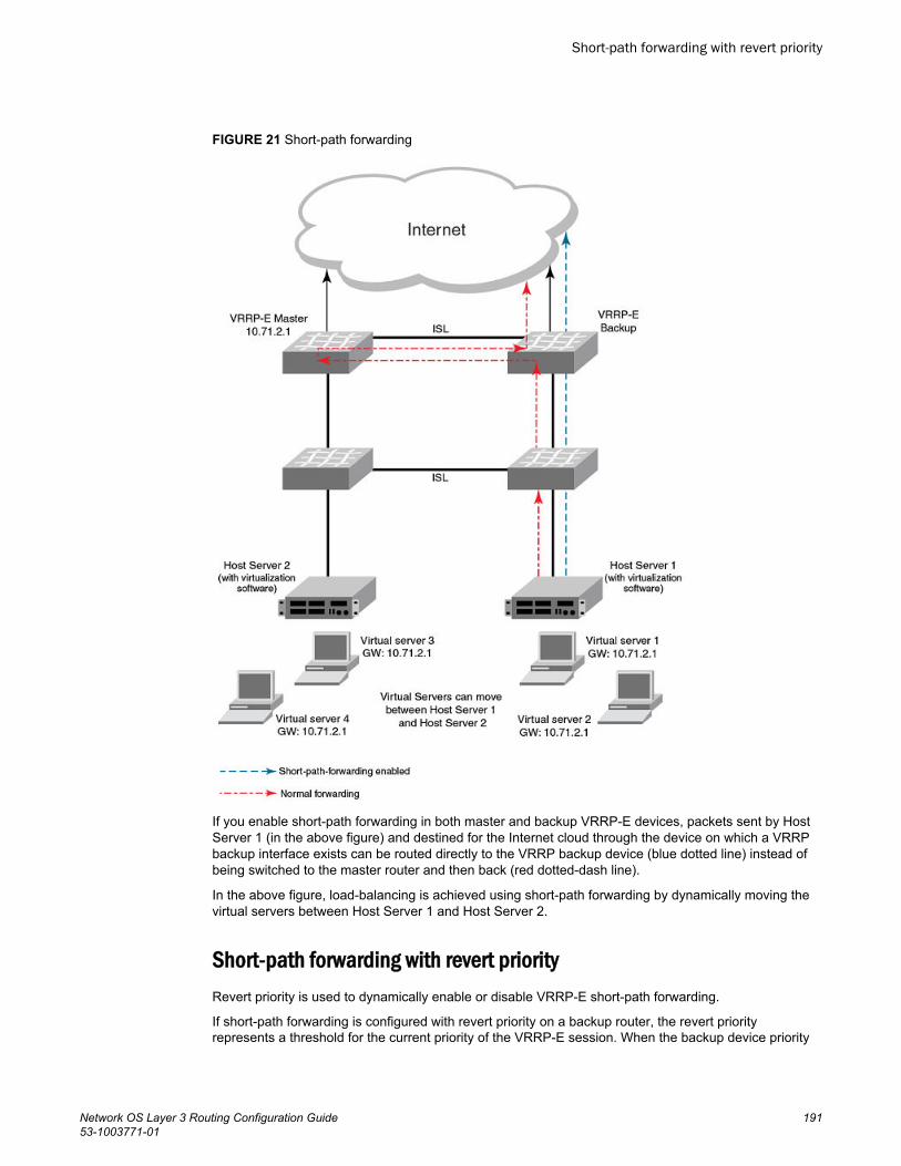
FIGURE 21 Short-path forwarding
If you enable short-path forwarding in both master and backup VRRP-E devices, packets sent by HostServer 1 (in the above figure) and destined for the Internet cloud through the device on which a VRRPbackup interface exists can be routed directly to the VRRP backup device (blue dotted line) instead ofbeing switched to the master router and then back (red dotted-dash line).
In the above figure, load-balancing is achieved using short-path forwarding by dynamically moving thevirtual servers between Host Server 1 and Host Server 2.
Short-path forwarding with revert priorityRevert priority is used to dynamically enable or disable VRRP-E short-path forwarding.
If short-path forwarding is configured with revert priority on a backup router, the revert priorityrepresents a threshold for the current priority of the VRRP-E session. When the backup device priority
Short-path forwarding with revert priority
Network OS Layer 3 Routing Configuration Guide 19153-1003771-01
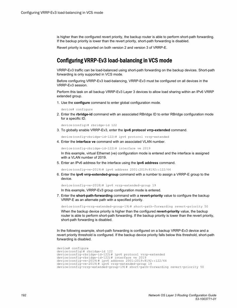
is higher than the configured revert priority, the backup router is able to perform short-path forwarding.If the backup priority is lower than the revert priority, short-path forwarding is disabled.
Revert priority is supported on both version 2 and version 3 of VRRP-E.
Configuring VRRP-Ev3 load-balancing in VCS modeVRRP-Ev3 traffic can be load-balanced using short-path forwarding on the backup devices. Short-pathforwarding is only supported in VCS mode.
Before configuring VRRP-Ev3 load-balancing, VRRP-Ev3 must be configured on all devices in theVRRP-Ev3 session.
Perform this task on all backup VRRP-Ev3 Layer 3 devices to allow load sharing within an IPv6 VRRPextended group.
1. Use the configure command to enter global configuration mode.
device# configure2. Enter the rbridge-id command with an associated RBridge ID to enter RBridge configuration mode
for a specific ID.
device(config)# rbridge-id 1223. To globally enable VRRP-Ev3, enter the ipv6 protocol vrrp-extended command.
device(config-rbridge-id-122)# ipv6 protocol vrrp-extended4. Enter the interface ve command with an associated VLAN number.
device(config-rbridge-id-122)# interface ve 2019In this example, virtual Ethernet (ve) configuration mode is entered and the interface is assignedwith a VLAN number of 2019.
5. Enter an IPv6 address for the interface using the ipv6 address command.
device(config-ve-2019)# ipv6 address 2001:2019:8192::122/646. Enter the ipv6 vrrp-extended-group command with a number to assign a VRRP-E group to the
device.
device(config-ve-2018)# ipv6 vrrp-extended-group 19In this example, VRRP-Ev3 group configuration mode is entered.
7. Enter the short-path-forwarding command with a revert-priority value to configure the backupVRRP-E as an alternate path with a specified priority.
device(config-vrrp-extended-group-19)# short-path-forwarding revert-priority 50When the backup device priority is higher than the configured revert-priority value, the backuprouter is able to perform short-path forwarding. If the backup priority is lower than the revert priority,short-path forwarding is disabled.
In the following example, short-path forwarding is configured on a backup VRRP-Ev3 device and arevert priority threshold is configured. If the backup device priority falls below this threshold, short-pathforwarding is disabled.
device# configuredevice(config)# rbridge-id 122device(config-rbridge-id-122)# ipv6 protocol vrrp-extendeddevice(config-rbridge-id-122)# interface ve 2019device(config-ve-2019)# ipv6 address 2001:2019:8192::122/64device(config-ve-2019)# ipv6 vrrp-extended-group 19device(config-vrrp-extended-group-19)# short-path-forwarding revert-priority 50
Configuring VRRP-Ev3 load-balancing in VCS mode
192 Network OS Layer 3 Routing Configuration Guide53-1003771-01
VRRP-Ev3 sub-second failoverVRRP-Ev3 introduces a scale time factor to the advertisement interval that results in sub-secondfailover times.
In VRRP version 2, an advertisement interval can be set to decrease the time period betweenadvertisements to allow for shorter or longer convergence times. In VRRPv3, a new CLI command isintroduced to allow scaling of the advertisement interval timer. When a scaling value is configured, theexisting advertisement interval timer value is divided by the scaling value. For example, if theadvertisement interval is set to 1 second and the scaling value is set to 10, the new advertisementinterval is 100 milliseconds. Using the timer scaling, VRRP-Ev3 sub-second convergence is possible if amaster fails.
For each VRRP-Ev3 session, the same advertisement interval and scale value should be used. Thereare some limits on the number of VRRP sessions configured with advertisement intervals of one secondor less, for details see the VRRPv3 Performance and Scalability Metrics section.
NOTEBrocade MLX devices only support a scaling factor of 10. For interoperability with MLX devices, use anadvertisement interval scale factor of 10.
Configuring sub-second failover using VRRP-Ev3Configuring a scale factor making the interval between VRRP advertisements to be set in millisecondsallows a sub-second convergence time if a master VRRP device fails.
The configuring sub-second failover using VRRP-Ev3 task is only supported by VRRP-Ev3.
NOTEIncreased timing sensitivity as a result of this configuration could cause protocol flapping during periodsof network congestion.
1. Enter the configure command to access global configuration mode.
device# configure2. Enter the rbridge-id command with an RBridge ID to enter RBridge ID configuration mode.
device(config)# rbridge-id 1223. To globally enable VRRP-Ev3, enter the ipv6 protocol vrrp-extended command.
device(config-rbridge-id-122)# ipv6 protocol vrrp-extended4. Enter the interface ve command with an associated VLAN number.
device(config-rbridge-id-122)# interface ve 2019In this example, virtual Ethernet (ve) configuration mode is entered and the interface is assigned witha VLAN number of 2019.
5. Enter an IPv6 address for the interface using the ipv6 address command.
device(config-ve-2019)# ipv6 address 2001:2019:8192::122/646. Enter the ipv6 vrrp-extended-group command with a number to assign a VRRP-E group to the
device.
device(config-ve-2018)# ipv6 vrrp-extended-group 19In this example, VRRP-Ev3 group configuration mode is entered.
VRRP-Ev3 sub-second failover
Network OS Layer 3 Routing Configuration Guide 19353-1003771-01
7. Enter the advertisement-interval command with a value to set the time period in seconds betweenVRRP advertisements.
device(config-vrrp-extended-group-19)# advertisement-interval 18. Enter the advertisement-interval-scale command with a value of 1, 2, 5, or 10. The VRRP
advertisement interval is divided by this number to set the time period in milliseconds betweenVRRP advertisements.
device(config-vrrp-extended-group-19)# advertisement-interval-scale 10In this example, the scale number of 10 divided into the advertisement interval of 1 sets the intervalbetween advertisements to 100 milliseconds. If a master VRRP-E device fails, the convergencetime to a backup VRRP-E device may be in less than half a second.
The following example demonstrates how to configure a VRRP advertisement interval of 100milliseconds for an IPv6 VRRP-Ev3 group.
device# configuredevice(config)# rbridge-id 122device(config-rbridge-id-122)# ipv6 protocol vrrp-extendeddevice(config-rbridge-id-122)# interface ve 2019device(config-ve-2019)# ipv6 address 2001:2019:8192::122/64device(config-ve-2019)# ipv6 vrrp-extended-group 19device(config-vrrp-extended-group-19)# advertisement-interval 1device(config-vrrp-extended-group-19)# advertisement-interval-scale 10
VRRPv3 router advertisement suppressionVRRPv3 introduces the ability to suppress router advertisements (RAs).
Router advertisements are sent by the VRRP master device and contain the link-local virtual IPaddress and the virtual MAC address. For network security reasons, if you do not want the MACaddresses of interfaces to be viewed, you can disable RA messages. Disabling RA does not removethe auto-configured addresses being sent by VRRP updates, but the RA messages are dropped bythe router interface. There are two other situations where you may want to disable RA messages:
• If an interface is currently the VRRP master but the virtual IP address is not the address of thisinterface, the device should not send RA messages for the interface IP address.
• If the interface is in a backup state, the device should not send RA messages for the interface IPaddress.
Disabling VRRPv3 router advertisementsThe ability to suppress VRRPv3 master device interface router advertisements is introduced.
Suppressing interface router advertisements from the master VRRPv3 device may be performed fornetwork security concerns because the RA messages include the MAC addresses of interfaces. In thistask, VRRP-Ev3 is configured globally and RA messages are suppressed for the virtual ethernet (VE)2109 interface.
NOTETo configure this task for VRRPv3, use the ipv6 protocol vrrp command.
VRRPv3 router advertisement suppression
194 Network OS Layer 3 Routing Configuration Guide53-1003771-01
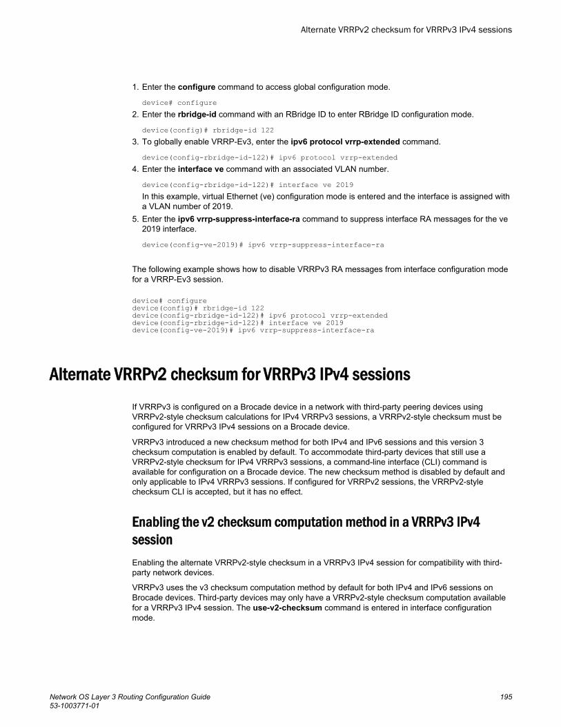
1. Enter the configure command to access global configuration mode.
device# configure2. Enter the rbridge-id command with an RBridge ID to enter RBridge ID configuration mode.
device(config)# rbridge-id 1223. To globally enable VRRP-Ev3, enter the ipv6 protocol vrrp-extended command.
device(config-rbridge-id-122)# ipv6 protocol vrrp-extended4. Enter the interface ve command with an associated VLAN number.
device(config-rbridge-id-122)# interface ve 2019In this example, virtual Ethernet (ve) configuration mode is entered and the interface is assigned witha VLAN number of 2019.
5. Enter the ipv6 vrrp-suppress-interface-ra command to suppress interface RA messages for the ve2019 interface.
device(config-ve-2019)# ipv6 vrrp-suppress-interface-ra
The following example shows how to disable VRRPv3 RA messages from interface configuration modefor a VRRP-Ev3 session.
device# configuredevice(config)# rbridge-id 122device(config-rbridge-id-122)# ipv6 protocol vrrp-extendeddevice(config-rbridge-id-122)# interface ve 2019device(config-ve-2019)# ipv6 vrrp-suppress-interface-ra
Alternate VRRPv2 checksum for VRRPv3 IPv4 sessionsIf VRRPv3 is configured on a Brocade device in a network with third-party peering devices usingVRRPv2-style checksum calculations for IPv4 VRRPv3 sessions, a VRRPv2-style checksum must beconfigured for VRRPv3 IPv4 sessions on a Brocade device.
VRRPv3 introduced a new checksum method for both IPv4 and IPv6 sessions and this version 3checksum computation is enabled by default. To accommodate third-party devices that still use aVRRPv2-style checksum for IPv4 VRRPv3 sessions, a command-line interface (CLI) command isavailable for configuration on a Brocade device. The new checksum method is disabled by default andonly applicable to IPv4 VRRPv3 sessions. If configured for VRRPv2 sessions, the VRRPv2-stylechecksum CLI is accepted, but it has no effect.
Enabling the v2 checksum computation method in a VRRPv3 IPv4sessionEnabling the alternate VRRPv2-style checksum in a VRRPv3 IPv4 session for compatibility with third-party network devices.
VRRPv3 uses the v3 checksum computation method by default for both IPv4 and IPv6 sessions onBrocade devices. Third-party devices may only have a VRRPv2-style checksum computation availablefor a VRRPv3 IPv4 session. The use-v2-checksum command is entered in interface configurationmode.
Alternate VRRPv2 checksum for VRRPv3 IPv4 sessions
Network OS Layer 3 Routing Configuration Guide 19553-1003771-01
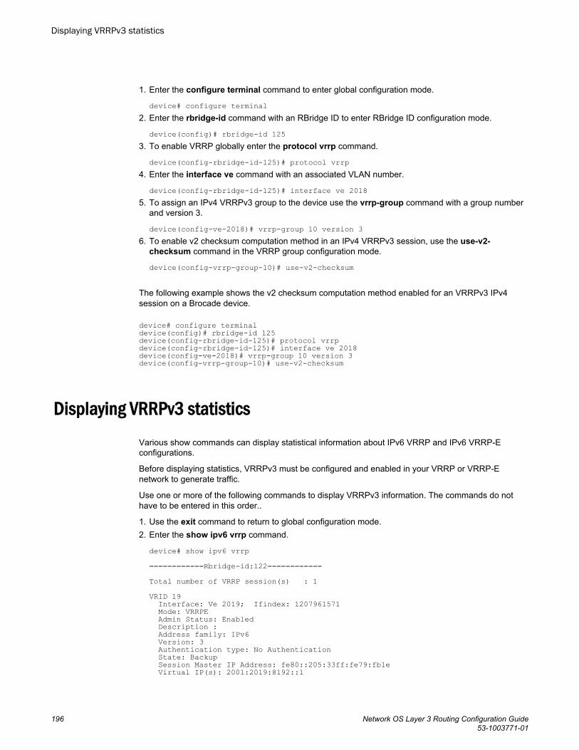
1. Enter the configure terminal command to enter global configuration mode.
device# configure terminal2. Enter the rbridge-id command with an RBridge ID to enter RBridge ID configuration mode.
device(config)# rbridge-id 1253. To enable VRRP globally enter the protocol vrrp command.
device(config-rbridge-id-125)# protocol vrrp4. Enter the interface ve command with an associated VLAN number.
device(config-rbridge-id-125)# interface ve 20185. To assign an IPv4 VRRPv3 group to the device use the vrrp-group command with a group number
and version 3.
device(config-ve-2018)# vrrp-group 10 version 36. To enable v2 checksum computation method in an IPv4 VRRPv3 session, use the use-v2-
checksum command in the VRRP group configuration mode.
device(config-vrrp-group-10)# use-v2-checksum
The following example shows the v2 checksum computation method enabled for an VRRPv3 IPv4session on a Brocade device.
device# configure terminal device(config)# rbridge-id 125device(config-rbridge-id-125)# protocol vrrpdevice(config-rbridge-id-125)# interface ve 2018device(config-ve-2018)# vrrp-group 10 version 3device(config-vrrp-group-10)# use-v2-checksum
Displaying VRRPv3 statisticsVarious show commands can display statistical information about IPv6 VRRP and IPv6 VRRP-Econfigurations.
Before displaying statistics, VRRPv3 must be configured and enabled in your VRRP or VRRP-Enetwork to generate traffic.
Use one or more of the following commands to display VRRPv3 information. The commands do nothave to be entered in this order..
1. Use the exit command to return to global configuration mode.2. Enter the show ipv6 vrrp command.
device# show ipv6 vrrp============Rbridge-id:122============Total number of VRRP session(s) : 1VRID 19 Interface: Ve 2019; Ifindex: 1207961571 Mode: VRRPE Admin Status: Enabled Description : Address family: IPv6 Version: 3 Authentication type: No Authentication State: Backup Session Master IP Address: fe80::205:33ff:fe79:fb1e Virtual IP(s): 2001:2019:8192::1
Displaying VRRPv3 statistics
196 Network OS Layer 3 Routing Configuration Guide53-1003771-01
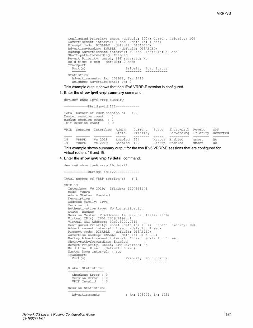
Configured Priority: unset (default: 100); Current Priority: 100 Advertisement interval: 1 sec (default: 1 sec) Preempt mode: DISABLE (default: DISABLED) Advertise-backup: ENABLE (default: DISABLED) Backup Advertisement interval: 60 sec (default: 60 sec) Short-path-forwarding: Enabled Revert Priority: unset; SPF reverted: No Hold time: 0 sec (default: 0 sec) Trackport: Port(s) Priority Port Status ======= ======== =========== Statistics: Advertisements: Rx: 102992, Tx: 1716 Neighbor Advertisements: Tx: 0This example output shows that one IPv6 VRRP-E session is configured.
3. Enter the show ipv6 vrrp summary command.
device# show ipv6 vrrp summary============Rbridge-id:122============Total number of VRRP session(s) : 2Master session count : 1Backup session count : 1Init session count : 0VRID Session Interface Admin Current State Short-path Revert SPF State Priority Forwarding Priority Reverted==== ======= ========= ===== ======== ===== ========== ======== ========18 VRRPE Ve 2018 Enabled 254 Master Enabled unset No 19 VRRPE Ve 2019 Enabled 100 Backup Enabled unset No This example shows summary output for the two IPv6 VRRP-E sessions that are configured forvirtual routers 18 and 19.
4. Enter the show ipv6 vrrp 19 detail command.
device# show ipv6 vrrp 19 detail============Rbridge-id:122============Total number of VRRP session(s) : 1VRID 19 Interface: Ve 2019; Ifindex: 1207961571 Mode: VRRPE Admin Status: Enabled Description : Address family: IPv6 Version: 3 Authentication type: No Authentication State: Backup Session Master IP Address: fe80::205:33ff:fe79:fb1e Virtual IP(s): 2001:2019:8192::1 Virtual MAC Address: 02e0.5200.2513 Configured Priority: unset (default: 100); Current Priority: 100 Advertisement interval: 1 sec (default: 1 sec) Preempt mode: DISABLE (default: DISABLED) Advertise-backup: ENABLE (default: DISABLED) Backup Advertisement interval: 60 sec (default: 60 sec) Short-path-forwarding: Enabled Revert-Priority: unset; SPF Reverted: No Hold time: 0 sec (default: 0 sec) Master Down interval: 4 sec Trackport: Port(s) Priority Port Status ======= ======== =========== Global Statistics: ================== Checksum Error : 0 Version Error : 0 VRID Invalid : 0 Session Statistics: =================== Advertisements : Rx: 103259, Tx: 1721
VRRPv3
Network OS Layer 3 Routing Configuration Guide 19753-1003771-01
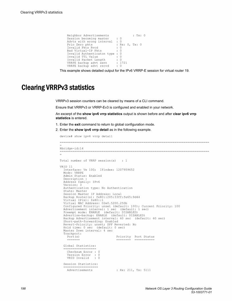
Neighbor Advertisements : Tx: 0 Session becoming master : 0 Advts with wrong interval : 0 Prio Zero pkts : Rx: 0, Tx: 0 Invalid Pkts Rvcd : 0 Bad Virtual-IP Pkts : 0 Invalid Authenticaton type : 0 Invalid TTL Value : 0 Invalid Packet Length : 0 VRRPE backup advt sent : 1721 VRRPE backup advt recvd : 0This example shows detailed output for the IPv6 VRRP-E session for virtual router 19.
Clearing VRRPv3 statisticsVRRPv3 session counters can be cleared by means of a CLI command.
Ensure that VRRPv3 or VRRP-Ev3 is configured and enabled in your network.
An excerpt of the show ipv6 vrrp statistics output is shown before and after clear ipv6 vrrpstatistics is entered.
1. Enter the exit command to return to global configuration mode.2. Enter the show ipv6 vrrp detail as in the following example.
device# show ipv6 vrrp detail ===================================================================================Rbridge-id:14===================================================================================Total number of VRRP session(s) : 1VRID 11 Interface: Ve 100; Ifindex: 1207959652 Mode: VRRPE Admin Status: Enabled Description : Address family: IPv6 Version: 3 Authentication type: No Authentication State: Master Session Master IP Address: Local Backup Router(s): fe80::205:33ff:fe65:9d44 Virtual IP(s): fe80::1 Virtual MAC Address: 02e0.5200.250b Configured Priority: unset (default: 100); Current Priority: 100 Advertisement interval: 1 sec (default: 1 sec) Preempt mode: ENABLE (default: DISABLED) Advertise-backup: ENABLE (default: DISABLED) Backup Advertisement interval: 60 sec (default: 60 sec) Short-path-forwarding: Enabled Revert-Priority: unset; SPF Reverted: No Hold time: 0 sec (default: 0 sec) Master Down interval: 4 sec Trackport: Port(s) Priority Port Status ======= ======== =========== Global Statistics: ================== Checksum Error : 0 Version Error : 0 VRID Invalid : 0 Session Statistics: =================== Advertisements : Rx: 211, Tx: 5111
Clearing VRRPv3 statistics
198 Network OS Layer 3 Routing Configuration Guide53-1003771-01
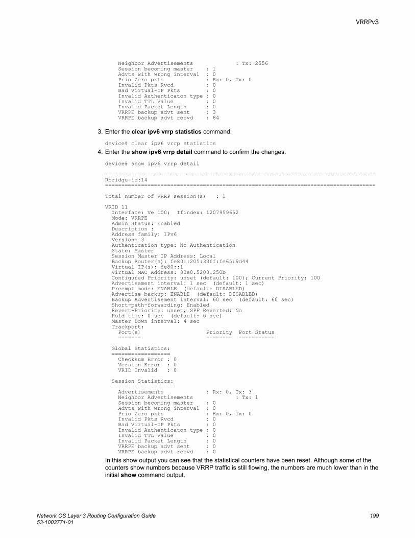
Neighbor Advertisements : Tx: 2556 Session becoming master : 1 Advts with wrong interval : 0 Prio Zero pkts : Rx: 0, Tx: 0 Invalid Pkts Rvcd : 0 Bad Virtual-IP Pkts : 0 Invalid Authenticaton type : 0 Invalid TTL Value : 0 Invalid Packet Length : 0 VRRPE backup advt sent : 3 VRRPE backup advt recvd : 84
3. Enter the clear ipv6 vrrp statistics command.
device# clear ipv6 vrrp statistics4. Enter the show ipv6 vrrp detail command to confirm the changes.
device# show ipv6 vrrp detail ===================================================================================Rbridge-id:14===================================================================================Total number of VRRP session(s) : 1VRID 11 Interface: Ve 100; Ifindex: 1207959652 Mode: VRRPE Admin Status: Enabled Description : Address family: IPv6 Version: 3 Authentication type: No Authentication State: Master Session Master IP Address: Local Backup Router(s): fe80::205:33ff:fe65:9d44 Virtual IP(s): fe80::1 Virtual MAC Address: 02e0.5200.250b Configured Priority: unset (default: 100); Current Priority: 100 Advertisement interval: 1 sec (default: 1 sec) Preempt mode: ENABLE (default: DISABLED) Advertise-backup: ENABLE (default: DISABLED) Backup Advertisement interval: 60 sec (default: 60 sec) Short-path-forwarding: Enabled Revert-Priority: unset; SPF Reverted: No Hold time: 0 sec (default: 0 sec) Master Down interval: 4 sec Trackport: Port(s) Priority Port Status ======= ======== =========== Global Statistics: ================== Checksum Error : 0 Version Error : 0 VRID Invalid : 0 Session Statistics: =================== Advertisements : Rx: 0, Tx: 3 Neighbor Advertisements : Tx: 1 Session becoming master : 0 Advts with wrong interval : 0 Prio Zero pkts : Rx: 0, Tx: 0 Invalid Pkts Rvcd : 0 Bad Virtual-IP Pkts : 0 Invalid Authenticaton type : 0 Invalid TTL Value : 0 Invalid Packet Length : 0 VRRPE backup advt sent : 0 VRRPE backup advt recvd : 0In this show output you can see that the statistical counters have been reset. Although some of thecounters show numbers because VRRP traffic is still flowing, the numbers are much lower than in theinitial show command output.
VRRPv3
Network OS Layer 3 Routing Configuration Guide 19953-1003771-01

Clearing VRRPv3 statistics
200 Network OS Layer 3 Routing Configuration Guide53-1003771-01
BFD
● Bidirectional Forwarding Detection (BFD).....................................................................201● General BFD considerations and limitations................................................................. 202● BFD on Network OS hardware platforms......................................................................202● BFD for Layer 3 protocols............................................................................................. 204● BFD considerations and limitations for Layer 3 protocols............................................. 205● BFD for Layer 3 protocols on virtual Ethernet interfaces.............................................. 206● BFD for Layer 3 protocols on vLAGs............................................................................ 207● Configuring BFD on an interface...................................................................................207● Disabling BFD on an interface...................................................................................... 208● BFD for BGP................................................................................................................. 208● BFD for OSPF............................................................................................................... 213● BFD for VXLAN extension tunnels................................................................................ 218● BFD for NSX tunnels.....................................................................................................221● BFD for static routes..................................................................................................... 222● Displaying BFD information...........................................................................................226
Bidirectional Forwarding Detection (BFD)BFD is a unified detection mechanism used to rapidly detect link faults. BFD improves networkperformance by providing fast forwarding path failure detection times.
BFD provides rapid detection of the failure of a forwarding path by checking that the next-hop device isalive. When BFD is not enabled, it can take from 3 to 30 seconds to detect that a neighboring device isnot operational. This causes packet loss due to incorrect routing information at a level unacceptable forreal-time applications such as VOIP and video over IP.
Using BFD, you can detect a forwarding path failure in 150 milliseconds.
A BFD session is automatically established when a neighbor is discovered for a protocol, provided thatBFD is enabled on the interface on which the neighbor is detected and BFD is also enabled for theprotocol at interface level or globally. Once a session is established, each device transmits controlmessages at a high rate of speed that is negotiated by the devices during the session setup. To providea detection time of 150 milliseconds, it is necessary to process 20 messages per second of about 70 to100 bytes each per session. A similar number of messages also need to be transmitted out per session.Once a session is established, that same message is continuously transmitted at the negotiated rateand a check is made that the expected control message is received at the agreed frequency from theneighbor. If the agreed upon messages are not received from the neighbor within a short period of time,the neighbor is considered to be down.
BFD can provide failure detection on any kind of path between systems, including direct physical links,multihop routed paths, and tunnels. Multiple BFD sessions can be established between the same pair ofsystems when multiple paths between them are present in at least one direction, even if a lessernumber of paths are available in the other direction.
Network OS Layer 3 Routing Configuration Guide 20153-1003771-01
NOTEBFD session establishment on an interface does not start until 5 seconds after the interface comes up.The reason for this delay is to ensure that the link is not affected by unstable link conditions whichcould cause BFD to flap. This delay time is not user configurable.
For singlehop, the BFD Control Message is a UDP message with destination port 3784. For multihop,the BFD Control Message is a UDP message with destination port 4784 sent over IPv4 or IPv6,depending on which data forwarding path failure BFD is trying to detect.
NOTEThe source port for BFD control packets is in the range 49152 through 65535. The source port numberis unique among all BFD sessions on the system.
NOTEFor singlehop sessions, all BFD control packets are sent with a time to live (TTL) or hop limit value of255. All received BFD control packets are discarded if the received TTL or hop limit is not equal to255.
General BFD considerations and limitationsThere are a number of general points to consider when configuring BFD.
• BFD is not supported on Layer 3 port channels.• BFD is supported on Layer 2 port channels used by SVI sessions. Refer to the Network OS Layer 2
Switching Configuration Guide for more information on Layer 2 port channels. For trunk ports, activeBFD sessions are started on the line card (LC) with the primary port. Inactive BFD sessions arestarted on all other LCs with secondary member ports. The BFD state machine is replicated on allLCs. Inactive sessions on other LCs receive control packets that arrive from alternate paths.Session timeouts are triggered if control packets are not received on any path.
• BFD protocol version 1 is supported. BFD version 0 is not supported. BFD version 1 and BFDversion 0 are not compatible.
• BFD singlehop sessions always use the primary IP address as the source address. Secondary IPaddresses cannot be used as source addresses on single hop sessions.
Refer to the BFD considerations and limitations for Layer 3 protocols section of this chapter and theBFD considerations and limitations for static routes section of the “IP Route Policy” chapter for moreinformation on BFD considerations and limitations.
BFD on Network OS hardware platformsA single instance of BFD runs on stackable switch platforms, and BFD sessions cannot be offloaded.On chassis-based platforms support for offloading BFD sessions to line cards is provided, helping toachieve scalability.
The figure below shows BFD running on a stackable switch platform, where BFD sessions are notoffloaded. BFD is responsible for providing the forwarding path failure detection service to a routingprotocol.
General BFD considerations and limitations
202 Network OS Layer 3 Routing Configuration Guide53-1003771-01
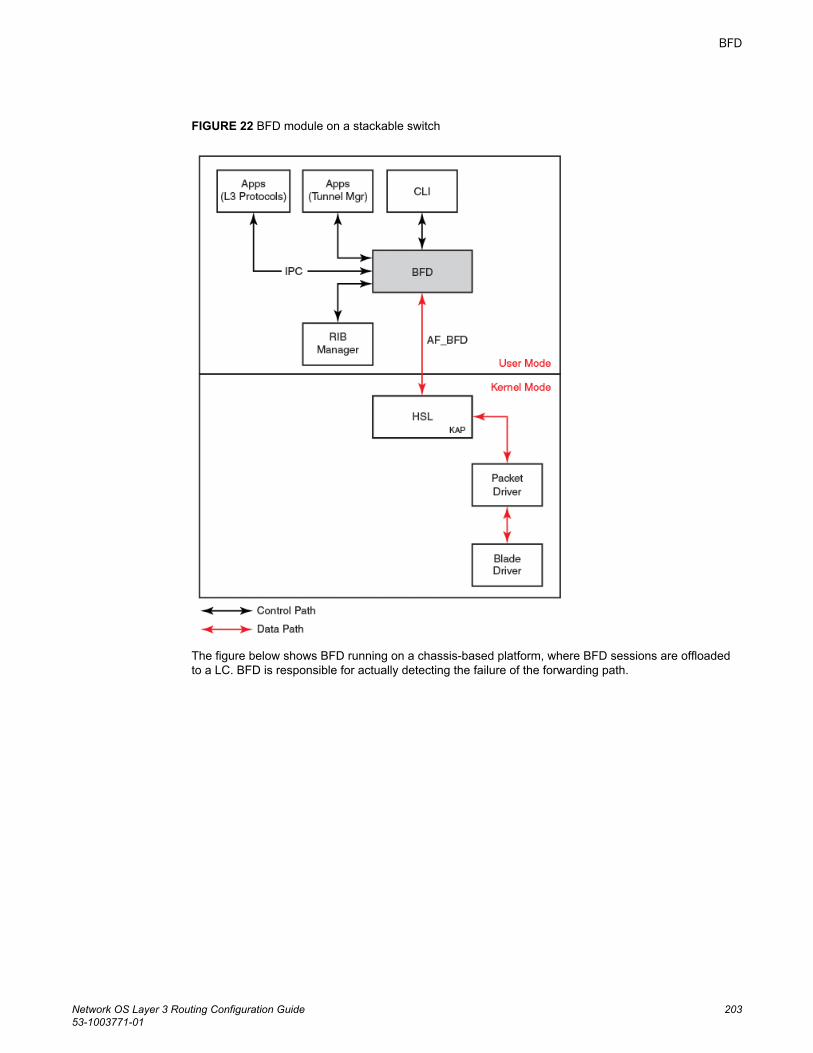
FIGURE 22 BFD module on a stackable switch
The figure below shows BFD running on a chassis-based platform, where BFD sessions are offloadedto a LC. BFD is responsible for actually detecting the failure of the forwarding path.
BFD
Network OS Layer 3 Routing Configuration Guide 20353-1003771-01
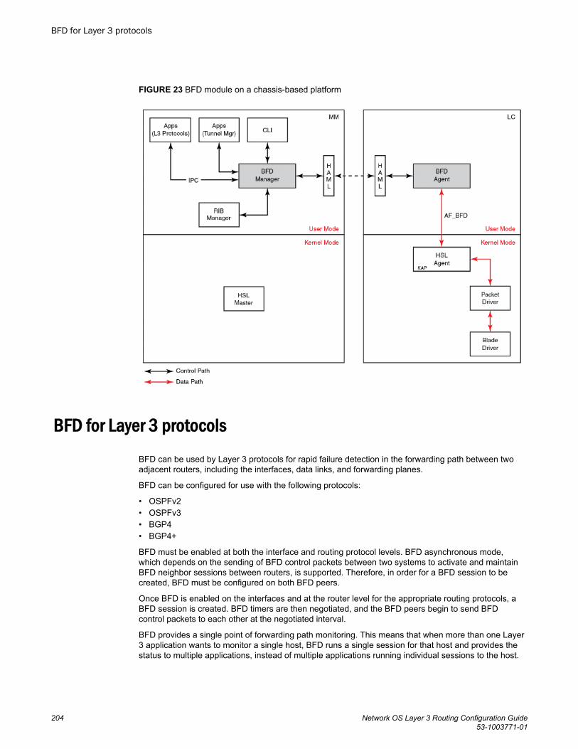
FIGURE 23 BFD module on a chassis-based platform
BFD for Layer 3 protocolsBFD can be used by Layer 3 protocols for rapid failure detection in the forwarding path between twoadjacent routers, including the interfaces, data links, and forwarding planes.
BFD can be configured for use with the following protocols:
• OSPFv2• OSPFv3• BGP4• BGP4+
BFD must be enabled at both the interface and routing protocol levels. BFD asynchronous mode,which depends on the sending of BFD control packets between two systems to activate and maintainBFD neighbor sessions between routers, is supported. Therefore, in order for a BFD session to becreated, BFD must be configured on both BFD peers.
Once BFD is enabled on the interfaces and at the router level for the appropriate routing protocols, aBFD session is created. BFD timers are then negotiated, and the BFD peers begin to send BFDcontrol packets to each other at the negotiated interval.
BFD provides a single point of forwarding path monitoring. This means that when more than one Layer3 application wants to monitor a single host, BFD runs a single session for that host and provides thestatus to multiple applications, instead of multiple applications running individual sessions to the host.
BFD for Layer 3 protocols
204 Network OS Layer 3 Routing Configuration Guide53-1003771-01
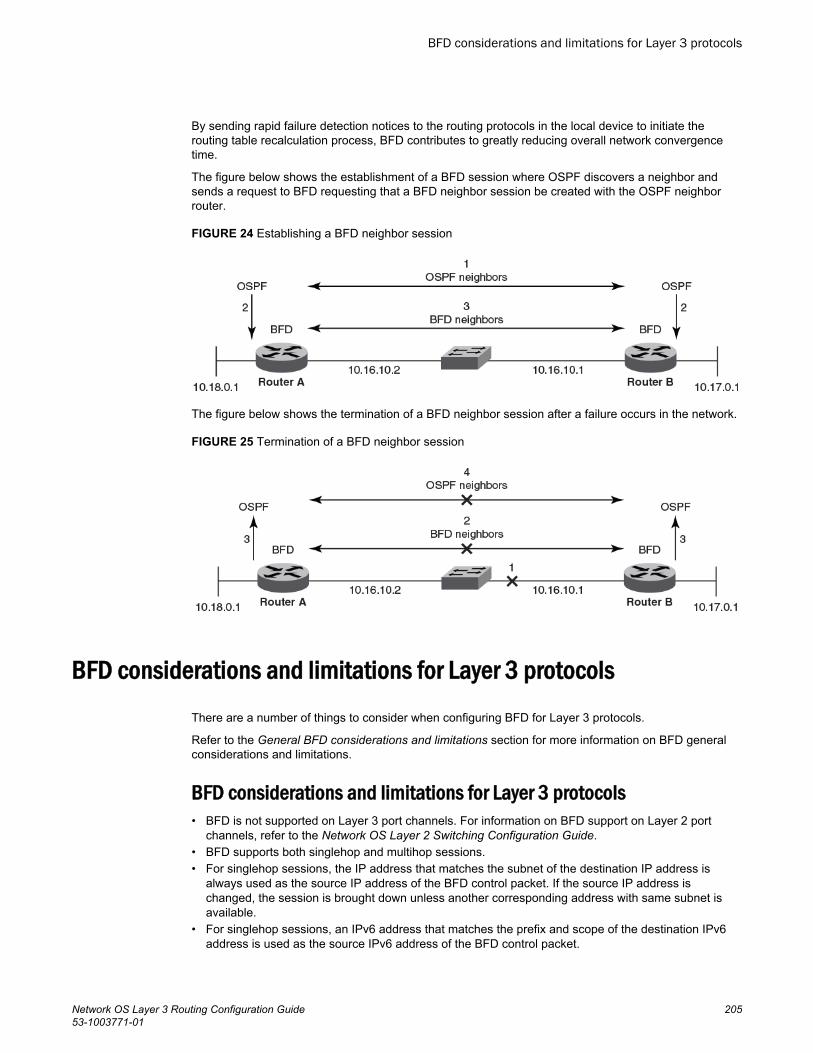
By sending rapid failure detection notices to the routing protocols in the local device to initiate therouting table recalculation process, BFD contributes to greatly reducing overall network convergencetime.
The figure below shows the establishment of a BFD session where OSPF discovers a neighbor andsends a request to BFD requesting that a BFD neighbor session be created with the OSPF neighborrouter.
FIGURE 24 Establishing a BFD neighbor session
The figure below shows the termination of a BFD neighbor session after a failure occurs in the network.
FIGURE 25 Termination of a BFD neighbor session
BFD considerations and limitations for Layer 3 protocolsThere are a number of things to consider when configuring BFD for Layer 3 protocols.
Refer to the General BFD considerations and limitations section for more information on BFD generalconsiderations and limitations.
BFD considerations and limitations for Layer 3 protocols• BFD is not supported on Layer 3 port channels. For information on BFD support on Layer 2 port
channels, refer to the Network OS Layer 2 Switching Configuration Guide.• BFD supports both singlehop and multihop sessions.• For singlehop sessions, the IP address that matches the subnet of the destination IP address is
always used as the source IP address of the BFD control packet. If the source IP address ischanged, the session is brought down unless another corresponding address with same subnet isavailable.
• For singlehop sessions, an IPv6 address that matches the prefix and scope of the destination IPv6address is used as the source IPv6 address of the BFD control packet.
BFD considerations and limitations for Layer 3 protocols
Network OS Layer 3 Routing Configuration Guide 20553-1003771-01
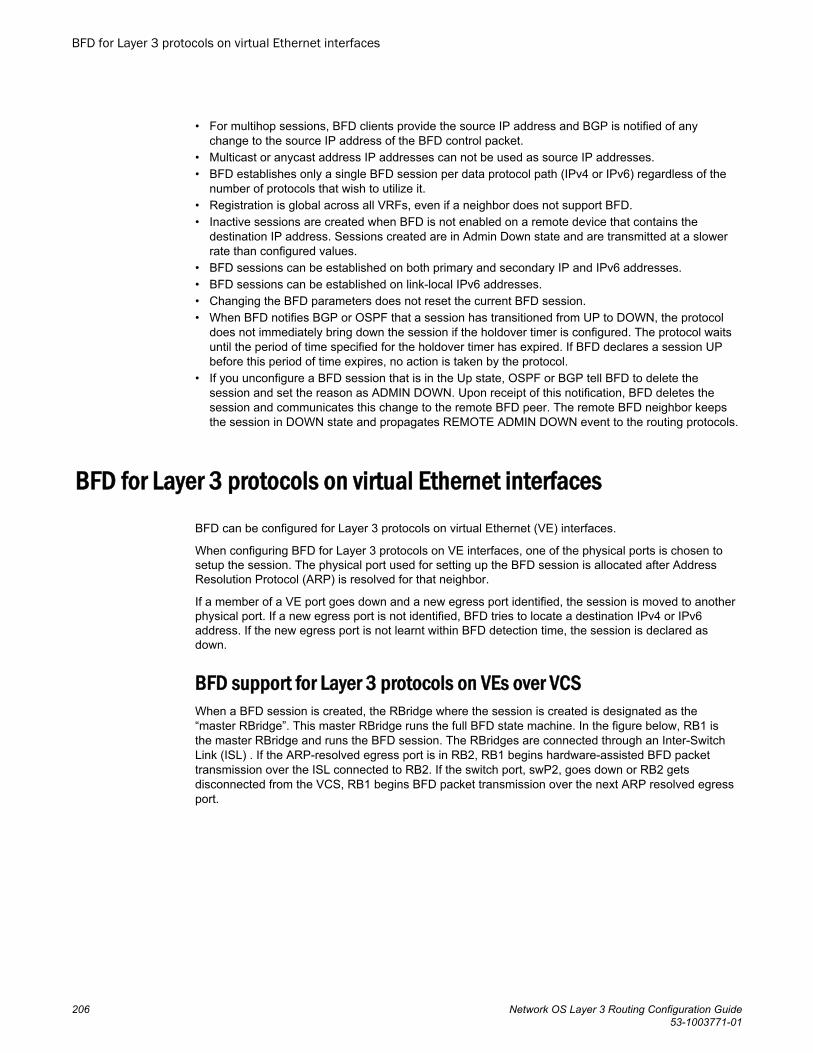
• For multihop sessions, BFD clients provide the source IP address and BGP is notified of anychange to the source IP address of the BFD control packet.
• Multicast or anycast address IP addresses can not be used as source IP addresses.• BFD establishes only a single BFD session per data protocol path (IPv4 or IPv6) regardless of the
number of protocols that wish to utilize it.• Registration is global across all VRFs, even if a neighbor does not support BFD.• Inactive sessions are created when BFD is not enabled on a remote device that contains the
destination IP address. Sessions created are in Admin Down state and are transmitted at a slowerrate than configured values.
• BFD sessions can be established on both primary and secondary IP and IPv6 addresses.• BFD sessions can be established on link-local IPv6 addresses.• Changing the BFD parameters does not reset the current BFD session.• When BFD notifies BGP or OSPF that a session has transitioned from UP to DOWN, the protocol
does not immediately bring down the session if the holdover timer is configured. The protocol waitsuntil the period of time specified for the holdover timer has expired. If BFD declares a session UPbefore this period of time expires, no action is taken by the protocol.
• If you unconfigure a BFD session that is in the Up state, OSPF or BGP tell BFD to delete thesession and set the reason as ADMIN DOWN. Upon receipt of this notification, BFD deletes thesession and communicates this change to the remote BFD peer. The remote BFD neighbor keepsthe session in DOWN state and propagates REMOTE ADMIN DOWN event to the routing protocols.
BFD for Layer 3 protocols on virtual Ethernet interfacesBFD can be configured for Layer 3 protocols on virtual Ethernet (VE) interfaces.
When configuring BFD for Layer 3 protocols on VE interfaces, one of the physical ports is chosen tosetup the session. The physical port used for setting up the BFD session is allocated after AddressResolution Protocol (ARP) is resolved for that neighbor.
If a member of a VE port goes down and a new egress port identified, the session is moved to anotherphysical port. If a new egress port is not identified, BFD tries to locate a destination IPv4 or IPv6address. If the new egress port is not learnt within BFD detection time, the session is declared asdown.
BFD support for Layer 3 protocols on VEs over VCSWhen a BFD session is created, the RBridge where the session is created is designated as the“master RBridge”. This master RBridge runs the full BFD state machine. In the figure below, RB1 isthe master RBridge and runs the BFD session. The RBridges are connected through an Inter-SwitchLink (ISL) . If the ARP-resolved egress port is in RB2, RB1 begins hardware-assisted BFD packettransmission over the ISL connected to RB2. If the switch port, swP2, goes down or RB2 getsdisconnected from the VCS, RB1 begins BFD packet transmission over the next ARP resolved egressport.
BFD for Layer 3 protocols on virtual Ethernet interfaces
206 Network OS Layer 3 Routing Configuration Guide53-1003771-01
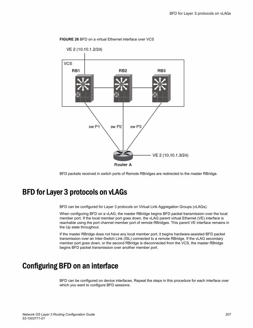
FIGURE 26 BFD on a virtual Ethernet interface over VCS
BFD packets received in switch ports of Remote RBridges are redirected to the master RBridge.
BFD for Layer 3 protocols on vLAGsBFD can be configured for Layer 3 protocols on Virtual Link Aggregation Groups (vLAGs).
When configuring BFD on a vLAG, the master RBridge begins BFD packet transmission over the localmember port. If the local member port goes down, the vLAG parent virtual Ethernet (VE) interface isreachable using the port channel member port of remote RBridges. This parent VE interface remains inthe Up state throughout.
If the master RBridge does not have any local member port, it begins hardware-assisted BFD packettransmission over an Inter-Switch Link (ISL) connected to a remote RBridge. If the vLAG secondarymember port goes down, or the second RBridge is disconnected from the VCS, the master RBridgebegins BFD packet transmission over another member port.
Configuring BFD on an interfaceBFD can be configured on device interfaces. Repeat the steps in this procedure for each interface overwhich you want to configure BFD sessions.
BFD for Layer 3 protocols on vLAGs
Network OS Layer 3 Routing Configuration Guide 20753-1003771-01
1. Enter the configure terminal command to access global configuration mode.
device# configure terminal2. Enter the interface command and specify an interface.
device(config)# interface tengigabitethernet 1/0/13. Enter the bfd interval command with the min-rx and multiplier keywords to configure BFD session
parameters on the interface. For information on the default parameters for the bfd intervalcommand, refer to the Network OS Command Reference.
device(config-if-te-1/0/1)# bfd interval 110 min-rx 120 multiplier 15
This example configures BFD on a specific 10-gigabit Ethernet interface by setting the baseline BFDsession parameters on that interface.
device# configure terminaldevice(config)# interface tengigabitethernet 1/0/1device(config-if-te-1/0/1)# bfd interval 110 min-rx 120 multiplier 15
Disabling BFD on an interfaceBFD can be disabled on device interfaces. Repeat the steps in this procedure for each interface overwhich you want to disable BFD sessions.
1. Enter the configure terminal command to access global configuration mode.
device# configure terminal2. Enter the interface command and specify an interface.
device(config)# interface tengigabitethernet 1/0/13. Enter the bfd shutdown command to disable BFD on the interface.
device(config-if-te-1/0/1)# bfd shutdown
This example disables BFD on a specific 10-gigabit Ethernet interface .
device# configure terminaldevice(config)# interface tengigabitethernet 1/0/1device(config-if-te-1/0/1)# bfd shutdown
BFD for BGPBFD support for BGP4 and BGP4+ can be configured so that BGP is a registered protocol with BFDand receives forwarding path detection failure messages from BFD.
BFD is supported for BGP and is disabled by default. BFD rapidly detect faults on links between BGPpeers and reports faults to BGP. BFD for BGP is supported for both for singlehop and multihop IBGPand EBGP sessions with either IPv4 or IPv6 neighbors in the default VRF and in nondefault VRFinstances. BFD behavior is identical for IBGP and EBGP singlehop and multihop sessions, and forIPv4 and IPv6 neighbors.
Consider the following when configuring BFD for BGP:
Disabling BFD on an interface
208 Network OS Layer 3 Routing Configuration Guide53-1003771-01
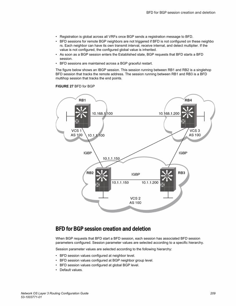
• Registration is global across all VRFs once BGP sends a registration message to BFD.• BFD sessions for remote BGP neighbors are not triggered if BFD is not configured on these neighbo
rs. Each neighbor can have its own transmit interval, receive internal, and detect multiplier. If thevalue is not configured, the configured global value is inherited.
• As soon as a BGP session enters the Established state, BGP requests that BFD starts a BFDsession.
• BFD sessions are maintained across a BGP graceful restart.
The figure below shows an IBGP session. This session running between RB1 and RB2 is a singlehopBFD session that tracks the remote address. The session running between RB1 and RB3 is a BFDmultihop session that tracks the end points.
FIGURE 27 BFD for BGP
BFD for BGP session creation and deletionWhen BGP requests that BFD start a BFD session, each session has associated BFD sessionparameters configured. Session parameter values are selected according to a specific hierarchy.
Session parameter values are selected according to the following hierarchy:
• BFD session values configured at neighbor level.• BFD session values configured at BGP neighbor group level.• BFD session values configured at global BGP level.• Default values.
BFD for BGP session creation and deletion
Network OS Layer 3 Routing Configuration Guide 20953-1003771-01
BFD sessions are deleted for a particular source or destination IPv4 or IPv6 address when a BGPsession moves from the Established state to another BGP state.
BFD sessions are deleted when a BGP session for a neighbor is un-configured locally. If youunconfigure a BGP session that is in an Established state and running a BFD session with a neighborthat is up, BGP sends a CEASE message to the peer and deletes the BFD session. Upon receipt ofthis CEASE message, the neighbor deletes the BFD session and moves to an IDLE state.
Configuring BFD session parameters for BGPBFD session parameters can be set globally for BGP-enabled interfaces.
1. Enter the configure terminal command to access global configuration mode.
device# configure terminal2. Enter the rbridge-id command with an RBridge ID to enter RBridge ID configuration mode.
device(config)# rbridge-id 1223. Enter the router bgp command to enable BGP routing.
device(config-rbridge-id-122)# router bgp4. Enter the bfd interval command with the min-rx and multiplier keywords to configure BFD session
parameters globally for BGP-enabled interfaces.
device(config-bgp-router)# bfd interval 110 min-rx 120 multiplier 15
NOTEThe bfd interval command is used for singlehop sessions only. Multihop sessions in BGP useeither the values configured at interface level using the bfd interval command or the default intervalvalues.
5. Enter the bfd holdover-interval command and specify a value to set the BFD holdover intervalglobally for BGP-enabled interfaces.
device(config-bgp-router)# bfd holdover-interval 15
This example configures BFD session parameters globally for BGP-enabled interfaces.
device# configure terminaldevice(config)# rbridge-id 122device(config-rbridge-id-122)# router bgpdevice(config-bgp-router)# bfd interval 110 min-rx 120 multiplier 15device(config-bgp-router)# bfd holdover-interval 15
Enabling BFD sessions for a specified BGP neighborBFD sessions can be configured for specified BGP neighbors.
1. Enter the configure terminal command to access global configuration mode.
device# configure terminal2. Enter the rbridge-id command with an RBridge ID to enter RBridge ID configuration mode.
device(config)# rbridge-id 1223. Enter the router bgp command to enable BGP routing.
device(config-rbridge-id-122)# router bgp
Configuring BFD session parameters for BGP
210 Network OS Layer 3 Routing Configuration Guide53-1003771-01
4. Enter the neighbor bfd command, specifying an IP address, to enable BFD sessions for thespecified neighbor.
device(config-bgp-router)# neighbor 10.10.1.1 bfd5. Enter the neighbor bfd command, specifying an IP address, with the interval, min-rx, and
multiplier keywords to set the BFD session timer values for the specified BGP neighbor.
device(config-bgp-router)# neighbor 10.10.1.1 bfd interval 120 min-rx 140 multiplier 10
6. Enter the neighbor bfd holdover-interval command, specifying an IP address, and enter a value toset the BFD holdover interval for the specified BGP neighbor.
device(config-bgp-router)# neighbor 10.10.1.1 bfd holdover-interval 12
This example enables a BFD session for a BGP neighbor with the IP address 10.10.1.1 and configuresthe BFD session parameters.
device# configure terminaldevice(config)# rbridge-id 122device(config-rbridge-id-122)# router bgpdevice(config-bgp-router)# neighbor 10.10.1.1 bfddevice(config-bgp-router)# neighbor 10.10.1.1 bfd interval 120 min-rx 140 multiplier 10device(config-bgp-router)# neighbor 10.10.1.1 bfd holdover-interval 12
Enabling BFD sessions for a specified BGP neighbor in a nondefaultVRFBFD sessions can be configured for specified BGP neighbors in a nondefault VRF instance.
1. Enter the configure terminal command to access global configuration mode.
device# configure terminal2. Enter the rbridge-id command with an RBridge ID to enter RBridge ID configuration mode.
device(config)# rbridge-id 1223. Enter the router bgp command to enable BGP routing.
device(config-rbridge-id-122)# router bgp4. Enter the address-family ipv4 unicast command with the vrf keyword, specifying a VRF name, to
enter BGP address-family IPv4 unicast VRF configuration mode.
device(config-bgp-router)# address-family ipv4 unicast vrf green5. Enter the neighbor bfd command, specifying an IP address, to enable BFD sessions for the
specified neighbor in a nondefault VRF instance.
device(config-bgp-ipv4u-vrf)# neighbor 10.10.1.1 bfd6. Enter the neighbor bfd command, specifying an IP address, with the interval, min-rx, and
multiplier keywords to set the BFD session timer values for the specified BGP neighbor in anondefault VRF instance.
device(config-bgp-ipv4u-vrf)# neighbor 10.10.1.1 bfd interval 120 min-rx 140 multiplier 10
7. Enter the bfd holdover-interval command, specifying an IP address, and enter a value to set theBFD holdover interval for the specified BGP neighbor in a nondefault VRF instance.
device(config-bgp-ipv4u-vrf)# neighbor 10.10.1.1 bfd holdover-interval 12
Enabling BFD sessions for a specified BGP neighbor in a nondefault VRF
Network OS Layer 3 Routing Configuration Guide 21153-1003771-01
The following example enables a BFD session for a BGP neighbor with the IP address 10.10.1.1 andconfigures the BFD session parameters in VRF instance “green”.
device# configure terminaldevice(config)# rbridge-id 122device(config-rbridge-id-122)# router bgpdevice(config-bgp-router)# address-family ipv4 unicast vrf greendevice(config-bgp-ipv4u-vrf)# neighbor 10.10.1.1 bfddevice(config-bgp-ipv4u-vrf)# neighbor 10.10.1.1 bfd interval 120 min-rx 140 multiplier 10device(config-bgp-ipv4u-vrf)# neighbor 10.10.1.1 bfd holdover-interval 12
Enabling BFD sessions for a specified BGP peer groupBFD sessions can be configured for specified BGP peer groups.
1. Enter the configure terminal command to access global configuration mode.
device# configure terminal2. Enter the rbridge-id command with an RBridge ID to enter RBridge ID configuration mode.
device(config)# rbridge-id 1223. Enter the router bgp command to enable BGP routing.
device(config-rbridge-id-122)# router bgp4. Enter the neighbor peer-group-name peer-group command to create a peer group.
device(config-bgp-router)# neighbor pg1 peer-group 5. Enter the neighbor bfd command, specifying a peer group, to enable BFD sessions for the
specified peer group.
device(config-bgp-router)# neighbor pg1 bfd6. Enter the neighbor bfd command, specifying a peer group, with the interval, min-rx, and
multiplier keywords to set the BFD session timer values for the specified BGP peer group.
device(config-bgp-router)# neighbor pg1 bfd interval 200 min-rx 220 multiplier 257. Enter the bfd holdover-interval command, specifying a peer group, and enter a value to set the
BFD holdover interval for the specified BGP peer group.
device(config-bgp-router)# neighbor pg1 bfd holdover-interval 17
This example enables a BFD session for a BGP peer group called “pg1” and configures the BFDsession parameters.
device# configure terminaldevice(config)# rbridge-id 122device(config-rbridge-id-122)# router bgpdevice(config-bgp-router)# neighbor pg1 peer-groupdevice(config-bgp-router)# neighbor pg1 bfddevice(config-bgp-router)# neighbor pg1 bfd interval 200 min-rx 220 multiplier 25device(config-bgp-router)# neighbor pg1 bfd holdover-interval 17
Enabling BFD sessions for a specified BGP peer group in a nondefaultVRFBFD sessions can be configured for specified BGP peer groups in a nondefault VRF instance.
Enabling BFD sessions for a specified BGP peer group
212 Network OS Layer 3 Routing Configuration Guide53-1003771-01
1. Enter the configure terminal command to access global configuration mode.
device# configure terminal2. Enter the rbridge-id command with an RBridge ID to enter RBridge ID configuration mode.
device(config)# rbridge-id 1223. Enter the router bgp command to enable BGP routing.
device(config-rbridge-id-122)# router bgp4. Enter the address-family ipv6 unicast command with the vrf keyword, specifying a VRF name, to
enter BGP address-family IPv6 unicast VRF configuration mode.
device(config-bgp-router)# address-family ipv6 unicast vrf red5. Enter the neighbor peer-group-name peer-group command to create a peer group.
device(config-bgp-ipv6u-vrf)# neighbor pg1 peer-group 6. Enter the neighbor bfd command, specifying a peer group, to enable BFD sessions for the specified
peer group in a nondefault VRF instance.
device(config-bgp-ipv6u-vrf)# neighbor pg1 bfd7. Enter the neighbor bfd command, specifying a peer group name, with the interval, min-rx, and
multiplier keywords to set the BFD session timer values for the specified BGP neighbor in anondefault VRF instance.
device(config-bgp-ipv6u-vrf)# neighbor pg1 bfd interval 145 min-rx 155 multiplier 15
8. Enter the bfd holdover-interval command, specifying a peer group name, and enter a value to setthe BFD holdover interval for the specified BGP peer group in a nondefault VRF instance.
device(config-bgp-ipv6u-vrf)# neighbor pg1 bfd holdover-interval 18
The following example enables a BFD session for a BGP peer group called “pg1”and configures theBFD session parameters for VRF instance “red”.
device# configure terminaldevice(config)# rbridge-id 122device(config-rbridge-id-122)# router bgpdevice(config-bgp-router)# address-family ipv6 unicast vrf reddevice(config-bgp-ipv6u-vrf)# neighbor pg1 peer-group device(config-bgp-ipv6u-vrf)# neighbor pg1 bfddevice(config-bgp-ipv6u-vrf)# neighbor pg1 bfd interval 145 min-rx 155 multiplier 15device(config-bgp-ipv6u-vrf)# neighbor pg1 bfd holdover-interval 18
BFD for OSPFBFD support for OSPFv2 and OSPFv3 can be configured so that OSPF is a registered protocol withBFD and receives forwarding path detection failure messages from BFD.
BFD sessions can rapidly detect link faults and notify OSPF so that it quickly responds to networktopology changes. BFD is supported for OSPF and is disabled by default.
Consider the following when configuring BFD for OSPF:
• OSPF uses singlehop BFD sessions.• Virtual-links are not supported.• BFD for OSPF can be enabled in interface subtype configuration mode, OSPF VRF configuration
mode, or OSPFv3 configuration mode. BFD must be enabled at both interface level and global levelto enable BFD for OSPF sessions.
BFD for OSPF
Network OS Layer 3 Routing Configuration Guide 21353-1003771-01
• OSPF sends BFD a registration message even if BFD is not enabled on an interface or globally atrouter OSPF level.
• Registration is global across all VRFs.• BFD sessions are maintained across OSPF graceful restart.• BFD for OSPF does not support authentication for BFD.
BFD for OSPF session creation and deletion
OSPF neighbors are discovered dynamically using the OSPF hello protocol. However, in the case ofnon-broadcast multiple access (NBMA) and point to multipoint (P2MP), neighbors must be manuallyconfigured. Regardless of whether neighbors are discovered dynamically or statically configured, allneighbors are associated with an interface. When BFD is enabled on an interface and at global level,BFD sessions are created for all OSPF neighbors that are in greater than 2-way state. A BFD sessionis created once it progresses to INIT state.
Each interface can have its own BFD timers. OSPF does not influence the BFD timer value for thesession. The configured BFD value, or the default value, is used by the BFD module when creating thesession. A singlehop session is created for OSPF neighbors.
NOTEWhen BFD for OSPF session is configured, the normal OSPF hello mechanism is not disabled.
NOTEOSPF neighbor sessions do not flap when BFD is enabled or disabled on the interface where theOSPF session is associated.
NOTEOSPF assumes full connectivity between all systems on multi-access media such as LANs. If BFD isrunning on only a subset of systems on such a network, the assumptions of the control protocol maybe violated, with unpredictable results.
OSPF BFD session deletion can happen in the following instances:
• If an OSPF neighbor session moves to a state below 2-way, OSPF triggers a BFD session deletesetting the reason as PATH DOWN. When BFD receives this notification it deletes thecorresponding session. The remote BFD neighbor detects this as a detection timer expiry andpropagates this session DOWN to OSPF to terminate the session.
• If OSPF is disabled on an interface, all BFD sessions associated with each neighbor are deleted.• If BFD is administratively disabled on an interface, BFD reports this event as a port change
notification to OSPF. Upon receipt of this notification, a BFD session delete for each neighbor issent and BFD removes these sessions if no other client is using the same sessions. BFDcommunicates this change to the remote peer. When the remote BFD peer receives this REMOTEADMIN DOWN event, it propagates this event to the OSPF protocol. OSPF does not any action forthis event.
Enabling BFD on a specified OSPFv2-enabled interfaceBFD sessions can be configured on one or more OSPFv2-enabled interfaces.
BFD sessions are initiated on specified OSPFv2-enabled interfaces only if BFD is enabled globallyusing the bfd command in OSPF VRF configuration mode.
BFD for OSPF session creation and deletion
214 Network OS Layer 3 Routing Configuration Guide53-1003771-01
1. Enter the configure terminal command to access global configuration mode.
device# configure terminal2. Enter the interface command and specify an interface.
device(config)# interface tengigabitethernet 101/0/103. Enter the ip ospf bfd command to enable BFD on the specified interface.
device(config-if-te-101/0/10)# ip ospf bfd
This example enables BFD on a specified OSPFv2-enabled 10-gigabit Ethernet interface.
device# configure terminaldevice(config)# tengigabitethernet 101/0/10device(config-if-te-101/0/10)# ip ospf bfd
Configuring BFD for OSPFv2 globallyBFD for OSPFv2 can be configured globally on interfaces where BFD has been configured.
BFD must be configured using the ip ospf bfd command on each OSPFv2 interface to initiate BFDsessions.
1. Enter the configure terminal command to access global configuration mode.
device# configure terminal2. Enter the rbridge-id command with an RBridge ID to enter RBridge ID configuration mode.
device(config)# rbridge-id 1223. Enter the router ospf command to enter OSPF router configuration mode and enable OSPFv2 on
the device.
device(config-rbridge-id-122)# router ospf4. Enter the bfd command to enable BFD globally.
device(config-router-ospf-vrf-default-vrf)# bfd 5. Enter the bfd holdover-interval command to set the BFD holdover interval.
device(config-router-ospf-vrf-default-vrf)# bfd holdover-interval 12
This example enables BFD globally and sets the BFD holdover interval to 12.
device# configure terminaldevice(config)# rbridge-id 122device(config-rbridge-id-122)# router ospfdevice(config-router-ospf-vrf-default-vrf)# bfd device(config-router-ospf-vrf-default-vrf)# bfd holdover-interval 12
Configuring BFD for OSPFv2 globally in a nondefault VRF instanceBFD for OSPFv2 can be configured globally on interfaces where BFD has been configured innondefault VRF instances.
BFD must be configured using the ip ospf bfd command on each OSPFv2 interface to initiate BFDsessions.
Configuring BFD for OSPFv2 globally
Network OS Layer 3 Routing Configuration Guide 21553-1003771-01
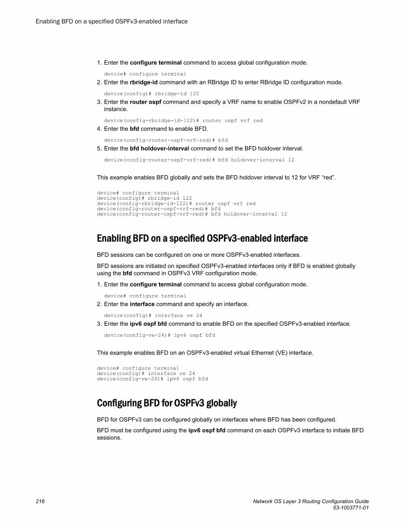
1. Enter the configure terminal command to access global configuration mode.
device# configure terminal2. Enter the rbridge-id command with an RBridge ID to enter RBridge ID configuration mode.
device(config)# rbridge-id 1223. Enter the router ospf command and specify a VRF name to enable OSPFv2 in a nondefault VRF
instance.
device(config-rbridge-id-122)# router ospf vrf red4. Enter the bfd command to enable BFD.
device(config-router-ospf-vrf-red)# bfd 5. Enter the bfd holdover-interval command to set the BFD holdover interval.
device(config-router-ospf-vrf-red)# bfd holdover-interval 12
This example enables BFD globally and sets the BFD holdover interval to 12 for VRF “red”.
device# configure terminaldevice(config)# rbridge-id 122device(config-rbridge-id-122)# router ospf vrf reddevice(config-router-ospf-vrf-red)# bfd device(config-router-ospf-vrf-red)# bfd holdover-interval 12
Enabling BFD on a specified OSPFv3-enabled interfaceBFD sessions can be configured on one or more OSPFv3-enabled interfaces.
BFD sessions are initiated on specified OSPFv3-enabled interfaces only if BFD is enabled globallyusing the bfd command in OSPFv3 VRF configuration mode.
1. Enter the configure terminal command to access global configuration mode.
device# configure terminal2. Enter the interface command and specify an interface.
device(config)# interface ve 243. Enter the ipv6 ospf bfd command to enable BFD on the specified OSPFv3-enabled interface.
device(config-ve-24)# ipv6 ospf bfd
This example enables BFD on an OSPFv3-enabled virtual Ethernet (VE) interface.
device# configure terminaldevice(config)# interface ve 24device(config-ve-24)# ipv6 ospf bfd
Configuring BFD for OSPFv3 globallyBFD for OSPFv3 can be configured globally on interfaces where BFD has been configured.
BFD must be configured using the ipv6 ospf bfd command on each OSPFv3 interface to initiate BFDsessions.
Enabling BFD on a specified OSPFv3-enabled interface
216 Network OS Layer 3 Routing Configuration Guide53-1003771-01
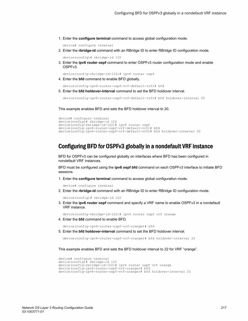
1. Enter the configure terminal command to access global configuration mode.
device# configure terminal2. Enter the rbridge-id command with an RBridge ID to enter RBridge ID configuration mode.
device(config)# rbridge-id 1223. Enter the ipv6 router ospf command to enter OSPFv3 router configuration mode and enable
OSPFv3.
device(config-rbridge-id-122)# ipv6 router ospf4. Enter the bfd command to enable BFD globally.
device(config-ipv6-router-ospf-vrf-default-vrf)# bfd 5. Enter the bfd holdover-interval command to set the BFD holdover interval.
device(config-ipv6-router-ospf-vrf-default-vrf)# bfd holdover-interval 20
This example enables BFD and sets the BFD holdover interval to 20.
device# configure terminaldevice(config)# rbridge-id 122device(config-rbridge-id-122)# ipv6 router ospfdevice(config-ipv6-router-ospf-vrf-default-vrf)# bfd device(config-ipv6-router-ospf-vrf-default-vrf)# bfd holdover-interval 20
Configuring BFD for OSPFv3 globally in a nondefault VRF instanceBFD for OSPFv3 can be configured globally on interfaces where BFD has been configured innondefault VRF instances.
BFD must be configured using the ipv6 ospf bfd command on each OSPFv3 interface to initiate BFDsessions.
1. Enter the configure terminal command to access global configuration mode.
device# configure terminal2. Enter the rbridge-id command with an RBridge ID to enter RBridge ID configuration mode.
device(config)# rbridge-id 1223. Enter the ipv6 router ospf command and specify a VRF name to enable OSPFv3 in a nondefault
VRF instance.
device(config-rbridge-id-122)# ipv6 router ospf vrf orange4. Enter the bfd command to enable BFD.
device(config-ipv6-router-ospf-vrf-orange)# bfd 5. Enter the bfd holdover-interval command to set the BFD holdover interval.
device(config-ipv6-router-ospf-vrf-orange)# bfd holdover-interval 22
This example enables BFD and sets the BFD holdover interval to 22 for VRF “orange”.
device# configure terminaldevice(config)# rbridge-id 122device(config-rbridge-id-122)# ipv6 router ospf vrf orangedevice(config-ipv6-router-ospf-vrf-orange)# bfddevice(config-ipv6-router-ospf-vrf-orange)# bfd holdover-interval 22
Configuring BFD for OSPFv3 globally in a nondefault VRF instance
Network OS Layer 3 Routing Configuration Guide 21753-1003771-01

BFD for VXLAN extension tunnelsBFD support for VXLAN extension tunnels can be configured for diagnostic purposes.
VXLAN extension tunnels facilitate a Layer 3 overlay to extend Layer 2 VLANs across VCS clusters.Two different VCS clusters can be connected by a VXLAN tunnel. A VXLAN tunnel can have its endpoints in either VCS, with the possibility of multiple Layer 3 ECMP paths (4 paths) between the endpoints. BFD has the ability to monitor the tunnel for reachability and quick fault detection.
NOTERBridges in a VXLAN Network Identifier (VNI) tunnel endpoint (VTEP) are assumed to be connectedsymmetrically to the destination VTEP. BFD sessions run from all RBridge in the VTEP.
A single BFD session is used to monitor the connectivity of a VXLAN tunnel endpoint. When a tunnelsession is created, an RBridge is selected as the “master RBridge”. This master RBridge runs the fullBFD state machine for the VXLAN tunnel. BFD session information is also created in other RBridges,but these backup RBridges do not run the full state machine for that specific BFD session. TheRBridge with the lowest RBridge ID is selected as the Master RBridge. Furthermore, a newly joinedRBridge with a lower RBridge ID than the current master RBridge can pre-empt the mastership fromthe existing master.
In the figure below, RB1 is the master RBridge for the tunnel session established between the sourceVTEP and the destination VTEP. RBridges RB2 and RB3 are designated as backup RBridges. Thenodes are connected through Inter-Switch Link (ISLs). The participants of the VTEP gateway (RB1,RB2, and RB3) communicate with each other using fabric messages that are transmitted through ISLlinks.
FIGURE 28 BFD for VXLAN extension tunnels
BFD for VXLAN extension tunnels
218 Network OS Layer 3 Routing Configuration Guide53-1003771-01
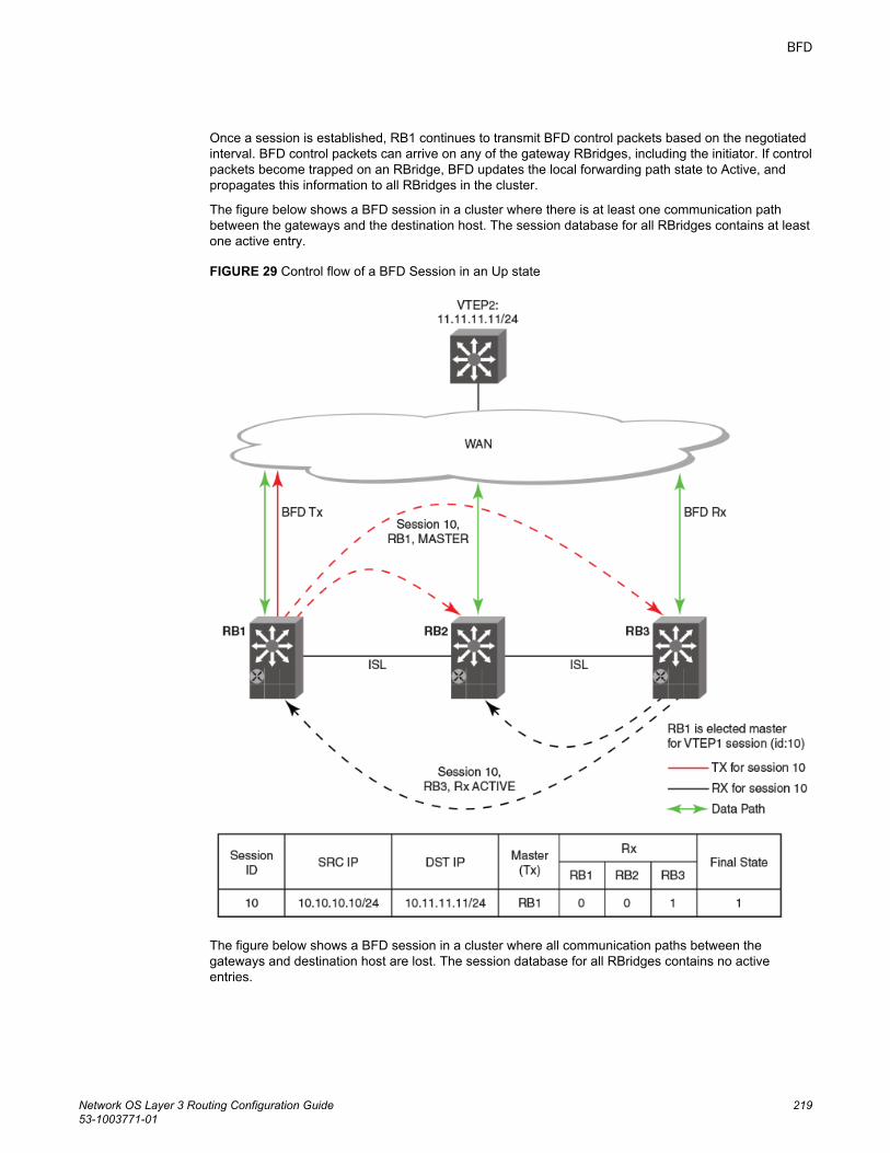
Once a session is established, RB1 continues to transmit BFD control packets based on the negotiatedinterval. BFD control packets can arrive on any of the gateway RBridges, including the initiator. If controlpackets become trapped on an RBridge, BFD updates the local forwarding path state to Active, andpropagates this information to all RBridges in the cluster.
The figure below shows a BFD session in a cluster where there is at least one communication pathbetween the gateways and the destination host. The session database for all RBridges contains at leastone active entry.
FIGURE 29 Control flow of a BFD Session in an Up state
The figure below shows a BFD session in a cluster where all communication paths between thegateways and destination host are lost. The session database for all RBridges contains no activeentries.
BFD
Network OS Layer 3 Routing Configuration Guide 21953-1003771-01
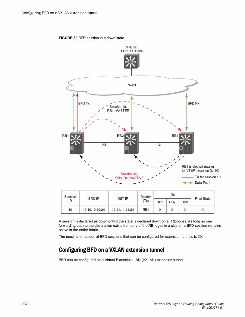
FIGURE 30 BFD session in a down state
A session is declared as down only if the state is declared down on all RBridges. As long as oneforwarding path to the destination exists from any of the RBridges in a cluster, a BFD session remainsactive in the entire fabric.
The maximum number of BFD sessions that can be configured for extension tunnels is 20.
Configuring BFD on a VXLAN extension tunnelBFD can be configured on a Virtual Extensible LAN (VXLAN) extension tunnel.
Configuring BFD on a VXLAN extension tunnel
220 Network OS Layer 3 Routing Configuration Guide53-1003771-01
1. Enter the configure terminal command to access global configuration mode.
device# configure terminal2. Enter the overlay-gateway command and specify a name to create a VXLAN overlay gateway
instance and enter VXLAN overlay gateway configuration mode.
device(config)# overlay-gateway gateway13. Enter the type command using the layer2-extension keyword to specify that the VXLAN overlay
gateway uses Layer 2 extension.
device(config-overlay-gw-gateway1)# type layer2-extension4. Enter the ip interface command using the loopback keyword to specify an IPv4 loopback interface.
device(config-overlay-gw-gateway1)# ip interface loopback 225. Enter the site command and specify a name to create a remote Layer 2 extension site in a VXLAN
overlay gateway context and enable VXLAN overlay gateway site configuration mode.
device(config-overlay-gw-gateway1)# site s16. Enter the ip address command to specify the destination IPv4 address of the tunnel.
device(config-site-s1)# ip address 10.11.12.137. Enter the bfd command to enable BFD on the VXLAN overlay gateway site.
device(config-site-s1)# bfd8. Enter the bfd interval command with the min-rx and multiplier keywords to set the BFD session
parameters on the VXLAN overlay gateway site.
device(config-site-s1)# bfd interval 2000 min-rx 3000 multiplier 26
This example enables BFD on the VXLAN overlay gateway site and sets the BFD session parameters.
device# configure terminaldevice(config)# overlay-gateway gateway1device(config-overlay-gw-gateway1)# type layer2-extensiondevice(config-overlay-gw-gateway1)# ip interface loopback 22device(config-overlay-gw-gateway1)# site s1device(config-site-s1)# ip address 10.11.12.13device(config-site-s1)# bfddevice(config-site-s1)# bfd interval 2000 min-rx 3000 multiplier 26
BFD for NSX tunnelsBFD support for NSX tunnels can be configured on the Brocade VDX 6740.
An NSX controller expects a VXLAN Network Identifier (VNI) tunnel endpoint (VTEP) to use BFD todetermine the reachability of service node VTEPs at the end of the tunnels. The VTEP is expected touse this information to determine if the tunnel is a healthy service node for sending egress BUM traffic.
In a NSX logical network there can be multiple service nodes for redundancy. For a VTEP, ingress BUMtraffic can arrive from any service node but egress traffic is sent only to one of the service nodes. TheVTEP is responsible for this egress service node selection. Without BFD, one of the service nodes israndomly selected and is never changed unless the tunnel is deleted by the NSX controller.
With BFD, the health of all severvice nodes can be monitored. If the BFD status of the BUM-enabledservice node is reported as Down, another service node tunnel with a BFD status of Up is selected.Details of the BUM-enabled service node tunnel can be printed using the show tunnel command. Referto the Network OS Command Reference for more information on this command.
BFD for NSX tunnels
Network OS Layer 3 Routing Configuration Guide 22153-1003771-01
NOTEBFD parameters are not configurable in switches for VXLAN NSX.
For more information on NSX tunnels, refer to the Network OS Layer 2 Switching Configuration Guide.
NOTEOpen vSwitch hardware_vtep v1.3.0 schema support is required on VTEP switches for using BFD in aNSX logical network.
BFD for static routesUnlike dynamic routing protocols, such as OSPF and BGP, static routing has no method of peerdiscovery and fault detection. BFD for IPv4 and IPv6 static routes provides rapid detection of failure inthe bidirectional forwarding path between BFD peers.
BFD for Static Routes allows you to detect failures that impact the forwarding path of a static route.This feature supports both singlehop and multihop BFD Static Routes for both IPv4 and IPv6. Unlessthe BFD session is up, the gateway for the static route is considered unreachable, and the affectedroutes are not installed in the routing table. BFD can remove the associated static route from therouting table if the next-hop becomes unreachable indicating that the BFD session has gone down.
Static routes and BFD neighbors are configured separately. A static route is automatically associatedwith a static BFD neighbor if the static route’s next-hop exactly matches the neighbor address of thestatic BFD neighbor and BFD monitoring is enabled for the static route.
When a static BFD neighbor is configured, BFD asks the routing table manager if there is a route tothe BFD neighbor. If a route exists, and if next-hop is directly connected, BFD initiates a singlehopsession. If the next-hop is not directly connected, BFD establishes a multihop session.
When a BFD session goes down because the BFD neighbor is no longer reachable, static routesmonitored by BFD are removed from the routing table manager. The removed routes can be addedback if the BFD neighbor becomes reachable again. Singlehop BFD sessions use the BFD timeoutvalues configured on the outgoing interface. Timeout values for multihop BFD sessions are specifiedalong with each BFD neighbor. Multiple static routes going to the same BFD neighbor use the sameBFD session and timeout values.
BFD considerations and limitations for static routesThere are a number of things to consider when configuring BFD for IPv4 and IPv6 static routes.
Refer to the BFD chapter for more information on BFD considerations and limitations.
BFD considerations and limitations for static routes• BFD is not supported on interface-based static routes because BFD requires that the next-hop
address matches the address of the BFD neighbor.• Only one static route BFD session for a neighbor is created at any instance. This is always based
on the best path for the neighbor.• Static BFD for a multihop BFD neighbor reachable via Equal Cost Multiple Paths (ECMP) is not
supported. Static BFD needs to be configured explicitly for each next-hop corresponding to eachpath.
BFD for static routes
222 Network OS Layer 3 Routing Configuration Guide53-1003771-01
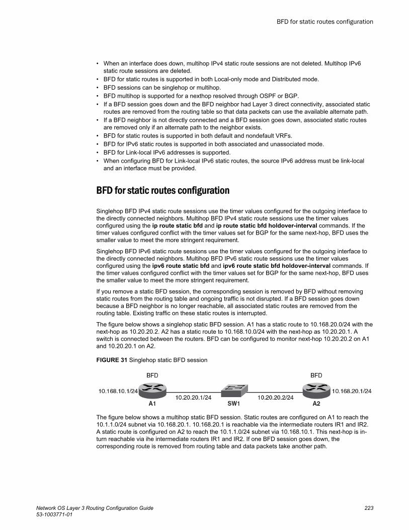
• When an interface does down, multihop IPv4 static route sessions are not deleted. Multihop IPv6static route sessions are deleted.
• BFD for static routes is supported in both Local-only mode and Distributed mode.• BFD sessions can be singlehop or multihop.• BFD multihop is supported for a nexthop resolved through OSPF or BGP.• If a BFD session goes down and the BFD neighbor had Layer 3 direct connectivity, associated static
routes are removed from the routing table so that data packets can use the available alternate path.• If a BFD neighbor is not directly connected and a BFD session goes down, associated static routes
are removed only if an alternate path to the neighbor exists.• BFD for static routes is supported in both default and nondefault VRFs.• BFD for IPv6 static routes is supported in both associated and unassociated mode.• BFD for Link-local IPv6 addresses is supported.• When configuring BFD for Link-local IPv6 static routes, the source IPv6 address must be link-local
and an interface must be provided.
BFD for static routes configuration
Singlehop BFD IPv4 static route sessions use the timer values configured for the outgoing interface tothe directly connected neighbors. Multihop BFD IPv4 static route sessions use the timer valuesconfigured using the ip route static bfd and ip route static bfd holdover-interval commands. If thetimer values configured conflict with the timer values set for BGP for the same next-hop, BFD uses thesmaller value to meet the more stringent requirement.
Singlehop BFD IPv6 static route sessions use the timer values configured for the outgoing interface tothe directly connected neighbors. Multihop BFD IPv6 static route sessions use the timer valuesconfigured using the ipv6 route static bfd and ipv6 route static bfd holdover-interval commands. Ifthe timer values configured conflict with the timer values set for BGP for the same next-hop, BFD usesthe smaller value to meet the more stringent requirement.
If you remove a static BFD session, the corresponding session is removed by BFD without removingstatic routes from the routing table and ongoing traffic is not disrupted. If a BFD session goes downbecause a BFD neighbor is no longer reachable, all associated static routes are removed from therouting table. Existing traffic on these static routes is interrupted.
The figure below shows a singlehop static BFD session. A1 has a static route to 10.168.20.0/24 with thenext-hop as 10.20.20.2. A2 has a static route to 10.168.10.0/24 with the next-hop as 10.20.20.1. Aswitch is connected between the routers. BFD can be configured to monitor next-hop 10.20.20.2 on A1and 10.20.20.1 on A2.
FIGURE 31 Singlehop static BFD session
The figure below shows a multihop static BFD session. Static routes are configured on A1 to reach the10.1.1.0/24 subnet via 10.168.20.1. 10.168.20.1 is reachable via the intermediate routers IR1 and IR2.A static route is configured on A2 to reach the 10.1.1.0/24 subnet via 10.168.10.1. This next-hop is in-turn reachable via ihe intermediate routers IR1 and IR2. If one BFD session goes down, thecorresponding route is removed from routing table and data packets take another path.
BFD for static routes configuration
Network OS Layer 3 Routing Configuration Guide 22353-1003771-01
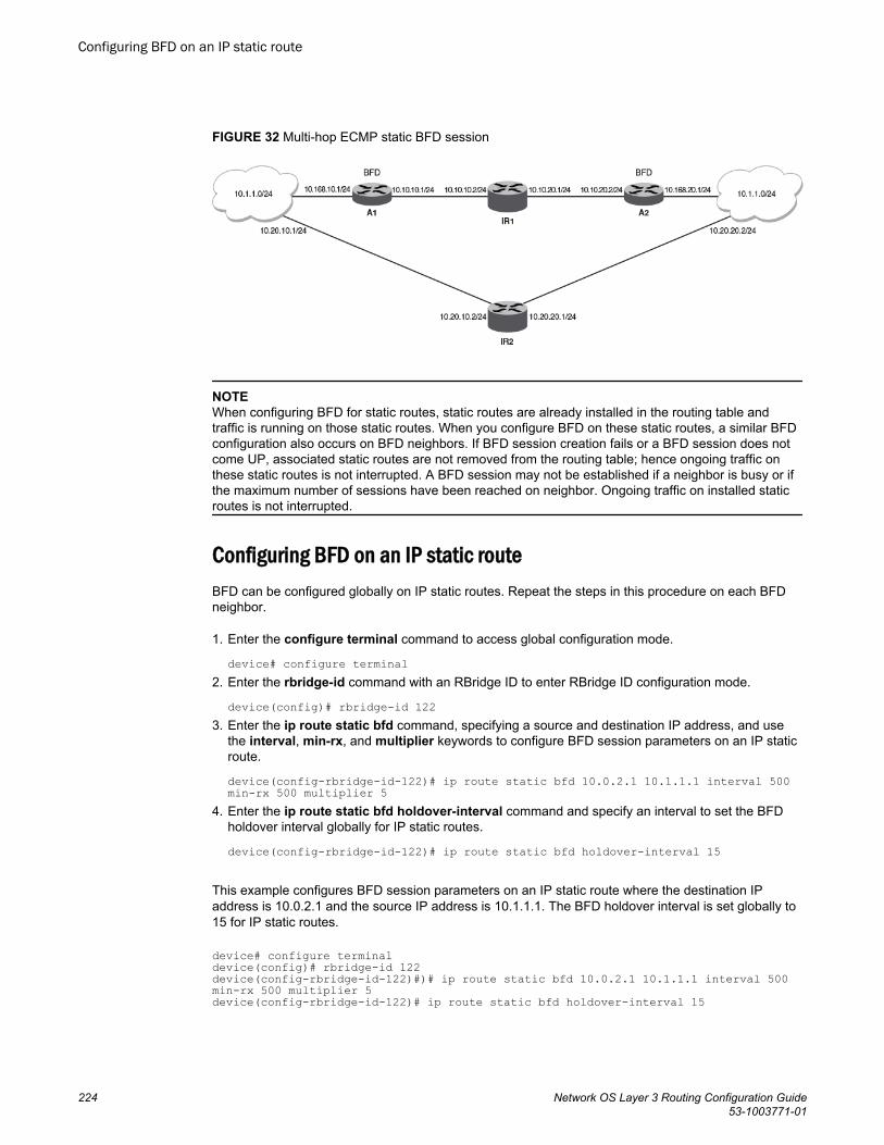
FIGURE 32 Multi-hop ECMP static BFD session
NOTEWhen configuring BFD for static routes, static routes are already installed in the routing table andtraffic is running on those static routes. When you configure BFD on these static routes, a similar BFDconfiguration also occurs on BFD neighbors. If BFD session creation fails or a BFD session does notcome UP, associated static routes are not removed from the routing table; hence ongoing traffic onthese static routes is not interrupted. A BFD session may not be established if a neighbor is busy or ifthe maximum number of sessions have been reached on neighbor. Ongoing traffic on installed staticroutes is not interrupted.
Configuring BFD on an IP static routeBFD can be configured globally on IP static routes. Repeat the steps in this procedure on each BFDneighbor.
1. Enter the configure terminal command to access global configuration mode.
device# configure terminal2. Enter the rbridge-id command with an RBridge ID to enter RBridge ID configuration mode.
device(config)# rbridge-id 1223. Enter the ip route static bfd command, specifying a source and destination IP address, and use
the interval, min-rx, and multiplier keywords to configure BFD session parameters on an IP staticroute.
device(config-rbridge-id-122)# ip route static bfd 10.0.2.1 10.1.1.1 interval 500 min-rx 500 multiplier 5
4. Enter the ip route static bfd holdover-interval command and specify an interval to set the BFDholdover interval globally for IP static routes.
device(config-rbridge-id-122)# ip route static bfd holdover-interval 15
This example configures BFD session parameters on an IP static route where the destination IPaddress is 10.0.2.1 and the source IP address is 10.1.1.1. The BFD holdover interval is set globally to15 for IP static routes.
device# configure terminaldevice(config)# rbridge-id 122device(config-rbridge-id-122)#)# ip route static bfd 10.0.2.1 10.1.1.1 interval 500 min-rx 500 multiplier 5 device(config-rbridge-id-122)# ip route static bfd holdover-interval 15
Configuring BFD on an IP static route
224 Network OS Layer 3 Routing Configuration Guide53-1003771-01
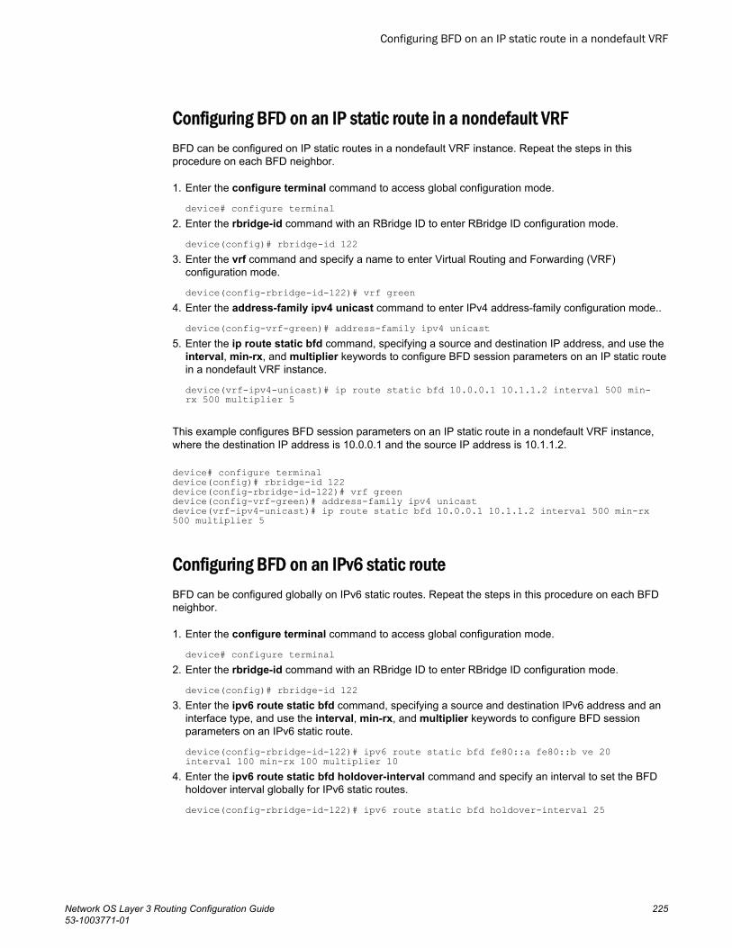
Configuring BFD on an IP static route in a nondefault VRFBFD can be configured on IP static routes in a nondefault VRF instance. Repeat the steps in thisprocedure on each BFD neighbor.
1. Enter the configure terminal command to access global configuration mode.
device# configure terminal2. Enter the rbridge-id command with an RBridge ID to enter RBridge ID configuration mode.
device(config)# rbridge-id 1223. Enter the vrf command and specify a name to enter Virtual Routing and Forwarding (VRF)
configuration mode.
device(config-rbridge-id-122)# vrf green4. Enter the address-family ipv4 unicast command to enter IPv4 address-family configuration mode..
device(config-vrf-green)# address-family ipv4 unicast5. Enter the ip route static bfd command, specifying a source and destination IP address, and use the
interval, min-rx, and multiplier keywords to configure BFD session parameters on an IP static routein a nondefault VRF instance.
device(vrf-ipv4-unicast)# ip route static bfd 10.0.0.1 10.1.1.2 interval 500 min-rx 500 multiplier 5
This example configures BFD session parameters on an IP static route in a nondefault VRF instance,where the destination IP address is 10.0.0.1 and the source IP address is 10.1.1.2.
device# configure terminaldevice(config)# rbridge-id 122device(config-rbridge-id-122)# vrf greendevice(config-vrf-green)# address-family ipv4 unicastdevice(vrf-ipv4-unicast)# ip route static bfd 10.0.0.1 10.1.1.2 interval 500 min-rx 500 multiplier 5
Configuring BFD on an IPv6 static routeBFD can be configured globally on IPv6 static routes. Repeat the steps in this procedure on each BFDneighbor.
1. Enter the configure terminal command to access global configuration mode.
device# configure terminal2. Enter the rbridge-id command with an RBridge ID to enter RBridge ID configuration mode.
device(config)# rbridge-id 1223. Enter the ipv6 route static bfd command, specifying a source and destination IPv6 address and an
interface type, and use the interval, min-rx, and multiplier keywords to configure BFD sessionparameters on an IPv6 static route.
device(config-rbridge-id-122)# ipv6 route static bfd fe80::a fe80::b ve 20 interval 100 min-rx 100 multiplier 10
4. Enter the ipv6 route static bfd holdover-interval command and specify an interval to set the BFDholdover interval globally for IPv6 static routes.
device(config-rbridge-id-122)# ipv6 route static bfd holdover-interval 25
Configuring BFD on an IP static route in a nondefault VRF
Network OS Layer 3 Routing Configuration Guide 22553-1003771-01
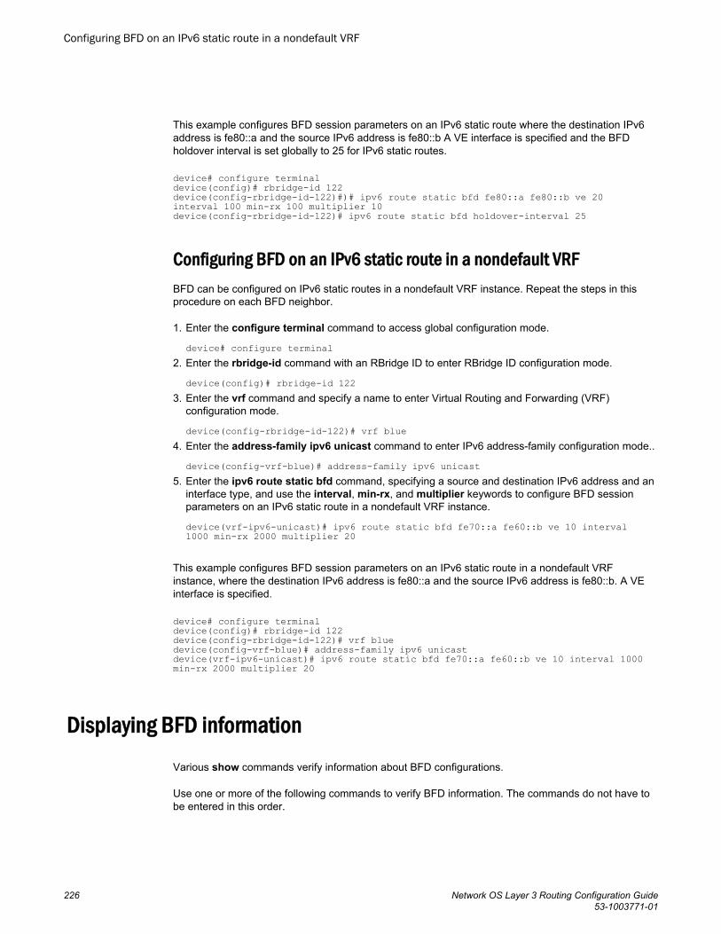
This example configures BFD session parameters on an IPv6 static route where the destination IPv6address is fe80::a and the source IPv6 address is fe80::b A VE interface is specified and the BFDholdover interval is set globally to 25 for IPv6 static routes.
device# configure terminaldevice(config)# rbridge-id 122device(config-rbridge-id-122)#)# ipv6 route static bfd fe80::a fe80::b ve 20 interval 100 min-rx 100 multiplier 10device(config-rbridge-id-122)# ipv6 route static bfd holdover-interval 25
Configuring BFD on an IPv6 static route in a nondefault VRFBFD can be configured on IPv6 static routes in a nondefault VRF instance. Repeat the steps in thisprocedure on each BFD neighbor.
1. Enter the configure terminal command to access global configuration mode.
device# configure terminal2. Enter the rbridge-id command with an RBridge ID to enter RBridge ID configuration mode.
device(config)# rbridge-id 1223. Enter the vrf command and specify a name to enter Virtual Routing and Forwarding (VRF)
configuration mode.
device(config-rbridge-id-122)# vrf blue4. Enter the address-family ipv6 unicast command to enter IPv6 address-family configuration mode..
device(config-vrf-blue)# address-family ipv6 unicast5. Enter the ipv6 route static bfd command, specifying a source and destination IPv6 address and an
interface type, and use the interval, min-rx, and multiplier keywords to configure BFD sessionparameters on an IPv6 static route in a nondefault VRF instance.
device(vrf-ipv6-unicast)# ipv6 route static bfd fe70::a fe60::b ve 10 interval 1000 min-rx 2000 multiplier 20
This example configures BFD session parameters on an IPv6 static route in a nondefault VRFinstance, where the destination IPv6 address is fe80::a and the source IPv6 address is fe80::b. A VEinterface is specified.
device# configure terminaldevice(config)# rbridge-id 122device(config-rbridge-id-122)# vrf bluedevice(config-vrf-blue)# address-family ipv6 unicastdevice(vrf-ipv6-unicast)# ipv6 route static bfd fe70::a fe60::b ve 10 interval 1000 min-rx 2000 multiplier 20
Displaying BFD informationVarious show commands verify information about BFD configurations.
Use one or more of the following commands to verify BFD information. The commands do not have tobe entered in this order.
Configuring BFD on an IPv6 static route in a nondefault VRF
226 Network OS Layer 3 Routing Configuration Guide53-1003771-01
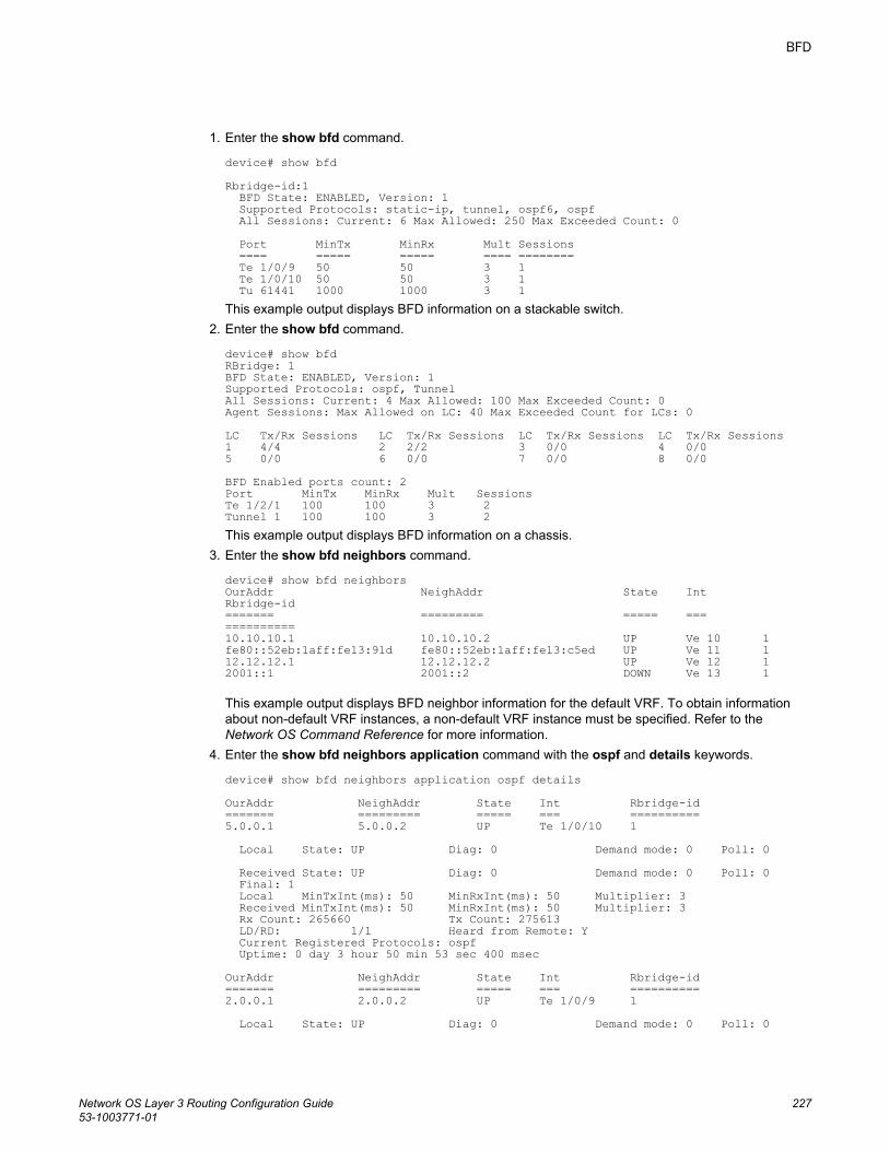
1. Enter the show bfd command.
device# show bfdRbridge-id:1 BFD State: ENABLED, Version: 1 Supported Protocols: static-ip, tunnel, ospf6, ospf All Sessions: Current: 6 Max Allowed: 250 Max Exceeded Count: 0 Port MinTx MinRx Mult Sessions ==== ===== ===== ==== ======== Te 1/0/9 50 50 3 1 Te 1/0/10 50 50 3 1 Tu 61441 1000 1000 3 1This example output displays BFD information on a stackable switch.
2. Enter the show bfd command.
device# show bfd RBridge: 1 BFD State: ENABLED, Version: 1 Supported Protocols: ospf, Tunnel All Sessions: Current: 4 Max Allowed: 100 Max Exceeded Count: 0 Agent Sessions: Max Allowed on LC: 40 Max Exceeded Count for LCs: 0 LC Tx/Rx Sessions LC Tx/Rx Sessions LC Tx/Rx Sessions LC Tx/Rx Sessions 1 4/4 2 2/2 3 0/0 4 0/0 5 0/0 6 0/0 7 0/0 8 0/0 BFD Enabled ports count: 2 Port MinTx MinRx Mult Sessions Te 1/2/1 100 100 3 2 Tunnel 1 100 100 3 2 This example output displays BFD information on a chassis.
3. Enter the show bfd neighbors command.
device# show bfd neighborsOurAddr NeighAddr State Int Rbridge-id======= ========= ===== === ==========10.10.10.1 10.10.10.2 UP Ve 10 1fe80::52eb:1aff:fe13:91d fe80::52eb:1aff:fe13:c5ed UP Ve 11 112.12.12.1 12.12.12.2 UP Ve 12 12001::1 2001::2 DOWN Ve 13 1
This example output displays BFD neighbor information for the default VRF. To obtain informationabout non-default VRF instances, a non-default VRF instance must be specified. Refer to theNetwork OS Command Reference for more information.
4. Enter the show bfd neighbors application command with the ospf and details keywords.
device# show bfd neighbors application ospf details OurAddr NeighAddr State Int Rbridge-id======= ========= ===== === ========== 5.0.0.1 5.0.0.2 UP Te 1/0/10 1 Local State: UP Diag: 0 Demand mode: 0 Poll: 0 Received State: UP Diag: 0 Demand mode: 0 Poll: 0 Final: 1 Local MinTxInt(ms): 50 MinRxInt(ms): 50 Multiplier: 3 Received MinTxInt(ms): 50 MinRxInt(ms): 50 Multiplier: 3 Rx Count: 265660 Tx Count: 275613 LD/RD: 1/1 Heard from Remote: Y Current Registered Protocols: ospf Uptime: 0 day 3 hour 50 min 53 sec 400 msecOurAddr NeighAddr State Int Rbridge-id======= ========= ===== === ========== 2.0.0.1 2.0.0.2 UP Te 1/0/9 1 Local State: UP Diag: 0 Demand mode: 0 Poll: 0
BFD
Network OS Layer 3 Routing Configuration Guide 22753-1003771-01
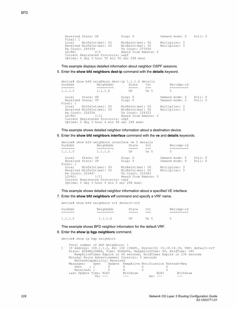
Received State: UP Diag: 0 Demand mode: 0 Poll: 0 Final: 1 Local MinTxInt(ms): 50 MinRxInt(ms): 50 Multiplier: 3 Received MinTxInt(ms): 50 MinRxInt(ms): 50 Multiplier: 3 Rx Count: 265559 Tx Count: 275550 LD/RD: 2/3 Heard from Remote: Y Current Registered Protocols: ospf Uptime: 0 day 3 hour 50 min 50 sec 248 msec
This example displays detailed information about neighbor OSPF sessions.5. Enter the show bfd neighbors dest-ip command with the details keyword.
device# show bfd neighbors dest-ip 1.1.1.6 detailsOurAddr NeighAddr State Int Rbridge-id======= ========= ===== === ========== 1.1.1.5 1.1.1.6 UP Ve 5 5 Local State: UP Diag: 0 Demand mode: 0 Poll: 0 Received State: UP Diag: 0 Demand mode: 0 Poll: 0 Final: 1 Local MinTxInt(ms): 50 MinRxInt(ms): 50 Multiplier: 3 Received MinTxInt(ms): 50 MinRxInt(ms): 50 Multiplier: 3 Rx Count: 226354 Tx Count: 234323 LD/RD: 1/11 Heard from Remote: Y Current Registered Protocols: ospf Uptime: 0 day 3 hour 4 min 48 sec 248 msec
This example shows detailed neighbor information about a destination device.6. Enter the show bfd neighbors interface command with the ve and details keywords.
device# show bfd neighbors interface ve 5 detailsOurAddr NeighAddr State Int Rbridge-id======= ========= ===== === ========== 1.1.1.5 1.1.1.6 UP Ve 5 5 Local State: UP Diag: 0 Demand mode: 0 Poll: 0 Received State: UP Diag: 0 Demand mode: 0 Poll: 0 Final: 1 Local MinTxInt(ms): 50 MinRxInt(ms): 50 Multiplier: 3 Received MinTxInt(ms): 50 MinRxInt(ms): 50 Multiplier: 3 Rx Count: 225447 Tx Count: 233383 LD/RD: 1/11 Heard from Remote: Y Current Registered Protocols: ospf Uptime: 0 day 3 hour 4 min 0 sec 208 msec
This example shows detailed neighbor information about a specified VE interface.7. Enter the show bfd neighbors vrf command and specify a VRF name.
device# show bfd neighbors vrf default-vrfOurAddr NeighAddr State Int Rbridge-id======= ========= ===== === ========== 1.1.1.5 1.1.1.6 UP Ve 5 5
This example shows BFD neighbor information for the default VRF.8. Enter the show ip bgp neighbors command.
device# show ip bgp neighbors Total number of BGP Neighbors: 11 IP Address: 100.1.1.2, AS: 100 (IBGP), RouterID: 19.19.19.19, VRF: default-vrf State: ESTABLISHED, Time: 0h6m49s, KeepAliveTime: 60, HoldTime: 180 KeepAliveTimer Expire in 44 seconds, HoldTimer Expire in 136 seconds Minimal Route Advertisement Interval: 0 seconds RefreshCapability: Received Messages: Open Update KeepAlive Notification Refresh-Req Sent : 1 0 9 0 0 Received: 1 0 8 0 0 Last Update Time: NLRI Withdraw NLRI Withdraw Tx: --- --- Rx: --- ---
BFD
228 Network OS Layer 3 Routing Configuration Guide53-1003771-01
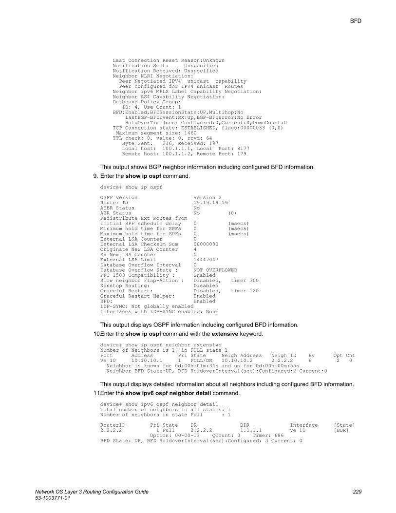
Last Connection Reset Reason:Unknown Notification Sent: Unspecified Notification Received: Unspecified Neighbor NLRI Negotiation: Peer Negotiated IPV4 unicast capability Peer configured for IPV4 unicast Routes Neighbor ipv6 MPLS Label Capability Negotiation: Neighbor AS4 Capability Negotiation: Outbound Policy Group: ID: 4, Use Count: 1 BFD:Enabled,BFDSessionState:UP,Multihop:No LastBGP-BFDEvent:RX:Up,BGP-BFDError:No Error HoldOverTime(sec) Configured:0,Current:0,DownCount:0 TCP Connection state: ESTABLISHED, flags:00000033 (0,0) Maximum segment size: 1460 TTL check: 0, value: 0, rcvd: 64 Byte Sent: 216, Received: 197 Local host: 100.1.1.1, Local Port: 8177 Remote host: 100.1.1.2, Remote Port: 179
This output shows BGP neighbor information including configured BFD information.9. Enter the show ip ospf command.
device# show ip ospf OSPF Version Version 2 Router Id 19.19.19.19 ASBR Status No ABR Status No (0)Redistribute Ext Routes from Initial SPF schedule delay 0 (msecs)Minimum hold time for SPFs 0 (msecs)Maximum hold time for SPFs 0 (msecs)External LSA Counter 0 External LSA Checksum Sum 00000000 Originate New LSA Counter 4 Rx New LSA Counter 5 External LSA Limit 14447047 Database Overflow Interval 0 Database Overflow State : NOT OVERFLOWED RFC 1583 Compatibility : Enabled Slow neighbor Flap-Action : Disabled, timer 300Nonstop Routing: Disabled Graceful Restart: Disabled, timer 120Graceful Restart Helper: EnabledBFD: EnabledLDP-SYNC: Not globally enabledInterfaces with LDP-SYNC enabled: None
This output displays OSPF information including configured BFD information.10.Enter the show ip ospf command with the extensive keyword.
device# show ip ospf neighbor extensiveNumber of Neighbors is 1, in FULL state 1Port Address Pri State Neigh Address Neigh ID Ev Opt CntVe 10 10.10.10.1 1 FULL/DR 10.10.10.2 2.2.2.2 6 2 0 Neighbor is known for 0d:00h:01m:34s and up for 0d:00h:00m:55s Neighbor BFD State:UP, BFD HoldoverInterval(sec):Configured:2 Current:0
This output displays detailed information about all neighbors including configured BFD information.11.Enter the show ipv6 ospf neighbor detail command.
device# show ipv6 ospf neighbor detailTotal number of neighbors in all states: 1Number of neighbors in state Full : 1RouterID Pri State DR BDR Interface [State]2.2.2.2 1 Full 2.2.2.2 1.1.1.1 Ve 11 [BDR] Option: 00-00-13 QCount: 0 Timer: 686BFD State: UP, BFD HoldoverInterval(sec):Configured: 3 Current: 0
BFD
Network OS Layer 3 Routing Configuration Guide 22953-1003771-01
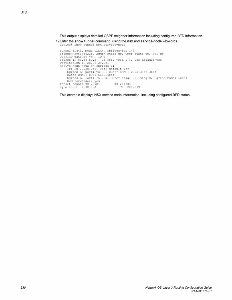
This output displays detailed OSPF neighbor information including configured BFD information.12.Enter the show tunnel command, using the nsx and service-node keywords.
device# show tunnel nsx service-nodeTunnel 61441, mode VXLAN, rbridge-ids 1-2Ifindex 2080436225, Admin state up, Oper state up, BFD upOverlay gateway "k", ID 1Source IP 50.50.50.3 ( Ve 555, Vrid 1 ), Vrf default-vrfDestination IP 20.20.20.251Active next hops on rbridge 1: IP: 20.20.20.251, Vrf: default-vrf Egress L3 port: Ve 20, Outer SMAC: 0005.3365.381f Outer DMAC: 0050.5682.48e4 Egress L2 Port: Po 200, Outer ctag: 20, stag:0, Egress mode: Local BUM forwarder: yesPacket count: RX 20701 TX 264784Byte count : RX (NA) TX 62217299 This example displays NSX service node information, including configured BFD status.
BFD
230 Network OS Layer 3 Routing Configuration Guide53-1003771-01
Fabric-Virtual-Gateway
● Fabric-Virtual-Gateway overview.................................................................................. 231● Fabric-Virtual-Gateway limitations................................................................................ 232● Gateway behavior per RBridge..................................................................................... 232● Fabric-Virtual-Gateway configuration notes.................................................................. 233● Fabric-Virtual-Gateway configuration............................................................................235
Fabric-Virtual-Gateway overviewFabric-Virtual-Gateway is a Brocade-proprietary implementation of a router redundancy protocol thatenables Brocade VCS Fabrics to support scalable Layer 3 gateway configuration requirements.
The Fabric-Virtual-Gateway feature allows multiple RBridges in a VCS Fabric to form a group ofgateway routers and share the same gateway IP address for a given subnet. The gateway IP address issimilar to a virtual IP address in VRRP terminology. The gateway IP address can be configured on allthe nodes forming a Fabric-Virtual-Gateway group without the need to assign a unique IP address oneach of the RBridges for a given subnet. Only one gateway IP address is allowed per subnet.
Fabric-Virtual-Gateway does not exchange any advertisements or keepalive frames over the network toor from the group, or detect when the RBridge acting as an ARP responder is down. Instead, itleverages the Brocade-proprietary VCS Fabric services to exchange Fabric-Virtual-Gateway groupinformation among the participating nodes.
Fabric-Virtual-Gateway is configured on a global virtual Ethernet (VE) interface so that all participatingnodes forming the Fabric-Virtual-Gateway redundant group have the same gateway address.
Fabric-Virtual-Gateway provides the following:
• A mechanism to configure IPv4 or IPv6 gateways for each Layer 3 VE interface in a VCS Fabric• Active-active gateway load-balancing• A mechanism that does not require configuring a primary IP address on the Layer 3 interface to
enable gateway functionality• Support for configuring a large number of Layer 3 gateways, and the capability for future expansion
Within a Fabric-Virtual-Gateway group, only one participant RBridge for a given subnet responds toARP requests for the gateway IP address. The Fabric-Virtual-Gateway group master (ARP responder)is elected once during the configuration, and the master takes the responsibility for responding to ARPrequests. The Fabric-Virtual-Gateway group master does not change dynamically and is elected onlywhen the existing master leaves the group or VCS Fabric.
There is no explicit configuration to elect a node as the ARP responder for the gateway IP address.
Network OS Layer 3 Routing Configuration Guide 23153-1003771-01
Fabric-Virtual-Gateway limitationsFabric-Virtual-Gateway has the following limitations:
• Fabric-Virtual-Gateway cannot interoperate with the products of other vendors or Brocade productssuch as the MLX. Fabric-Virtual-Gateway works on Brocade VDX platforms only and does not workon any other platform or with other vendors' products.
• Fabric-Virtual-Gateway is not supported across VCS Fabrics. It is not supported under fabric clusterVCS mode, and is supported only under logical chassis/management cluster modes.
• Fabric-Virtual-Gateway is not compatible with VRRP or VRRP-E, and does not replace or makeVRRP or VRRP-E obsolete. VRRP or VRRP-E will continue to function on Brocade VDX platformswith the present scaling limits.
• A real IP address is required to get a ping response from VCS Fabric hosts in a Fabric-Virtual-Gateway configuration.
Gateway behavior per RBridgeYou can configure load-balancing, minimum priority for a gateway and set the gratuitous ARP timerper RBridge.
• Load balancing
The ARP responder normally routes the traffic. Once the load balancing threshold priority value isexceeded, the device in the network routes the traffic along with the ARP responder.
Load balancing for the gateway virtual MAC address is enabled by default. However, you candisable load balancing.
Load balancing behavior can be controlled on a per-session basis.• Interface tracking
Multiple interfaces can be tracked for a given Fabric-Virtual-Gateway session. In tracking the stateof the interface is tracked (absent , up or in down state).
The threshold priority for acting as a gateway is tracked. If the sum of track priority (the priorityassociated with the element being tracked) goes below the threshold priority specified for loadbalancing, the router relinquishes the ARP responder role and re-election occurs. If the router wasnot elected to be the ARP responder, and load balancing with threshold priority was configured, therouter will not participate in active-active load balancing.
• Network or host tracking
Similar to interface tracking, you can track the availability of a route or the reachability of adestination and can specify the priority associated with each tracked entity.
The next-hop tracking checks for the reachability of the destination.• Gratuitous ARP
By default, periodic gratuitous ARP is disabled for Fabric-Virtual-Gateway.
You can start sending gratuitous ARP packets periodically for all sessions from the Fabric-Virtual-Gateway and enable periodic gratuitous ARP for a specific session.
Fabric-Virtual-Gateway limitations
232 Network OS Layer 3 Routing Configuration Guide53-1003771-01

Fabric-Virtual-Gateway configuration notes
Enabling Fabric-Virtual-Gateway in the VCS FabricFabric-Virtual-Gateway must first be enabled in the VCS Fabric, by means of the router fabric-virtual-gateway command, before it can be configured on individual VE interfaces, as in the following example:device(config)# router fabric-virtual-gateway device(config-router-fabric-virtual-gateway)# By default, both IPv4 and IPv6 address families are enabled in this way. To disable this, use the noenable command in IPv4 or IPv6 address family configuration mode, respectively, as in the followingexamples.device(config)# router fabric-virtual-gateway device(config-router-fabric-virtual-gateway)# address-family ipv4device(config-address-family-ipv4)# no enabledevice(config)# router fabric-virtual-gateway device(config-router-fabric-virtual-gateway)# address-family ipv6device(config-address-family-ipv6)# no enableWhen the no enable command is issued, the Fabric-Virtual-Gateway configuration for the specifiedaddress family is deactivated on all RBridges in the VCS Fabric. Use the enable command in the aboveconfiguration modes to reactivate Fabric-Virtual-Gateway sessions.
Global VE configurationThe global VE interface mode acts as a template to hold the VE-specific configuration in the VCSFabric. However, it does not provision the VLAN or create a Layer 3 VE interface on the individualRBridges automatically. Before a global VE can be configured, the corresponding VLAN must beconfigured. (Ranging is supported.)
The following example creates a global VE interface: device(config)# interface vlan 5124device(config-Vlan-5124)# exitdevice(config)# interface ve 5124device(config-Ve-5124)# Once a global VE interface is created, it can be attached to individual RBridges by means of the attachcommand, as in the following example. Deleting the global VE interface also deletes the correspondingRBridge-level VE interface if it is configured.device(config)# interface ve 5124device(config-Ve-5124)# attach rbridge-id add 1,2,10Attaching a global VE to one or more RBridges, as in the following example, provisions the VLAN onthose Rbridges and automatically creates a Layer 3 VE interface on the specified RBridges. Theremove keyword under the attach command detaches the VE interface from one or more RBridges inthe VCS Fabric.device(config)# interface Ve 5124device(config-interface-ve)# attach rbridge-id remove 1,2Once RBridges are attached to the global VE interface, the administrative enable and disable operationis controlled only from the global VE interface configuration mode. The global VE interface can beadministratively disabled and enabled by means of regular shutdown and no shutdown commandsunder the global VE mode, as in the following example.device(config)# interface ve 5124device(config-Ve-5124)# shutdowndevice(config-Ve-5124)# no shutdown
RBridge-level VE configurationThe Fabric-Virtual-Gateway configuration is available under the RBridge VE interface to control some ofthe parameters of the RBridge. The RBridge-level VE interface configuration works the same way as it
Fabric-Virtual-Gateway configuration notes
Network OS Layer 3 Routing Configuration Guide 23353-1003771-01
does in previous releases. Even if a global VE interface is attached to a specific RBridge, the user canadministratively enable or disable the VE interface under the RBridge, with no effect on the global VEinterface. If the user has already created an RBridge-level VE interface, and later the global VEinterface is attached to the RBridge, the global VE interface shut/no-shut configuration overwrites theRBridge-level configuration. When a global VE interface is either removed or detached from theRBridge, the RBridge-level VE interface is deleted and all user configuration under the RBridge-levelVE interface is lost if that interface does not have an IPv4 or IPv6 address configured.
The RBridge-level VE interface configurations, such as assigning IPv4/IPv6 addresses, proxy ARP,MTU, and so on, are still allowed even when an RBridge is attached to a global VE interface.
Layer 3 Fabric-Virtual-GatewaySimilar to conventional VRRP/VRRP-E, the gateway address for a given subnet must be the same onall of the nodes in the VCS Fabric that participate in the Fabric-Virtual-Gateway group. In the case ofVRRP/VRRP-E, this validation is user-driven, and in case of a misconfiguration multiple gatewayrouters can claim to be the default gateway. With the advent of a global VE interface, and theavailability of gateway IP address configuration only under the global VE interface, the scope ofmanual error is reduced.
A Fabric-Virtual-Gateway configuration, by means of the ip fabric-virtual-gateway or ipv6 fabric-virtual-gateway commands under a global VE interface, acts as template, and is activated only forthose RBridges to which the global VE interface is attached. The following example is a typical Fabric-Virtual-Gateway configuration for both IPv4 and IPv6.device(config)# interface ve 6000device(config-Ve-6000)# attach rbridge-id 10,11,12device(config-Ve-6000)# no shutdowndevice(config-Ve-6000)# ip fabric-virtual-gateway device(config-ip-fabric-virtual-gateway )# gateway-address 10.65.40.100/24device(config-ip-fabric-virtual-gateway )# exitdevice(config-Ve-6000)# ipv6 fabric-virtual-gateway device(config-ipv6-fabric-virtual-gateway )# gateway-address fe80::400/64
Gateway MAC addressThe gateway MAC address is used to respond to ARP requests for a gateway IP address. The defaultIPv4 MAC address is 02e0.5200.01ff. The default IPv6 MAC address is 02e0.5200.02fe.
When Fabric-Virtual-Gateway is configured on multiple VCS Fabrics connected to each other, bydefault all of the VCS Fabrics will use the same gateway MAC address for all of the Fabric-Virtual-Gateway sessions. This leads to multiple IP address being resolved to the same MAC address. Toavoid this, it is necessary to specify a different gateway MAC address for both IPv4 and IPv6 Fabric-Virtual-Gateway sessions in the VCS Fabric. The gateway MAC address can be changed globally forIPv4 and IPv6 address families, as in the following example.device(config)# router fabric-virtual-gateway device(config-router-fabric-virtual-gateway)# address-family ipv4device(config-address-family-ipv4)# gateway-mac-address 00a0.b100.2000device(config-address-family-ipv4)# exitdevice(config-router-fabric-virtual-gateway)# address-family ipv6device(config-address-family-ipv6)# gateway-mac-address 0220.5e00.0012
Note the following considerations:
• The lowest and highest 24 bits cannot be all zeroes in a user-defined gateway MAC address.• Instead of specifying an arbitrary gateway MAC address, the user can pick an address from the
VRRP-E range of MAC address (for example, 02e0.5200.00xx, where xx value be used todifferentiate each VCS Fabric.
• Before configuring or unconfiguring a user-defined gateway MAC address, the address family mustbe disabled administratively. The address family can be disabled by means of the no enablecommand under Fabric-Virtual-Gateway address-family configuration mode.
Fabric-Virtual-Gateway
234 Network OS Layer 3 Routing Configuration Guide53-1003771-01
Enabling or disabling Fabric-Virtual-Gateway sessions on an RBridgeThe administrative state of a session can be flipped on a per-RBridge basis, as it might be necessary todisable or re-enable the Fabric-Virtual-gateway session on selected RBridges.
The following example disables Fabric-Virtual-Gateway for IPv4 address family on an RBridge.device(config)# rbridge-id 2device(config-rbridge-id-2)# interface ve 6000device(config-Ve-6000)# ip fabric-virtual-gatewaydevice(config-ip-fabric-virtual-gateway)# disableUse the no form of the disable command to remove RBridge-level preference. Similarly, when asession is administratively disabled at the global VE interface level, use the enable command underRBridge-level Fabric-Virtual-Gateway configuration mode to enable a sessions on the RBridge. The noform of the disable and enable commands removes the RBridge-level preference with respect to theadministrative state as in the following example.device(config)# rbridge-id 2device(config-rbridge-id-2)# interface ve 6000device(config-Ve-6000)# ip fabric-virtual-gatewaydevice(config-ip-fabric-virtual-gateway)# no disabledevice(config-ip-fabric-virtual-gateway)# no enableWhen neither a disable or enable configuration exists under RBridge-level Fabric-Virtual-Gatewayconfiguration mode, the administrative state of the session is determined by the global VE interfaceconfiguration for Fabric-Virtual-Gateway.
Behaviors specific to Fabric-Virtual-GatewayThe following behaviors are specific to Fabric-Virtual-Gateway:
• Only one Fabric-Virtual-Gateway session is allowed under a VE interface.• Only one gateway address can be specified for a Fabric-Virtual-Gateway session. With IPv6, only
one global scope and one link-local scope address are allowed.• Active-active load balancing is enabled by default. However, it can be disabled globally.• There is no concept of master or backup in active-active configuration. One of the Fabric-Virtual-
Gateway member routers is elected as the default ARP responder.• Only the ARP responder responds to ARP requests for the gateway IP address.• In case active-active load balancing is disabled, only the elected ARP responder acts as the gateway
router, while the remaining Fabric-Virtual-Gateway members forward the traffic to the ARPresponder.
• On all of the RBridges where Fabric-Virtual-Gateway configuration is not activated or applied, thegateway MAC address entry is installed in the hardware to load-balance or forward all gateway trafficto the Fabric-Virtual-Gateway members.
• The ARP responder is re-elected when the existing ARP responder exits the VCS Fabric or theFabric-Virtual-Gateway configuration is detached from the RBridge.
• The ARP responder may be re-elected when active-active load balancing is disabled on an existingARP responder.
Fabric-Virtual-Gateway configurationThe Fabric-Virtual-Gateway configuration consists of three tasks:
1. Enabling router Fabric-Virtual-Gateway
The Fabric-Virtual-Gateway protocol must be enabled in the router address-family before it can beconfigured on individual VE interfaces.
2. Configuring Fabric-Virtual-Gateway on a global VE interface
The following configurations are allowed under global VE interface mode only:
Fabric-Virtual-Gateway configuration
Network OS Layer 3 Routing Configuration Guide 23553-1003771-01
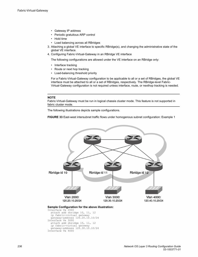
• Gateway IP address• Periodic gratuitous ARP control• Hold time• Load balancing across all RBridges
3. Attaching a global VE interface to specific RBridge(s), and changing the administrative state of theglobal VE interface.
4. Configuring Fabric-Virtual-Gateway in an RBridge VE interface
The following configurations are allowed under the VE interface on an RBridge only:
• Interface tracking• Route or next hop tracking• Load-balancing threshold priority
For a Fabric-Virtual-Gateway configuration to be applicable to all or a set of RBridges, the global VEinterface must be attached to all or a set of RBridges, respectively. The RBridge-level Fabric-Virtual-Gateway configuration is not required unless interface, route, or nexthop tracking is needed.
NOTEFabric-Virtual-Gateway must be run in logical chassis cluster mode. This feature is not supported infabric cluster mode.
The following illustrations depicts sample configurations.
FIGURE 33 East-west intersubnet traffic flows under homogenous subnet configuration: Example 1
Sample Configuration for the above illustration:Interface Ve 2000 attach add rbridge 10, 11, 12 ip fabric-virtual gateway gateway-address 120.20.10.10/24Interface Ve 3000 attach add rbridge 10, 11, 12 ip fabric-virtual gateway gateway-address 120.30.10.10/24Interface Ve 4000
Fabric-Virtual-Gateway
236 Network OS Layer 3 Routing Configuration Guide53-1003771-01
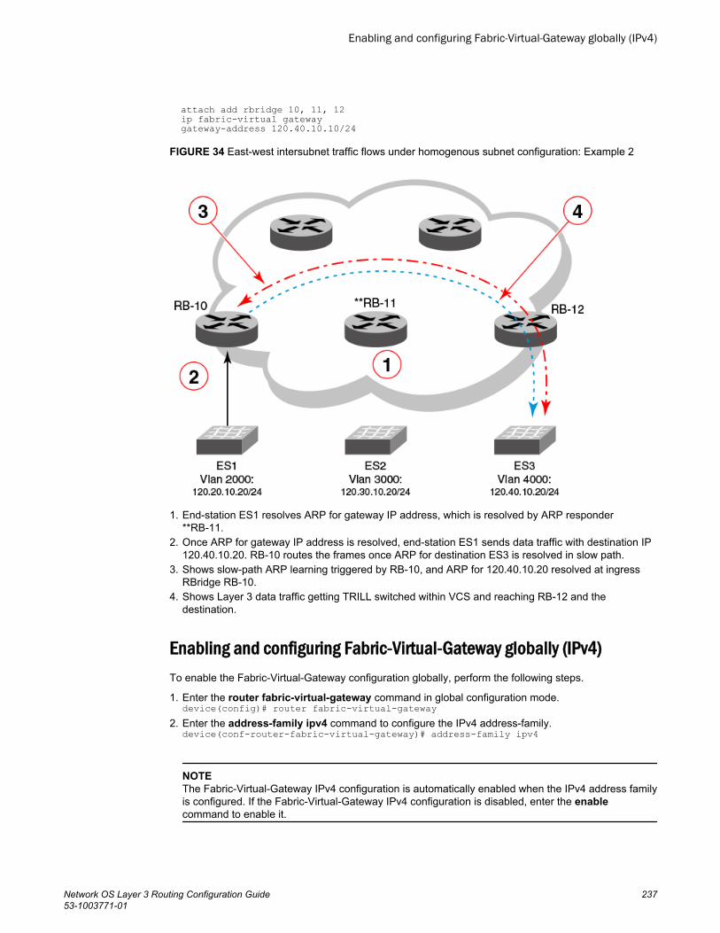
attach add rbridge 10, 11, 12 ip fabric-virtual gateway gateway-address 120.40.10.10/24
FIGURE 34 East-west intersubnet traffic flows under homogenous subnet configuration: Example 2
1. End-station ES1 resolves ARP for gateway IP address, which is resolved by ARP responder**RB-11.
2. Once ARP for gateway IP address is resolved, end-station ES1 sends data traffic with destination IP120.40.10.20. RB-10 routes the frames once ARP for destination ES3 is resolved in slow path.
3. Shows slow-path ARP learning triggered by RB-10, and ARP for 120.40.10.20 resolved at ingressRBridge RB-10.
4. Shows Layer 3 data traffic getting TRILL switched within VCS and reaching RB-12 and thedestination.
Enabling and configuring Fabric-Virtual-Gateway globally (IPv4)To enable the Fabric-Virtual-Gateway configuration globally, perform the following steps.
1. Enter the router fabric-virtual-gateway command in global configuration mode.device(config)# router fabric-virtual-gateway
2. Enter the address-family ipv4 command to configure the IPv4 address-family.device(conf-router-fabric-virtual-gateway)# address-family ipv4
NOTEThe Fabric-Virtual-Gateway IPv4 configuration is automatically enabled when the IPv4 address familyis configured. If the Fabric-Virtual-Gateway IPv4 configuration is disabled, enter the enablecommand to enable it.
Enabling and configuring Fabric-Virtual-Gateway globally (IPv4)
Network OS Layer 3 Routing Configuration Guide 23753-1003771-01
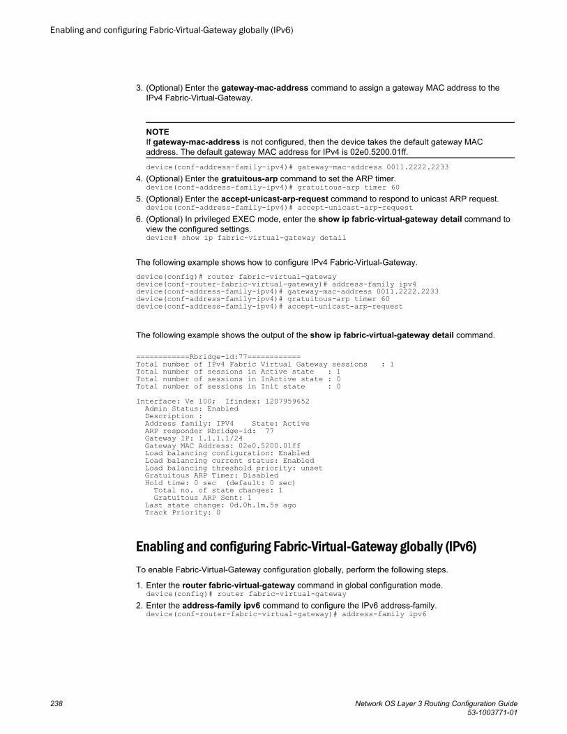
3. (Optional) Enter the gateway-mac-address command to assign a gateway MAC address to theIPv4 Fabric-Virtual-Gateway.
NOTEIf gateway-mac-address is not configured, then the device takes the default gateway MACaddress. The default gateway MAC address for IPv4 is 02e0.5200.01ff.
device(conf-address-family-ipv4)# gateway-mac-address 0011.2222.22334. (Optional) Enter the gratuitous-arp command to set the ARP timer.
device(conf-address-family-ipv4)# gratuitous-arp timer 605. (Optional) Enter the accept-unicast-arp-request command to respond to unicast ARP request.
device(conf-address-family-ipv4)# accept-unicast-arp-request6. (Optional) In privileged EXEC mode, enter the show ip fabric-virtual-gateway detail command to
view the configured settings.device# show ip fabric-virtual-gateway detail
The following example shows how to configure IPv4 Fabric-Virtual-Gateway.device(config)# router fabric-virtual-gatewaydevice(conf-router-fabric-virtual-gateway)# address-family ipv4device(conf-address-family-ipv4)# gateway-mac-address 0011.2222.2233device(conf-address-family-ipv4)# gratuitous-arp timer 60device(conf-address-family-ipv4)# accept-unicast-arp-request
The following example shows the output of the show ip fabric-virtual-gateway detail command.
============Rbridge-id:77============Total number of IPv4 Fabric Virtual Gateway sessions : 1Total number of sessions in Active state : 1Total number of sessions in InActive state : 0Total number of sessions in Init state : 0Interface: Ve 100; Ifindex: 1207959652 Admin Status: Enabled Description : Address family: IPV4 State: Active ARP responder Rbridge-id: 77 Gateway IP: 1.1.1.1/24 Gateway MAC Address: 02e0.5200.01ff Load balancing configuration: Enabled Load balancing current status: Enabled Load balancing threshold priority: unset Gratuitous ARP Timer: Disabled Hold time: 0 sec (default: 0 sec) Total no. of state changes: 1 Gratuitous ARP Sent: 1 Last state change: 0d.0h.1m.5s ago Track Priority: 0
Enabling and configuring Fabric-Virtual-Gateway globally (IPv6)To enable Fabric-Virtual-Gateway configuration globally, perform the following steps.
1. Enter the router fabric-virtual-gateway command in global configuration mode.device(config)# router fabric-virtual-gateway
2. Enter the address-family ipv6 command to configure the IPv6 address-family.device(conf-router-fabric-virtual-gateway)# address-family ipv6
Enabling and configuring Fabric-Virtual-Gateway globally (IPv6)
238 Network OS Layer 3 Routing Configuration Guide53-1003771-01

NOTEThe Fabric-Virtual-Gateway IPv6 configuration is automatically enabled when the IPv6 address familyis configured. If the Fabric-Virtual-Gateway IPv6 configuration is disabled, enter the enablecommand to enable it.
3. (Optional) Enter the gateway-mac-address command to assign a gateway MAC address to the IPv6Fabric-Virtual-Gateway.
NOTEIf gateway-mac-address is not configured, then the device takes the default gateway MAC address.The default gateway MAC address for IPv6 is 02e0.5200.02fe.
device(conf-address-family-ipv6)# gateway-mac-address 0011.2222.22334. (Optional) Enter the gratuitous-arp timer command to set the gratuitous timer.
device(conf-address-family-ipv6)# gratuitous-arp timer 605. (Optional) In privileged EXEC mode, enter the show ipv6 fabric-virtual-gateway detail command to
view the configured settings.device# show ipv6 fabric-virtual-gateway detail
The following example shows how to configure IPv6 Fabric-Virtual-Gateway.device(config)# router fabric-virtual-gatewaydevice(conf-router-fabric-virtual-gateway)# address-family ipv6device(conf-address-family-ipv6)# gateway-mac-address 0011.2222.2233device(conf-address-family-ipv6)# gratuitous-arp timer 60
The following example shows the output of the show ipv6 fabric-virtual-gateway detail command.============Rbridge-id:77============Total number of IPv6 Fabric Virtual Gateway sessions : 1Total number of sessions in Active state : 1Total number of sessions in InActive state : 0Total number of sessions in Init state : 0Interface: Ve 100; Ifindex: 1207959652 Admin Status: Enabled Description : Address family: IPV6 State: Active ARP responder Rbridge-id: 77 Gateway IP: 100::100/64 Gateway MAC Address: 02e0.5200.02fe Load balancing configuration: Enabled Load balancing current status: Enabled Load balancing threshold priority: unset Gratuitous ARP Timer: Disabled Hold time: 0 sec (default: 0 sec) Total no. of state changes: 1 ND Advertisements Sent: 1 Last state change: 0d.0h.2m.33s ago Track Priority: 0
Configuring Fabric-Virtual-Gateway on a VE interface (IPv4)To configure Fabric-Virtual-Gateway on a VE interface, perform the following steps.
1. Enter the interface ve command, in global configuration mode.device(config)# interface ve 2000
2. Enter the attach rbridge-id add command to add RBridge IDs to the VE interface.device(config-Ve-2000)# attach rbridge-id add 54,55
Configuring Fabric-Virtual-Gateway on a VE interface (IPv4)
Network OS Layer 3 Routing Configuration Guide 23953-1003771-01
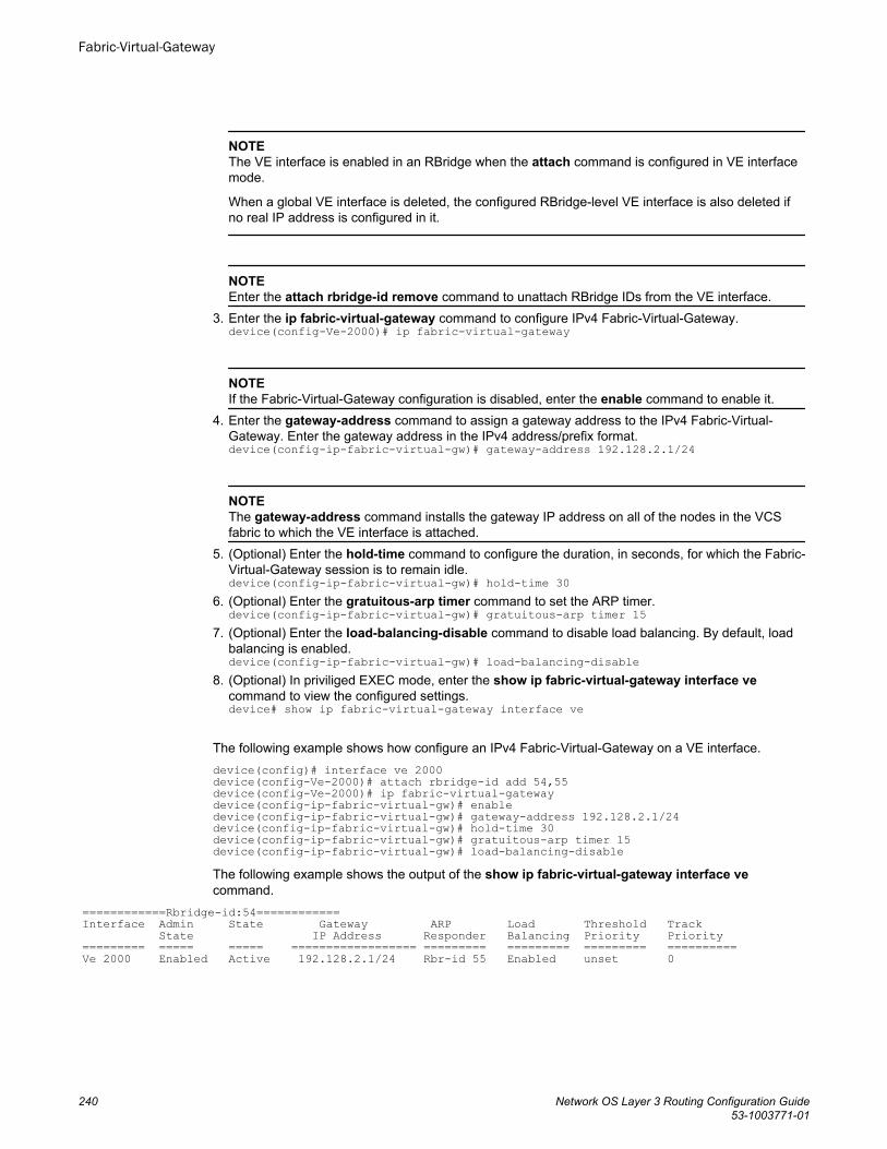
NOTEThe VE interface is enabled in an RBridge when the attach command is configured in VE interfacemode.
When a global VE interface is deleted, the configured RBridge-level VE interface is also deleted ifno real IP address is configured in it.
NOTEEnter the attach rbridge-id remove command to unattach RBridge IDs from the VE interface.
3. Enter the ip fabric-virtual-gateway command to configure IPv4 Fabric-Virtual-Gateway.device(config-Ve-2000)# ip fabric-virtual-gateway
NOTEIf the Fabric-Virtual-Gateway configuration is disabled, enter the enable command to enable it.
4. Enter the gateway-address command to assign a gateway address to the IPv4 Fabric-Virtual-Gateway. Enter the gateway address in the IPv4 address/prefix format.device(config-ip-fabric-virtual-gw)# gateway-address 192.128.2.1/24
NOTEThe gateway-address command installs the gateway IP address on all of the nodes in the VCSfabric to which the VE interface is attached.
5. (Optional) Enter the hold-time command to configure the duration, in seconds, for which the Fabric-Virtual-Gateway session is to remain idle.device(config-ip-fabric-virtual-gw)# hold-time 30
6. (Optional) Enter the gratuitous-arp timer command to set the ARP timer.device(config-ip-fabric-virtual-gw)# gratuitous-arp timer 15
7. (Optional) Enter the load-balancing-disable command to disable load balancing. By default, loadbalancing is enabled.device(config-ip-fabric-virtual-gw)# load-balancing-disable
8. (Optional) In priviliged EXEC mode, enter the show ip fabric-virtual-gateway interface vecommand to view the configured settings.device# show ip fabric-virtual-gateway interface ve
The following example shows how configure an IPv4 Fabric-Virtual-Gateway on a VE interface.device(config)# interface ve 2000device(config-Ve-2000)# attach rbridge-id add 54,55device(config-Ve-2000)# ip fabric-virtual-gatewaydevice(config-ip-fabric-virtual-gw)# enabledevice(config-ip-fabric-virtual-gw)# gateway-address 192.128.2.1/24device(config-ip-fabric-virtual-gw)# hold-time 30device(config-ip-fabric-virtual-gw)# gratuitous-arp timer 15device(config-ip-fabric-virtual-gw)# load-balancing-disableThe following example shows the output of the show ip fabric-virtual-gateway interface vecommand.
============Rbridge-id:54============Interface Admin State Gateway ARP Load Threshold Track State IP Address Responder Balancing Priority Priority========= ===== ===== ================== ========= ========= ========= ==========Ve 2000 Enabled Active 192.128.2.1/24 Rbr-id 55 Enabled unset 0
Fabric-Virtual-Gateway
240 Network OS Layer 3 Routing Configuration Guide53-1003771-01
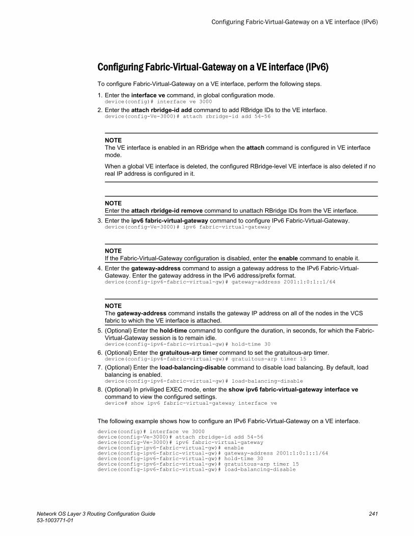
Configuring Fabric-Virtual-Gateway on a VE interface (IPv6)To configure Fabric-Virtual-Gateway on a VE interface, perform the following steps.
1. Enter the interface ve command, in global configuration mode.device(config)# interface ve 3000
2. Enter the attach rbridge-id add command to add RBridge IDs to the VE interface.device(config-Ve-3000)# attach rbridge-id add 54-56
NOTEThe VE interface is enabled in an RBridge when the attach command is configured in VE interfacemode.
When a global VE interface is deleted, the configured RBridge-level VE interface is also deleted if noreal IP address is configured in it.
NOTEEnter the attach rbridge-id remove command to unattach RBridge IDs from the VE interface.
3. Enter the ipv6 fabric-virtual-gateway command to configure IPv6 Fabric-Virtual-Gateway.device(config-Ve-3000)# ipv6 fabric-virtual-gateway
NOTEIf the Fabric-Virtual-Gateway configuration is disabled, enter the enable command to enable it.
4. Enter the gateway-address command to assign a gateway address to the IPv6 Fabric-Virtual-Gateway. Enter the gateway address in the IPv6 address/prefix format.device(config-ipv6-fabric-virtual-gw)# gateway-address 2001:1:0:1::1/64
NOTEThe gateway-address command installs the gateway IP address on all of the nodes in the VCSfabric to which the VE interface is attached.
5. (Optional) Enter the hold-time command to configure the duration, in seconds, for which the Fabric-Virtual-Gateway session is to remain idle.device(config-ipv6-fabric-virtual-gw)# hold-time 30
6. (Optional) Enter the gratuitous-arp timer command to set the gratuitous-arp timer.device(config-ipv6-fabric-virtual-gw)# gratuitous-arp timer 15
7. (Optional) Enter the load-balancing-disable command to disable load balancing. By default, loadbalancing is enabled.device(config-ipv6-fabric-virtual-gw)# load-balancing-disable
8. (Optional) In priviliged EXEC mode, enter the show ipv6 fabric-virtual-gateway interface vecommand to view the configured settings.device# show ipv6 fabric-virtual-gateway interface ve
The following example shows how to configure an IPv6 Fabric-Virtual-Gateway on a VE interface.device(config)# interface ve 3000device(config-Ve-3000)# attach rbridge-id add 54-56device(config-Ve-3000)# ipv6 fabric-virtual-gatewaydevice(config-ipv6-fabric-virtual-gw)# enabledevice(config-ipv6-fabric-virtual-gw)# gateway-address 2001:1:0:1::1/64device(config-ipv6-fabric-virtual-gw)# hold-time 30device(config-ipv6-fabric-virtual-gw)# gratuitous-arp timer 15device(config-ipv6-fabric-virtual-gw)# load-balancing-disable
Configuring Fabric-Virtual-Gateway on a VE interface (IPv6)
Network OS Layer 3 Routing Configuration Guide 24153-1003771-01
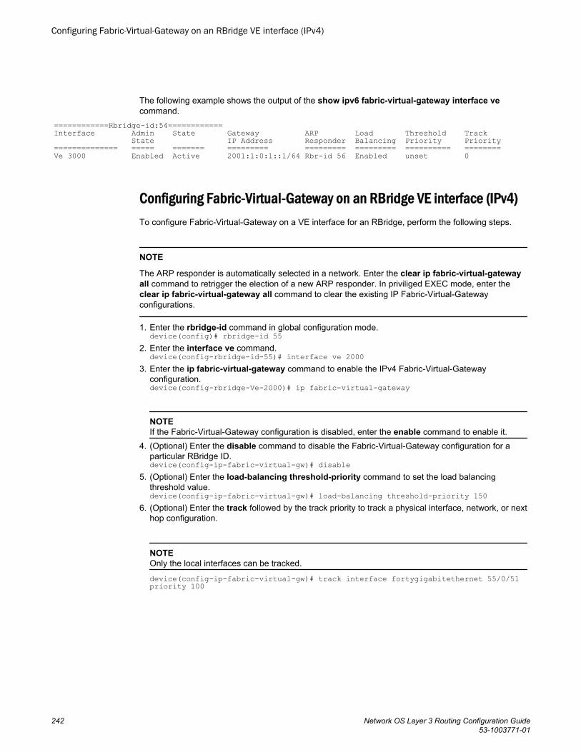
The following example shows the output of the show ipv6 fabric-virtual-gateway interface vecommand.
============Rbridge-id:54============Interface Admin State Gateway ARP Load Threshold Track State IP Address Responder Balancing Priority Priority============== ===== ======= ========= ========= ========= ========== ========Ve 3000 Enabled Active 2001:1:0:1::1/64 Rbr-id 56 Enabled unset 0
Configuring Fabric-Virtual-Gateway on an RBridge VE interface (IPv4)To configure Fabric-Virtual-Gateway on a VE interface for an RBridge, perform the following steps.
NOTE
The ARP responder is automatically selected in a network. Enter the clear ip fabric-virtual-gatewayall command to retrigger the election of a new ARP responder. In priviliged EXEC mode, enter theclear ip fabric-virtual-gateway all command to clear the existing IP Fabric-Virtual-Gatewayconfigurations.
1. Enter the rbridge-id command in global configuration mode.device(config)# rbridge-id 55
2. Enter the interface ve command.device(config-rbridge-id-55)# interface ve 2000
3. Enter the ip fabric-virtual-gateway command to enable the IPv4 Fabric-Virtual-Gatewayconfiguration.device(config-rbridge-Ve-2000)# ip fabric-virtual-gateway
NOTEIf the Fabric-Virtual-Gateway configuration is disabled, enter the enable command to enable it.
4. (Optional) Enter the disable command to disable the Fabric-Virtual-Gateway configuration for aparticular RBridge ID.device(config-ip-fabric-virtual-gw)# disable
5. (Optional) Enter the load-balancing threshold-priority command to set the load balancingthreshold value.device(config-ip-fabric-virtual-gw)# load-balancing threshold-priority 150
6. (Optional) Enter the track followed by the track priority to track a physical interface, network, or nexthop configuration.
NOTEOnly the local interfaces can be tracked.
device(config-ip-fabric-virtual-gw)# track interface fortygigabitethernet 55/0/51 priority 100
Configuring Fabric-Virtual-Gateway on an RBridge VE interface (IPv4)
242 Network OS Layer 3 Routing Configuration Guide53-1003771-01
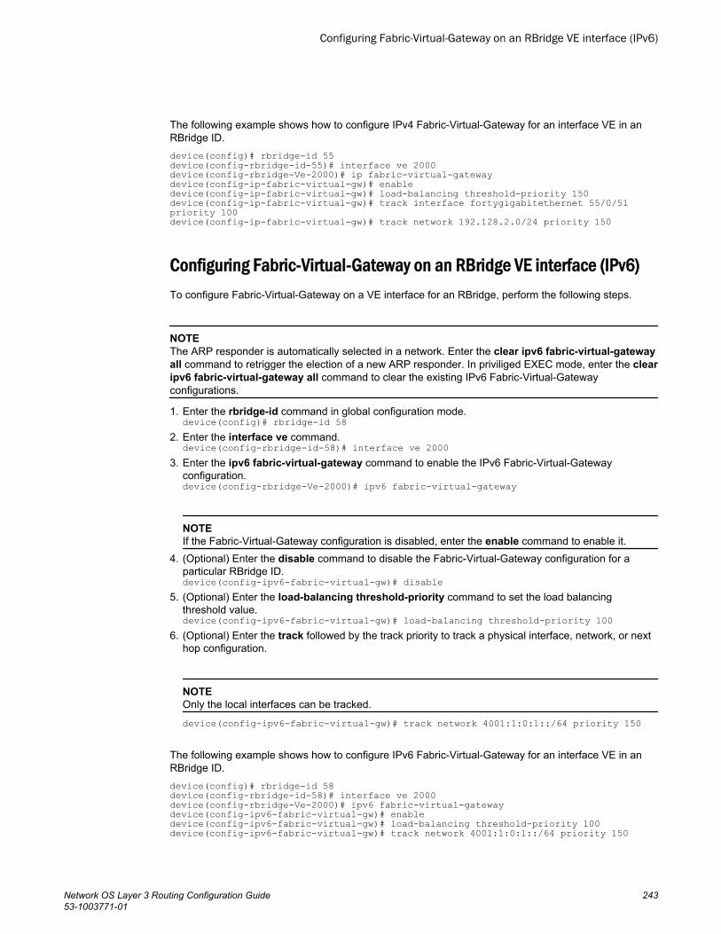
The following example shows how to configure IPv4 Fabric-Virtual-Gateway for an interface VE in anRBridge ID.device(config)# rbridge-id 55device(config-rbridge-id-55)# interface ve 2000device(config-rbridge-Ve-2000)# ip fabric-virtual-gatewaydevice(config-ip-fabric-virtual-gw)# enabledevice(config-ip-fabric-virtual-gw)# load-balancing threshold-priority 150device(config-ip-fabric-virtual-gw)# track interface fortygigabitethernet 55/0/51 priority 100device(config-ip-fabric-virtual-gw)# track network 192.128.2.0/24 priority 150
Configuring Fabric-Virtual-Gateway on an RBridge VE interface (IPv6)To configure Fabric-Virtual-Gateway on a VE interface for an RBridge, perform the following steps.
NOTEThe ARP responder is automatically selected in a network. Enter the clear ipv6 fabric-virtual-gatewayall command to retrigger the election of a new ARP responder. In priviliged EXEC mode, enter the clearipv6 fabric-virtual-gateway all command to clear the existing IPv6 Fabric-Virtual-Gatewayconfigurations.
1. Enter the rbridge-id command in global configuration mode.device(config)# rbridge-id 58
2. Enter the interface ve command.device(config-rbridge-id-58)# interface ve 2000
3. Enter the ipv6 fabric-virtual-gateway command to enable the IPv6 Fabric-Virtual-Gatewayconfiguration.device(config-rbridge-Ve-2000)# ipv6 fabric-virtual-gateway
NOTEIf the Fabric-Virtual-Gateway configuration is disabled, enter the enable command to enable it.
4. (Optional) Enter the disable command to disable the Fabric-Virtual-Gateway configuration for aparticular RBridge ID.device(config-ipv6-fabric-virtual-gw)# disable
5. (Optional) Enter the load-balancing threshold-priority command to set the load balancingthreshold value.device(config-ipv6-fabric-virtual-gw)# load-balancing threshold-priority 100
6. (Optional) Enter the track followed by the track priority to track a physical interface, network, or nexthop configuration.
NOTEOnly the local interfaces can be tracked.
device(config-ipv6-fabric-virtual-gw)# track network 4001:1:0:1::/64 priority 150
The following example shows how to configure IPv6 Fabric-Virtual-Gateway for an interface VE in anRBridge ID.device(config)# rbridge-id 58device(config-rbridge-id-58)# interface ve 2000device(config-rbridge-Ve-2000)# ipv6 fabric-virtual-gatewaydevice(config-ipv6-fabric-virtual-gw)# enabledevice(config-ipv6-fabric-virtual-gw)# load-balancing threshold-priority 100device(config-ipv6-fabric-virtual-gw)# track network 4001:1:0:1::/64 priority 150
Configuring Fabric-Virtual-Gateway on an RBridge VE interface (IPv6)
Network OS Layer 3 Routing Configuration Guide 24353-1003771-01
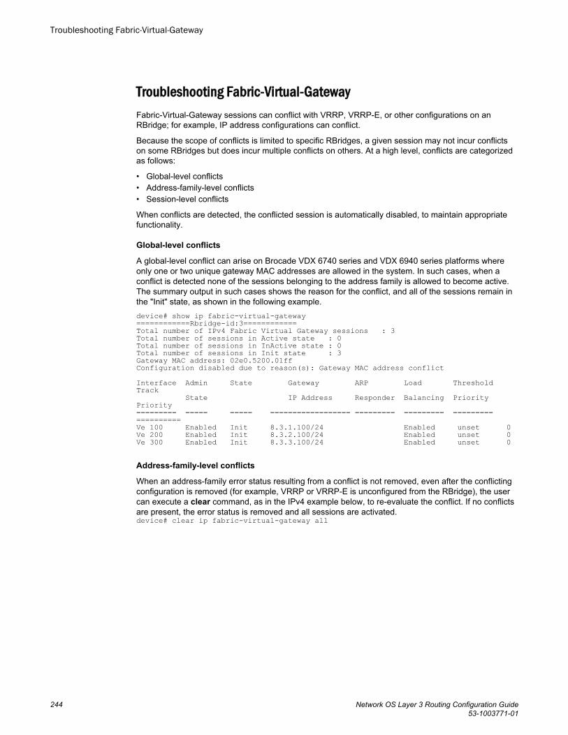
Troubleshooting Fabric-Virtual-GatewayFabric-Virtual-Gateway sessions can conflict with VRRP, VRRP-E, or other configurations on anRBridge; for example, IP address configurations can conflict.
Because the scope of conflicts is limited to specific RBridges, a given session may not incur conflictson some RBridges but does incur multiple conflicts on others. At a high level, conflicts are categorizedas follows:
• Global-level conflicts• Address-family-level conflicts• Session-level conflicts
When conflicts are detected, the conflicted session is automatically disabled, to maintain appropriatefunctionality.
Global-level conflicts
A global-level conflict can arise on Brocade VDX 6740 series and VDX 6940 series platforms whereonly one or two unique gateway MAC addresses are allowed in the system. In such cases, when aconflict is detected none of the sessions belonging to the address family is allowed to become active.The summary output in such cases shows the reason for the conflict, and all of the sessions remain inthe "Init" state, as shown in the following example.device# show ip fabric-virtual-gateway============Rbridge-id:3============Total number of IPv4 Fabric Virtual Gateway sessions : 3Total number of sessions in Active state : 0Total number of sessions in InActive state : 0Total number of sessions in Init state : 3Gateway MAC address: 02e0.5200.01ffConfiguration disabled due to reason(s): Gateway MAC address conflictInterface Admin State Gateway ARP Load Threshold Track State IP Address Responder Balancing Priority Priority========= ===== ===== ================== ========= ========= ========= ==========Ve 100 Enabled Init 8.3.1.100/24 Enabled unset 0Ve 200 Enabled Init 8.3.2.100/24 Enabled unset 0Ve 300 Enabled Init 8.3.3.100/24 Enabled unset 0
Address-family-level conflicts
When an address-family error status resulting from a conflict is not removed, even after the conflictingconfiguration is removed (for example, VRRP or VRRP-E is unconfigured from the RBridge), the usercan execute a clear command, as in the IPv4 example below, to re-evaluate the conflict. If no conflictsare present, the error status is removed and all sessions are activated.device# clear ip fabric-virtual-gateway all
Troubleshooting Fabric-Virtual-Gateway
244 Network OS Layer 3 Routing Configuration Guide53-1003771-01
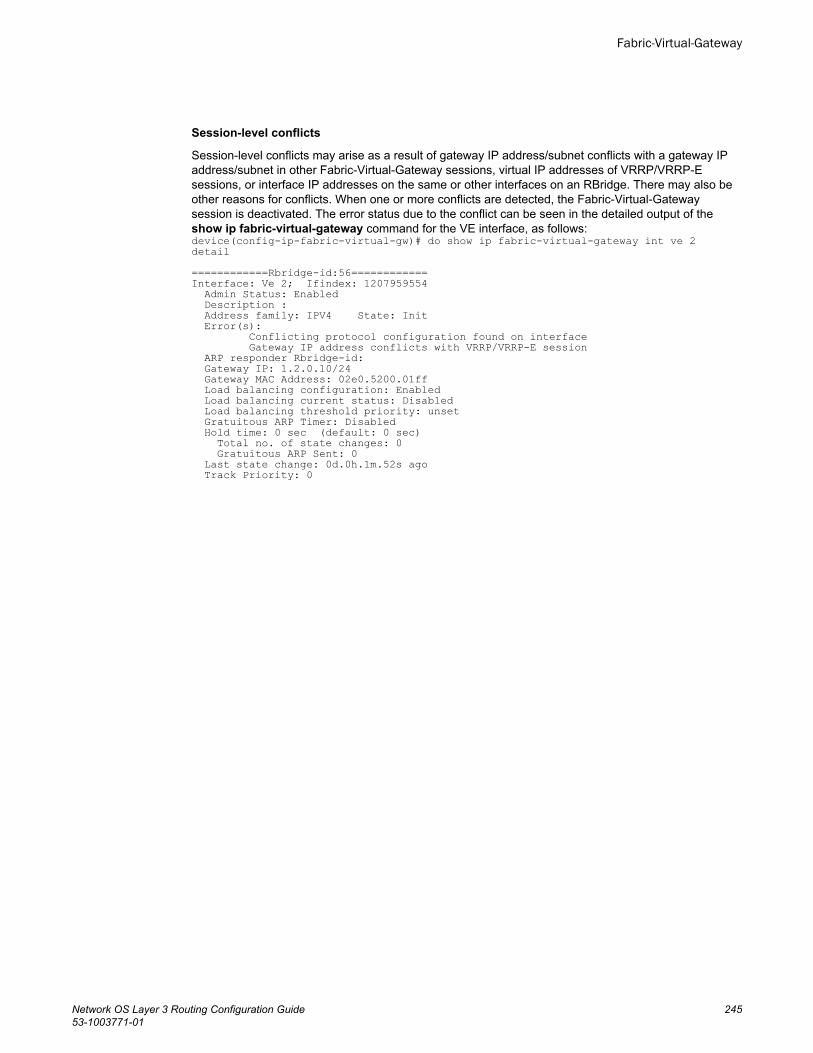
Session-level conflicts
Session-level conflicts may arise as a result of gateway IP address/subnet conflicts with a gateway IPaddress/subnet in other Fabric-Virtual-Gateway sessions, virtual IP addresses of VRRP/VRRP-Esessions, or interface IP addresses on the same or other interfaces on an RBridge. There may also beother reasons for conflicts. When one or more conflicts are detected, the Fabric-Virtual-Gatewaysession is deactivated. The error status due to the conflict can be seen in the detailed output of theshow ip fabric-virtual-gateway command for the VE interface, as follows:device(config-ip-fabric-virtual-gw)# do show ip fabric-virtual-gateway int ve 2 detail ============Rbridge-id:56============Interface: Ve 2; Ifindex: 1207959554 Admin Status: Enabled Description : Address family: IPV4 State: Init Error(s): Conflicting protocol configuration found on interface Gateway IP address conflicts with VRRP/VRRP-E session ARP responder Rbridge-id: Gateway IP: 1.2.0.10/24 Gateway MAC Address: 02e0.5200.01ff Load balancing configuration: Enabled Load balancing current status: Disabled Load balancing threshold priority: unset Gratuitous ARP Timer: Disabled Hold time: 0 sec (default: 0 sec) Total no. of state changes: 0 Gratuitous ARP Sent: 0 Last state change: 0d.0h.1m.52s ago Track Priority: 0
Fabric-Virtual-Gateway
Network OS Layer 3 Routing Configuration Guide 24553-1003771-01

Troubleshooting Fabric-Virtual-Gateway
246 Network OS Layer 3 Routing Configuration Guide53-1003771-01
Virtual Routing and Forwarding
● VRF overview................................................................................................................247● Configuring VRF ...........................................................................................................248● Inter-VRF route leaking................................................................................................. 250● Understanding and using management services in default-vrf and mgmt-vrf............... 257
VRF overviewVRF (Virtual Routing and Forwarding) is a technology that controls information flow within a network byisolating the traffic by partitioning the network into different logical VRF domains. This allows a singlerouter or switch to have multiple containers of routing tables or Forwarding Information Bases (FIB)inside it, with one routing table for each VRF instance. This permits a VRF-capable router to function asa group of multiple virtual routers on the same physical router. VRF, in conjunction with virtual privatenetwork (VPN) solutions, guarantees privacy of information and isolation of traffic within a logical VRFdomain.
A typical implementation of a Virtual Routing and Forwarding instance (referred to as a VRF) aredesigned to support Border Gateway Protocol (BGP) or Multiprotocol Label Switching (MPLS) VPNs,whereas implementations of VRF-Lite (also referred to as Multi-VRF) typically are much simpler withreduced scalability. The two VRF flavors have a lot in common but differ in the interconnect schemes,routing protocols used over the interconnect, and also in VRF classification mechanisms.
VRF is supported on the Brocade VDX 8770 and VDX 6740 series platforms. The VDX 8770 supports128 VRF instances and the VDX 6740 supports 32 VRF instances per physical switch.
Brocade Network OS 4.0.0 and later supports the VRF-Lite implementation. Unless otherwise noted, allreferences to VRF in this document also apply to VRF-Lite.
VRF topologyThis diagram illustrates a typical VRF topology with a single VCS comprising Customer 1 Edge,Provider Edge, and Customer 2 Edge routers.
The orange and green ovals indicate two VPNs supporting two different customer sites. Both of themhave overlapping IP subnets; 100.100.100.0/24 and 100.100.200.0/24.
Network OS Layer 3 Routing Configuration Guide 24753-1003771-01
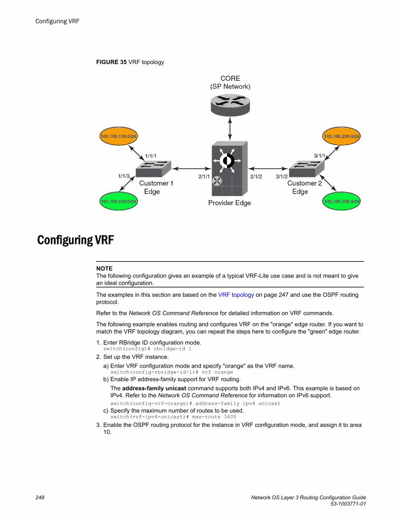
FIGURE 35 VRF topology
Configuring VRF
NOTEThe following configuration gives an example of a typical VRF-Lite use case and is not meant to givean ideal configuration.
The examples in this section are based on the VRF topology on page 247 and use the OSPF routingprotocol.
Refer to the Network OS Command Reference for detailed information on VRF commands.
The following example enables routing and configures VRF on the "orange" edge router. If you want tomatch the VRF topology diagram, you can repeat the steps here to configure the "green" edge router.
1. Enter RBridge ID configuration mode.switch(config)# rbridge-id 1
2. Set up the VRF instance.a) Enter VRF configuration mode and specify "orange" as the VRF name.
switch(config-rbridge-id-1)# vrf orangeb) Enable IP address-family support for VRF routing.
The address-family unicast command supports both IPv4 and IPv6. This example is based onIPv4. Refer to the Network OS Command Reference for information on IPv6 support.switch(config-vrf-orange)# address-family ipv4 unicast
c) Specify the maximum number of routes to be used.switch(vrf-ipv4-unicast)# max-route 3600
3. Enable the OSPF routing protocol for the instance in VRF configuration mode, and assign it to area10.
Configuring VRF
248 Network OS Layer 3 Routing Configuration Guide53-1003771-01
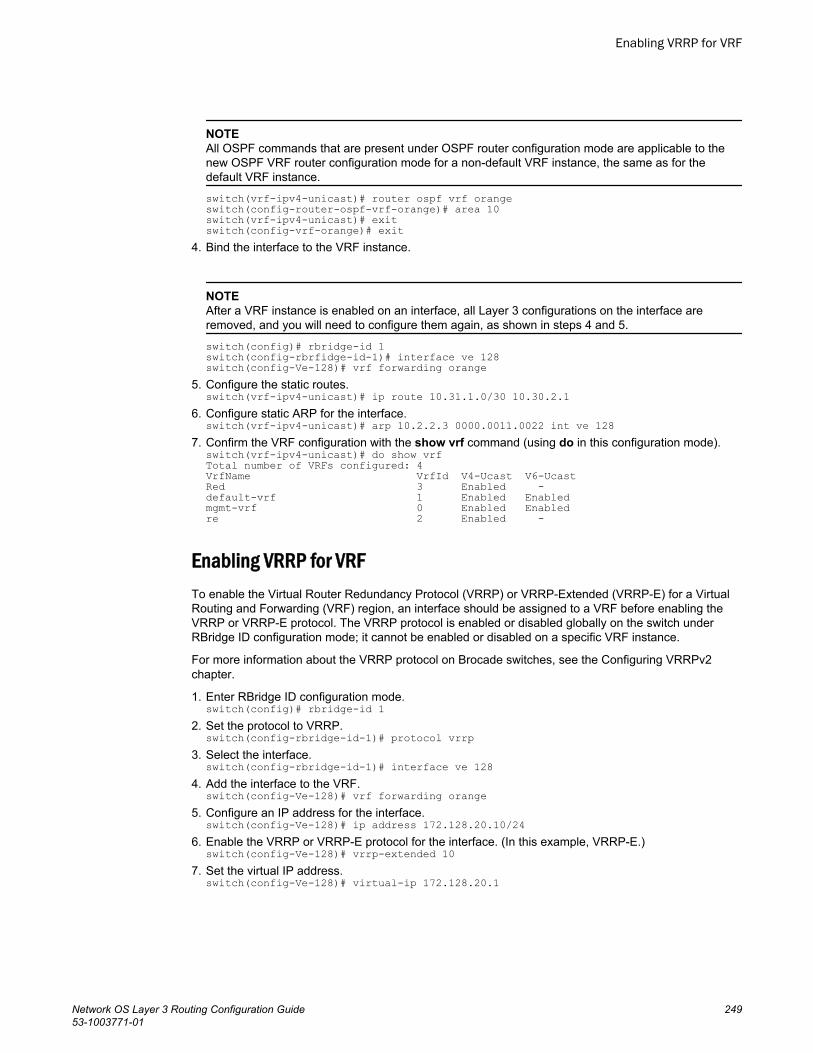
NOTEAll OSPF commands that are present under OSPF router configuration mode are applicable to thenew OSPF VRF router configuration mode for a non-default VRF instance, the same as for thedefault VRF instance.
switch(vrf-ipv4-unicast)# router ospf vrf orangeswitch(config-router-ospf-vrf-orange)# area 10switch(vrf-ipv4-unicast)# exitswitch(config-vrf-orange)# exit
4. Bind the interface to the VRF instance.
NOTEAfter a VRF instance is enabled on an interface, all Layer 3 configurations on the interface areremoved, and you will need to configure them again, as shown in steps 4 and 5.
switch(config)# rbridge-id 1switch(config-rbrfidge-id-1)# interface ve 128switch(config-Ve-128)# vrf forwarding orange
5. Configure the static routes.switch(vrf-ipv4-unicast)# ip route 10.31.1.0/30 10.30.2.1
6. Configure static ARP for the interface.switch(vrf-ipv4-unicast)# arp 10.2.2.3 0000.0011.0022 int ve 128
7. Confirm the VRF configuration with the show vrf command (using do in this configuration mode).switch(vrf-ipv4-unicast)# do show vrfTotal number of VRFs configured: 4VrfName VrfId V4-Ucast V6-UcastRed 3 Enabled -default-vrf 1 Enabled Enabledmgmt-vrf 0 Enabled Enabledre 2 Enabled -
Enabling VRRP for VRFTo enable the Virtual Router Redundancy Protocol (VRRP) or VRRP-Extended (VRRP-E) for a VirtualRouting and Forwarding (VRF) region, an interface should be assigned to a VRF before enabling theVRRP or VRRP-E protocol. The VRRP protocol is enabled or disabled globally on the switch underRBridge ID configuration mode; it cannot be enabled or disabled on a specific VRF instance.
For more information about the VRRP protocol on Brocade switches, see the Configuring VRRPv2chapter.
1. Enter RBridge ID configuration mode.switch(config)# rbridge-id 1
2. Set the protocol to VRRP.switch(config-rbridge-id-1)# protocol vrrp
3. Select the interface.switch(config-rbridge-id-1)# interface ve 128
4. Add the interface to the VRF.switch(config-Ve-128)# vrf forwarding orange
5. Configure an IP address for the interface.switch(config-Ve-128)# ip address 172.128.20.10/24
6. Enable the VRRP or VRRP-E protocol for the interface. (In this example, VRRP-E.)switch(config-Ve-128)# vrrp-extended 10
7. Set the virtual IP address.switch(config-Ve-128)# virtual-ip 172.128.20.1
Enabling VRRP for VRF
Network OS Layer 3 Routing Configuration Guide 24953-1003771-01
Inter-VRF route leakingVirtual Routing and Forwarding (VRF) is a technology that provides you with the ability to havemultiple virtual routers on a single physical router or switch. VRFs operate without knowledge of oneanother unless they are imported or exported into one another using Inter-VRF Route Leaking. Inter-VRF route leaking allows leaking of route prefixes from one VRF instance to another VRF instance onthe same physical router, which eliminates the need for external routing. This is useful in cases wheremultiple VRFs share the same path to reach an external domain, while maintaining their internalrouting information limited to their own VRF. This feature enables a data center to consolidate multipleVRF services onto a single server.
Both static and dynamic route leaking are supported. Each routed interface (whether virtual orphysical) can belong to only one VRF.
Static route leaking provides a mechanism to leak manually configured route entries from a sourceVRF to a destination VRF.
Dynamic route leaking provides a mechanism to leak routes learned from routing protocols such asBGP and OSPF from a source VRF to a destination VRF. Routes can be leaked by configuring a routemap and associating this route map with a source VRF. The match criteria defined in the route mapconsists of specific route prefixes that exist in the source VRF.
For more information on VRF functionality, refer to VRF overview on page 247.
Dynamic route leak restrictions• Exporting of route maps is not supported.• Match criteria in a route map must be provided with prefix lists; other match criteria is ignored.• Connected routes are not leaked.• Routes in management-vrf with next-hop as eth0 or management interface are not leaked.
Inter-VRF route conflictsVRF Route Leaking is a feature which should only be deployed by an advanced user, as route leakconfiguration in source VRFs may collide with route/interface definitions in target VRFs. This may leadto unpredictable behavior in packet forwarding.
Some of the ways that leaked route conflicts can occur are the following:
• Static route conflict• Dynamic route conflict• Connected route conflict
A static route conflict may happen when the same prefix is reachable by two different next hops in thetarget VRF. The forwarding behavior would be different based on which command occurred later. Thisfollowing example presents a static route conflict for 10.1.2.0/24.switch(config)# vrf redswitch(config)# ip route 10.1.2.0/24 next-hop-vrf green 10.1.1.1switch(config)# vrf greenswitch(config)# ip route 10.1.2.0/24 18.1.1.1
NOTEHowever, if the source of the prefix in each case is different (for example, 10.1.2.0 comes from OSPF,BGP, static, or connected, then the method of conflict resolution mentioned above (where the mostrecent configuration takes precedence) does not apply. The order of preference is as follows: (1)connected, (2) static, (3) OSPF, (4) BGP, assuming that the administrative distances for the prefixes
Inter-VRF route leaking
250 Network OS Layer 3 Routing Configuration Guide53-1003771-01
are the defaults. In other words, when the prefix is installed through different sources (OSPF/BGP/static/connected), the prefix with the lowest administrative distance takes precedence. The mostrecently configured prefix rule applies only if the source of the prefix is the same.
ATTENTIONEnsure that identical prefixes are not leaked.
A dynamic route conflict can occur when dynamic routing protocols advertise different routes to thesame prefix in the target VRF.
A connected route conflict is illustrated by the following example:switch(config)# vrf redswitch(config)# ip route 10.1.2.0/24 next-hop-vrf green 10.1.1.1switch(config)# interface Te 1/2/1switch(config)# vrf forwarding greenswitch(config)# ip address 10.1.2.1/24
NOTEThe user must be aware of such possible conflicts before deploying the route leak feature, as currentlythere is no error checking for these scenarios. A good rule is to make sure that definitions are globallyunique and route collisions do not exist.
Displaying Inter-VRF route leakingThe show command for the IP routing table (show ip route) displays a ‘+’ sign next to the route type forthe leaked routes in a VRF.
The following example shows the static route using the next-hop VRF option for route leaking:switch# show ip routeTotal number of IP routes: 3Type Codes - B:BGP D:Connected I:ISIS O:OSPF R:RIP S:Static; Cost - Dist/MetricBGP Codes - i:iBGP e:eBGPISIS Codes - L1:Level-1 L2:Level-2OSPF Codes - i:Inter Area 1:External Type 1 2:External Type 2 s:Sham Link Destination Gateway Port Cost Type Uptime1 0.0.0.0/0 10.24.64.1 mgmt 1 1/1 S 8m24s2 1.1.1.0/24 10.1.1.10 Ve 10 1/1 S+ 3m11s 3 10.24.64.0/20 DIRECT mgmt 1 0/0 D 8m28s Notice the '+' sign next to the Type entry for route entry 2.
You can also determine the leaked route for a specific VRF, as part of the (show ip route) command,as illustrated in the following example:switch# show ip route vrf vrf1Total number of IP routes: 2Type Codes - B:BGP D:Connected I:ISIS O:OSPF R:RIP S:Static; Cost - Dist/MetricBGP Codes - i:iBGP e:eBGPISIS Codes - L1:Level-1 L2:Level-2OSPF Codes - i:Inter Area 1:External Type 1 2:External Type 2 s:Sham Link Destination Gateway Port Cost Type Uptime1 0.0.0.0/0 192.168.64.1 mgmt 1 1/1 S 8m24s2 10.11.11.0/24 192.168.21.2 Ve 12 1/1 S+ 3m11s Notice the '+' sign next to the Type entry for route entry 2.
Virtual Routing and Forwarding
Network OS Layer 3 Routing Configuration Guide 25153-1003771-01
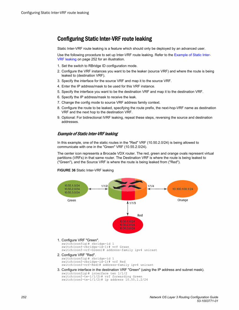
Configuring Static Inter-VRF route leakingStatic Inter-VRF route leaking is a feature which should only be deployed by an advanced user.
Use the following procedure to set up Inter-VRF route leaking. Refer to the Example of Static Inter-VRF leaking on page 252 for an illustration.
1. Set the switch to RBridge ID configuration mode.2. Configure the VRF instances you want to be the leaker (source VRF) and where the route is being
leaked to (destination VRF).3. Specify the interface for the source VRF and map it to the source VRF.4. Enter the IP address/mask to be used for this VRF instance.5. Specify the interface you want to be the destination VRF and map it to the destination VRF.6. Specify the IP address/mask to receive the leak.7. Change the config mode to source VRF address family context.8. Configure the route to be leaked, specifying the route prefix, the next-hop-VRF name as destination
VRF and the next hop to the destination VRF.9. Optional: For bidirectional IVRF leaking, repeat these steps, reversing the source and destination
addresses.
Example of Static Inter-VRF leaking
In this example, one of the static routes in the "Red" VRF (10.50.2.0/24) is being allowed tocommunicate with one in the "Green" VRF (10.55.2.0/24).
The center icon represents a Brocade VDX router. The red, green and orange ovals represent virtualpartitions (VRFs) in that same router. The Destination VRF is where the route is being leaked to("Green"), and the Source VRF is where the route is being leaked from ("Red").
FIGURE 36 Static Inter-VRF leaking
1. Configure VRF "Green".switch(config)# rbridge-id 1switch(conf-rbridge-id-1)# vrf Greenswitch(conf-vrf-Green)# address-family ipv4 unicast
2. Configure VRF "Red".switch(config)# rbridge-id 1switch(conf-rbridge-id-1)# vrf Redswitch(conf-vrf-Red)# address-family ipv4 unicast
3. Configure interface in the destination VRF "Green" (using the IP address and subnet mask).switch(config)# interface ten 1/1/2switch(conf-te-1/1/2)# vrf forwarding Greenswitch(conf-te-1/1/2)# ip address 10.55.1.2/24
Configuring Static Inter-VRF route leaking
252 Network OS Layer 3 Routing Configuration Guide53-1003771-01
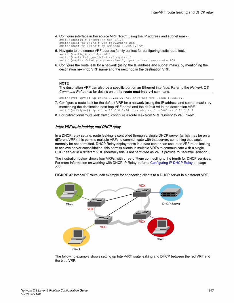
4. Configure interface in the source VRF "Red" (using the IP address and subnet mask).switch(config)# interface ten 1/1/3switch(conf-te-1/1/3)# vrf forwarding Redswitch(conf-te-1/1/3)# ip address 10.50.1.2/24
5. Navigate to the source VRF address family context for configuring static route leak.switch(config)# rbridge-id 1switch(conf-rbridge-id-1)# vrf mgmt-vrfswitch(conf-vrf-Red)# address-family ipv4 unicast max-route 400
6. Configure the route leak for a network (using the IP address and subnet mask), by mentioning thedestination next-hop VRF name and the next hop in the destination VRF.
NOTEThe destination VRF can also be a specific port on an Ethernet interface. Refer to the Network OSCommand Reference for details on the ip route next-hop-vrf command.
switch(vrf-ipv4)# ip route 10.55.2.0/24 next-hop-vrf Green 10.55.1.17. Configure a route leak for the default VRF for a network (using the IP address and subnet mask), by
mentioning the destination next-hop VRF name and the default-vrf in the destination VRF.switch(vrf-ipv4)# ip route 20.0.0.0/24 next-hop-vrf default-vrf 10.1.1.1
8. For bidirectional route leak traffic, configure a route leak from VRF "Green" to VRF "Red".
Inter-VRF route leaking and DHCP relay
In a DHCP relay setting, route leaking is controlled through a single DHCP server (which may be on adifferent VRF); this permits multiple VRFs to communicate with that server, something that wouldnormally be not permitted. DHCP Relay deployments in a data center can use Inter-VRF route leakingto achieve server consolidation; this permits clients in multiple VRFs to communicate with a singleDHCP server in a different VRF (normally this is not permitted as VRFs provide route/traffic isolation).
The illustration below shows four VRFs, with three of them connecting to the fourth for DHCP services.For more information on working with DHCP IP Relay, refer to Configuring IP DHCP Relay on page277.
FIGURE 37 Inter-VRF route leak example for connecting clients to a DHCP server in a different VRF.
The following example shows setting up Inter-VRF route leaking and DHCP between the red VRF andthe blue VRF.
Inter-VRF route leaking and DHCP relay
Network OS Layer 3 Routing Configuration Guide 25353-1003771-01
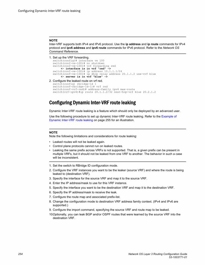
NOTEInter-VRF supports both IPv4 and IPv6 protocol. Use the ip address and ip route commands for IPv4protocol and ipv6 address and ipv6 route commands for IPv6 protocol. Refer to the Network OSCommand Reference.
1. Set up the VRF forwarding.switch(config)# interface ve 100switch(conf-ve-100)# no shutdownswitch(conf-ve-100)# vrf forwarding red <- interface is in vrf "red" ->switch(conf-ve-100)# ip address 10.1.1.1/24switch(conf-ve-100)# ip dhcp relay address 20.1.1.2 use-vrf blue <- server is in vrf "blue" ->
2. Configure the leaked route on vrf red.switch(config) rbridge-id 1switch(conf-rbridge-id-1)# vrf redswitch(conf-vrf-red)# address-family ipv4 max-routeswitch(vrf-ipv4)#ip route 20.1.1.2/32 next-hop-vrf blue 20.2.1.2
Configuring Dynamic Inter-VRF route leakingDynamic Inter-VRF route leaking is a feature which should only be deployed by an advanced user.
Use the following procedure to set up dynamic Inter-VRF route leaking. Refer to the Example ofDynamic Inter-VRF route leaking on page 255 for an illustration.
NOTENote the following limitations and considerations for route leaking:
• Leaked routes will not be leaked again.• Control plane protocols cannot run on leaked routes.• Leaking the same prefix across VRFs is not supported. That is, a given prefix can be present in
multiple VRFs, but it should not be leaked from one VRF to another. The behavior in such a casewill be inconsistent.
1. Set the switch to RBridge ID configuration mode.2. Configure the VRF instances you want to be the leaker (source VRF) and where the route is being
leaked to (destination VRF).3. Specify the interface for the source VRF and map it to the source VRF.4. Enter the IP address/mask to use for this VRF instance.5. Specify the interface you want to be the destination VRF and map it to the destination VRF.6. Specify the IP address/mask to receive the leak.7. Configure the route map and associated prefix-list.8. Change the configuration mode to destination VRF address family context. (IPv4 and IPv6 are
supported.)9. Configure the import command, specifying the source VRF and route map to be leaked.10.Optionally, you can leak BGP and/or OSPF routes that were learned by the source VRF into the
destination VRF.
Configuring Dynamic Inter-VRF route leaking
254 Network OS Layer 3 Routing Configuration Guide53-1003771-01
Example of Dynamic Inter-VRF route leaking
In this example, a route map called "import-map" has match criteria specified as prefixes that can belearned by means of routing protocols such as OSPF or BGP.
The figure below depicts a typical dynamic route leak scenario. VRFs “Yellow” and “Green” are virtualpartitions in the same router. The Destination VRF is where the route is being leaked to ("Green"), andthe Source VRF is where the route is being leaked from ("Yellow"). In this example, IPv4 is used.
FIGURE 38 Dynamic Inter-VRF route leaking
1. Configure VRF "Green".switch(config)# rbridge-id 1switch(conf-rbridge-id-1)# vrf Greenswitch(conf-vrf-Green)# address-family ipv4 unicast
2. Configure VRF "Yellow".switch(config)# rbridge-id 1switch(conf-rbridge-id-1)# vrf Yellowswitch(conf-vrf-Yellow)# address-family ipv4 unicast
3. Configure an IPv4 prefix list, named "import-prefix" in this example.switch(config)# rbridge-id 1switch(config-rbridge-id-1)# ip prefix-list import-prefix permit 10.2.3.0/24switch(config-rbridge-id-1)# ip prefix-list import-prefix permit 10.1.2.0/24
4. Configure a route map with "match" conditions.switch(config-rbridge-id-1)# route-map import-map permit 10 switch(config-route-map-import-map/permit/10)# match ip address prefix-list import-prefix
5. Import the desired route map for the specified VRF.switch(config)# rbridge-id 1switch(conf-rbridge-id-1)# vrf Green
Example of Dynamic Inter-VRF route leaking
Network OS Layer 3 Routing Configuration Guide 25553-1003771-01
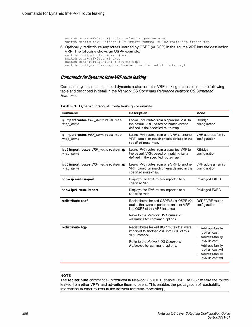
switch(conf-vrf-Green)# address-family ipv4 unicastswitch(config-ipv4-unicast)# ip import routes Yellow route-map import-map
6. Optionally, redistribute any routes learned by OSPF (or BGP) in the source VRF into the destinationVRF. The following shows an OSPF example.switch(config-ipv4-unicast)# exitswitch(conf-vrf-Green)# exitswitch(conf-rbridge-id-1)# router ospfswitch(config-router-ospf-vrf-default-vrf)# redistribute ospf
Commands for Dynamic Inter-VRF route leaking
Commands you can use to import dynamic routes for Inter-VRF leaking are included in the followingtable and described in detail in the Network OS Command Reference Network OS CommandReference.
Dynamic Inter-VRF route leaking commandsTABLE 3
Command Description Mode
ip import routes VRF_name route-maprmap_name
Leaks IPv4 routes from a specified VRF tothe default VRF, based on match criteriadefined in the specified route-map.
RBridgeconfiguration
ip import routes VRF_name route-maprmap_name
Leaks IPv4 routes from one VRF to anotherVRF, based on match criteria defined in thespecified route-map.
VRF address familyconfiguration
ipv6 import routes VRF_name route-maprmap_name
Leaks IPv6 routes from a specified VRF tothe default VRF, based on match criteriadefined in the specified route-map.
RBridgeconfiguration
ipv6 import routes VRF_name route-maprmap_name
Leaks IPv6 routes from one VRF to anotherVRF, based on match criteria defined in thespecified route-map.
VRF address familyconfiguration
show ip route import Displays the IPv4 routes imported to aspecified VRF.
Privileged EXEC
show ipv6 route import Displays the IPv6 routes imported to aspecified VRF.
Privileged EXEC
redistribute ospf Redistributes leaked OSPFv3 (or OSPF v2)routes that were imported to another VRFinto OSPF of this VRF instance.
Refer to the Network OS CommandReference for command options.
OSPF VRF routerconfiguration
redistribute bgp Redistributes leaked BGP routes that wereimported to another VRF into BGP of thisVRF instance.
Refer to the Network OS CommandReference for command options.
• Address-familyipv4 unicast
• Address-familyipv6 unicast
• Address-familyipv4 unicast vrf
• Address-familyipv6 unicast vrf
NOTEThe redistribute commands (introduced in Network OS 6.0.1) enable OSPF or BGP to take the routesleaked from other VRFs and advertise them to peers. This enables the propagation of reachabilityinformation to other routers in the network for traffic forwarding.)
Commands for Dynamic Inter-VRF route leaking
256 Network OS Layer 3 Routing Configuration Guide53-1003771-01
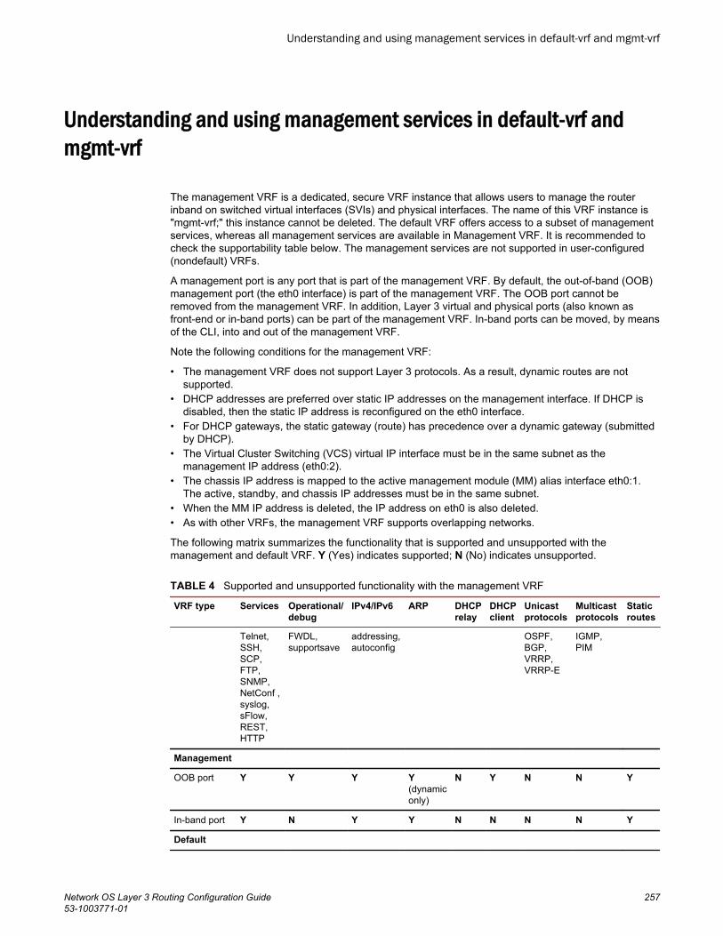
Understanding and using management services in default-vrf andmgmt-vrf
The management VRF is a dedicated, secure VRF instance that allows users to manage the routerinband on switched virtual interfaces (SVIs) and physical interfaces. The name of this VRF instance is"mgmt-vrf;" this instance cannot be deleted. The default VRF offers access to a subset of managementservices, whereas all management services are available in Management VRF. It is recommended tocheck the supportability table below. The management services are not supported in user-configured(nondefault) VRFs.
A management port is any port that is part of the management VRF. By default, the out-of-band (OOB)management port (the eth0 interface) is part of the management VRF. The OOB port cannot beremoved from the management VRF. In addition, Layer 3 virtual and physical ports (also known asfront-end or in-band ports) can be part of the management VRF. In-band ports can be moved, by meansof the CLI, into and out of the management VRF.
Note the following conditions for the management VRF:
• The management VRF does not support Layer 3 protocols. As a result, dynamic routes are notsupported.
• DHCP addresses are preferred over static IP addresses on the management interface. If DHCP isdisabled, then the static IP address is reconfigured on the eth0 interface.
• For DHCP gateways, the static gateway (route) has precedence over a dynamic gateway (submittedby DHCP).
• The Virtual Cluster Switching (VCS) virtual IP interface must be in the same subnet as themanagement IP address (eth0:2).
• The chassis IP address is mapped to the active management module (MM) alias interface eth0:1.The active, standby, and chassis IP addresses must be in the same subnet.
• When the MM IP address is deleted, the IP address on eth0 is also deleted.• As with other VRFs, the management VRF supports overlapping networks.
The following matrix summarizes the functionality that is supported and unsupported with themanagement and default VRF. Y (Yes) indicates supported; N (No) indicates unsupported.
Supported and unsupported functionality with the management VRFTABLE 4
VRF type Services Operational/debug
IPv4/IPv6 ARP DHCPrelay
DHCPclient
Unicastprotocols
Multicastprotocols
Staticroutes
Telnet,SSH,SCP,FTP,SNMP,NetConf ,syslog,sFlow,REST,HTTP
FWDL,supportsave
addressing,autoconfig
OSPF,BGP,VRRP,VRRP-E
IGMP,PIM
Management
OOB port Y Y Y Y(dynamiconly)
N Y N N Y
In-band port Y N Y Y N N N N Y
Default
Understanding and using management services in default-vrf and mgmt-vrf
Network OS Layer 3 Routing Configuration Guide 25753-1003771-01
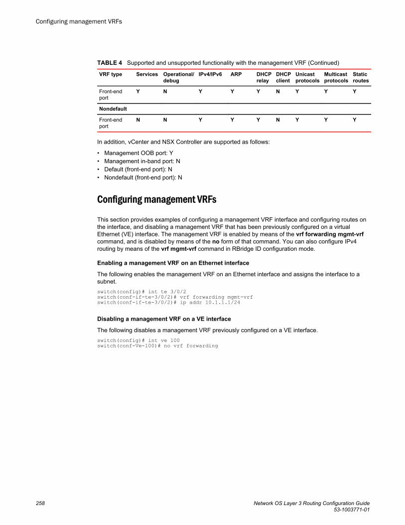
Supported and unsupported functionality with the management VRF (Continued)TABLE 4
VRF type Services Operational/debug
IPv4/IPv6 ARP DHCPrelay
DHCPclient
Unicastprotocols
Multicastprotocols
Staticroutes
Front-endport
Y N Y Y Y N Y Y Y
Nondefault
Front-endport
N N Y Y Y N Y Y Y
In addition, vCenter and NSX Controller are supported as follows:
• Management OOB port: Y• Management in-band port: N• Default (front-end port): N• Nondefault (front-end port): N
Configuring management VRFs
This section provides examples of configuring a management VRF interface and configuring routes onthe interface, and disabling a management VRF that has been previously configured on a virtualEthernet (VE) interface. The management VRF is enabled by means of the vrf forwarding mgmt-vrfcommand, and is disabled by means of the no form of that command. You can also configure IPv4routing by means of the vrf mgmt-vrf command in RBridge ID configuration mode.
Enabling a management VRF on an Ethernet interface
The following enables the management VRF on an Ethernet interface and assigns the interface to asubnet.switch(config)# int te 3/0/2switch(conf-if-te-3/0/2)# vrf forwarding mgmt-vrfswitch(conf-if-te-3/0/2)# ip addr 10.1.1.1/24
Disabling a management VRF on a VE interface
The following disables a management VRF previously configured on a VE interface.switch(config)# int ve 100switch(conf-Ve-100)# no vrf forwarding
Configuring management VRFs
258 Network OS Layer 3 Routing Configuration Guide53-1003771-01
Configuring IPv4 routing for a management VRF on an RBridge interface
Adding default routes to a management VRF (IPv4 or IPv6)
The following configures an IPv4 route subnet for the management VRF, enters address family IPv4configuration mode, and assigns the management VRF to an Ethernet interface.switch(config)# rbridge-id 3switch(confif-rbridge-id-3)# vrf mgmt-vrfswitch(config-vrf-mgmt-vrf)# address-family ipv4 unicastswitch(vrf-ipv4)# ip route 10.1.1.0/32 te 3/0/10The following adds a default IPv4 route to a management VRF.switch(config)# rbridge-id 122switch(config-rbridge-id-122)# vrf mgmt-vrfswitch(config-vrf-mgmt-vrf)# address-family ipv4 unicastswitch(vrf-ipv4-unicast)# ip route 0.0.0.0/0 10.20.232.1The following adds a default IPv6 route to a management VRF.switch(config)# rbridge-id 122switch(config-rbridge-id-122)# vrf mgmt-vrfswitch(config-vrf-mgmt-vrf)# address-family ipv6 unicastswitch(vrf-ipv4-unicast)# ipv6 route ::/0 2620:100:0:fa09::1You can confirm the above by using the show running-config rbridge-id vrf command, as in thefollowing example. You must enter mgmt-vrf manually.sw0# show running-config rbridge-id 122 vrf mgmt-vrfrbridge-id 122vrf mgmt-vrf address-family ipv4 unicast ip route 0.0.0.0/0 10.20.232.1 ! address-family ipv6 unicast ipv6 route ::/0 2620:100:0:fa09::1
Managing management VRFs
There are a variety of show commands that can be used to verify the status of management VRFs, asillustrated in the following examples.
The show vrf command indicates the state (A = active) of the management and default VRFs:switch# show vrfTotal number of VRFs configured: 4VrfName VrfId V4-Ucast V6-UcastRed 3 Enabled -default-vrf 1 Enabled Enabledmgmt-vrf 0 Enabled Enabledre 2 Enabled -
The show ip interface command (with the do keyword on an Ethernet interface) indicates that the VRFon this interface is a management VRF:switch(conf-if-te-3/0/10)# do show ip int te 3/0/10TenGigabitEthernet 3/0/10 is up protocol is upPrimary Internet Address is 10.1.1.1/24 broadcast is 10.1.1.255IP MTU is 1500Proxy Arp is EnabledICMP unreachables are always sentICMP mask replies are never sentIP fast switching is enabledVrf : mgmt-vrf
Managing management VRFs
Network OS Layer 3 Routing Configuration Guide 25953-1003771-01
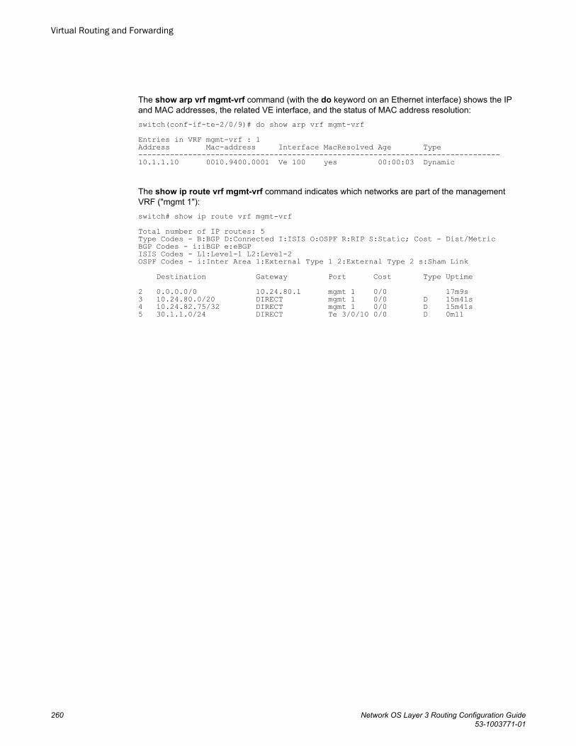
The show arp vrf mgmt-vrf command (with the do keyword on an Ethernet interface) shows the IPand MAC addresses, the related VE interface, and the status of MAC address resolution:switch(conf-if-te-2/0/9)# do show arp vrf mgmt-vrfEntries in VRF mgmt-vrf : 1Address Mac-address Interface MacResolved Age Type--------------------------------------------------------------------------------10.1.1.10 0010.9400.0001 Ve 100 yes 00:00:03 Dynamic
The show ip route vrf mgmt-vrf command indicates which networks are part of the managementVRF ("mgmt 1"):switch# show ip route vrf mgmt-vrfTotal number of IP routes: 5Type Codes - B:BGP D:Connected I:ISIS O:OSPF R:RIP S:Static; Cost - Dist/MetricBGP Codes - i:iBGP e:eBGPISIS Codes - L1:Level-1 L2:Level-2OSPF Codes - i:Inter Area 1:External Type 1 2:External Type 2 s:Sham Link Destination Gateway Port Cost Type Uptime2 0.0.0.0/0 10.24.80.1 mgmt 1 0/0 17m9s3 10.24.80.0/20 DIRECT mgmt 1 0/0 D 15m41s4 10.24.82.75/32 DIRECT mgmt 1 0/0 D 15m41s5 30.1.1.0/24 DIRECT Te 3/0/10 0/0 D 0m11
Virtual Routing and Forwarding
260 Network OS Layer 3 Routing Configuration Guide53-1003771-01
Multi-VRF
● Multi-VRF overview....................................................................................................... 261● Configuring basic Multi-VRF functionality..................................................................... 262
Multi-VRF overviewVirtual Routing and Forwarding (VRF) allows routers to maintain multiple routing tables and forwardingtables on the same router. A Multi-VRF router can run multiple instances of routing protocols with aneighboring router with overlapping address spaces configured on different VRF instances.
Some vendors also use the terms Multi-VRF CE or VRF-Lite for this technology. VRF-Lite provides areliable mechanism for a network administrator to maintain multiple virtual routers on the same device.The goal of providing isolation among different VPN instances is accomplished without the overhead ofheavyweight protocols (such as MPLS) used in secure VPN technologies. Overlapping address spacescan be maintained among the different VPN instances.
Central to VRF-Lite is the ability to maintain multiple VRF tables on the same Provider Edge (PE)Router. VRF-Lite uses multiple instances of a routing protocol such as OSPF or BGP to exchange routeinformation for a VPN among peer PE routers. The VRF-Lite capable PE router maps an input customerinterface to a unique VPN instance. The router maintains a different VRF table for each VPN instanceon that PE router. Multiple input interfaces may also be associated with the same VRF on the router, ifthey connect to sites belonging to the same VPN. This input interface can be a physical interface or avirtual Ethernet interface on a port.
In Multi-VRF deployments:
• Two VRF-capable routers must be directly connected at Layer 3, deploying BGP, OSPF, RIP, orstatic routes.
• Each VRF maintains unique routing and forwarding tables.• Each VRF can be assigned one or more Layer 3 interfaces on a router to be part of the VRF.• Each VRF can be configured with IPv4 address family, IPv6 address family, or both.• A packet’s VRF instance is determined based on the VRF index of the interface on which the packet
is received.• Separate routing protocol instances are required for each VRF instance.• Overlapping address spaces can be configured on different VRF instances.
Multi-VRF deployments provide the flexibility to maintain multiple virtual routers, which are segregatedfor each VRF instance. The following illustrates a generic, high-level topology where different enterprisefunctions are assigned unique VRF instances.
Network OS Layer 3 Routing Configuration Guide 26153-1003771-01
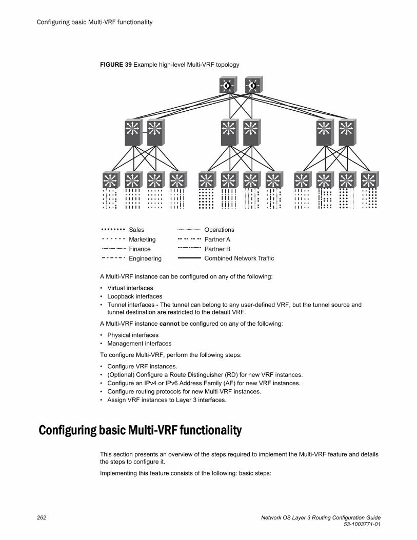
FIGURE 39 Example high-level Multi-VRF topology
A Multi-VRF instance can be configured on any of the following:
• Virtual interfaces• Loopback interfaces• Tunnel interfaces - The tunnel can belong to any user-defined VRF, but the tunnel source and
tunnel destination are restricted to the default VRF.
A Multi-VRF instance cannot be configured on any of the following:
• Physical interfaces• Management interfaces
To configure Multi-VRF, perform the following steps:
• Configure VRF instances.• (Optional) Configure a Route Distinguisher (RD) for new VRF instances.• Configure an IPv4 or IPv6 Address Family (AF) for new VRF instances.• Configure routing protocols for new Multi-VRF instances.• Assign VRF instances to Layer 3 interfaces.
Configuring basic Multi-VRF functionalityThis section presents an overview of the steps required to implement the Multi-VRF feature and detailsthe steps to configure it.
Implementing this feature consists of the following: basic steps:
Configuring basic Multi-VRF functionality
262 Network OS Layer 3 Routing Configuration Guide53-1003771-01
• Defining a VRF routing instance, by means of the vrf command• (Optional) Assigning a Route Distinguisher to a VRF, to set a unique identity to an instance of a VRF
and allow the same IP address to be used in different VPNs without creating any conflict• Assigning a VRF routing instance to one or more virtual or physical interfaces
A VRF can then be configured on VE interfaces over LAG or VLAG.
This section provides a common Multi-VRF configuration, with two possible routing methods to achievethat configuration: eBGP with OSPF, and OSPF alone. The following example topologies shows atypical network that uses the Multi-VRF feature to implement Layer 3 VPNs across two directlyconnected (at Layer 3) Provider Edge (PE) routers. The Customer Edge (CE) routers can be any routeror Layer 3 switch that is capable of running one or many dynamic routing protocols such as BGP,OSPF, or RIP, or even simple static routing. In this example, we use two devices that interconnect allfour CE routers with a single link between the two of them.
NOTEThe single link between the two PEs could also be replaced by a Layer 2 switched network if directphysical connection between the PEs is not possible. The only requirement for the connections is thatthe two PEs be directly connected at Layer 3.
In the topologies that follow, because two different VLANs (10 and 20) have overlapping IP addressranges, communication within each customer's VPN across the two PE routers (that is, between CE1and CE4, and between CE2 and CE3) must be separated by means of two different VRFs ("green" and"red").
The following sections provide two examples of how to implement Multi-VRF by using different routing-protocol configurations:
• Multi-VRF with eBGP and OSPF: eBGP (External BGP) configured between PE1 and PE2, withOSPF (Area 0) configured between the PEs and CEs
• Multi-VRF with OSPF: OSPF (Area 0) configured between PE1 and PE2, with OSPF (Area 1 andArea 2) configured between the PEs and CEs
Multi-VRF with eBGP and OSPFThis section summarizes the topology.
Multi-VRF with eBGP and OSPF
Network OS Layer 3 Routing Configuration Guide 26353-1003771-01
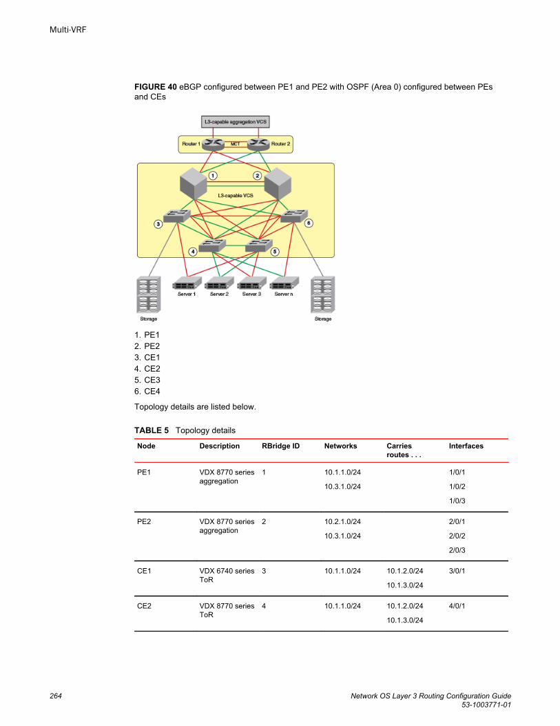
FIGURE 40 eBGP configured between PE1 and PE2 with OSPF (Area 0) configured between PEsand CEs
1. PE12. PE23. CE14. CE25. CE36. CE4
Topology details are listed below.
Topology detailsTABLE 5
Node Description RBridge ID Networks Carriesroutes . . .
Interfaces
PE1 VDX 8770 seriesaggregation
1 10.1.1.0/24
10.3.1.0/24
1/0/1
1/0/2
1/0/3
PE2 VDX 8770 seriesaggregation
2 10.2.1.0/24
10.3.1.0/24
2/0/1
2/0/2
2/0/3
CE1 VDX 6740 seriesToR
3 10.1.1.0/24 10.1.2.0/24
10.1.3.0/24
3/0/1
CE2 VDX 8770 seriesToR
4 10.1.1.0/24 10.1.2.0/24
10.1.3.0/24
4/0/1
Multi-VRF
264 Network OS Layer 3 Routing Configuration Guide53-1003771-01
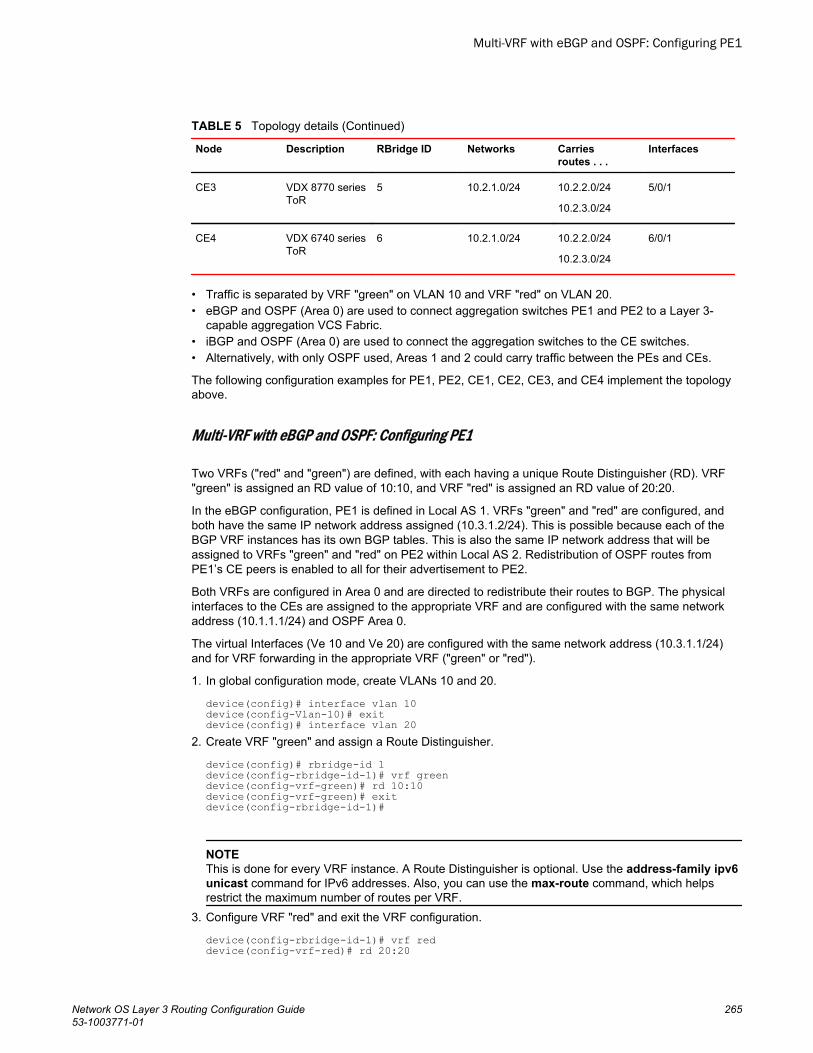
Topology details (Continued)TABLE 5
Node Description RBridge ID Networks Carriesroutes . . .
Interfaces
CE3 VDX 8770 seriesToR
5 10.2.1.0/24 10.2.2.0/24
10.2.3.0/24
5/0/1
CE4 VDX 6740 seriesToR
6 10.2.1.0/24 10.2.2.0/24
10.2.3.0/24
6/0/1
• Traffic is separated by VRF "green" on VLAN 10 and VRF "red" on VLAN 20.• eBGP and OSPF (Area 0) are used to connect aggregation switches PE1 and PE2 to a Layer 3-
capable aggregation VCS Fabric.• iBGP and OSPF (Area 0) are used to connect the aggregation switches to the CE switches.• Alternatively, with only OSPF used, Areas 1 and 2 could carry traffic between the PEs and CEs.
The following configuration examples for PE1, PE2, CE1, CE2, CE3, and CE4 implement the topologyabove.
Multi-VRF with eBGP and OSPF: Configuring PE1
Two VRFs ("red" and "green") are defined, with each having a unique Route Distinguisher (RD). VRF"green" is assigned an RD value of 10:10, and VRF "red" is assigned an RD value of 20:20.
In the eBGP configuration, PE1 is defined in Local AS 1. VRFs "green" and "red" are configured, andboth have the same IP network address assigned (10.3.1.2/24). This is possible because each of theBGP VRF instances has its own BGP tables. This is also the same IP network address that will beassigned to VRFs "green" and "red" on PE2 within Local AS 2. Redistribution of OSPF routes fromPE1’s CE peers is enabled to all for their advertisement to PE2.
Both VRFs are configured in Area 0 and are directed to redistribute their routes to BGP. The physicalinterfaces to the CEs are assigned to the appropriate VRF and are configured with the same networkaddress (10.1.1.1/24) and OSPF Area 0.
The virtual Interfaces (Ve 10 and Ve 20) are configured with the same network address (10.3.1.1/24)and for VRF forwarding in the appropriate VRF ("green" or "red").
1. In global configuration mode, create VLANs 10 and 20.
device(config)# interface vlan 10device(config-Vlan-10)# exitdevice(config)# interface vlan 20
2. Create VRF "green" and assign a Route Distinguisher.
device(config)# rbridge-id 1device(config-rbridge-id-1)# vrf greendevice(config-vrf-green)# rd 10:10device(config-vrf-green)# exitdevice(config-rbridge-id-1)#
NOTEThis is done for every VRF instance. A Route Distinguisher is optional. Use the address-family ipv6unicast command for IPv6 addresses. Also, you can use the max-route command, which helpsrestrict the maximum number of routes per VRF.
3. Configure VRF "red" and exit the VRF configuration.
device(config-rbridge-id-1)# vrf red device(config-vrf-red)# rd 20:20
Multi-VRF with eBGP and OSPF: Configuring PE1
Network OS Layer 3 Routing Configuration Guide 26553-1003771-01
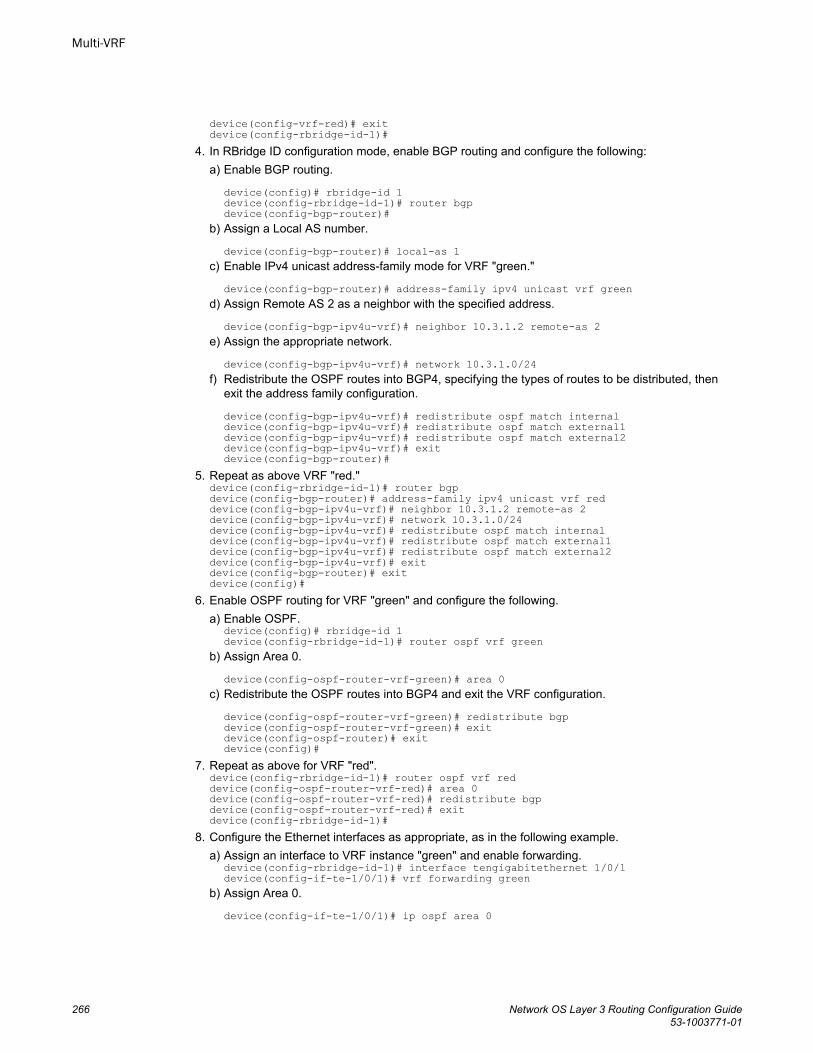
device(config-vrf-red)# exit device(config-rbridge-id-1)#
4. In RBridge ID configuration mode, enable BGP routing and configure the following:a) Enable BGP routing.
device(config)# rbridge-id 1device(config-rbridge-id-1)# router bgpdevice(config-bgp-router)#
b) Assign a Local AS number.
device(config-bgp-router)# local-as 1c) Enable IPv4 unicast address-family mode for VRF "green."
device(config-bgp-router)# address-family ipv4 unicast vrf greend) Assign Remote AS 2 as a neighbor with the specified address.
device(config-bgp-ipv4u-vrf)# neighbor 10.3.1.2 remote-as 2e) Assign the appropriate network.
device(config-bgp-ipv4u-vrf)# network 10.3.1.0/24f) Redistribute the OSPF routes into BGP4, specifying the types of routes to be distributed, then
exit the address family configuration.
device(config-bgp-ipv4u-vrf)# redistribute ospf match internaldevice(config-bgp-ipv4u-vrf)# redistribute ospf match external1device(config-bgp-ipv4u-vrf)# redistribute ospf match external2device(config-bgp-ipv4u-vrf)# exitdevice(config-bgp-router)#
5. Repeat as above VRF "red."device(config-rbridge-id-1)# router bgp device(config-bgp-router)# address-family ipv4 unicast vrf reddevice(config-bgp-ipv4u-vrf)# neighbor 10.3.1.2 remote-as 2device(config-bgp-ipv4u-vrf)# network 10.3.1.0/24device(config-bgp-ipv4u-vrf)# redistribute ospf match internaldevice(config-bgp-ipv4u-vrf)# redistribute ospf match external1device(config-bgp-ipv4u-vrf)# redistribute ospf match external2device(config-bgp-ipv4u-vrf)# exitdevice(config-bgp-router)# exitdevice(config)#
6. Enable OSPF routing for VRF "green" and configure the following.a) Enable OSPF.
device(config)# rbridge-id 1device(config-rbridge-id-1)# router ospf vrf green
b) Assign Area 0.
device(config-ospf-router-vrf-green)# area 0c) Redistribute the OSPF routes into BGP4 and exit the VRF configuration.
device(config-ospf-router-vrf-green)# redistribute bgp device(config-ospf-router-vrf-green)# exitdevice(config-ospf-router)# exitdevice(config)#
7. Repeat as above for VRF "red".device(config-rbridge-id-1)# router ospf vrf reddevice(config-ospf-router-vrf-red)# area 0device(config-ospf-router-vrf-red)# redistribute bgp device(config-ospf-router-vrf-red)# exitdevice(config-rbridge-id-1)#
8. Configure the Ethernet interfaces as appropriate, as in the following example.a) Assign an interface to VRF instance "green" and enable forwarding.
device(config-rbridge-id-1)# interface tengigabitethernet 1/0/1device(config-if-te-1/0/1)# vrf forwarding green
b) Assign Area 0.
device(config-if-te-1/0/1)# ip ospf area 0
Multi-VRF
266 Network OS Layer 3 Routing Configuration Guide53-1003771-01
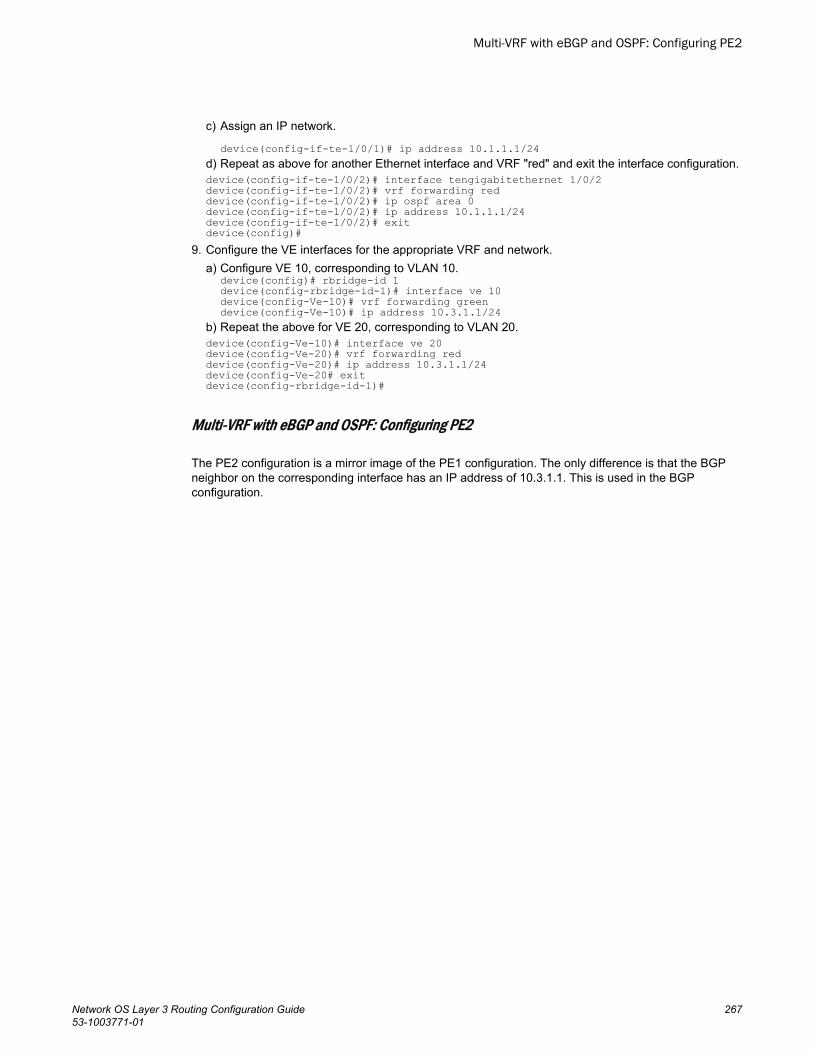
c) Assign an IP network.
device(config-if-te-1/0/1)# ip address 10.1.1.1/24d) Repeat as above for another Ethernet interface and VRF "red" and exit the interface configuration.device(config-if-te-1/0/2)# interface tengigabitethernet 1/0/2 device(config-if-te-1/0/2)# vrf forwarding reddevice(config-if-te-1/0/2)# ip ospf area 0device(config-if-te-1/0/2)# ip address 10.1.1.1/24device(config-if-te-1/0/2)# exitdevice(config)#
9. Configure the VE interfaces for the appropriate VRF and network.a) Configure VE 10, corresponding to VLAN 10.
device(config)# rbridge-id 1device(config-rbridge-id-1)# interface ve 10device(config-Ve-10)# vrf forwarding greendevice(config-Ve-10)# ip address 10.3.1.1/24
b) Repeat the above for VE 20, corresponding to VLAN 20.device(config-Ve-10)# interface ve 20device(config-Ve-20)# vrf forwarding reddevice(config-Ve-20)# ip address 10.3.1.1/24device(config-Ve-20# exitdevice(config-rbridge-id-1)#
Multi-VRF with eBGP and OSPF: Configuring PE2
The PE2 configuration is a mirror image of the PE1 configuration. The only difference is that the BGPneighbor on the corresponding interface has an IP address of 10.3.1.1. This is used in the BGPconfiguration.
Multi-VRF with eBGP and OSPF: Configuring PE2
Network OS Layer 3 Routing Configuration Guide 26753-1003771-01
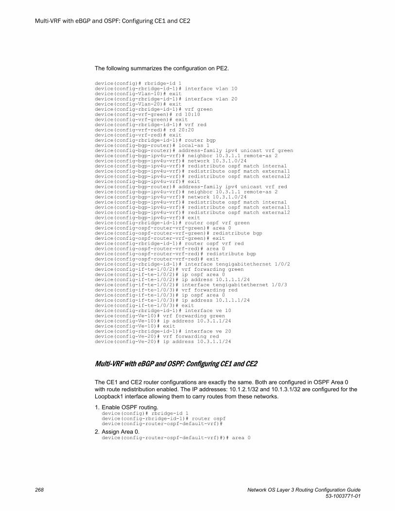
The following summarizes the configuration on PE2.
device(config)# rbridge-id 1device(config-rbridge-id-1)# interface vlan 10device(config-Vlan-10)# exitdevice(config-rbridge-id-1)# interface vlan 20device(config-Vlan-20)# exitdevice(config-rbridge-id-1)# vrf greendevice(config-vrf-green)# rd 10:10device(config-vrf-green)# exitdevice(config-rbridge-id-1)# vrf reddevice(config-vrf-red)# rd 20:20device(config-vrf-red)# exitdevice(config-rbridge-id-1)# router bgpdevice(config-bgp-router)# local-as 1device(config-bgp-router)# address-family ipv4 unicast vrf greendevice(config-bgp-ipv4u-vrf)# neighbor 10.3.1.1 remote-as 2device(config-bgp-ipv4u-vrf)# network 10.3.1.0/24device(config-bgp-ipv4u-vrf)# redistribute ospf match internaldevice(config-bgp-ipv4u-vrf)# redistribute ospf match external1device(config-bgp-ipv4u-vrf)# redistribute ospf match external2device(config-bgp-ipv4u-vrf)# exitdevice(config-bgp-router)# address-family ipv4 unicast vrf reddevice(config-bgp-ipv4u-vrf)# neighbor 10.3.1.1 remote-as 2device(config-bgp-ipv4u-vrf)# network 10.3.1.0/24device(config-bgp-ipv4u-vrf)# redistribute ospf match internaldevice(config-bgp-ipv4u-vrf)# redistribute ospf match external1device(config-bgp-ipv4u-vrf)# redistribute ospf match external2device(config-bgp-ipv4u-vrf)# exitdevice(config-rbridge-id-1)# router ospf vrf greendevice(config-ospf-router-vrf-green)# area 0device(config-ospf-router-vrf-green)# redistribute bgp device(config-ospf-router-vrf-green)# exitdevice(config-rbridge-id-1)# router ospf vrf reddevice(config-ospf-router-vrf-red)# area 0device(config-ospf-router-vrf-red)# redistribute bgp device(config-ospf-router-vrf-red)# exit device(config-rbridge-id-1)# interface tengigabitethernet 1/0/2device(config-if-te-1/0/2)# vrf forwarding greendevice(config-if-te-1/0/2)# ip ospf area 0device(config-if-te-1/0/2)# ip address 10.1.1.1/24device(config-if-te-1/0/2)# interface tengigabitethernet 1/0/3device(config-if-te-1/0/3)# vrf forwarding reddevice(config-if-te-1/0/3)# ip ospf area 0device(config-if-te-1/0/3)# ip address 10.1.1.1/24device(config-if-te-1/0/3)# exitdevice(config-rbridge-id-1)# interface ve 10device(config-Ve-10)# vrf forwarding greendevice(config-Ve-10)# ip address 10.3.1.1/24device(config-Ve-10)# exitdevice(config-rbridge-id-1)# interface ve 20device(config-Ve-20)# vrf forwarding reddevice(config-Ve-20)# ip address 10.3.1.1/24
Multi-VRF with eBGP and OSPF: Configuring CE1 and CE2
The CE1 and CE2 router configurations are exactly the same. Both are configured in OSPF Area 0with route redistribution enabled. The IP addresses: 10.1.2.1/32 and 10.1.3.1/32 are configured for theLoopback1 interface allowing them to carry routes from these networks.
1. Enable OSPF routing.device(config)# rbridge-id 1device(config-rbridge-id-1)# router ospfdevice(config-router-ospf-default-vrf)#
2. Assign Area 0.device(config-router-ospf-default-vrf)#)# area 0
Multi-VRF with eBGP and OSPF: Configuring CE1 and CE2
268 Network OS Layer 3 Routing Configuration Guide53-1003771-01
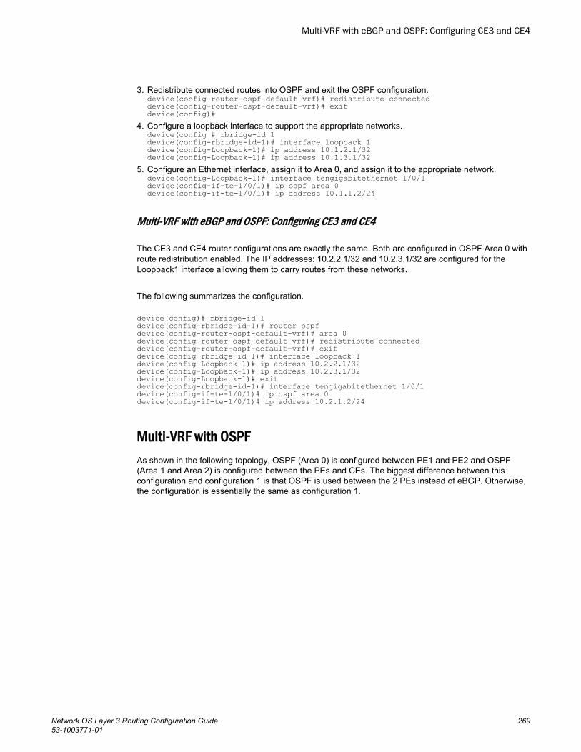
3. Redistribute connected routes into OSPF and exit the OSPF configuration.device(config-router-ospf-default-vrf)# redistribute connected device(config-router-ospf-default-vrf)# exitdevice(config)#
4. Configure a loopback interface to support the appropriate networks.device(config_# rbridge-id 1device(config-rbridge-id-1)# interface loopback 1device(config-Loopback-1)# ip address 10.1.2.1/32device(config-Loopback-1)# ip address 10.1.3.1/32
5. Configure an Ethernet interface, assign it to Area 0, and assign it to the appropriate network.device(config-Loopback-1)# interface tengigabitethernet 1/0/1device(config-if-te-1/0/1)# ip ospf area 0device(config-if-te-1/0/1)# ip address 10.1.1.2/24
Multi-VRF with eBGP and OSPF: Configuring CE3 and CE4
The CE3 and CE4 router configurations are exactly the same. Both are configured in OSPF Area 0 withroute redistribution enabled. The IP addresses: 10.2.2.1/32 and 10.2.3.1/32 are configured for theLoopback1 interface allowing them to carry routes from these networks.
The following summarizes the configuration.
device(config)# rbridge-id 1device(config-rbridge-id-1)# router ospfdevice(config-router-ospf-default-vrf)# area 0 device(config-router-ospf-default-vrf)# redistribute connecteddevice(config-router-ospf-default-vrf)# exitdevice(config-rbridge-id-1)# interface loopback 1device(config-Loopback-1)# ip address 10.2.2.1/32device(config-Loopback-1)# ip address 10.2.3.1/32device(config-Loopback-1)# exitdevice(config-rbridge-id-1)# interface tengigabitethernet 1/0/1 device(config-if-te-1/0/1)# ip ospf area 0device(config-if-te-1/0/1)# ip address 10.2.1.2/24
Multi-VRF with OSPFAs shown in the following topology, OSPF (Area 0) is configured between PE1 and PE2 and OSPF(Area 1 and Area 2) is configured between the PEs and CEs. The biggest difference between thisconfiguration and configuration 1 is that OSPF is used between the 2 PEs instead of eBGP. Otherwise,the configuration is essentially the same as configuration 1.
Multi-VRF with eBGP and OSPF: Configuring CE3 and CE4
Network OS Layer 3 Routing Configuration Guide 26953-1003771-01
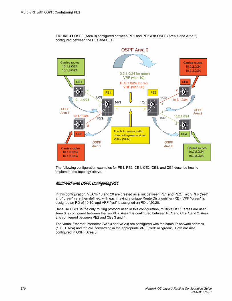
FIGURE 41 OSPF (Area 0) configured between PE1 and PE2 with OSPF (Area 1 and Area 2)configured between the PEs and CEs
The following configuration examples for PE1, PE2, CE1, CE2, CE3, and CE4 describe how toimplement the topology above.
Multi-VRF with OSPF: Configuring PE1
In this configuration, VLANs 10 and 20 are created as a link between PE1 and PE2. Two VRFs ("red"and "green") are then defined, with each having a unique Route Distinguisher (RD). VRF "green" isassigned an RD of 10:10, and VRF "red" is assigned an RD of 20:20.
Because OSPF is the only routing protocol used in this configuration, multiple OSPF areas are used.Area 0 is configured between the two PEs. Area 1 is configured between PE1 and CEs 1 and 2. Area2 is configured between PE2 and CEs 3 and 4.
The virtual Ethernet Interfaces (ve 10 and ve 20) are configured with the same IP network address(10.3.1.1/24) and for VRF forwarding in the appropriate VRF ("red" or "green"). Both are alsoconfigured in OSPF Area 0.
Multi-VRF with OSPF: Configuring PE1
270 Network OS Layer 3 Routing Configuration Guide53-1003771-01
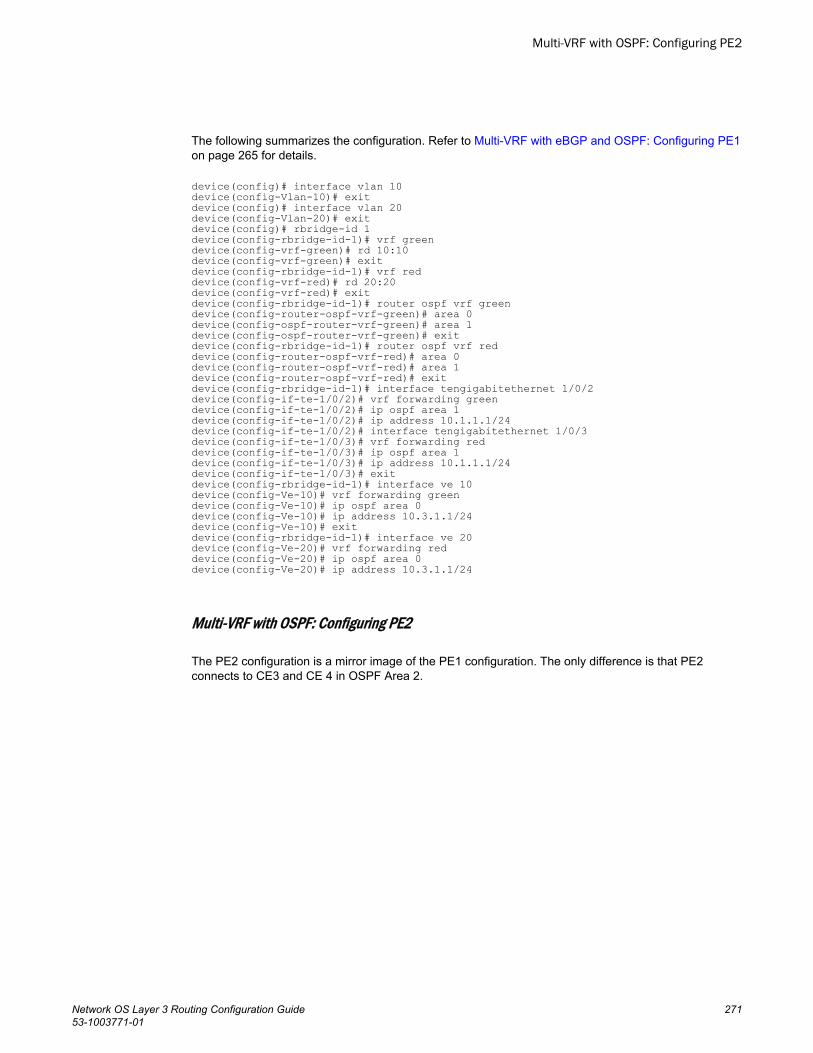
The following summarizes the configuration. Refer to Multi-VRF with eBGP and OSPF: Configuring PE1on page 265 for details.
device(config)# interface vlan 10device(config-Vlan-10)# exitdevice(config)# interface vlan 20device(config-Vlan-20)# exitdevice(config)# rbridge-id 1device(config-rbridge-id-1)# vrf greendevice(config-vrf-green)# rd 10:10device(config-vrf-green)# exitdevice(config-rbridge-id-1)# vrf red device(config-vrf-red)# rd 20:20device(config-vrf-red)# exitdevice(config-rbridge-id-1)# router ospf vrf greendevice(config-router-ospf-vrf-green)# area 0device(config-ospf-router-vrf-green)# area 1 device(config-ospf-router-vrf-green)# exitdevice(config-rbridge-id-1)# router ospf vrf reddevice(config-router-ospf-vrf-red)# area 0device(config-router-ospf-vrf-red)# area 1 device(config-router-ospf-vrf-red)# exitdevice(config-rbridge-id-1)# interface tengigabitethernet 1/0/2device(config-if-te-1/0/2)# vrf forwarding greendevice(config-if-te-1/0/2)# ip ospf area 1device(config-if-te-1/0/2)# ip address 10.1.1.1/24device(config-if-te-1/0/2)# interface tengigabitethernet 1/0/3device(config-if-te-1/0/3)# vrf forwarding reddevice(config-if-te-1/0/3)# ip ospf area 1device(config-if-te-1/0/3)# ip address 10.1.1.1/24device(config-if-te-1/0/3)# exitdevice(config-rbridge-id-1)# interface ve 10device(config-Ve-10)# vrf forwarding greendevice(config-Ve-10)# ip ospf area 0device(config-Ve-10)# ip address 10.3.1.1/24device(config-Ve-10)# exitdevice(config-rbridge-id-1)# interface ve 20 device(config-Ve-20)# vrf forwarding reddevice(config-Ve-20)# ip ospf area 0device(config-Ve-20)# ip address 10.3.1.1/24
Multi-VRF with OSPF: Configuring PE2
The PE2 configuration is a mirror image of the PE1 configuration. The only difference is that PE2connects to CE3 and CE 4 in OSPF Area 2.
Multi-VRF with OSPF: Configuring PE2
Network OS Layer 3 Routing Configuration Guide 27153-1003771-01
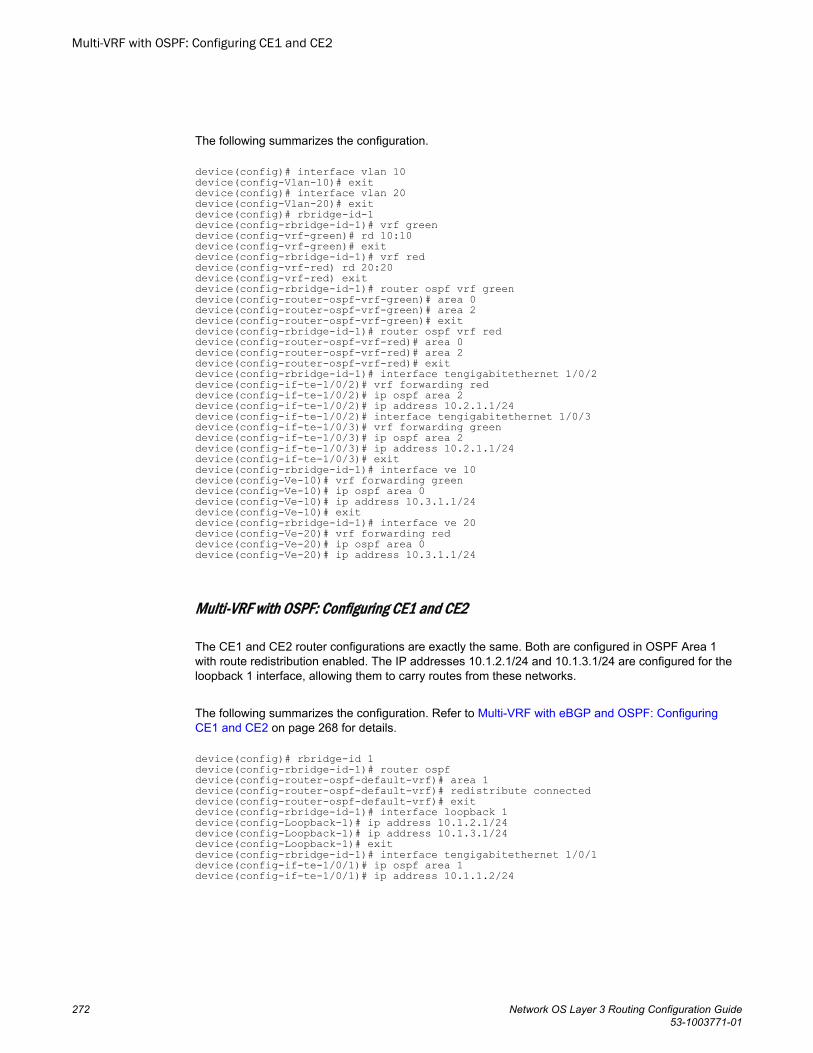
The following summarizes the configuration.
device(config)# interface vlan 10device(config-Vlan-10)# exitdevice(config)# interface vlan 20device(config-Vlan-20)# exitdevice(config)# rbridge-id-1device(config-rbridge-id-1)# vrf greendevice(config-vrf-green)# rd 10:10device(config-vrf-green)# exitdevice(config-rbridge-id-1)# vrf reddevice(config-vrf-red) rd 20:20device(config-vrf-red) exitdevice(config-rbridge-id-1)# router ospf vrf greendevice(config-router-ospf-vrf-green)# area 0device(config-router-ospf-vrf-green)# area 2 device(config-router-ospf-vrf-green)# exitdevice(config-rbridge-id-1)# router ospf vrf reddevice(config-router-ospf-vrf-red)# area 0device(config-router-ospf-vrf-red)# area 2 device(config-router-ospf-vrf-red)# exitdevice(config-rbridge-id-1)# interface tengigabitethernet 1/0/2device(config-if-te-1/0/2)# vrf forwarding reddevice(config-if-te-1/0/2)# ip ospf area 2device(config-if-te-1/0/2)# ip address 10.2.1.1/24device(config-if-te-1/0/2)# interface tengigabitethernet 1/0/3device(config-if-te-1/0/3)# vrf forwarding greendevice(config-if-te-1/0/3)# ip ospf area 2device(config-if-te-1/0/3)# ip address 10.2.1.1/24device(config-if-te-1/0/3)# exitdevice(config-rbridge-id-1)# interface ve 10device(config-Ve-10)# vrf forwarding greendevice(config-Ve-10)# ip ospf area 0device(config-Ve-10)# ip address 10.3.1.1/24device(config-Ve-10)# exitdevice(config-rbridge-id-1)# interface ve 20device(config-Ve-20)# vrf forwarding reddevice(config-Ve-20)# ip ospf area 0device(config-Ve-20)# ip address 10.3.1.1/24
Multi-VRF with OSPF: Configuring CE1 and CE2
The CE1 and CE2 router configurations are exactly the same. Both are configured in OSPF Area 1with route redistribution enabled. The IP addresses 10.1.2.1/24 and 10.1.3.1/24 are configured for theloopback 1 interface, allowing them to carry routes from these networks.
The following summarizes the configuration. Refer to Multi-VRF with eBGP and OSPF: ConfiguringCE1 and CE2 on page 268 for details.
device(config)# rbridge-id 1device(config-rbridge-id-1)# router ospfdevice(config-router-ospf-default-vrf)# area 1 device(config-router-ospf-default-vrf)# redistribute connecteddevice(config-router-ospf-default-vrf)# exitdevice(config-rbridge-id-1)# interface loopback 1device(config-Loopback-1)# ip address 10.1.2.1/24 device(config-Loopback-1)# ip address 10.1.3.1/24device(config-Loopback-1)# exitdevice(config-rbridge-id-1)# interface tengigabitethernet 1/0/1device(config-if-te-1/0/1)# ip ospf area 1device(config-if-te-1/0/1)# ip address 10.1.1.2/24
Multi-VRF with OSPF: Configuring CE1 and CE2
272 Network OS Layer 3 Routing Configuration Guide53-1003771-01
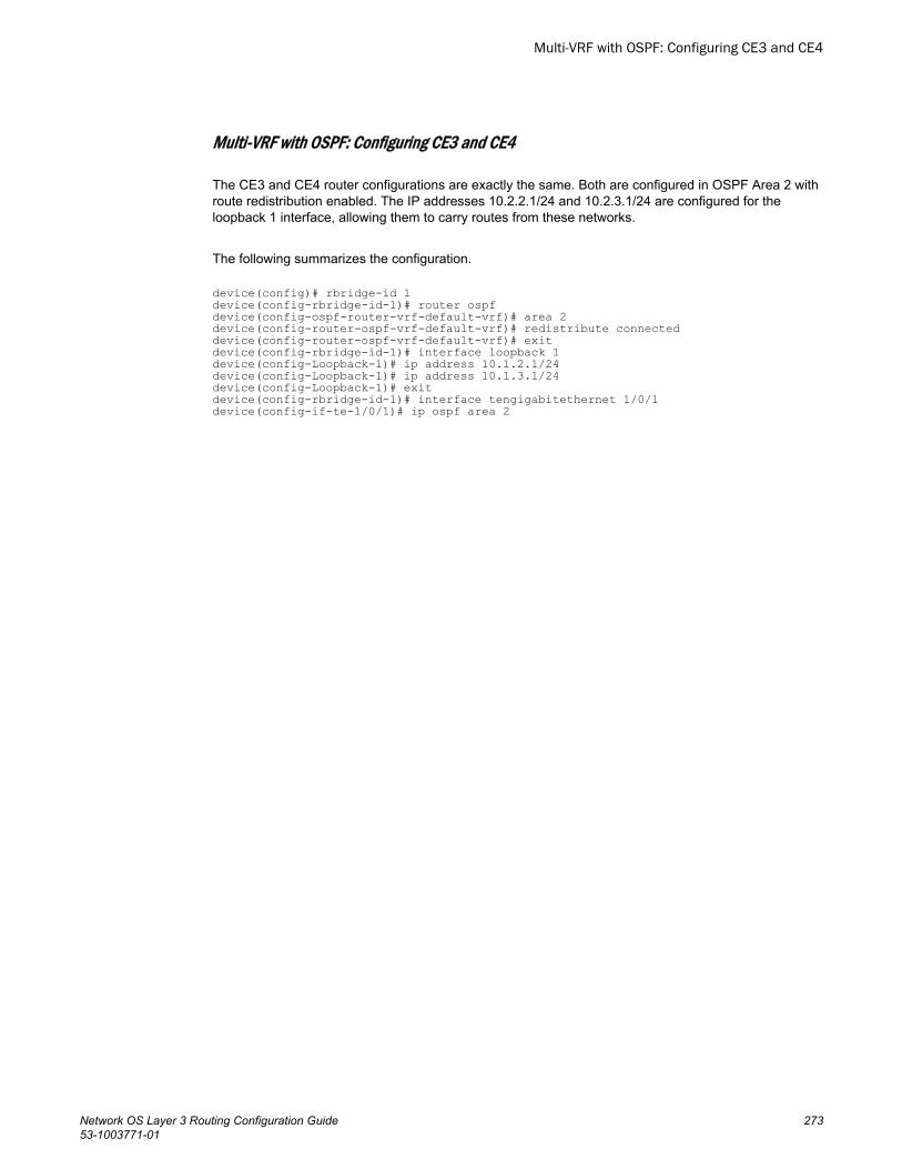
Multi-VRF with OSPF: Configuring CE3 and CE4
The CE3 and CE4 router configurations are exactly the same. Both are configured in OSPF Area 2 withroute redistribution enabled. The IP addresses 10.2.2.1/24 and 10.2.3.1/24 are configured for theloopback 1 interface, allowing them to carry routes from these networks.
The following summarizes the configuration.
device(config)# rbridge-id 1device(config-rbridge-id-1)# router ospfdevice(config-ospf-router-vrf-default-vrf)# area 2device(config-router-ospf-vrf-default-vrf)# redistribute connected device(config-router-ospf-vrf-default-vrf)# exitdevice(config-rbridge-id-1)# interface loopback 1device(config-Loopback-1)# ip address 10.1.2.1/24device(config-Loopback-1)# ip address 10.1.3.1/24device(config-Loopback-1)# exitdevice(config-rbridge-id-1)# interface tengigabitethernet 1/0/1device(config-if-te-1/0/1)# ip ospf area 2
Multi-VRF with OSPF: Configuring CE3 and CE4
Network OS Layer 3 Routing Configuration Guide 27353-1003771-01

Multi-VRF with OSPF: Configuring CE3 and CE4
274 Network OS Layer 3 Routing Configuration Guide53-1003771-01
IPv4 DHCP Relay
● DHCP protocol.............................................................................................................. 275● IP DHCP Relay function................................................................................................275● Brocade IP DHCP relay overview................................................................................. 276● Configuring IP DHCP Relay.......................................................................................... 277● Displaying IP DHCP relay addresses for an interface...................................................279● Displaying IP DHCP Relay addresses on specific switches......................................... 280● Displaying IP DHCP Relay statistics............................................................................. 281● Clearing IP DHCP Relay statistics................................................................................ 282● VRF support.................................................................................................................. 283● High Availability support................................................................................................284
DHCP protocolDynamic Host Configuration Protocol (DHCP) is an IP network protocol that provides networkconfiguration data, such as IP addresses, default routes, DNS server addresses, access control, QoSpolicies, and security policies stored in DHCP server databases to DHCP clients upon request.
You can enable DHCP service on VDX switches so that they can automatically obtain an Ethernet IPaddress, prefix length, and default gateway address from the DHCP server. Refer to the “Configuring anIPv4 address with DHCP” section of the Network OS Administration Guide for more information.
IP DHCP Relay functionDHCP relays are an important feature for large networks as they allow communication between DHCPservers and clients located on different subnets.
In small networks with only one IP subnet, DHCP clients can communicate directly with DHCP servers.Clients located on a different subnet than the DHCP server cannot communicate with that serverwithout obtaining an IP address with appropriate routing information.
By installing a DHCP relay agent on different subnets in a large network, broadcast DHCP packets canbe forwarded from a DHCP client to locate a DHCP server on a remote subnet. The relay agent’s IPaddress is stored in the gateway IP address (GIADDR) field of the DHCP packet, The DHCP serveruses the GIADDR field to find the subnet where the relay agent received the broadcast, and thenassigns IP addresses to that subnet. The DHCP server replies to the client with a unicast message tothe GIADDR address and the relay agent will forward the response to the local network.
Network OS Layer 3 Routing Configuration Guide 27553-1003771-01
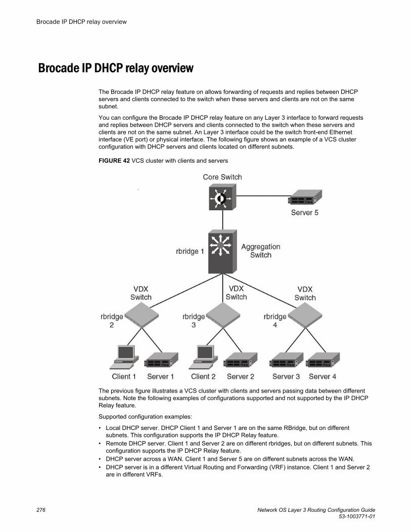
Brocade IP DHCP relay overviewThe Brocade IP DHCP relay feature on allows forwarding of requests and replies between DHCPservers and clients connected to the switch when these servers and clients are not on the samesubnet.
You can configure the Brocade IP DHCP relay feature on any Layer 3 interface to forward requestsand replies between DHCP servers and clients connected to the switch when these servers andclients are not on the same subnet. An Layer 3 interface could be the switch front-end Ethernetinterface (VE port) or physical interface. The following figure shows an example of a VCS clusterconfiguration with DHCP servers and clients located on different subnets.
FIGURE 42 VCS cluster with clients and servers
The previous figure illustrates a VCS cluster with clients and servers passing data between differentsubnets. Note the following examples of configurations supported and not supported by the IP DHCPRelay feature.
Supported configuration examples:
• Local DHCP server. DHCP Client 1 and Server 1 are on the same RBridge, but on differentsubnets. This configuration supports the IP DHCP Relay feature.
• Remote DHCP server. Client 1 and Server 2 are on different rbridges, but on different subnets. Thisconfiguration supports the IP DHCP Relay feature.
• DHCP server across a WAN. Client 1 and Server 5 are on different subnets across the WAN.• DHCP server is in a different Virtual Routing and Forwarding (VRF) instance. Client 1 and Server 2
are in different VRFs.
Brocade IP DHCP relay overview
276 Network OS Layer 3 Routing Configuration Guide53-1003771-01
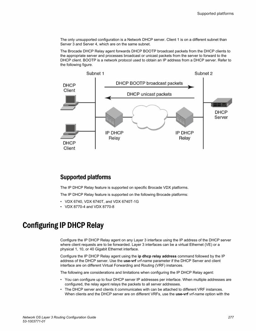
The only unsupported configuration is a Network DHCP server. Client 1 is on a different subnet thanServer 3 and Server 4, which are on the same subnet.
The Brocade DHCP Relay agent forwards DHCP BOOTP broadcast packets from the DHCP clients tothe appropriate server and processes broadcast or unicast packets from the server to forward to theDHCP client. BOOTP is a network protocol used to obtain an IP address from a DHCP server. Refer tothe following figure.
Supported platformsThe IP DHCP Relay feature is supported on specific Brocade VDX platforms.
The IP DHCP Relay feature is supported on the following Brocade platforms:
• VDX 6740, VDX 6740T, and VDX 6740T-1G• VDX 8770-4 and VDX 8770-8
Configuring IP DHCP RelayConfigure the IP DHCP Relay agent on any Layer 3 interface using the IP address of the DHCP serverwhere client requests are to be forwarded. Layer 3 interfaces can be a virtual Ethernet (VE) or aphysical 1, 10, or 40 Gigabit Ethernet interface.
Configure the IP DHCP Relay agent using the ip dhcp relay address command followed by the IPaddress of the DHCP server. Use the use-vrf vrf-name parameter if the DHCP Server and clientinterface are on different Virtual Forwarding and Routing (VRF) instances.
The following are considerations and limitations when configuring the IP DHCP Relay agent:
• You can configure up to four DHCP server IP addresses per interface. When multiple addresses areconfigured, the relay agent relays the packets to all server addresses.
• The DHCP server and clients it communicates with can be attached to different VRF instances.When clients and the DHCP server are on different VRFs, use the use-vrf vrf-name option with the
Supported platforms
Network OS Layer 3 Routing Configuration Guide 27753-1003771-01
ip dhcp relay address command, where vrf-name is the VRF where the DHCP server is located.For more information on VRF support for the IP DHCP Relay, refer to VRF support on page 283.
Perform the following steps to configure an IP DHCP Relay:
1. In privileged EXEC mode, enter the configure terminal command to enter the global configurationmode.
2. Enter the interface command followed by the interface ID to enter the interface configuration modefor the Ve or physical interface where you want to configure the IP DHCP Relay.
3. Enter the ip dhcp relay address ip-addr use-vrf vrf-name command where ip-addr is the IPaddress of the DHCP server. Use the use-vrf vrf-name option if the DHCP server is on a differentVRF instance than the interface where the client is connected.
4. To remove the IP DHCP Relay address enter the no ip dhcp relay address ip-addr use-vrf vrf-name command.
The following is an example of configuring two IP DHCP Relay addresses on a physical 1 GbEinterface in slot 2, port 4 on RBridge ID 1.
NOTEIn this example, the local DHCP server IP address is 10.1.1.2.
switch# configEntering configuration mode terminalswitch(config)# rbridge-id 1switch(config-rbridge-id-1)# int Ve 101switch(config-Ve-101)# ip dhcp relay address 100.1.1.2switch(config-Ve-101)# ip dhcp relay address 12.3.4.6switch(config-Ve-101)# ip dhcp relay address 10.1.1.2
The following is an example of configuring two IP DHCP Relay addresses on virtual Ethernet interface102.
NOTEIn this example, the IP address 3.1.1.255 is the local subnet broadcast address. The relay agentrelays the DHCP packets to the directed broadcast address and all addresses for DHCP serversconfigured on the interface.
switch# configEntering configuration mode terminalswitch(config)# rbridge-id 2switch(config-rbridge-id-2)# int Ve 102switch(config-Ve-102))# ip dhcp relay address 200.1.1.2switch(config-Ve-102)# ip dhcp relay address 10.1.1.255To remove an IP DHCP Relay address use the no option in the ip dhcp relay address ip-addrcommand as in the following example:switch(config-if)# no ip dhcp relay address 200.1.1.2
IPv4 DHCP Relay
278 Network OS Layer 3 Routing Configuration Guide53-1003771-01
Example: DHCP server and client interface on different VRFs
If the DHCP server is on a different VRF than the interface where the client is connected, use the use-vrf vrf-name option in the ip dhcp relay address ip-addr command.
NOTEIf the use-vrf vrf-name option is not used, it is assumed that the DHCP server and client interface areon the same VRF.
switch# configEntering configuration mode terminalswitch(config)# rbridge-id 2switch(config-rbridge-id-2)# int Ve 103switch(config-Ve-103)# ip dhcp relay address 10.1.2.255 use-vrf blueTo remove an IP DHCP Relay address use the no option in the ip dhcp relay address ip-addr use-vrfvrf-name command as in the following example:switch(config-ve-103)# no ip dhcp relay address 10.1.2.255 use-vrf blue
Displaying IP DHCP relay addresses for an interfaceYou can display IP DHCP relay addresses configured on a specific interfaces of a local switch, specificRBridge, or all RBridge IDs in a logical chassis cluster.
To display the IP DHCP relay addresses configured for a switch interface, use the show ip dhcp relayaddress interface command followed by the interface ID to display IP DHCP relay addressesconfigured on a specific interface.
1. Access a switch where an IP DHCP relay has been configured on an interface.2. In privileged EXEC mode, enter the show ip dhcp relay address interface command followed by
the interface ID.
Example: Displaying addresses for local switch interfaces
The following is an example for a 10 GbE interface of a local switch.sw0# show ip dhcp relay address interface te 1/0/24 RBridge Id: 1 ----------------Interface Relay Address VRF Name--------- ------------- --------Te 1/0/24 10.3.4.5 BlueTe 1/0/24 10.5.1.1 Blue
Example: Displaying addresses for a specific interface
The following is an example for a VE interface on a specific switch (RBridge ID 1).sw0# show ip dhcp rel add int ve 300 rbridge-id 1 RBridge Id: 1 ----------------Interface Relay Address VRF Name--------- ------------- --------Ve 300 10.0.1.2 default-vrf
Displaying IP DHCP relay addresses for an interface
Network OS Layer 3 Routing Configuration Guide 27953-1003771-01
Example: Displaying addresses for specific interfaces on range of switches
The following is an example for displaying addresses on for a specific VE interface on a range ofswitches (specified by RBridge IDs) in a logical chassis cluster.
NOTEYou can specify a list of RBridge IDs separated by commas, or a range separated by a dash (forexample, 1-2). No spaces are allowed in the range string. The range does not need to be contiguous(for example, 1-2,5). You can also specify all for all RBridge IDs in the logical chassis cluster.
sw0# show ip dhcp rel add int ve 300 rbridge-id 1,3 RBridge Id: 1 ----------------Interface Relay Address VRF Name--------- ------------- --------Ve 300 10.0.1.2 default-vrfVe 300 10.0.0.5 default-vrf RBridge Id: 3 -------------Interface Relay Address VRF Name--------- ------------- --------Ve 300 20.0.1.2 blueVe 300 30.1.1.5 greenVe 300 40.2.1.1 default-vrf
Displaying IP DHCP Relay addresses on specific switches
Use the show ip dhcp relay address rbridge_id command to display all IP DHCP Relay addressesconfigured on specific switches (specified by RBridge IDs) in a logical chassis cluster. You can use theall keyword to display configured addresses on all RBridge IDs in a cluster.
1. Access a switch where an IP DHCP Relay has been configured.2. In privileged EXEC mode, enter the show ip dhcp relay address rbridge-id rbridge-id command.
Example: Displaying addresses on local RBridge
The following is an example of displaying addresses configured on interfaces of a local switch. Noticethat the RBridge ID is not needed in the command.switch# show ip dhcp relay address RBridge Id: 2 ----------------Interface Relay Address VRF Name--------- ----------- --------Te 2/2/1 10.1.1.1 BlueTe 2/4/2 20.1.1.1 BlueTe 2/5/4 30.1.1.1 Default-vrfTe 2/6/6 40.1.1.1 Green
Displaying IP DHCP Relay addresses on specific switches
280 Network OS Layer 3 Routing Configuration Guide53-1003771-01
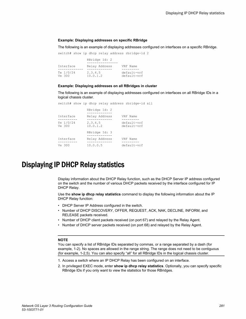
Example: Displaying addresses on specific RBridge
The following is an example of displaying addresses configured on interfaces on a specific RBridge.switch# show ip dhcp relay address rbridge-id 2 RBridge Id: 2 ----------------Interface Relay Address VRF Name------------- ------------- ---------Te 1/0/24 2.3.4.5 default-vrfVe 300 10.0.1.2 default-vrf
Example: Displaying addresses on all RBridges in cluster
The following is an example of displaying addresses configured on interfaces on all RBridge IDs in alogical chassis cluster.switch# show ip dhcp relay address rbridge-id all RBridge Id: 2 -------------Interface Relay Address VRF Name---------- ------------- ---------Te 1/0/24 2.3.4.5 default-vrfVe 300 10.0.1.2 default-vrf RBridge Id: 3 -------------Interface Relay Address VRF Name---------- ------------- ---------Ve 300 10.0.0.5 default-vrf
Displaying IP DHCP Relay statisticsDisplay information about the DHCP Relay function, such as the DHCP Server IP address configuredon the switch and the number of various DHCP packets received by the interface configured for IPDHCP Relay.
Use the show ip dhcp relay statistics command to display the following information about the IPDHCP Relay function:
• DHCP Server IP Address configured in the switch.• Number of DHCP DISCOVERY, OFFER, REQUEST, ACK, NAK, DECLINE, INFORM, and
RELEASE packets received.• Number of DHCP client packets received (on port 67) and relayed by the Relay Agent.• Number of DHCP server packets received (on port 68) and relayed by the Relay Agent.
NOTEYou can specify a list of RBridge IDs separated by commas, or a range separated by a dash (forexample, 1-2). No spaces are allowed in the range string. The range does not need to be contiguous(for example, 1-2,5). You can also specify “all” for all RBridge IDs in the logical chassis cluster.
1. Access a switch where an IP DHCP Relay has been configured on an interface.2. In privileged EXEC mode, enter show ip dhcp relay statistics. Optionally, you can specify specific
RBridge IDs if you only want to view the statistics for those RBridges.
Displaying IP DHCP Relay statistics
Network OS Layer 3 Routing Configuration Guide 28153-1003771-01
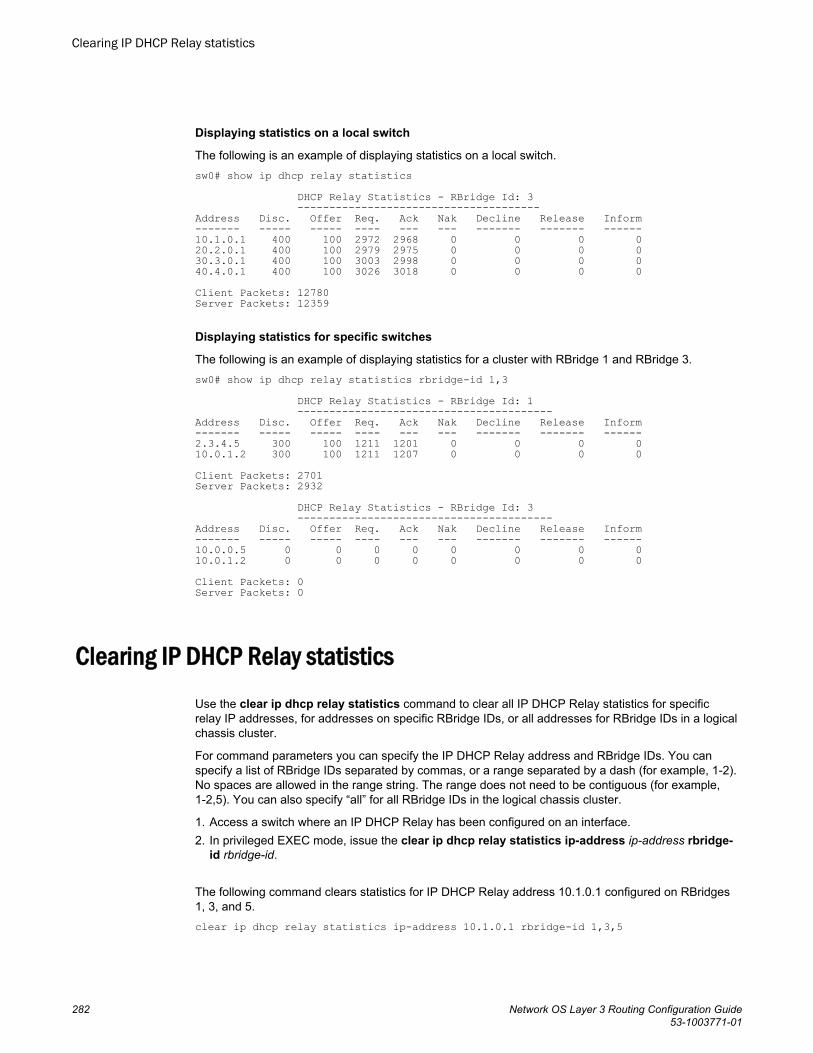
Displaying statistics on a local switch
The following is an example of displaying statistics on a local switch.sw0# show ip dhcp relay statistics DHCP Relay Statistics - RBridge Id: 3 --------------------------------------Address Disc. Offer Req. Ack Nak Decline Release Inform------- ----- ----- ---- --- --- ------- ------- ------10.1.0.1 400 100 2972 2968 0 0 0 020.2.0.1 400 100 2979 2975 0 0 0 030.3.0.1 400 100 3003 2998 0 0 0 040.4.0.1 400 100 3026 3018 0 0 0 0Client Packets: 12780 Server Packets: 12359
Displaying statistics for specific switches
The following is an example of displaying statistics for a cluster with RBridge 1 and RBridge 3.sw0# show ip dhcp relay statistics rbridge-id 1,3 DHCP Relay Statistics - RBridge Id: 1 ----------------------------------------Address Disc. Offer Req. Ack Nak Decline Release Inform------- ----- ----- ---- --- --- ------- ------- ------2.3.4.5 300 100 1211 1201 0 0 0 010.0.1.2 300 100 1211 1207 0 0 0 0Client Packets: 2701Server Packets: 2932 DHCP Relay Statistics - RBridge Id: 3 ----------------------------------------Address Disc. Offer Req. Ack Nak Decline Release Inform------- ----- ----- ---- --- --- ------- ------- ------10.0.0.5 0 0 0 0 0 0 0 0 10.0.1.2 0 0 0 0 0 0 0 0Client Packets: 0Server Packets: 0
Clearing IP DHCP Relay statistics
Use the clear ip dhcp relay statistics command to clear all IP DHCP Relay statistics for specificrelay IP addresses, for addresses on specific RBridge IDs, or all addresses for RBridge IDs in a logicalchassis cluster.
For command parameters you can specify the IP DHCP Relay address and RBridge IDs. You canspecify a list of RBridge IDs separated by commas, or a range separated by a dash (for example, 1-2).No spaces are allowed in the range string. The range does not need to be contiguous (for example,1-2,5). You can also specify “all” for all RBridge IDs in the logical chassis cluster.
1. Access a switch where an IP DHCP Relay has been configured on an interface.2. In privileged EXEC mode, issue the clear ip dhcp relay statistics ip-address ip-address rbridge-
id rbridge-id.
The following command clears statistics for IP DHCP Relay address 10.1.0.1 configured on RBridges1, 3, and 5.clear ip dhcp relay statistics ip-address 10.1.0.1 rbridge-id 1,3,5
Clearing IP DHCP Relay statistics
282 Network OS Layer 3 Routing Configuration Guide53-1003771-01
The following command clears statistics for all IP DHCP Relay addresses on RBridges 1, 3, and 5.clear ip dhcp relay statistics rbridge-id 1,3,5
VRF supportVirtual Routing and Forwarding (VRF) is a technology that controls information flow within a network bypartitioning the network into different logical VRF domains to isolate traffic. This allows a single router orswitch to have multiple containers of routing tables or Forwarding Information Bases (FIBs), with onerouting table for each VRF instance. This permits a VRF-capable router to function as a group ofmultiple virtual routers on the same physical router.
Inter-VRF route leaking allows leaking of specific route prefixes from one VRF instance to another onthe same physical router, which eliminates the need for external routing. In a DHCP setting, routeleaking is controlled through a single DHCP server (which may be on a different VRF). This permitsmultiple VRFs to communicate with that server.
The IP DHCP Relay is supported in configurations where the DHCP server is on the same or differentVRFs than the interface through which the client is connected. When the DHCP server and client are ondifferent VRFs, this is called inter-VRF deployment. For inter-VRF deployment, use the use-vrf vrf-nameoption with the ip dhcp relay address command, where vrf-name is the VRF where the DHCP server islocated.
For more information on VRFs, refer to Virtual Routing and Forwarding on page 247.
Supported VRF configuration examplesFollowing are examples of VRF configurations that are supported for IP DHCP Relay:
• Client interface and DHCP server are on same VRF. As an example:
‐ VE interface 100 in VRF "red"‐ IP address of interface - 3.1.1.1/24‐ IP DHCP Relay address (20.1.1.2) in VRF "red"
• Client interface and DHCP servers are on different VRFs. As an example:
‐ VE interface 100 in default VRF‐ IP address of interface - 3.1.1.1/24‐ IP DHCP Relay address (100.1.1.2) in VRF "blue"‐ IP DHCP Relay address (1.2.3.4.6) in VRF "red"
A maximum of 128 of these inter-VRF IP DHCP Relay address configurations is allowed per node. AVRF route leak configuration is required for these configurations. In the preceding example, a VRFroute leak configuration is required on the default VRF as follows:
‐ ip route 100.1.1.2/32 next-hop-vrf blue 100.1.1.2‐ ip route 12.3.4.6/32 next-hop-vrf red 14.3.4.6
VRF configuration examples to avoidThe following examples of VRF configurations are not recommended for IP DHCP Relay.
• The same IP DHCP Relay address configured on different VRFs. As an example:
VRF support
Network OS Layer 3 Routing Configuration Guide 28353-1003771-01
‐ VE interface 100 in default VRF‐ IP address of interface - 3.1.1.1/24‐ IP DHCP Relay address (30.1.1.2) in VRF "blue"‐ IP DHCP Relay address (30.1.1.2) in VRF "red"
• The same IP DHCP Relay address configured on two interfaces with the same address, and bothinterfaces are on different VRFs. As an example:
‐ VE interface 100 in default VRF‐ IP address of interface - 3.1.1.1/24‐ IP DHCP Relay address (20.1.1.2) in VRF "blue"‐ VE interface 200 in VRF "blue"‐ IP address of interface - 3.1.1.1/24‐ IP DHCP Relay address (20.1.1.2) in VRF "blue"
High Availability supportIP DHCP relay address configurations are maintained when control is switched from the active to thestandby management module (MM) in the Brocade VDX 8770-4 and Brocade VDX 8770-8 chassis.
Two management modules (MMs) provide redundancy on the Brocade VDX 8770-4 and Brocade VDX8770-8 chassis. These modules host the distributed Network OS that provides overall management forthe chassis. If the active module becomes unavailable, the standby module automatically takes overmanagement of the system and becomes the active MM. For more information, refer to the“Configuring High Availability” section of the Network OS Administration Guide.
IP DHCP relay address configurations are maintained on the new active MM and the MM will continueto relay DHCP packets between DHCP clients and servers. IP DHCP relay statistics will not bemaintained, however.
High Availability support
284 Network OS Layer 3 Routing Configuration Guide53-1003771-01
IPv6 DHCP Relay
● DHCPv6 relay agent..................................................................................................... 285● DHCPv6 multicast addresses and UDP ports...............................................................286● DHCPv6 address assignment....................................................................................... 287● DHCPv6 message format............................................................................................. 288● DHCPv6 relay provisioning........................................................................................... 289● Configuring IPv6 DHCP Relay...................................................................................... 290● Displaying DHCPv6 Relay addresses on a specific switch...........................................291● Displaying DHCPv6 Relay addresses for an interface..................................................292● Displaying IPv6 DHCP Relay statistics......................................................................... 293● Clearing IP DHCPv6 Relay statistics............................................................................ 294
DHCPv6 relay agentA DHCPv6 relay agent, which may reside on the client’s link, is used to relay messages between theclient and the server when they are not on the same IPv6 link.
The DHCPv6 relay agent operation is transparent to the client. A DHCPv6 client locates a DHCPv6server using a reserved, link-scoped multicast address. For direct communication between the DHCPv6client and the DHCPv6 server, both the client and the server must be attached to the same link.However, in some situations where ease of management, economy, or scalability is a concern, it isdesirable to allow a DHCPv6 client to send a message to a DHCPv6 server that is not connected to thesame link.
The first figure depicts the relay agent functionality when the relay agent receives DHCP packets from aclient on the same link. The second figure depicts the relay agent functionality when the relay agentreceives DHCP packets from another relay agent on the same link.
Network OS Layer 3 Routing Configuration Guide 28553-1003771-01
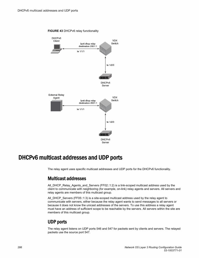
FIGURE 43 DHCPv6 relay functionality
DHCPv6 multicast addresses and UDP portsThe relay agent uses specific multicast addresses and UDP ports for the DHCPv6 functionality.
Multicast addressesAll_DHCP_Relay_Agents_and_Servers (FF02::1:2) is a link-scoped multicast address used by theclient to communicate with neighboring (for example, on-link) relay agents and servers. All servers andrelay agents are members of this multicast group.
All_DHCP_Servers (FF05::1:3) is a site-scoped multicast address used by the relay agent tocommunicate with servers, either because the relay agent wants to send messages to all servers orbecause it does not know the unicast addresses of the servers. To use this address a relay agentmust have an address of sufficient scope to be reachable by the servers. All servers within the site aremembers of this multicast group.
UDP portsThe relay agent listens on UDP ports 546 and 547 for packets sent by clients and servers. The relayedpackets use the source port 547.
DHCPv6 multicast addresses and UDP ports
286 Network OS Layer 3 Routing Configuration Guide53-1003771-01
DHCPv6 address assignmentThe DHCPv6 relay agent informs hosts to use one of the following address assignment methods.
Basic DHCPv6 relay assignmentThe DHCPv6 Relay agent relays the DHCP messages from clients and other relay agents to a list ofdestination addresses, which includes unicast IPv6 addresses, the All_DHCP_Servers multicastaddress, or other user-defined IPv6 multicast group address, on the same VRF as the interface onwhich the client resides or on a different VRF.
Stateful DHCPv6DHCPv6 can be used separately, or in addition to stateless address auto-configuration (SLAAC) toobtain configuration parameters. With stateful DHCPv6, the router can signal the attached clients to useDHCPv6 to acquire an IPv6 address by setting the "O" and "M" bits in the Router Advertisement (RA)message.
The following commands set these bits to support stateful DHCPv6:
ipv6 nd managed-config-flag - When set, clients use DHCPv6 for address configuration.
ipv6 nd other-config-flag - When set, hosts use DHCPv6 to obtain other (non-address) informationwhen set. Relay forwarding supports these flags.
Stateless DHCPv6In stateless DHCPv6, a device uses stateless address auto-configuration (SLAAC) to assign one ormore IPv6 addresses to an interface, while it utilizes DHCPv6 to receive additional parameters, such asDNS or NTP server addresses, that may not be available through SLAAC. This is accomplished bysetting the "O" bit in the relay agent, using the following CLI:
ipv6 nd other-config-flag - When set, hosts use DHCPv6 to obtain other (non-address) information.
DHCPv6 prefix delegationThe DHCPv6 relay agent relays all the DHCPv6 messages (which may or may not contain the DHCPv6options) that are to be relayed across the DHCPv6 client and the server. The relay agent will not accessor extract the information present in the prefix delegation option.
Relay chainingDHCPv6 messages can be relayed through multiple relay agents. The Relay-Reply message from theserver will be relayed back to the client in the same path it took to reach the server.
Relay-message optionThe DHCPV6 relay agent includes the relay message option in all the RELAY-FORW messages.
DHCPv6 address assignment
Network OS Layer 3 Routing Configuration Guide 28753-1003771-01
Remote-ID optionThe DHCPv6 relay agent supports the Remote-ID option (option code 37). No user configuration isnecessary for this method. The DHCPv6 unique identifier (DUID) of relay agent is used as the remoteID.
Interface-ID optionThe DHCPv6 relay agent supports the Interface-ID option to identify the interface on which the clientmessage was received. No user configuration is necessary for this method.
DHCPv6 message formatThe DHCPv6 message format varies from the DHCPv4 message format. This section describes theevents that occur when a DHCPv6 client sends a Solicit message to locate DHCPv6 servers.
• Solicit (1) - A DHCPv6 client sends a Solicit message to locate DHCPv6 servers.• Advertise (2) - A server sends an Advertise message to indicate that it is available for DHCP
service, in response to a Solicit message received from a client.• Request (3) - A client sends a Request message to request configuration parameters, including IP
addresses or delegated prefixes, from a specific server.• Confirm (4) - A client sends a Confirm message to any available server to determine whether the
addresses it was assigned are still appropriate to the link to which the client is connected. Thiscould happen when the client detects either a link-layer connectivity change or if it is powered onand one or more leases are still valid. The confirm message confirms whether the client is still onthe same link or whether if it has been moved. The actual lease(s) are not validated; just the prefixportion of the addresses or delegated prefixes.
• Renew (5) - A client sends a Confirm message to any available server to determine whether theaddresses it was assigned are still appropriate to the link to which the client is connected. Thiscould happen when the client detects either a link-layer connectivity change or if it is powered onand one or more leases are still valid. The confirm message confirms whether the client is still onthe same link or whether it has been moved. The actual lease(s) are not validated; just the prefixportion of the addresses or delegated prefixes.
• Rebind (6) - A client sends a Rebind message to any available server to extend the lifetimes on theaddresses assigned to the client and to update other configuration parameters; this message is sentafter a client receives no response to a Renew message.
• Reply (7) - A server sends a Reply message containing assigned addresses and configurationparameters in response to a Solicit, Request, Renew, Rebind message received from a client. Aserver sends a Reply message containing configuration parameters in response to an Information-request message. A server sends a Reply message in response to a Confirm message confirmingor denying that the addresses assigned to the client are appropriate to the link to which the client isconnected. A server sends a Reply message to acknowledge receipt of a Release or Declinemessage.
• Release (8) - A client sends a Release message to the server that assigned addresses to the clientto indicate that the client will no longer use one or more of the assigned addresses.
• Decline (9) - A client sends a Decline message to a server to indicate that the client has determinedthat one or more addresses assigned by the server are already in use on the link to which the clientis connected.
• Reconfigure (10) - A server sends a Reconfigure message to a client to inform the client that theserver has new or updated configuration parameters, and that the client needs to initiate a Renew/Reply or Information-request/Reply transaction with the server in order to receive the updatedinformation.
DHCPv6 message format
288 Network OS Layer 3 Routing Configuration Guide53-1003771-01
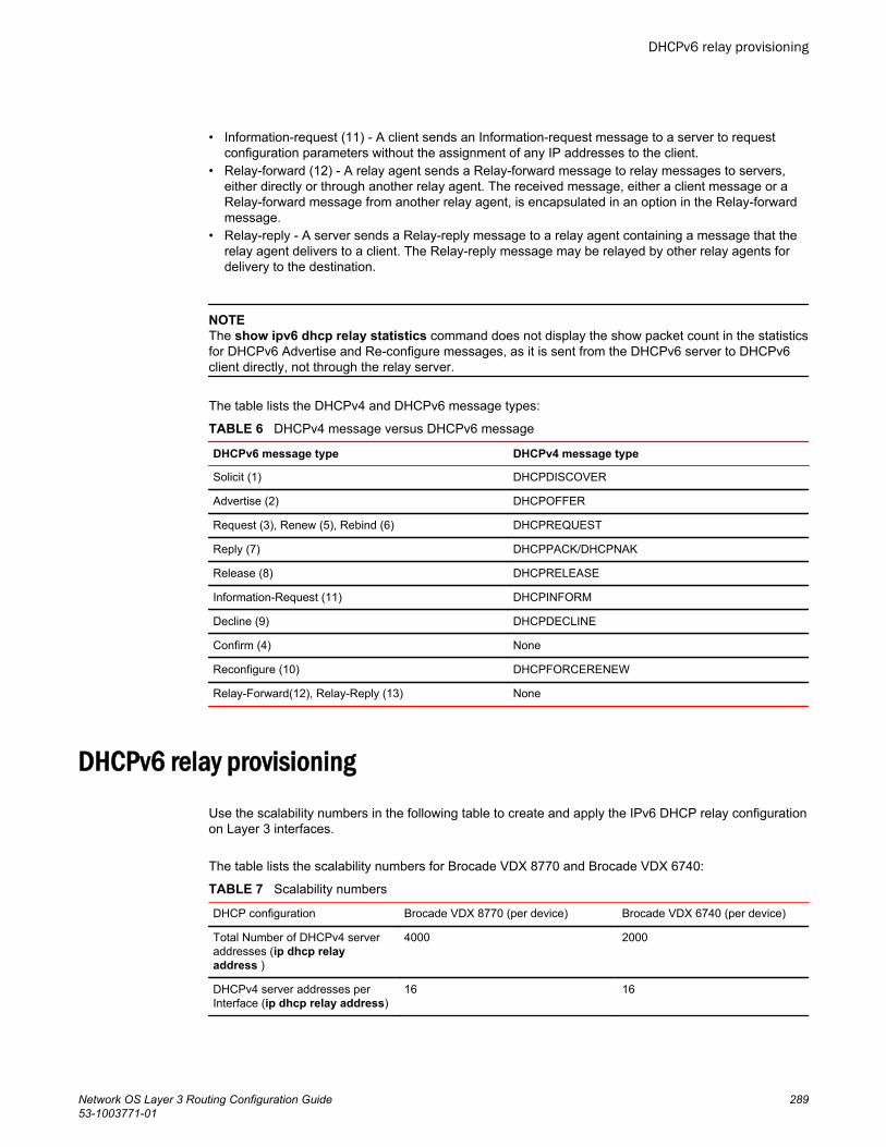
• Information-request (11) - A client sends an Information-request message to a server to requestconfiguration parameters without the assignment of any IP addresses to the client.
• Relay-forward (12) - A relay agent sends a Relay-forward message to relay messages to servers,either directly or through another relay agent. The received message, either a client message or aRelay-forward message from another relay agent, is encapsulated in an option in the Relay-forwardmessage.
• Relay-reply - A server sends a Relay-reply message to a relay agent containing a message that therelay agent delivers to a client. The Relay-reply message may be relayed by other relay agents fordelivery to the destination.
NOTEThe show ipv6 dhcp relay statistics command does not display the show packet count in the statisticsfor DHCPv6 Advertise and Re-configure messages, as it is sent from the DHCPv6 server to DHCPv6client directly, not through the relay server.
The table lists the DHCPv4 and DHCPv6 message types:
DHCPv4 message versus DHCPv6 messageTABLE 6
DHCPv6 message type DHCPv4 message type
Solicit (1) DHCPDISCOVER
Advertise (2) DHCPOFFER
Request (3), Renew (5), Rebind (6) DHCPREQUEST
Reply (7) DHCPPACK/DHCPNAK
Release (8) DHCPRELEASE
Information-Request (11) DHCPINFORM
Decline (9) DHCPDECLINE
Confirm (4) None
Reconfigure (10) DHCPFORCERENEW
Relay-Forward(12), Relay-Reply (13) None
DHCPv6 relay provisioningUse the scalability numbers in the following table to create and apply the IPv6 DHCP relay configurationon Layer 3 interfaces.
The table lists the scalability numbers for Brocade VDX 8770 and Brocade VDX 6740:
Scalability numbersTABLE 7
DHCP configuration Brocade VDX 8770 (per device) Brocade VDX 6740 (per device)
Total Number of DHCPv4 serveraddresses (ip dhcp relayaddress )
4000 2000
DHCPv4 server addresses perInterface (ip dhcp relay address)
16 16
DHCPv6 relay provisioning
Network OS Layer 3 Routing Configuration Guide 28953-1003771-01
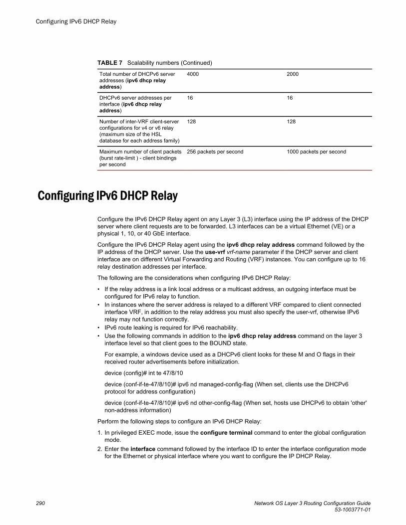
Scalability numbers (Continued)TABLE 7
Total number of DHCPv6 serveraddresses (ipv6 dhcp relayaddress)
4000 2000
DHCPv6 server addresses perinterface (ipv6 dhcp relayaddress)
16 16
Number of inter-VRF client-serverconfigurations for v4 or v6 relay(maximum size of the HSLdatabase for each address family)
128 128
Maximum number of client packets(burst rate-limit ) - client bindingsper second
256 packets per second 1000 packets per second
Configuring IPv6 DHCP RelayConfigure the IPv6 DHCP Relay agent on any Layer 3 (L3) interface using the IP address of the DHCPserver where client requests are to be forwarded. L3 interfaces can be a virtual Ethernet (VE) or aphysical 1, 10, or 40 GbE interface.
Configure the IPv6 DHCP Relay agent using the ipv6 dhcp relay address command followed by theIP address of the DHCP server. Use the use-vrf vrf-name parameter if the DHCP server and clientinterface are on different Virtual Forwarding and Routing (VRF) instances. You can configure up to 16relay destination addresses per interface.
The following are the considerations when configuring IPv6 DHCP Relay:
• If the relay address is a link local address or a multicast address, an outgoing interface must beconfigured for IPv6 relay to function.
• In instances where the server address is relayed to a different VRF compared to client connectedinterface VRF, in addition to the relay address you must also specify the user-vrf, otherwise IPv6relay may not function correctly.
• IPv6 route leaking is required for IPv6 reachability.• Use the following commands in addition to the ipv6 dhcp relay address command on the layer 3
interface level so that client goes to the BOUND state.
For example, a windows device used as a DHCPv6 client looks for these M and O flags in theirreceived router advertisements before initialization.
device (config)# int te 47/8/10
device (conf-if-te-47/8/10)# ipv6 nd managed-config-flag (When set, clients use the DHCPv6protocol for address configuration)
device (conf-if-te-47/8/10)# ipv6 nd other-config-flag (When set, hosts use DHCPv6 to obtain 'other'non-address information)
Perform the following steps to configure an IPv6 DHCP Relay:
1. In privileged EXEC mode, issue the configure terminal command to enter the global configurationmode.
2. Enter the interface command followed by the interface ID to enter the interface configuration modefor the Ethernet or physical interface where you want to configure the IP DHCP Relay.
Configuring IPv6 DHCP Relay
290 Network OS Layer 3 Routing Configuration Guide53-1003771-01
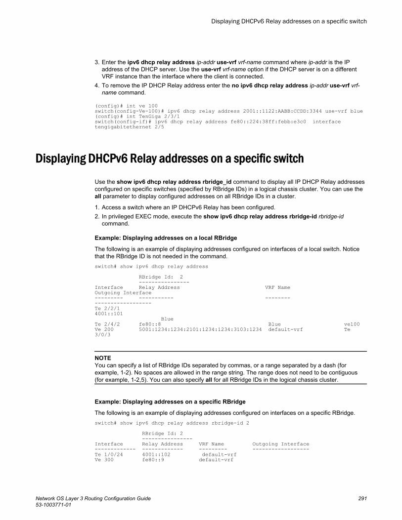
3. Enter the ipv6 dhcp relay address ip-addr use-vrf vrf-name command where ip-addr is the IPaddress of the DHCP server. Use the use-vrf vrf-name option if the DHCP server is on a differentVRF instance than the interface where the client is connected.
4. To remove the IP DHCP Relay address enter the no ipv6 dhcp relay address ip-addr use-vrf vrf-name command.
(config)# int ve 100switch(config-Ve-100)# ipv6 dhcp relay address 2001::1122:AABB:CCDD:3344 use-vrf blue(config)# int TenGiga 2/3/1switch(config-if)# ipv6 dhcp relay address fe80::224:38ff:febb:e3c0 interface tengigabitethernet 2/5
Displaying DHCPv6 Relay addresses on a specific switch
Use the show ipv6 dhcp relay address rbridge_id command to display all IP DHCP Relay addressesconfigured on specific switches (specified by RBridge IDs) in a logical chassis cluster. You can use theall parameter to display configured addresses on all RBridge IDs in a cluster.
1. Access a switch where an IP DHCPv6 Relay has been configured.2. In privileged EXEC mode, execute the show ipv6 dhcp relay address rbridge-id rbridge-id
command.
Example: Displaying addresses on a local RBridge
The following is an example of displaying addresses configured on interfaces of a local switch. Noticethat the RBridge ID is not needed in the command.switch# show ipv6 dhcp relay address RBridge Id: 2 ----------------Interface Relay Address VRF Name Outgoing Interface--------- ----------- -------- ------------------Te 2/2/1 4001::101 BlueTe 2/4/2 fe80::8 Blue ve100Ve 200 5001:1234:1234:2101:1234:1234:3103:1234 default-vrf Te 3/0/3
NOTEYou can specify a list of RBridge IDs separated by commas, or a range separated by a dash (forexample, 1-2). No spaces are allowed in the range string. The range does not need to be contiguous(for example, 1-2,5). You can also specify all for all RBridge IDs in the logical chassis cluster.
Example: Displaying addresses on a specific RBridge
The following is an example of displaying addresses configured on interfaces on a specific RBridge.switch# show ipv6 dhcp relay address rbridge-id 2 RBridge Id: 2 ----------------Interface Relay Address VRF Name Outgoing Interface------------- ------------- --------- ------------------Te 1/0/24 4001::102 default-vrfVe 300 fe80::9 default-vrf
Displaying DHCPv6 Relay addresses on a specific switch
Network OS Layer 3 Routing Configuration Guide 29153-1003771-01
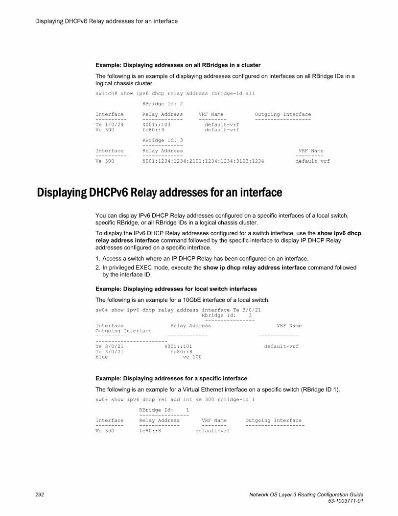
Example: Displaying addresses on all RBridges in a cluster
The following is an example of displaying addresses configured on interfaces on all RBridge IDs in alogical chassis cluster.switch# show ipv6 dhcp relay address rbridge-id all RBridge Id: 2 -------------Interface Relay Address VRF Name Outgoing Interface ---------- ------------- --------- ------------------ Te 1/0/24 4001::103 default-vrfVe 300 fe80::9 default-vrf RBridge Id: 3 -------------Interface Relay Address VRF Name---------- ------------- ---------Ve 300 5001:1234:1234:2101:1234:1234:3103:1234 default-vrf
Displaying DHCPv6 Relay addresses for an interfaceYou can display IPv6 DHCP Relay addresses configured on a specific interfaces of a local switch,specific RBridge, or all RBridge IDs in a logical chassis cluster.
To display the IPv6 DHCP Relay addresses configured for a switch interface, use the show ipv6 dhcprelay address interface command followed by the specific interface to display IP DHCP Relayaddresses configured on a specific interface.
1. Access a switch where an IP DHCP Relay has been configured on an interface.2. In privileged EXEC mode, execute the show ip dhcp relay address interface command followed
by the interface ID.
Example: Displaying addresses for local switch interfaces
The following is an example for a 10GbE interface of a local switch.sw0# show ipv6 dhcp relay address interface Te 3/0/21 Rbridge Id: 3 ----------------Interface Relay Address VRF Name Outgoing Interface--------- ------------- ------------- -----------------------Te 3/0/21 4001::101 default-vrf Te 3/0/21 fe80::8 blue ve 100
Example: Displaying addresses for a specific interface
The following is an example for a Virtual Ethernet interface on a specific switch (RBridge ID 1).sw0# show ipv6 dhcp rel add int ve 300 rbridge-id 1 RBridge Id: 1 ----------------Interface Relay Address VRF Name Outgoing Interface--------- ------------- -------- ------------------- Ve 300 fe80::8 default-vrf
Displaying DHCPv6 Relay addresses for an interface
292 Network OS Layer 3 Routing Configuration Guide53-1003771-01
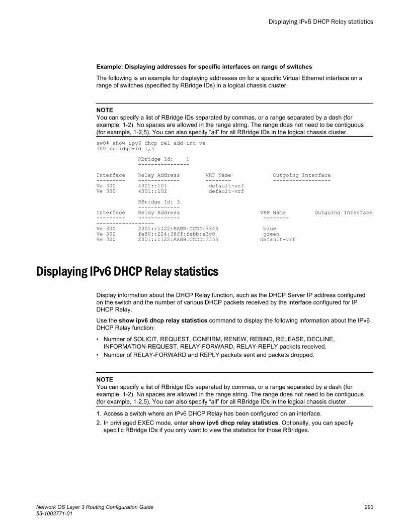
Example: Displaying addresses for specific interfaces on range of switches
The following is an example for displaying addresses on for a specific Virtual Ethernet interface on arange of switches (specified by RBridge IDs) in a logical chassis cluster.
NOTEYou can specify a list of RBridge IDs separated by commas, or a range separated by a dash (forexample, 1-2). No spaces are allowed in the range string. The range does not need to be contiguous(for example, 1-2,5). You can also specify “all” for all RBridge IDs in the logical chassis cluster.
sw0# show ipv6 dhcp rel add int ve 300 rbridge-id 1,3 RBridge Id: 1 ----------------Interface Relay Address VRF Name Outgoing Interface--------- ------------- -------- ------------------ Ve 300 4001::101 default-vrfVe 300 4001::102 default-vrf RBridge Id: 3 -------------Interface Relay Address VRF Name Outgoing Interface--------- ------------- -------- ------------------ Ve 300 2001::1122:AABB:CCDD:3344 blueVe 300 fe80::224:38ff:febb:e3c0 greenVe 300 2001::1122:AABB:CCDD:3355 default-vrf
Displaying IPv6 DHCP Relay statisticsDisplay information about the DHCP Relay function, such as the DHCP Server IP address configuredon the switch and the number of various DHCP packets received by the interface configured for IPDHCP Relay.
Use the show ipv6 dhcp relay statistics command to display the following information about the IPv6DHCP Relay function:
• Number of SOLICIT, REQUEST, CONFIRM, RENEW, REBIND, RELEASE, DECLINE,INFORMATION-REQUEST, RELAY-FORWARD, RELAY-REPLY packets received.
• Number of RELAY-FORWARD and REPLY packets sent and packets dropped.
NOTEYou can specify a list of RBridge IDs separated by commas, or a range separated by a dash (forexample, 1-2). No spaces are allowed in the range string. The range does not need to be contiguous(for example, 1-2,5). You can also specify “all” for all RBridge IDs in the logical chassis cluster.
1. Access a switch where an IPv6 DHCP Relay has been configured on an interface.2. In privileged EXEC mode, enter show ipv6 dhcp relay statistics. Optionally, you can specify
specific RBridge IDs if you only want to view the statistics for those RBridges.
Displaying IPv6 DHCP Relay statistics
Network OS Layer 3 Routing Configuration Guide 29353-1003771-01
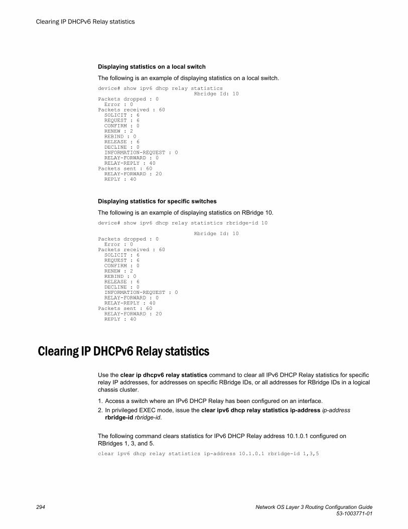
Displaying statistics on a local switch
The following is an example of displaying statistics on a local switch.device# show ipv6 dhcp relay statistics Rbridge Id: 10Packets dropped : 0 Error : 0Packets received : 60 SOLICIT : 6 REQUEST : 6 CONFIRM : 0 RENEW : 2 REBIND : 0 RELEASE : 6 DECLINE : 0 INFORMATION-REQUEST : 0 RELAY-FORWARD : 0 RELAY-REPLY : 40Packets sent : 60 RELAY-FORWARD : 20 REPLY : 40
Displaying statistics for specific switches
The following is an example of displaying statistics on RBridge 10.device# show ipv6 dhcp relay statistics rbridge-id 10 Rbridge Id: 10Packets dropped : 0 Error : 0Packets received : 60 SOLICIT : 6 REQUEST : 6 CONFIRM : 0 RENEW : 2 REBIND : 0 RELEASE : 6 DECLINE : 0 INFORMATION-REQUEST : 0 RELAY-FORWARD : 0 RELAY-REPLY : 40Packets sent : 60 RELAY-FORWARD : 20 REPLY : 40
Clearing IP DHCPv6 Relay statistics
Use the clear ip dhcpv6 relay statistics command to clear all IPv6 DHCP Relay statistics for specificrelay IP addresses, for addresses on specific RBridge IDs, or all addresses for RBridge IDs in a logicalchassis cluster.
1. Access a switch where an IPv6 DHCP Relay has been configured on an interface.2. In privileged EXEC mode, issue the clear ipv6 dhcp relay statistics ip-address ip-address
rbridge-id rbridge-id.
The following command clears statistics for IPv6 DHCP Relay address 10.1.0.1 configured onRBridges 1, 3, and 5.clear ipv6 dhcp relay statistics ip-address 10.1.0.1 rbridge-id 1,3,5
Clearing IP DHCPv6 Relay statistics
294 Network OS Layer 3 Routing Configuration Guide53-1003771-01
Dual-Stack Support
● Understanding dual-stack support................................................................................ 295● Configuring IPv6 addressing and connectivity.............................................................. 297● Configuring IPv6 Neighbor Discovery........................................................................... 304● Configuring MLD snooping............................................................................................310● Monitoring and managing IPv6 networks...................................................................... 317
Understanding dual-stack support
It is not expected that practical IPv6 implementations will be made without consideration for existingIPv4 networks. Making a transition to IPv6 networks without significant challenges or service disruptionsis an incremental, step-by-step process. Interoperability testing must focus, where applicable, on suchareas as firewalls, voice service, wireless service, and application-layer interfaces between popularapplications and implementation of the IPv6 protocol stack. Care must be taken to test server-side andclient-side interoperability not only in pure IPv6 configurations, but also mixed IPv4 and IPv6configurations, across multiple topologies and vendor platforms.
NOTESupport for IPv6 is provided on the Brocade VDX 6740 series and the VDX 8770 series. IPv6functionality is enabled by default.
In a data-center network design, depending on the functionality required, switches at both the accesslayer (if there are no service appliances, such as firewalls, load balancers, and so on at the aggregationlayer) and the aggregation layer (if there are appliances hanging off aggregations switches) require IPv6routing and IPv6/IPv4 termination, as summarized below.
Network OS Layer 3 Routing Configuration Guide 29553-1003771-01
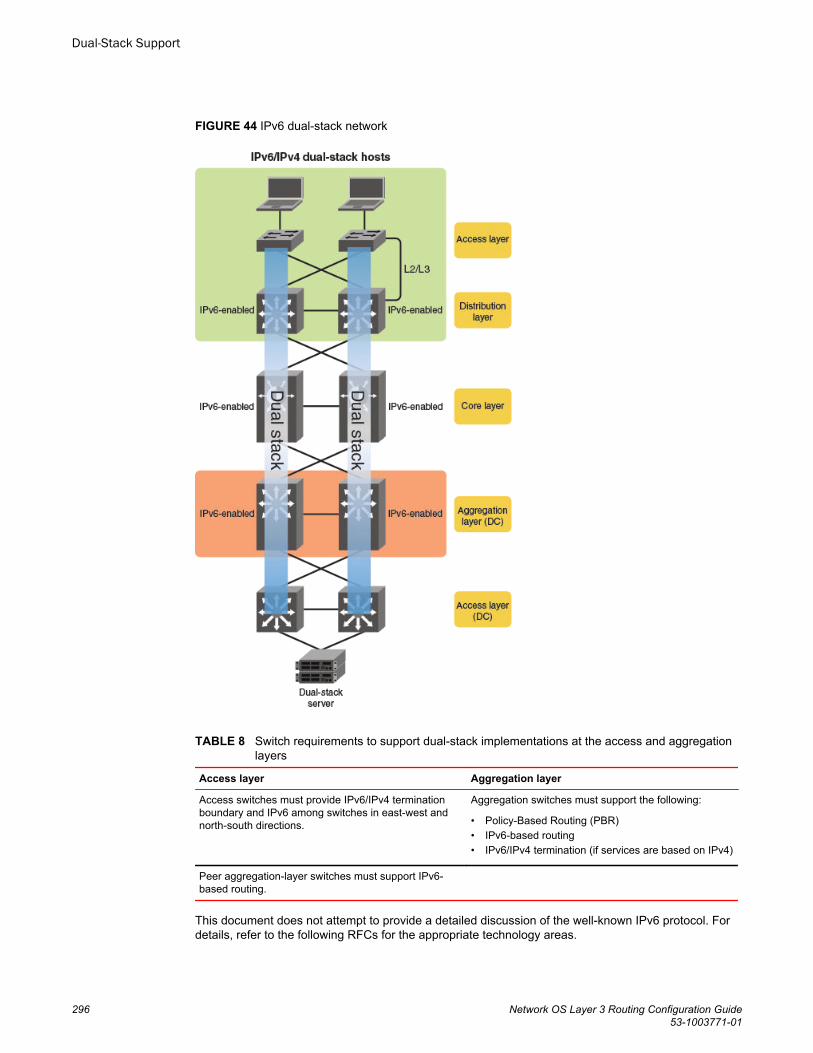
FIGURE 44 IPv6 dual-stack network
Switch requirements to support dual-stack implementations at the access and aggregationlayers
TABLE 8
Access layer Aggregation layer
Access switches must provide IPv6/IPv4 terminationboundary and IPv6 among switches in east-west andnorth-south directions.
Aggregation switches must support the following:
• Policy-Based Routing (PBR)• IPv6-based routing• IPv6/IPv4 termination (if services are based on IPv4)
Peer aggregation-layer switches must support IPv6-based routing.
This document does not attempt to provide a detailed discussion of the well-known IPv6 protocol. Fordetails, refer to the following RFCs for the appropriate technology areas.
Dual-Stack Support
296 Network OS Layer 3 Routing Configuration Guide53-1003771-01
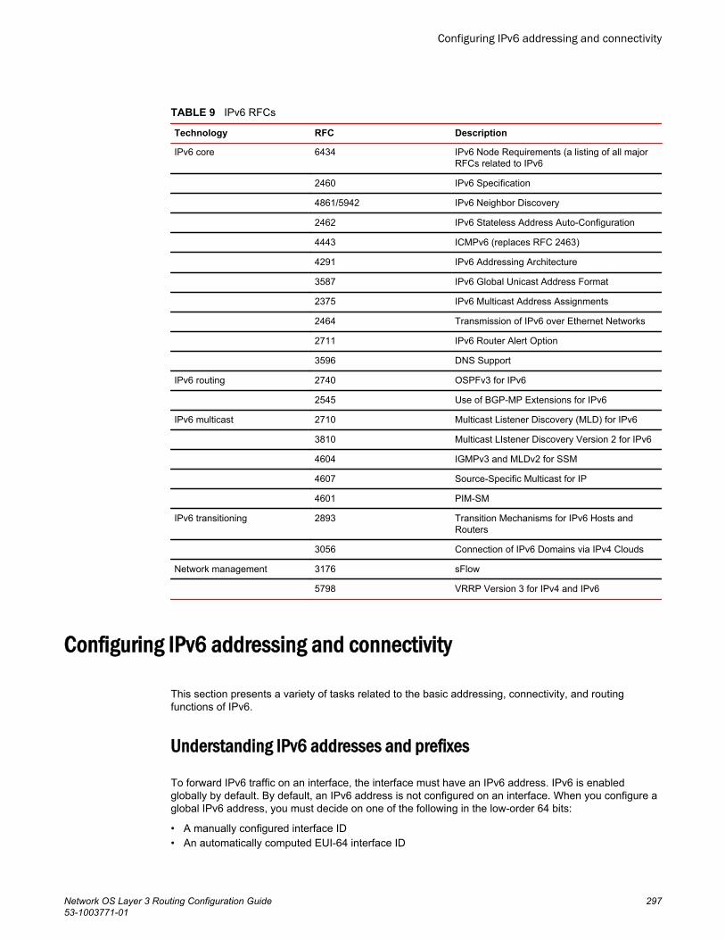
IPv6 RFCsTABLE 9
Technology RFC Description
IPv6 core 6434 IPv6 Node Requirements (a listing of all majorRFCs related to IPv6
2460 IPv6 Specification
4861/5942 IPv6 Neighbor Discovery
2462 IPv6 Stateless Address Auto-Configuration
4443 ICMPv6 (replaces RFC 2463)
4291 IPv6 Addressing Architecture
3587 IPv6 Global Unicast Address Format
2375 IPv6 Multicast Address Assignments
2464 Transmission of IPv6 over Ethernet Networks
2711 IPv6 Router Alert Option
3596 DNS Support
IPv6 routing 2740 OSPFv3 for IPv6
2545 Use of BGP-MP Extensions for IPv6
IPv6 multicast 2710 Multicast Listener Discovery (MLD) for IPv6
3810 Multicast LIstener Discovery Version 2 for IPv6
4604 IGMPv3 and MLDv2 for SSM
4607 Source-Specific Multicast for IP
4601 PIM-SM
IPv6 transitioning 2893 Transition Mechanisms for IPv6 Hosts andRouters
3056 Connection of IPv6 Domains via IPv4 Clouds
Network management 3176 sFlow
5798 VRRP Version 3 for IPv4 and IPv6
Configuring IPv6 addressing and connectivity
This section presents a variety of tasks related to the basic addressing, connectivity, and routingfunctions of IPv6.
Understanding IPv6 addresses and prefixes
To forward IPv6 traffic on an interface, the interface must have an IPv6 address. IPv6 is enabledglobally by default. By default, an IPv6 address is not configured on an interface. When you configure aglobal IPv6 address, you must decide on one of the following in the low-order 64 bits:
• A manually configured interface ID• An automatically computed EUI-64 interface ID
Configuring IPv6 addressing and connectivity
Network OS Layer 3 Routing Configuration Guide 29753-1003771-01
If you assign a link-local IPv6 address to the interface, the address is automatically computed for theinterface. If preferred, you can override the automatically configured link-local address with an addressthat you manually configure.
Configuring a global IPv6 address on an interface does the following:
• Automatically configures an interface ID (a link-local address), if specified• Enables IPv6 on that interface
Additionally, the configured interface automatically joins the following required multicast groups for thatlink:
• Solicited-node multicast group FF02:0:0:0:0:1:FF00::/104 for each unicast address assigned to theinterface
• All-nodes link-local multicast group FF02::1• All-routers link-local multicast group FF02::2
The IPv6 Neighbor Discovery feature sends messages to these multicast groups.
The representation of IPv6 address prefixes is similar to that for IPv4 address prefixes written inClassless Inter-Domain Routing (CIDR) notation. An IPv6 address prefix is represented as ipv6-prefix/prefix-length, where ipv6-prefix is an IPv6 address in any of the notations listed in RFC 4291, andprefix-length is a decimal value specifying how many of the left-most contiguous bits of the addresscomprise the prefix.
For example, the following are legal representations of the 60-bit prefix 20010DB80000CD3(hexadecimal):
• 2001:0DB8:0000:CD30:0000:0000:0000:0000/60• 2001:0DB8::CD30:0:0:0:0/60• 2001:0DB8:0:CD30::/60
Brocade Network OS supports IPv6 prefixes through the ipv6 address command and its variousoptions. You must specify the ipv6-address parameter in hexadecimal by using 16-bit values betweencolons as documented in RFC 4291. You must specify the prefix-length parameter as a decimal value.A slash mark (/) must follow the ipv6-address parameter and precede the prefix-length parameter.
Note the following options:
• The eui-64 keyword configures the global address with an EUI-64 interface ID in the low-order 64bits. The interface ID is automatically constructed in IEEE EUI-64 format by using the MAC addressof the interface. If you do not specify the eui-64 keyword, you must manually configure the 64-bitinterface ID as well as the 64-bit network prefix.
• The optional secondary keyword specifies the address as a secondary address.• The optional anycast keyword configures an anycast address for a set of interfaces that belong to
different nodes
Configuring a global IPv6 address with a manually configuredinterface ID
To configure a global IPv6 address for an interface, including a manually configured interface ID, dothe following.
Configuring a global IPv6 address with a manually configured interface ID
298 Network OS Layer 3 Routing Configuration Guide53-1003771-01
1. In global configuration mode, select an interface.switch(config)# interface te 3/1/1
2. Enter the ipv6 address ipv6-prefix/prefix-length command in interface subtype configuration mode,as in the following example.switch(config-if-te-3/1/1)# ipv6 address 2001:200:12d:1300:240:d0ff:fe48:4672/64
3. Optionally, you can use the secondary keyword with this command to configure one or moresecondary addresses, with the following restrictions:
• You can configure a maximum of 256 secondary addresses.• You cannot configure a secondary address on an interface without first configuring a primary
address.• You cannot delete the primary address (by means of the no ipv6 address command) without first
deleting all secondary addresses.• Secondary addresses are not supported on loopback or management interfaces.
Configuring a global IPv6 address with an automatically computedEUI-64 interface ID
To configure a global IPv6 address with an automatically computed EUI-64 interface ID in the low-order64 bits, do the following.
1. In global configuration mode, select an interface.switch(config)# interface te 3/1/1
2. Enter the ipv6 address ipv6-prefix/prefix-length eui-64 command in interface subtype configurationmode, as in the following example.switch(config-if-te-3/1/1)# ipv6 address 2001:db8:12d:1300::/64 eui-64
NOTEThe eui--64 keyword configures the global address with an EUI-64 interface ID in the low-order 64bits. The interface ID is automatically constructed in IEEE EUI-64 format by means of the interface'sMAC address.
3. Optionally, you can use the secondary keyword with this command to configure one or moresecondary addresses, with the following restrictions:
• You can configure a maximum of 256 secondary addresses.• You cannot configure a secondary address on an interface without first configuring a primary
address.• You cannot delete the primary address (by means of the no ipv6 address command) without first
deleting all secondary addresses.• Secondary addresses are not supported on loopback or management interfaces.
Configuring a link-local IPv6 address
To configure a link-local IPv6 address without configuring a global or site-local address for the interface,do the following.
Configuring a global IPv6 address with an automatically computed EUI-64 interface ID
Network OS Layer 3 Routing Configuration Guide 29953-1003771-01

1. In global configuration mode, select an interface.switch(config)# interface te 3/1/1
2. Enable IPv6 on the interface. You can configure an automatically computed address (by using theipv6 address use-link-local-only command), or an explicit address (by using the ipv6 addresslink-local command. The latter command overrides the automatically computed address.
• The following configures an automatically computed address:switch(config-if-te-3/1/1)# ipv6 address use-link-local-only
• The following configures an explicit address:switch(config-if-te-3/1/1)# ipv6 address fe80::240:d0ff:fe48:4672 link-local
NOTEWhen configuring VLANs that share a common tagged interface with a virtual Ethernet (VE)interface, it is recommended that you override the automatically computed link-local address with amanually configured unique address for the interface. If the interface uses the automaticallycomputed address, which in the case of VE interfaces is derived from a global MAC address, all VEinterfaces will have the same MAC address.
Configuring an IPv6 anycast address
In IPv6, an anycast address is an address for a set of interfaces that belong to different nodes.Sending a packet to an anycast address results in the delivery of the packet to the closest interfacethat has an anycast address. An anycast address looks similar to a unicast address, because it isallocated from the unicast address space. If you assign an IPv6 unicast address to multiple interfaces,it is an anycast address. On the device, you configure an interface assigned an anycast address torecognize the address as an anycast address.
NOTEDuplicate address detection (DAD) is not supported for anycast addresses.
To configure an anycast address on an interface, do the following.
1. In global configuration mode, select an interface.switch(config)# interface te 3/1/1
2. Enter the ipv6 address ipv6-prefix/prefix-length anycast command in interface subtypeconfiguration mode, as in the following example.switch(config-if-te-3/1/1)# ipv6 address 2002::6/64 anycast
Configuring IPv4 and IPv6 protocol stacks
If a device is deployed as an endpoint for an IPv6 over IPv4 tunnel, you must configure the device tosupport IPv4 and IPv6 protocol stacks. Each interface that sends and receives IPv4 and IPv6 trafficmust be configured with an IPv4 address and an IPv6 address.
Do the following to configure an interface to support both IPv4 and IPv6 protocol stacks.
Configuring an IPv6 anycast address
300 Network OS Layer 3 Routing Configuration Guide53-1003771-01
1. Select an interface to support dual stacks.switch(config)# interface te 3/1/1
2. Assign an IPv4 address and mask to the interface.switch(config-if-te-3/1/1)# ip address 192.168.1.1 255.255.255.0
3. Assign an IPv6 address with an automatically computed EUI-64 interface ID.switch(config-if-te-3/1/1)# ipv6 address 2001:200:12d:1300::/64 eui-64
Configuring an IPv6 address family
You can enable IPv6 address-family support for VRF unicast routing, by means of the address-familyipv6 unicast command. This allows you to do the following:
• Configure IPv6 static routes in the specified VRF• Configure IPv6 static neighbors in the specified VRF• Configure any per-VRF routing-protocol options
Do the following to configure an IPv6 address family.
1. In RBridge ID configuration mode, create a VRF instance.switch(config-rbridge-id-1)# vrf red
2. In VRF configuration mode, enable IPv6 address-family unicast support.switch(config-vrf-red)# address-family ipv6 unicast
3. Specify an interface.switch(config)# int te 1/0/10
4. In interface subtype configuration mode, enable VRF forwarding and specify an IPv6 address andprefix length.switch(conf-if-te-1/0/10)# vrf forwarding redswitch(conf-if-te-1/0/10)# ipv6 address 1111::1111/64
If IPv6 address-family unicast support is not enabled, an error is returned as in the following example.switch(conf-if-te-1/0/10)# rb 1 switch(config-rbridge-id-1)# vrf blueswitch(config-vrf-blue)# int te 1/0/10switch(conf-if-te-1/0/10)# vrf forwarding blueswitch(conf-if-te-1/0/10)# ipv6 address 1111::2222/64%% Error: VRF Address Family not configured
Configuring static IPv6 routesYou can configure a static IPv6 route, including an administrative distance, to be redistributed into arouting protocol, but you cannot redistribute routes learned by a routing protocol into the static IPv6routing table.
You must first enable IPv6 on at least one interface in RBridge ID configuration mode by configuring anIPv6 address or explicitly enabling IPv6 on that interface. Static routes are VRF-specific; they implicitlyuse the default VRF unless a nondefault VRF is configured (as in the last of the following examples).
The following tasks illustrate a variety of static IPv6 route configurations.
To configure a static IPv6 route with a destination and next-hop gateway address as a global unicastinterface, perform the following task in global configuration mode.
Configuring an IPv6 address family
Network OS Layer 3 Routing Configuration Guide 30153-1003771-01

1. Enter RBridge ID configuration mode.switch(config)# rbridge-id 54
2. Configure a static IPv6 route with a destination and next-hop gateway address as a global unicastinterface.switch(rbridge-id-54)# ipv6 route 3ffe:abcd::/64 2001::0011:1234
To configure a static IPv6 route with a destination and next-hop gateway address as a global unicastinterface with a metric of 10 and an administrative distance of 110, perform the following task in globalconfiguration mode.
1. Enter RBridge ID configuration mode.switch(config)# rbridge-id 54
2. Configure a static IPv6 route with a destination and next-hop gateway address as a global unicastinterface with a metric of 10 and an administrative distance of 110.switch(rbridge-id-54)# ipv6 route 3ffe:abcd::/64 2001::0011:1234 10 distance 110
NOTEThe value specified for metric is used by the Layer 3 switch to compare this route to other staticroutes in the IPv6 static route table that have the same destination. The metric applies only toroutes that the Layer 3 switch has already placed in the IPv6 static route table. Two or more routesto the same destination with the same metric will load share (as in ECMP load sharing). Valuesrange from 1 through 16 with a default of 1.
The value specified by distance is used by the Layer 3 switch to compare this route with routesfrom other route sources that have the same destination. By default, static routes take precedenceover routes learned by routing protocols. To choose a dynamic route over a static route, configurethe static route with a higher administrative distance than the dynamic route. The range for numberis from 1 through 255, with a default of 1.
To configure a static IPv6 route with a destination global unicast address and next-hop gatewayaddress on a tengigabit Ethernet interface, perform the following task in global configuration mode.
1. Enter RBridge ID configuration mode.switch(config)# rbridge-id 54
2. Configure a static IPv6 route with a destination global unicast address and next-hop gatewayaddress.switch(rbridge-id-54)# ipv6 route 2001:db8::0/32 2001:db8:0:ee44::1
To configure a static IPv6 route with a destination and next-hop gateway address as a link-localaddress on an Ethernet interface, perform the following task in global configuration mode.
1. Enter RBridge ID configuration mode.switch(config)# rbridge-id 54
2. Configure a static IPv6 route with a destination and next-hop gateway address as a link-localaddress on an Ethernet interface.switch(rbridge-id-54)# ipv6 route 3001:1234::/64 fe80::1234
To configure a static IPv6 route with a destination and next-hop gateway address and cause packetsto those addresses to be dropped by shunting them to the "null0" interface, perform the following taskin global configuration mode.
1. Enter RBridge ID configuration mode.switch(config)# rbridge-id 54
2. Configure a static IPv6 route with a destination and next-hop gateway address and cause packetsto those addresses to be dropped by shunting them to the "null0" interface.switch(rbridge-id-54)# ipv6 route 2fe0:1234:5678::/64 null 0
Dual-Stack Support
302 Network OS Layer 3 Routing Configuration Guide53-1003771-01
NOTEThis is called "black-holing." It is recommend that this option be used to block undesirable traffic ortraffic generated in DoS attacks. Traffic is routed dynamically to a "dead" interface. It can also bedirected to a host so that information can be collected for investigation.
To configure a static route and next-hop gateway on a virtual Ethernet interface, perform the followingtask in global configuration mode.
1. Enter RBridge ID configuration mode.switch(config)# rbridge-id 54
2. Configure a static route and next-hop gateway on a virtual Ethernet interface.switch(rbridge-id-54)# ipv6 route 2fe0:1234:5678::/64 ve 500
To configure a static route in a nondefault VRF, perform the following task in global configuration mode.
1. Enter RBridge ID configuration mode.switch(config)# rbridge-id 54
2. Create a nondefault VRF instance, by using the vrf command.switch(rbridge-id-54)# vrf network_70
3. Enter IPv6 address-family configuration mode, by using the address-family ipv6 unicast command.switch(config-vrf-network_70)# address-family ipv6 unicast
4. Configure a static route.switch(vrf-ipv6-unicast)# ipv6 route 2000:1000::/64 3100:1000::1245
NOTEAll other static route configurations, either IPv6 or IPv4, are valid under address-family configurationmode for nondefault VRFs.
For details of the show and clear commands for IPv6 routes, refer to Monitoring and managing IPv6networks on page 317.
Changing the IPv6 MTU
The IPv6 MTU is the maximum length in bytes of an IPv6 packet that can be transmitted on a particularinterface. If an IPv6 packet is longer than the defined MTU, the originating host breaks the packet intofragments that are shorter than that MTU. Per RFC 2460, the minimum IPv6 MTU for any interface is1280 bytes; the default maximum is 1500 bytes. You can change the MTU both at the interface leveland globally.
NOTEIf the size of a jumbo frame received on a port is equal to the maximum frame size and this value isgreater than the IPv4/IPv6 MTU of the outgoing port, the jumbo frame is forwarded to the CPU.
An IPv6 interface can obtain an IPv6 MTU value from any of the following sources:
• Default IPv6 MTU setting• Global IPv6 MTU setting• Interface IPv6 MTU setting
An interface determines the actual MTU value as follows:
Changing the IPv6 MTU
Network OS Layer 3 Routing Configuration Guide 30353-1003771-01
• If an IPv6 interface MTU value is configured, the configured value is used.• If an IPv6 interface value is not configured and N IPv6 global MTU value is configured, the
configured global value is used.• If neither an IPv6 interface value nor an IPv6 global MTU value is configured, the default IPv6 MTU
value of 1500 is used.
You can specify between [1284 - (default-max-frame-size) - 18]. If a nondefault value is configured foran interface, router advertisements include an MTU option. The minimum value you can configure is1298 * (IP6_MIN_MTU + 18 for Ethernet ports).
To change the IPv6 MTU on an interface, use the ipv6 mtu command as in the following example.switch(config)# int te 3/0/1switch(config-if-te-3/0/1)# ipv6 mtu 1280
ATTENTIONTo route packets larger than 2500 bytes (the default for an Ethernet interface), you must also use themtu command to set the same MTU value on the interface as that set by the ipv6 mtu command.Otherwise packets will be dropped . The range for the mtu command is from 1522 through 9219bytes.
Configuring IPv6 Neighbor Discovery
The Neighbor Discovery feature for IPv6 uses ICMPv6 messages to do the following:
• Determine the link-layer address of a neighbor on the same link• Verify that a neighbor is reachable
An IPv6 host is required to listen for and recognize the following addresses, which identify this host:
• Link-local address• Assigned unicast address• Loopback address• All-nodes multicast address• Solicited-node multicast address• Multicast address to all other groups to which it belongs
You can adjust the following IPv6 Neighbor Discovery features:
• Neighbor Solicitation (NS) messages for duplicate address detection (DAD)• Router Advertisement (RA) messages:
‐ The interval between RA messages‐ A lifetime value that indicates a router is advertised as a default router (for use by all nodes on a
given link)‐ Prefixes advertised in RA messages‐ Flags for host stateful autoconfiguration
• The time that an IPv6 node considers a remote node to be reachable (for use by all nodes on agiven link)
• NS interval for reachability
Neighbor Discovery configurations are executed at the interface level, by means of a series of ipv6 ndcommands.
Configuring IPv6 Neighbor Discovery
304 Network OS Layer 3 Routing Configuration Guide53-1003771-01
Neighbor Solicitation and Neighbor Advertisement messages
Neighbor Solicitation (NS) and Neighbor Advertisement (NA) messages enable a node to determine thelink-layer address of another node (neighbor) on the same link. [This function is similar to the functionprovided by the Address Resolution Protocol (ARP) in IPv4.] For example, node 1 on a link wants todetermine the link-layer address of node 2 on the same link. To do so, node 1, the source node,multicasts a NS message. The NS message, which has a value of 135 in the Type field of the ICMPpacket header, contains the following information:
• Source address: IPv6 address of node 1 interface that sends the message
NOTEThe source address is unspecified for DAD.
• Destination address: Solicited-node multicast address (FF02:0:0:0:0:1:FF00::/104) thatcorresponds the IPv6 address of node 2
NOTEFor unicast NS traffic, the destination address is the IPv6 address of the destination. For non-unicastNS traffic, the destination address is the solicited-node's multicast address.
• Link-layer address of node 1• A query for the link-layer address of node 2
After receiving the NS message from node 1, node 2 replies by sending an NA message, which has avalue of 136 in the Type field of the ICMP packet header. The NS message contains the followinginformation:
• Source address: IPv6 address of the node 2 interface that sends the message
NOTEFor solicited advertisements, this is the source address of an invoking NS. Alternatively, if the sourceaddress of the NS is the unspecified address, this is the all-nodes multicast address.
• Destination address: IPv6 address of node 1• Link-layer address of node 2
After node 1 receives the NA message from node 2, nodes 1 and 2 can now exchange packets on thelink.
After the link-layer address of node 2 is determined, node 1 can send NS messages to node 2 to verifythat it is reachable. Also, nodes 1, 2, or any other node on the same link can send a NA message to theall-nodes multicast address (FF02::1) if there is a change in their link-layer address.
Router Advertisement and Router Solicitation messages
Router Advertisement (RA) and Router Solicitation (RS) messages enable a node on a link to discoverthe routers on the same link.
RA messages are sent periodically by a router to provide the following information to hosts:
• Router information such as link-layer address and lifetime of the prefix• IPv6 prefixes for address autoconfiguration• Network information such as MTU and hop limit• Additional information such as reachable time, retransmission time for neighbor solicitations
Neighbor Solicitation and Neighbor Advertisement messages
Network OS Layer 3 Routing Configuration Guide 30553-1003771-01
Each configured interface on a link periodically sends out an RA message, which has a value of 134 inthe Type field of the ICMP packet header, to the all-nodes link-local multicast address (FF02::1).
A configured interface can also send a RA message in response to an RS message from a node onthe same link. This message is sent to the unicast IPv6 address of the node that sent the RSmessage.
At system startup, a host on a link sends an RS message to the all-routers multicast address(FF02::2). Sending an RS message, which has a value of 133 in the Type field of the ICMP packetheader, immediately enables the host to configure its IPv6 address automatically, instead of having towait for the next periodic RA message.
Because a host at system startup typically does not have a unicast IPv6 address, the source addressin the RS message is usually the unspecified IPv6 address (::). If the host has a unicast IPv6 address,the source address is the unicast IPv6 address of the host interface that sends the RS message.
You can configure a variety of RA message parameters at the interface level.
Neighbor Redirect messages
After forwarding a packet, by default a router can send a Neighbor Redirect (NR) message to a host toinform it of a "better" first-hop router. The host receiving the NR message will then readdress thepacket to the better router.
A device sends an NR message only for unicast packets, only to the originating node, and to beprocessed by the node.
An NR message has a value of 137 in the Type field of the ICMP packet header.
Duplicate address detection (DAD)
IPv4 nodes use ARP Request messages and a method called gratuitous ARP to detect a duplicateunicast IPv4 address on the local link. Similarly, IPv6 nodes use Neighbor Solicitation messages todetect the use of duplicate addresses on the local link in a process known as duplicate addressdetection (DAD), as described in RFC 4862.
With IPv4 gratuitous ARP, the Source Protocol Address and Target Protocol Address fields in the ARPRequest message header are set to the IPv4 address for which duplication is being detected. In IPv6DAD, the Target Address field in the Neighbor Solicitation (NS) message is set to the IPv6 address forwhich duplication is being detected. DAD differs from address resolution in the following ways:
• In the DAD NS message, the Source Address field in the IPv6 header is set to the unspecifiedaddress (::). The address being queried for duplication cannot be used until it is determined thatthere are no duplicates.
• In the Neighbor Advertisement (NA) reply to a DAD NS message, the Destination Address in theIPv6 header is set to the link-local all-nodes multicast address (FF02::1). The Solicited flag in theNA message is set to 0. Because the sender of the DAD NS message is not using the desired IPaddress, it cannot receive unicast NA messages. Therefore, the NA message is multicast.
• Upon receipt of the multicast NA message with the Target Address field set to the IP address forwhich duplication is being detected, the node disables the use of the duplicate IP address on theinterface. If the node does not receive an NA message that defends the use of the address, itinitializes the address on the interface.
An IPv6 node does not perform DAD for anycast addresses. Anycast addresses are not unique to anode. Network OS does not perform DAD for IPv6 addresses configured on loopback interfaces.
Although the stateless autoconfiguration feature assigns the 64-bit interface ID portion of an IPv6address by using the MAC address of the host's NIC, duplicate MAC addresses can occur. Therefore,
Neighbor Redirect messages
306 Network OS Layer 3 Routing Configuration Guide53-1003771-01
the DAD feature verifies that a unicast IPv6 address is unique before it is assigned to a host interface bythe stateless autoconfiguration feature. DAD verifies that a unicast IPv6 address is unique.
If DAD identifies a duplicate unicast IPv6 address, the address is not used. If the duplicate address isthe link-local address of the host interface, the interface stops processing IPv6 packets.
Setting Neighbor Solicitation parameters for DAD
Although the stateless autoconfiguration feature assigns the 64-bit interface ID portion of an IPv6address by using the MAC address of the host’s NIC, duplicate MAC addresses can occur. Therefore,the duplicate address detection (DAD) feature verifies that a unicast IPv6 address is unique before it isassigned to a host interface by the stateless autoconfiguration feature. DAD verifies that a unicast IPv6address is unique.
If DAD identifies a duplicate unicast IPv6 address, the address is not used. If the duplicate address isthe link-local address of the host interface, the interface stops processing IPv6 packets.
You can configure the following Neighbor Solicitation (NS) message parameters that affect DAD while itverifies that a tentative unicast IPv6 address is unique:
• The number of consecutive NS messages that DAD sends on an interface. By default, DAD sendstwo NS messages without any follow-up messages.
• The interval in seconds at which DAD sends a NS message on an interface. By default, DAD sendsan NS message every 1 second.
NOTEFor the interval at which DAD sends an NS message on an interface, the router uses seconds as theunit of measure instead of milliseconds.
For example, to change the number of NS messages sent on Ethernet interface 3/1/1 to 3 and theinterval between the transmission of the two messages to 4 seconds, do the following
1. In global configuration mode, select an interface.switch(config)# interface te 3/1/1
2. Enter the ipv6 nd dad attempt number command to set the number of solicitation messages sent onthe interface.switch(config-if-te-3/1/1)# ipv6 nd dad attempt 3
NOTETo disable DAD on an interface, set the number of attempts to 0.
3. Enter the ipv6 nd dad time seconds command to set the interval between the messages.switch(config-if-te-3/1/1)# ipv6 nd dad time 4
NOTEIt is recommended that you do not specify intervals that are very short in normal IPv6 operation.When a nondefault interval value is configured, that interval is both advertised and used by the routeritself.
Setting Neighbor Solicitation parameters for DAD
Network OS Layer 3 Routing Configuration Guide 30753-1003771-01
Configuring IPv6 static neighbor entries
In some cases a neighbor cannot be reached by means of Neighbor Discovery. To resolve this youcan add a static entry to the ND cache, causing a neighbor to reachable at all times. (A static IPv6 NDentry is like a static IPv4 ARP entry.)
For example, use the ipv6 neighbor command in interface subtype configuration mode to add a staticentry for a neighbor with IPv6 address 2001:db8:2678::2 and link-layer address 0000.002b.8641,reachable through interface te 3/0/1.switch(config-if-te-3/0/1)# ipv6 neighbor 2001:db8:2678::2 0000.002b.8641
Setting IPv6 Router Advertisement parameters
You can adjust the following parameters for Router Advertisement (RA) messages:
• The interval (in seconds) at which an interface sends RA messages. By default, an interface sendsan RA message randomly, every 200 to 600 seconds.
• The "router lifetime" value, which is included in RA messages sent from a particular interface. Thevalue (in seconds) indicates whether the router is advertised as a default router on this interface. Ifyou set the value of this parameter to 0, the router is not advertised as a default router on aninterface. If you set this parameter to a value that is not 0, the router is advertised as a defaultrouter on this interface. By default, the router lifetime value included in router advertisementmessages sent from an interface is 1800 seconds.
NOTEWhen adjusting these parameter settings, it is recommended that you set the interval between routeradvertisement transmission to be less than or equal to the router lifetime value if the router isadvertised as a default router.
For example, to adjust the interval of router advertisements to specify the range matching theconfiguration and the router lifetime value to 1900 seconds on an interface, enter the followingcommands.
1. In global configuration mode, select an interface.switch(config)# interface te 3/1/1
2. Enter the ipv6 nd ra-interval command to set a maximum interval range and minimum interval atwhich RA messages are sent.switch(config-if-te-3/1/1)# ipv6 nd ra-interval 1200 min 400
3. Enter the ipv6 nd ra-lifetime number command to set the RA message lifetime.switch(config-if-te-3/1/1)# ipv6 nd ra-lifetime 1900
4. Enter the ipv6 nd hoplimit command to specify a nondefault hop limit.switch(config-if-te-3/1/1)# ipv6 nd hoplimit 32
5. Enter the ipv6 nd mtu command to specify a nondefault MTU.switch(config-if-te-3/1/1)# ipv6 nd mtu 2400
Controlling prefixes advertised in IPv6 Router Advertisementmessages
By default, Router Advertisement (RA) messages include prefixes configured as addresses oninterfaces by means of the ipv6 address command. You can use the ipv6 nd prefix command to
Configuring IPv6 static neighbor entries
308 Network OS Layer 3 Routing Configuration Guide53-1003771-01
control exactly which prefixes are included in RA messages. The prefix is associated with a valid,preferred lifetime. For a prefix derived from the global address, the lifetime value is infinite(0xFFFFFFFF).
RA messages also use the following parameters:
• Valid lifetime -- (Mandatory) The time interval (in seconds) in which the specified prefix is advertisedas valid. The default is 2592000 seconds (30 days). When the timer expires, the prefix is no longerconsidered to be valid.
• Preferred lifetime -- (Mandatory) The time interval (in seconds) in which the specified prefix isadvertised as preferred. The default is 604800 seconds (7 days). When the timer expires, the prefixis no longer considered to be preferred.
• Onlink flag -- (Optional) If this flag is set, the specified prefix is assigned to the link upon which it isadvertised. Nodes sending traffic to addresses that contain the specified prefix consider thedestination to be reachable on the local link.
• Autoconfiguration flag -- (Optional) If this flag is set, the stateless autoconfiguration feature can usethe specified prefix in the automatic configuration of 128-bit IPv6 addresses for hosts on the locallink.
The following illustrates the execution of the ipv6 nd prefix command.
1. In global configuration mode, select an interface.switch(config)# interface te 3/1/1
2. Enter the ipv6 nd prefixcommand and specify a prefix and prefix length.switch(config-if-te-3/1/1)# ipv6 nd prefix 2ffe:1111::/64
NOTEValid and preferred lifetimes are default values, which are 2592000 and 604800, respectively.
Setting flags in IPv6 Router Advertisement messages
An IPv6 Router Advertisement (RA) message can include the following flags:
• Managed Address Configuration -- This flag indicates to hosts on a local link whether they shoulduse the stateful autoconfiguration feature to get IPv6 addresses for their interfaces. If the flag is set,the hosts use stateful autoconfiguration to get addresses as well as non-IPv6-address information. Ifthe flag is not set, the hosts do not use stateful autoconfiguration to get addresses, and whether thehosts can get information that is not address-related from stateful autoconfiguration is determined bythe setting of the Other Stateful Configuration flag.
• Other Stateful Configuration -- This flag indicates to hosts on a local link whether they canautoconfiguration information that is not address-related. If the flag is set, the hosts can use statefulautoconfiguration to get non-IPv6-address information.
NOTEWhen determining whether hosts can use stateful autoconfiguration to get non-IPv6-addressinformation, use a Managed Address Configuration flag to override an unset Other StatefulConfiguration flag. In this situation, the hosts can obtain non-IPv6-address information. However, if theManaged Address Configuration flag is not set and the Other Stateful Configuration flag is set, then thesetting of the Other Stateful Configuration flag is used.
By default, the Managed Address Configuration and Other Stateful Configuration flags are not set in RAmessages. For example, to set these flags in router advertisement messages sent from an interface,enter the following commands.
Setting flags in IPv6 Router Advertisement messages
Network OS Layer 3 Routing Configuration Guide 30953-1003771-01
1. In global configuration mode, select an interface.switch(config)# interface te 3/1/1
2. Enter the ipv6 nd managed-config-flagcommand to enable hosts on a local link to use statefulautoconfiguration to get addresses as well as non-IPv6-address information.switch(config-if-te-3/1/1)# ipv6 nd managed-config-flag
3. Enter the ipv6 nd other-config-flagcommand to enable hosts on a local link to use statefulautoconfiguration non-IPv6-address information.switch(config-if-te-3/1/1)# ipv6 nd other-config-flag
Configuring MLD snooping
A Layer 2 switch forwards all multicast control packets and data received on all the member ports of aVLAN interface. This approach, though simple, is not bandwidth efficient, because only a subset ofmember ports may be connected to devices interested in receiving those multicast packets. In theworst-case scenario the data are forwarded to all port members of a VLAN with a large number ofmember ports, even if only a single VLAN member is interested in receiving the data. Such scenarioscan lead to loss of throughput for a switch when it receives high-rate multicast data traffic.
Multicast Listener Discovery (MLD) snooping is a multicast-constraining mechanism that runs on Layer2/Layer3 devices to manage and control IPV6 multicast groups. MLD snooping provides functionalityfor IPv6 that is similar to IGMP snooping for IPv4, by sending IPV6 multicast traffic only to interestedlisteners. By listening to and analyzing MLD messages, a Layer 2 device running MLD snoopingestablishes mappings between ports and multicast MAC addresses or multicast IP addresses, andforwards multicast data accordingly. Multicast routers in a network are found by means of either staticconfiguration, dynamic learning, or PIM hello-based mrouter detection.
NOTEThis release supports the IPv6 version of MLDv1 snooping for devices in both logical chassis andfabric cluster modes.
In any given subnet, one multicast router is elected to act as an MLD querier. The MLD querier sendsout the following types of queries to hosts:
• General query: Querier asks whether any host is listening to any group.• Group-specific query: Querier asks whether any host is listening to a specific multicast group. This
query is sent in response to a host leaving the multicast group and allows the router to determinequickly whether any remaining hosts are interested in the group.
Hosts that are multicast listeners send the following kinds of messages:
• Report message: Indicates that the host wants to join a particular multicast group.• Done message: Indicates that the host wants to leave a particular multicast group.
MLD traffic is forwarded as follows:
• MLD general queries received on a multicast-router interface are forwarded to all other interfaces inthe VLAN.
• MLD group-specific queries received on a multicast-router interface are forwarded to only thoseinterfaces in the VLAN that are members of the group.
• MLD report or done messages received on a host interface are forwarded to multicast-routerinterfaces in the same VLAN, but not to other host interfaces in the VLAN.
Configuring MLD snooping
310 Network OS Layer 3 Routing Configuration Guide53-1003771-01
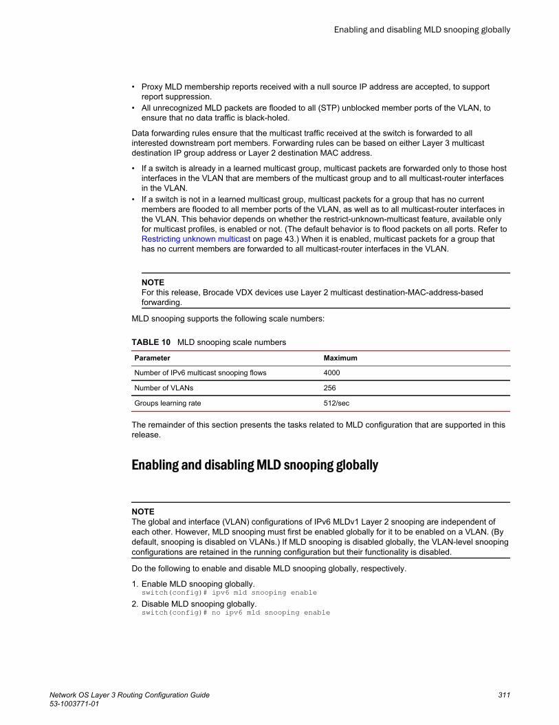
• Proxy MLD membership reports received with a null source IP address are accepted, to supportreport suppression.
• All unrecognized MLD packets are flooded to all (STP) unblocked member ports of the VLAN, toensure that no data traffic is black-holed.
Data forwarding rules ensure that the multicast traffic received at the switch is forwarded to allinterested downstream port members. Forwarding rules can be based on either Layer 3 multicastdestination IP group address or Layer 2 destination MAC address.
• If a switch is already in a learned multicast group, multicast packets are forwarded only to those hostinterfaces in the VLAN that are members of the multicast group and to all multicast-router interfacesin the VLAN.
• If a switch is not in a learned multicast group, multicast packets for a group that has no currentmembers are flooded to all member ports of the VLAN, as well as to all multicast-router interfaces inthe VLAN. This behavior depends on whether the restrict-unknown-multicast feature, available onlyfor multicast profiles, is enabled or not. (The default behavior is to flood packets on all ports. Refer to Restricting unknown multicast on page 43.) When it is enabled, multicast packets for a group thathas no current members are forwarded to all multicast-router interfaces in the VLAN.
NOTEFor this release, Brocade VDX devices use Layer 2 multicast destination-MAC-address-basedforwarding.
MLD snooping supports the following scale numbers:
MLD snooping scale numbersTABLE 10
Parameter Maximum
Number of IPv6 multicast snooping flows 4000
Number of VLANs 256
Groups learning rate 512/sec
The remainder of this section presents the tasks related to MLD configuration that are supported in thisrelease.
Enabling and disabling MLD snooping globally
NOTEThe global and interface (VLAN) configurations of IPv6 MLDv1 Layer 2 snooping are independent ofeach other. However, MLD snooping must first be enabled globally for it to be enabled on a VLAN. (Bydefault, snooping is disabled on VLANs.) If MLD snooping is disabled globally, the VLAN-level snoopingconfigurations are retained in the running configuration but their functionality is disabled.
Do the following to enable and disable MLD snooping globally, respectively.
1. Enable MLD snooping globally.switch(config)# ipv6 mld snooping enable
2. Disable MLD snooping globally.switch(config)# no ipv6 mld snooping enable
Enabling and disabling MLD snooping globally
Network OS Layer 3 Routing Configuration Guide 31153-1003771-01
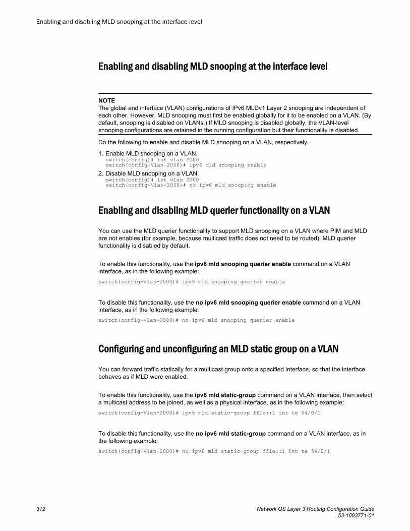
Enabling and disabling MLD snooping at the interface level
NOTEThe global and interface (VLAN) configurations of IPv6 MLDv1 Layer 2 snooping are independent ofeach other. However, MLD snooping must first be enabled globally for it to be enabled on a VLAN. (Bydefault, snooping is disabled on VLANs.) If MLD snooping is disabled globally, the VLAN-levelsnooping configurations are retained in the running configuration but their functionality is disabled.
Do the following to enable and disable MLD snooping on a VLAN, respectively.
1. Enable MLD snooping on a VLAN.switch(config)# int vlan 2000seitch(config-Vlan-2000)# ipv6 mld snooping enable
2. Disable MLD snooping on a VLAN.switch(config)# int vlan 2000seitch(config-Vlan-2000)# no ipv6 mld snooping enable
Enabling and disabling MLD querier functionality on a VLAN
You can use the MLD querier functionality to support MLD snooping on a VLAN where PIM and MLDare not enables (for example, because multicast traffic does not need to be routed). MLD querierfunctionality is disabled by default.
To enable this functionality, use the ipv6 mld snooping querier enable command on a VLANinterface, as in the following example:switch(config-Vlan-2000)# ipv6 mld snooping querier enable
To disable this functionality, use the no ipv6 mld snooping querier enable command on a VLANinterface, as in the following example:switch(config-Vlan-2000)# no ipv6 mld snooping querier enable
Configuring and unconfiguring an MLD static group on a VLAN
You can forward traffic statically for a multicast group onto a specified interface, so that the interfacebehaves as if MLD were enabled.
To enable this functionality, use the ipv6 mld static-group command on a VLAN interface, then selecta multicast address to be joined, as well as a physical interface, as in the following example:switch(config-Vlan-2000)# ipv6 mld static-group ff1e::1 int te 54/0/1
To disable this functionality, use the no ipv6 mld static-group command on a VLAN interface, as inthe following example:switch(config-Vlan-2000)# no ipv6 mld static-group ff1e::1 int te 54/0/1
Enabling and disabling MLD snooping at the interface level
312 Network OS Layer 3 Routing Configuration Guide53-1003771-01
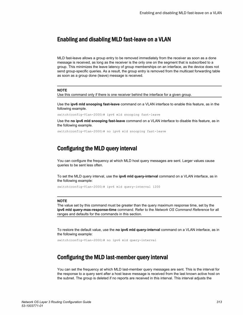
Enabling and disabling MLD fast-leave on a VLAN
MLD fast-leave allows a group entry to be removed immediately from the receiver as soon as a donemessage is received, as long as the receiver is the only one on the segment that is subscribed to agroup. This minimizes the leave latency of group memberships on an interface, as the device does notsend group-specific queries. As a result, the group entry is removed from the multicast forwarding tableas soon as a group done (leave) message is received.
NOTEUse this command only if there is one receiver behind the interface for a given group.
Use the ipv6 mld snooping fast-leave command on a VLAN interface to enable this feature, as in thefollowing example.switch(config-Vlan-2000)# ipv6 mld snooping fast-leaveUse the no ipv6 mld snooping fast-leave command on a VLAN interface to disable this feature, as inthe following example.switch(config-Vlan-2000)# no ipv6 mld snooping fast-leave
Configuring the MLD query interval
You can configure the frequency at which MLD host query messages are sent. Larger values causequeries to be sent less often.
To set the MLD query interval, use the ipv6 mld query-interval command on a VLAN interface, as inthe following example:switch(config-Vlan-2000)# ipv6 mld query-interval 1200
NOTEThe value set by this command must be greater than the query maximum response time, set by theipv6 mld query-max-response-time command. Refer to the Network OS Command Reference for allranges and defaults for the commands in this section.
To restore the default value, use the no ipv6 mld query-interval command on a VLAN interface, as inthe following example:switch(config-Vlan-2000)# no ipv6 mld query-interval
Configuring the MLD last-member query interval
You can set the frequency at which MLD last-member query messages are sent. This is the interval forthe response to a query sent after a host leave message is received from the last known active host onthe subnet. The group is deleted if no reports are received in this interval. This interval adjusts the
Enabling and disabling MLD fast-leave on a VLAN
Network OS Layer 3 Routing Configuration Guide 31353-1003771-01
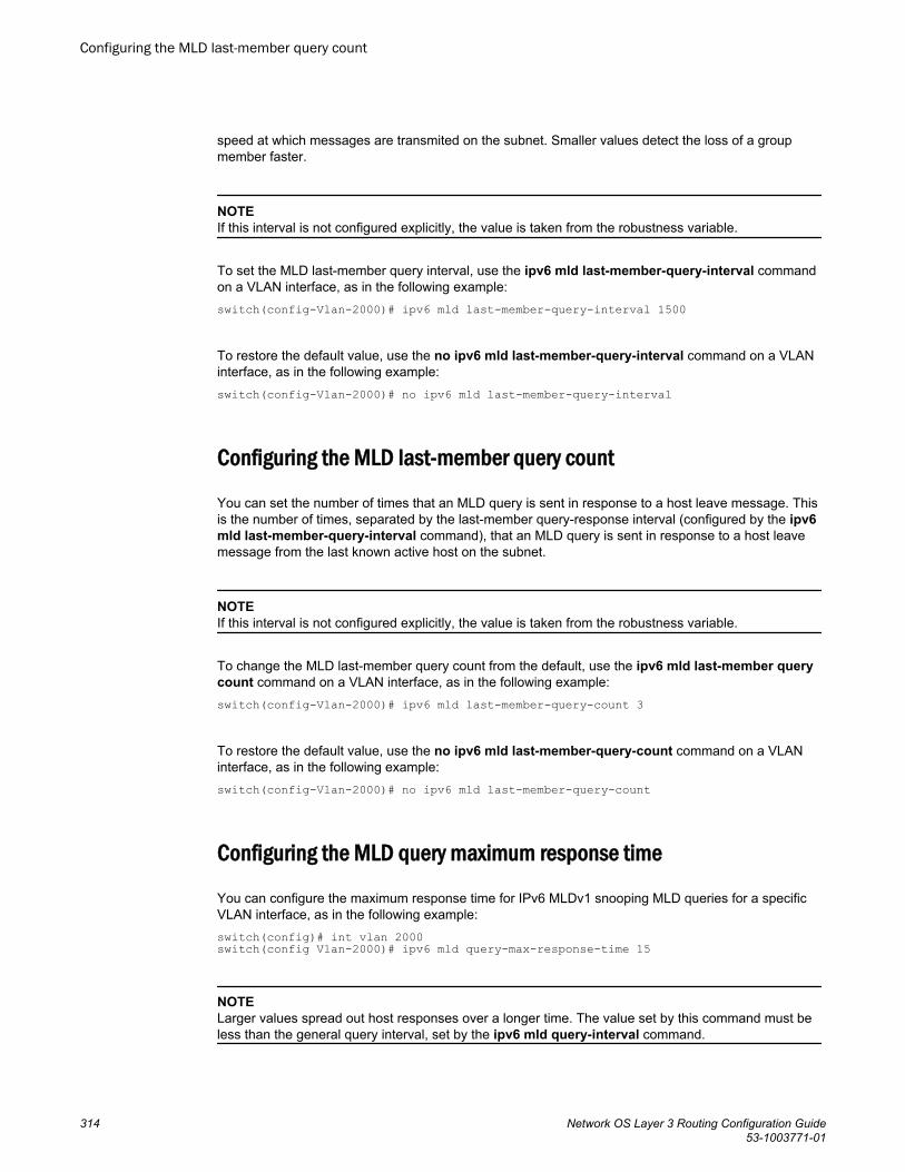
speed at which messages are transmited on the subnet. Smaller values detect the loss of a groupmember faster.
NOTEIf this interval is not configured explicitly, the value is taken from the robustness variable.
To set the MLD last-member query interval, use the ipv6 mld last-member-query-interval commandon a VLAN interface, as in the following example:switch(config-Vlan-2000)# ipv6 mld last-member-query-interval 1500
To restore the default value, use the no ipv6 mld last-member-query-interval command on a VLANinterface, as in the following example:switch(config-Vlan-2000)# no ipv6 mld last-member-query-interval
Configuring the MLD last-member query count
You can set the number of times that an MLD query is sent in response to a host leave message. Thisis the number of times, separated by the last-member query-response interval (configured by the ipv6mld last-member-query-interval command), that an MLD query is sent in response to a host leavemessage from the last known active host on the subnet.
NOTEIf this interval is not configured explicitly, the value is taken from the robustness variable.
To change the MLD last-member query count from the default, use the ipv6 mld last-member querycount command on a VLAN interface, as in the following example:switch(config-Vlan-2000)# ipv6 mld last-member-query-count 3
To restore the default value, use the no ipv6 mld last-member-query-count command on a VLANinterface, as in the following example:switch(config-Vlan-2000)# no ipv6 mld last-member-query-count
Configuring the MLD query maximum response time
You can configure the maximum response time for IPv6 MLDv1 snooping MLD queries for a specificVLAN interface, as in the following example:switch(config)# int vlan 2000switch(config Vlan-2000)# ipv6 mld query-max-response-time 15
NOTELarger values spread out host responses over a longer time. The value set by this command must beless than the general query interval, set by the ipv6 mld query-interval command.
Configuring the MLD last-member query count
314 Network OS Layer 3 Routing Configuration Guide53-1003771-01
To restore the default value, use the no ipv6 mld query-max-response-time command on a VLANinterface, as in the following example:switch(config-Vlan-2000)# no ipv6 mld query-max-response-time
Configuring the MLD snooping robustness variable
A robustness value can be configured to compensate for packet loss in congested networks. This valuedetermines the number of general MLD snooping queries that are sent before a multicast address isaged out for lack of a response. The default is 2.
To change the default robustness variable on a VLAN, use the ipv6 mld snooping robustness-variable command, as in the following example:switch(config-Vlan-2000)# ipv6 mld snooping robustness-variable 7
To restore the default value, use the no ipv6 mld robustness-variable command on a VLAN interface,as in the following example:switch(config-Vlan-2000)# no ipv6 mld robustness-variable
Configuring the MLD startup query count
The IPv6 MLDv1 startup query count is the number of queries that are separated by the startup interval.The default is 1.
Do the following to change the startup-query interval on a VLAN, as in the following example.switch(config-Vlan-2000)# ipv6 mld startup-query-count 2
To restore the default value, use the no ipv6 mld startup-query-count command on a VLAN interface,as in the following example:switch(config-Vlan-2000)# no ipv6 mld startup-query-count
Configuring the MLD startup query interval
You can change the query interval between the general queries that are sent by the querier on startup.The default interval is 1. The querier may be the MLD snooping querier or an external querier.
Do the following to change the startup-query interval on a VLAN, as in the following example.switch(config-Vlan-2000)# ipv6 mld startup-query-interval 2
To restore the default value, use the no ipv6 mld startup-query-interval command on a VLANinterface, as in the following example:switch(config-Vlan-2000)# no ipv6 mld startup-query-interval
Configuring the MLD snooping robustness variable
Network OS Layer 3 Routing Configuration Guide 31553-1003771-01
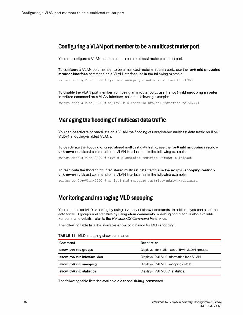
Configuring a VLAN port member to be a multicast router port
You can configure a VLAN port member to be a multicast router (mrouter) port.
To configure a VLAN port member to be a multicast router (mrouter) port., use the ipv6 mld snoopingmrouter interface command on a VLAN interface, as in the following example:switch(config-Vlan-2000)# ipv6 mld snooping mrouter interface te 54/0/1
To disable the VLAN port member from being an mrouter port., use the ipv6 mld snooping mrouterinterface command on a VLAN interface, as in the following example:switch(config-Vlan-2000)# no ipv6 mld snooping mrouter interface te 54/0/1
Managing the flooding of multicast data traffic
You can deactivate or reactivate on a VLAN the flooding of unregistered multicast data traffic on IPv6MLDv1 snooping-enabled VLANs.
To deactivate the flooding of unregistered multicast data traffic, use the ipv6 mld snooping restrict-unknown-multicast command on a VLAN interface, as in the following example:switch(config-Vlan-2000)# ipv6 mld snooping restrict-unknown-multicast
To reactivate the flooding of unregistered multicast data traffic, use the no ipv6 snooping restrict-unknown-multicast command on a VLAN interface, as in the following example:switch(config-Vlan-2000)# no ipv6 mld snooping restrict-unknown-multicast
Monitoring and managing MLD snooping
You can monitor MLD snooping by using a variety of show commands. In addition, you can clear thedata for MLD groups and statistics by using clear commands. A debug command is also available.For command details, refer to the Network OS Command Reference.
The following table lists the available show commands for MLD snooping.
MLD snooping show commandsTABLE 11
Command Description
show ipv6 mld groups Displays information about IPv6 MLDv1 groups.
show ipv6 mld interface vlan Displays IPv6 MLD information for a VLAN.
show ipv6 mld snooping Displays IPv6 MLD snooping details.
show ipv6 mld statistics Displays IPv6 MLDv1 statistics.
The following table lists the available clear and debug commands.
Configuring a VLAN port member to be a multicast router port
316 Network OS Layer 3 Routing Configuration Guide53-1003771-01
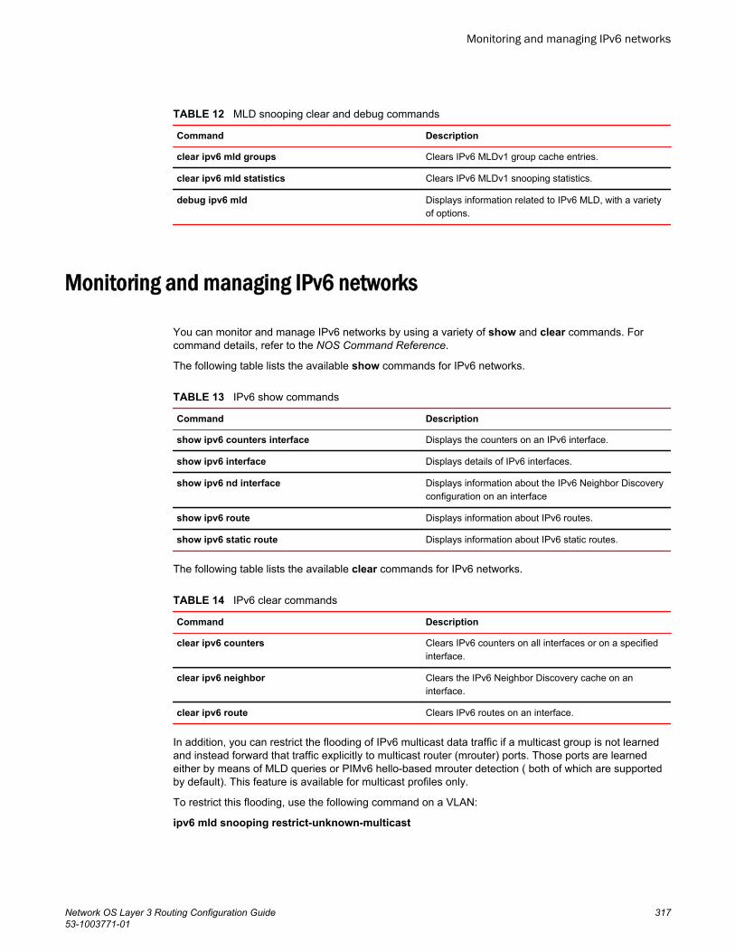
MLD snooping clear and debug commandsTABLE 12
Command Description
clear ipv6 mld groups Clears IPv6 MLDv1 group cache entries.
clear ipv6 mld statistics Clears IPv6 MLDv1 snooping statistics.
debug ipv6 mld Displays information related to IPv6 MLD, with a varietyof options.
Monitoring and managing IPv6 networks
You can monitor and manage IPv6 networks by using a variety of show and clear commands. Forcommand details, refer to the NOS Command Reference.
The following table lists the available show commands for IPv6 networks.
IPv6 show commandsTABLE 13
Command Description
show ipv6 counters interface Displays the counters on an IPv6 interface.
show ipv6 interface Displays details of IPv6 interfaces.
show ipv6 nd interface Displays information about the IPv6 Neighbor Discoveryconfiguration on an interface
show ipv6 route Displays information about IPv6 routes.
show ipv6 static route Displays information about IPv6 static routes.
The following table lists the available clear commands for IPv6 networks.
IPv6 clear commandsTABLE 14
Command Description
clear ipv6 counters Clears IPv6 counters on all interfaces or on a specifiedinterface.
clear ipv6 neighbor Clears the IPv6 Neighbor Discovery cache on aninterface.
clear ipv6 route Clears IPv6 routes on an interface.
In addition, you can restrict the flooding of IPv6 multicast data traffic if a multicast group is not learnedand instead forward that traffic explicitly to multicast router (mrouter) ports. Those ports are learnedeither by means of MLD queries or PIMv6 hello-based mrouter detection ( both of which are supportedby default). This feature is available for multicast profiles only.
To restrict this flooding, use the following command on a VLAN:
ipv6 mld snooping restrict-unknown-multicast
Monitoring and managing IPv6 networks
Network OS Layer 3 Routing Configuration Guide 31753-1003771-01

Monitoring and managing IPv6 networks
318 Network OS Layer 3 Routing Configuration Guide53-1003771-01