connect - deployment guide - broadcom · pdf fileconnect - deployment guide ... create a...
TRANSCRIPT
VMware vSphere 5.5 VXLAN Networking and Emulex OneConnect® OCe14000 Ethernet Adapters
Emulex OneConnect® Network Adapters
CONNECT - DEPLOYMENT GU IDE
Configuring VXLAN with Emulex OneConnect OCe14000 Adapters
2 CONNEC T | VMware vSphere 5.5 VXLAN Networking and Emulex OneConnect® OCe14000 Ethernet Adapters
CONNECT - DEPLOYMENT GU IDE
Table of contents
1.0 Emulex Solution Implementer’s Series . . . . . . . . . . . . . . . . . . . . . . . . . . . . . . . . . . . . . . . . . . . . . . . . . . . . . . . . . . . . . . . . . . . . . . . . . . . . . . . . . . . . . . . . . . . . . . . . . . . . 3
1.1 Executive summary . . . . . . . . . . . . . . . . . . . . . . . . . . . . . . . . . . . . . . . . . . . . . . . . . . . . . . . . . . . . . . . . . . . . . . . . . . . . . . . . . . . . . . . . . . . . . . . . . . . . . . . . . . . . . . . . . . . . . . . . 3
1.2 Introduction . . . . . . . . . . . . . . . . . . . . . . . . . . . . . . . . . . . . . . . . . . . . . . . . . . . . . . . . . . . . . . . . . . . . . . . . . . . . . . . . . . . . . . . . . . . . . . . . . . . . . . . . . . . . . . . . . . . . . . . . . . . . . . . 3
1.3 VXLAN overview . . . . . . . . . . . . . . . . . . . . . . . . . . . . . . . . . . . . . . . . . . . . . . . . . . . . . . . . . . . . . . . . . . . . . . . . . . . . . . . . . . . . . . . . . . . . . . . . . . . . . . . . . . . . . . . . . . . . . . . . . . . 4
2.0 Server hardware requirements . . . . . . . . . . . . . . . . . . . . . . . . . . . . . . . . . . . . . . . . . . . . . . . . . . . . . . . . . . . . . . . . . . . . . . . . . . . . . . . . . . . . . . . . . . . . . . . . . . . . . . . . . . . . 5
2.1 VMware ESX software requirements . . . . . . . . . . . . . . . . . . . . . . . . . . . . . . . . . . . . . . . . . . . . . . . . . . . . . . . . . . . . . . . . . . . . . . . . . . . . . . . . . . . . . . . . . . . . . . . . . . . . . . 5
2.2 Emulex OCe14000 Network Adapter requirements. . . . . . . . . . . . . . . . . . . . . . . . . . . . . . . . . . . . . . . . . . . . . . . . . . . . . . . . . . . . . . . . . . . . . . . . . . . . . . . . . . . . . . . 5
2.3 Additional requirements . . . . . . . . . . . . . . . . . . . . . . . . . . . . . . . . . . . . . . . . . . . . . . . . . . . . . . . . . . . . . . . . . . . . . . . . . . . . . . . . . . . . . . . . . . . . . . . . . . . . . . . . . . . . . . . . . . 5
3.0 Deploying Emulex OneConnect Network Adapters in ESXi 5.5 . . . . . . . . . . . . . . . . . . . . . . . . . . . . . . . . . . . . . . . . . . . . . . . . . . . . . . . . . . . . . . . . . . . . . . . . . . . . 6
3.1 VXLAN prerequisites . . . . . . . . . . . . . . . . . . . . . . . . . . . . . . . . . . . . . . . . . . . . . . . . . . . . . . . . . . . . . . . . . . . . . . . . . . . . . . . . . . . . . . . . . . . . . . . . . . . . . . . . . . . . . . . . . . . . . . 6
4.0 Create cluster . . . . . . . . . . . . . . . . . . . . . . . . . . . . . . . . . . . . . . . . . . . . . . . . . . . . . . . . . . . . . . . . . . . . . . . . . . . . . . . . . . . . . . . . . . . . . . . . . . . . . . . . . . . . . . . . . . . . . . . . . . . . . 7
5.0 Create VDS . . . . . . . . . . . . . . . . . . . . . . . . . . . . . . . . . . . . . . . . . . . . . . . . . . . . . . . . . . . . . . . . . . . . . . . . . . . . . . . . . . . . . . . . . . . . . . . . . . . . . . . . . . . . . . . . . . . . . . . . . . . . . . .10
6.0 Deploying VMware vShield Manager appliance . . . . . . . . . . . . . . . . . . . . . . . . . . . . . . . . . . . . . . . . . . . . . . . . . . . . . . . . . . . . . . . . . . . . . . . . . . . . . . . . . . . . . . . . . .13
7.0 Configure VXLAN networking . . . . . . . . . . . . . . . . . . . . . . . . . . . . . . . . . . . . . . . . . . . . . . . . . . . . . . . . . . . . . . . . . . . . . . . . . . . . . . . . . . . . . . . . . . . . . . . . . . . . . . . . . . . .23
8.0 Adding physical adapters for VXLAN networking . . . . . . . . . . . . . . . . . . . . . . . . . . . . . . . . . . . . . . . . . . . . . . . . . . . . . . . . . . . . . . . . . . . . . . . . . . . . . . . . . . . . . . . .31
9.0 Verifying OCe14000 Network Adapter offload enabled/disabled . . . . . . . . . . . . . . . . . . . . . . . . . . . . . . . . . . . . . . . . . . . . . . . . . . . . . . . . . . . . . . . . . . . . . . . .34
10.0 Conclusion . . . . . . . . . . . . . . . . . . . . . . . . . . . . . . . . . . . . . . . . . . . . . . . . . . . . . . . . . . . . . . . . . . . . . . . . . . . . . . . . . . . . . . . . . . . . . . . . . . . . . . . . . . . . . . . . . . . . . . . . . . . . . .36
11.0 References . . . . . . . . . . . . . . . . . . . . . . . . . . . . . . . . . . . . . . . . . . . . . . . . . . . . . . . . . . . . . . . . . . . . . . . . . . . . . . . . . . . . . . . . . . . . . . . . . . . . . . . . . . . . . . . . . . . . . . . . . . . . . . .46
3 CONNEC T | VMware vSphere 5.5 VXLAN Networking and Emulex OneConnect® OCe14000 Ethernet Adapters
CONNECT - DEPLOYMENT GU IDE
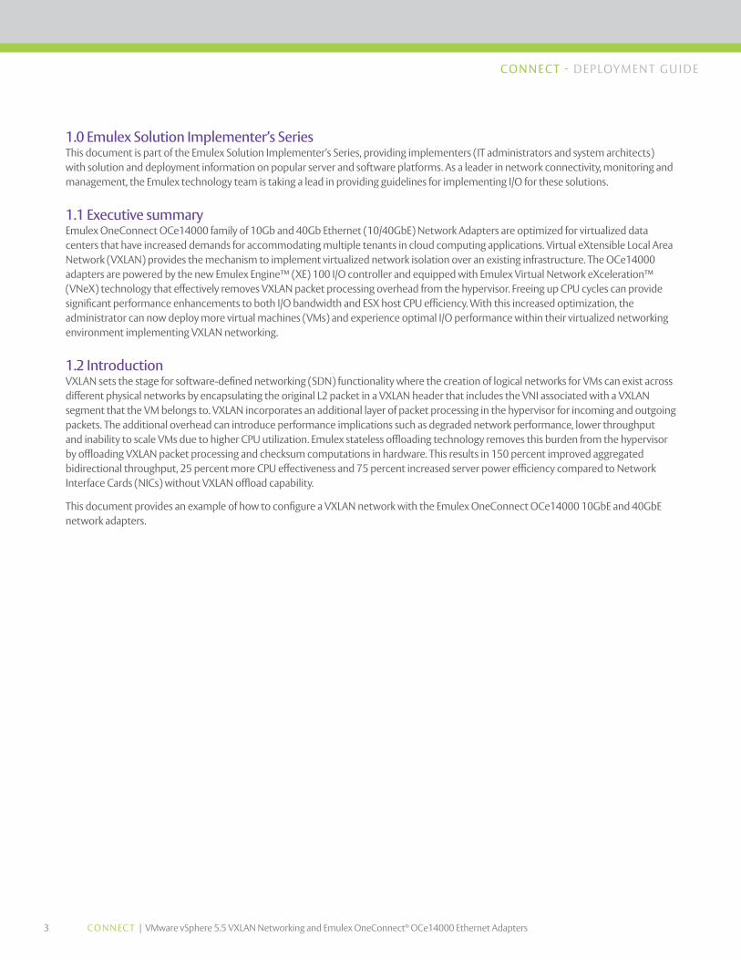
1.0 Emulex Solution Implementer’s Series This document is part of the Emulex Solution Implementer’s Series, providing implementers (IT administrators and system architects) with solution and deployment information on popular server and software platforms. As a leader in network connectivity, monitoring and management, the Emulex technology team is taking a lead in providing guidelines for implementing I/O for these solutions.
1.1 Executive summary Emulex OneConnect OCe14000 family of 10Gb and 40Gb Ethernet (10/40GbE) Network Adapters are optimized for virtualized data centers that have increased demands for accommodating multiple tenants in cloud computing applications. Virtual eXtensible Local Area Network (VXLAN) provides the mechanism to implement virtualized network isolation over an existing infrastructure. The OCe14000 adapters are powered by the new Emulex Engine™ (XE) 100 I/O controller and equipped with Emulex Virtual Network eXceleration™ (VNeX) technology that effectively removes VXLAN packet processing overhead from the hypervisor. Freeing up CPU cycles can provide significant performance enhancements to both I/O bandwidth and ESX host CPU efficiency. With this increased optimization, the administrator can now deploy more virtual machines (VMs) and experience optimal I/O performance within their virtualized networking environment implementing VXLAN networking.
1.2 Introduction VXLAN sets the stage for software-defined networking (SDN) functionality where the creation of logical networks for VMs can exist across different physical networks by encapsulating the original L2 packet in a VXLAN header that includes the VNI associated with a VXLAN segment that the VM belongs to. VXLAN incorporates an additional layer of packet processing in the hypervisor for incoming and outgoing packets. The additional overhead can introduce performance implications such as degraded network performance, lower throughput and inability to scale VMs due to higher CPU utilization. Emulex stateless offloading technology removes this burden from the hypervisor by offloading VXLAN packet processing and checksum computations in hardware. This results in 150 percent improved aggregated bidirectional throughput, 25 percent more CPU effectiveness and 75 percent increased server power efficiency compared to Network Interface Cards (NICs) without VXLAN offload capability.
This document provides an example of how to configure a VXLAN network with the Emulex OneConnect OCe14000 10GbE and 40GbE network adapters.

4 CONNEC T | VMware vSphere 5.5 VXLAN Networking and Emulex OneConnect® OCe14000 Ethernet Adapters
CONNECT - DEPLOYMENT GU IDE
1.3 VMware VXLAN overview VXLAN uses MAC Address-in-User Datagram Protocol (MAC-in-UDP) encapsulation whereby VMs can be deployed on any ESX host while being decoupled from the underlying physical network. VXLAN uses a 24-bit identifier allowing a single network to support up to 16 million LAN segments surpassing the IEEE 802.1Q VLAN specification of 4,094 VLANs. This capability can be best utilized in cloud computing by providing complete network isolation for multiple tenants while utilizing common physical infrastructure. Figure 2 below depicts a basic VXLAN configuration with multiple VXLANs between ESX Host A and B extended across a L3 network. When a packet is sent from a VM in host A to a VM in host B, the entire packet is encapsulated in a VXLAN header and traverses over the physical network. When the VXLAN packet reaches ESX Host B, the VXLAN header is removed and the packet is received by the recipient VM with the Inner MAC Destination Address (DA). A VXLAN Tunnel Endpoint (VTEP) is configured on each participating host and assigned with a unique IP address and responsible for VXLAN data path processing, maintaining forwarding tables and encapsulation/de-encapsulation of VXLAN packets. A VTEP consists of a vmkernel module, vmknic virtual adapter module and VXLAN port group module.
Figure 1. VXLAN packet format.
Figure 2. Basic VXLAN deployment with four virtual wires for network isolation.
5 CONNEC T | VMware vSphere 5.5 VXLAN Networking and Emulex OneConnect® OCe14000 Ethernet Adapters
CONNECT - DEPLOYMENT GU IDE
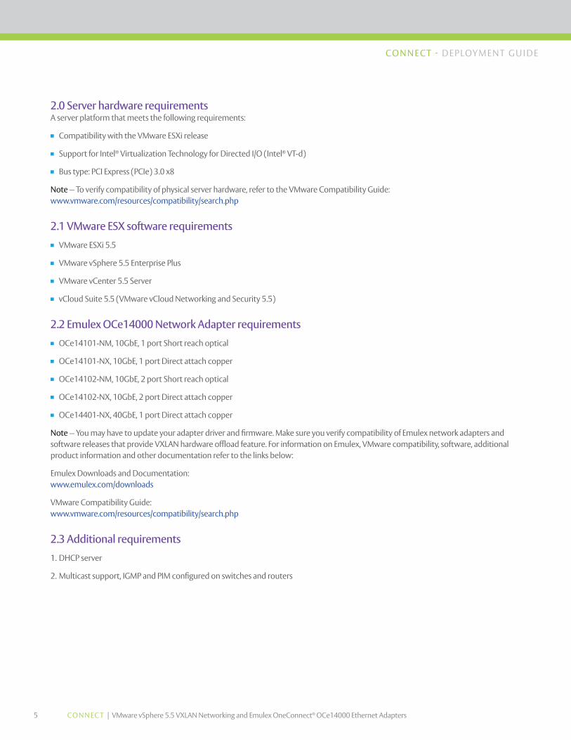
2.0 Server hardware requirements A server platform that meets the following requirements:
n Compatibility with the VMware ESXi release
n Support for Intel® Virtualization Technology for Directed I/O (Intel® VT-d)
n Bus type: PCI Express (PCIe) 3.0 x8
Note—To verify compatibility of physical server hardware, refer to the VMware Compatibility Guide: www.vmware.com/resources/compatibility/search.php
2.1 VMware ESX software requirements
n VMware ESXi 5.5
n VMware vSphere 5.5 Enterprise Plus
n VMware vCenter 5.5 Server
n vCloud Suite 5.5 (VMware vCloud Networking and Security 5.5)
2.2 Emulex OCe14000 Network Adapter requirements
n OCe14101-NM, 10GbE, 1 port Short reach optical
n OCe14101-NX, 10GbE, 1 port Direct attach copper
n OCe14102-NM, 10GbE, 2 port Short reach optical
n OCe14102-NX, 10GbE, 2 port Direct attach copper
n OCe14401-NX, 40GbE, 1 port Direct attach copper
Note—You may have to update your adapter driver and firmware. Make sure you verify compatibility of Emulex network adapters and software releases that provide VXLAN hardware offload feature. For information on Emulex, VMware compatibility, software, additional product information and other documentation refer to the links below:
Emulex Downloads and Documentation: www.emulex.com/downloads
VMware Compatibility Guide: www.vmware.com/resources/compatibility/search.php
2.3 Additional requirements
1. DHCP server
2. Multicast support, IGMP and PIM configured on switches and routers
6 CONNEC T | VMware vSphere 5.5 VXLAN Networking and Emulex OneConnect® OCe14000 Ethernet Adapters
CONNECT - DEPLOYMENT GU IDE
3.0 Deploying Emulex OneConnect Adapters in ESXi 5.5 hosts
ESX Host and System Enablement
1. Install the OneConnect Ethernet adapter in an available PCIe 3.0 x8 slot
2. Power up the server
3. Enter the server’s BIOS setup and make sure the virtualization technology, Intel® VT-d, is enabled on the server
4. Install VMware ESXi 5.5i Enterprise Plus on the server
5. Install VMware vCenter Server 5.5
6. Deploy Virtual Machines
7. If required, install latest version of Emulex driver and firmware
Note—For details on installing VMware vSphere 5.5 and other components refer to VMWare documentation: http://pubs.vmware.com/vsphere-55/index.jsp#com.vmware.vsphere.install.doc/GUID-BC044F6C-4733-4413-87E6-A00D3BDEDE58.html
3.1 VXLAN prerequisites You can configure your environment using VMware vSphere Client or vSphere Web Client. During the initial VXLAN installation, you will have to login and configure settings in vShield manager. It is highly recommended to deploy a DHCP server in your physical network in so that your ESX host VTEP interfaces can request and receive an IP address. As a prerequisite to configuring VXLAN networking, you must first do the following:
1. Create Clusters
2. Add ESX hosts to Clusters
3. Create a VMware vSphere Distributed Switch (VDS)
4. Configure VMware vShield Manager Appliance
7 CONNEC T | VMware vSphere 5.5 VXLAN Networking and Emulex OneConnect® OCe14000 Ethernet Adapters
CONNECT - DEPLOYMENT GU IDE
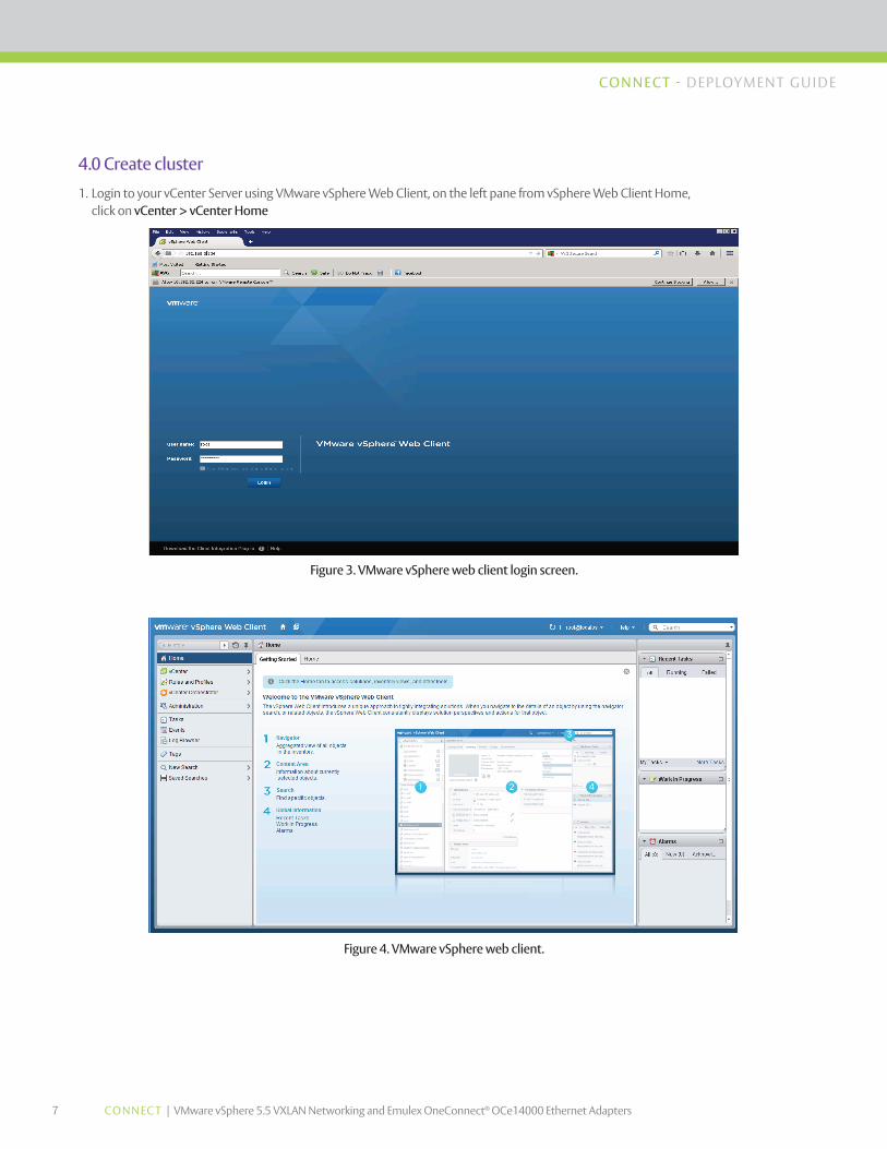
4.0 Create cluster
1. Login to your vCenter Server using VMware vSphere Web Client, on the left pane from vSphere Web Client Home, click on vCenter > vCenter Home
Figure 4. VMware vSphere web client.
Figure 3. VMware vSphere web client login screen.
8 CONNEC T | VMware vSphere 5.5 VXLAN Networking and Emulex OneConnect® OCe14000 Ethernet Adapters
CONNECT - DEPLOYMENT GU IDE
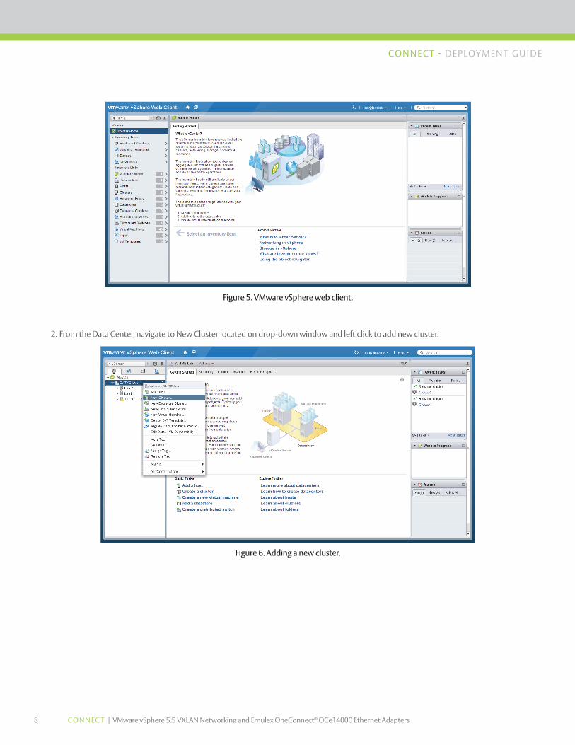
2. From the Data Center, navigate to New Cluster located on drop-down window and left click to add new cluster.
Figure 5. VMware vSphere web client.
Figure 6. Adding a new cluster.
9 CONNEC T | VMware vSphere 5.5 VXLAN Networking and Emulex OneConnect® OCe14000 Ethernet Adapters
CONNECT - DEPLOYMENT GU IDE
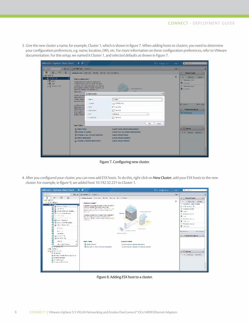
3. Give the new cluster a name, for example, Cluster 1, which is shown in figure 7. When adding hosts to clusters, you need to determine your configuration preferences, e.g. name, location, DRS, etc. For more information on these configuration preferences, refer to VMware documentation. For this setup, we named it Cluster 1, and selected defaults as shown in Figure 7.
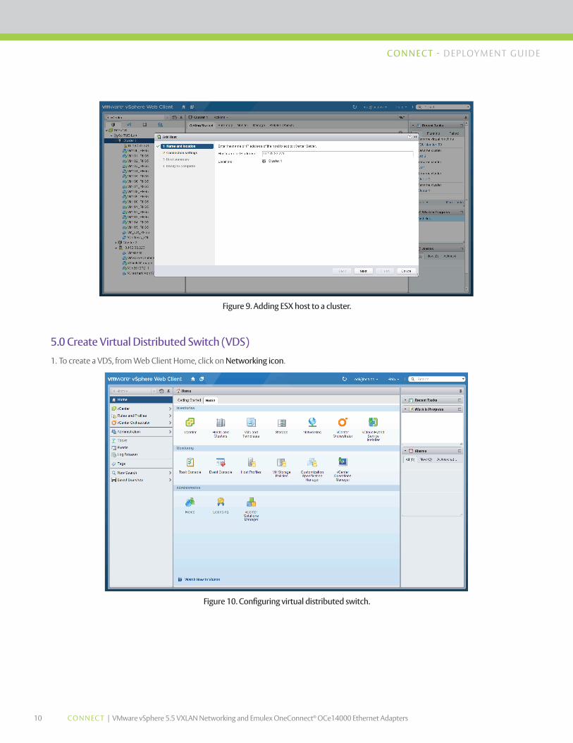
4. After you configured your cluster, you can now add ESX hosts. To do this, right click on New Cluster, add your ESX hosts to the new cluster. For example, in figure 9, we added host 10.192.32.221 to Cluster 1.
Figure 7. Configuring new cluster.
Figure 8. Adding ESX host to a cluster.
10 CONNEC T | VMware vSphere 5.5 VXLAN Networking and Emulex OneConnect® OCe14000 Ethernet Adapters
CONNECT - DEPLOYMENT GU IDE
Figure 9. Adding ESX host to a cluster.
Figure 10. Configuring virtual distributed switch.
5.0 Create Virtual Distributed Switch (VDS)
1. To create a VDS, from Web Client Home, click on Networking icon.
11 CONNEC T | VMware vSphere 5.5 VXLAN Networking and Emulex OneConnect® OCe14000 Ethernet Adapters
CONNECT - DEPLOYMENT GU IDE
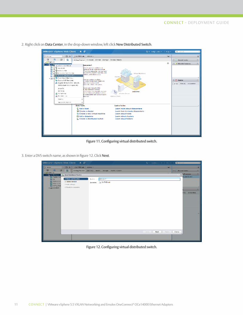
2. Right click on Data Center, in the drop-down window, left click New Distributed Switch.
Figure 11. Configuring virtual distributed switch.
Figure 12. Configuring virtual distributed switch.
3. Enter a DVS switch name, as shown in figure 12. Click Next.
12 CONNEC T | VMware vSphere 5.5 VXLAN Networking and Emulex OneConnect® OCe14000 Ethernet Adapters
CONNECT - DEPLOYMENT GU IDE
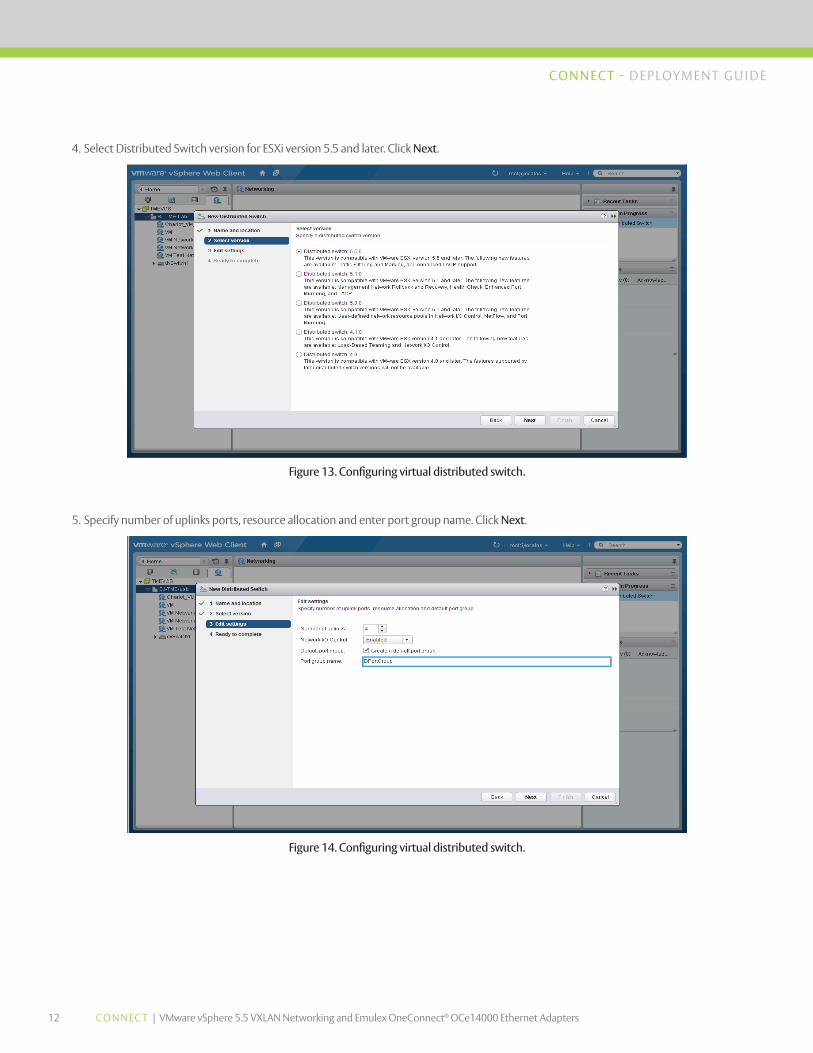
4. Select Distributed Switch version for ESXi version 5.5 and later. Click Next.
Figure 13. Configuring virtual distributed switch.
Figure 14. Configuring virtual distributed switch.
5. Specify number of uplinks ports, resource allocation and enter port group name. Click Next.
13 CONNEC T | VMware vSphere 5.5 VXLAN Networking and Emulex OneConnect® OCe14000 Ethernet Adapters
CONNECT - DEPLOYMENT GU IDE
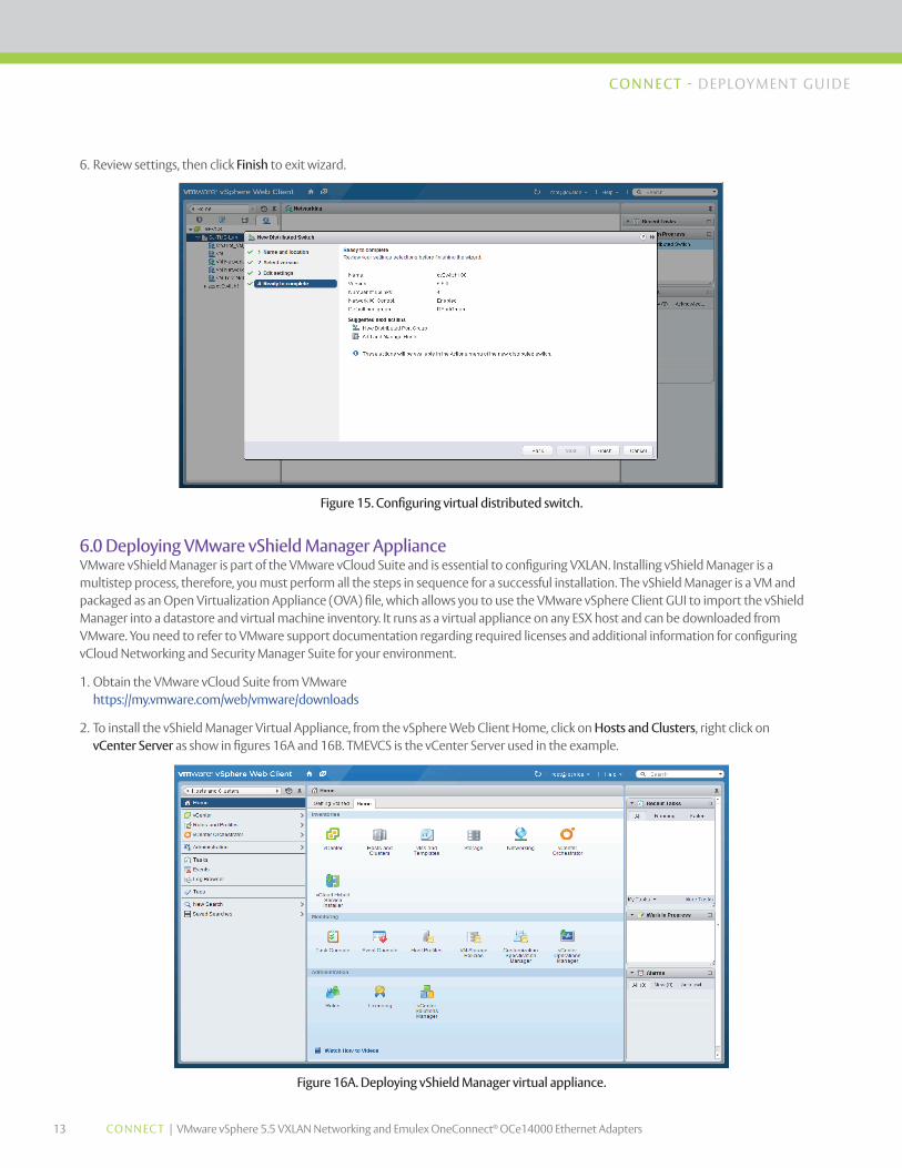
6. Review settings, then click Finish to exit wizard.
Figure 15. Configuring virtual distributed switch.
Figure 16A. Deploying vShield Manager virtual appliance.
6.0 Deploying VMware vShield Manager Appliance VMware vShield Manager is part of the VMware vCloud Suite and is essential to configuring VXLAN. Installing vShield Manager is a multistep process, therefore, you must perform all the steps in sequence for a successful installation. The vShield Manager is a VM and packaged as an Open Virtualization Appliance (OVA) file, which allows you to use the VMware vSphere Client GUI to import the vShield Manager into a datastore and virtual machine inventory. It runs as a virtual appliance on any ESX host and can be downloaded from VMware. You need to refer to VMware support documentation regarding required licenses and additional information for configuring vCloud Networking and Security Manager Suite for your environment.
1. Obtain the VMware vCloud Suite from VMware https://my.vmware.com/web/vmware/downloads
2. To install the vShield Manager Virtual Appliance, from the vSphere Web Client Home, click on Hosts and Clusters, right click on vCenter Server as show in figures 16A and 16B. TMEVCS is the vCenter Server used in the example.
14 CONNEC T | VMware vSphere 5.5 VXLAN Networking and Emulex OneConnect® OCe14000 Ethernet Adapters
CONNECT - DEPLOYMENT GU IDE
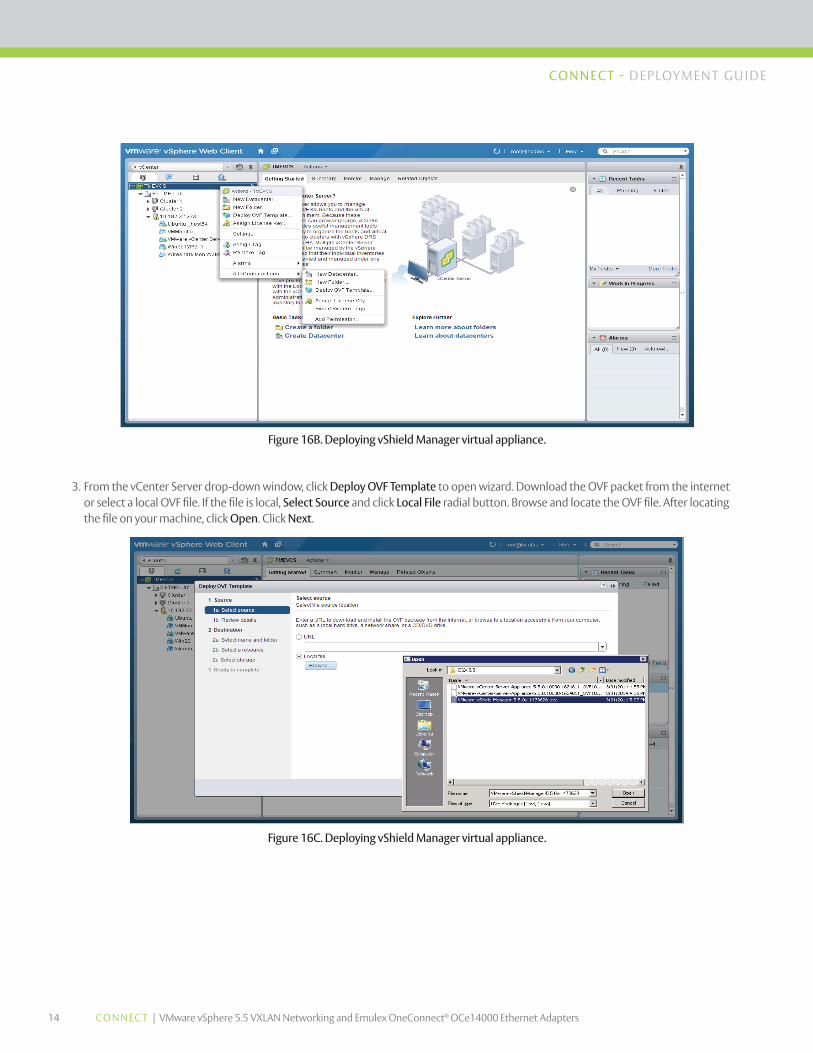
3. From the vCenter Server drop-down window, click Deploy OVF Template to open wizard. Download the OVF packet from the internet or select a local OVF file. If the file is local, Select Source and click Local File radial button. Browse and locate the OVF file. After locating the file on your machine, click Open. Click Next.
Figure 16B. Deploying vShield Manager virtual appliance.
Figure 16C. Deploying vShield Manager virtual appliance.
15 CONNEC T | VMware vSphere 5.5 VXLAN Networking and Emulex OneConnect® OCe14000 Ethernet Adapters
CONNECT - DEPLOYMENT GU IDE
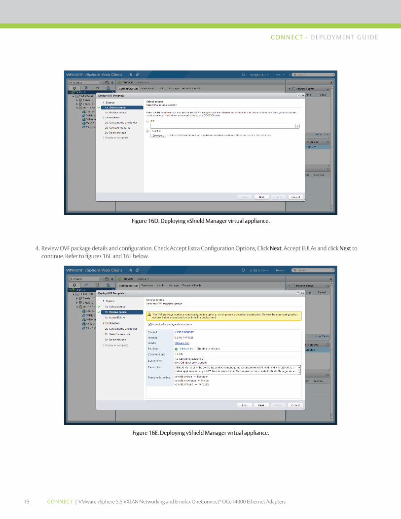
4. Review OVF package details and configuration. Check Accept Extra Configuration Options, Click Next. Accept EULAs and click Next to continue. Refer to figures 16E and 16F below.
Figure 16D. Deploying vShield Manager virtual appliance.
Figure 16E. Deploying vShield Manager virtual appliance.

16 CONNEC T | VMware vSphere 5.5 VXLAN Networking and Emulex OneConnect® OCe14000 Ethernet Adapters
CONNECT - DEPLOYMENT GU IDE
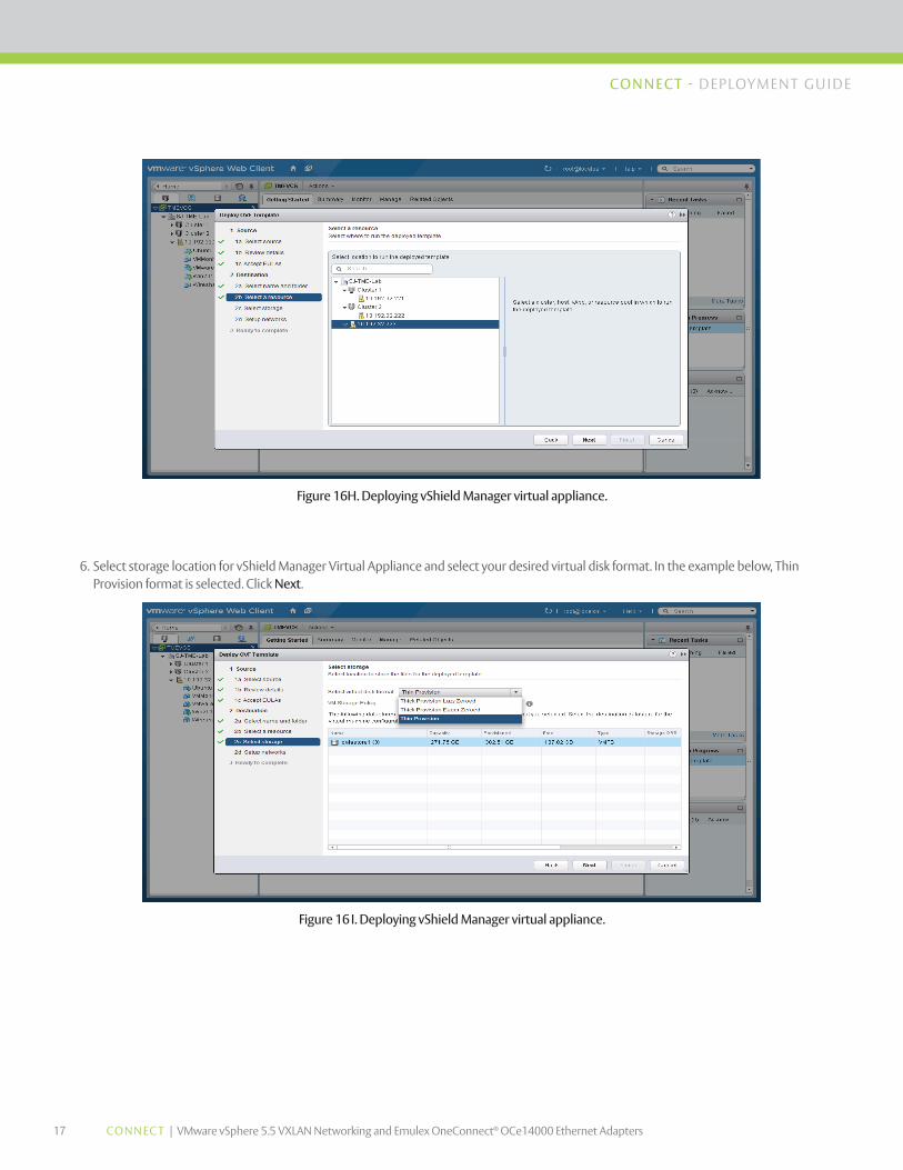
5. Specify a unique name for your vShield Manager appliance and select folder or data center location where you would like for it to reside. In figure 16H below we selected ESX Host 10.192.32.223 located in SJ-TME-Lab data center.
Figure 16F. Deploying vShield Manager virtual appliance.
Figure 16G. Deploying vShield Manager virtual appliance.
17 CONNEC T | VMware vSphere 5.5 VXLAN Networking and Emulex OneConnect® OCe14000 Ethernet Adapters
CONNECT - DEPLOYMENT GU IDE
6. Select storage location for vShield Manager Virtual Appliance and select your desired virtual disk format. In the example below, Thin Provision format is selected. Click Next.
Figure 16H. Deploying vShield Manager virtual appliance.
Figure 16I. Deploying vShield Manager virtual appliance.
18 CONNEC T | VMware vSphere 5.5 VXLAN Networking and Emulex OneConnect® OCe14000 Ethernet Adapters
CONNECT - DEPLOYMENT GU IDE
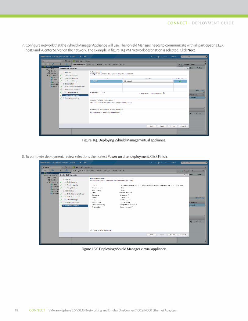
7. Configure network that the vShield Manager Appliance will use. The vShield Manager needs to communicate with all participating ESX hosts and vCenter Server on the network. The example in figure 16J VM Network destination is selected. Click Next.
Figure 16J. Deploying vShield Manager virtual appliance.
Figure 16K. Deploying vShield Manager virtual appliance.
8. To complete deployment, review selections then select Power on after deployment. Click Finish.

19 CONNEC T | VMware vSphere 5.5 VXLAN Networking and Emulex OneConnect® OCe14000 Ethernet Adapters
CONNECT - DEPLOYMENT GU IDE
9. Check status of your vShield Manager OVF deployment under Recent Tasks located on the right pane in vSphere Web Client. Proceed to the next step after vShield Manager has completed OVF deployment.
Figure 16L. Deploying vShield Manager virtual appliance.
Figure 17. Configuring vShield Manager virtual appliance.
10. From vSphere Web Client, right click vShield Manager Appliance. In the drop-down window select Open Console.

20 CONNEC T | VMware vSphere 5.5 VXLAN Networking and Emulex OneConnect® OCe14000 Ethernet Adapters
CONNECT - DEPLOYMENT GU IDE
12. Login to the vShield Manager Appliance using the following default credentials: Login: admin, Password: default.
13. Type enable, re-enter the default password.
14. During the initial setup, you will have to log out of the vShield Manager Appliance and log back in before you can proceed with setup. You will have to allow time for the vShield Manager to complete initializing.
15. Once you log back into vShield Manager, type enable and enter your Password. Type Setup to configure IP address, subnet mask, gateway, primary and secondary DNS. If available, enter your DNS domain search list. If no DNS domain list is available, only fully qualified hostnames will be resolved. Refer to figure 18 below.
16. Select “y” to save the new configuration. Logout and login back again to complete setup.
Figure 18. Configuring vShield Manager virtual appliance.
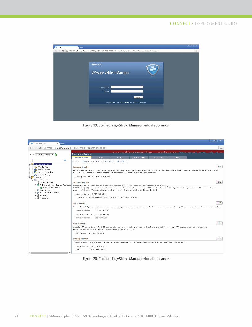
17. Open an internet browser and enter the vShield Manager Appliance URL/IP address you configured above. Login into the vShield Manager Appliance using the same default credentials: Login: admin, Password: default.
18. From Settings & Report folder located on left pane, click Configuration tab to configure Lookup Service URL, vCenter Server IP address, DNS servers IP address, NTP server and Syslog Server IP addresses. An example is illustrated in figure 20 below.
21 CONNEC T | VMware vSphere 5.5 VXLAN Networking and Emulex OneConnect® OCe14000 Ethernet Adapters
CONNECT - DEPLOYMENT GU IDE
Figure 19. Configuring vShield Manager virtual appliance.
Figure 20. Configuring vShield Manager virtual appliance.
22 CONNEC T | VMware vSphere 5.5 VXLAN Networking and Emulex OneConnect® OCe14000 Ethernet Adapters
CONNECT - DEPLOYMENT GU IDE
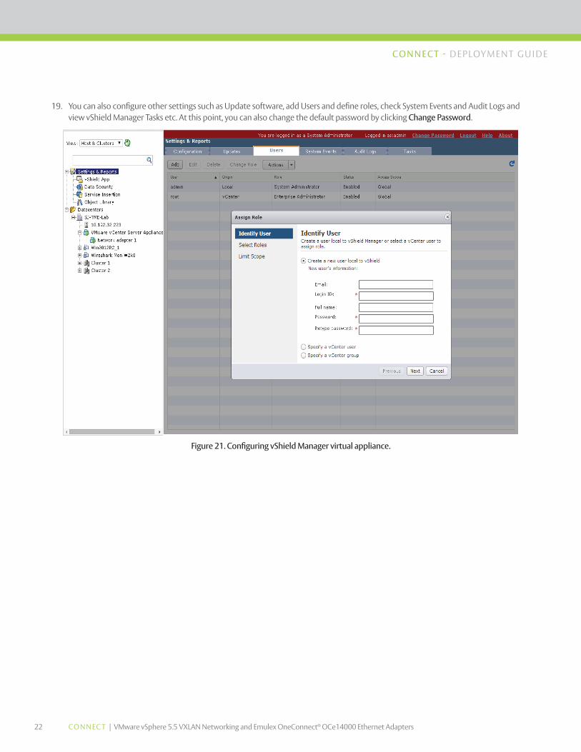
19. You can also configure other settings such as Update software, add Users and define roles, check System Events and Audit Logs and view vShield Manager Tasks etc. At this point, you can also change the default password by clicking Change Password.
Figure 21. Configuring vShield Manager virtual appliance.
23 CONNEC T | VMware vSphere 5.5 VXLAN Networking and Emulex OneConnect® OCe14000 Ethernet Adapters
CONNECT - DEPLOYMENT GU IDE
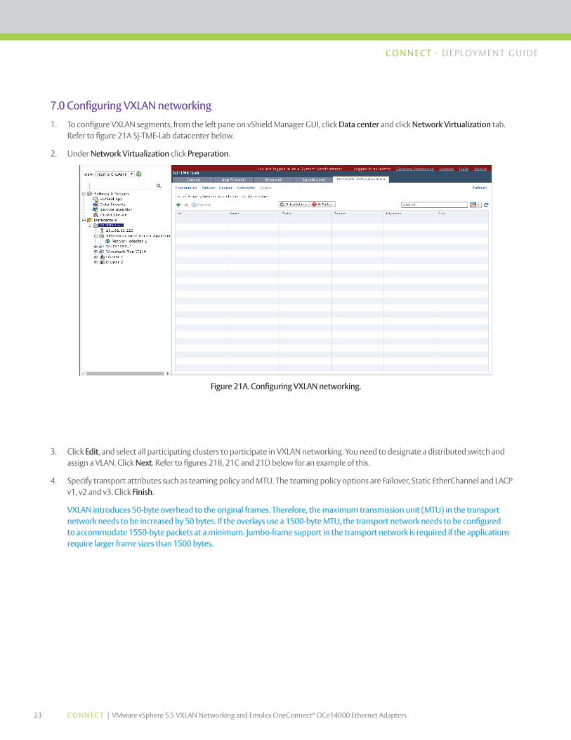
7.0 Configuring VXLAN networking
1. To configure VXLAN segments, from the left pane on vShield Manager GUI, click Data center and click Network Virtualization tab. Refer to figure 21A SJ-TME-Lab datacenter below.
2. Under Network Virtualization click Preparation.
Figure 21A. Configuring VXLAN networking.
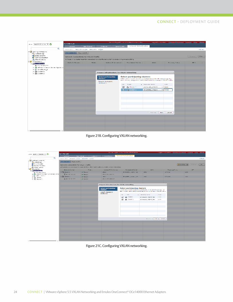
3. Click Edit, and select all participating clusters to participate in VXLAN networking. You need to designate a distributed switch and assign a VLAN. Click Next. Refer to figures 21B, 21C and 21D below for an example of this.
4. Specify transport attributes such as teaming policy and MTU. The teaming policy options are Failover, Static EtherChannel and LACP v1, v2 and v3. Click Finish.
VXLAN introduces 50-byte overhead to the original frames. Therefore, the maximum transmission unit (MTU) in the transport network needs to be increased by 50 bytes. If the overlays use a 1500-byte MTU, the transport network needs to be configured to accommodate 1550-byte packets at a minimum. Jumbo-frame support in the transport network is required if the applications require larger frame sizes than 1500 bytes.
24 CONNEC T | VMware vSphere 5.5 VXLAN Networking and Emulex OneConnect® OCe14000 Ethernet Adapters
CONNECT - DEPLOYMENT GU IDE
Figure 21B. Configuring VXLAN networking.
Figure 21C. Configuring VXLAN networking.
25 CONNEC T | VMware vSphere 5.5 VXLAN Networking and Emulex OneConnect® OCe14000 Ethernet Adapters
CONNECT - DEPLOYMENT GU IDE
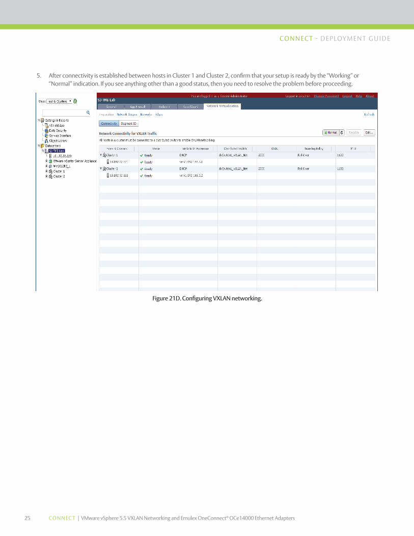
5. After connectivity is established between hosts in Cluster 1 and Cluster 2, confirm that your setup is ready by the “Working” or “Normal” indication. If you see anything other than a good status, then you need to resolve the problem before proceeding.
Figure 21D. Configuring VXLAN networking.
26 CONNEC T | VMware vSphere 5.5 VXLAN Networking and Emulex OneConnect® OCe14000 Ethernet Adapters
CONNECT - DEPLOYMENT GU IDE
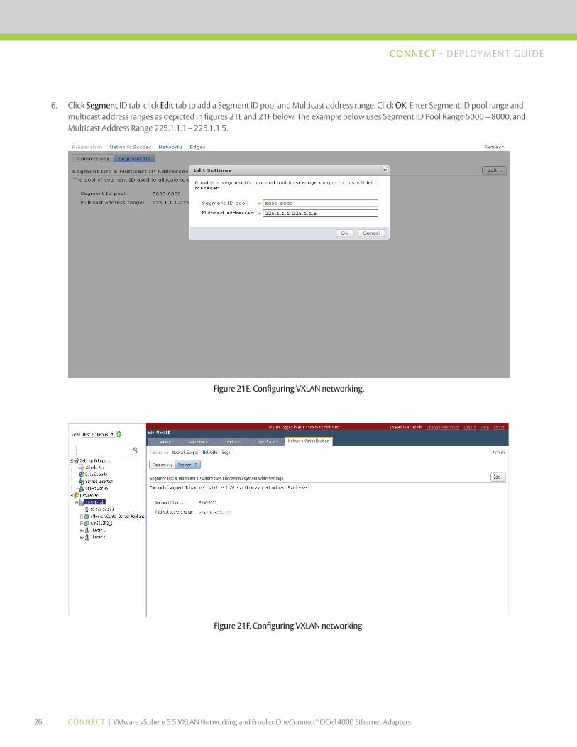
6. Click Segment ID tab, click Edit tab to add a Segment ID pool and Multicast address range. Click OK. Enter Segment ID pool range and multicast address ranges as depicted in figures 21E and 21F below. The example below uses Segment ID Pool Range 5000 – 8000, and Multicast Address Range 225.1.1.1 – 225.1.1.5.
Figure 21E. Configuring VXLAN networking.
Figure 21F. Configuring VXLAN networking.
27 CONNEC T | VMware vSphere 5.5 VXLAN Networking and Emulex OneConnect® OCe14000 Ethernet Adapters
CONNECT - DEPLOYMENT GU IDE
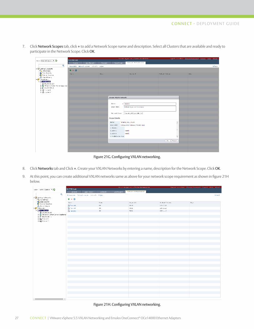
7. Click Network Scopes tab, click + to add a Network Scope name and description. Select all Clusters that are available and ready to participate in the Network Scope. Click OK.
Figure 21G. Configuring VXLAN networking.
Figure 21H. Configuring VXLAN networking.
8. Click Networks tab and Click +. Create your VXLAN Networks by entering a name, description for the Network Scope. Click OK.
9. At this point, you can create additional VXLAN networks same as above for your network scope requirement as shown in figure 21H below.
28 CONNEC T | VMware vSphere 5.5 VXLAN Networking and Emulex OneConnect® OCe14000 Ethernet Adapters
CONNECT - DEPLOYMENT GU IDE
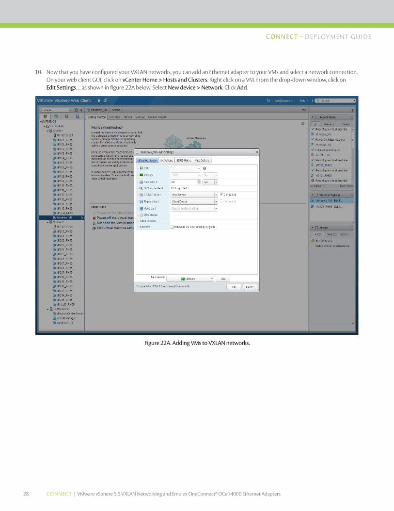
10. Now that you have configured your VXLAN networks, you can add an Ethernet adapter to your VMs and select a network connection. On your web client GUI, click on vCenter Home > Hosts and Clusters. Right click on a VM. From the drop-down window, click on Edit Settings… as shown in figure 22A below. Select New device > Network. Click Add.
Figure 22A. Adding VMs to VXLAN networks.
29 CONNEC T | VMware vSphere 5.5 VXLAN Networking and Emulex OneConnect® OCe14000 Ethernet Adapters
CONNECT - DEPLOYMENT GU IDE
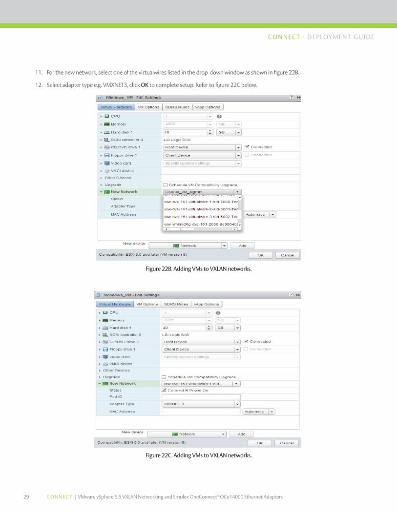
11. For the new network, select one of the virtualwires listed in the drop-down window as shown in figure 22B.
12. Select adapter type e.g. VMXNET3, click OK to complete setup. Refer to figure 22C below.
Figure 22B. Adding VMs to VXLAN networks.
Figure 22C. Adding VMs to VXLAN networks.
30 CONNEC T | VMware vSphere 5.5 VXLAN Networking and Emulex OneConnect® OCe14000 Ethernet Adapters
CONNECT - DEPLOYMENT GU IDE
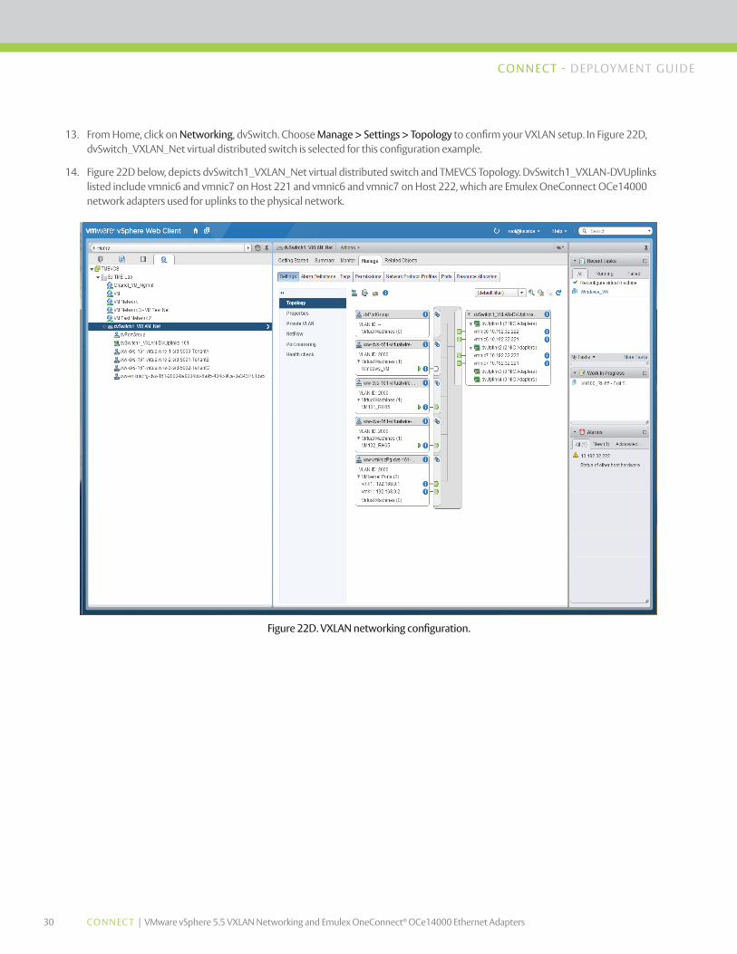
13. From Home, click on Networking, dvSwitch. Choose Manage > Settings > Topology to confirm your VXLAN setup. In Figure 22D, dvSwitch_VXLAN_Net virtual distributed switch is selected for this configuration example.
14. Figure 22D below, depicts dvSwitch1_VXLAN_Net virtual distributed switch and TMEVCS Topology. DvSwitch1_VXLAN-DVUplinks listed include vmnic6 and vmnic7 on Host 221 and vmnic6 and vmnic7 on Host 222, which are Emulex OneConnect OCe14000 network adapters used for uplinks to the physical network.
Figure 22D. VXLAN networking configuration.
31 CONNEC T | VMware vSphere 5.5 VXLAN Networking and Emulex OneConnect® OCe14000 Ethernet Adapters
CONNECT - DEPLOYMENT GU IDE
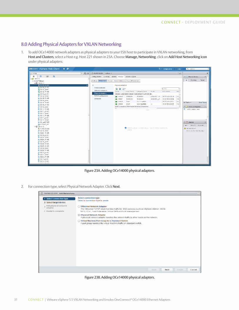
8.0 Adding Physical Adapters for VXLAN Networking
1. To add OCe14000 network adapters as physical adapters to your ESX host to participate in VXLAN networking, from Host and Clusters, select a Host e.g. Host 221 shown in 23A. Choose Manage, Networking, click on Add Host Networking icon under physical adapters:
Figure 23A. Adding OCe14000 physical adapters.
Figure 23B. Adding OCe14000 physical adapters.
2. For connection type, select Physical Network Adapter. Click Next.
32 CONNEC T | VMware vSphere 5.5 VXLAN Networking and Emulex OneConnect® OCe14000 Ethernet Adapters
CONNECT - DEPLOYMENT GU IDE
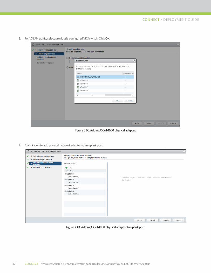
3. For VXLAN traffic, select previously configured VDS switch. Click OK.
Figure 23C. Adding OCe14000 physical adapter.
Figure 23D. Adding OCe14000 physical adapter to uplink port.
4. Click + icon to add physical network adapter to an uplink port.
33 CONNEC T | VMware vSphere 5.5 VXLAN Networking and Emulex OneConnect® OCe14000 Ethernet Adapters
CONNECT - DEPLOYMENT GU IDE
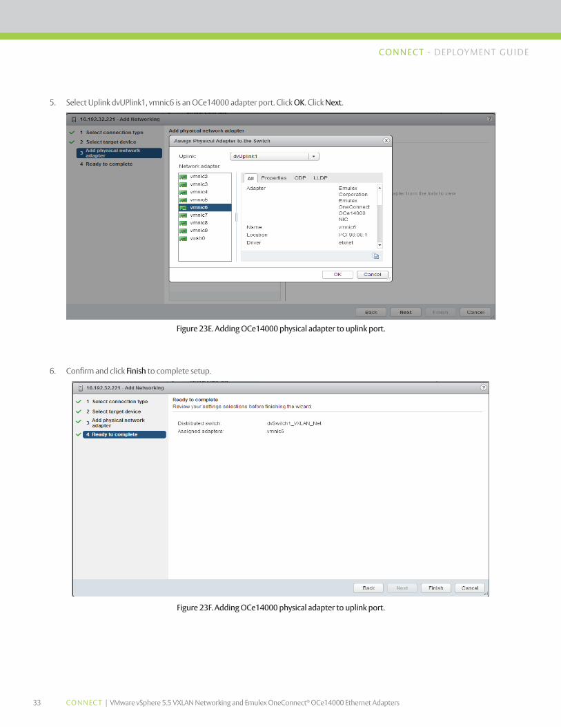
5. Select Uplink dvUPlink1, vmnic6 is an OCe14000 adapter port. Click OK. Click Next.
Figure 23E. Adding OCe14000 physical adapter to uplink port.
Figure 23F. Adding OCe14000 physical adapter to uplink port.
6. Confirm and click Finish to complete setup.

34 CONNEC T | VMware vSphere 5.5 VXLAN Networking and Emulex OneConnect® OCe14000 Ethernet Adapters
CONNECT - DEPLOYMENT GU IDE
Figure 23F. Adding OCe14000 physical adapter to uplink port.
Figure 24. Confirming OCe14000 VXLAN offloads enabled, disabled.
9.0 Confirming Emulex OCe14000 VXLAN Offloads Enabled, Disabled
1. Typically, VXLAN offload is enabled by default in recent OCe14000 driver and firmware releases. However, if you need to confirm that the OCe14000 VXLAN offload is enabled, use a SSH client to log in to your ESX host. Confirm all vmnic interfaces for OCe14000 network adapters are valid using a web client or use esxcli network nic list command to show all adapters in the ESX host.
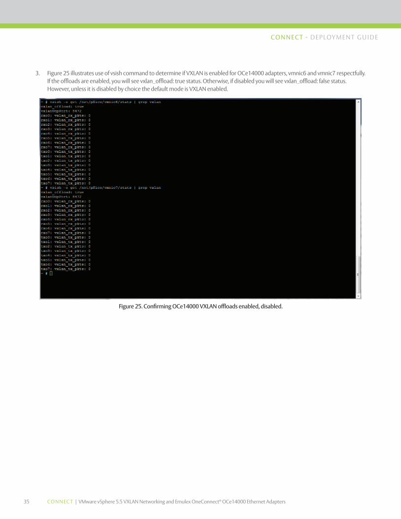
2. To confirm offload are enabled on each OCe14000 adapter, use the VMware VMkernel Sys info Shell (vsish) command: ~ # vsish –e get /net/pNics/vmnic6/stats | grep vxlan
35 CONNEC T | VMware vSphere 5.5 VXLAN Networking and Emulex OneConnect® OCe14000 Ethernet Adapters
CONNECT - DEPLOYMENT GU IDE
3. Figure 25 illustrates use of vsish command to determine if VXLAN is enabled for OCe14000 adapters, vmnic6 and vmnic7 respectfully. If the offloads are enabled, you will see vxlan_offload: true status. Otherwise, if disabled you will see vxlan_offload: false status. However, unless it is disabled by choice the default mode is VXLAN enabled.
Figure 25. Confirming OCe14000 VXLAN offloads enabled, disabled.

CONNECT - DEPLOYMENT GU IDE
ELX15-2124 · 9/14
World Headquarters 3333 Susan Street, Costa Mesa, CA 92626 +1 714 662 5600Bangalore, India +91 80 40156789 | Beijing, China +86 10 84400221Dublin, Ireland +35 3 (0) 1 652 1700 | Munich, Germany +49 (0) 89 97007 177Paris, France +33 (0) 158 580 022 | Tokyo, Japan +81 3 5325 3261 | Singapore +65 6866 3768Wokingham, United Kingdom +44 (0) 118 977 2929 | Brazil +55 11 3443 7735
©2014 Emulex, Inc. All rights reserved. This document refers to various companies and products by their trade names. In most cases, their respective companies claim these designations as trademarks or registered trademarks. This information is provided for reference only. Although this information is believed to be accurate and reliable at the time of publication, Emulex assumes no responsibility for errors or omissions. Emulex reserves the right to make changes or corrections without notice. This document is the property of Emulex and may not be duplicated without permission from the Company.
www.emulex.com
10.0 Conclusion This paper provides the administrator with steps to configure Emulex OneConnect OCe14000 network adapters in a basic VXLAN network with clustered ESX hosts. VMware network virtualization solutions with Emulex network adapters can provide enterprises and cloud infrastructures with greater flexibility and control over their networks.
In addition, Emulex VNeX technology can increase network performance as well as reduce the burden of VXLAN packet processing by CPUs in ESX hosts. This provides ESX host more processing capability, improved CPU effectiveness and server power efficiency.
11.0 References
VMware Compatibility Guide Release
VMware VSphere Documentation Release 5.5
VMware vCloud Networking and Security Documentation Release 5.5
Emulex Drivers Version 10.0 for VMware ESXi User Manual