connecting and routing the cables - cisco · step 10 use the cable routing clips in the inside of...
TRANSCRIPT

Cisco TelePresence System TX9000 and TX9200 AssemOL-27038-01
C H A P T E R 10
Connecting and Routing the CablesRevised: May 20, 2015, OL-27038-01This chapter provides you with information about connecting and routing the cables for the system, including first row table assembly, and includes the following sections:
• Labeling the Cables, page 10-1
• Labeling the Display Frame and Cable Runner, page 10-3
• Connecting and Routing Cables and Continuing Assembly of the First Row Table, page 10-5
• Connecting and Routing Cables in the Main Display Assembly, page 10-14
• Wiring Diagrams for CTS TX9000 and TX9200 Systems, page 10-17
• Where to Go Next, page 10-23
To continue installation of the first row table and start cabling of the system, complete the following steps.
Labeling the CablesThe following label kits are included with the TX9000 and TX9200:
Figure 10-1 shows an example of a label sheet for one of the cable kits.
Table 10-1 Cable Kits
Part Number Description Ctn
69-2345-01 Kit1—Cable Kit for TS1 Codec 12
69-2346-01 Kit 2—Cable Kit for TS2 Codec 13
69-2347-01 Kit 3—Cable Kit for TS3 Codec 14
69-2348-01 Kit 4—Cable Kit for TS4 Codec 15
69-2349-01 Kit 5—Cable Kit for System Cables 16
69-2350-01 Kit 6—Cable Kit for First Row 17
69-2351-01 (TX9200 only)
Kit 7—Cable Kit for Second Row (TX9200 only) 48
10-1bly, Use & Care, and Field-Replaceable Unit Guide
10-2Cisco TelePresence System TX9000 and TX9200 Assembly, Use & Care, and Field-Replaceable Unit Guide
OL-27038-01
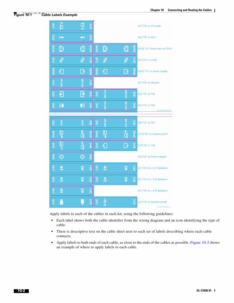
Chapter 10 Connecting and Routing the Cables Labeling the CablesFigure 10-1 Cable Labels Example
Apply labels to each of the cables in each kit, using the following guidelines:
• Each label shows both the cable identifier from the wiring diagram and an icon identifying the type of cable.
• There is descriptive text on the cable sheet next to each set of labels describing where each cable connects.
• Apply labels to both ends of each cable, as close to the ends of the cables as possible. Figure 10-2 shows an example of where to apply labels to each cable.

10-3Cisco TelePresence System TX9000 and TX9200 Assembly, Use & Care, and Field-Replaceable Unit Guide
OL-27038-01
Chapter 10 Connecting and Routing the Cables Labeling the Display Frame and Cable RunnerFigure 10-2 Label Positions on Cables
Labeling the Display Frame and Cable RunnerLabels are included for the display frame and cable runners to indicate where to route different types of cables. These labels have icons showing types of cables as shown in Figure 10-2.
Table 10-2 Cable Icons
Icon Description
Power cables
Ethernet cables

Chapter 10 Connecting and Routing the Cables Labeling the Display Frame and Cable Runner
Apply labels to the display frame pieces and the cable runner. This is to ensure that cables are routed through the correct channels. Use Figure 10-13 as a reference to determine where to apply the labels to the front of the display frame, and Figure 10-14 for the rear of the display frame.
Apply labels to the cable runner as shown in Figure 10-3. Be sure that, when you cable the system, you route the cables using this guide.
Display cables
Microphone cables
Presentation cables
Light cables
Speaker cables
Table 10-2 Cable Icons
Icon Description
10-4Cisco TelePresence System TX9000 and TX9200 Assembly, Use & Care, and Field-Replaceable Unit Guide
OL-27038-01

Chapter 10 Connecting and Routing the Cables Connecting and Routing Cables and Continuing Assembly of the First Row Table
Figure 10-3 Labels to Apply for Cable Runners
Connecting and Routing Cables and Continuing Assembly of the First Row Table
When routing cables, please keep the following guidelines in mind:
• Keep power, signal, Ethernet, and camera cables separate. Use Figure 10-3 as a reference to place the different cable types between the table and the main structure in the cable runner.
Note You do not need to separate cables that are less than 3 feet (1 meter) long.
• Use the Velcro cables and the clips that are provided in the table legs to route the cables in the first and second row tables.
• If you have extra cables after completing routing, use the method that works best for your installation to dress the excess cable. Some examples are:
– Use the Velcro tie-wraps to loop the excess cable together.
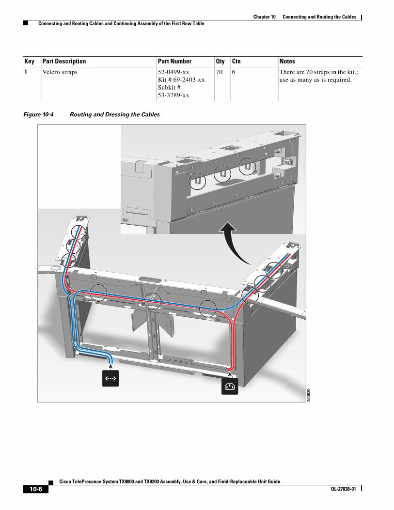
– Use the holes in the table legs as shown in Figure 10-4 to place the excess cable.
Step 1 Start to route the power, microphone, Touch device, Ethernet, and presentation cables through the cable runner base.
10-5Cisco TelePresence System TX9000 and TX9200 Assembly, Use & Care, and Field-Replaceable Unit Guide
OL-27038-01
Chapter 10 Connecting and Routing the Cables Connecting and Routing Cables and Continuing Assembly of the First Row Table
Figure 10-4 Routing and Dressing the Cables
Key Part Description Part Number Qty Ctn Notes
1 Velcro straps 52-0499-xxKit # 69-2403-xxSubkit # 53-3789-xx
70 6 There are 70 straps in the kit.; use as many as is required.
10-6Cisco TelePresence System TX9000 and TX9200 Assembly, Use & Care, and Field-Replaceable Unit Guide
OL-27038-01
Chapter 10 Connecting and Routing the Cables Connecting and Routing Cables and Continuing Assembly of the First Row Table
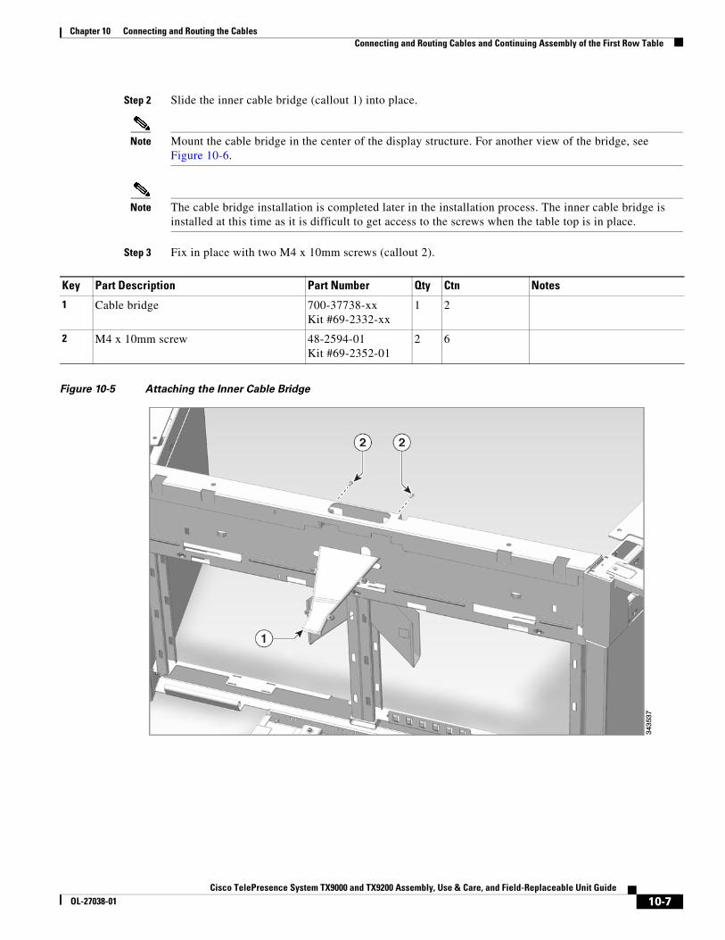
Step 2 Slide the inner cable bridge (callout 1) into place.
Note Mount the cable bridge in the center of the display structure. For another view of the bridge, see Figure 10-6.
Note The cable bridge installation is completed later in the installation process. The inner cable bridge is installed at this time as it is difficult to get access to the screws when the table top is in place.
Step 3 Fix in place with two M4 x 10mm screws (callout 2).
Figure 10-5 Attaching the Inner Cable Bridge
Key Part Description Part Number Qty Ctn Notes
1 Cable bridge 700-37738-xxKit #69-2332-xx
1 2
2 M4 x 10mm screw 48-2594-01Kit #69-2352-01
2 6
10-7Cisco TelePresence System TX9000 and TX9200 Assembly, Use & Care, and Field-Replaceable Unit Guide
OL-27038-01
Chapter 10 Connecting and Routing the Cables Connecting and Routing Cables and Continuing Assembly of the First Row Table
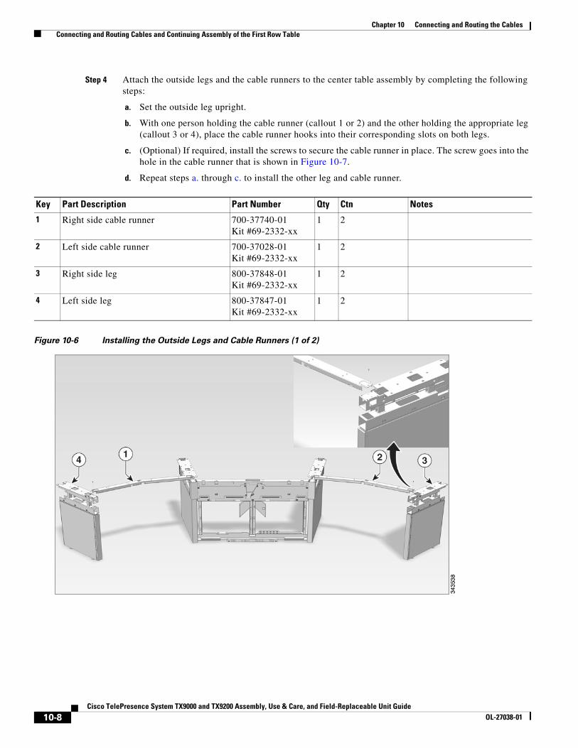
Step 4 Attach the outside legs and the cable runners to the center table assembly by completing the following steps:
a. Set the outside leg upright.
b. With one person holding the cable runner (callout 1 or 2) and the other holding the appropriate leg (callout 3 or 4), place the cable runner hooks into their corresponding slots on both legs.
c. (Optional) If required, install the screws to secure the cable runner in place. The screw goes into the hole in the cable runner that is shown in Figure 10-7.
d. Repeat steps a. through c. to install the other leg and cable runner.
Figure 10-6 Installing the Outside Legs and Cable Runners (1 of 2)
Key Part Description Part Number Qty Ctn Notes
1 Right side cable runner 700-37740-01Kit #69-2332-xx
1 2
2 Left side cable runner 700-37028-01Kit #69-2332-xx
1 2
3 Right side leg 800-37848-01Kit #69-2332-xx
1 2
4 Left side leg 800-37847-01Kit #69-2332-xx
1 2
10-8Cisco TelePresence System TX9000 and TX9200 Assembly, Use & Care, and Field-Replaceable Unit Guide
OL-27038-01

Chapter 10 Connecting and Routing the Cables Connecting and Routing Cables and Continuing Assembly of the First Row Table
Figure 10-7 Optional: Using a Screw to Connect the Cable Runner and the Table Leg (2 of 2)
Key Part Description Part Number Qty Ctn Notes
1 M5 flat head screw 48-0811-01Kit #69-2354-01
2 6
10-9Cisco TelePresence System TX9000 and TX9200 Assembly, Use & Care, and Field-Replaceable Unit Guide
OL-27038-01

Chapter 10 Connecting and Routing the Cables Connecting and Routing Cables and Continuing Assembly of the First Row Table
Step 5 Using a level, make sure that the side legs are the same height as the center structure.
Tip Diamond-shaped holes are provided on the sides of the legs; you can use a laser level and level the structure by using the center of the diamonds as a reference point.
Step 6 Make sure that center structure is still level, and level each side leg. Check levels in direction of the red lines that are shown in Figure 10-8.
Figure 10-8 Leveling the Table Structure
10-10Cisco TelePresence System TX9000 and TX9200 Assembly, Use & Care, and Field-Replaceable Unit Guide
OL-27038-01

Chapter 10 Connecting and Routing the Cables Connecting and Routing Cables and Continuing Assembly of the First Row Table
Step 7 Attach the outside plastic end caps to the outside table legs.
Note Figure 10-9 shows the front row table from the rear. Left and right are reversed.
Figure 10-9 Attaching the Outside Plastic End Caps
Key Part Description Part Number Qty Ctn Notes
1 End cap, left 700-37202-01Kit #69-2338-xx
1 2
2 End cap, right 700-37203-01Kit #69-2338-xx
1 2
10-11Cisco TelePresence System TX9000 and TX9200 Assembly, Use & Care, and Field-Replaceable Unit Guide
OL-27038-01

Chapter 10 Connecting and Routing the Cables Connecting and Routing Cables and Continuing Assembly of the First Row Table
Step 8 Assemble the outside power/Ethernet connections by completing the following steps:
a. Assemble power/Ethernet outlet (callout 1) into the lower hole in the power/Ethernet outlet cover (callout 2) using M3 nuts (callout 3).
b. Attach the 8 meter ethernet cable (callout 4) and, if required, a power cable to the power/Ethernet outlet.
c. Repeat Steps a. through b. for the other outside outlet.
Figure 10-10 Assembling the Outside Power/Ethernet Connections
Key Part Description Part Number Qty Ctn Notes
1 Power/Ethernet outlet See notes 2 Part number varies by country. Refer to Appendix C, “Region- and Country-Specific Power Cords and Table Leg Power Connectors,” for the correct part number.
2 Outside power/Ethernet outlet cover 800-37949-01Kit# 69-2338-xx
2 2
3 M3 nut 49-0833-01 8 Included with the outlets.
4 Front row Ethernet cable, 8 meters (20 feet)
37-1025-01Kit # 69-2350-01
2 17
10-12Cisco TelePresence System TX9000 and TX9200 Assembly, Use & Care, and Field-Replaceable Unit Guide
OL-27038-01
Chapter 10 Connecting and Routing the Cables Connecting and Routing Cables and Continuing Assembly of the First Row Table
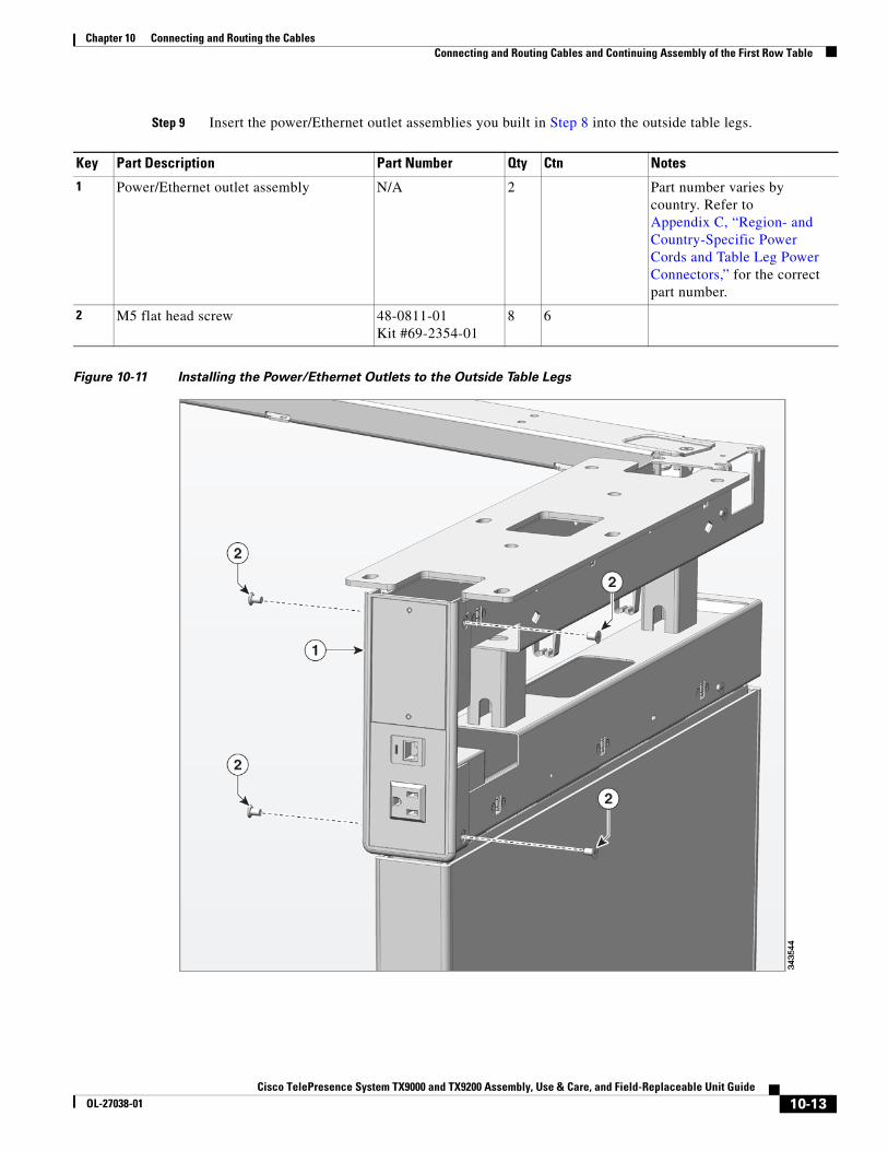
Step 9 Insert the power/Ethernet outlet assemblies you built in Step 8 into the outside table legs.
Figure 10-11 Installing the Power/Ethernet Outlets to the Outside Table Legs
Key Part Description Part Number Qty Ctn Notes
1 Power/Ethernet outlet assembly N/A 2 Part number varies by country. Refer to Appendix C, “Region- and Country-Specific Power Cords and Table Leg Power Connectors,” for the correct part number.
2 M5 flat head screw 48-0811-01Kit #69-2354-01
8 6
10-13Cisco TelePresence System TX9000 and TX9200 Assembly, Use & Care, and Field-Replaceable Unit Guide
OL-27038-01
Chapter 10 Connecting and Routing the Cables Connecting and Routing Cables in the Main Display Assembly
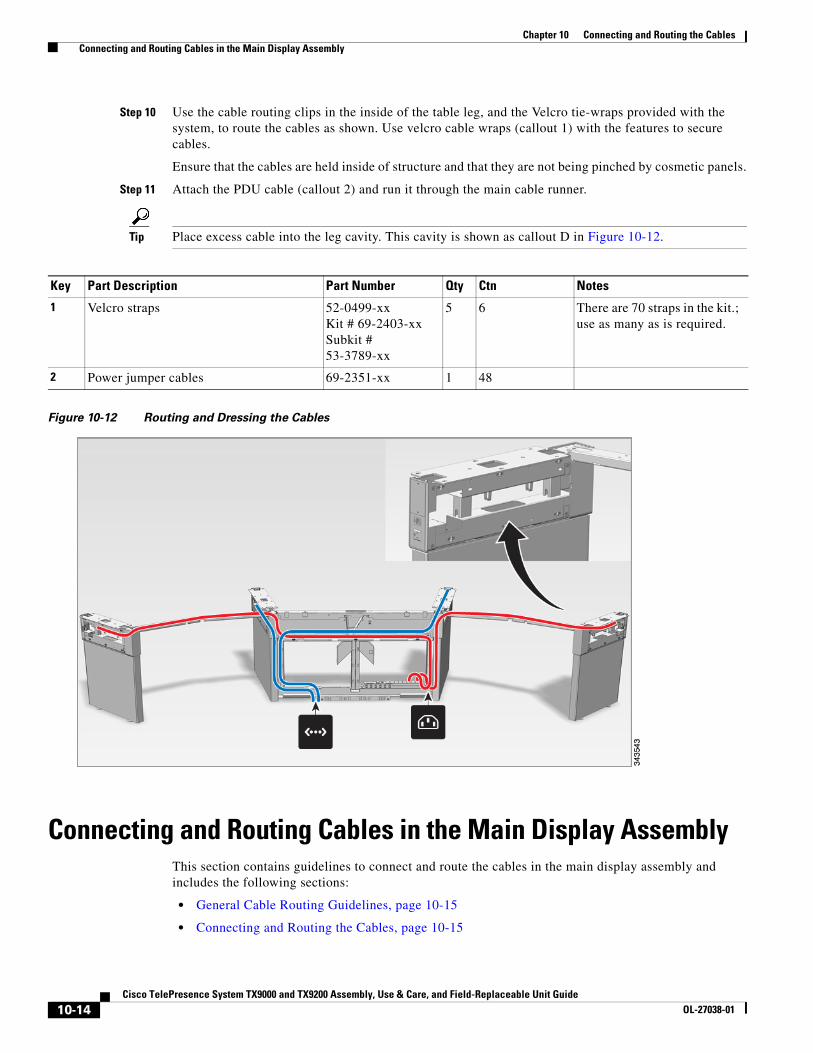
Step 10 Use the cable routing clips in the inside of the table leg, and the Velcro tie-wraps provided with the system, to route the cables as shown. Use velcro cable wraps (callout 1) with the features to secure cables.
Ensure that the cables are held inside of structure and that they are not being pinched by cosmetic panels.
Step 11 Attach the PDU cable (callout 2) and run it through the main cable runner.
Tip Place excess cable into the leg cavity. This cavity is shown as callout D in Figure 10-12.
Figure 10-12 Routing and Dressing the Cables
Connecting and Routing Cables in the Main Display AssemblyThis section contains guidelines to connect and route the cables in the main display assembly and includes the following sections:
• General Cable Routing Guidelines, page 10-15
• Connecting and Routing the Cables, page 10-15
Key Part Description Part Number Qty Ctn Notes
1 Velcro straps 52-0499-xxKit # 69-2403-xxSubkit # 53-3789-xx
5 6 There are 70 straps in the kit.; use as many as is required.
2 Power jumper cables 69-2351-xx 1 48
10-14Cisco TelePresence System TX9000 and TX9200 Assembly, Use & Care, and Field-Replaceable Unit Guide
OL-27038-01
Chapter 10 Connecting and Routing the Cables Connecting and Routing Cables in the Main Display Assembly
• Wiring Diagrams for CTS TX9000 and TX9200 Systems, page 10-17
General Cable Routing GuidelinesWhen routing cables, please keep the following guidelines in mind:
• Keep power, signal, Ethernet, and camera cables separate.
Note You do not need to separate cables that are less than 3 feet (1 meter) long.
• Use the Velcro cables and the clips that are provided in the table legs to route the cables in the first and second row tables.
• If you have extra cables after completing routing, use the method that works best for your installation to dress the excess cable. Some examples are:
– Use the Velcro tie-wraps to loop the excess cable together.
– Use the holes in the table legs as shown in Figure 10-4 to place the excess cable.
Connecting and Routing the CablesTo connect and route cables:
Step 1 Route the power and, if necessary, Ethernet cables through the rear of the reflector to the power and Ethernet receptacles in the wall.
Caution Be sure to observe all local safety codes when cabling the system.
Use the following steps as guidelines:
• Free-standing systems only:
– There is an access slot (mouse hole) in the bottom center of the center reflector panel; if possible, route the cables through this slot. Be sure to keep the power and Ethernet cables separated.
• Wall-mounted systems only:
– Remove the access panels as shown in Figure 3-5 and Figure 3-6 and route the cables to the wall outlets through these panels.
– If the outlets are located at the base of the wall, you can raise the entire wall so that it clears the wall.
Step 2 Connect the cables for the entire system. See Figure 10-13 and Figure 10-14 for diagrams on how to route cables in the main display frame. See Figure 10-16 for a complete cabling diagram and additional information about connecting and routing cables.
Note When routing cables in the front of the main display frame, bundle cables together using velcro ties, and use the shelf on the interior of the facade brackets to support the cable bundles.
10-15Cisco TelePresence System TX9000 and TX9200 Assembly, Use & Care, and Field-Replaceable Unit Guide
OL-27038-01

Chapter 10 Connecting and Routing the Cables Connecting and Routing Cables in the Main Display Assembly
Figure 10-13 Front View of Main Display Frame Cable Routing
Figure 10-14 Rear View of Main Display Frame Cable Routing
Note You cannot add the cable for the Touch device, presentation cable, or microphone cable until you install the table tops. For instructions to connect and route these cables, see Chapter 11, “Completing Installation of the First Row Table.” For additional instructions to route the second row cables, see Chapter 12, “Building the Second Row Table (TX9200 Systems Only).”
10-16Cisco TelePresence System TX9000 and TX9200 Assembly, Use & Care, and Field-Replaceable Unit Guide
OL-27038-01

Chapter 10 Connecting and Routing the Cables Wiring Diagrams for CTS TX9000 and TX9200 Systems
Tip Use the Velcro tie wraps to coil and bundle excess cable.
Note Be sure to keep the types of cable separate. You can join cables of different types as long as the cables are less than 3 feet (1 meter) long.
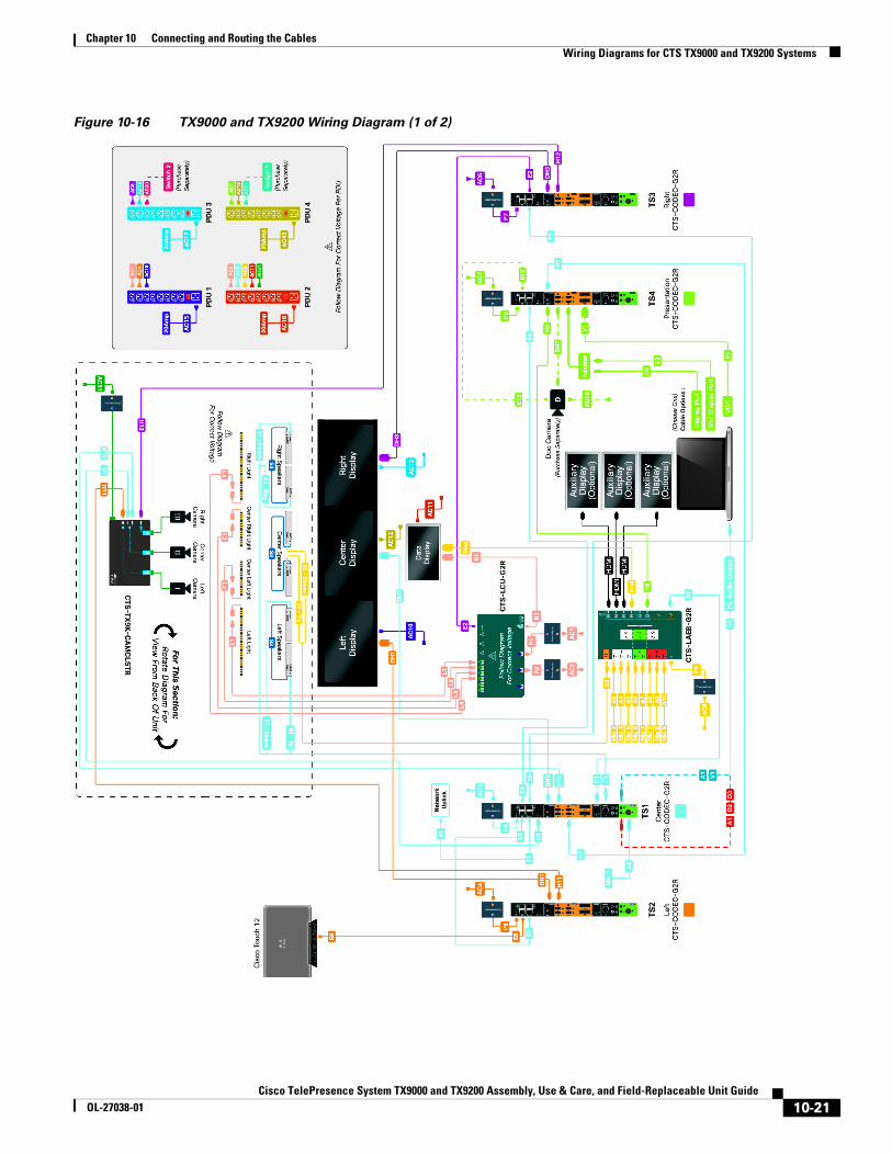
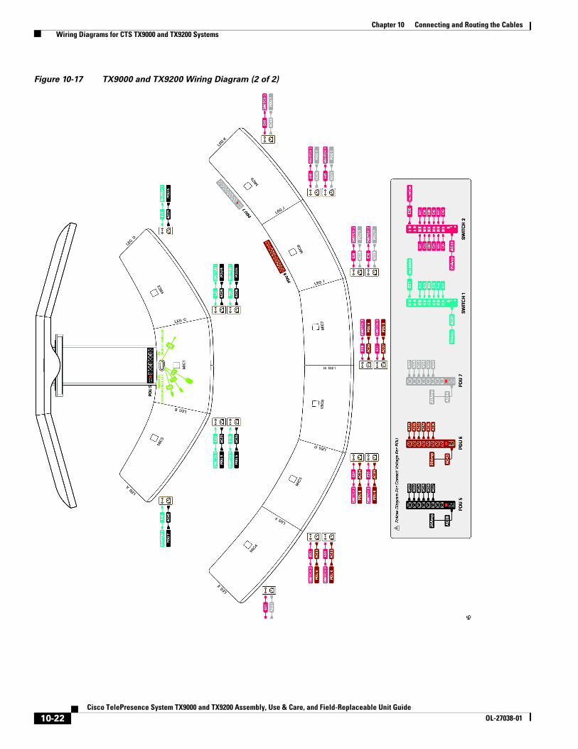
Wiring Diagrams for CTS TX9000 and TX9200 SystemsFigure 10-16 and Figure 10-17 show the wiring diagram for the TX9000 and TX9200 systems.
Note Click here for a high-resolution PDF version of the wiring diagram.
Click here for a printable version that is two pages and fits on 8 1/2 x 11-inch paper.
Note When connecting the cable that connects the TS1 codec to the audio/video expansion unit (labeled D1 on the wiring diagram), be sure to connect to the port labeled “AUX” on the audio/video expansion unit.
Using the Correct DVI Port When Connecting the Display CablesWhen you connect the DVI cables to the display, be sure to plug the cable into the white port labeled “DVI”. This is the connection on the left in Figure 10-15. Do not plug the DVI cable into the orange port labeled “AUX” or the display goes into a “deep sleep” mode and will not become active.
Figure 10-15 DVI and Aux Ports on the Display
10-17Cisco TelePresence System TX9000 and TX9200 Assembly, Use & Care, and Field-Replaceable Unit Guide
OL-27038-01
Chapter 10 Connecting and Routing the Cables Wiring Diagrams for CTS TX9000 and TX9200 Systems
Connecting the Audio Cable for Shared PresentationsThe audio connection for the presentation cable on the codec is different based on the cable you use for presentations. If you use a VGA-to-VGA cable, use the audio connection on the codec labeled with an icon of a computer. If you use a HD video (uses HDMI connector)-to-HD video (uses HDMI connector), HD video (uses HDMI connector)-to-DisplayPort, or HD video (uses HDMI connector)-to-Mini DisplayPort cable, use the audio connection labeled “Aux” on the codec. Figure 10-16 shows both connections.
Determining the Correct Cables to Use Each cable in the cabling diagram has an alphanumeric identifier. Table 10-3 through Table 10-8 show the mapping between the part numbering for the cables in the cable kit and the alphanumeric identifiers in the cabling diagram.
Table 10-3 Cross-Reference for Cables in the Cable Kit for TS1 Codec, Part Number 69-2345-xx
ID in Cabling Diagram
Cable Part Number Part Description Qty
Chapter Parts List Reference
P4 37-1331-xx Power adapter cord, 0.8m 1 Chapter 10
D1 37-1335-xx CABASY,WIRE HARNESS,DP-DP,NON-STND,1.5m
1 Chapter 10
H10, H7 37-1381-xx Cable, HD video (uses HDMI connector) - HD video (uses HDMI connector), 5m
2 Chapter 10
A1 37-1385-xx Cable, speaker cable, 6.5m 1 Chapter 10
E3, E4, E5 37-1386-xx Ethernet cable, 5m 3 Chapter 10
DH2 37-1387-xx Cable, HD video (uses HDMI connector) - DVI, 3m
1 Chapter 10
U1 37-1394-xx Cable, USB - USB, 5m 1 Chapter 10
E1 37-1409-xx Ethernet cable, 9m 2 Chapter 11
N/A 47-24782-xx Cable labels, TS1 codec 1 Chapter 10
Table 10-4 Cross-Reference for Cables in the Cable Kit for TS2 Codec, Part Number 69-2346-xx
ID in Cabling Diagram
Cable Part Number Part Description Qty
Chapter Parts List Reference
P6 37-1331-xx Power cord, US, 0.8m 1 Chapter 10
H11 37-1381-xx Cable, HD video (uses HDMI connector) - HD video (uses HDMI connector), 5m
1 Chapter 10
E3 37-1409-xx Ethernet cable, 9m 1 Chapter 10
DH1 37-1387-xx Cable, HD video (uses HDMI connector) - DVI, 3m
1 Chapter 10
N/a 47-24783-xx Cable labels, TS2 codec 1 Chapter 10
10-18Cisco TelePresence System TX9000 and TX9200 Assembly, Use & Care, and Field-Replaceable Unit Guide
OL-27038-01
Chapter 10 Connecting and Routing the Cables Wiring Diagrams for CTS TX9000 and TX9200 Systems
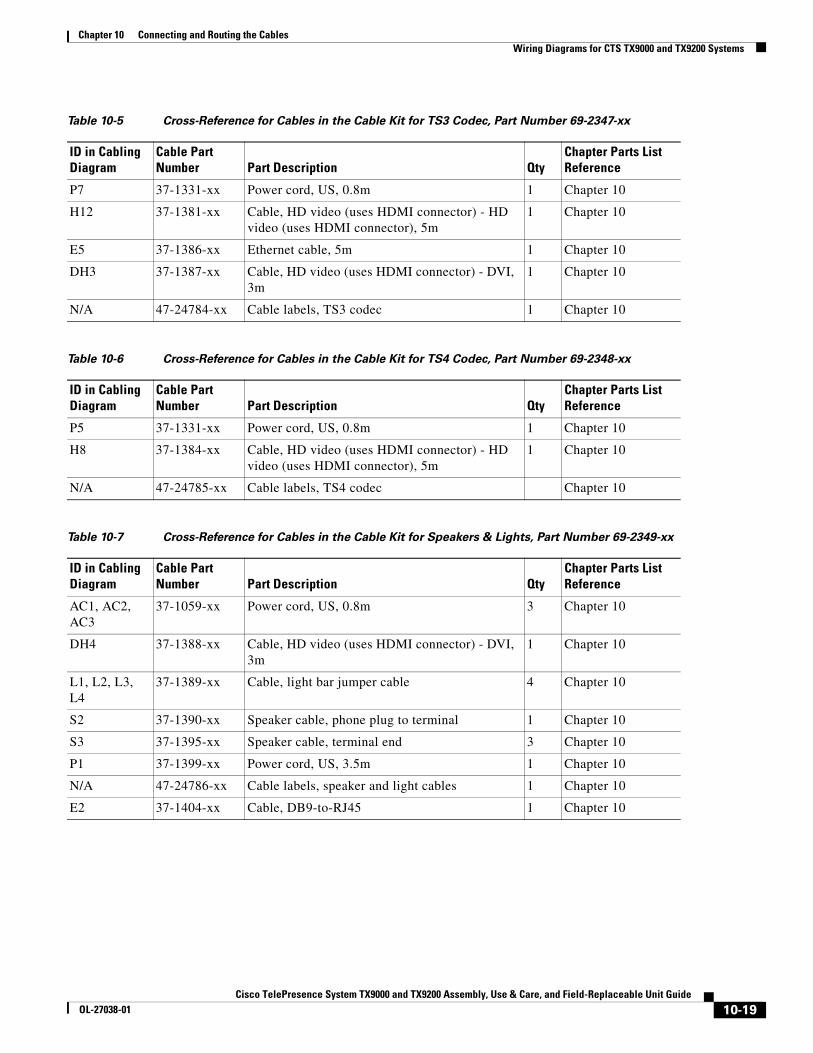
Table 10-5 Cross-Reference for Cables in the Cable Kit for TS3 Codec, Part Number 69-2347-xx
ID in Cabling Diagram
Cable Part Number Part Description Qty
Chapter Parts List Reference
P7 37-1331-xx Power cord, US, 0.8m 1 Chapter 10
H12 37-1381-xx Cable, HD video (uses HDMI connector) - HD video (uses HDMI connector), 5m
1 Chapter 10
E5 37-1386-xx Ethernet cable, 5m 1 Chapter 10
DH3 37-1387-xx Cable, HD video (uses HDMI connector) - DVI, 3m
1 Chapter 10
N/A 47-24784-xx Cable labels, TS3 codec 1 Chapter 10
Table 10-6 Cross-Reference for Cables in the Cable Kit for TS4 Codec, Part Number 69-2348-xx
ID in Cabling Diagram
Cable Part Number Part Description Qty
Chapter Parts List Reference
P5 37-1331-xx Power cord, US, 0.8m 1 Chapter 10
H8 37-1384-xx Cable, HD video (uses HDMI connector) - HD video (uses HDMI connector), 5m
1 Chapter 10
N/A 47-24785-xx Cable labels, TS4 codec Chapter 10
Table 10-7 Cross-Reference for Cables in the Cable Kit for Speakers & Lights, Part Number 69-2349-xx
ID in Cabling Diagram
Cable Part Number Part Description Qty
Chapter Parts List Reference
AC1, AC2, AC3
37-1059-xx Power cord, US, 0.8m 3 Chapter 10
DH4 37-1388-xx Cable, HD video (uses HDMI connector) - DVI, 3m
1 Chapter 10
L1, L2, L3, L4
37-1389-xx Cable, light bar jumper cable 4 Chapter 10
S2 37-1390-xx Speaker cable, phone plug to terminal 1 Chapter 10
S3 37-1395-xx Speaker cable, terminal end 3 Chapter 10
P1 37-1399-xx Power cord, US, 3.5m 1 Chapter 10
N/A 47-24786-xx Cable labels, speaker and light cables 1 Chapter 10
E2 37-1404-xx Cable, DB9-to-RJ45 1 Chapter 10
10-19Cisco TelePresence System TX9000 and TX9200 Assembly, Use & Care, and Field-Replaceable Unit Guide
OL-27038-01

Chapter 10 Connecting and Routing the Cables Wiring Diagrams for CTS TX9000 and TX9200 Systems
Table 10-8 Cross-Reference for Cables in the Cable Kit for First Row Table, Part Number 69-2350-xx
ID in Cabling Diagram
Cable Part Number Part Description Qty
Chapter Parts List Reference
E23-E26 37-1382-xx Ethernet cable, 6m 4 Chapters 9, 10
E27, E40 37-1025-xx Ethernet cable, 8m 2 Chapters 9, 10
N/A 47-24787-xx Cable labels, 1st row Ethernet, power, and microphone cables
1 Chapter 10
N/A 700-37866-xx Cable management ball 2 Chapter 11
10-20Cisco TelePresence System TX9000 and TX9200 Assembly, Use & Care, and Field-Replaceable Unit Guide
OL-27038-01
Chapter 10 Connecting and Routing the Cables Wiring Diagrams for CTS TX9000 and TX9200 Systems
Figure 10-16 TX9000 and TX9200 Wiring Diagram (1 of 2)
10-21Cisco TelePresence System TX9000 and TX9200 Assembly, Use & Care, and Field-Replaceable Unit Guide
OL-27038-01
Chapter 10 Connecting and Routing the Cables Wiring Diagrams for CTS TX9000 and TX9200 Systems
Figure 10-17 TX9000 and TX9200 Wiring Diagram (2 of 2)
10-22Cisco TelePresence System TX9000 and TX9200 Assembly, Use & Care, and Field-Replaceable Unit Guide
OL-27038-01

Chapter 10 Connecting and Routing the Cables Where to Go Next
Where to Go NextContinue to Chapter 11, “Completing Installation of the First Row Table,” to complete assembly of the first row.
10-23Cisco TelePresence System TX9000 and TX9200 Assembly, Use & Care, and Field-Replaceable Unit Guide
OL-27038-01

Chapter 10 Connecting and Routing the Cables Where to Go Next
10-24Cisco TelePresence System TX9000 and TX9200 Assembly, Use & Care, and Field-Replaceable Unit Guide
OL-27038-01