considerations for invstigation and reliablity improvement ... · considerations for invstigation...
TRANSCRIPT

CONSIDERATIONS for INVSTIGATION and RELIABLITY
IMPROVEMENT of SVC SYSTEMS M. A. Reynolds P.E.
POWER ENGINEERS Inc Power Delivery
Portland, Oregon, USA [email protected]
B. C. Furumasu P.E. POWER ENGINEERS Inc
Power Delivery Portland, Oregon, USA
W.H.Litzenberger Fellow IEEE POWER ENGINEERS Inc
Power Delivery Portland, Oregon, USA
1
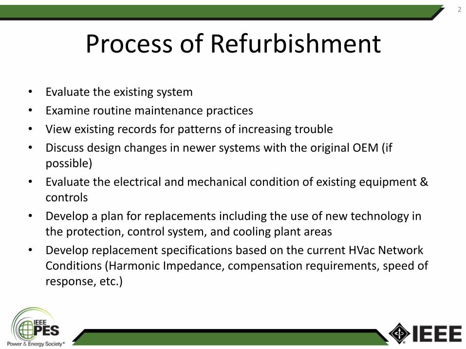
Process of Refurbishment
• Evaluate the existing system
• Examine routine maintenance practices
• View existing records for patterns of increasing trouble
• Discuss design changes in newer systems with the original OEM (if possible)
• Evaluate the electrical and mechanical condition of existing equipment & controls
• Develop a plan for replacements including the use of new technology in the protection, control system, and cooling plant areas
• Develop replacement specifications based on the current HVac Network Conditions (Harmonic Impedance, compensation requirements, speed of response, etc.)
2

Historical Record of Forced Outages & Trouble Spots
• IEEE WG(s)
• CIGRE WG(s)
• EPRI Reports
• Industrial Reports
• Maintenance Reports
3

Typical Distribution of Subsystem Outages
4

Typical Distribution of Subsystem Outages of Newer Projects
5

Balance of Plant Condition
• Rotating machinery – vibration and ultrasonic signature analysis
• Medium and high current bus and connections
• Medium Voltage and Low voltage distribution systems analysis
• Control System hardware and software manufacturer support levels.
6

Power Electronic Condition
• Thyristor valve mechanical aging and corrosion conditions including both within the dielectric and non-dielectric piping and connections.
• Thyristor valve electronics (VE) cards and the various snubber and ancillary electronics components need to be examined
7

Oil & Gas Quality (Condition)
• Outdoor apparatus examination including Dissolved Gas Analysis (DGA) samples for oil filled transformers, visual and thermal analysis of dry type transformers, and SF6 Gas analysis for SF6 switchgear.
8

Cooling System Components Aging
• Cooling system components subject to outdoor weather such as dry or wet surface coolers need complete examination for the effects of corrosion, bird nesting, and mechanical soundness
9

Cooling System Components Aging (continued)
• Since many of these items receive infrequent cycling, bearing corrosion and general motor conditions (such as wet windings and rotor corrosion need to be determined by disassembly and visual inspection.
10

Cooling System Components Aging (continued)
• Internal piping examination including examination of any area of the piping that is suspect of cavitation activity. All bolted connections need to be checked for leaks and tightness.
11

Advances in Cooling System Controls
12
•Cooling Plant Controls can be improved
•Modern IGBT Motor Controls Offer major
improvements in visibility and operational
monitors
•Self diagnostics with modern network
solutions allow remote and local monitoring at
even more detail levels
•Modern systems can be fitted with ware
algorithms to Predict Time to Failure
•Better soft starting allows improved motor
winding and bearing ware
Comparison of Inverter Output (2-Level vs. 3-Level)
Circuits Line-to-Line to Line Voltage Waveform
Comparison of Inverter Output Circuit Line-to-Line to Line
Voltage Waveform
Motor Bearing and Vibration (after 5000 Hours)

Full Level Performance Testing
• Full performance cycle testing of the SVC to the limits of the capacitive and inductive ranges, with a full set of thermal measurements in all high current areas (connections, jumpers and bolted connections)
13

SVC Plant Records
• Operational records and review of equipment cycle counters will highlight possible apparatus which have high duty cycle deterioration. Review DFR fault records to ascertain the number of fault clearing cycle’s switchgear has been subjected to.
14

SCADA INTERFACE IMPROVEMENTS
• Determine HMI operational capability from both local and remote (via SCADA control) locations, note any shortcomings
• Determine if the sequence of events (SER) function and DFR functionality are operational and capable of capturing significant event activity subjected to the SVC in the network it serves.
15

Improved Networking Opportunities
• Other protective relays may have aged to the point that new microprocessor based systems featuring self-diagnostics may offer a very low cost and much improved maintenance features to the SVC. These new relays can be easily networked to the SER and SVC control system using IEC-61850, DNP3 and other recognized protocols.
16

Relay & Protection Improvement
• If major work is undertaken to replace SVC subsystems, this is an ideal opportunity to update he protection & control systems with modern microprocessor (and networkable relays).
17

References
• IEEE Guide 1031-2011 SVC Specification Guide
• IEEE Guide 1303-2011 SVC Field Testing Guide
• SVC Refurbishment Special Publication SVC User List 2011 v12
• IEEE 1221-1995 Guide for Fire Hazard Assessment
• EPRI Life Extension Guidelines for Static VAR Compensators 2009
• CIGRE Publications Located in the SC B4 Subject Area
18

Questions
M. A. Reynolds P.E. POWER ENGINEERS Inc
Power Delivery
Portland, Oregon, USA 97219
+1.503.892.6733 (Office)
19