contemporary radiographic evaluation of the …c1-preview.prosites.com/36100/wy/docs/book/chap 8 -...
TRANSCRIPT

110
C H A P T E R 8
CONTEMPORARY RADIOGRAPHIC EVALUATION
OF THE IMPLANT CANDIDATE
The use of endosseous implants, as well as other types of designs such as subperiosteal and transosseous, for dental reha-bilitation of patients represents one of the most technologically advanced forms of dentistry available today. 1-4 Radiographs are typically the fi rst window for seeing whether or not patients are candidates for dental implants. In fact, there are situations in which taking the appropriate dental radiograph is all that is needed to place a simple implant. However, in complex cases, in which the patient ’ s medical history indicates signifi cant medical problems, or a clinical exam shows diminished bone or other anatomical areas of concern, a more extensive radio-graphic evaluation is warranted. 5-9 This has often required sending a patient to a local hospital to have a medical computed tomography (CT) scan taken.
Since the previous edition of this book, cone beam com puted tomography (CBCT) has become widely available. Cone beam 3-D dental imaging brings the advantages of hos-pital-based CT scans into the dental practitioner ’ s offi ce. Unlike conventional two-dimensional radiographs, CBCT offers 3-D views of the mouth, face, and jaw from any direc-tion ( Figure 8-1 ).
Additionally, software provided by unit manufacturers and third party vendors can enhance grayscale and add pseudo-color to delineate both hard and soft tissue densities ( Figure 8-2 ). With these advances, it is possible to clearly see vital anatomical structures, including soft tissue. Some products will even overlay the patient ’ s facial image onto the radio-graphic image ( Figure 8-3 ). CBCT, in combination with the appropriate software, thus eliminates much of the guesswork
that was previously necessary when trying to determine place-ment of an implant from a two-dimensional grayscale image.
In addition to image enhancement, there are software pro-grams that offer advanced diagnostic analysis. These programs allow the dentist/surgeon to use the data obtained from the cone beam image for surgical planning, and in some cases, even rapid prototyping. In all instances, because the images are digitized, they can easily be sent over the Internet, allowing for easy collaboration and consultation on cases.
Two-Dimensional Views Periapical and Panoramic Images: Digital Versus Conventional In many practices, digital radiographs ( Figure 8-4, A ) have largely replaced conventional fi lms. As a result, many dentists will fi nd they are already familiar with the combination of rapid imaging and computer display that cone beam units provide. Digital images will not fade and can be stored on a computer along with other patient information. They can be manipulated easily on a computer, where angles can be rotated, grayscale intensities can be adjusted, negative and positive can be reversed, and pseudo-color can be added to enhance con-trast to facilitate immediate diagnosis. These are all major advances over trying to make a diagnosis by examining fi lms by hand.
The downside is that digitized two-dimensional radio-graphs cannot provide any information about the third dimen-
Joel L. Rosenlicht
Ryaz Ansari

Chapter 8 Contemporary Radiographic Evaluation of the Implant Candidate 111
Figure 8-1. A, A digital panorex showing 2-D view of impacted canine. Compare this to the 3-D cone beam images of this same patient. A typical 40-second cone beam scan resulted in compre-hensive imaging of the maxillofacial region, and the i-CATVision software processed this information into the views shown here. B, Clockwise from top left: right lateral, left lateral, anterior, and posterior cephalometric views. ( A, Courtesy Gendex Dental Systems, Des Plaines, IL)
A
B
Continued

112 Chapter 8 Contemporary Radiographic Evaluation of the Implant Candidate
C
C, Clockwise from the top left: axial view, panoramic view, sagittal view, and 3-D rendering. Note the amount of additional information available compared to the conventional 2-D radiograph. (Courtesy Imaging Sciences International Inc., Hatfi eld, PA.)
Figure 8-1, cont’d.
Figure 8-2. Digital images allow for custom coloring of soft tissues to assess airway anatomy and sinus morphology (InVivo Dental 3D Imaging Software). They provide information of the entire maxil-lofacial region. (Courtesy Anatomage, San Jose, CA.)

Chapter 8 Contemporary Radiographic Evaluation of the Implant Candidate 113
Figure 8-3. A, Soft tissue anatomy captured using CBCT technology (i-CATVision software). B, Skeletal anatomy captured from CBCT data and superimposed on a digital photograph (InVivo-Dental 3D Imaging Software). This allows the practitioner to see how dental and skeletal changes will alter facial soft tissue. ( A, Courtesy Imaging Sciences International Inc., Hatfi eld, PA. B, Courtesy Anatomage, San Jose, CA.)
A B
sion, so the dentist is still forced to estimate implant depth and width, just as with conventional fi lms. Nevertheless, in cases involving the extraction of a tooth caused by a lack of peri-odontal support, root fracture, or nonresolving periapical pathological condition, periapical radiographic images ( Figure 8-4, B ) still provide useful information. They show the loca-tion of adjacent roots and any opaque foreign bodies that may be in the area being considered for implant placement.
Computed Tomography and Digital Images The limitations of radiographs, both fi lm and digital, are well known:
1. They cannot show depth and width. 2. They cannot distinguish between types of hard and soft
tissues. 3. They can distinguish tissue density only at the grossest
level (bone/not bone). CT solved these problems. CT was developed by British
engineer Godfrey Hounsfi eld, who received a patent on CT in 1972 and the Nobel Prize in 1979. Hounsfi eld described CT as a reverse of radar; whereas radar sweeps out to cover a land-scape, CT sweeps inward to cover the interior of an object or body.
Tomo is Greek for slice. A radiographic scanner takes slices through the patient ’ s body and the slices are then composited into an image with more depth than conventional radiographs. Tomography had been tried in the 1940s with fi lm-based systems, but its potential could not be fully realized because of
blurring. Hounsfi eld calculated the necessary math to elimi-nate blur and engineered the fi rst CT scanner, which partly rotated around the patient ’ s head. 10 , 11 (A bit of trivia to enter-tain nervous patients. The Beatles deserve credit for making CT research possible. Hounsfi eld developed CT while working as an engineer at British music publishing giant, EMI. Although EMI would later sell off their technology division, in the 1970s they invested the profi ts from the Beatles ’ hit records into engineering R & D . ) 12 , 13
CT technology takes advantage of radiographic attenua-tion. Radiographic intensity attenuates at different rates in different types of tissue. Hounsfi eld theorized that if tissue were penetrated by rays from different angles, one could cal-culate the attenuation rates and thus reconstruct the structure of the tissue. (Separately, South African physicist Allan Cormack worked out similar calculations. He shared the Nobel Prize with Hounsfi eld.) By contrast, in a conventional radiographic, one ray evenly penetrates all the tissue. This is the way the inventor of the x-ray, William Conrad R ö ntgen, famously imaged his wife ’ s left hand in 1895.
The CT beam “ cuts ” through the body to image a trans-verse slice of tissue. In addition to the x (horizontal) and y (vertical) coordinates of a two-dimensional radiograph, the CT slice has a z plane, representing depth. According to CT pioneer Willi Kalender, a German physicist and author of Computed Tomography , the slice itself consists of “ discrete cubic volume elements ” 14 that encompass the numeric values of the tissue density. In more concrete terms, imagine a CT slice as a mosaic made from dyed sugar cubes. The individually colored sugar cubes are “ voxels, ” Kalender ’ s cubic volume ele-ments. Each voxel is a complete description of a tiny part of

114 Chapter 8 Contemporary Radiographic Evaluation of the Implant Candidate
Figure 8-4. Digital radiographs have numerous advantages over conventional radiographs. They can be handled like other digital fi les, making it easy to change contrast and color and email them. However, they are limited when compared to three-dimensional images. (Courtesy DENTRIX, Ameri-can Fork, UT.)
Figure 8-5. A voxel is a three-dimensional pixel.
Pixel
Y-axis
Z-axis
X-axisVoxel
the whole slice. The three-dimensional voxels are seen on monitors as two-dimensional picture elements or “ pixels ” ( Figure 8-5 ). How much chromatic information each pixel can display is determined by the number of “ bits ” (binary digits) of which it is composed. (The bits are the underlying 0,1 computer code).
In CT scans from the early 1970s (when monitor resolution was low) scans were composed of large grayscale squares that looked like patchwork quilt interpretations of human organs. As monitor resolution improved, the number of pixels per square inch increased while their size correspondingly decreased. The dimensions of the voxels followed suit, result-ing in crisper and more detailed images.
As part of his work, Hounsfi eld created a scale for calculat-ing tissue density based on CT pixel intensity, which is far more sensitive than fi lm. Air appears black on x-ray fi lm, and bone appears white. CT scanning generates over 200 shades of gray, which distinguish the density of the tissues between those extremes. Called Hounsfi eld units, the scale is generally given as − 1000 (air) to +1000 (bone), with water at 0. Because the scale ’ s values are based on the equation to calculate attenua-tion, 14 , 15 it can actually go both above and below those numbers.
According to Kalender, “ CT measures and computes the spatial distribution of the linear attenuation coeffi cient μ ( x , y ). … For an arbitrary tissue T with attenuation coeffi cient μ t the CT value is defi ned as: CT value = ( μ t − μ water )/ μ water • 1000 HU. ” 14 Kalender notes, however, that human beings can generally perceive only 60 to 80 shades of gray, far fewer than the 4096 levels of the full Hounsfi eld scale. On this scale, dense medullary bone would be approximately 400 (150-850) and cortical bone 1500 (850-2000).
Chapter 8 Contemporary Radiographic Evaluation of the Implant Candidate 115
Hounsfi eld ’ s prototype took 9 days to make an image. Contemporary CT machines can take scans in a breath-hold. The increase in speed is a result of design changes. By the late 1970s, the sequential scanning procedure (now known as con-ventional CT) had become established. In this method, the patient lies still on a table that slowly slides between an x-ray beam and an x-ray detector. Rather than pointing straight on at one area, the beam makes a 360-degree revolution around a “ slice ” of the patient ’ s body. Although scan times are sub-stantially reduced with this method, it is still a time-consuming procedure due to the fact that the table pauses between slices and then moves incrementally to image the next slice. There is always a risk of patient movement distorting images, as well as the risk that important anomalies might be missed if they are below the threshold of the slice widths. Nevertheless, a composite image can be reconstructed from the slices that gives a view of the soft tissue not possible with conventional radio-graphs. Conventional CT produces images that look like a blade has sliced clean through the body. 16 , 17
In 1989, Kalender altered the design of the scanners so that the patient went through in one continuous motion as the x-ray spiraled around the body. Spiral CT (also known as helical CT) greatly reduces the time needed for scans and the artifacts introduced by patient movement. Most important, because there is less jitter than with conventional CT it is easier to match slices to build volumetric images that look like sculp-tures of tissues and bone. The detail of these stacked images has been further enhanced with the recent introduction of multidetector CT machines, which take multiple slice images during each x-ray revolution.
From the point of view of the dental practitioner, both conventional and spiral CT scans have the same disadvantages. First, due to the need to take hundreds of scans, the patient can be exposed to high levels of radiation. There is a risk/benefi t analysis to this exposure. It may be an acceptable risk for detecting a brain tumor but could be considered excessive for certain dental procedures. Second, conventional and spiral CT scanners are extremely expensive, hospital-based devices. This necessitates a hospital visit, which inconveniences and potentially frightens patients and, more often than not, can be signifi cantly expensive. Most important, it is highly unlikely that a dental professional will be present while the procedure is performed. The hospital ’ s radiologist may not be fully con-versant with the surgical issues at hand and may at best be guessing at what the dentist most needs to see. When the scans are received the dentist may once again be forced to estimate the best position for implant placement.
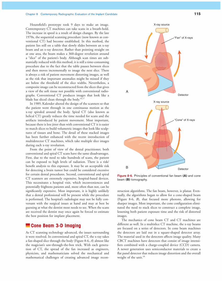
Cone Beam 3-D Imaging As CT scanning technology advanced, the issues surrounding it were resolved. In conventional and spiral CT, the x-ray takes a fan-shaped slice through the body ( Figure 8-6, A ) almost like the magician ’ s saw-through-the-box trick. With each genera-tion of CT, the spread of the fan increased as engineers, physicists, and mathematicians solved the mechanical and mathematical challenges of creating advanced image recon-
Figure 8-6. Principles of conventional fan beam (A) and cone beam (B) tomography.
X-ray source
“Fan” of X-rays
X-ray source
Detector
Detector
A
B
“Cone” of X-rays
struction algorithms. The fan beam, however, is planar. Even-tually, the algorithms began to allow for a cone-shaped beam ( Figure 8-6, B ), that focused more photons, allowing for sharper images. Most important, the cone confi guration elimi-nated the need to stack slices to construct a complete image, lessening both patient exposure time and the risk of distorted images.
The mechanics of cone beam CT and CT machines are different as well. In a multislice CT machine, the x-ray beams are focused on a series of detectors. In cone beam machines the detectors are laid out in a square-shaped detector array. The material used in the detectors affects image quality. Many CBCT machines have detectors that consist of image intensi-fi ers combined with a charge-coupled device (CCD) camera. A newer generation uses semiconductor materials to create a fl at panel detector that reduces image distortion and the overall weight of the unit. 18
116 Chapter 8 Contemporary Radiographic Evaluation of the Implant Candidate
In 1982 Richard Robb, a biophysicist and computer scien-tist at the Mayo Clinic, developed the fi rst CBCT machine. 19 It was used primarily for angiography. The technology was refi ned over the next two decades, and in 1998 Mozzo et al. published an article in European Radiology in which they described a machine that for the fi rst time used the cone beam technique specifi cally for “ dento-maxillo-facial imaging. ” 20
The cone beam confi guration is ideal for the maxillofacial region because the dimensions of the beam allow for a pan-oramic view, sparing patients the radiation exposure of sepa-rate scans of the maxilla and mandible. In dental applications, cone beam CT images may be more accurate than hospital CT scans taken of the head and neck region. In fact, as a profes-sional side note, their accuracy may help further the growing trend to view dentistry as a whole-body profession. With CBCT scans, it is possible to detect certain types of tumors or pathology that would have gone unnoticed by conventional radiography. Dentists who are interested in this technology should avail themselves of opportunities to learn more about the interpretation of head and neck CT scans. Dental profes-sionals are not expected to be able to interpret CBCT informa-tion at the level of a medical radiologist, but dentists should be aware — and should make their patients aware — that these fi lms can easily be read and interpreted by medical radiologists if necessary.
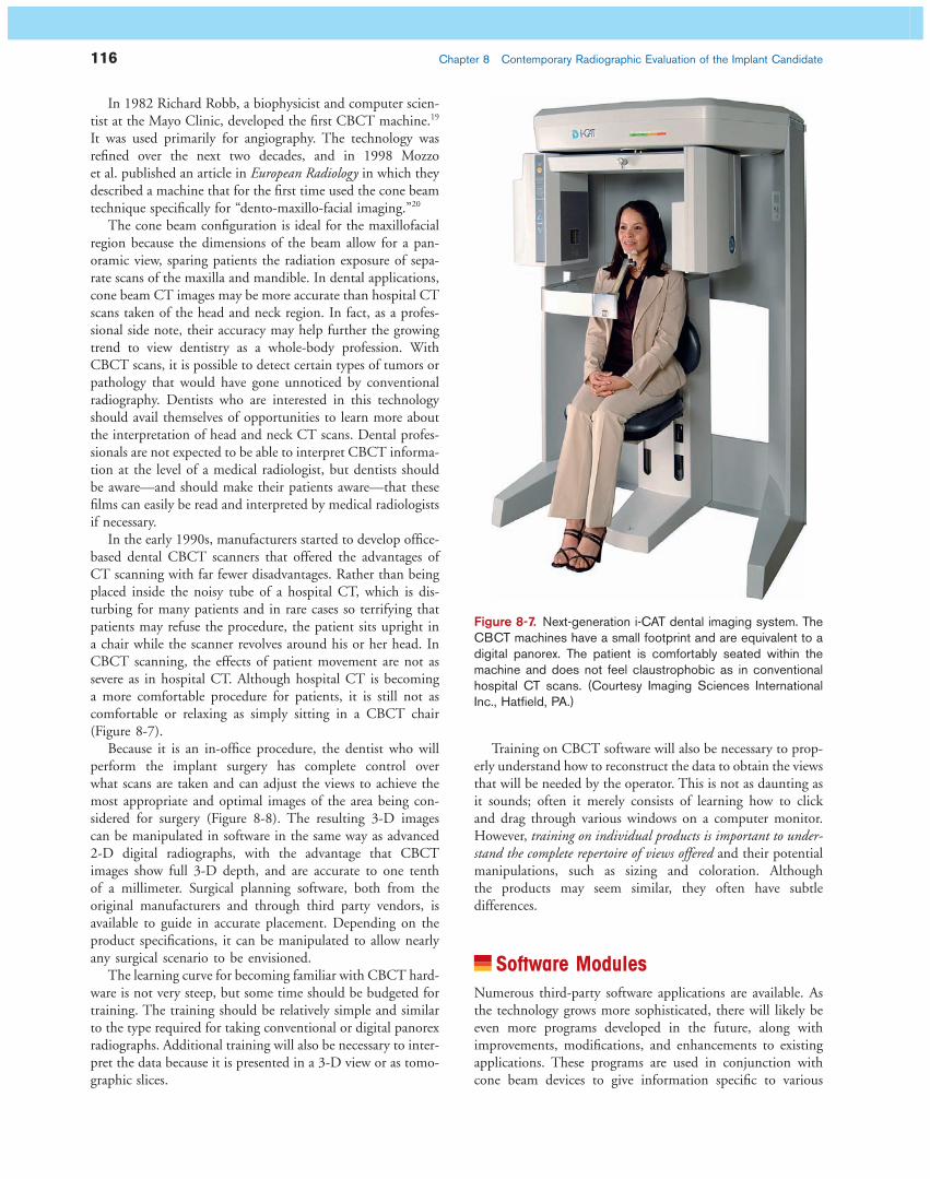
In the early 1990s, manufacturers started to develop offi ce-based dental CBCT scanners that offered the advantages of CT scanning with far fewer disadvantages. Rather than being placed inside the noisy tube of a hospital CT, which is dis-turbing for many patients and in rare cases so terrifying that patients may refuse the procedure, the patient sits upright in a chair while the scanner revolves around his or her head. In CBCT scanning, the effects of patient movement are not as severe as in hospital CT. Although hospital CT is becoming a more comfortable procedure for patients, it is still not as comfortable or relaxing as simply sitting in a CBCT chair ( Figure 8-7 ).
Because it is an in-offi ce procedure, the dentist who will perform the implant surgery has complete control over what scans are taken and can adjust the views to achieve the most appropriate and optimal images of the area being con-sidered for surgery ( Figure 8-8 ). The resulting 3-D images can be manipulated in software in the same way as advanced 2-D digital radiographs, with the advantage that CBCT images show full 3-D depth, and are accurate to one tenth of a millimeter. Surgical planning software, both from the original manufacturers and through third party vendors, is available to guide in accurate placement. Depending on the product specifi cations, it can be manipulated to allow nearly any surgical scenario to be envisioned.
The learning curve for becoming familiar with CBCT hard-ware is not very steep, but some time should be budgeted for training. The training should be relatively simple and similar to the type required for taking conventional or digital panorex radiographs. Additional training will also be necessary to inter-pret the data because it is presented in a 3-D view or as tomo-graphic slices.
Training on CBCT software will also be necessary to prop-erly understand how to reconstruct the data to obtain the views that will be needed by the operator. This is not as daunting as it sounds; often it merely consists of learning how to click and drag through various windows on a computer monitor. However, training on individual products is important to under-stand the complete repertoire of views offered and their potential manipulations, such as sizing and coloration. Although the products may seem similar, they often have subtle differences.
Software Modules Numerous third-party software applications are available. As the technology grows more sophisticated, there will likely be even more programs developed in the future, along with improvements, modifi cations, and enhancements to existing applications. These programs are used in conjunction with cone beam devices to give information specifi c to various
Figure 8-7. Next-generation i-CAT dental imaging system. The CBCT machines have a small footprint and are equivalent to a digital panorex. The patient is comfortably seated within the machine and does not feel claustrophobic as in conventional hospital CT scans. (Courtesy Imaging Sciences International Inc., Hatfi eld, PA.)

Chapter 8 Contemporary Radiographic Evaluation of the Implant Candidate 117
procedures. They provide opportunities to do procedures in a minimally invasive way, allowing the optimization of existing bone and minimizing the need for bone grafting. They also can help indicate which approaches are not appropriate.
This is a general overview of their offerings. Chapter 18 goes into more detail. In addition, check websites for the most up-to-date information on what services they provide.
Fabrication Software Vendors such as Biomedical Modeling Inc. ([BMi] Boston, MA, www.biomodel.com/index.html ) and Keystone Dental (Burlington MA, www.keystonedental.com ) produce virtual and/or tactile maxillofacial models from CT data ( Fig. 8-9 ). They can be colorized to highlight selected features such as the inferior alveolar nerve. These life-size, three-dimensional rep-licas of the patient ’ s anatomy are especially useful for rehears-ing complicated procedures and in situations in which several
specialists may be involved in surgical planning. They can also be used as teaching references for patients and students. Although they may be considered overkill for routine implants, their use can bring to light unanticipated problems before surgery, reducing operating time and potential complications. In bone-grafting and augmentation procedures, the prototypes allow visualization of the actual defects before operations, for exact planning of augmentation or donor sites to make them conducive for future implant placement.
Surgical Planning Software Several vendors, including the prototype companies, offer sur-gical planning software and custom drill guides that precisely align implant placement. The software offers detailed, three-dimensional views of the patient ’ s anatomy, which often can be custom-colored to guide in planning, allowing a dentist to safely rehearse a procedure and consider solutions to potential
Figure 8-8. A, Cross-sectional images of an atrophic maxilla. A panoramic radiograph could not provide such information. B, Ridge augmentation surgery. C, Postoperative cross-sectional images of the ridge augmentation after completion of the ridge augmentation surgery.
A
B
C

118 Chapter 8 Contemporary Radiographic Evaluation of the Implant Candidate
A B
C D
Figure 8-9. A and B, Life-size stereolithic models, produced using CBCT imaging data, assist in accurate preplanning procedures and manipulations. C and D, A surgical guide prepared with CBCT-obtained data allow for accurate implant placement and fl apless surgery. ( A and B, Courtesy Biomedi-cal Modeling Inc., Boston, MA. C and D, Keystone Dental, Burlington, MA.)
• Medical Modeling, www.medicalmodeling.com/fl ashsite/splash.html
• Nobel Biocare, www.nobelbiocare.com
The Advantages and Disadvantages of Digital Files Digital 2-D radiographs and 3-D cone beam images have the advantages — and disadvantages — of computer fi les. They can be sent to colleagues over computer networks to enable col-laboration and consultation. Before doing so, dentists must check with local, state, and federal regulations about patient confi dentiality — it may be necessary to encrypt the fi les or
complications ( Figs. 8-10 to 8-12 ). The benefi ts of rehearsing with tactile, life-size surgical prototypes cannot be overesti-mated for challenging cases, and for more routine cases surgical planning software will provide the necessary level of detail, including tissue depth and density. It should be noted, however, that prototypes may reveal unanticipated complications.
The following is a representative list of vendors. Check with CBCT manufacturers to determine which vendors ’ programs are compatible with their units.
• Dolphin Imaging, www.dolphinimaging.com • iDent, www.ident-surgical.com/default.htm • BioHorizons, www.biohorizons.com • Keystone Dental, www.keystonedental.com

Chapter 8 Contemporary Radiographic Evaluation of the Implant Candidate 119
Figure 8-10. A sample of the types of views offered by software modules. Most have settings to customize contrast and to select only the area of interest. (Courtesy Imaging Sciences International Inc., Hatfi eld, PA.)
A
B
use virtual private networks (VPNs) rather than sending the fi les over the public Internet. Files can also be damaged or destroyed, and should always be backed up both within the dental suite and at an off-site storage facility. Most important, dentists and technicians must create a protocol and labeling system to ensure that records are not accidentally overwritten.
Note on Radiation The effects of radiation are of concern to patients and provid-ers. 21 Years ago, dentists and dental assistants were at risk from
squamous cell carcinoma if they held conventional fi lms in place while radiographs were being taken. 22 Today, the opera-tor of a cone beam unit stands away from any x-ray fi eld, as would an operator taking a typical panoramic radiograph.
Although the dangers of radiation exposure must always be respected, concerned patients may make an apples/oranges comparison between dental cone beam x-rays and medical CT scans, which generally take longer and image greater amounts of tissue and bone. As Table 8-1 of the proprietary i-CAT Cone Beam 3-D Dental Imaging System from Imaging Sci-ences International shows, depending on the unit, the amount of radiation exposure during a cone beam scan can be more
120 Chapter 8 Contemporary Radiographic Evaluation of the Implant Candidate
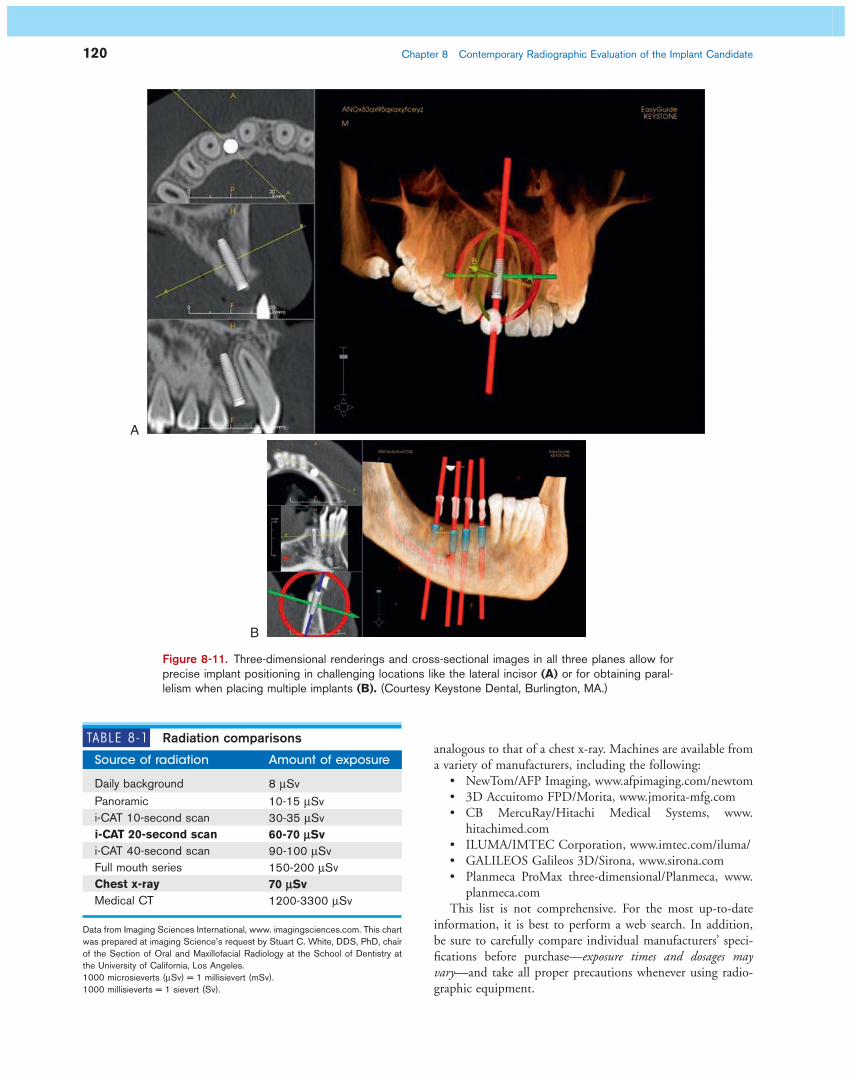
A
B
Figure 8-11. Three-dimensional renderings and cross-sectional images in all three planes allow for precise implant positioning in challenging locations like the lateral incisor (A) or for obtaining paral-lelism when placing multiple implants (B). (Courtesy Keystone Dental, Burlington, MA.)
TABLE 8-1 Radiation comparisons
Source of radiation Amount of exposure
Daily background 8 μ Sv Panoramic 10-15 μ Sv i-CAT 10-second scan 30-35 μ Sv i-CAT 20-second scan 60-70 μ Sv i-CAT 40-second scan 90-100 μ Sv Full mouth series 150-200 μ Sv Chest x-ray 70 μ Sv Medical CT 1200-3300 μ Sv
1000 microsieverts ( μ Sv) = 1 millisievert (mSv). 1000 millisieverts = 1 sievert (Sv).
Data from Imaging Sciences International, www. imagingsciences.com . This chart was prepared at imaging Science ’ s request by Stuart C. White, DDS, PhD, chair of the Section of Oral and Maxillofacial Radiology at the School of Dentistry at the University of California, Los Angeles.
analogous to that of a chest x-ray. Machines are available from a variety of manufacturers, including the following:
• NewTom/AFP Imaging, www.afpimaging.com/newtom • 3D Accuitomo FPD/Morita, www.jmorita-mfg.com • CB MercuRay/Hitachi Medical Systems, www.
hitachimed.com • ILUMA/IMTEC Corporation, www.imtec.com/iluma/ • GALILEOS Galileos 3D/Sirona, www.sirona.com • Planmeca ProMax three-dimensional/Planmeca, www.
planmeca.com This list is not comprehensive. For the most up-to-date
information, it is best to perform a web search. In addition, be sure to carefully compare individual manufacturers ’ speci-fi cations before purchase — exposure times and dosages may vary — and take all proper precautions whenever using radio-graphic equipment.

Chapter 8 Contemporary Radiographic Evaluation of the Implant Candidate 121
Figure 8-12. A, Software such as i-CAT Vision allows for three-dimensional viewing of the area of interest, as in this case where an implant was placed in #14. Multiple views allow for visualization of the area from a variety of viewpoints ( clockwise from top left : axial view, panoramic view, cross-sectional views, and 3-D rendering). B, Cross-sections of the anterior maxilla. Note the clear visibility of the incisive canal, which is diffi cult to visualize in conventional panoramic x-rays due to superim-position of adjacent structures. (Courtesy Imaging Sciences International Inc., Hatfi eld, PA.)
A
B
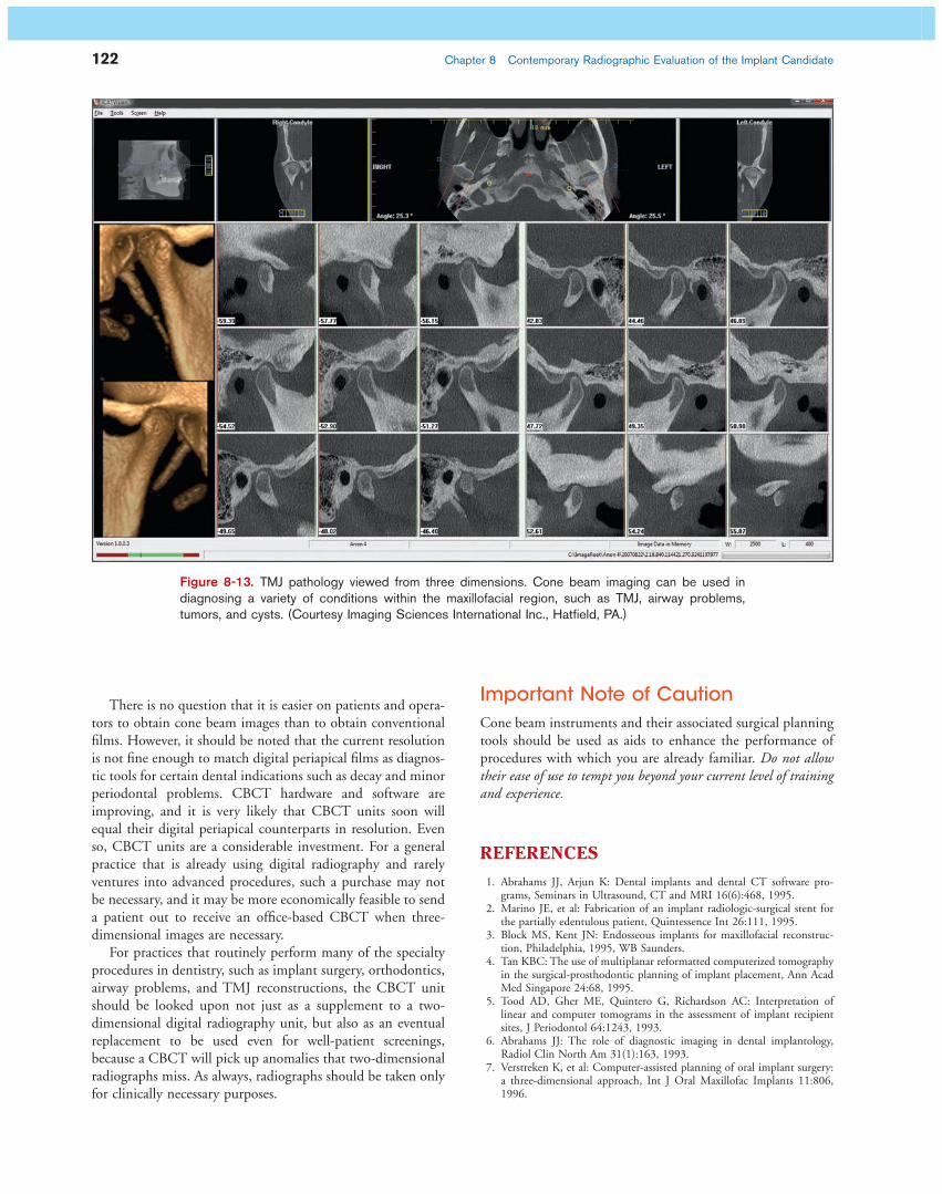
Additional Diagnostic Benefi ts Beyond Implant Placement Although this chapter specifi cally discusses implant proce-dures, there are other associative problems that cone beam can assist in diagnosing, such as temporomandibular joint (TMJ) conditions ( Figure 8-13 ), airway problems, impacted teeth, and anatomical anomalies. As the technology continues to improve, it also may be able to visualize dental disease and decay and periodontal disease more easily. This method of
diagnosis looks to become the only fi lm that may be required to treat most oral-maxillofacial problems.
If a practice has not yet switched to two-dimensional digital radiography, the investment in a cone beam unit may be amortized by using it for routine radiographic screen-ing as well as for advanced procedures. A typical CBCT unit ’ s dimensions are similar to a conventional panorex in size and footprint, and should fi t comfortably within existing dental suites. Manufacturers offer training to dentists and dental technicians.
122 Chapter 8 Contemporary Radiographic Evaluation of the Implant Candidate
There is no question that it is easier on patients and opera-tors to obtain cone beam images than to obtain conventional fi lms. However, it should be noted that the current resolution is not fi ne enough to match digital periapical fi lms as diagnos-tic tools for certain dental indications such as decay and minor periodontal problems. CBCT hardware and software are improving, and it is very likely that CBCT units soon will equal their digital periapical counterparts in resolution. Even so, CBCT units are a considerable investment. For a general practice that is already using digital radiography and rarely ventures into advanced procedures, such a purchase may not be necessary, and it may be more economically feasible to send a patient out to receive an offi ce-based CBCT when three-dimensional images are necessary.
For practices that routinely perform many of the specialty procedures in dentistry, such as implant surgery, orthodontics, airway problems, and TMJ reconstructions, the CBCT unit should be looked upon not just as a supplement to a two-dimensional digital radiography unit, but also as an eventual replacement to be used even for well-patient screenings, because a CBCT will pick up anomalies that two-dimensional radiographs miss. As always, radiographs should be taken only for clinically necessary purposes.
Figure 8-13. TMJ pathology viewed from three dimensions. Cone beam imaging can be used in diagnosing a variety of conditions within the maxillofacial region, such as TMJ, airway problems, tumors, and cysts. (Courtesy Imaging Sciences International Inc., Hatfi eld, PA.)
Important Note of Caution Cone beam instruments and their associated surgical planning tools should be used as aids to enhance the performance of procedures with which you are already familiar. Do not allow their ease of use to tempt you beyond your current level of training and experience.
REFERENCES
1. Abrahams JJ , Arjun K : Dental implants and dental CT software pro-grams, Seminars in Ultrasound , CT and MRI 16 ( 6 ): 468 , 1995 .
2. Marino JE , et al : Fabrication of an implant radiologic-surgical stent for the partially edentulous patient , Quintessence Int 26 : 111 , 1995 .
3. Block MS , Kent JN : Endosseous implants for maxillofacial reconstruc-tion , Philadelphia , 1995 , WB Saunders .
4. Tan KBC : The use of multiplanar reformatted computerized tomography in the surgical-prosthodontic planning of implant placement , Ann Acad Med Singapore 24 : 68 , 1995 .
5. Tood AD , Gher ME , Quintero G , Richardson AC : Interpretation of linear and computer tomograms in the assessment of implant recipient sites , J Periodontol 64 : 1243 , 1993 .
6. Abrahams JJ : The role of diagnostic imaging in dental implantology , Radiol Clin North Am 31 ( 1 ): 163 , 1993 .
7. Verstreken K , et al : Computer-assisted planning of oral implant surgery: a three-dimensional approach , Int J Oral Maxillofac Implants 11 : 806 , 1996 .
Chapter 8 Contemporary Radiographic Evaluation of the Implant Candidate 123
8. Stellino G , Morgano SM , Imbelloni A : A dual-purpose, implant stent made from a provisional fi xed partial denture , J Prosthet Dent 74 ( 2 ): 212 , 1995 .
9. Klein M , Cranin AN , Sirakian A : A computerized tomography (CT) scan appliance for optimal presurgical and preprosthetic planning of the implant patient , Pract Periodont Aesthet Dent 5 ( 6 ): 39 , 1993 .
10. Petrik V , Apok V , Britton JA , et al : Godfrey Hounsfi eld and the dawn of computed tomography , Neurosurgery 58 ( 4 ): 780 - 787 , 2006 Apr ; dis-cussion 780-787 .
11. Webb S : Historical experiments predating commercially available com-puted tomography , Br J Radiol 65 ( 777 ): 835 - 837 , Sep 1992 .
12. http://nobelprize.org/nobel_prizes/medicine/laureates/1979/perspectives.html .
13. http://www.whittington.nhs.uk/default.asp?c=2804&t=1 . 14. Kalender W : Computed tomography: Fundamentals, system technology,
image quality, applications , Erlangen, Germany , 2005 , Wiley-VCH . 15. Bushberg JT , et al : The Essential Physics of Medical Imaging , Philadel-
phia , 2002 , Lippincott Williams & Wilkins .
16. Powsner R , Powsner E : Essential Nuclear Medicine Physics , Malden , 2006 , Wiley-Blackwell .
17. Armstrong P , et al : Diagnostic Imaging , Malden , 2004 , Blackwell . 18. Sukovic, P: Cone Beam Computed Tomography in Dentomaxillofacial
Imaging, AADMRT Newsletter, Winter 2004. 19. Robb , RA : Dynamic Spatial Reconstructor: An X-ray Video Fluoroscopic
CT scanner for dynamic volume imaging of moving organs , IEEE Trans Med Im MI-1 ( 1 ): 22 - 23 , 1982 .
20. Mozzo P , Procacci C , Tacconi A , et al : A new volumetric CT machine for dental imaging based on the cone-beam technique: preliminary results , Eur Radiol 8 : 1558 - 1564 , 1998 .
21. Brenner D , Hall , E : Computed Tomography (CT) — An Increasing Source of Radiation Exposure , N Eng J Med 357 ( 22 ): 2277 - 2278 , Nov 29 2007 .
22. Langland OE , et al . Principles of dental imaging , Baltimore , 2002 , Lippincott Williams & Wilkins .