content area: general structures - · pdf filecontent area: general structures building design...
TRANSCRIPT

CONTENT AREA: GENERAL STRUCTURES
Building DesignVocabulary:
• Force: the push or pull exerted on an object, including its magnitude, direction, and point of application
• Collinear forces: vectors lie along the same straight line• Concurrent forces: lines of action meeting at common point• Non concurrent forces: lines of action do not pass through a common point• Coplanar forces: lines of action all lie within the same plane • Structural forces: any combination of forces (e.g.: truss is sets of concurrent coplanar
forces)• Load (p): a force applied to a body (also called an external force) • Stress (f): the resistance of a body to a load (also called an internal force) and
measured in kips (K)• Unit Stress: stress/unit of area at the section, measured in psi or ksi (kips/sq.in.)• Allowable Stress: maximum permissible unit stress• Factor of Safety: ratio of the ultimate strength of material to its working stress• Strain: the deformation of a material caused by external loads. Tensile loads stretch,
and compressive loads shorten.• Shear: a strain produced by pressure in the structure when its layers are lateral shifted
in relation to each other• Moment: the tendency of a force to cause rotation about a given point or axis• Modulus of Elasticity: a material’s resistance to non permanent (or elastic)
deformation • Reaction: the force acting at the supports of a beam that holds it in equilibrium • Eccentric Load: A load imposed on a structural member at some point other than the
centroid of the section• Truss: framework consisting of rafters, posts, and struts• Moment of Inertia: measure of an object’s resistance to changes to its rotation. • Section Modulus: is the ratio of a cross section's second moment of area to the
distance of the extreme compressive fibre from the neutral axis• Deflection: the displacement of a structural element under a load• Hook’s Law: unit stress is proportional to unit strain up to the elastic limit• Yield Point: the amount of stress that causes a material to deform without additional
load added• Composite Structural Member: more than one material working together (eg:
reinforced concrete, box beam, flitch beam)• Resilience: ability of material to absorb energy while undergoing elastic range
stresses• Ductility: ability of a material to absorb energy prior to fracture...toughness!
Equations: (MEMORIZE THOSE IN PURPLE) • Equilibrium: ∑M = 0; ∑V = 0; ∑H = 0• Stress (f) = Total Force (P) / Area (A) f = P/A • Force Equations {units = kips or lbs}
• To find force " " Force (F) = Mass (M) x Acceleration (a)" F = Ma
page 1 of 63 :: created 06.2012 :: are 4.0 :: organized by twitter/areforum member @jennypdx
AREndurance STUDY NOTES
structural systems

!• To find shear diagram shear force
" " Shear Resisting Force (R) = (V) = uniform load per foot (w) x distance (L) / 2" " " R = V = wL / 2
• To find the horizontal force on a retaining wall" " Force (F) = soil pressure (w) x height of wall (h)2 / 2 " F = w2h / 2
• Moment Equations {units = kip ft, lb ft, kip in, or lb in}• To find equilibrium by taking moments about a point:" " Moment (M) = Force (P) x distance (d)" M = Pd• To find the eccentric load (the same as finding equilibrium)
" " Moment (M) = Force (P) x eccentricity (e)" M = Pe• To find uniform load" " Moment (M) = uniform load (w) x length (L)2 / 8" M = wL2 / 8• To find point/concentrated load at the center of a member:" " Moment (M) = Point Load (P) x length (L) / 4" M = PL / 4• To combine Point Load and Uniform Loads:! M = wL2 / 8 + PL / 4
• Section Modulus Equations {units = inch3}• To find Section Modulus (both moment and stress are in kips or lbs)" " Section Modulus (S) = Base (b) x diameter (d)2 / 6" S = bd2 / 6" " Section Modulus (S) = Moment (M) / Bending Stress (Fb)" S = M / Fb
! ! Section Modulus (S) = Moment of Inertia / given constant (c)" S = I / c• To find Section Modulus for a roof beam" " Section Modulus (S) = Moment (M) / 1.25 x Bending Stress (Fb)"S = M / 1.25Fb
• Moment of Inertia Equations {units = inch4}• To find Moment of Inertia (occurs about the centroidal axis)" " Moment of Inertia (I) = Base (b) x depth (d)3 /12" I = bd3 / 12! ! Rectangle Moment of Inertia (I) = Base (b) x depth (d)3/ 3" I = bd3 / 3! ! Moment of Inertia at base (Ibase) = Moment of Inertia (I) + " " Area (A) x distance from centroid to base (y)2" Ibase = I + Ay2
• Stress Equations {units = ksi or psi}• To find bending stress (max bending stress occurs at the extreme fibers)" " Bending Stress (fb) = Moment (M) / Section Modulus (S)" fb = M / S! ! Bending Stress (fb) = Moment (M) x constant (c) / Moment of Inertia (I)" " (so…the greater the c, the greater the bending stress!)" fb = Mc / I• To find axial stress (max axial stress occurs along entire cross section)
" " Axial Tension or Compression Stress (fa) = Axial Tension (P) / Area (A) (axial stress is the same as both tension and compression!)" Fa = P / A
• To find shear stress (max shear stress occurs at the neutral axis and is the same at both the vertical and horizontal axis)
" " Shear Stress (fv) = 1.5 x Shear Force (V) / Area (A)" fv = 1.5V / A" " Shear Stress (fv) = Shear Force (V) x Neutral Axis of area above plane (Q) / " " Moment of Inertia (I) x width of beam (b)" fv = VQ / Ib
Neutral axis of area above Plane (Q) = section area (A) x distance from " centroid of rectangle to centroid of section above neutral axis (d) " Q = Ad
• Modulus of Elasticity Equation " " Modulus of Elasticity (E) = Stress (f) / Strain (ε)" E = f / ε
page 2 of 63 :: created 06.2012 :: are 4.0 :: organized by twitter/areforum member @jennypdx
AREndurance STUDY NOTES
structural systems
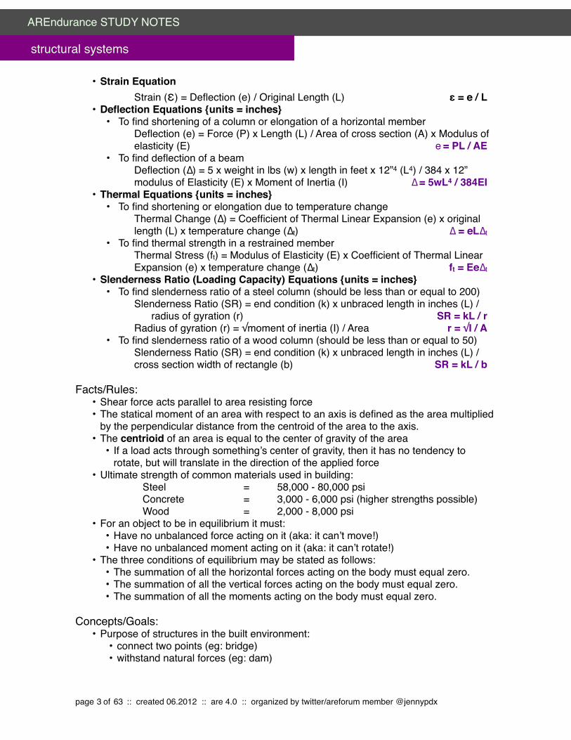
• Strain Equation " " Strain (ε) = Deflection (e) / Original Length (L)" ε = e / L
• Deflection Equations {units = inches}• To find shortening of a column or elongation of a horizontal member
Deflection (e) = Force (P) x Length (L) / Area of cross section (A) x Modulus of elasticity (E)" e = PL / AE
• To find deflection of a beamDeflection (∆) = 5 x weight in lbs (w) x length in feet x 12”4 (L4) / 384 x 12” modulus of Elasticity (E) x Moment of Inertia (I)" ∆ = 5wL4 / 384EI
• Thermal Equations {units = inches}• To find shortening or elongation due to temperature change
Thermal Change (∆) = Coefficient of Thermal Linear Expansion (e) x original length (L) x temperature change (∆t)" ∆ = eL∆t
• To find thermal strength in a restrained member Thermal Stress (ft) = Modulus of Elasticity (E) x Coefficient of Thermal Linear Expansion (e) x temperature change (∆t)" ft = Ee∆t
• Slenderness Ratio (Loading Capacity) Equations {units = inches}• To find slenderness ratio of a steel column (should be less than or equal to 200)
Slenderness Ratio (SR) = end condition (k) x unbraced length in inches (L) / radius of gyration (r)" SR = kL / rRadius of gyration (r) = √moment of inertia (I) / Area ! r = √I / A
• To find slenderness ratio of a wood column (should be less than or equal to 50) Slenderness Ratio (SR) = end condition (k) x unbraced length in inches (L) / cross section width of rectangle (b)" SR = kL / b
Facts/Rules:• Shear force acts parallel to area resisting force• The statical moment of an area with respect to an axis is defined as the area multiplied
by the perpendicular distance from the centroid of the area to the axis. • The centrioid of an area is equal to the center of gravity of the area
• If a load acts through something’s center of gravity, then it has no tendency to rotate, but will translate in the direction of the applied force
• Ultimate strength of common materials used in building: " " Steel " " " =" 58,000 - 80,000 psi " " Concrete" " =" 3,000 - 6,000 psi (higher strengths possible)" " Wood" " " =" 2,000 - 8,000 psi
• For an object to be in equilibrium it must:• Have no unbalanced force acting on it (aka: it can’t move!)• Have no unbalanced moment acting on it (aka: it can’t rotate!)
• The three conditions of equilibrium may be stated as follows: • The summation of all the horizontal forces acting on the body must equal zero. • The summation of all the vertical forces acting on the body must equal zero. "• The summation of all the moments acting on the body must equal zero.
Concepts/Goals:• Purpose of structures in the built environment:
• connect two points (eg: bridge)• withstand natural forces (eg: dam)
page 3 of 63 :: created 06.2012 :: are 4.0 :: organized by twitter/areforum member @jennypdx
AREndurance STUDY NOTES
structural systems

• span and enclose space (eg: building)• Structure is a 3-D art form, like sculpture, but it exists with a purpose• Most structural failures are during construction• Purpose of structural design:
• Resolution of the conflict between the vertical direction of most load forces and the horizontal dynamics of mankind (eg: gravity and the way we work)
• All structures will be destroyed eventually• Many structural failures are caused by improper load assumptions.• Most concerning types of stress in building design and construction are tension,
compression and shear• Forces (or Loads) on Architectural Structures:
• External (applied) loads: cause primary stresses. • Vertical forces are comprised of:
• Dead loads : Live Loads• Static : Dynamic• Concentrated: Distributed
• Vertical loads are mostly caused by gravity• People (which are both static and dynamic)• Moveable equipment• Vehicles• Rain, Snow, Drifting Snow• Ponding• Buoyancy• Construction Materials (bricks, stockpile, materials, etc)• Dead loads are permanently fixed in a structure, and easier to predict• Live loads move around on their own, or can be moved, and cause vibration.
• They are hard to predict and require a higher safety precaution• Produce changing deformations, and are either:• Dynamic: the load changes with respect to time, often suddenly (eg:
earthquakes, wind)• Static: the load moves with building accumulation, slowly.• Example: walking in a classroom is static, siting in a chair is dynamic
• Horizontal forces are comprised of:• Forces with horizontal components (SEE: LATERAL FORCES)• Wind: hurricanes, tornados (no warning or unpredicted)• Ice: Expansion force (as it freezes), footings below frost lines• Earthquakes: (the biggest concern, and hardest to design for, the best we can
do is have good warning systems) Effects of earthquakes are:• ground rupture (in the fault zone)• ground failure (sliding, settlement, liquefaction)• tsunami (seismic sea waves, called a "seich" on inland bodies of water)• ground shaking (vibration, repetitive dynamic motion)
• People: pushing on a window, balcony, etc• Vehicles: impact loads (collisions), sudden starts and stops• Machinery: generators, oscillating equipment, vibration of equipment• Earth or Water: pressure on below grade structure• Transportation and Erection: (in transport to site and put in place)• Lighting: powerful • Blast: explosions
page 4 of 63 :: created 06.2012 :: are 4.0 :: organized by twitter/areforum member @jennypdx
AREndurance STUDY NOTES
structural systems

• Internal Forces: cause secondary stresses which can be greater than primary stresses• The result of system or material characteristics • Movements (if resisted) are elastic (temporary) or inelastic (permanent) strains.• Shrinkage: some takes place early (eg: concrete)• Humidity Changes (eg: wood)• Thermal Changes (eg: steel, metal, thin shell)• Fabrication Errors (eg: incomplete concrete pour)• Prestressing (they're all the same)
• Deconstructive Agents: reduce capacity of structural element • Fire: the biggest issue! Heavy timber construction is the most preventative form.• Chemical corrosion: parking lots are the worst.• Erosion: wind/water• Insects/Plants/Animals
• Materials and Systems: What do we require of a structural material and of a structural system:
• Strength = resist the three stresses (tension, compression, shear)• Tension: the most efficient system we do
Primary deformation "= " elongation (e)Failure mode "" = " tearing
• Compression: Primary deformation "= " shorteningFailure mode "" = " crushing (strength related)" " " " buckling (stiffness related)Cross section will bulge
• Shear: Primary deformation "= " change in angleFailure mode "" = " torsion
• (also Bending:Primary deformation "= " deflection)
• Stiffness = resist deformation• Elastic response is temporary• Ineleastic response is permanent• Want deformation to be:
• predictable: calculate what happened• small: high resistance• temporary: go away when the load is off
• Stability• Durability
• The line of action is parallel to and in line with the force. • If lines of action of several forces pass through a common point, forces are
concurrent• If the lines of action don’t pass through a common point, the forces are non-
concurrent• The point is called the center of moments or axis of rotation and the distance,
called the moment arm or lever arm, is measured in a direction perpendicular to the line of action of the force
• A force equal in magnitude to the resultant, but opposite in direction and on the same line of action as the resultant is called the equilibrant !
page 5 of 63 :: created 06.2012 :: are 4.0 :: organized by twitter/areforum member @jennypdx
AREndurance STUDY NOTES
structural systems

• It is sometimes convenient in the analysis of structure to replace one force with two or more other forces that will produce the same effect on a body as the original force.• These forces are called components of the original force, and the procedure is
called resolving forces• Two forces equal in magnitude, but opposite in direction, and acting at some distance
from each other form a couple • The higher the strength, the less ductile and more brittle it is (so we're lucky our
bones are surrounded by tissue)• Temperature will alter the strength...looses modulus of elasticity...not good!• Heat used to melt and shape a member, but once it is shaped, stiffness will still be
altered• Charpy V-Notch Test:
• A ductility test where a piece of material has a v-notch cut into the to top• Tests how much energy it takes to make the notch go through the whole piece• If it breaks quickly with not much energy, then the material is brittle• If it breaks slowly and takes a lot of energy, then it is ductile
• Direct Stress Problems:• F = P/A is an investigative formula• St. Venant's Principle for Direct Stress:
• The stresses and strains in a body at points that are sufficiently remote from points of application of load depends only on the static resultant of the loads and not on the distribution of loads.
• 9 Assumptions for this principle to be satisfied:• The thing being loaded must be perfectly straight• Load must be applied axially (ie: the center of gravity at the cross section)• Cross section of the thing being loaded must be constant• Cross section under investigation has to be some distance away from the
support/loaded ends• Loaded member must be made of a single material• Material must be homogenous (and strong, no soft spots!)• Load must be statically loaded• Elastic range stresses (don't go past yield stress!)• Loading must be pure tension, compression, or shear (no secondary effects)
Processes:• Three general steps in structural design:
• Determine the loads (compute)• Calculate the stresses (analyze)• Dimension and proportion the members and detail the connections such that the
stresses are within the limits for the structural materials (design)
! Finding Equilibrium" Objects that are at rest are at static equilibrium " Three equations of static equilibrium"" " Horizontal Translational Equilibrium Equation:" " " Sum of all forces parallel to the x axis = ΣFx = 0" " " " won't move left or right" " " " relative to the ground" " " Sum of all forces parallel to the y axis = ΣFy = 0
page 6 of 63 :: created 06.2012 :: are 4.0 :: organized by twitter/areforum member @jennypdx
AREndurance STUDY NOTES
structural systems

" " " " won't move up or down" " " " relative to the universe" " " ΣFx = ΣFy = 0 is not enough to ensure equilibrium!" " Rotational Equilibrium Equation" " " ΣMz = 0! Solving A Direct Stress Problem:" 1. Determine which equation to use " " f = P/A " or " P = AFallowable " or " A = P/Fallowable"" 2. Find the cross section of the area of the form" 3. Figure out the stress " " f = P/A" 4. Is it safe? What's the allowable stress we can use? Check the following:" " Structural Steel Allowable Tension" " " " " 22,000 psi" " Concrete usable compression in bearing" " " " 900 psi" " Structural Lumber (doug fir) compression parallel to grain" " 1,150 psi
" Solving a Direct Shear Problem:" 1. Determine which equation to use" " f = P/A " or " P = AFallowable " or " A = P/Fallowable"" 2. Find the area of the bolts" " A = (# of bots) x (πr²) " 3. Find allowable stress" " Pallowable = A x Fallowable
Statics and Forces in a Nutshell
Forces are also known as loads. They are an action that has direction (an arrowhead that indicates if it points or pulls), magnitude (pounds or kips), and line of action (a given angle in degrees).
When a bunch of forces are acting on the same point, it is called the resultant, and it has the same effect as all of the individual forces combined.
Resultants are calculated by simple algebra when all of the magnitudes and lines of action are known. First, resolve the forces into individual vertical and horizontal components using A2 + B2 = C2 and/or SohCahToa.
The sum of all of the vertical components gives the vertical component of the resultant, and the sum of all of the horizontal components gives the horizontal component of the resultant.
When a force touches a member, the member becomes stressed and it tries to internally resist the external force.
Stresses can be compression (shorten or crush the member), tension (stretch the member), or shear (two members slide past each other)
The amount of stress (f) is calculated by taking all of the force that is touching the material (P) and dividing it by the area that it touches (A) (f = P/A)
page 7 of 63 :: created 06.2012 :: are 4.0 :: organized by twitter/areforum member @jennypdx
AREndurance STUDY NOTES
structural systems

Stressed members can't always resist external forces. Strain is the change in size, aka deformation, of a member caused by the forces acting on it.
The amount of strain in a unit (ε) is actually a ratio of the total deformation (e) to the original length of the member (L) (ε = e/L)
Strain is proportional to the amount of stress applied…but only up to a certain point, which depends on the type of material. that point is called the elastic limit.
Once the elastic limit is reached, the material which change length at a faster ratio than the applied force until it gets to the yield point.
The yield point is when the material continues to deform with little to no load applied. It's the point of no return…because after that the material will rupture once it hits its ultimate strength.
Materials want to put off reaching ultimate strength as long as they can, and the resistance is measured by the Modulus of Elasticity.
Resistance, or the Modulus of Elasticity (E) is therefore a ratio of the stress acting on the member (f) to the amount of strain (ε) (E = f/ε)
To make things easier for the designer, the building code lists typical Modulus of Elasticity values for most materials.
A more common calculation designers must solve is finding the total deformation of the member (e). It is a ratio of the force (P) and Length (L) to the Area (A) and Modulus of Elasticity (E) (e = PL/AE)
When force is applied to a member, it will try to cause the member to rotate around a point. This called the moment.
If the force causes a clockwise rotation, then the moment is positive. If the force causes a counter-clockwise rotation, then the moment is negative.
If a member doesn't rotate, then it means that the positive moments applied to it are equal to the negative moments. This is called equilibrium and is calculated by finding the reactions.
The reactions are usually located at each end of a member…lets say a beam. Select one of the Reactions, and use the given forces and dimensions from that reaction point. R1 = P1(L) + P2(L) - R2(L)
Then solve for the other reaction by checking equilibrium. All upward forces equal all downward forces. R2 = R1 - P1 - P2
page 8 of 63 :: created 06.2012 :: are 4.0 :: organized by twitter/areforum member @jennypdx
AREndurance STUDY NOTES
structural systems

Properties of Sections in a Nutshell
Sections are just that…a slice of a member where forces can be examined further.
The point at which the mass of a member is concentrated is called the center of gravity. The actual point at the center of gravity that measurements are taken from is called the centroid.
While the centroid is the center, it is not necessarily at the geometric center of the section. Only when a section is symmetrical (a rectangle beam for example) the center is located in the geometric center.
Calculating the centroid of a symmetrical object is a simple problem. In the case of a rectangle with base (b) and depth (d) the centroid is at b/2 and/or d/2
When the section is unsymetrical, the statistical moment is calculated with respect to a neutral axis (typically at the base of the section). It is the area (A) times the distance to center from the neutral axis (X)
Divide the section into multiple simple shapes (typically rectangles) and find the area (A) of each, and the distance from the centroid of the simple shape to the neutral axis (x). Do this for each simple shape.
Multiply the areas and the distances together for each shape, and add them together. (A1 x D1) + (A2 x D2) = ([A1 + A2] x overall distance to neutral axis X) . Then solve for X. That's the overall centroid.
While the modulus of elasticity measures how stiff a material is (through how it resists stress), the measure of bending stiffness of a section is called the Moment of Inertia.
The moment of inertia of a section about a certain axis is the sum of all the small areas of the section (bd) multiplied by the square of the distance from the axis to each of these areas (d2). Also said as: (bd3)
For rectangle sections where the neutral axis is the axis that passes through the centriod, the moment of inertia (I) = bd3/12.
When the axis is at the base of a rectangular section, the moment of inertia for a rectangle changes to (I) = bd3/3
For composite sections, find the moment of inertial of each simple section around its centroid, then transfer to a new axis, typically the centroid of the composite section.
The transferred moments of inertia of the simple sections are added to get the moment of inertia for the entire section.
Because the section's depth (d) is cubed, it has a greater bearing on the beam' resistance to bending. In other words, the bigger the depth of the beam, the stronger it is.
page 9 of 63 :: created 06.2012 :: are 4.0 :: organized by twitter/areforum member @jennypdx
AREndurance STUDY NOTES
structural systems

Building Systems and their IntegrationVocabulary:
• Post: long, sturdy piece of timber or metal set upright in the ground used to support • Beam: a member that supports loads perpendicularly to its longitudinal axis• Simple Beam: rests on a support at each end and ends are free to rotate• Cantilever Beam: supported at one end and restrained from rotation at that end• Overhanging Beam: rests on 2+ supports and has one or both ends cantilevered
beyond the support• Fixed End Beam: fixed against rotation at both ends• Frame: a structural system that supports other components of a physical construction• Truss: a framework, typically consisting of rafters, posts, and struts, supporting a roof,
bridge, or other structure• Gage line: standard dimension from corner edge of an angle to centerline of bolt holes.
depends on size of angle• Arch: a curved symmetrical structure spanning an opening and typically supporting the
weight of a bridge, roof, or wall above it.
Facts/Rules: • A concentrated load acts at one point on a beam• A distributed load acts over a length of a beam
• If the load/unit of length of the beam is constant it’s a uniformly distributed load• Simple beams, cantilever beams, and overhanging beams that rest on 2 supports
are statically determinate • Wood
• The oldest and most common system • One way structural system (load is transmitted through members in one direction)
"Type Width Spacing Spans Top/Bottom Use Advantage
Joists 2” nom 12” or 16” o.c. 20’ to 25’ Bridging supports bottom edge,sheathing holds top in place
Between beams or bearing walls
Tried and true method
I-Joist 1-3/4” to 3-1/2”
12” - 24” o.c. 8’ to 24’ 9-1/2” - 16” depth OSB webs and microllam (thick plywood) flanges connect to wall with hangers
Residential/light commercial
Efficient strl shape as shop fabrication eliminates common defects
Glulam 3-1/8”, 5-1/8”, 6-3/4”, 8-3/4”
varies 15’ to 60’ Several layers of timber bonded together with glue and connected with plates and/or bolts
Columns and beams, commercial, public
can be left exposed, can be tapered or curved
Plank/Beam Framing
4” or 6” 4’ or 6’ or 8’ 10’ to 20’ Wood decking span between beams, underside finish ceiling
Between girders or bearing walls, residential
Easy to insulate
page 10 of 63 :: created 06.2012 :: are 4.0 :: organized by twitter/areforum member @jennypdx
AREndurance STUDY NOTES
structural systems

Type Width Spacing Spans Top/Bottom Use Advantage
Truss varies 24” o.c. 24’ to 40’ 12 - 36” depth made of strand wood members connected with plates
Residential,Commercial, Public
MEP can pass thru
Box Beam Up to 30” varies 50’ Plywood panels glued & nailed to 2x4
Residential, Commercial, Public
Looks like solid timber, custom made
• Steel• Most commonly used structural material due to its high strength, availability,
adaptability, ductility (can deform and return to original shape/bends before it breaks)
• Suited for multi-floor construction due to strength and structural continuity• Beams span shorter distances of 8’ - 10’• Girders span longer distances of 25’ - 40’
• Concrete• Cast-in-place concrete: typically involves steel reinforcement (rebar), sometime
post-tensioning is used• Precast structural members: high-strength steel cables are pre-stressed/stretched
and concrete is poured on top. When concrete reaches minimum allowable strength cables are cut from formwork and compressive stresses are transferred to concrete that resists tension forces of own weight/live load
• Post-tensioned concrete: steel tendons are laid out in desired direction and concrete is poured on top. When concrete is cured tendons are tensioned and force is transferred to the concrete through end anchorages.
• Beam & Girder system: • Large girders carry intermediate beams which support a slab with spans of
15’-30’ • Easy to form and construct making it economical• Slabs can be penetrated (unlike PT slabs that have tendons)
• One Way Concrete Joist system (pan joists): • Prefab metal pan forms are used to create frame to support light/medium loads
with spans of 20’ - 30’ and depths of 1’ - 2’ • Formed with prefab metal pan forms spaced 24” – 36” apart in one direction
• Two Way Concrete Joist system:• Like One Way Joist but with beams in each direction • Typically used in rectangular bays where distance between columns is equal (or
close to) in both directions• Flat plate system:
• Basically a Two-Way slab with no supporting beams, only columns.• Reinforced slab spans in both directions directly into columns at 25’ with 6” - 12”
thickness• Typically used for light loads, short spans, when floor-floor height must be
minimized, and/or when simple under-side of slab appearance is required• Has low shear capacity and low stiffness
• Drop panel system:
page 11 of 63 :: created 06.2012 :: are 4.0 :: organized by twitter/areforum member @jennypdx
AREndurance STUDY NOTES
structural systems

• Like a Flat Plate system, but the slab thickness is increased around the columns for greater shear failure resistance.
• Used with greater live loads or larger spans. • Flat slab system:
• A two way slab with column capitals, drop panels, or both with spans of 30’• Waffle slab system:
• Ribs formed with reusable prefab metal/fiberglass forms and span up to 40’• Provides the largest spans of conventional concrete floor systems
• Lift-slab system:• Floor/roof slabs are cast on top of the previous and then jacked up to the
desired height• Singe tee/double tee system:
• Prestressed ribs (one or two) with a 2” topping slab connected. • Typically used for larger spans
• Masonry• System has high compressive strength and is weak in tension and bending. • Advantages include strength, flexibility, appearance, fire resistance, sound
insulation, doesn’t weather (much), and can be used as a thermal mass for passive solar energy
• Horizontal joints are reinforced at 16” o.c. to strengthen walls and control cracking. • Joints tie multi-wythe walls together and anchor veneer facing to structural backup
wall• Single Wythe Masonry Walls:
• One unit thick • Non structural wythe of brick is called veneer • No requirements for reinforcing or grouting and rely on a substrate for support
• Double Wythe Masonry Walls: • Two units thick• Material for both wythes may be the same and may be grouted/reinforced or
ungrouted• Cavity Walls:
• Two masonry skins (eg: brick exterior and cmu interior) with a hollow space between.
• Cavity is used for drain water out of wall through weep holes • May be grouted and reinforced or ungrouted
• A cavity wall is a double wythe wall, but a double wythe wall is not always a cavity wall (kinda like, a square is a rectangle, but a rectangle isn’t always a square)
• Composite Construction• Two or more materials designed to act together to resist loads (reinforced concrete
construction is the most typical example)• Arches
• Have hinged or fixed supports (though fixed are less common) • Arches are usually top hinged to allow it to remain flexible and avoid developing
high bending stresses under live loading and loading due to temperature changes and settlement
• Hinged arch is primarily subjected to compressive forces• Conceptually, uniform loads supported across the span form a parabola• Actually, no arch is subject to just one set of loads...there’s always compression
and bending stresses
page 12 of 63 :: created 06.2012 :: are 4.0 :: organized by twitter/areforum member @jennypdx
AREndurance STUDY NOTES
structural systems

• Supports have vertical reactions and horizontal actions• Three hinged arches have an additional hinged connection at apex which makes
structure statically determinate (two hinged/fixed arches are statically indeterminate)
• Generally, loads acting on an arch force it to spread out • Ultimate goal of arch design is that thrust must be resisted
• For a given span thrust is inversely proportional to the rise/height of the arch• If rise is reduced by one half, the thrust doubles Tie rods: hold two lower
portions together• Foundations are designed to to prevent thrust• Shape of arch selected for aesthetic appeal not always ideal shape for loading• Typical arch spans:
• Wood: 50’ – 240’• Concrete: 20’ – 320’• Steel: 50’ – 500’
• Trusses• Trusses need to be designed so member is symmetric on both sides of centroid axis
in the plane of the truss• Typical depth-to-span ratios range from 1:10 to 1:20• Typical spans: 40’ - 200’ and typical spacing: 10’ - 40’ o.c.• Residential & light commercial trusses are
smaller, 2x4 or 2x6 members at 24”o.c.• Flat trusses require less overall depth than
pitched trusses • Roof loads transferred from decking to
purlins attached to truss at panel points• If concentrated loads between panel points
or uniform loads applied to top chords, member must be designed for axial loading as well as for bending…Like beams
• Compression in top chord & tension in bottom chords
• Forces in a parallel chord truss increase towards center
• If concentrated loads or uniform loads on any chord member between panel points, member must resist bending stresses
• Steel trusses with double angles back-to-back with 3/8” or 1/2” gusset plate with tee sections or wide flange
• Wood trusses: web members between double top and bottom chords or with all members in same plane connected with gusset plate
• With light loads, bars or rods can be used for tension members• Centroidal axes of intersecting members must meet at a point to avoid eccentric
loading
page 13 of 63 :: created 06.2012 :: are 4.0 :: organized by twitter/areforum member @jennypdx
AREndurance STUDY NOTES
structural systems

• Rigid Fames• In rigid frame construction vertical and horizontal members work as a single
structural unit• Efficient because three members resist vertical and lateral loads together• Beam are restrained by columns and becomes more rigid to vertical bending forces• Columns resist lateral forces as they are tied together by beam• With single concentrated load, cable assumes shape of two straight lines (not
counting the intermediate sag due to the weight of cable)• Since rigid frames only resist loads in tension, instability due to wind must be
stabilized or stiffened with heavy infill material (eg: cables attached to ground)• Air Supported Structures
• Simplest form, single membrane anchored continuously at ground level, inflated, and stabilized with cables over the top of the membrane.
• Only resist loads in tension and are held in place with constant air pressure that is greater than the outside air pressure
• The double skin inflatable structure is created by inflation of a series of voids
Concepts/Goals:• Selecting a Structural System
• Primary consideration is resistance to loads• Anticipated loads are calculated given the known weights of materials,
equipment, other dead loads, and requirements of international and local building code (the most stringent of which applies)
• Unanticipated loads like changes in use, snow, ponding of water, degradation of the structure must also be considered
• Building use and function is a major consideration• What’s the occupancy type (wouldn’t use the same system for a parking garage
and a school)• Client’s programmatic needs (hospital surgery needs major mechanical systems
above ceiling and below ICU on floor above)
Processes:Selecting a Sturctural System Based on Economy, Span, and/or ShapeSelecting a Sturctural System Based on Economy, Span, and/or ShapeSelecting a Sturctural System Based on Economy, Span, and/or Shape
If the building has... And you want... Then your options are...Irregular Form Simple floor & roof framing
fabricated onsite• Sitecast concrete with any slab
system withought beams/ribs• Light Gauge Steel Framing• Masonry with with concrete
slab/wood light floor framingIrregular Colum Grid Something without beams/joists
in the floor or roof• Site cast concrete 2 way flat
plate• Metal space frame
Exposed Structure Fire/Heat resistance • All concrete systems (except ribs)
• Heavy timber frameMinimum Floor Thicknes or Minimum Total Building Height
Thinnest floor systesm • Prestressed Concrete slabs• Site cast concrete 2 way flat
plate• Posttensioned 1 way slab
page 14 of 63 :: created 06.2012 :: are 4.0 :: organized by twitter/areforum member @jennypdx
AREndurance STUDY NOTES
structural systems

Minimum area occupied by colums and/or bearing walls
A Long Span System • Heavy wood trusses• Glue lam wood beams• Glue lam wood arches• Steel frame• Stell trusses• Open Web Strutural Joinsts• Waffle Slab• Single or Double Tee Concrete
Changes in use over time Short Span, one Way Systems that can easily be modifed
• Light Gauge/Conventional Steel Frame
• Wood systems (including masonry)
• Site Cast 1 way concrete slab• Precast concrete slab
Exposure to Adverse Weather No reliance on onsite chemical processes
• Steel • Wood• Precast Concrete without
toppings or groutingMinimal off-site fabiration time On site construction with easilty
formed materials• Sitecast concrete • Light Gauge Steel Framing• Platform Framing• Masonry
Mimimal on-site erection time A lot of prefab/modular components
• Single story rigid steel frame• Steel frame with hinged
connections• Precast concrete• Heavy tibmer frame
1-2 stories with miminal construction time
Lightweight/easy to form/prefab • Any steel • Heavy timber frame• Platform frame
4-20 stories with minimal construction time
Lightwight/easy to form/prefab • Precast concrete• Conventional Steel Frame
30+ stories with minimal construction time
Strong, lightwegight, easy to assemble
• Steel Frame• Sometime Site/Precast
ConcreteMinimal diagonal bracing or shear walls
Rigid Joint System • Site cast concrete (With beams/deep slab around columns
• Single frame w/welded connections
• Single story rigid steel frameMinimal dead load on foundation Lightweight/Short Span • Any Steel
• Any WoodMinimal structural distress due to unstable foudnation
Frame without rigid joints • Steel frame with bolted connections
• Heavy timber frame• Precast concrete system• Platform framing
Concealed Spaces for MEP Not add height to building • Truss• Open web joists• Light Gauge Steel Framing• Platform Framing
page 15 of 63 :: created 06.2012 :: are 4.0 :: organized by twitter/areforum member @jennypdx
AREndurance STUDY NOTES
structural systems

General Minimize Separage Trades/Contractors
• Masonry • Precast, Loadbearing Wall
Panels
Implications of Design DecisionsFacts/Rules:
• A steel building weighs less than a concrete/masonry building of the same parameter• Timber " =" 7-10 lbs/sf typical construction weight/floor • Steel"" " =" 15-20 lbs/sf typical construction weight/floor• Concrete/Masonry " =" 150-200 lbs/sf typical construction weight/floor• Light loads/Pneumatic =" lightest system, but must deal with wind
Concepts/Goals:• When selecting a system, it often comes down to Time and Money when choosing
what will be appropriate. The owner’s budget and schedule must be considered as well as the seismic design requirements and conditions
• Getting a contractor on board early to help in the selection process will help. • Cost Implications vary depending on the type of building, location, and economy.
• Precast Concrete: cast offsite and trucked in and installed with a crane• Subject to wide price swings depending on how it’s used• Can be an expensive solution• Prices are competitive with other systems when there are numerous
pieces of the same size/shape• Formwork is one of the most expensive components• Can save time as it is prefab and can be erected quickly• Don’t have to worry about fire proofing
• Cast in Place Concrete: poured into forms, on decking, or ground at location • Probably the most expensive and slowest structural system• Good for irregular shapes and fireproofing/durability needs• Slip Forming (forming that slides up each floor as it’s poured) helps save
cost• Steel: beams, columns, floors and roof decks (concrete poured over decking as
a structural part of the floor system)• More economical framing system than concrete• Takes less time than concrete to fabricate and erect• More economical when spanning open spaces• Durable • Must be fireproofed
• Pre-Engineered Metal: standardized metal components are engineered to maximize use of the material’s structural properties and includes structure, metal roof, and metal wall panels (or tilt-up concrete panels)
• Use without modifying standard design • It’s actually pretty difficult to modify as structure is designed close to
max limit• Light Gauge system with 20 – 30 year life span• The least expensive way to quickly enclose a large area
• Wood: wood columns, beams, and framing floors, roofs and walls• Smaller commercial or residential
page 16 of 63 :: created 06.2012 :: are 4.0 :: organized by twitter/areforum member @jennypdx
AREndurance STUDY NOTES
structural systems

Economical up to 3 stories Inexpensive for non-fire resistive construction
• Historic Preservation efforts include upgrades to building structure to protect the building from seismic and wind forces
•Historic buildings are especially vulnerable to seismic/wind forces as they have not been designed and constructed to absorb swaying ground motions…can have major structural damage, or outright collapse
•More and more communities are beginning to adopt stringent requirements for seismic retrofit of existing buildings.
•Although historic and other older buildings can be retrofitted to survive earthquakes, many retrofit practices damage or destroy the very features that make such buildings significant.
•Life-safety issues are foremost and there are various approaches which can save historic buildings both from the devastation caused by earthquakes and from the damage inflicted by well-intentioned but insensitive retrofit procedures.
•Three important preservation principles should be kept in mind when undertaking seismic retrofit projects:
• Historic materials should be preserved and retained to the greatest extent possible and not replaced wholesale in the process of seismic strengthening
• New seismic retrofit systems, whether hidden or exposed, should respect the character and integrity of the historic building and be visually compatible with it in design
• Seismic work should be "reversible" to the greatest extent possible to allow removal for future use of improved systems and traditional repair of remaining historic materials.
Construction Details and ConstructabilityVocabulary:
• Connection: two or more members joined with one or more fasteners which provide continuity to the members and strength/stability to the system
• Dowel Type Fasteners: (nails, screws, bolts) that transmit lateral loads via bearing stresses between the fastener and members of the connection OR that transfer withdrawal loads parallel to the fasteners axis via friction or bearing to the connected materials
• Bearing Type Fasteners: (shear plates) that transmit lateral loads only by shear forces via bearing on the connected materials
• Hangers: combination of dowel and bearing type fasteners that support one structural member and are connected to another member by a combination of dowel and bearing action
• Plate Girder: assembly of steel plates, or plates and angles, fastened together to form an integral member
• Underpinning: the process of strengthening and stabilizing the foundation of an existing building
• Shoring: supporting a structure in order to prevent collapse so that construction can proceed. (e.g.: support beams and floors of building while a column/wall is removed, shoring in trenches for worker safety in excavation)
page 17 of 63 :: created 06.2012 :: are 4.0 :: organized by twitter/areforum member @jennypdx
AREndurance STUDY NOTES
structural systems

• Stabilization: retrofitting of platforms/foundations as building for the purpose of improving the bearing capacity of the supported building.
• Counterforts: reinforced concrete webs act as diagonal braces• Critical net section: section where the most wood has been removed• Connectors Spacing: the distance between centers of connectors, the minimum of
which is typically given in building codes• End distance: distance measured parallel to the grain from the center of connector to
square cut end of member• Edge distance: distance from edge of member to center of connector closest to it
Equations:• Area of Footing = total wall or column load + weight of footing + any soil on top of
footing / allowable soil bearing pressure• Earth Pressure on a wall (P) = 30 lb/ft3 x height of wall
Facts/Rules:• Foundation Types
• Spread Footing: Most economical…$ method. • Delivers load directly to soil over a large area• Area of the footing = load/safe bearing capacity.
• Wall Footings• Most common method• Under a continuous foundation wall that supports a bearing wall
• Column Footing: one footing supports one column• Combined Footing: when 2+ columns are too close to each other or a property
line for separate footings, one footing is poured for them all• Strap/Cantilever Footing: like a combined footing, but columns are far apart• Mat Foundations: Very expensive…$$$ method.
• Typically it’s only used when the strata is weak, • It acts as one continuous foundation.
• Pile Foundations: used when soil is unsuitable for spread footings (e.g.: expansive soils or clay near surface) by transmitting loads through soil to a more secure bearing farther below
• Located in groups or in alignment under a bearing wall• Load transferred from wall to pile caps. • Piles are either driven (timber, steel, precast conc) or drilled (caissons) Belled
Caissons: holes are drilled to firm strata and concrete poured. • They’re basically really, really deep spread footings"
• Friction Pile: Driven into softer soil. • Friction transmits the load between pile and soil. "• Bearing capacity is limited by whichever is weaker: strength of the pile or soil"
• Socketed Caissons: like Belled Caissons, but the hole is drilled deep into the strata. Bearing capacity comes from end baring and frictional forces.
• End Bearing Piles: 2-3x cost of spread footings. • Driven until tip meets firm resistance from strata
• Retaining Wall Types• Cantilever wall: (most common type) constructed of reinforced concrete
page 18 of 63 :: created 06.2012 :: are 4.0 :: organized by twitter/areforum member @jennypdx
AREndurance STUDY NOTES
structural systems

• resists forces by the weight of the structure and weight of the soil on the heel of the base slab
• A key projects form the bottom to increase the resistance to sliding• 20’ - 25’ max height due to economics
• Counterfort walls: like cantilever walls, with a conterforts spaced at distances approximately half the wall height
• Gravity walls: resist forces by own weight and made of non reinforced concrete• Retaining walls fail as a whole by overturning or sliding.
• To prevent this, the friction between the footing and the surrounding soil/earth pressure in front of the toe must be 1.5 the pressure that typically causes the wall to slide.
• Wood Connection Types• Depends on the species/condition of the wood, fire retardant or not, type of load,
and angel of load to the grain• Use nails and screws for light loads and timber connectors for large loads • Wood can carry a greater max load for short duration than for long durations
• Connections can be adjusted given the type/duration of load• Connections are typically designed for 10 year loading duration, PLUS any of the
given factors:• Permanent Loading beyond 10 years = + 0.90• Snow Loading (2 month duration) = + 1.15• 7 day duration = + 1.25• Wind or earthquake = + 1.60• Impact loads = + 2.00
• Partially seasoned or wet wood reduces the holding power of the connectors• The environment where the connection will be used (wet/dry/etc) will effect the
connector• Any condition other than “always dry” or “always wet” will reduce the holding power• Treated wood doesn’t hold connectors as well as untreated wood• If the load is other than parallel or perpendicular to the grain, the compressive stress
at an angle must be calculated to determine the connection. • Nails: weakest connection, but also most common
• Identified by penny size (d), the price for 100 nails in 15th century England...the larger the nail, the higher cost per 100.
• 2d = 1”, 6d = 2”, 10d = 3”, 20d = 4”, 40d = 5”, 60d = 6”• Box nails: 6d - 40d, smallest diameter• Wire nails: 6d to 60d, medium diameter• Wire spikes: 10d - 8.5” with 3/8” diameter, largest diameter
• Nails should be fastened lateral in side grain where the holding power is the greatest
• The design values of shear are equal, regardless of the angle of load to grain• Screws: like nails, but best when used laterally in side grain, rather than in
withdrawal from side grain• No withdrawal from end grain• Lead holes are drilled for insertion of wood screws• Size depends on species and if strew is in lateral resistance or withdrawal
resistance• Lag Screws/Bolts: like screws threaded with pointed end but with head like a bolt
• Lead holes and screwing fastener into wood with wrench
page 19 of 63 :: created 06.2012 :: are 4.0 :: organized by twitter/areforum member @jennypdx
AREndurance STUDY NOTES
structural systems

• Diameters (measured at the non-threaded shank): 1/4” to 1 1/4”• Lengths: 1” – 12”• Design values for lateral loading and withdrawal resistance depends on species,
angle of load, diameter of lag, thickness of side member, length of screw• Bolts: used for moderate to heavy loading
• Design and spacing is based on thickness of main member and ratio of bolt length in main member to bold diameter number of members joined
• Split Ring Connectors: transmit loads between two pieces of wood by placement in precut grooves. Half of the ring is in each section and held together with a bolt
• Shear plates: flat plates with a flange extending from the face of the plate with a hold in the middle where a bolt is placed to hold two members
• Good for connections that must be disassembled• Used for two pieces of wood, or one piece of wood and a steal plate• Transfer larger loads than bolts/screws alone. Often used in trusses.
• Steel Bolt Connection Types• Bearing Type: resist shear loads on bolts through friction. • Slip Critical: when any slippage cannot happen as it would risk the structure (e.g.:
when the joints are subject to fatigue loading, the joints have oversized holes, the entire load is carried by friction)
• Standard round holes are 1/16” larger than the diameter of the bolt• Slotted holes are used where some adjustment is needed• The effect of reducing cross sectional area of the members or net area must be
checked. • Connection’s shear failure is parallel to the load• Connection’s tension failure is perpendicular to the load• Spacing of bolts and edge distance from the last bolt to the edge of the member is
critical• Welding Connections:
• Best for moment connections• Often used with bolting as members have to be held in place until welding is finished• Single plate can be welded to a column and connected with beams• Used over bolts because gross cross section of member can be used instead of net
section • Construction is more efficient with no angles/blots/washers to use• Electrical Arc Welding Process: (most common) one electrode from power
source is attached to steel member being joined while other is the welding rod. Heat generated by the arch formed by arc when welding rod is brought close to members and base metal and the end of the electrode melt into the joint and the materials fuse together
• Type of weld depends on configuration of the joint, magnitude and direction of the load, cost, and erection process
• Indicated on drawings by standard symbols either above or below a leader• Symbol above means the weld is on the opposite side of the leader• Symbol below means the weld is on the same side as the leader
• Lap, Butt, Tee welds are most common• Plug/Slot welds are holes cut in one side of the member and the area is filled with
the weld• Throat is the distance from the corner of the connection to the hypotenuse of the
weld
page 20 of 63 :: created 06.2012 :: are 4.0 :: organized by twitter/areforum member @jennypdx
AREndurance STUDY NOTES
structural systems

• Concrete Connection Types• Rebar Dowels: reinforcing for the purpose of tying two pours of concrete together
instead of transmitting loads• Shear Connections: steel and concrete tied together so forces are transmitted from
one to the other via connectors that are welded to the top of beams
Concepts/Goals:• Bolt material strength is determined by the alloy and processing method. • Tensile strength (or ultimate strength) is the stress level where the material breaks• Yield strength is the stress level where the material yields or permanently deforms• Fasteners should be below the yield stress• Materials with large difference between the yield and tensile strength are considered
ductile, which means they will stretch substantially before breaking• Underpinning of an existing building’s foundation may be required for various reasons
• Original foundation isn’t strong or stable enough• Use of structure has changed• Properties of soil have changed (due to subsidence) or were misidentified previously• Construction of nearby structures requires excavation of soil suppuration existing
foundations (e.g.: underpinning the neighboring building during your projects construction)
• More economical to work with existing that for new construction• When designing footings, investigate
• Shear and bending• Flexural shear/diagonal tension so that footings will not fail in bending when lower
surface cracks under flexural loading• Unit loading so that allowable bearing pressure is not exceeded and differential
settlement is eliminated• Spread footings at like inverted beam (or a column)
• Soil pressures acts as a continuous upward load that is resisted by downward load • Compression near the top of and tension near the bottom of the column• A lot of tension requires reinforcement near the bottom of the footing
• After calculating the area of a footing, it’s designed for shear, moment, and other loads• Study the face of wall where bending moment is the greatest• Study the distance from the face of the wall footing where flexural shear is greatest
• Forces on retaining walls comes from the pressure of the earth being retained, acting in a horizontal direction
• Earth pressure increases proportionally from 0 at the top of the wall to max pressure at the bottom
Processes:• Truss Analysis Process:
1.Find the reactions like a typical beam design ∑M = 0; ∑V = 0; ∑H = 02.Check reactions, and verify Moment = 03.Draw free body diagrams (method of joints) for each joint and solve forces starting
with the diagram you have the most information for
page 21 of 63 :: created 06.2012 :: are 4.0 :: organized by twitter/areforum member @jennypdx
AREndurance STUDY NOTES
structural systems

4.By the time you get to the last joint, the forces should already be figured out from previous free body diagrams and is therefore a “check”. If it doesn’t = 0 then something is wrong somewhere.
Construction MaterialsVocabulary:
• Coefficient of Thermal Expansion: ratio of unit strain to temperature change, a constant, given for each material.
• Fatigue: progressive damage that occurs when a material is subject to cyclic loading• Creep: tendency of a material to move slowly or deform permanently under stress• Moisture Content: weight of water in wood as a fraction of the weight of oven-dry
wood• Hydration: chemical hardening of concrete• Abrams Law: compressive strength of concrete is inversely proportional to ratio of
water to cement• Laitance: an accumulation of fine particles on the surface of fresh concrete due to
upward movement of water. Occurs when there’s too much water in the mixture. Concrete appears “chalky”
Facts/Rules:• Wood Material
• Moisture content affects shrinkage, weight, strength and withdrawal resistance of nails
• Ideally moisture content of wood should be equal to prevailing humidity to which it will be exposed when installed (though not often possible)
• Dry lumber max moisture content = 19%• Kiln dry lumber max moisture content = 15%
• Wood shrinks perpendicular to the grain • Notched beams should be avoided. If they can’t (e.g.: have to run pipes) then,
• Notches can’t exceed 1/6” the depth and can’t be located in the center third of the beam
• Notches at supports can’t exceed 1/4” of the beam depth• Structural Lumber Grading:
• Done under standards by the US Dept of Commerce, American Lumber Standards Committee and enforced by regional organizations (e.g.: Western Wood Products Association)
• Load carrying capacity influence by the size/number of knots/spits/defects, direction of grain, specific gravity of wood
• Visually graded lumber is divided into categories based on nominal size. • Same grade of lumber in a species can have different allowable stresses based
on what category it’s’ in• Boards: 1” - 1.5” thick and 2”+ wide• Dimensional Lumber: 2” - 4” thick and 2”+ wide• Timbers: 5” thick and 5”+ wide
• Further subdivided into five categories based on size classifications • Structural light framing: nominal dimension of 2” - 4” thick and 2” - 4” wide,
and divided into separate grades: Select Structural, No. 1, No. 2, and No. 3. • Select structural is the best in terms of strength (also, most expensive)
page 22 of 63 :: created 06.2012 :: are 4.0 :: organized by twitter/areforum member @jennypdx
AREndurance STUDY NOTES
structural systems

• Light framing: nominal dimensions of 2” - 4” thick and 2” - 4” wide and is divided into separate grades: construction, standard, and utility
• Stud: nominal dimensions of 2” - 4” thick and 2” - 6” wide. There’s only one grade
• Decking: divided into two grades, select decking and commercial decking • Structural Joists and Planks: nominal dimensions of 2” - 4” thick and 5” or
greater width, typically divided into separate grades: select structural, No. 1, No. 2, and No. 3
• Steel Material• Composed primarily of iron with small amounts of carbon and other materials
(manganese, silicon, phosphorous, sulfur) • Medium carbon steel is typical for construction
• more carbon in the steel increases the strength but ductility and weldabilty decreases
• ASTM A572 grade 50 is the most common type of steel used in structures • Shapes and Sizes of steel shapes
• Wide Flange Members (H): width of flange is deeper than standard I-beams and are suitable for columns because the width of the span almost equals the depth of the section, so it has similar rigidity in both directions
• Wide Flange Sections (W): nominal depth in inches, weight in lbs/ft• American standard I-Beams (S): flange is more narrow in relation to depth,
and unlike wide flanges, • Actual depth in any group size is also the nominal depth• Only used for beams• Heavier sections are made by adding thickness to the flanges on the inside
face only• American standard Channel Section (C): “C” shape channel used for frame
openings and stair stringers, and a structural member with a flush face• Not usually used as a beam as it buckles due to the asymmetrical shape
• Steel Angles (L): can either have equal on unequal legs, used in pair as members for steel trusses, or miscellaneous bracing
• Structural Tubing (ST): rectangular or round pipes, used as light columns, in large trusses, or space frames
• Structural Tee: made by cutting a wide flange or wide beam, often used for chords of steel trusses
• Steel Columns: support a load based on the area, allowable unit stress, and unbraced length of the column.• Area and moment of inertial resist buckling
• Built up Sections: like wide flanges, but MUCH heavier• Open Web Steel Joists: lightweight, efficient members that allow for
ductwork• Allowable stresses for structural steel are expressed as a % of the minimum
specified yield point• Percentages used are based on the type of stress
• A36 steel = yield point of 36ski• Goal of steel beam design is to find the lightest, least expensive section that will
resist bending and shear forces within the allowable limits. • Lateral support of beams:
• When load is applied to the top flange in compression, the beam will buckle
page 23 of 63 :: created 06.2012 :: are 4.0 :: organized by twitter/areforum member @jennypdx
AREndurance STUDY NOTES
structural systems

• To resist, compression flange needs to be larger or supported laterally by:• Steel deck welded to the beam• Top flange embedded in concrete• Composite construction
• Concrete Material • Made up of aggregate, cement, and water (and sometime admixtures)• Portland cement: binding agent in concrete made of lime, silica, iron oxide, and
lumina which interacts with water that combines to form paste that binds aggregates together
• Type I: standard cement used for general construction• Type II: modified cement where heat of hydration needs to be controlled • Type III: high early strength cement where quick set is required• Type IV: low heat cement for very slow setting, used to avoid damage caused by
heat• Type V: sulfate resisting cement, where exposed to water or soil with hight
alkaline content• Water: potable water is used to create a paste with cement that “glues” aggregates
together • Too much water decreases concrete strength, it remains in paste and forms force
that can’t resist compressive forces• Must use potable water to make sure there’s no foreign matter that could
interfere with the adhesion • Water/cement ratio is the most critical factor in determining strength • Minimum water to cement ratio is .35 - .40 by weight (4 gallons per 94lbm sack of
cement) • Aggregates: sand, natural gravel, and stone, as well as recycled aggregates from
construction demo• Account for 70% - 75% of total concrete volume• Type of aggregates used are determined by the space size/spacing of the form
and the rebar • No larger than 3/4x the smallest distance between bars• No larger than 1/5 x the smallest dimension of form or 1/3 depth of slab
• Cement is expensive, aggregate isn’t...so use a mixture where you can use as much aggregate as possible
• Concrete varies in weight depending on components• Standard concrete = 150 lb./ft3• Lightweight structural concrete = 80 - 120 lb./ft3• Non-structural insulating concrete = 50 - 80 lb./ft3
• Concrete reaches design strength after it cures and hardens for 28 days• Typical strength range = 2,000psi - 4,000psi• Most common strength = 3,000 psi• Higher strengths = 12,000 psi
• Admixtures: chemicals and/or misc materials added to the mixture to speed up hydration, improve workability, add color (either dye or colored stone), etc
• Accelerators: speed up hydration of cement to achieve strength faster• Often used when need to speed up curing time due to cold weather/elements
• Plasticizers: reduce the amount of water required while maintaining consistency for placement/compaction. Reducing water makes it possible to mix higher strength concrete
page 24 of 63 :: created 06.2012 :: are 4.0 :: organized by twitter/areforum member @jennypdx
AREndurance STUDY NOTES
structural systems

• Retarders: slow down setting time to reduce heat of hydration• Waterproofing: decrease the permeability of concrete• Fly ash: waste material obtained from coal fired power plants, increases
strength, decreases permeability, reduces temperature rise, improves workability• Reinforcing Steel (Rebar) Material
• Used as a tensioning device in reinforced concrete/masonry structures• Job is to hold concrete in compression• Formed from carbon steel and given ridges for better anchoring into the concrete• Deformed to provide a mechanical interlocking of rebar and concrete • Three forms of reinforcing steel:
• Bars: used for standard cast in place concrete• Wire or strands: used for prestressing and post tensioning• Welded wire fabric: used for slab reinforcement
• Rebar diameter size ranges from 3/8” - 2 1/4” at 1/8” increments • rebar ID number is based on the diameter. #3 = 3/8”, #4 = 4/8”, #8 = 8/8 (or 1”),
and so on…• Rebar grade is equal to the minimum yield strength of the bar in KSI
• 60 rebar (most common) = minimum yield strength of 60 ksi • 40, 60, and 75 are typically manufactured
• Rebar should be located at a minimum distance from the exposed face of the concrete. It needs to be as close to the edge as possible to work as a tensioning device, but it stil has to be protected from the site/elements
• Slabs and walls = 3/4” distance from face of conc• Beams and columns = 1 1/2” distance from face of conc• Exposed to weather or in contact with soil = 1 1/2” distance from face of conc • Exposed to weather or in contact w/soil
" " (larger than No. 5 rebar) = 2” distance from face of conc• Concrete poured direction on soil = 3” distance from face of conc
• Pretensioning Steel is stranded cables draped in forms and jacked by tension forces• Concrete is poured and allowed to cure, then cables are cut and compressive
force is transferred to the concrete• Postensioning Steel: hollow sleeves/conduits are placed in forms on site and steel
tendons are run through it. • Concrete is poured around it, and tendons are stressed with on-site hydraulic
jacks after the concrete has cured • Welded Wire Fabric is pieces of w or rebar welded together to form a grid pattern
and used to minimize shrinkage cracking in the surface of the concrete• Typically a square 4” x 4” up to 8” x 8”
• Rebar Chairs: are metal wire devices placed on a form to hold the rebar above the bottom at the required distance.
• Concrete hardens and gets its strength by curing though the chemical reaction between water and cement NOT THROUGH DRYING!!
• Must have proper moisture/temperature condition for 7 days minimum for proper curing• Can be up to 2 weeks for critical work• If concrete cures too fast, it can loose around 30% of its strength• If concrete is too cold/freezes it can loose around 50% of its strength • Final 28 day design strength depends on the initial curing conditions
• Concrete must beg placed to avoid segregation (separation of aggregates/water/sand from each other)
page 25 of 63 :: created 06.2012 :: are 4.0 :: organized by twitter/areforum member @jennypdx
AREndurance STUDY NOTES
structural systems

• Typically happens when concrete is “dropped” from high distances (eg: concrete pumper hose too high) or if there’s excessive lateral movement
• Maximum drop is 5’-0”• After placement, compact concrete so that it gets into all the nooks and corners, as well
as totally in contact with the rebar.
Concepts/Goals:• Wood Construction Requirements
• Bottom of wood joists must be at least 18” above exposed ground• Bottom of wood girders must be at least 12” above ground (unless treated or made
of a species with a natural resistance to decay)• End of wood girders entering masonry/concrete walls must be provided with a 1/2”
air space on top/sides/end unless wood is of natural resistance to decay or treated• Foundation plates and sills must be treated or made of foundation redwood• Under floor areas (crawl spaces) must be ventilated with openings having a net area
of not less than 1sf for each 150sf of under floor area and the must be place to provide cross ventilation
• Wood used for construction of permanent structures located nearer than 6” to earth must be treated or wood of natural resistance to decay
• All wood used as structural members must be protected from exposure to the weather and water with approved protection
• Steel Construction Requirements• Roofs without sufficient slope for drainage must ensure stability under ponding
conditions• Horizontal framing members be designed for deflection criteria and ponding
requirements• Trusses longer than 80’-0” can be cambered for the dead load deflection
• Concrete Construction Requirements• Construction loads cannot be supported or any shoring removed until concrete has
sufficient strength to safely support its weight and loads placed on it• There are limitations on amount and placement of conduits and other pipes
embedded in concrete so as to not decrease the load resisting area.• Aluminum conduits cannot be embedded unless effectively coated to cover to
prevent aluminum-concrete reaction or electrolytic action between steel and aluminum
• Pipes carrying fluids or gasses must be pressure tested prior to placement of concrete
• The size and bending of reinforcement are clear to ensure that a sufficient bond is developed between the concrete and steel and that all reinforcement acts together
• Water• Load developed from water is equal to the unit weight of the fluid in pounds per
cubic foot multiplied by its depth• Water weighs approx 62lbf/ft3
Processes:• Determine Soil Type
Gravel: well drained and able to bear loads (+2 mm)Sand: well drained and can serve as foundation when graded (0.5 - 2 mm)
page 26 of 63 :: created 06.2012 :: are 4.0 :: organized by twitter/areforum member @jennypdx
AREndurance STUDY NOTES
structural systems

Silt: stable when dry, swells when frozen, do not use when wet (.002 - .05 mm)Clay: must be removed, too stiff when dry and too plastic when wet ( < .002 mm)Levels of Soil:!
" " A Level " " =" " Topsoil (organic/mineral material)" " B Level" " =" " Minerals" " C Level" " = " " Partially weathered/fractured rock" " D Level" " =" " Bedrock"
Alluvium: soil, sand or mud deposited by flowing waterHumus: soft dark soil containing decomposed organic matter, poor bearing capacity Loam: rich soil containing equal parts of sand, silt, and clay
• Determine Potential Land Problems• Water within 6’-0” of land surface: pump out excavation, waterproof basement, resist
hydrostatic pressure (continuous drain pipe installed at foundation) • Rock at/near surface of site: use explosives to reduce manual labor• Soil is soft clay, waterbearing sand or silt: construct deeper foundations or drive
piles, remove poor soil • Underground streams: avoid and be cautious of siting of structure• Cut and Fill: balance it. There shouldn’t be more taken away than added or vice
versa • Complete Soil Testing
" Bearing Capacity: max pressure a foundation soil can take with harmful settlement" " Bedrock" " " " =" " 10,000 psf" " Well graded gravel/sand" " =" " 3,000 - 12,000 psf" " Compacted sand/fill" " " =" " 2,000 - 3,000 psf" " Silt/Clay " " " " = " " 1,000 - 4,000 psf" Borings: locations depend on nature of the building and should be 20’-0” past firm " strata
" " Open warehouses: one in each corner and one in the middle" " Large structures: 50’-0” spacing" " Uniform conditions: 100 - 500’ spacing
Wash boring: the drilling of a test hold to locate bedrock beneath very compact soil. A pipe is driven into the soil while water forces the material to the surface. It can penetrate all materials other than rock.Auger boring: soil testing that uses an auger drill big fastened to a rod to bring the soil to the surface. Most efficient in sand and clay because the bit is easily obstructed. It has limited depthCore boring: an intact cylindrical sample is extracted by drilling through all types of soil including bedrock. Very reliable and expensive Test pit: an excavation of an open pit that allows for a visual examination of the existing conditions as well as the ability to take intact samples for further testing. Can determine the depth of the water table.
• Testing Concrete:• Slump Test: measures the workability of fresh concrete/ the consistency of the
concrete in that specific batch and done on the jobsite • Concrete is poured in a cone mold that is 12” tall with 8” diameter at the bottom
and 4” diameter at the top is made• The mold is removed and the concrete is allowed to slump naturally, due to the
effects of gravity
page 27 of 63 :: created 06.2012 :: are 4.0 :: organized by twitter/areforum member @jennypdx
AREndurance STUDY NOTES
structural systems

• The amount the sample “slumps” is measured. (Good = 1” and Bad = 6”)• If it slumps too much, then there’s too much water in the mix, if it doesn’t slump
very much, then it will be difficult to work with• It’s a simple test, but that means there’s a wide variability in the manner in which
it’s performed.• Cylinder Test: Measures the compressive strength in PSI of concrete and done in
a lab • Results are compared to the concrete design values and tested at 7 day
intervals• Core Cylinder Test: Like a cylinder test, but the portion of the concrete is already
in place. A core is drilled and taken to a lab (expensive!!!)• Kelly Ball Test: a half-spherical steel ball is dropped onto a slab of concrete to
measure its consistency • The amount it penetrates into the concrete is measured and compared to the half
values of the slump test (a 1” penetration of the kelly ball = 2” of slump)• Impact Hammer Test: a spring loaded plunger is snapped against a concrete
surface and the rebound is measured !Government and Regulatory Requirements and Permit ProcessesVocabulary:
• Fire Code: set of standards established and enforced for fire prevention and safety incase of fire. Addresses fire prevention and building construction features/ratings
• Life Safety Code (NFPA 101): consensus standard widely adopted (but NOT a legal code) that addresses construction, protection, and occupancy feature necessary to minimize danger to life from, including smoke, fumes, or panic.
Equations:• Reduced design live load per sf of area supported by the member (L) = Design live
load in Table 1607.1 (LO) x (0.25 x 15/√Live Load element factor in Table 1607.9.1(KLL) x Tributary area in sf (AT)
L = Lo x (0.25 + 15/√KLLAT)
Facts/Rules:• The building code (in general) is the set of provisions that must be used when
designing a structure. It addresses:• How loads must be determined• What stresses are allowed in structural members• Formulas for designing structural members out of various materials
• The International Building Code: Chapter 16 contains the necessary information• Essentially, if followed, the code ensures that a path has been provided for all forces
and loads from their point of origin to the load resist elements chosen. • Designing a structural system requires the distribution of:
• Horizontal Shear • Horizontal torsional moments• Stability against overturning• Anchorage, or resisting uplift/sliding forces of a structure
• Buildings must be designed to resist the most critical structural situation
page 28 of 63 :: created 06.2012 :: are 4.0 :: organized by twitter/areforum member @jennypdx
AREndurance STUDY NOTES
structural systems

• Structural systems and members shall be designed to have adequate stiffness to limit deflections and lateral drift
• The total lateral force shall be distributed to various vertical elements of the lateral force resisting system in proportion to their rigidities
• Consider the rigidity of the horizontal bracing system or diaphragm• Rigid elements that aren’t a part of lateral force resisting system are allowed to
be incorporated into buildings so long as their effect on the structure is taken into consideration
• Occupancy Categories of Building and other Structures (Table 1604.5)• Category I: buildings/structures that represent a low hazard to human life in the
even of failure (eg: agriculture facilities, minor storage)• Category II: buildings/structures that aren’t in category I, III, or IV• Category III: buildings/surfaces that represent substantial hazard to human life in
the event of failure (e.g.: schools, jails, anything with occupancy greater than 5,000, healthcare facilities with more than 50 occupants but no surgery/ED)
• Category IV: buildings/structures designated as essential (e.g.: hospitals with ED/surgeries, fire/police/rescue stations/garages, emergency shelters, defense, air traffic control)
• Dead Loads (Section 1606): • The actual weights of materials of constructions and equipment will be used• If no weight information is available, values are subject to the approval of the
building official• Live Loads (Section 1607):
• Live loads used in the design of buildings and other structures will be the maximum loads expected by the intended use/occupancy OR the the minimum uniformly distributed unit loads required, whichever is greater
• Where partitions are likely to change (such as office buildings) partition weight will be made
• Handrail/guard assemblies will resist a load of 50 pal applied ina ny direction at the top and to transfer this load through the supports to the structure
• Grab bars/shower seats/dressing room bench systems will resist a single concentrated old of 250 lobs applied in any direction at any point.
• Live loads include allowance for impact considerations. Unusual impact forces or vibrations should have additional structural design
• Minimum Uniformly Distributed/Concentrated Live Loads (Table 1607.1)• Note: this is a given resource on the exam...no need to memorize, just
understand• Gives the required floor live loads in psf (for uniform loads) or lbs (for
concentrated loads) for different occupancy types or uses• (e.g.: Heavy Manufacturing occupancy requires a uniform live load of 250
psf, OR a concentrated live load of 3,000 lbs) • The type of load you use depends on what the question is asking
• Except for roof uniform live loads, all other minimum uniformly distributed live loads in table 1607.1 are permitted to be reduced
• May not be reduced for any public assembly occupancy with live " " loads ≤ 100 psf
• May not be reduced for any member supporting 1 floor of a parking garage• Floors must also accommodate concentrated loads
page 29 of 63 :: created 06.2012 :: are 4.0 :: organized by twitter/areforum member @jennypdx
AREndurance STUDY NOTES
structural systems

• If a concentrated load acting on any area that’s 2’-6” x 2’-6”, the stresses would be greater than the uniform load of the area and would therefore fail.
• Live loads for each floor of commercial or industrial buildings must be conspicuously posted
• National Design Specification for Wood Construction• Allowable stresses for units in structural lumber and gluelam timber
• Allowable stresses for extreme fiber in bending• Tension is parallel to the grain• Horizontal shear• Compression is perpendicular and parallel to the grain
• Allowable Stresses for Structural Steel• Expressed as a fraction of the yield stress of the steel and varies with the type of
stress the member is under (be it shear, compression, bending, tension) and with the unsupported lengths and geometry of the section
• Code requirement for allowable stresses:• Tension on the gross area Ft = 0.6Fy • Tension on the net effect area Ft = 0.5Fu• Shear on gross sections Fv = 0.4Fy
• Allowable stresses for bolts, rivets, etc are based on the type of load paced on them and given in in KSI
• Allowable stresses for welds are based on yield strength of the base metal or the nominal tensile strength of the weld metal
• Allowable Concrete Construction• International Building Code Chapter 19 references the code requirements for
reinforced concrete• Concrete construction is based on the specified compressive strength F’c given in
PSI• Samples for strength tests must be taken for each class of concrete used
• Taken once per day• Taken for each 150yd3
• Taken for each 5,000 sf of surface area of slab/wall• The average of all sets of three 3 consecutive strength tests be ≥ f’c • No individual test can be 500 psi below f’cn
Processes:• Per Fire Code:
• Fire stops are required in walls at the ceiling and floor levels and at 10’-0” intervals both vertical and horizontal
• Fire stops are required at interconnections between concealed vertical and horizontal spaces such as soffits and dropped ceilings
• Fire stops are required in concealed spaces in stairway construction and in vertical openings between floors and the roof that could afford a passage for fire
page 30 of 63 :: created 06.2012 :: are 4.0 :: organized by twitter/areforum member @jennypdx
AREndurance STUDY NOTES
structural systems
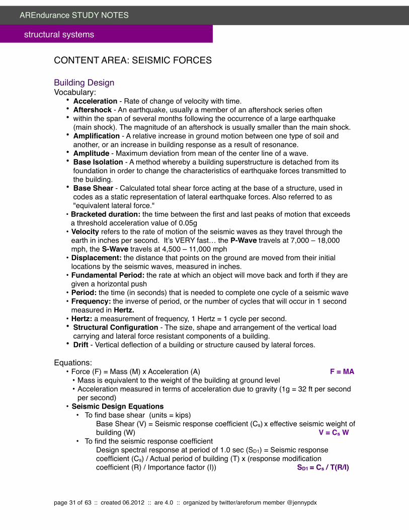
CONTENT AREA: SEISMIC FORCES
Building DesignVocabulary:
• Acceleration - Rate of change of velocity with time.• Aftershock - An earthquake, usually a member of an aftershock series often• within the span of several months following the occurrence of a large earthquake
(main shock). The magnitude of an aftershock is usually smaller than the main shock.• Amplification - A relative increase in ground motion between one type of soil and
another, or an increase in building response as a result of resonance.• Amplitude - Maximum deviation from mean of the center line of a wave.• Base Isolation - A method whereby a building superstructure is detached from its
foundation in order to change the characteristics of earthquake forces transmitted to the building.
• Base Shear - Calculated total shear force acting at the base of a structure, used in codes as a static representation of lateral earthquake forces. Also referred to as "equivalent lateral force."
• Bracketed duration: the time between the first and last peaks of motion that exceeds a threshold acceleration value of 0.05g
• Velocity refers to the rate of motion of the seismic waves as they travel through the earth in inches per second. It’s VERY fast… the P-Wave travels at 7,000 – 18,000 mph, the S-Wave travels at 4,500 – 11,000 mph
• Displacement: the distance that points on the ground are moved from their initial locations by the seismic waves, measured in inches.
• Fundamental Period: the rate at which an object will move back and forth if they are given a horizontal push
• Period: the time (in seconds) that is needed to complete one cycle of a seismic wave• Frequency: the inverse of period, or the number of cycles that will occur in 1 second
measured in Hertz.• Hertz: a measurement of frequency, 1 Hertz = 1 cycle per second.• Structural Configuration - The size, shape and arrangement of the vertical load
carrying and lateral force resistant components of a building.• Drift - Vertical deflection of a building or structure caused by lateral forces.
Equations:• Force (F) = Mass (M) x Acceleration (A)" " " F = MA
• Mass is equivalent to the weight of the building at ground level• Acceleration measured in terms of acceleration due to gravity (1g = 32 ft per second
per second)• Seismic Design Equations
• To find base shear (units = kips)" " " Base Shear (V) = Seismic response coefficient (Cs) x effective seismic weight of " " " building (W) " V = Cs W
• To find the seismic response coefficient " " " Design spectral response at period of 1.0 sec (SD1) = Seismic response " " " coefficient (Cs) / Actual period of building (T) x (response modification " " " coefficient (R) / Importance factor (I)) " SD1 = Cs / T(R/I)
page 31 of 63 :: created 06.2012 :: are 4.0 :: organized by twitter/areforum member @jennypdx
AREndurance STUDY NOTES
structural systems

Facts/Rules:• The human body can feel accelerations as small as 0.001g, (free fall is 1g)• Poorly constructed buildings begin to suffer damage at 0.1g• Moderate earthquakes acceleration is approximately 0.2g • Seismic Design Category, per IBC:
A = building in regions with little probability of earthquakeB = ordinary occupancy that could experience shakingC = structures of ordinary occupancy that experience strong shaking or important Structures that experience medium shakingE = Ordinary building close to a fault lineF = Important building close to a fault line
Concepts/Goals:• FEMA 454: Designing For Earthquakes Chapter 4/Earthquake Effects on
Buildings• Seismic body and surface waves create inertial forces within a building• Inertial forces are created within an object when an outside force tries to make it move
it’s at rest or change its rate/direction of motion if its moving• Light buildings (e.g. wood framed houses) tend to perform better in earthquakes than
large heavy ones because the smaller mass means less force. (F = MA)• Acceleration is a key factor in determining the forces on a building • A more significant measure is that of acceleration combined with duration which takes
into account forces over time.• Typically a number of cycles of moderate acceleration over time can be more difficult to
withstand than a single larger peak. • Continued shaking weakens a building structure and reduces its resistance to
earthquake damage • The velocity of motion on the ground caused by seismic waves is quite slow
(remember, huge chunks of rock and earth are getting moved around) so typically building motion is slow and the distances are small, even thought thousands of tons of steel and concrete are jolted in all directions several times per second
• Earthquake shaking is initiated by a fault slippage in the underlying rock• As the shaking moves to the surface, it might be amplified, but that depends on the
intensity of the shaking, the nature of the rock, and (most importantly) the type/depth of surface soil
• Soft soil (few ft – 100 ft deep) have an amplification factor of 1.5 - 6 over rock shaking• Earthquake damage tends to be more severe in areas of soft ground• Seismic codes have very specific requirements that relate to the characteristics of the
site, including designing for higher force levels and specific foundations on poor soil • Determining earthquake waves’ period, or frequency, (eg: waves that are quick and
abrupt or slow and rolling) is important for determining building seismic forces. • All objects have a natural or fundamental period • Natural periods vary depending on the height of the object. (Building period = number
of stories / 10 )Filing Cabinet" =" 0.05 sec nat. period ="" 1/0.05 frequency =" 20 Hertz1 Story Bldg" =" 0.1 sec nat. period = " " 1/0.1 frequency =" 10 Hertz4 Story Bldg" =" 0.5 sec nat. period = " " 1/0.5 frequency =" 2 Hertz
page 32 of 63 :: created 06.2012 :: are 4.0 :: organized by twitter/areforum member @jennypdx
AREndurance STUDY NOTES
structural systems
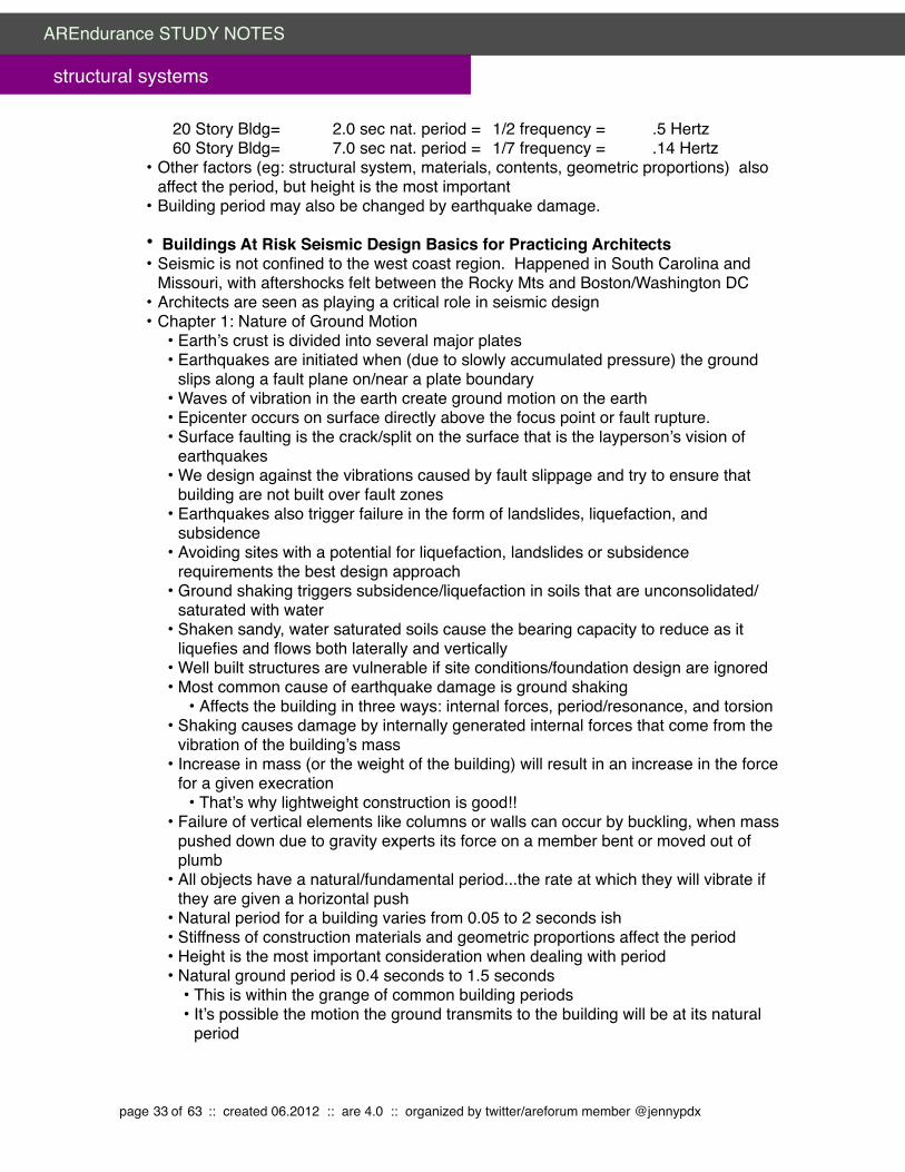
20 Story Bldg=" 2.0 sec nat. period = " 1/2 frequency =" .5 Hertz60 Story Bldg=" 7.0 sec nat. period = " 1/7 frequency = " .14 Hertz
• Other factors (eg: structural system, materials, contents, geometric proportions) also affect the period, but height is the most important
• Building period may also be changed by earthquake damage.
• Buildings At Risk Seismic Design Basics for Practicing Architects • Seismic is not confined to the west coast region. Happened in South Carolina and
Missouri, with aftershocks felt between the Rocky Mts and Boston/Washington DC• Architects are seen as playing a critical role in seismic design • Chapter 1: Nature of Ground Motion
• Earth’s crust is divided into several major plates• Earthquakes are initiated when (due to slowly accumulated pressure) the ground
slips along a fault plane on/near a plate boundary• Waves of vibration in the earth create ground motion on the earth• Epicenter occurs on surface directly above the focus point or fault rupture.• Surface faulting is the crack/split on the surface that is the layperson’s vision of
earthquakes• We design against the vibrations caused by fault slippage and try to ensure that
building are not built over fault zones• Earthquakes also trigger failure in the form of landslides, liquefaction, and
subsidence• Avoiding sites with a potential for liquefaction, landslides or subsidence
requirements the best design approach• Ground shaking triggers subsidence/liquefaction in soils that are unconsolidated/
saturated with water• Shaken sandy, water saturated soils cause the bearing capacity to reduce as it
liquefies and flows both laterally and vertically• Well built structures are vulnerable if site conditions/foundation design are ignored• Most common cause of earthquake damage is ground shaking
• Affects the building in three ways: internal forces, period/resonance, and torsion • Shaking causes damage by internally generated internal forces that come from the
vibration of the building’s mass• Increase in mass (or the weight of the building) will result in an increase in the force
for a given execration• That’s why lightweight construction is good!!
• Failure of vertical elements like columns or walls can occur by buckling, when mass pushed down due to gravity experts its force on a member bent or moved out of plumb
• All objects have a natural/fundamental period...the rate at which they will vibrate if they are given a horizontal push
• Natural period for a building varies from 0.05 to 2 seconds ish• Stiffness of construction materials and geometric proportions affect the period• Height is the most important consideration when dealing with period• Natural ground period is 0.4 seconds to 1.5 seconds
• This is within the grange of common building periods• It’s possible the motion the ground transmits to the building will be at its natural
period
page 33 of 63 :: created 06.2012 :: are 4.0 :: organized by twitter/areforum member @jennypdx
AREndurance STUDY NOTES
structural systems

• Amplification in building vibration is undesirable… so try to ensure that the building period won’t coincide with the ground
• A shot stiff building with short period isn’t appropriate on a soft site with a long period
• Earthquake shaking tends to be greater on soft ground than on hard ground• Earthquakes are more sever in areas of soft ground• Response spectrum: shows the accelerations that may be expected at varying
periods• Base isolation is based on shifting the building period towards the long period of
the spectrum where the response is reduced • Locations closer to the fault from where the energy is release will experience
higher frequency/shorter period ground motion • The farther the building is from the earthquake touch may be subjected to
considerable long-period motion • The center of mass, or center of gravity of an object is the point at which it could
be exactly balance without any rotation resulting• Uniformly distributed mass results in the coincidence of a plan’s geometric center
with the center of mass• If the mass within a floor is uniformly distributed, then the resultant force of the
horizontal acceleration of all its particles of mass is exerted through the floor’s center
• If the resultant of the resistance (walls or frames) pushes back through this point, balance remains
• Torsion is a twisting action on a building...very undesirable • Three basic characteristics of buildings help resist and dissipate the effects of
seismically induced motion: damping, ductility, and straight/stiffness• Damping affects the dynamic behavior of the building and modifies its
response to ground motion. • When damped, buildings are inefficient in their vibration and when set in
motion, return to their starting position quickly. • Ductility is the property of certain materials, typically steel, to fail only after
considerable inelastic (permanent) deformation occurs• Good ductility requires special detailing of joints• Analysis of forces is not precise and deliberately errs on the conservative
side• Strength and stiffness are two of the most important characteristic of any
structure• Deflection is a measure of stiffness…• In the sizing of floor joists, deflection rather than strength governs because
no one wants a bouncy floor...even though it’s safe• Resisting a given load without exceeding a safe stress in the material is a
strength problem• In the design of a floor system, the joists might tolerate a certain deflection
but the ceiling finish cannot.• Relative rigidities of members are a concern of seismic analyst• As soon as a rigid horizontal element or diaphragm is tied to vertical resisting
elements, it will force those elements to deflect the same amount
page 34 of 63 :: created 06.2012 :: are 4.0 :: organized by twitter/areforum member @jennypdx
AREndurance STUDY NOTES
structural systems

• Chapter 2: Site Issues• Seismic design isn’t limited to the actually project site, but the to a broad
environmental analysis of regional and community vulnerability• Factors that impact site vulnerability include proximate to active earthly faults,
susceptibility of the site to ground shaking, the potential for ground failure (subsidence, spreading, liquefaction landslides) adjacent structures and land uses
• If a structure is built over an active fault trace is should be designed to accommodate displacement or fault offset
• In many areas development is limited/prohibited within defined zones adjacent to active faults
• Geology of a region plays a significant role in determining the potential for shaking and ground failure damage
• Understanding the regional and local geology can tell the designer a great deal about the relative risk of an individual site
• Damage to lifeline systems (water, sewer, power, transport, communication) can isolate a structure and cease its ability to operate, even if the structure is ok
• Only occasionally is the architect responsible for site selection… most of the time the client provides it, unaware of the risks and vulnerability
• Site analysis should include an assessment of the environment beyond the property line and include adjacent structures and site conditions that could “spill over” onto the site
Building Systems and their IntegrationVocabulary:
• Bearing Wall: A wall providing support for vertical loads; it may be interior or exterior. • Nonbearing Wall (Partition): A wall that does not provide support for vertical loads
other than its own weight as permitted by the building code. It may be interior or exterior.
• Shear Wall: A wall, bearing or nonbearing, designed to resist seismic forces acting in the plane of the wall.
• Bearing Wall System: A structural system with bearing walls providing support for all or major portions of the vertical loads. Seismic resistance may be provided by shear walls or braced frames.
• Braced Frame: One which is dependent upon diagonal braces for stability and capacity to resist lateral forces. In concentric braced frames, diagonal braces are arranged concentric to column/beam joints; in eccentric braced frames, they are eccentric.
• Moment Frame: A space frame in which members and joints are capable of resisting lateral forces by bending as well as along the axis of the members. Varying levels of resistance are provided by Ordinary, Intermediate and Special Moment Frames as defined in the NEHRP Provisions with Special Frames providing the most resistance.
• Space Frame: A structural system composed of interconnected members, other than bearing walls, that is capable of supporting vertical loads and that may also provide resistance to seismic forces.
Concepts/Goals:• Moment resisting frames provide the most architectural design freedom• Chapter 3: Building Configuration
page 35 of 63 :: created 06.2012 :: are 4.0 :: organized by twitter/areforum member @jennypdx
AREndurance STUDY NOTES
structural systems

• Building configuration is used in seismic design to define the architectural form• Configuration: building size and shape, the size and location of structural
elements, and the nature, size and location of non structural elements that may affect structural performance (e.g.: heavy non structural walls, heavy equipment)
• Building configuration primarily determines the way forces are distributed throughout the structure and the relative magnitude of those forces
• Seismic codes distinguish between regular and irregular configurations and it is the latter that may have a detrimental influence on the effectiveness and cost of seismic engineering and the seismic performance itself.
• Regular/uniform configurations that are seismically optimal are:Shear wallsMoment resistant framesBraced frames
• Because they have:Low height to base ratioEqual floor heightsSymmetrical planUniform section and elevationsMaximum torsional resistanceBalanced resistanceShort spans/redundancy
• Direct load paths• Buildings with circular plans form are even better because of their total
symmetry, but are structurally more complex, and not very useful in urban design
• Very large forces may build up in diaphragms that must be resisted by shear walls of frames. While ideally seismically, it can present deficit internal planning
• Irregular configuration occur when the building deviates from a simple regular symmetrical form in plan and sections. Causes problem in torsion and stress concentration
• Torsional problems are most typically associated with plan irregularity or geometers
• Stress concentrations occur when an undue proportion of the overall seismic force is concentrated at one or few location in the building...like at a set of beams or columns
• Many buildings fail because of the lack of balanced resistance which results in stress being placed on the member, which consequently over stresses of fails the system
• Irregularity in shape often occurs for sound planning or urban design...not necessarily because of whim.
• Essentially, the seismic design problem is too complex to be dealt with by code rules...it must be left to engineering.
• Soft First Stories• Ground level story has adequate strength but is less stiff than those above• Structures with weak stories are limited to two stories or 30’ height• A building’s deflection under horizontal forces being distributed equally
among the upper floors it’s accommodated almost entirely in the first floor
page 36 of 63 :: created 06.2012 :: are 4.0 :: organized by twitter/areforum member @jennypdx
AREndurance STUDY NOTES
structural systems

• Avoid the soft story through design...if not possible, then add columns or bracing
• Discontinuous Shear Walls• When shear walls form the main lateral resisting elements of the building,
they may be required to resist very high lateral forces. • If these walls do not line up in plan from one floor to the next, the forces
cannot flow directly down through the walls from roof to foundation, and the consequent indirect load path can result in serious overstressing at the points of discontinuity
• A discontinuity in vertical stiffness and strength leads to a concentration of stresses and ultimately to damage and collapse, and the story which must hold up the remaining stories in a building should be the last, rather than the first, component to be sacrificed
• Variations in Perimeter Strength and Stiffness• A building's seismic behavior is strongly influenced by the nature of the
perimeter design. • If there is wide variation in strength and stiffness around the perimeter, the
center of mass will not coincide with the center of resistance, and torsional forces will tend to cause the building to rotate around the center of resistance
• Design a frame structure of approximately equal strength and stiffness for the entire perimeter
• Increase the stiffness of open facades by adding shear walls at/near the open face
• Use a very strong moment resistant or braced frame at the open front• Design a stiff diaphragm to transfer forces abc into a resisting structural
systems • Reentrant corner is the common characteristic of building forms that assume
the shape of an L, T, H, etc• These shapes tend to produce variations of rigidity and hence differential
motions between different portions of the building, resulting in a local stress concentration at the reentrant corner
• Torsion is caused because the center of mass and the center of rigidity cannot geometrically coincide
• The stress concentration at the "notch" and the torsional effects are interrelated. The magnitude of the forces and the seriousness of the problem will depend on:
• the mass of the building,• the structural system,• the length of the wings and their aspect ratios, and• the height of the wings and their height/depth ratios
• Configuration problems originate in the schematic design of a building • Chapter 4: Seismically Resistance Structural Systems:
• Structural engineers typically equate design capacity with loads imposed on it (live loads, wind loads, etc.)
• Appropriate safety factors ensure that materials never exceed the elastic range of behavior
• Diaphragms
page 37 of 63 :: created 06.2012 :: are 4.0 :: organized by twitter/areforum member @jennypdx
AREndurance STUDY NOTES
structural systems

• Horizontal resistance elements (floors/roofs) transfer lateral force between vertical resistance elements
• Size and location of penetration is critical to the effectiveness of the diaphragm• Shear Walls
• Vertical cantilever walls designed to receive lateral forces from diaphragms and transmit them to the ground
• Size and location is very important • Braced Frames:
• Act like shear walls but may be of lower resistance and stiffness depending on design
• Vibrating forces may cause bracing to elongate or compress...and then it loses its effectiveness and permits large deformations or collapse
• Can be designed in a variety of systems• Moment Resistant Frames
• Lateral forces are resisted by rotations of the beam/column joints• Induces shear and bending forces in the frame members • Joints become highly stressed and design and construction becomes critical • Most are steel structures with stiff welded joints in which the natural ductility of
the material is of advantage• Use of moment frames obviates the need for shear walls or braced frames and
the tend to be much more flexible than shear walls type structures• Eccentric bracing combines the ductility of the moment frame with the rigidity or drift
control of the conventional brace• Dual moment frame/shear wall combines ductility with rigidity• Progressive Resistance Systems combine 2 or 3 systems that progress in load-
carrying capacity from rigidity to ductility at predetermined load levels• Base isolation, in which the superstructure of the building is partially isolated from
ground by motion and use of bearings • Selecting a structural system in a highly seismic area is a complex task• The factors that must be considered when selecting a system are:
• Anticipated level of earthquake ground motion• Site geology and its impact on the structure• Building occupancy and impact on building form and structural system• Building configuration which may be arbitrary or dictated by site, zoning, program• Structural system relative to the configuration• Structural details • Non structural components (Cladding, ceilings, partitions, etc.) in relation to the
primary structure• Construction quality and its impact on structural continuity
• Seismic requirements in code are intended only to assure life safety• Only the primary structure must be protected to prevent collapse
Implications of Design DecisionsVocabulary:
• Triggers: events or actions that require seismic retrofit
Concepts/Goals:• Chapter 6: Nonstructural Damage:
page 38 of 63 :: created 06.2012 :: are 4.0 :: organized by twitter/areforum member @jennypdx
AREndurance STUDY NOTES
structural systems

• Nonstructural components are those that aren’t part of the structural system• Nonstructural damage is the cause of much economic loss and its repair may leave
building unusable for weeks• Four types of safety hazards presented by nonstructural components are:
• Direct hazard - the possibility of casualties because of broken glass, light fixtures, appendages, etc.,
• Loss of critical function - casualties caused by loss of power to hospital life support systems in bed panels, or functional loss to fire, police or emergency service facilities,
• Release of hazardous materials - casualties caused by release of toxic chemicals, drugs, or radioactive materials and,
• Fire caused by nonstructural damage - damage to gas lines, electrical disruption, etc.
• Economic loss refers to the direct cost of repairing nonstructural damage• Nonstructural elements may modify the designed structural response in ways
detrimental to the safety of the building • Nonstructural damage is due to acceleration or replacement
• Chapter 8: Seismic Design Process• Overall responsibility for seismic design is shared between architect and structural
engineer• Damage free seismic design can’t be guaranteed• Higher level of seismic design can be done..but at a higher construction cost
• Chapter 9: The Planning Process:• City/regional planning policies play a significant role providing for the growth,
development, governance, and maintenance of communities. • The key decision maker for providing seismic safety to communities is the local
government• Comprehensive Planning includes nearly every topic related to public safety, social
equality and environmental quality. • Primary concern to public safety is damage or collapse of older structure built during
a period when seismic code didn’t exist or were inadequate to resist earthquake forces
Construction Details and Constructability Vocabulary:
• Nonstructural: systems and components that are part of a building that don’t like in the primary load bearing path of the building
Facts/Rules:• Non Structural Components have historically received little attention from designers
regarding seismic performance. The following are typically included in that set: • Interior nonstructural walls and partitions• Cantilever elements
• Parapets • Chimneys
• Exterior nonstructural wall elements and connections • Light wall elements (metal insulated panels) • Heavy wall elements (precast concrete)
page 39 of 63 :: created 06.2012 :: are 4.0 :: organized by twitter/areforum member @jennypdx
AREndurance STUDY NOTES
structural systems

• Body of panel connections • Fasteners of the connecting systems
• Veneer • Limited deformability elements • Low deformability elements
• Penthouse (separate from main building structure)• Ceilings
• Suspended • Attached to rigid sub-frame
• Cabinets • Storage cabinets and laboratory equipment
• Access floors• Appendages and ornamentation• Signs and billboards• Other rigid components• Other flexible components• General mechanical
• Boilers and furnaces • Pressure vessels freestanding and on skirts • Stacks • Large cantilevered chimneys
• Manufacturing and process machinery • General • Conveyors (nonpersonnel)
• Piping system • High deformability elements and attachments • Limited deformability elements and attachments • Low deformability elements and attachments
• HVAC system equipment • Vibration isolated • Nonvibration isolated • Mounted in-line with ductwork
• Elevator components• Escalator components• Trussed towers (freestanding or guyed)• General electrical
• Distributed systems (bus ducts, conduit, cable trays) • Equipment
• Lighting fixtures • Surface mounted to structure • Suspended from structure • Supported by suspended ceiling grid, surface mounted, or hung from suspended
ceiling• Construction details for appropriate seismic design of nonstructural elements
• Suspended ceilings are braced by wires or rigid members no more than 144 square feet
• Lighting fixtures must be supported independently, so if the lay-in ceiling falls, the light won’t
page 40 of 63 :: created 06.2012 :: are 4.0 :: organized by twitter/areforum member @jennypdx
AREndurance STUDY NOTES
structural systems

• Heavy partitions like CMU should be separated from surrounding structure to avoid local stiffing and to avoid transmitting racking forces to the wall
• Metal studs that terminate at a lay-in ceiling should e braced independently (kickers) to the building structure
• Heavy parapets should be braced back to the roof structure• Sheet metal ductwork should be anchored and hung with threaded rods• Vibration isolated equipment is fitted with “snubbers” that limit lateral motion to
prevent the equipment toppling off the isolators and suffering damage• Emergency power equipment needs a positive restraint• Tall shelving need longitudinal bracing and attachment to the floor• Gas water heaters need restraint to prevent it from toppling over and breaking the
gas connection
Concepts/Goals:• Chapter 7: Seismic Rehabilitation of Existing Buildings:
• Seismic criteria for new buildings is generally inappropriate for use with old buildings• It’s either too expensive or unworkable• Primary goal of seismic rehabilitation is to provide for life safety by minimizing the
collapse exposure• Unreinforced masonry bearing wall building with poorly tied floor and roof framing
lack integrity and stability and usually fail by wall collapse in out of plane motion• Non ductile concrete frames are subject to sudden shear failure of the weak
unconfined columns• Steel diagonally braced structures can suffer non ductile fractures of the braces or
connections• Adding strength alone is not enough to ensure seismic stability• Base isolation is becoming common for rehabilitation of historic structures
Processes:• Dynamic structural analysis: Tall buildings with complex shapes or unusual conditions
a computer• model is used to study what forces are developed
-Most cases building codes allow a static analysis of the loads• Static analysis method: total horizontal shear at base is calculated according to
standard formula-Total lateral force is distributed to various floors
Construction MaterialsVocabulary:
• Brittle Failure: Failure in a material which generally has a very limited plastic range; material subject to sudden failure without warning.
• Elastic: The ability of a material to return to its original form and condition after a displacing force is removed.
• Ductility - Property of some materials, such as steel, to distort when subjected to forces while still retaining considerable strength.
• Energy Dissipation - Reduction in intensity of earthquake shock waves with time and distance, or by transmission through discontinuous materials with different absorption capabilities.
page 41 of 63 :: created 06.2012 :: are 4.0 :: organized by twitter/areforum member @jennypdx
AREndurance STUDY NOTES
structural systems

• Inelastic - The inability of a material to return to its original form and condition after a displacing force is removed; permanent distortion.
• Intensity - A subjective measure of the force of an earthquake at a particular place as measured by its effects on persons, structures and earth materials. Intensity is a measure of energy. The principal scale used in the United States today is the Modified Mercalli, 1956 version.
• Liquefaction - Transformation of a granular material (soil) from a solid state into a liquified state as a consequence of increased pore-water pressure induced by vibration.
Concepts/Goals:• Required lateral strength of a seismic system is traded off with ductility (The ability to
deform inelastically) remember...higher strength requires lower ductility• At higher levels of shaking, the exterior walls of unreinforced masonry bearing wall
buildings have relatively consistently fallen away from their buildings
Government and Regulatory Requirements and Permit ProcessVocabulary:
• Design earthquake ground motion: the earth quake ground motion that buildings and structure are specifically proportioned to resist in the IBC
• Maximum considered earthquake ground motion: the most severe earthquake effects considered by IBC
• Mechanical systems: in terms of seismic design, this includes HVAC and plumbing• Orthogonal: to be in two horizontal directions at 90degrees to each other• Seismic Design Category: classification assigned to a structure based on its
occupancy category and the severity of the design earthquake ground motion at the site
• Seismic Force Resisting System: the part of the structural system that has been considered in the design to provide the required resistance to the prescribed seismic forces
• Site Class: classification assigned to a site based on the types of soils present and their engineering properties (A: hard rock, B: rock, C: dense soil, D: stiff soil, E: soft soil, E: varies, F: varies w/multiple characteristics)
Facts/Rules:• I “Every structure and portion thereof, including nonstructural components that are
permanently attached to structures and their supports and attachments, shall be designed and constructed to resist the effects of earthquake motions in accordance with ASCE 7, excluding Chapter 14 and Appendix 11A.”
•Exceptions (earthquake analysis not required): •Detached one- and two-family dwellings in Seismic Design Categories A, B or C. •Seismic-force-resisting wood-framed structures complying with IBC Section 2308. •Agricultural buildings with no human occupancy.
• IBC Earthquake Design Data (1603.1.5) must be addressed with construction documents
• Seismic importance factor I and occupancy category• Mapped spectral response accelerations Ss and SI• Site class
page 42 of 63 :: created 06.2012 :: are 4.0 :: organized by twitter/areforum member @jennypdx
AREndurance STUDY NOTES
structural systems

• Spectral response coefficients SSD and SDI• Seismic design category• Basic seismic force resisting systems• Design base shear• Seismic response coefficient(s) CS• Response modification factor(s) R• Analysis procedure used
Concepts/Goals:• Chapter 5: The basics of Seismic Code
• Most codes have the stated goal of maintaining life safety• Damage control is included in codes for hospitals/critical buildings• The primary purpose of seismic code is to provide a simple uniform method to
determine the seismic forces for any location with enough accuracy to ensure a safe and economical design
• Code needs to provide for approximate uniformity of results so that no building owner, type, or material supplier is unfairly discriminated against.
• Horizontal force on a building can be represented as a horizontal shear force trying to push the base of the building across the ground where it’s attached to its foundation
• FEMA 454: Designing For Earthquakes Chapter 1/Introduction• Earthquakes must be accepted as a natural environmental process• Characteristics of the site, the earthquake and the structure influence seismic
performance• Economic losses can be very high in industrialized countries for earthquakes that kill
relatively few people due to the fragility of buildings’ interior, systems, and enclosures• Good seismic engineering can provide structures that can survive to a useful degree
of predictability • Key players in ensuring safe seismic design are the seismologist and structural
engineer• Architect initiates the building design and determines issues related to configuration
(eg: size, shape, form/location of structural elements) that influence the seismic performance
• Inspection and analysis of earthquake-damaged buildings play important roles in understanding the effectiveness of seismic design
Processes:• Simplified Seismic Design Process: (PROBABLY OVERKILL FOR THE EXAM)
• Determine Ground Motion Spectral Response Acceleration • SS = Ground acceleration at short (0.2 second) period
" = see Figure 1613.5(1) • S1 = Ground acceleration at longer(1 second) period
" " = see Figure 1613.5(2) • Determine “Site Class”:
• Site class is based on seismic shear wave velocity, vs, traveling through the top 100 feet of ground.
• Site class is determined from Table 1613.5.2 on p. 303
page 43 of 63 :: created 06.2012 :: are 4.0 :: organized by twitter/areforum member @jennypdx
AREndurance STUDY NOTES
structural systems

• • Determine “Maximum Considered Earthquake” Spectral Response:
• SMS = FaSS • where: Fa = Site coefficient based upon Site Class
= From Table 1613.5.3(1) p. 304 • SM1 = FvS1
" where: Fv = Site coefficient based upon Site Class = From Table 1613.5.3(2) p. 304
• Determine Design Spectral Response Acceleration: • SDS = 2/ 3 (SMS) per IBC Equation 16-39 • SD1 = 2/3 (SM1) per IBC Equation 16-40
• Determine “Response Modification Coefficient R• From ASCE 7 Table 12.2.1
• Determine the Effective Seismic Weight of Structure “W”• W = Effective seismic weight of structure
• = Total dead load of structure + • In areas used for storage, a minimum of 25% of the reduced floor live
load (floor live load in public garages and open parking structures need not be included)
• Where an allowance for partition load is included in the floor load design, the actual partition weight or a minimum weight of 10 PSF of floor area, whichever is greater.
• Total operating weight of permanent equipment • 20% of uniform flat roof snow load where the flat roof snow load “Pf”
exceeds 30PSF.• Determine Seismic Importance Factor
• Per Occupancy Category IBC 1604.5• I or II " " " =" " " 1.0• III"" " " =" " " 1.25• IV"" " " =" " " 1.5
• Determine Seismic Base Shear “V” • V = CsW
• Determine Vertical Distribution of Seismic Shears• Fx = CvxV where: Cvx = wxhx
∑wihI
• where: h = height above base (feet) • w = portion of weight at that level
page 44 of 63 :: created 06.2012 :: are 4.0 :: organized by twitter/areforum member @jennypdx
AREndurance STUDY NOTES
structural systems

CONTENT AREA: WIND FORCES
Building DesignVocabulary:
• Building drift: the distance a building moves in wind• Straight Line Wind: most common wind type, blows in a straight line• Down Slope Wind: wind that flows down the slope of a mountain• Special Wind Regions: mountainous areas in the continental US• Thunderstorm: rapidly forming storm that produces high wind speed• Downburst: An area of significantly rain-cooled air that, after reaching ground level,
spreads out in all directions producing strong winds. Associated with thunderstorms • Northeaster: cold, violent storm that occurs along NE coast and last for days• Hurricane: spiraling wind systems that converge with increasing speed towards the
storm’s center (eye)• Tornado: rotating column of air that extends from base of thunderstorm to the ground• Exposure: classification for the characteristics of the ground roughness and surface
irregularities in the vicinity of a building • Basic Wind Speed: the wind speed with a 50 year average recurrence interval
measured at 33’-0” above grade in Exposure C (flat, open terrain) It is a peak gust speed
• Aerodynamic Pressure: the interaction between the wind and the building
Facts/Rules:• Hurricane forward movement (translational speed) varies between 5 – 25 mph
• Saffir-Simpson Hurricane Scale rates intensity of hurricanes • Category I (weakest) – Category V (strongest)
• Hurricanes have the greatest potential for devastating a large geographical area
• Tornado path widths are less than 1,000 ft (but have been reported 1-mile across)•Fujita scale categorizes severity based on observed damage
• F0 (light damage) – F5 (incredible damage)• F0/F1 are most common, but F2/F3 frequently occur
• When wind interacts with a building, both positive and negative (suction) pressure occurs simultaneously. If wind is approaching front wall, then:
• Front Wall " " " =" " " Positive pressure • Rear Wall" " " =" " " Negative pressure• Side Walls" " " =" " " Negative pressure• Roof" " " " =" " " Uplift
• Otherwise said: positive pressure occurs on the windward side of a building and Negative pressure (suction) occurs on the on leeward side & roof
• Pressure is greater at corners, overhangs & parapets• Exposure Categories:
• Exposure B: rough terrain, urban, suburban, and wooded areas• Exposure C: flat open terrain with scattered obstructions and areas adjacent to
oceans in hurricane prone regions • Exposure D: smoothest terrain, areas adjacent to large water surfaces outside
hurricane-prone regions, mud flats, salt flats, and unbroken ice
page 45 of 63 :: created 06.2012 :: are 4.0 :: organized by twitter/areforum member @jennypdx
AREndurance STUDY NOTES
structural systems

• The smoother the terrain, the greater the wind load. (eg: office buildings in exposure D would receive higher wind loads than those in Exposure B)
• Most of country has a basic wind speed (peak gust) of 90 mph, but it’s much higher in places like Alaska or in hurricane prone regions
• Abrupt changes in topography (isolated hills, ridges, etc) cause wind to speed up. • Wind speed increases with height above ground. The taller the building the greater the
wind speed and wind loads• Wind striking a building causes internal pressure, either positive or negative, because
of the porosity of the building envelope (openings around doors/window frames, and other walls that aren’t airtight)
• Damage typically begins with peak gusts of 70 – 80 mph• Tall building can drift several feet• The max drift allowed = 1/500 x height of building
Concepts/Goals:• Different wind types and storms occur in different areas of the country• Thunderstorms produce high winds and create heavy rain…sometime leads to hail and
tornadoes• Move through an area rapidly, causing high wind at a given location for a few moments
• Can stall and become stationary • Pressures, directions and timing of wind is constantly changing• For purpose of calculation however wind is considered a static force based on:
• Velocity: pressure on building varies as the square of the velocity• Height of wind above ground• Surroundings: other buildings, trees and topography• Size, shape and surface texture
Processes:• When designing for wind, consider the following:
• Regular winds: low to moderate wind that occurs daily. Damage is not expected to occur at this speed
• Stronger winds: winds with a basic wind speed of 70-80mph peak gusts that occur a few times a year.
• Design Level Winds: can cause extensive damage to building and structure. • Tornadoes: only a few areas frequently experience tornadoes, but areas that do
should consider design. Well designed/built/maintained buildings should experience little damage, except for window breaks.
• Risk Reduction Strategy:• Siting:
• Don’t locate a building in Exposure D if possible• Avoid locating on upper half a hill• Trees with 6”+ diameter, light/flag/power poles shouldn’t be placed near
building• Provide at least two means of site egress for office/public buildings
• Building Design:• Good, design (including details and specifications), materials,
application, maintenance, and repair
page 46 of 63 :: created 06.2012 :: are 4.0 :: organized by twitter/areforum member @jennypdx
AREndurance STUDY NOTES
structural systems

• Calculate Loads on the system (structure, building envelope, rooftop equipment)
• Determine load resistance, reasonable safety factor, or reasonable load factor.
• Design, detail, and specify structural system, building envelop, exterior MEP to meet the design loads and ID load path clearly on construction documents
• Ensure durability of materials. Weather can damage or destroy building components designed to protect the structure from failure
• Minimize water damage and subsequent development of mold. • Peer Review
• Either in house or from experts, especially when building is:• Located in an area with a peak gust greater than 90 mph• Will be used for emergency response after a storm• Will be used for a hurricane shelter• Will incorporate a tornado shelter
• Construction contract Administration• Review submittals• Conduct field observations
• Post Occupancy Inspections, Maintenance, Repair, and Replacement • It’s important for the building owner to understand that over time, a
building’s ability to resist wind loads will degrade due to exposure to elements. It must be periodically repaired
• The goal is to repair or replace items before the fail in a storm…it’s less messy and less expensive!
Building Systems and their IntegrationFacts/Rules:
• Damage to buildings from wind ranges from minimal to severe • Roof covering damages: rooftop mechanical/electrical moved, flashing lifted,
built-up membrane peeled, etc.• Exterior wall coverings and soffit damages: exterior wall fail or collapse• Structural damage: roof blows off, exterior bearing walls collapse, entire
building collapses
Concepts/Goals:• High wind performance of building envelopes has historically been poor due to
inadequate design attention • Well designed/constructed/maintained buildings may be damaged by wind forces
much strong than it was designed for…though it’s rare (except for tornados)• Most damage occurs because building elements have limited resistance due to poor
design, material deteriorate, or roof system abuse• In tornado prone regions, consideration should be given to designing a portion of the
building for occupant protection• Damage to buildings and structure cause certain ramifications:
• Property damage: repair/replacement of damaged components, repair/replacement of damaged internal components, mold remediation, furniture/equipment damage from water entering building
page 47 of 63 :: created 06.2012 :: are 4.0 :: organized by twitter/areforum member @jennypdx
AREndurance STUDY NOTES
structural systems

• Debris can blow from building and damage cars and other buildings (HVAC equipment, wall coverings, etc)
• Injury or death: either building occupants or people struck by debris• Interrupted use: can’t use the building while it’s being repaired
Processes:• Evaluating buildings for risk from high winds (other than tornadoes)
• Determine basic wind speed. • As it increases beyond 90mph, the risk of damage increases• Design, construction and maintenance enhancements are
recommended for higher wind speeds• If building is outside of hurricane prone region, determine if building will be used
for emergency response after a storm• If yes, then design/build/maintain like building is in hurricane prone
region • If building is in hurricane prone region, determine if it will be used for
emergency response after a storm
Implications of Design DecisionsFacts/Rules:· Buildings used for emergency response after a storm typically require design
decisions that add little cost to the total cost of construction
Concepts/Goals:· For many parts of the USA, high wind is the most severe load that affects a building
·Annually, wind damage to buildings/structures exceeds all other natural disaster combined·Hurricane Katrina = $96 – 125 billion in damages (including flood damage)
Construction Details and Constructability Facts/Rules:
• Good design details can help save a building in the event of a wind storm• High wind forces travel through the load path of a structure• Good connections that tie the floor, walls and roof together provide continuity in the
load path and better building performance• Light Wood Frame Construction:
• Nail roof sheathing along ends of the sheathing of intermediate roof framing • Tie gable end walls back to the structure (one of the weakest connection points)• Sheath gable end walls with wood structural panels (plywd or OSB)• Use seismic/hurricane framing anchor to attach roof framing to the exterior side
of the wall to prevent uplift and shear stress failure• Nail upper and lower story sheathing to common wood structural panel to
provide lateral and uplift load continuity• Continuously sheath all walls with wood structural panels including around
openings for windows/doors• Extend structural panel sheathing to lap the sill plate• The connection of the wall sheathing to sill plate is where uplift forces are
transferred into the plate and into the foundation through anchor bolts
page 48 of 63 :: created 06.2012 :: are 4.0 :: organized by twitter/areforum member @jennypdx
AREndurance STUDY NOTES
structural systems

• Space anchor bolts about 32” – 48” o.c.
Concepts/Goals:• Large openings in walls like windows/sliding glass doors/garage doors are vulnerable
to damage in high wind• Consider windows/doors that are rated for high wind and impact damage• Hip roofs have a long history of superior performance in high wind events compared to
gable end styles
Construction MaterialsFacts/Rules:· Structural System·Greatest reliability is offered by cast-in place concrete. •There are no repots of any cast in place concrete buildings experiencing significant
structural problems during even the most severe wind events·Exterior load bearing walls of masonry/precast concrete should be designed to have
sufficient strength to resist internal/external loads·CMU walls should have vertical and horizontal grout to resist wind load·Connections of precast concrete wall panels should have sufficient strength to resist
wind loads·Detail and specify connections for concrete, steel, or wood sheathing roof decks·For steel roof decks, specify screw attachments rather than puddle welds·For wood sheathed roof decks, specify screws, ring-shank nails in the corner
regions of the roof (and at perimeters with peak wind is +90mph)·For precast concrete decks, design deck connections to resist the design of uplift
loads. The dead load of the deck itself is often inadequate to resist uplift ·For precast Tee decks, design the reinforcing to accommodate the uplift loads in
addition to the gravity loads, otherwise it can fail due to its own pre-stress forces when the uplift load exceeds the dead load of the tee·Single-ply or modified bitumen membranes on decking should meet requirements
•Exterior Doors (egress, garage, and rolling) ·Door assembly (door, hardware, frame) will resist positive and negative design wind
pressure·Anodized aluminum of galvanized doors/frames with stainless steel anchors are
good when corrosion is a problem·Door hardware should minimize the possibility of door being pulled upon by wind
suction (eg: doors with top and bottom rods instead of latches)•Weatherstripping·Pre-manufactured components protect building from water infiltration at doors/
windows•Drip: shed water away from opening between the frame and door head, and
between the door bottom and threshold•Door Shoes and Bottoms: minimize the gap between the door and threshold and
can incorporate a drip•Thresholds: must meet ADA requirements at high traffic doors
•Loads and Resistance·Exterior non load bearing walls, wall coverings, and soffits need to be able to resist
positive/negative wind pressure
page 49 of 63 :: created 06.2012 :: are 4.0 :: organized by twitter/areforum member @jennypdx
AREndurance STUDY NOTES
structural systems

·If a soffit is blown away and the wall doesn’t extend to the roof deck, wind driven water can be blown into the attic and lead to damage and collapse·Exterior non load bearing masonry walls must designed to resist the positive and
negative wind load so they don’t collapse·Brick veneer, EIFS, metal wall panels, stucco and aluminum and vinyl siding often
exhibit poor wind performance. ·Veneers (eg: ceramic tile, stucco) over concrete and cement-fiber panels and siding
have also blown off. ·Blow-off of wood siding and panels is rare. ·Another performance failure is deterioration of fasteners over time caused by water
infiltration. Because the fasteners are often unseen, concealed within the wall assembly, this can ultimately lead to wall covering failure under wind loads.
•Roof Systems·IBC requires load resistance of the roof assembly to be evaluated by one of the test
methods listed in IBC's Chapter 15·the highest uplift load occurs at roof corners·The traditional edge flashing/coping attachment method relies on concealed cleats
that can deform under wind load and lead to disengagement of the flashing/coping·use of exposed fasteners to attach the vertical flanges of copings and edge
flashings has been found to be a very effective and reliable attachment method•Windows/Skylights·IBC requires the window, curtain wall, or skylight assembly (i.e., the glazing, frame,
and frame attachment to the wall or roof) to have sufficient strength to resist the positive and negative design wind pressure·In tornado-prone regions, for critically important buildings it may be desirable to
have laminated glazing installed at exterior openings in order to provide windborne debris protection during weak tornadoes.
•Exterior Mounted MEP/Communications Equipment·Exterior-mounted mechanical (e.g., exhaust fans, HVAC units, relief air hoods, boiler
stacks), electrical, and communications equipment (e.g., light fixtures, antennae, satellite dishes) are often damaged during high winds·Damaged equipment can impair the use of the building, the equipment can become
missiles, and water can enter the facility where equipment was displaced·Problems typically relate to inadequate equipment anchorage, inadequate strength
of the equipment itself, and corrosion.·It is common for equipment components such as fan cowlings and access panels to
be blown off during storms. Design of these elements is the responsibility of the equipment manufacturer.
Concepts/Goals:• Most common problem with materials is blow-off of the roof deck
Government and Regulatory Requirements and Permit ProcessVocabulary:•Main Wind Force Resisting System (MWFRS): a structural assembly that provides
for the overall stability of the building and receives wind loads from more than one surface (eg: shear walls, diaphragms, rigid frames, space structures)
page 50 of 63 :: created 06.2012 :: are 4.0 :: organized by twitter/areforum member @jennypdx
AREndurance STUDY NOTES
structural systems

Equations:· Velocity pressure (qz) evaluated at height “z” " " qz = 0.00256KzKdV2Iw
! qz = " velocity pressure at height “z” in lbs. per square foot " Kz = " velocity pressure exposure coefficient evaluated at height “z” and " Exposure B, C or D (from IBC 1609.4) " Kd = " wind directionality factor, ranging from 0.85 (buildings) or 0.95 (chimneys) " V = " basic wind speed in MPH for 3-second gust at 33 ft. above ground in " Category C as shown in IBC Figure 1609 " Iw = " Importance factor for wind design as shown in IBC Table 1604.5
· Design Wind Pressure (p) p = qzGCp – qz(GCpi)p = " design wind pressure for main wind force-resisting system (MWFRS), psf
" qz = " velocity pressure at height “z” (see above) " G = " 0.85 " Cp = " external pressure coefficient (typically given) " GCpi = 0.0 for open buildings " = +0.55 or -0.55 for partially enclosed buildings " = +0.18 or -0.18 for enclosed buildings
Facts/Rules:• IBC Wind Design Data (1603.1.4) must be addressed with construction documents
• Basic wind speed (3 second gust) in MPH• Wind importance factor I, and occupancy category• Wind exposure, if more than one is utilized, the wind exposure and applicable wind
direction shall be indicated• Applicable internal pressure coefficient• Components and cladding. (the design wind pressure in terms of psf to be used for
the design of exterior components and cladding materials not specifically designed by the registered design professional)
• Wind Loads (Section 1609)• Decreases in wind loads will not be made of the effect of shielding by other
structures • In wind born debris regions, glazing in buildings will be impact-resistance or ate
least protected by an impact-resistant covering • Areas vulnerable to hurricanes are:
• The US Atlantic Ocean and Gulf of Mexico coasts where basic wind speed is greater than 90mph
• Hawaii, Puerto Rico, Guam, Virgin Islands, and American Samoa• Basic wind speed in mph for wind loads is based on Figure 1609 in the IBC
• Special wind regions (near monotonous regions, gorges, etc) must meet local jurisdiction requirements
• In non hurricane regions, basic wind speed is estimated from regional climactic data• Wind loading will be determined per Chapter 6 of ASCE 7 or by Section 1609.6
“simplified wind load method”
Concepts/Goals:• IBC, American Society of Civil Engineers (ASCE), Minimum Design Loads for Buildings
and other Structures, do not provide guidance on wind speeds in special wind regions
page 51 of 63 :: created 06.2012 :: are 4.0 :: organized by twitter/areforum member @jennypdx
AREndurance STUDY NOTES
structural systems

• Local building departments typically establish basic speed. If not, then consult with wind engineers or meteorologists
• The cost for complying with the IBC should be considered as the minimum baseline cost
Processes:· Calculating Wind Pressure on the Main Wind Force-Resisting System
•Determine the average roof height above the ground•Height of wall + 1/2(height of roof) = h
•Determine the Exposure Category (either given, or from IBC Section 1609.4)•Determine the velocity pressure qz
•Use: qz = 0.00256KzKdV2Iw•Answer will be in PSF
•Determine the wind pressure on the Windward wall (p)•Use: p = qzGCp – qz(GCpi)•Answer will be in PSF
•Determine the wind pressure on the Leeward wall (p)•Use: p = qzGCp – qz(GCpi)•Answer will be in PSF•A negative answer indicates a negative “suction force”
•Determine the wind pressure on the Windward roof •Determine the roof to length ratio = h / Length of building (L)
•Determine the roof angle (θ) as measure from the horizontal • θ = tan-1(height of roof / half of width of building)
•Determine Cp (given, or ASCE 7 Figure 6-6) for “Wind Normal to Ridge for θ ≥100”:
•Now you can determine the wind pressure (p) •Use: p = qzGCp – qz(GCpi)•Answer will be in PSF
•Determine the wind pressure on the Leeward roof •Determine Cp (given, or ASCE 7 Figure 6-6) for “Wind Normal to Ridge
for θ ≥100”: •Now you can determine the wind pressure (p)
•Use: p = qzGCp – qz(GCpi)•Answer will be in PSF
•Determine the wind pressure on the gable end walls •Determine Cp (given, or ASCE 7 Figure 6-6) for “Side walls”•Now you can determine the wind pressure (p)
•Use: p = qzGCp – qz(GCpi)•Answer will be in PSF
•Draw “Summary Sketches” showing Worst Case Loads
page 52 of 63 :: created 06.2012 :: are 4.0 :: organized by twitter/areforum member @jennypdx
AREndurance STUDY NOTES
structural systems

CONTENT AREA: LATERAL FORCES
Building DesignVocabulary:
• Loads: forces or other actions that results from the weight of buildings, materials, occupants and their possessions, environmental effect, movement, and restrained dimensional changes.
• Permanent Loads: loads where changes over time are rare or small (eg: dead loads)• Variable Loads: all other loads that aren’t considered permanent loads (eg: live loads)• Vertical Loads: loads that act in the up/down direction. (eg: dead loads and live loads)• Lateral Loads: loads that act in the direction parallel to the ground • Dynamic Load: when load is applied suddenly or changes rapidly• Load Path: the path taken by a force acting on a building through the building• Allowable Stress Design: method of proportioning structural members, such that
elastically computed stresses produced in the members by nominal loads don’t exceed specified allowable stresses
• Design Strength: the product of the nominal strength and a resistance factor • Duration of Load: the period of continuous application of a given load or the
aggregate of periods of intermittent application of the same load • Factored Load: the product of a nominal load and a load factor• Impact Load: the load resulting from moving machinery, elevators, vehicles, etc., and
kinetic loads, pressure and possible surcharge from fixed or moving loads• Limit State: a condition beyond which a structure or member is no longer useful for its
intended function or is considered unsafe• Essential Facilities: buildings or structures that are intended to remain operational in
the event of a natural disaster or major storm (eg: hospital, fire station)• Load Effects: forces and deformations produced in structural members by the applied
loads• Load Factor: a factor that accounts for deviations of the actual load from the nominal
load, for uncertainties in the analysis that transforms the load into a load effect, and for the probability that more than one extreme load will occur simultaneously
• Nominal Strength: the capacity of a structure or member to resist the effects of loads, determined by equations, field/lab tests of models, using specified material strengths and dimensions, etc.
• Require Strength: strength of a member, cross section or connection required to resist factored loads or related internal movements and forces
Facts/Rules:• Two major contributors to lateral load are high winds (eg: hurricanes) and seismic
forces (eg: earthquakes)
Concepts/Goals:• Any building must be design to safely resist the structure loads anticipated during its
lifetime. (both vertical and lateral).• Structures must be designed to withstand lateral lads in two direction at right angles to
each other.•Three separate loads have to be calculated: the vertical, the lateral one way,
and the lateral the other way.
page 53 of 63 :: created 06.2012 :: are 4.0 :: organized by twitter/areforum member @jennypdx
AREndurance STUDY NOTES
structural systems

•Then the load capacity of all major building elements and every connection has to be calculated to verify that each can resist all three loads and transfer forces between them.
• Lateral design is essential…if a building isn’t designed for it, it will likely collapse.• Types of Load Paths:
•Vertical Load Path:• Loads at upwards and downwards on horizontal parts of the structure
(eg: the roof, floors). The path is:• Roof --> load-bearing walls --> floors below --> foundation -->
ground• Vertical load path is simple because elements are stacked on top of
each other… this doesn’t exist in lateral load design• Lateral Load Path:
• Less intuitive…but the same rules apply.• Major elements of a wood framed building that enable it to withstand
lateral forces are shear walls and diaphragms• Load path for wind and earthquakes are basically the same • Lateral loads are either
• Transferred into the roof element (as wind pushes against walls perpendicular to the wind
• Originate directly in the roof element (during an earthquake)• Load is transferred through the roof diaphragm and then through
fasteners or framing anchors into the top of the walls that run parallel to the direction of the load
• Force is transferred down through shear walls and then into through the floor below (using fasteners or anchors)
• Force from the roof and walls above is added to the force in the floor diaphragm below and all are transferred (by fasteners or anchors) to the top for the of the walls parallel to the load below
• This continues for each story of the building until the loads are transferred into the foundation and then into the ground.
• The general lateral load path is:• Roof --> walls parallel to force --> foundation --> ground• This is repeated the force acting in 90˚ to the first one
• Difference between wind and seismic loads:• Seismic forces are generated by the shaking of a building during an earthquake• The shaking causes the building’s mass to be accelerated back and forth, and up and
down• A force is developed within the structure in locations where the structure’s mass is the
largest:• Roof• Floor• Wall lines parallel to the earthquake force
• So, design loads that are calculated are applied at these points• Wind forces act against the sides of the building (like the sail on a boat) • Forces act over the entire cross section of the building• A large percentage of the load is transferred up into roof/upper floors and the rest
down to the foundation• Earthquakes and hurricanes both have vertical and horizontal force components
page 54 of 63 :: created 06.2012 :: are 4.0 :: organized by twitter/areforum member @jennypdx
AREndurance STUDY NOTES
structural systems

• Structures must be designed for the component acting along both horizontal axes as well as the vertical component
• Once the forces along all three axes of the structure have been determined, the actual building design proceeds to accommodate both wind and seismic loads
Processes:• The actual determination of design loads is dictated by building codes. Seismic loads
are computed by consideration of:• Structure type of building• Location of building• Importance factor of building (can it provide emergency services after a disaster
e.g.: a hospital, school, fire station, police station)• Soil type under the foundation• Building geometry• Actual mass of the structure
• Wind loads are also computed after considering:• Orientation of the building with respect to the wind• Building size and shape• Design wind speed• Cover provide by surrounding structures and other terrain features• Roof slope• Porosity of the building envelope• Importance factor the building (e.g.: hospital, school, etc.)
Building Systems and their IntegrationVocabulary:
• Shear Wall: vertical, cantilevered diaphragm that is constructed to resist lateral shear loads
• Chord: the edge members of a diaphragm (e.g.: joists, ledgers, truss elements, double top plates)
• Box-Type Structure: term used to when diaphragms and shear walls are used in the lateral design of a building
• Wall Bracing: building element that resists lateral loads under low load situations • Diaphragm: flat structural unit acting like a deep, thin beam. Typically applies to roofs/
floors designed to withstand lateral loads• Blocked Diaphragm: in light frame construction, all sheathing edges not occurring on
a framing member are supported on and fastened to blocking…more nailing provides a greater number of fasteners able to transfer shear from one panel to another
• Diaphragm Boundary: in light frame construction, a location where shear is transferred into or out of the diaphragm sheathing, either to a boundary element or to another force resisting element
• Diaphragm chord: a diaphragm boundary element perpendicular to the applied load that is assumed to take axial stresses due to the diaphragm moment
• Diaphragm flexible: a diaphragm is flexible for the purpose of distribution of story shear and torsional moment
• Rigid Diaphragm: a diaphragm is rigid for the purpose of distribution of story shear and torsional moment when the lateral deformation of the diaphragm is ≤2x the average story drift
page 55 of 63 :: created 06.2012 :: are 4.0 :: organized by twitter/areforum member @jennypdx
AREndurance STUDY NOTES
structural systems

• Unblocked Diaphragm: diaphragm in which only 4’-0” wide panel ends occur over and are nailed to common framing...most common type of diaphragm used in residential construction
• Shear Wall Segment: portion of the shear wall that runs from the diaphragm above to the diaphragm/foundation below… aka full height segments… occur between openings (like windows or doors) in a shear wall
• Base Shear: the reaction at the base of a wall/structure due to an applied lateral load• Overturning: what happens when a lateral force acts on a wall or building and the wall
restrained from sliding• Drag Strut: structural component that distributes the diaphragm shear from one shear-
resisting element to another...served by the double top plate.• Perforated Shear Wall: shear wall that contains door/window openings that is treated
as a single shear wall with a slightly lower capacity than a full height shear wall segment
• Panel: the section of a floor, wall or roof comprised between the supporting frame of two adjacent rows of columns and girders or column bands of floor or roof construction
• Braced Frame: an essentially vertical truss system that provides resistance to lateral forces and provides stability for the structural system
• Rigid Frame: load resisting skeleton constructed with straight or curved members interconnected by mostly rigid connection which resist movements induce at the joints of members. Its members can take bending moment, shear, and axial loads
Equations:• Drag strut max force = (diaphragm design shear in the direction the shear wall) x
(distance between shear wall segments)
Facts/Rules:• Current code allows engineering design or prescriptive requirements to be used when
designing a wood structure• IBC Chapter 16 provides all of the vertical and horizontal design loads (e.g.: gravity,
snow, wind, seismic, impact, construction, live, dead loads) that must be considered when designing any structure
• It’s just engineering design...there’s no guidance on how to *actually* build the structure...just gives the loads for someone to work with
• The wood chapter of the building code contains prescriptive requirements, which provide a “cookbook” method for the design of wood structures
• It tells the design and grade lumber to use, what anchor bolt spacing to use, what size joists to use for various floor spans, etc…
• Used in areas with low wind and seismic risk, because prescriptive requirements ignore things like actual geometry, location, etc.
• Choosing an engineered or preside design method will determine if shear walls or wall bracing will provide lateral bracing in the building
• Shear walls: • The elements in a structure that resist lateral loads• Can be interior walls, exterior walls, load bearing walls, non load bearing walls.• Meet the architectural requirements of other design loads• Look similar to other walls, but have:
page 56 of 63 :: created 06.2012 :: are 4.0 :: organized by twitter/areforum member @jennypdx
AREndurance STUDY NOTES
structural systems
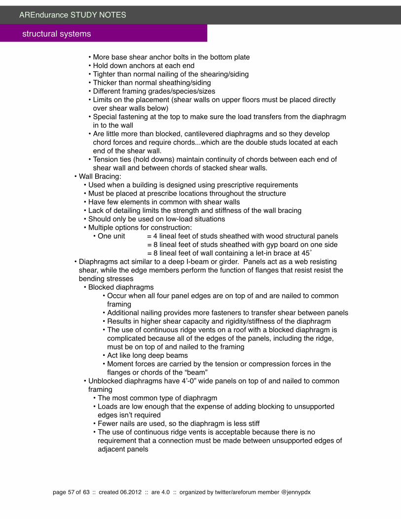
• More base shear anchor bolts in the bottom plate• Hold down anchors at each end• Tighter than normal nailing of the shearing/siding• Thicker than normal sheathing/siding• Different framing grades/species/sizes• Limits on the placement (shear walls on upper floors must be placed directly
over shear walls below)• Special fastening at the top to make sure the load transfers from the diaphragm
in to the wall• Are little more than blocked, cantilevered diaphragms and so they develop
chord forces and require chords...which are the double studs located at each end of the shear wall.
• Tension ties (hold downs) maintain continuity of chords between each end of shear wall and between chords of stacked shear walls.
• Wall Bracing:• Used when a building is designed using prescriptive requirements• Must be placed at prescribe locations throughout the structure • Have few elements in common with shear walls• Lack of detailing limits the strength and stiffness of the wall bracing• Should only be used on low-load situations • Multiple options for construction:
• One unit = 4 lineal feet of studs sheathed with wood structural panels " " " " = 8 lineal feet of studs sheathed with gyp board on one side " " " " = 8 lineal feet of wall containing a let-in brace at 45˚
• Diaphragms act similar to a deep I-beam or girder. Panels act as a web resisting shear, while the edge members perform the function of flanges that resist resist the bending stresses
• Blocked diaphragms • Occur when all four panel edges are on top of and are nailed to common
framing • Additional nailing provides more fasteners to transfer shear between panels • Results in higher shear capacity and rigidity/stiffness of the diaphragm• The use of continuous ridge vents on a roof with a blocked diaphragm is
complicated because all of the edges of the panels, including the ridge, must be on top of and nailed to the framing
• Act like long deep beams• Moment forces are carried by the tension or compression forces in the
flanges or chords of the “beam”• Unblocked diaphragms have 4’-0” wide panels on top of and nailed to common
framing • The most common type of diaphragm • Loads are low enough that the expense of adding blocking to unsupported
edges isn’t required• Fewer nails are used, so the diaphragm is less stiff• The use of continuous ridge vents is acceptable because there is no
requirement that a connection must be made between unsupported edges of adjacent panels
page 57 of 63 :: created 06.2012 :: are 4.0 :: organized by twitter/areforum member @jennypdx
AREndurance STUDY NOTES
structural systems

• Shear wall segments occur between openings in the shear wall. Only full height segments can be used to transfer the load from the diaphragm above to the floor below
• Codes define the minimum geometers and ratios that are tolerated • Base shear connections keep a building from sliding off its foundation
• When transferring shear between the second and first floor shear walls, wood structural panel sheathing will provide the transfer connection...provided that all the panel edges occur over and are attached to common framing
• At the foundation where the shear wall is fastened to the plate below, the base shear transfer is accomplished by bolting the plate down to the foundation
• When the building is bolted to the foundation, and can’t slide, then the force acting on the shear wall trying to overturn it becomes greater
• The taller the building the greater the force• Each shear wall segment is anchored to the foundation with tension ties called
“hold downs”• Drag Struts distribute the uniform diaphragm shear over the top of an opening for a
window or door in the the full height shear wall adjacent to them. • In residential construction, a double top plate typically acts as a drag strut• Also used to tie together different parts of an irregularly shaped building (L-
shaped or T-shaped) by dividing them into simple rectangles and connecting them with the drag struts
Concepts/Goals:• Connections are key to structure integrity• Wind and seismic forces are resisted by shear walls• Shear walls and diaphragms are building elements necessary for proper lateral design. • Shear walls are vertical and diaphragms are (or are close to) horizontal...but they
basically do the same thing• Diaphragm = simply supported beam• Shear wall = vertical, cantilevered diaphragm
• Foundations are a common area of structural weakness. • If they are porous or crumbly they won’t resist earthquakes/lateral forces• Cracks wider than 1/8” of an inch, large voids, “honeycomb” concrete, or concrete
that chips or flakes when poked are all signs of weak foundation
Implications of Design DecisionsConcepts/Goals:
• We engineer buildings so that life safety is assured during an earthquake or hurricane and so that structural damage is minimized
• The overall strength of a building is a function of the strength of individual building elements (walls, floors, roof, and foundation) and how they are tired together...it’s all in the connections.
• In a roof diaphragm to shear wall connection, for example, there is:• A vertical load trying to lift the roof away from the wall (wind uplift or vertical seismic
component)… AND... • A component of both high wind and seismic forces that tries to slide the roof in a
direction parallel to the axis of the wall... AND…
page 58 of 63 :: created 06.2012 :: are 4.0 :: organized by twitter/areforum member @jennypdx
AREndurance STUDY NOTES
structural systems

• A force is trying to push the wall into or away from the roof diaphragm in a direction perpendicular to the wall.
• The connection has to address all three…typically we use a framing anchor
Construction Details and Constructability Facts/Rules:
• Avoid using toenails when connecting diaphragms or shear walls together...they can’t resist force in all directions
• Remember, you have to address lateral forces in all three directions• So at every joint there will be forces trying to pull elements apart in all three
directions• Toenails are good at resisting loads only in certain directions (e.g.: perpendicular to
the plane of the nail, or sideways in relation to the nail)• Given the cyclic nature of earthquakes and hurricanes loads, direction of the load
“cycles” back and forth...this puts nails in withdrawal half the time, and nails never should bee used in withdrawal.
• Instead, use framing anchor. Catalogs typically give the capacity in all three directions
Construction MaterialsVocabulary:
• Load and Resistance Factor Design: a method of proportioning structural members and their connections using load and resistance factors such that no applicable limit state is reached when the structure is subjected to appropriate load combinations. Used in the design of steal and wood structures.
• Strength Design: method of proportioning structural members so that computed forces produced in the member by factored loads don’t exceed the member design length (LRFD). Used in the design of concrete and masonry structural elements
Facts/Rules:• 2 x 4 or 2 x 6 wood cross bracing and horizontal bracing is not strong enough to resist
lateral forces applied on a building’s foundation • Wood shear walls:
• Composed of wood structural sheathing fastened to wood framing and properly connected to the foundation below and the roof above
• Wood diaphragm:• Installation of wood structural panels over a roof or floor supports
• Anchor bolts are one of the most cost effective ways to protect a residential building from severe structural damage by securing the mud sill to the concrete foundation
• Bolts are typically placed 4’-0” to 6’-0” on center, 4” deep minimum, with an extra bolt within 9” - 12” of any joint, end plate, or step in the wall, with a minimum of two bolts per step
Concepts/Goals:• Wood’s flexibility allows the building better absorb and resist the forces found in both
earthquakes and high winds• Wood panels are a cost effective means for providing design requirements for shear
walls and diaphragms.
page 59 of 63 :: created 06.2012 :: are 4.0 :: organized by twitter/areforum member @jennypdx
AREndurance STUDY NOTES
structural systems

• Light framed wood structures are know as box type structures. Think of them like a simple corrugated cardboard box•Corrugation in the box sides are oriented vertically and have thus have a high
vertical load carrying capacity. This is similar to orientation of studs in a light framed wood wall•Each of the wall elements in the box is rigid...it’s hard to force a rectangular side of
the cardboard box “out of square” •Corrugation in the top and bottom of the box run from edge to edge, and vertical
loads applied to the op or bottom of the box are distributed to the sides. •Only when all the edges of the box are taped together does it gain its true potential
strength and ability to withstand lateral and vertical loads. •So in a building the “tape” is what allows the forces acting on one element to flow
into the adjacent elements all the way down to the ground• Structures that are bolted to foundation are still susceptible to lateral force of an
earthquakeIn wood frame construction, plywood sheets should be nailed to cripple walls which create shear panels that resist forces
page 60 of 63 :: created 06.2012 :: are 4.0 :: organized by twitter/areforum member @jennypdx
AREndurance STUDY NOTES
structural systems

VIGNETTE: STRUCTURAL LAYOUT
Steps1. Change layer to Upper Level and leave “Other Level” checked on View/Hide2. Insert columns in corners of Upper Level 3. If necessary, add additional columns so that maximum beam span is not exceeded4. Draw continuous beams that span the long direction of the wall5. Refer to max joist spacing and draw joists perpendicular to the beams6. Draw decking perpendicular to the joists7. Change layer to Lower Level and leave “Other Level” checked on View/Hide8. Add columns directly below columns on Upper Level9. Add columns to corners of Lower Level 10.Add any additional columns (align with those already drawn) so that maximum beam
span is not exceeded11.Draw continuous beams that span the long direction of the wall12.Refer to max joist spacing and draw joists perpendicular to the beams13.Draw decking perpendicular to the joists14. If a covered entry is included, draw any additional beams, joists, and decking15.Verify design with program…double check all requirements, then check again!
Tips· Maximum span for beams = 40’-0”· Maximum span for joists = 30’-0”· Additional columns (ie: those that aren’t in corners) on the upper floor should be
located over corners on the first floor so that framing is simplified· Draw beams in the centerline of the wall· Do not cantilever beams!!· Draw joists and decking to the centerline of the wall· Beams can’t transfer column loads… if there’s one above, there has to be one below· A beam is NOT required on the first floor so long as no joists are carried on it AND it is
an exterior wall. Perimeter walls can support upper levels without a beam. · A beam IS required at all places where an upper wall is supported, even if there isn’t a
partition below. · Columns support beams > beams support joists > joists support decking
page 61 of 63 :: created 06.2012 :: are 4.0 :: organized by twitter/areforum member @jennypdx
AREndurance STUDY NOTES
structural systems

REFERENCES
areforumARE Lateral Force Primer Last Updated March 5, 2012
APA -The Engineered Wood Association. Introduction to Lateral Design. 2003" http://www.areforum.org/up/Lateral%20Forces/APA%20intro%20LF%20X305.pdf
Brandon’s GS Notes (Ballast) from areforum FTP site" http://www.areforum.org/up/GeneralStructures/Brandon's%20GS%20notes" %20(Ballast)/
Common Trusses from the areforum FTP Site http://www.areforum.org/up/GeneralStructures/must%20read/CommonTrusses.pdf
Foundation Bolting from the areforum FTP site " http://www.areforum.org/up/Lateral%20Forces/4Bolt%20MUD%20SILL.pdf
Rich’s General Structural Study Notes from areforum FTP site" http://www.areforum.org/up/GeneralStructures/Rich's%20GS%20Study%20Notes.pdf
System Summary from the arefourm FTP sitehttp://www.areforum.org/up/GeneralStructures/system summary.rft
other websites“Construction Basics – Wind & Weather Resistance” by APA
http://www.apawood.org/level_b.cfm?content=app_bas_wind
How to Approach the Structural System Vignette by Dustin G Offron http://www.dustingoffron.com/ARE/HowtoApproachtheStructuralSystemsVignette.pdf
“Lecture 24 - Wind Load” by Assoc. Prof. Dave Hultenius. State University of New York @ Delhi http://faculty.delhi.edu/hultendc/AECT210-Lecture%2024.pdf
“Lecture 27 – Seismic Loads per IBC” by Assoc. Prof. Dave Hultenius. State University of New York @ Delhi http://faculty.delhi.edu/hultendc/AECT360-Lecture%2027.pdf
“Lumber Grading.” http://timber.ce.wsu.edu/Supplements/Production/grading.htm
“Structural Systems” http://www.bdcorr.ca.gov/cppd/more%20for%20less/4-c.pdf
“The Seismic Retrofit of Historic Buildings Keeping Preservation in the Forefront” by David W Look, AIA, Terry Wong, PE, and Silvia Rose Augustus. National Park Servicehttp://www.nps.gov/hps/tps/briefs/brief41.htm
“Wind Safety of the Building Envelope” by Tom Smith, AIA. Whole Building Design Guide http://www.wbdg.org/resources/env_wind.php
page 62 of 63 :: created 06.2012 :: are 4.0 :: organized by twitter/areforum member @jennypdx
AREndurance STUDY NOTES
structural systems

texts“Chapter 16”. 2006 International Building Code. International Code Council
Buildings At Risk: Seismic Design Basics for Practicing Architects. AIA/ACSA Council on Architectural Research. 1994.
"
page 63 of 63 :: created 06.2012 :: are 4.0 :: organized by twitter/areforum member @jennypdx
AREndurance STUDY NOTES
structural systems