contents 1 safety 2 mechanical installation 3 electrical ... 1.1.1 high voltage warning the voltage...
TRANSCRIPT

Contents
1 Safety 5
Safety instructions 5
Software Version and Approvals 6
General Warning 7
Avoid unintended Start 7
Before Commencing Repair Work 8
2 Mechanical Installation 9
Before Starting 9
Mechanical Dimensions 10
3 Electrical Installation 11
How to Connect 11
Electrical Installation in General 11
EMC-Correct Installation 12
Mains Connection 12
Motor Connection 13
Control Terminals 14
Connecting to Control Terminals 15
Switches 15
Power Circuit - Overview 15
Load sharing/Brake 16
4 Programming 17
How to Programme 17
Programming with MCT-10 Set-up Software 17
Programming with the LCP 11 or LCP 12 17
Status Menu 19
Quick Menu 19
Quick Menu Parameters 20
Main Menu 24
5 Modbus RTU 25
Modbus RTU Overview 25
Modbus RTU Message Framing Structure 26
Remote Terminal Unit 26
Modbus RTU Message Structure 26
Start/Stop Field 26
Address Field 27
Function Field 27
Data Field 27
VLT® Micro Drive FC 51 Operating Instructions Contents
MG.02.A4.02 - VLT® is a registered Danfoss trademark 1

CRC Check Field 27
Coil/Register Addressing 27
How to Control the frequency converter 29
Function Codes Supported by Modbus RTU 29
Exception and Error Codes 29
How to Access Parameters 30
Parameter Handling 30
Storage of Data 30
IND 30
Text Blocks 30
Conversion Factor 30
Parameter Values 30
Examples 30
Read Coil Status (01HEX) 31
Force/Write Single Coil (05HEX) 31
Force/Write Multiple Coils (0FHEX) 32
Read Holding Registers (03HEX) 32
Preset Single Register (06HEX) 33
Preset Multiple Registers (10HEX) 34
Danfoss FC Control Profile 35
Control Word According to FC Profile 35
Explanation of the Control Bits 35
Status Word According to FC Profile (STW) 37
Explanation of the Status Bits 38
Bus Speed Reference Value 39
6 Parameter Overview 41
Conversion Index 45
Change during operation 45
2-Set-up 45
Type 45
0-** Operation/Display 46
1-** Load/Motor 47
2-** Brakes 48
3-** Reference/Ramps 49
4-** Limits/Warnings 50
5-** Digital In/Out 51
6-** Analog In/Out 52
7-** Controllers 53
8-** Comm. and Options 54
13-** Smart Logic 55
Contents VLT® Micro Drive FC 51 Operating Instructions
2 MG.02.A4.02 - VLT® is a registered Danfoss trademark

14-** Special Functions 56
15-** Drive Information 57
16-** Data Readouts 58
7 Troubleshooting 59
Alarm, Warning and Extended Status Word 60
8 Specifications 61
Mains Supply 61
Other Specifications 63
Special Conditions 65
The Purpose of Derating 65
Derating for Ambient Temperature 65
Derating for Low Air Pressure 65
Derating for Running at Low Speeds 65
Options for VLT Micro Drive FC 51 66
Index 67
VLT® Micro Drive FC 51 Operating Instructions Contents
MG.02.A4.02 - VLT® is a registered Danfoss trademark 3

1 Safety VLT® Micro Drive FC 51 Operating Instructions
4 MG.02.A4.02 - VLT® is a registered Danfoss trademark
1

1 Safety
1.1.1 High Voltage Warning
The voltage of the frequency converter is dangerous whenever it is connected to mains. Incorrect installation of the motor or frequency
converter may cause damage to the equipment, serious injury or death. Consequently, it is essential to comply with the instructions
in this manual as well as local and national rules and safety regulations.
1.1.2 Safety instructions
Prior to using functions directly or indirectly influencing personal safety (e.g. Safe Stop, Fire Mode or other functions either forcing
the motor to stop or attempting to keep it functioning) a thorough risk analysis and system test must be carried through. The
system tests must include testing failure modes regarding the control signalling (analog and digital signals and serial communication.
NB!
Before using Fire Mode, contact Danfoss
• Make sure the frequency converter is properly connected to earth.
• Do not remove mains connections, motor connections or other power connections while the frequency converter is connected to power.
• Protect users against supply voltage.
• Protect the motor against overloading according to national and local regulations.
• The earth leakage current exceeds 3.5 mA.
• The [OFF] key is not a safety switch. It does not disconnect the frequency converter from mains.
VLT® Micro Drive FC 51 Operating Instructions 1 Safety
MG.02.A4.02 - VLT® is a registered Danfoss trademark 5
1

1.1.3 Software Version and Approvals
Software VersionOperating Instructions
VLT Micro DriveFC 51 Series
This Operating Instructions
can be used for all VLT MicroDrive FC 51 frequency con-
verters with software version2.2x.
The software version numbercan be read in
parameter 15-43.
1 Safety VLT® Micro Drive FC 51 Operating Instructions
6 MG.02.A4.02 - VLT® is a registered Danfoss trademark
1
1.1.4 General Warning
Warning:
Touching the electrical parts may be fatal - even after the equipment has been disconnected from mains.
Also make sure that other voltage inputs have been disconnected (linkage of DC intermediate circuit).
Be aware that there may be high voltage on the DC link even when the LEDs are turned off.
Before touching any potentially live parts of the frequency converter, wait at least 4 minutes for all sizes.
Shorter time is allowed only if indicated on the nameplate for the specific unit.
Leakage Current
The earth leakage current from the frequency converter exceeds 3.5 mA. According to IEC 61800-5-1 a reinforced Protective Earth
connection must be ensured by means of a min. 10mm² Cu or an addtional PE wire - with the same cable cross section as the Mains
wiring - must be terminated separately.
Residual Current Device
This product can cause a DC current in the protective conductor. Where a residual current device (RCD) is used for extra protection,
only an RCD of Type B (time delayed) shall be used on the supply side of this product. See also Danfoss Application Note on RCD, MN.
90.GX.YY.
Protective earthing of the frequency converter and the use of RCDs must always follow national and local regulations.
Motor overload protection is possible by setting Parameter 1-90 Motor thermal protection to the value ETR trip. For the North American
market: ETR functions provide class 20 motor overload protection, in accordance with NEC.
Installation in high altitudes:
For altitudes above 2 km, please contact Danfoss regarding PELV.
1.1.5 IT Mains
IT Mains
Installation on isolated mains source, i.e. IT mains.
Max. supply voltage allowed when connected to mains: 440 V.
As an option, Danfoss offers line filters for improved harmonics performance.
1.1.6 Avoid unintended Start
While the frequency converter is connected to mains, the motor can be started/stopped using digital commands, bus commands, references or via the
Local Control Panel.
• Disconnect the frequency converter from mains whenever personal safety considerations make it necessary to avoid unintended start of any
motors.
• To avoid unintended start, always activate the [OFF] key before changing parameters.
VLT® Micro Drive FC 51 Operating Instructions 1 Safety
MG.02.A4.02 - VLT® is a registered Danfoss trademark 7
1

1.1.7 Disposal instruction
Equipment containing electrical components must not be disposed of together with domestic waste.It must be separately collected with electrical and electronic waste according to local and currently valid leg-islation.
1.1.8 Before Commencing Repair Work
1. Disconnect FC 51 from mains (and external DC supply, if present.)
2. Wait for 4 minutes for discharge of the DC-link.
3. Disconnect DC bus terminals and brake terminals (if present)
4. Remove motor cable
1 Safety VLT® Micro Drive FC 51 Operating Instructions
8 MG.02.A4.02 - VLT® is a registered Danfoss trademark
1

2 Mechanical Installation
2.1 Before Starting
2.1.1 Checklist
When unpacking the frequency converter, make sure that the unit is un-
damaged and complete. Check that the packaging contains the following:
• VLT Micro Drive FC 51
• Quick Guide
Optional: LCP and/or de-coupling plate.
Illustration 2.1: Content of box.
2.2 Side-by-Side InstallationThe frequency converter can be mounted side-by-side for IP 20 rating units and requires 100 mm clearance above and below for cooling. Regarding
surroundings in general, please see chapter 7. Specifications.
Illustration 2.1: Side-by-side installation.
VLT® Micro Drive FC 51 Operating Instructions 2 Mechanical Installation
MG.02.A4.02 - VLT® is a registered Danfoss trademark 9
2

2.3.1 Mechanical Dimensions
Illustration 2.1: Mechanical dimensions.
NB!
A template for drilling can be found on the flap of the packaging.
Power (kW) Height (mm) Width (mm) Depth 1)
(mm)Max.Weight
Frame 1 X 200-240V
3 X200 -240 V
3 X380-480 V A A (incl. decou-
pling plate) a B b C Kg
M1 0.18 - 0.75 0.25 - 0.75 0.37 - 0.75 150 205 140.4 70 55 148 1.1M2 1.5 1.5 1.5 - 2.2 176 230 166.4 75 59 168 1.6M3 2.2 2.2 -3.7 3.0 - 7.5 239 294 226 90 69 194 3.0
Table 2.1: Mechanical Dimensions
1) For LCP with potentiometer, please add 7.6 mm.
NB!
DIN rail mounting kit is available for M1 frame . Please use ordering number 132B0111.
2 Mechanical Installation VLT® Micro Drive FC 51 Operating Instructions
10 MG.02.A4.02 - VLT® is a registered Danfoss trademark
2

3 Electrical Installation
3.1 How to Connect
3.1.1 Electrical Installation in General
NB!
All cabling must comply with national and local regulations on cable cross-sections and ambient temperature. Copper conductors
required, (60-75° C) recommended.
Details of terminal tightening torques.
Power (kW) Torque (Nm)
Frame 1 x 200-240V
3 x 200-240V
3 x 380-480V Line Motor
DC connec-tion/Brake1)
Control Ter-minals Earth Relay
M1 0.18 - 0.75 0.25 - 0.75 0.37 - 0.75 1.4 0.7 - 0.15 3 0.5M2 1.5 1.5 1.5 - 2.2 1.4 0.7 - 0.15 3 0.5M3 2.2 2.2 - 3.7 3.0 - 7.5 1.4 0.7 - 0.15 3 0.5
1) Spade connectors (6.3 mm Faston plugs)
Table 3.1: Tightening of terminals.
3.1.2 Fuses
Branch circuit protection:
In order to protect the installation against electrical and fire hazard, all branch circuits in an installation, switch gear, machines etc., must be short-circuited
and overcurrent protected according to national/international regulations.
Short circuit protection:
Danfoss recommends using the fuses mentioned in the following tables to protect service personnel or other equipment in case of an internal failure in
the unit or short-circuit on DC-link. The frequency converter provides full short circuit protection in case of a short-circuit on the motor or brake output.
a circuit capable of supplying a maximum of 100,000 Arms (symmetrical), 480 V maximum.
Overcurrent protection:
Provide overload protection to avoid overheating of the cables in the installation. Overcurrent protection must always be carried out according to national
regulations. Fuses must be designed for protection in a circuit capable of supplying a maximum of 100,000 Arms (symmetrical), 480 V maximum.
Non UL compliance:
If UL/cUL is not to be complied with, Danfoss recommends using the fuses mentioned in the below table, which will ensure compliance with EN50178/
IEC61800-5-1:
In case of malfunction, not following the fuse recommendation may result in damage to the frequency converter.
VLT® Micro Drive FC 51 Operating Instructions 3 Electrical Installation
MG.02.A4.02 - VLT® is a registered Danfoss trademark 11
3

FC 51UL
Max. fuses non ULBussmann Bussmann Bussmann Littel fuse Ferraz-Shawmut
Ferraz-Shawmut
1 X 200-240 VkW Type RK1 Type J Type T Type RK1 Type CC Type RK1 Type gG0K18 - 0K37 KTN-R15 JKS-15 JJN-15 KLN-R15 ATM-R15 A2K-15R 15A0K75 KTN-R25 JKS-25 JJN-25 KLN-R25 ATM-R25 A2K-25R 25A1K5 KTN-R35 JKS-35 JJN-35 KLN-R35 - A2K-35R 35A2K2 KTN-R45 JKS-45 JJN-45 KLN-R45 - A2K-45R 45A3 x 200-240 V0K25 KTN-R10 JKS-10 JJN-10 KLN-R10 ATM-R10 A2K-10R 10A0K37 KTN-R15 JKS-15 JJN-15 KLN-R15 ATM-R15 A2K-15R 15A0K75 KTN-R20 JKS-20 JJN-20 KLN-R20 ATM-R20 A2K-20R 20A1K5 KTN-R25 JKS-25 JJN-25 KLN-R25 ATM-R25 A2K-25R 25A2K2 KTN-R40 JKS-40 JJN-40 KLN-R40 ATM-R40 A2K-40R 40A3K7 KTN-R40 JKS-40 JJN-40 KLN-R40 - A2K-40R 40A3 x 380-480 V0K37 - 0K75 KTS-R10 JKS-10 JJS-10 KLS-R10 ATM-R10 A6K-10R 10A1K5 KTS-R15 JKS-15 JJS-15 KLS-R15 ATM-R15 A2K-15R 15A2K2 KTS-R20 JKS-20 JJS-20 KLS-R20 ATM-R20 A6K-20R 20A3K0 KTS-R40 JKS-40 JJS-40 KLS-R40 ATM-R40 A6K405R 40A4K0 KTS-R40 JKS-40 JJS-40 KLS-R40 ATM-R40 A6K-40R 40A5K5 KTS-R40 JKS-40 JJS-40 KLS-R40 - A6K-40R 40A7K5 KTS-R40 JKS-40 JJS-40 KLS-R40 - A6K-40R 40A
Table 3.3: Fuses
3.1.3 EMC-Correct Installation
Following these guidelines is advised, where compliance with EN 61000-6-3/4, EN 55011 or EN 61800-3 First environment is required. If the installation
is in EN 61800-3 Second environment, then it is acceptable to deviate from these guidelines. It is however not recommended.
Good engineering practice to ensure EMC-correct electrical installation:
• Use only braided screened/armoured motor cables and control cables.
The screen should provide a minimum coverage of 80%.The screen material must be metal, not limited to but typically copper, aluminium, steel
or lead. There are no special requirements for the mains cable.
• Installations using rigid metal conduits are not required to use screened cable, but the motor cable must be installed in conduit separate from
the control and mains cables. Full connection of the conduit from the drive to the motor is required. The EMC performance of flexible conduits
varies a lot and information from the manufacturer must be obtained.
• Connect the screen/armour/conduit to earth at both ends for motor cables and control cables.
• Avoid terminating the screen/armour with twisted ends (pigtails). Such a termination increases the high frequency impedance of the screen,
which reduces its effectiveness at high frequencies. Use low impedance cable clamps or glands instead.
• Ensure good electrical contact between the de-coupling plate and the metal chassis of the frequency converter, see Instruction MI.02.BX.YY.
• Avoid using unscreened/unarmoured motor or control cables inside cabinets housing the drive(s), where possible.
3.2 Mains Connection
3.2.1 Connecting to Mains
Step 1: First mount earth cable.
Step 2: Mount wires in terminals L1/L, L2 and L3/N and tighten.
Illustration 3.1: Mounting of earth cable and mains wires.
3 Electrical Installation VLT® Micro Drive FC 51 Operating Instructions
12 MG.02.A4.02 - VLT® is a registered Danfoss trademark
3
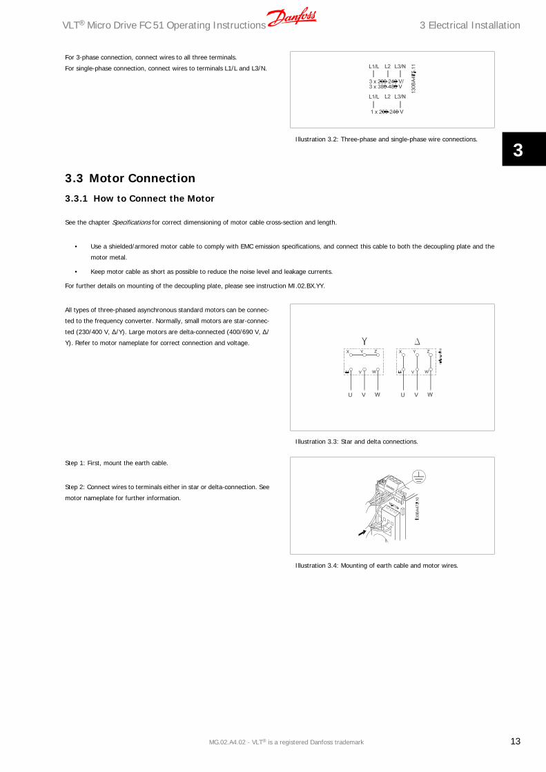
For 3-phase connection, connect wires to all three terminals.
For single-phase connection, connect wires to terminals L1/L and L3/N.
Illustration 3.2: Three-phase and single-phase wire connections.
3.3 Motor Connection
3.3.1 How to Connect the Motor
See the chapter Specifications for correct dimensioning of motor cable cross-section and length.
• Use a shielded/armored motor cable to comply with EMC emission specifications, and connect this cable to both the decoupling plate and the
motor metal.
• Keep motor cable as short as possible to reduce the noise level and leakage currents.
For further details on mounting of the decoupling plate, please see instruction MI.02.BX.YY.
All types of three-phased asynchronous standard motors can be connec-
ted to the frequency converter. Normally, small motors are star-connec-
ted (230/400 V, Δ/Y). Large motors are delta-connected (400/690 V, Δ/
Y). Refer to motor nameplate for correct connection and voltage.
Illustration 3.3: Star and delta connections.
Step 1: First, mount the earth cable.
Step 2: Connect wires to terminals either in star or delta-connection. See
motor nameplate for further information.
Illustration 3.4: Mounting of earth cable and motor wires.
VLT® Micro Drive FC 51 Operating Instructions 3 Electrical Installation
MG.02.A4.02 - VLT® is a registered Danfoss trademark 13
3

For EMC correct installation, use optional de-coupling plate, see chapter
Options for frequency converter.
Illustration 3.5: Frequency converter with de-coupling plate
3.4 Control Terminals
3.4.1 Access to Control Terminals
All control cable terminals are located underneath the terminal cover in
front of the frequency converter. Remove the terminal cover using a
screwdriver.
Illustration 3.6: Removing terminal cover.
NB!
See back of terminal cover for outlines of control terminals and switches.
3 Electrical Installation VLT® Micro Drive FC 51 Operating Instructions
14 MG.02.A4.02 - VLT® is a registered Danfoss trademark
3

3.4.2 Connecting to Control Terminals
This illustration shows all control terminals of the frequency converter. Applying Start (term. 18) and an analog reference (term. 53 or 60) make the
frequency converter run.
Illustration 3.7: Overview of control terminals in PNP-configuration and factory setting.
3.5 Switches
NB!
Do not operate switches with power on the frequency converter.
Bus termination:
Switch BUS TER pos. ON terminates the RS485 port, terminals 68, 69.
See power circuit drawing.
Default setting = Off.
Illustration 3.8: S640 Bus termination.
S200 Switches 1-4:
Switch 1: *OFF = PNP terminals 29
ON = NPN terminals 29
Switch 2: *OFF = PNP terminal 18, 19, 27 and 33
ON = NPN terminal 18, 19, 27 and 33
Switch 3: No function
Switch 4: *OFF = Terminal 53 0 - 10 V
ON = Terminal 53 0/4 - 20 mA
* = default setting
Table 3.5: Settings for S200 Switches 1-4
Illustration 3.9: S200 Switches 1-4.
NB!
Parameter 6-19 must be set according to Switch 4 po-
sition.
VLT® Micro Drive FC 51 Operating Instructions 3 Electrical Installation
MG.02.A4.02 - VLT® is a registered Danfoss trademark 15
3

3.6 Power Circuit - Overview
3.6.1 Power Circuit - Overview
Illustration 3.10: Diagram showing all electrical terminals.
Brake not applicable for frame M1.
Brake resistors are available from Danfoss.
Improved power factor and EMC performance can be achieved by installing optional Danfoss line filters.
Danfoss power filters can also be used for load sharing.
3.6.2 Load sharing/Brake
Use 6.3 mm insulated Faston Plugs designed for high voltage for DC (Load Sharing and brake).
Contact Danfoss or see instruction no. MI.50.Nx.02 for load sharing and instruction no. MI.90.Fx.02 for brake.
Load sharing: Connect terminals UDC- and UDC/BR+.
Brake: Connect terminals BR- and UDC/BR+.
Note that voltage levels of up to 850 V DC may occur between terminals
UDC+/BR+ and UDC-. Not short circuit protected.
3 Electrical Installation VLT® Micro Drive FC 51 Operating Instructions
16 MG.02.A4.02 - VLT® is a registered Danfoss trademark
3

4 Programming
4.1 How to Programme
4.1.1 Programming with MCT-10 Set-up Software
The frequency converter can be programmed from a PC via RS485 com-port by installing the MCT-10 Set-up Software.
This software can either be ordered using code number 130B1000 or downloaded from the Danfoss Web site: www.danfoss.com, Business Area: Motion
Controls.
Please refer to manual MG.10.RX.YY.
4.1.2 Programming with the LCP 11 or LCP 12
The LCP is divided into four functional groups:
1. Numeric display.
2. Menu key.
3. Navigation keys.
4. Operation keys and indicator lights (LEDs).
Illustration 4.1: LCP 12 with potentiometer
Illustration 4.2: LCP 11 without potentiometer
The display:
A number of information can be read from the display.
Set-up number shows the active set-up and the edit set-up. If the same
set-up acts as both active and edit set-up, only that set-up number is
shown (factory setting).
When active and edit set-up differ, both numbers are shown in the display
(Setup 12). The number flashing, indicates the edit set-up.
Illustration 4.3: Indicating Set-up
VLT® Micro Drive FC 51 Operating Instructions 4 Programming
MG.02.A4.02 - VLT® is a registered Danfoss trademark 17
4

The small digits to the left are the selected parameter number.
Illustration 4.4: Indicating selected par. no.
The large digits in the middle of the display show the value of the se-
lected parameter.
Illustration 4.5: Indicating value of selected par.
The right side of the display shows the unit of the selected parameter.
This can be either Hz, A, V, kW, HP, %, s or RPM.
Illustration 4.6: Indicating unit of selected par.
Motor direction is shown to the bottom left of the display - indicated
by a small arrow pointing either clockwise or counterclockwise.
Illustration 4.7: Indicating motor direction
Use the [MENU] key to select one of the following menus:
Status Menu:
The Status Menu is either in Readout Mode or Hand on Mode. In Readout Mode the value of the currently selected readout parameter is shown in the
display.
In Hand on Mode the local LCP reference is displayed.
Quick Menu:
Displays Quick Menu parameters and their settings. Parameters in the Quick Menu can be accessed and edited from here. Most applications can be run
by setting the parameters in the Quick Menus.
Main Menu:
Displays Main Menu parameters and their settings. All parameters can be accessed and edited here. A parameter overview is found later in this manual.
Indicator lights:
• Green LED: The frequency converter is on.
• Yellow LED: Indicates a warning. Please see section Troubleshooting
• Flashing red LED: Indicates an alarm. Please see section Troubleshooting
4 Programming VLT® Micro Drive FC 51 Operating Instructions
18 MG.02.A4.02 - VLT® is a registered Danfoss trademark
4

Navigation Keys:
[Back]: For moving to the previous step or layer in the navigation structure.
Arrows [] []: For maneuvering between parameter groups, parameters and within parameters.
[OK]: For selecting a parameter and for accepting changes to parameter settings.
Operation Keys:
A yellow light above the operation keys indicates the active key.
[Hand on]: Starts the motor and enables control of the frequency converter via the LCP.
[Off/Reset]: The motor stops except in alarm mode. In that case the motor will be reset.
[Auto on]: The frequency converter is controlled either via control terminals or serial communication.
[Potentiometer] (LCP12): The potentiometer works in two ways depending on the mode in which the frequency converter is running.
In Auto Mode the potentiometer acts as an extra programmable analog input.
In Hand on Mode the potentiometer controls local reference.
4.2 Status MenuAfter power up the Status Menu is active. Use the [MENU] key to toggle
between Status, Quick Menu and Main Menu.
Arrows [] and [] toggles between the choices in each menu.
The display indicates the status mode with a small arrow above “Status”.
Illustration 4.8: Indicating Status mode
4.3 Quick MenuThe Quick Menu gives easy access to the most frequently used parameters.
1. To enter the Quick Menu, press [MENU] key until indicator in display is placed above Quick Menu.
2. Use [] [] to select either QM1 or QM2, then press [OK].
3. Use [] [] to browse through the parameters in the Quick Menu.
4. Press [OK] to select a parameter.
5. Use [] [] to change the value of a parameter setting.
6. Press [OK] to accept the change.
7. To exit, press either [Back] twice to enter Status, or press [Menu] once to enter Main Menu.
Illustration 4.9: Indicating Quick Menu mode
VLT® Micro Drive FC 51 Operating Instructions 4 Programming
MG.02.A4.02 - VLT® is a registered Danfoss trademark 19
4

4.4 Quick Menu Parameters
4.4.1 Quick Menu Parameters - Basic Settings QM1
Below are descriptions of all parameters found in the Quick Menu.
* = Factory setting.
1-20 Motor Power [kW]/[HP] (Pm.n)
Option: Function:Enter motor power from nameplate data.
Two sizes down, one size up from nominal VLT rating.
[1] 0.09 kW/0.12 HP
[2] 0.12 kW/0.16 HP
[3] 0.18kW/0.25 HP
[4] 0.25 kW/0.33 HP
[5] 0.37kW/0.50 HP
[6] 0.55 kW/0.75 HP
[7] 0.75 kW/1.00 HP
[8] 1.10 kW/1.50 HP
[9] 1.50 kW/2.00 HP
[10] 2.20 kW/3.00 HP
[11] 3.00 kW/4.00 HP
[12] 3.70 kW/5.00 HP
[13] 4.00 kW/5.40 HP
[14] 5.50 kW/7.50 HP
[15] 7.50 kW/10.0 HP
[16] 11.00 kW/15.00 HP
NB!
Changing this parameter affects par. 1-22 to 1-25,
1-30, 1-33 and 1-35.
1-22 Motor Voltage (U m.n)
Range: Function:230/400 V [50 - 999 V] Enter motor voltage from nameplate data.
1-23 Motor Frequency (f m.n)
Range: Function:50 Hz* [20-400 Hz] Enter motor frequency from nameplate data.
4 Programming VLT® Micro Drive FC 51 Operating Instructions
20 MG.02.A4.02 - VLT® is a registered Danfoss trademark
4

1-24 Motor Current (I m.n)
Range: Function:M-type de-
pendent*
[0.01 - 26.00 A] Enter motor current from nameplate data.
1-25 Motor Nominal Speed (n m.n)
Range: Function:M-type De-
pendent*
[100 - 9999 RPM] Enter motor nominal speed from nameplate data.
1-29 Automatic Motor Tuning (AMT)
Option: Function:Use AMT to optimize motor performance.
NB!
This parameter cannot be changed while motor runs.
1. Stop the frequency converter – make sure motor is at standstill
2. Choose [2] Enable AMT
3. Apply start signal
– Via LCP: Press Hand On
- Or in Remote On mode: Apply start signal on terminal 18
[0] * Off AMT function is disabled.
[2] Enable AMT AMT function starts running.
NB!
To gain optimum tuning of frequency converter, run AMT on a cold motor.
3-02 Minimum Reference
Range: Function:0.00* [-4999 - 4999] Enter value for minimum reference.
The sum of all internal and external references are clamped (limited) to the minimum reference
value, par. 3-02.
3-03 Maximum Reference
Range: Function:Maximum Reference is adjustable in the range Minimum Reference - 4999.
50.00* [-4999 - 4999] Enter value for Maximum Reference.
The sum of all internal and external references are clamped (limited) to the maximum reference
value, par. 3-03.
VLT® Micro Drive FC 51 Operating Instructions 4 Programming
MG.02.A4.02 - VLT® is a registered Danfoss trademark 21
4

3-41 Ramp1 Ramp-up Time
Range: Function:3.00 s* [0.05 - 3600.00 s ] Enter ramp-up time from 0 Hz to rated motor frequency (fM,N) set in par. 1-23.
Choose a ramp-up time ensuring that torque limit is not exceeded, see par. 4-16.
3-42 Ramp1 Ramp-down Time
Range: Function:3.00* [0.05 - 3600.00 s] Enter ramp down time from rated motor frequency (fM,N) in par. 1-23 to 0 Hz.
Choose a ramp down time that does not cause over-voltage in inverter due to regenerative operation
of motor. Furthermore, regenerative torque must not exceed limit set in par. 4-17.
4.4.2 Quick Menu Parameters - PI Basic Settings QM2
The following is a brief description of the parameters for the PI Basic Settings. For a more detailed description, please see VLT Micro Drive Programming
Guide, MG.02.CX.YY.
1-00 Configuration Mode
Range: Function: [] Choose [3] Process Closed Loop
3-02 Min. Reference
Range: Function: [-4999 - 4999] Sets limits for set-point and feedback.
3-03 Max. Reference
Range: Function: [-4999 - 4999] Sets limits for set-point and feedback.
3-10 Preset Reference
Range: Function: [-100.00 - 100.00] Preset [0] works as set-point.
4-12 Motor Speed Low Limit
Range: Function: [0.0 - 400 Hz] Lowest possible output frequency.
4-14 Motor Speed High Limit
Range: Function: [0.0 - 400.00 Hz] Highest possible output frequency.
NB!
Default 65 Hz should normally be reduced to 50 - 55 Hz.
4 Programming VLT® Micro Drive FC 51 Operating Instructions
22 MG.02.A4.02 - VLT® is a registered Danfoss trademark
4

6-22 Terminal 60 Low Current
Range: Function: [0.00 - 19.99 mA] Normally set to 0 or 4 mA.
6-23 Terminal 60 High Current
Range: Function: [0.01 - 20.00 mA] Normally (default) set to 20 mA.
6-24 Terminal 60 Low Feedback Value
Range: Function: [-4999 - 4999] Value corresponding to P. 6-22 setting.
6-25 Terminal 60 High Feedback Value
Range: Function: [-4999 - 4999] Value corresponding to P. 6-23 setting.
6-26 Terminal 60 Filter Time Constant
Range: Function: [0.01 - 10.00 s] Filter for suppressing electrical noise.
7-20 Process CL Feedback Resource
Range: Function: [] Choose [2] analog input 60.
7-30 Process PI Normal/Inverse
Range: Function: [] Most PI controllers are “Normal”.
7-31 Process PI Anti Windup
Range: Function: [] Leave Enabled normally.
7-32 Process PI Start Speed
Range: Function: [0.0 - 200.0 Hz] Choose expected normal running speed.
7-33 Process PI Proportional Gain
Range: Function: [0.00 - 10.00] Enter the P-factor.
7-34 Process PI Integral Time
Range: Function: [0.10 - 9999.00 s] Enter the I-factor.
VLT® Micro Drive FC 51 Operating Instructions 4 Programming
MG.02.A4.02 - VLT® is a registered Danfoss trademark 23
4

7-38 Process Feed Forward Factor
Range: Function: [0 - 400%] Only applicable with changing set-points.
4.5 Main Menu
The Main Menu gives access to all parameters.
1. To enter the Main Menu, press [MENU] key until indicator in
display is placed above Main Menu.
2. Use [] [] to browse through the parameter groups.
3. Press [OK] to select a parameter group.
4. Use [] [] to browse through the parameters in the specific
group.
5. Press [OK] to select the parameter.
6. Use [] [] to set/change the parameter value.
7. Press [OK] to accept the value.
8. To exit, press either [Back] twice to enter Quick Menu, or press
[Menu] once to enter Status.
Illustration 4.10: Indicating Main Menu mode
4 Programming VLT® Micro Drive FC 51 Operating Instructions
24 MG.02.A4.02 - VLT® is a registered Danfoss trademark
4

5 Modbus RTU
5.1 Modbus RTU Overview
5.1.1 Assumptions
These operating instructions assume that the installed controller supports the interfaces in this document and that all the requirements stipulated in the
controller, as well as the frequency converter, are strictly observed, along with all limitations therein.
5.1.2 What the User Should Already Know
The Modbus RTU (Remote Terminal Unit) is designed to communicate with any controller that supports the interfaces defined in this document. It is
assumed that the user has full knowledge of the capabilities and limitations of the controller.
5.1.3 Modbus RTU Overview
Regardless of the type of physical communication networks, the Modbus RTU Overview describes the process a controller uses to request access to
another device. This includes i.a. how it will respond to requests from another device, and how errors will be detected and reported. It also establishes
a common format for the layout and contents of message fields.
During communications over a Modbus RTU network, the protocol determines how each controller will learn its device address, recognise a message
addressed to it, determine the kind of action to be taken, and extract any data or other information contained in the message. If a reply is required, the
controller will construct the reply message and send it.
Controllers communicate using a master-slave technique in which only one device (the master) can initiate transactions (called queries). The other devices
(slaves) respond by supplying the requested data to the master, or by taking the action requested in the query.
The master can address individual slaves, or can initiate a broadcast message to all slaves. Slaves return a message (called a response) to queries that
are addressed to them individually. No responses are returned to broadcast queries from the master. The Modbus RTU protocol establishes the format
for the master’s query by placing into it the device (or broadcast) address, a function code defining the requested action, any data to be sent, and an
error-checking field. The slave’s response message is also constructed using Modbus protocol. It contains fields confirming the action taken, any data to
be returned, and an error-checking field. If an error occurs in receipt of the message, or if the slave is unable to perform the requested action, the slave
will construct an error message and send it in response, or a time-out will occur.
5.1.4 Frequency Converter with Modbus RTU
The frequency converter communicates in Modbus RTU format over the built-in RS-485 interface. Modbus RTU provides access to the Control Word and
Bus Reference of the frequency converter.
The Control Word allows the Modbus master to control several important functions of the frequency converter:
• Start
• Stop of the frequency converter in various ways:
Coast stop
Quick stop
DC Brake stop
Normal (ramp) stop
• Reset after a fault trip
• Run at a variety of preset speeds
• Run in reverse
• Change the active set-up
• Control the frequency converter’s built-in relay
The Bus Reference is commonly used for speed control. It is also possible to access the parameters, read their values, and where possible, write values
to them. This permits a range of control options, including controlling the setpoint of the frequency converter when its internal PI controller is used.
VLT® Micro Drive FC 51 Operating Instructions 5 Modbus RTU
MG.02.A4.02 - VLT® is a registered Danfoss trademark 25
5

5.2 Modbus RTU Message Framing Structure
5.2.1 Remote Terminal Unit
The controllers are set up to communicate on the Modbus network using RTU (Remote Terminal Unit) mode, with each 8-bit byte in a message containing
two 4-bit hexadecimal characters.
The format for each byte is shown below.
Start bit Data bit Stop/parity Stop
Coding system: 8-bit binary, hexadecimal 0-9, A-F. Two hexadecimal characters contained in each 8-bit field of
the message.
Bits per byte: 1 start bit
8 data bits, least significant bit sent first
Parity: 1 bit for even/odd parity is used; 1 or 2 stop bits if no parity is selected (see par. 8-33).
Error Check Field: Cyclical Redundancy Check (CRC).
5.2.2 Modbus RTU Message Structure
The transmitting device places a Modbus RTU message into a frame with a known beginning and ending point. This allows receiving devices to begin at
the start of the message, read the address portion, determine which device is addressed (or all devices, if the message is broadcast), and to recognise
when the message is completed. Partial messages are detected and errors set as a result - or timeouts occur. Characters for transmission must be in
hexadecimal 00 to FF format in each field.
The frequency converter continuously monitors the network bus, also during “silent” intervals. When the first field (the address field) is received, each
frequency converter or device decodes it to determine which device is being addressed. Modbus RTU messages addressed to zero are broadcast messages.
No response is permitted for boradcast messages. A typical message frame is shown below.
Start Address Function Data CRC check End
T1-T2-T3-T4 1 byte 1 byte N x 1 byte 2 bytes T1-T2-T3-T4
Table 5.1: Typical Modbus RTU Message Structure
5.2.3 Start/Stop Field
Messages start with a silent period of at least 3.5 character intervals. This is implemented as a multiple of character intervals at the selected network
baud rate (shown as Start T1-T2-T3-T4). The first field to be transmitted is the device address. Following the last transmitted character, a similar period
of at least 3.5 character intervals marks the end of the message. A new message can begin after this period.
The entire message frame must be transmitted as a continuous stream. If a silent period of more than 1.5 character intervals occurs before completion
of the frame, the receiving device flushes the incomplete message and assumes that the next byte will be the address field of a new message. Similarly,
if a new message begins prior to 3.5 character intervals after a previous message, the receiving device will ignore both messages. This will cause a time-
out (no response from the slave).
5 Modbus RTU VLT® Micro Drive FC 51 Operating Instructions
26 MG.02.A4.02 - VLT® is a registered Danfoss trademark
5

5.2.4 Address Field
The address field of a message frame contains 1 byte. Valid slave device addresses are in the range of 0 - 247 decimal. The individual slave devices are
assigned addresses in the range of 1 - 247 (0 is reserved for broadcast mode, which all slaves recognise). A master addresses a slave by placing the
slave address in the address field of the message.
When the slave sends its response, it places its own address in this address field to let the master know which slave is responding.
5.2.5 Function Field
The function field of a message frame contains 1 byte. Function fields are used to send messages between master and slave. When a message is sent
from a master to a slave device, the function code field tells the slave what kind of action to perform. When the slave responds to the master, it uses the
function code field to indicate either a normal (error-free) response, or that some kind of error occurred (called an exception response).
For a normal response, the slave simply echoes the original function code. For an exception response, the slave returns a code that is equivalent to the
original code with its most significant bit set to logic 1. In addition, the slave places a unique code into the data field of the response message. This tells
the master what kind of error occurred, or the reason for the exception. Please also refer to the sections Function Codes Supported by Modbus RTU and
Exception Codes.
5.2.6 Data Field
The data field is constructed using sets of two hexidecimal digits in the range of 00 to FF hexidecimal. These are made up of one RTU character. The
data field of messages sent from a master to a slave device contains additional information which the slave must use to take the action defined by the
function code. This can include items such as addresses of coils or registers, the quantity of items to be handled. and the count of actual data bytes in
the field.
5.2.7 CRC Check Field
Messages include an error-checking field, operating on the basis of a Cyclical Redundancy Check (CRC) method. The CRC field checks the content of the
entire message. It is applied regardless of any parity check method used for the individual characters of the message.
The CRC value is calculated by the transmitting device, which appends the CRC as the last field in the message. The receiving device recalculates a CRC
during receipt of the message and compares the calculated value to the actual value received in the CRC field. If the two values are unequal, a bus time-
out occurs. The error-checking field contains a 16-bit binary value implemented as two 8-bit bytes. When this is done, the low-order byte of the field is
appended first, followed by the high-order byte. The CRC high-order byte is the last byte sent in the message.
5.2.8 Coil/Register Addressing
In Modbus, all data are organised in coils and holding registers. Coils hold a single bit, whereas holding registers hold a 2-byte word (i.e. 16 bits). All
data addresses in Modbus messages are referenced to zero. The first occurrence of a data item is addressed as item number zero.
Example:
The coil known as “coil 1” in programmable controller is addressed as coil 0000 in the data address field of a Modbus message. Coil 127 decimal is
addressed as coil 007EHEX (126 decimal).
Holding register 40001 is addressed as register 0000 in the data address field of the message. The function code field already specifies a “holding register”
operation. Therefore, the “4XXXX” reference is implicit. Holding register 40108 is addressed as register 006BHEX (107 decimal).
VLT® Micro Drive FC 51 Operating Instructions 5 Modbus RTU
MG.02.A4.02 - VLT® is a registered Danfoss trademark 27
5

Coil number Description Signal direction
1 - 16 Frequency converter control word (see table below) Master to slave
17 - 32 Frequency converter speed or set-point reference
Range 0x0 - 0xFFFF (-200% ... ~ 200%)
Master to slave
33 - 48 Frequency converter status word (see table below) Slave to master
49 - 64 Open loop mode: Frequency converter output fre-
quency
Closed loop mode: Frequency converter feedback
signal
Slave to master
65 Parameter write control (master to slave)
0 = Parameter changes are written to the RAM of
the frequency converter
1 = Parameter changes are written to the RAM and
EEPROM of the frequency converter
Master to slave
66 - 65536 Reserved
Coil 0 1
01 Preset reference LSB
02 Preset reference MSB
03 DC brake No DC brake
04 Coast stop No coast stop
05 Quick stop No quick stop
06 Freeze outp No freeze outp
07 Ramp stop Start
08 No function Reset
09 No jog Jog
10 Ramp 1 Ramp 2
11 Data not valid Data valid
12 Relay 1 off Relay 1 on
13 Not used Not used
14 Setup 1 Setup 2
15 Not used Not used
16 No reversing Reversing
Frequency converter control word (FC profile)
Coil 0 1
33 Control not ready Control ready
34 Unit not ready Unit ready
35 Coasted Not coasted
36 Error, tripped
37 Error, no trip
38 Not used Not used
39 Error, trip locked
40 No warning Warning
41 Not on reference On reference
42 Hand mode Auto mode
43 Out of freq. range In frequency range
44 Not running Running
45 No res. brake fault Resistor brake fault
46 No voltage warning Voltage warning
47 Not in current limit Current limit
48 No thermal warning Thermal warning
Frequency converter status word (FC profile)
Register number Description
00001 – 00006 Reserved
00007 Last error code. See sectionException and Error Codes.
00008 Reserved
00009 Parameter index*
00100 – 00999 000 parameter group (parameters 001 through 099)
01000 – 01999 100 parameter group (parameters 100 through 199)
02000 – 02999 200 parameter group (parameters 200 through 299)
03000 – 03999 300 parameter group (parameters 300 through 399)
04000 – 04999 400 parameter group (parameters 400 through 499)
… …
49000 – 49999 4900 parameter group (parameters 4900 through 4999)
50000 Input data: Frequency converter control word register (CTW).
50010 Input data: Bus reference register (REF).
… …
50200 Output data: Frequency converter status word register (STW).
50210 Output data: Frequency converter main actual value register (MAV).
Table 5.1: Holding Registers
* Used to specify the index number to be used when accessing an indexed parameter
5 Modbus RTU VLT® Micro Drive FC 51 Operating Instructions
28 MG.02.A4.02 - VLT® is a registered Danfoss trademark
5

5.3 How to Control the frequency converterThis section describes codes which can be used in the function and data fields of a Modbus RTU message. For a complete description of all the message
fields please refer to the section Modbus RTU Message Framing Structure.
5.3.1 Function Codes Supported by Modbus RTU
Modbus RTU supports use of the following function codes in the function field of a message:
Function Function Code
Read coils 1 hex
Read holding registers 3 hex
Write single coil 5 hex
Write single register 6 hex
Write multiple coils F hex
Write multiple registers 10 hex
Get comm. event counter B hex
Report slave ID 11 hex
Function Function code Sub-function code Sub-function
Diagnostics 8 1 Restart communication
2 Return diagnostic register
10 Clear counters and diagnostic register
11 Return bus message count
12 Return bus communication error count
13 Return bus exception error count
14 Return slave message count
5.3.2 Exception and Error Codes
In the event of an error, the following exception codes may appear in the data field of a response message. For a full explanation of the structure of an
exception (i.e. error) response, please refer to Function Field in section Modbus RTU Message Framing Structure.
MODBUS Exception Codes
Code Name Meaning
1 Illegal function The function code received in the query is not an allowable action for the server (or slave). This may be because the
function code is only applicable to newer devices, and was not implemented in the unit selected. It could also indicate
that the server (or slave) is in the wrong state to process a request of this type, for example it is not configured and is
being asked to return register values.
2 Illegal data address The data address received in the query is not an allowable address for the server (or slave). More specifically, the
combination of reference number and transfer length is invalid. For a controller with 100 registers, a register with offset
96 and length 4 would succeed, a request with offset 96 and length 5 will generate exception 02.
3 Illegal data value A value contained in the query data field is not an allowable value for server (or slave). This indicates a fault in the
structure of the remainder of a complex request, such as an incorrect implied length. It specifically does NOT mean that
a data item submitted for storage in a register has a value outside the expectation of the application program, since the
MODBUS protocol is unaware of the significance of any particular value of any particular register.
4 Slave device failure An unrecoverable error occurred while the server (or slave) was attempting to perform the requested action
In case of an exception code 4 while accessing parameter values in the drive, detailed information about the latest exception can be read from the drives
Holding Register 0007. This register may contain one of the following, detailed error codes regarding the latest occurring MODBUS Exception.
VLT® Micro Drive FC 51 Operating Instructions 5 Modbus RTU
MG.02.A4.02 - VLT® is a registered Danfoss trademark 29
5

Error code in holding register 0007 Description
00 The parameter number does not exist
01 There is no write access to the parameter
02 The data value exceeds the parameter limits
03 The sub-index in use does not exist
05 The data type does not match the parameter called
17 Data change in the parameter called is not possible in the present mode
18 Other error
130 There is no bus access to the parameter called
5.4 How to Access Parameters
5.4.1 Parameter Handling
The PNU (Parameter Number) is translated from the register address contained in the Modbus read or write message. The parameter number is translated
to Modbus register address as (10 x parameter number -1)DECIMAL.
5.4.2 Storage of Data
The Coil 65 decimal determines whether data written to the frequency converter are stored in EEPROM and RAM (coil 65 = 1) or only in RAM (coil 65 =
0).
5.4.3 IND
The array index is set in Holding Register 9 and used when accessing array parameters.
5.4.4 Text Blocks
Parameters stored as text strings are accessed in the same way as the other parameters. The maximum text block size is 20 characters. If a read request
for a parameters is for more characters than the parameter stores, the response is truncated. If the read request for a parameter is for fewer characters
than the parameter stores, the response is space filled.
5.4.5 Conversion Factor
The different attributes for each parameter can be seen in the section on factory settings. Since a parameter value can only be transferred as a whole
number, a conversion factor must be used to transfer decimals. Please refer to the section Conversion Index.
5.4.6 Parameter Values
Standard Data Type
Standard data types are int16, int32, uint8, uint16 and uint32. They are stored as 4x registers (40001 - 4FFFF). The parameters are read using function
03HEX “Read Holding Registers”. Parameters are writtein using the function 6HEX “Preset Single Register” for 1 register (16 bits), and the function 10HEX
“Preset Multiple Registers” for 2 registers (32 bits). Readable sizes range from 1 register (16 bits) up to 10 registers (20 characters).
Non Standard Data Types
Non standard data types are text strings and are stored as 4x registers (40001 - 4FFFF). The parameters are read using function 03HEX “Read Holding
Registers” and written using function 10HEX “Preset Multiple Registers”. Readable sizes range from 1 register (2 characters) up to 10 registers (20 char-
acters).
5.5 ExamplesThe following examples illustrate various Modbus RTU commands. If an error occurs, please refer to the Exception Codes section.
5 Modbus RTU VLT® Micro Drive FC 51 Operating Instructions
30 MG.02.A4.02 - VLT® is a registered Danfoss trademark
5

5.5.1 Read Coil Status (01HEX)
Description
This function reads the ON/OFF status of discrete outputs (coils) in the frequency converter. Broadcast is never supported for reads.
Query
The query messages specifies the staring coil and quantity of coils to be read. Coil addresses start at zero, i.e. coil 33 is addressed as 32.
Example of a request to read coils 33-48 (Status Word) from slave device
01:
Field Name Example (HEX)
Slave address 01 (frequency converter address)
Function 01 (read address)
Starting Address HI 00
Starting Address LO 20 (32 decimal)
No. of Points HI 00
No. of Points LO 10 (16 decimal)
Error Check (CRC) -
Response
The coil status in the response message is packed as one coil per bit of the data field. Status is indicated as: 1 = ON; 0 = OFF.
The LSB of the first data byte contains the coil addressed in the query. The other coils follow toward the high order end of this byte, and from “low order
to high order” in subsequent bytes.
If the returned coil quantity is not a multiple of eight, the remaining bits in the final data byte will padded with zeros (toward the high order and of the
byte). The Byte Count field specifies the number of complete bytes of data.
Field Name Example (HEX)
Slave address 01 (frequency converter address)
Function 01 (read coils)
Byte count 02 (2 bytes of data)
Data (Coils 40-33) 07
Data (Coils 48-41) 06 (STW = 0607hex)
Error Check (CRC) -
5.5.2 Force/Write Single Coil (05HEX)
Description
This function forces a coil to either ON or OFF. When broadcast the function forces the same coil references in all attached slaves.
Query
The query message specifies the coil 65 (parameter write control) to be forced. Coil addresses start at zero, i.e. coil 65 is addressed as 64. Force Data
= 00 00HEX (OFF) or FF 00HEX (ON).
Field Name Example (HEX)
Slave address 01 (frequency converter address)
Function 05 (write single coil)
Coil Address HI 00
Coil Address LO 40 (coil no. 65)
Force Data HI FF
Force Data LO 00 (FF 00 = ON)
Error Check (CRC) -
Response
The normal response is an echo of the query, returned after the coil state has been forced.
VLT® Micro Drive FC 51 Operating Instructions 5 Modbus RTU
MG.02.A4.02 - VLT® is a registered Danfoss trademark 31
5

Field Name Example (HEX)
Slave address 01
Function 05
Coil Address HI 00
Coil Address LO 40
Data HI FF
Data LO 00
Error Check (CRC) -
5.5.3 Force/Write Multiple Coils (0FHEX)
Description
This function forces each coil in a sequence of coils to either ON or OFF. When broadcast the function forces the same coil references in all attached
slaves.
Query
The query message specifies the coils 17 to 32 (speed set-point) to be forced. Coil addresses start at zero, i.e. coil 17 is addressed as 16.
Field Name Example (HEX)
Slave address 01 (frequency converter address)
Function 0F (write multiple coil)
Coil Address HI 00
Coil Address LO 10 (coil address 17)
Quantity of coils HI 00
Quantity of coils LO 10 (16 coils)
Byte count 02
Force Data HI (coils 8-1) 20
Force Data LO (coils 10-9) 00 (ref. = 2000hex)
Error Check (CRC) -
Response
The normal response returns the slave address, function code, starting address, and quantity of coils forced.
Field Name Example (HEX)
Slave address 01 (frequency converter address)
Function 0F (write multiple coils)
Coil Address HI 00
Coil Address LO 10 (coil address 17)
Quantity of coils HI 00
Quantity of coils LO 10 (16 coils)
Error Check (CRC) -
5.5.4 Read Holding Registers (03HEX)
Description
This function reads the content of holding registers in the slave.
Query
The query message specifies the starting register and quantity to be read. Register addresses start at zero, i.e. registers 1-4 are addressed as 0-3.
5 Modbus RTU VLT® Micro Drive FC 51 Operating Instructions
32 MG.02.A4.02 - VLT® is a registered Danfoss trademark
5
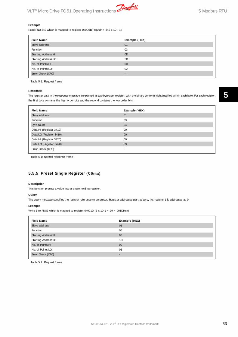
Example
Read PNU 342 which is mapped to register 0x0D5B(RegAdr = 342 x 10 - 1)
Field Name Example (HEX)
Slave address 01
Function 03
Starting Address HI 0D
Starting Address LO 5B
No. of Points HI 00
No. of Points LO 02
Error Check (CRC) -
Table 5.1: Request frame
Response
The register data in the response message are packed as two bytes per register, with the binary contents right justified within each byte. For each register,
the first byte contains the high order bits and the second contains the low order bits.
Field Name Example (HEX)
Slave address 01
Function 03
Byte count 04
Data HI (Register 3419) 00
Data LO (Register 3419) 00
Data HI (Register 3420) 00
Data LO (Register 3420) 03
Error Check (CRC) -
Table 5.1: Normal response frame
5.5.5 Preset Single Register (06HEX)
Description
This function presets a value into a single holding register.
Query
The query message specifies the register reference to be preset. Register addresses start at zero, i.e. register 1 is addressed as 0.
Example
Write 1 to PNU3 which is mapped to register 0x001D (3 x 10-1 = 29 = 001DHex)
Field Name Example (HEX)
Slave address 01
Function 06
Starting Address HI 00
Starting Address LO 1D
No. of Points HI 00
No. of Points LO 01
Error Check (CRC) -
Table 5.1: Request frame
VLT® Micro Drive FC 51 Operating Instructions 5 Modbus RTU
MG.02.A4.02 - VLT® is a registered Danfoss trademark 33
5

Response
The normal response is an echo of the query, returned after the register contents have been passed.
Field Name Example (HEX)
Slave address 01
Function 06
Starting Address HI 00
Starting Address LO 1D
No. of Points HI 00
No. of Points LO 01
Error Check (CRC) -
Table 5.1: Normal response frame
5.5.6 Preset Multiple Registers (10HEX)
Description
This function presets a value into a sequence of holding registers.
Query
The query message specifies the register references to be preset. Register addresses start at zero, i.e. register 1 is addressed as 0.
Example Write 65535 (655.35s) to PNU734 (4-bytes) mapped to 0 x 1CAB
Field Name Example (HEX)
Slave address 01
Function 10
Starting Address HI 1C
Starting Address LO AB
No. of Registers HI 00
No. of Registers LO 02
Byte count 04
Write Data HI (Register 7339) 00
Write Data LO (Register 7339) 00
Write Data HI (Register 7340) FF
Write Data LO (Register 7340) FF
Error Check (CRC) -
Table 5.1: Request frame
Response
The normal response returns the slave address, function code, starting address, and quantity of registers preset.
Field Name Example (HEX)
Slave address 01
Function 10
Starting Address HI 1C
Starting Address LO AB
No. of Registers HI 00
No. of Registers LO 02
Error Check (CRC) -
Table 5.1: Normal response frame
5 Modbus RTU VLT® Micro Drive FC 51 Operating Instructions
34 MG.02.A4.02 - VLT® is a registered Danfoss trademark
5

5.6 Danfoss FC Control Profile
5.6.1 Control Word According to FC Profile
Bit Bit value = 0 Bit value = 1
00 Preset reference select - lsb Preset reference select - lsb
01 Preset reference select - msb Preset reference select - msb
02 DC brake Ramp
03 Coasting No coasting
04 Quick stop Ramp
05 Freeze output No freeze output
06 Ramp stop Start
07 No function Reset
08 No function Jog
09 Ramp 1 Ramp 2
10 Data invalid Data valid
11 No function Relay 01 active
12 No function No function
13 Setup 1 Setup 2
14 No function No function
15 No function Reverse
5.6.2 Explanation of the Control Bits
Bits 00/01
Bits 00 and 01 are used to choose between the four reference values, which are pre-programmed in par. 3-10 Preset Reference according to the following
table:
Programmed ref. value Parameter Bit 01 Bit 02
1 3-10 [0] 0 0
2 3-10 [1] 0 1
3 3-10 [2] 1 0
4 3-10 [3] 1 1
NB!
In par. 8-56 Preset reference a selection is made to define how Bit 00/01 gates with the corresponding function on the digital inputs.
Bit 02, DC brake:
Bit 02 = “0” leads to DC braking and stop. Braking current and duration are set in par. 2-01 DC Brake current and 2-02 Braking time.
Bit 02 = “1” leads to ramping.
VLT® Micro Drive FC 51 Operating Instructions 5 Modbus RTU
MG.02.A4.02 - VLT® is a registered Danfoss trademark 35
5

Bit 03, Coasting:
Bit 03 = “0” shuts off the output transistors causing the motor to coast to a standstill.
Bit 03 = “1” enables the frequency converter to start the motor if the other starting conditions have been fulfilled.
NB!
In par. 8-50 Coasting select a selection is made to define how Bit 03 gates with the corresponding function on a digital input.
Bit 04, Quick stop:
Bit 04 = “0” causes a stop, in which the motor speed is ramped down to stop via 9ar. 3-81 Quick stop ramp time.
Bit 05, Hold output frequency:
Bit 05 = “0” causes the present output frequency (in Hz) to freeze. The frozen output frequency can then be changed only by means of the digital inputs
(par. 5-10 to 5-15) programmed to Speed up and Speed down.
NB!
If Freeze output is active, the frequency converter can only be stopped by the following:
• Bit 03 Coasting stop
• Bit 02 DC braking
• Digital input (par. 5-10 to 5-15) programmed to DC braking, Coasting stop or Reset and coasting stop.
Bit 06, Ramp stop/start:
Bit 06 = “0” causes a stop, in which the motor speed is ramped down to stop via the selected ramp down parameter.
Bit 06 = “1” permits the frequency converter to start the motor, if the other starting conditions have been fulfilled.
NB!
In par. 8-53 Start select a selection is made to define how Bit 06 Ramp stop/start gates with the corresponding function on a digital
input.
Bit 07, Reset:
Bit 07 = “0” does not cause a reset.
Bit 07 = “1” causes the reset of a trip. Reset is activated on the signal's leading edge, i.e. when changing from logic “0” to logic “1”.
Bit 08, Jog:
Bit 08 = “1” causes the output frequency to be determined by par. 3-19 Jog speed.
Bit 09, Selection of ramp 1/2:
Bit 09 = “0” means the ramp 1 is active (par. 3-40 to 3-47).
Bit 09 = ”1” means that ramp 2 (par. 3-50 to 3-57) is active.
Bit 10, Data not valid/Data valid:
Is used to tell the frequency converter whether the control word is to be used or ignored.
Bit 10 = “0” causes the control word to be ignored.
Bit 10 =”1” causes the control word to be used.
Bit 11, Relay 01:
Bit 11 = “0” Relay 01 not activated
Bit 11 = “1” Relay 01 is activated, provided Control word Bit 11 has been chosen in par. 5-40 Function relay.
5 Modbus RTU VLT® Micro Drive FC 51 Operating Instructions
36 MG.02.A4.02 - VLT® is a registered Danfoss trademark
5

Bit 12:
Not used.
Bit 13, Selection of set-up:
Bit 13 = is used to choose the active set-up. The function is only possible when Multi set-ups is selected in par. 0-10 Active Set-up.
NB!
In par. 8-55 Set-up select a selection is made to define how Bit 13 gates with the corresponding function on the digital inputs.
Bit 14:
Not used.
Bit 15, Reverse:
Bit 15 = “0” causes no reversing.
Bit 15 = “1” causes reversing.
NB!
Depends on par. 8-54 Reversing select.
5.6.3 Status Word According to FC Profile (STW)
Bit Bit value = 0 Bit value = 1
00 Control not ready Control ready
01 Unit not ready Unit ready
02 Coasting Enable
03 No error Error, trip
04 No error Error (no trip)
05 Reserved -
06 Not trip locked Trip locked
07 No warning Warning
08 Speed ≠ reference Speed = reference
09 Local operation Bus control
10 Out of frequency limit Frequency limit OK
11 Not running Running
12 No resistor brake fault Resistor brake fault
13 Voltage OK Voltage exceeded
14 Torque OK Torque exceeded
15 No thermal warning Thermal warning
VLT® Micro Drive FC 51 Operating Instructions 5 Modbus RTU
MG.02.A4.02 - VLT® is a registered Danfoss trademark 37
5

5.6.4 Explanation of the Status Bits
Bit 00, Control not ready/ready:
Bit 00 = “0” means that the frequency converter has tripped.
Bit 00 = “1” means that the frequency converter controls are ready, but that the power component is not necessarily receiving any power supply (in case
of external 24 V supply to controls).
Bit 01, Frequency converter ready:
Bit 01 = “1”. The frequency converter is ready for operation, but there is an active coasting command via the digital inputs or via serial communication.
Bit 02, Coasting stop:
Bit 02 = “0”. The frequency converter released the motor.
Bit 02 = “1”. The frequency converter can start the motor when a start command is given.
Bit 03, No error/trip:
Bit 03 = “0” means that the frequency converter is not in fault mode.
Bit 03 = “1” means that the frequency converter is tripped, and that a reset signal is required to re-establish operation.
Bit 04, No error/error (trip):
Bit 04 = “0” means that the frequency converter is not in fault mode.
Bit 04 = “1” means that there is a frequency converter error but no trip.
Bit 05:
Not used.
Bit 06, No error/trip lock:
Bit 06 = “0” means that the frequency converter is not in fault mode.
Bit 06 = “1” means that the frequency converter is tripped and locked.
Bit 07, No warning/warning:
Bit 07 = “0” means that there are no warnings.
Bit 07 = “1” means that a warning has occurred.
Bit 08, Speed ≠ reference/speed = reference:
Bit 08 = “0” means that the motor is running, but that the present speed is different from the preset speed reference. For example, this might occur
while the speed is being ramped up/down during start/stop.
Bit 08 = “1” means that the present motor speed matches the preset speed reference.
Bit 09, Local operation/bus control:
Bit 09 = “0” means that [Stop/Reset] is activated on the control unit. It is not possible to control the frequency converter via serial communication.
Bit 09 = “1” means that it is possible to control the frequency converter via serial communication.
Bit 10, Out of frequency limit:
Bit 10 = “0”, if the output frequency has reached the value in par. 4-12 Motor speed low limit or par . 4-13 Motor speed high limit.
Bit 10 = “1” means that the output frequency is within the defined limits.
Bit 11, Running:
Bit 11 = “0” means that the motor is not running.
Bit 11 = “1” means that the frequency converter has a start signal or that the output frequency is higher than 0 Hz.
Bit 12, Resistor brake fault:
Bit 12 = “0” means that there is no resistor brake fault.
Bit 12 = “1” means that there is a resistor brake fault.
5 Modbus RTU VLT® Micro Drive FC 51 Operating Instructions
38 MG.02.A4.02 - VLT® is a registered Danfoss trademark
5

Bit 13, Voltage OK/limit exceeded:
Bit 13 = “0” means that there are no voltage warnings.
Bit 13 = “1” means that the DC voltage in the frequency converter's intermediate circuit is too low or too high.
Bit 14, Torque OK/limit exceeded:
Bit 14 = “0” means that there are no current/torque warnings or errors.
Bit 14 = “1” means that there is a current/torque warning or error.
Bit 15, Thermal warning:
Bit 15 = “0” means that there is no thermal warning or error.
Bit 15 = “1” means that one of the thermal limits has been exceeded.
5.6.5 Bus Speed Reference Value
The speed reference value is transmitted to the frequency converter in a
relative value in %.
The value is transmitted in the form of a 16-bit word; in integers
(0-32767) the value 16384 (4000 Hex) corresponds to 100%. Negative
figures are formatted by means of 2's complement.
The Actual Output Frequency (MAV) is scaled in the same way as the bus
reference.
The reference and MAV are scaled as follows:
VLT® Micro Drive FC 51 Operating Instructions 5 Modbus RTU
MG.02.A4.02 - VLT® is a registered Danfoss trademark 39
5

6 Parameter Overview VLT® Micro Drive FC 51 Operating Instructions
40 MG.02.A4.02 - VLT® is a registered Danfoss trademark
6

6 Parameter OverviewP
aram
eter
Ove
rwie
v0-
** O
pera
tion
/Dis
play
0-0*
Bas
ic S
etti
ngs
0-03
Reg
ion
al S
etti
ngs
*[0]
Int
erna
tiona
l[1
] U
S0
-04
Ope
r. S
tate
at
Pow
er-u
p (H
and)
[0]
Resu
me
*[1]
For
ced
stop
, ref
= o
ld[2
] Fo
rced
sto
p, r
ef =
00-
1* S
et-u
p H
andl
ing
0-10
Act
ive
Set-
up
*[1]
Set
up 1
[2]
Setu
p 2
[9]
Mul
ti Se
tup
0-11
Edi
t Se
t-u
p*[
1] S
etup
1[2
] Se
tup
2[9
] Ac
tive
Setu
p0-
12 L
ink
Setu
ps[0
] N
ot L
inke
d*[
20]
Link
ed0-
31 C
ust
om R
eado
ut
Min
Sca
le0.
00 –
999
9.00
*0.0
00-
32 C
ust
om R
eado
ut
Max
Sca
le0.
00 –
999
9.00
*100
.00-
4* L
CP K
eypa
d0-
40 [
Han
d on
] K
ey o
n L
CP
[0]
Dis
able
d*[
1] E
nabl
ed0-
41 [
Off
/ R
eset
] K
ey o
n L
CP
[0]
Dis
able
All
*[1]
Ena
ble
All
[2]
Enab
le R
eset
Onl
y0
-42
[A
uto
on]
Key
on
LC
P[0
] D
isab
led
*[1]
Ena
bled
0-5*
Cop
y/Sa
ve0-
50 L
CP
Cop
y*[
0] N
o co
py[1
] Al
l to
LCP
[2]
All f
rom
LCP
[3]
Size
inde
p. f
rom
LCP
0-51
Set
-up
Cop
y*[
0] N
o co
py[1
] Co
py f
rom
set
up 1
[2]
Copy
fro
m s
etup
2[9
] Co
py f
rom
Fac
tory
set
up0-
6* P
assw
ord
0-60
(M
ain
) M
enu
Pas
swor
d0
- 99
9 *
01-
** L
oad/
Mot
or
1-0*
Gen
eral
Set
ting
s1
-00
Con
figu
rati
on M
ode
*[0]
Spe
ed o
pen
loop
[3]
Proc
ess
1-0
1 M
otor
Con
trol
Pri
nci
ple
[0]
U/f
*[1]
VVC
+1
-03
Tor
que
Ch
arac
teri
stic
s*[
0] C
onst
ant
torq
ue[2
] Au
tom
atic
Ene
rgy
Opt
im.
1-0
5 Lo
cal M
ode
Con
figu
rati
on[0
] Sp
eed
Ope
n Lo
op*[
2] A
s co
nfig
in p
aram
. 1-0
01-
2* M
otor
Dat
a1
-20
Mot
or P
ower
[kW
] [H
P]
[1]
0.09
kW
/0.1
2 H
P[2
] 0.
12 k
W/0
.16
HP
[3]
0.18
kW
/0.2
5 H
P[4
] 0.
25 k
W/0
.33
HP
[5]
0.37
kW
/0.5
0 H
P[6
] 0.
55 k
W/0
.75
HP
[7]
0.75
kW
/1.0
0 H
P[8
] 1.
10 k
W/1
.50
HP
[9]
1.50
kW
/2.0
0 H
P[1
0] 2
.20
kW/3
.00
HP
[11]
3.0
0 kW
/4.0
0 H
P[1
2] 3
.70
kW/5
.00
HP
[13]
4.0
0 kW
/5.4
0 H
P[1
4] 5
.50
kW/7
.50
HP
[15]
7.5
0 kW
/10.
00 H
P[1
6] 1
1.00
kW
/15.
00 H
P1
-22
Mot
or V
olta
ge50
- 9
99 V
* 2
30 -
400
V1
-23
Mot
or F
requ
ency
20 -
400
Hz
* 50
Hz
1-2
4 M
otor
Cu
rren
t0.
01 -
26.
00 A
* M
otor
type
dep
.1
-25
Mot
or N
omin
al S
peed
100
- 99
99 r
pm *
Mot
orty
pe d
ep.
1-2
9 A
uto
mat
ic M
otor
Tu
ning
(A
MT)
*[0]
Off
[2]
Enab
le A
MT
1-3*
Adv
. Mot
or D
ata
1-3
0 S
tato
r R
esis
tan
ce (
Rs)
[Ohm
] *
Dep
. on
mot
or d
ata
1-3
3 S
tato
r Le
akag
e R
eact
ance
(X
1)
[Ohm
] *
Dep
. on
mot
or d
ata
1-3
5 M
ain
Rea
ctan
ce (
Xh
)[O
hm]
* D
ep. o
n m
otor
dat
a1-
5* L
oad
Inde
p. S
etti
ng1
-50
Mot
or M
agn
etis
atio
n a
t 0
Spee
d0
- 30
0 %
* 1
00 %
1-5
2 M
in S
peed
Nor
m. M
agne
t. [
Hz]
0.0
- 10
.0 H
z *
0.0
Hz
1-5
5 U
/f C
har
acte
rist
ic -
U0
- 99
9.9
V1
-56
U/f
Ch
arac
teri
stic
- F
0 -
400
Hz
1-6*
Loa
d D
epen
. Set
ting
1-6
0 Lo
w S
peed
Loa
d C
ompe
nsat
ion
0 -
199
% *
100
%1
-61
Hig
h S
peed
Loa
d C
ompe
nsat
ion
0 -
199
% *
100
%1
-62
Slip
Com
pens
atio
n-4
00 -
399
% *
100
%1
-63
Slip
Com
pen
sati
on T
ime
Con
stan
t0.
05 -
5.0
0 s
* 0.
10 s
1-7*
Sta
rt A
djus
tmen
ts1
-71
Star
t D
elay
0.0
- 10
.0 s
* 0
.0 s
1-7
2 St
art
Fun
ctio
n[0
] D
C ho
ld /
del
ay t
ime
[1]
DC
brak
e /
dela
y tim
e*[
2] C
oast
/ d
elay
tim
e1
-73
Flyi
ng
Star
t*[
0] D
isab
led
[1]
Enab
led
1-8*
Sto
p A
djus
tmen
ts1
-80
Func
tion
at
Stop
*[0]
Coa
st[1
] D
C ho
ld1
-82
Min
Spe
ed f
or F
unct
. at
Stop
[H
z]0.
0 -
20.0
Hz
* 0.
0 H
z1-
9* M
otor
Tem
pera
ture
1-9
0 M
otor
Th
erm
al P
rote
ctio
n*[
0] N
o pr
otec
tion
[1]
Term
isto
r w
arni
ng[2
] Th
erm
isto
r tr
ip[3
] Et
r w
arni
ng[4
] Et
r tr
ip1
-93
The
rmis
tor
Res
ourc
e*[
0] N
one
[1]
Anal
og in
put
53[6
] D
igita
l inp
ut 2
92-
** B
rake
s2-
0* D
C-B
rake
2-0
0 D
C H
old
Cu
rren
t0
- 15
0 %
* 5
0 %
2-0
1 D
C B
rake
Cu
rren
t0
- 15
0 %
* 5
0 %
2-0
2 D
C B
raki
ng T
ime
0.0
- 60
.0 s
* 1
0.0
s2-
04
DC
Bra
ke C
ut
In S
peed
0.0
- 40
0.0
Hz
* 0.
0 H
z2-
1* B
rake
Ene
rgy
Func
t.2-
10
Bra
ke F
un
ctio
n*[
0] O
ff[1
] Re
sist
or b
rake
[2]
AC b
rake
2-1
1 B
rake
Res
isto
r (o
hm)
5 -
5000
* 5
2-1
6 A
C B
rake
, Max
cu
rren
t0
- 15
0 %
* 1
00 %
2-1
7 O
ver-
volt
age
Con
trol
*[0]
Dis
able
d[1
] En
able
d (n
ot a
t st
op)
[2]
Enab
led
2-2*
Mec
hani
cal B
rake
2-2
0 R
elea
se B
rake
Cu
rren
t0.
00 -
100
.0 A
* 0
.00
A2-
22
Act
ivat
e B
rake
Spe
ed [
Hz]
0.0
- 40
0.0
Hz
* 0.
0 H
z3-
** R
efer
ence
/ R
amps
3-0*
Ref
eren
ce L
imit
s3
-00
Ref
eren
ce R
ange
*[0]
Min
- M
ax[1
] -M
ax -
+M
ax3-
02
Min
imum
Ref
eren
ce-4
999
- 49
99 *
0.0
003-
03
Max
imu
m R
efer
ence
-499
9 -
4999
* 5
0.00
3-1*
Ref
eren
ces
3-1
0 P
rese
t R
efer
ence
-100
.0 -
100
.0 %
* 0
.00
%3-
11
Jog
Spee
d [H
z]0.
0 -
400.
0 H
z *
5.0
Hz
3-1
2 C
atch
up/
slow
Dow
n V
alue
0.00
- 1
00.0
% *
0.0
0 %
VLT® Micro Drive FC 51 Operating Instructions 6 Parameter Overview
MG.02.A4.02 - VLT® is a registered Danfoss trademark 41
6

3-14
Pre
set
Rel
ativ
e R
efer
ence
-100
.0 -
100
.0 %
* 0
.00
%3-
15 R
efer
ence
Res
ourc
e 1
[0]
No
func
tion
*[1]
Ana
log
Inpu
t 53
[2]
Anal
og in
put
60[8
] Pu
lse
inpu
t 33
[11]
Loc
al b
us r
ef[2
1] L
CP P
oten
tiom
eter
3-16
Ref
eren
ce R
esou
rce
2[0
] N
o fu
nctio
n[1
] An
alog
Inp
ut 5
3*[
2] A
nalo
g in
put
60[8
] Pu
lse
inpu
t 33
[11]
Loc
al b
us r
ef[2
1] L
CP P
oten
tiom
eter
3-17
Ref
eren
ce R
esou
rce
3[0
] N
o fu
nctio
n[1
] An
alog
Inp
ut 5
3[2
] An
alog
inpu
t 60
[8]
Puls
e in
put
33*[
11]
Loca
l bus
ref
[21]
LCP
Pot
entio
met
er3-
18 R
elat
ive
Scal
ing
Ref
. Res
ourc
e*[
0] N
o fu
nctio
n[1
] An
alog
Inp
ut 5
3[2
] An
alog
inpu
t 60
[8]
Puls
e in
put
33[1
1] L
ocal
bus
ref
[21]
LCP
Pot
entio
met
er3-
4* R
amp
13-
40 R
amp
1 T
ype
*[0]
Lin
ear
[2]
Sine
2 ra
mp
3-41
Ram
p 1
Ram
p u
p Ti
me
0.05
- 3
600
s *
3.00
s3-
42 R
amp
1 R
amp
Dow
n T
ime
0.05
- 3
600
s *
3.00
s3-
5* R
amp
23-
50 R
amp
2 T
ype
*[0]
Lin
ear
[2]
Sine
2 ra
mp
3-51
Ram
p 2
Ram
p u
p Ti
me
0.05
- 3
600
s *
3.00
s3-
52 R
amp
2 R
amp
dow
n T
ime
0.05
- 3
600
s *
3.00
s3-
8* O
ther
Ram
ps
3-8
0 Jo
g R
amp
Tim
e0.
05 -
360
0 s
* 3.
00 s
3-8
1 Q
uic
k St
op R
amp
Tim
e0.
05 -
360
0 s
* 3.
00 s
4-**
Lim
its
/ W
arni
ngs
4-1*
Mot
or L
imit
s4
-10
Mot
or S
peed
Dir
ecti
on[0
] Cl
ockw
ise
[1]
Coun
terC
lock
wis
e*[
2] B
oth
4-1
2 M
otor
Spe
ed L
ow L
imit
[H
z]0.
0 -
400.
0 H
z *
0.0
Hz
4-1
4 M
otor
Spe
ed H
igh
Lim
it [
Hz]
0.1
- 40
0.0
Hz
* 65
.0 H
z4
-16
Torq
ue
Lim
it M
otor
Mod
e0
- 40
0 %
* 1
50 %
4-1
7 To
rqu
e Li
mit
Gen
erat
or M
ode
0 -
400
% *
100
%4-
5* A
dj. W
arni
ngs
4-5
0 W
arn
ing
Cu
rren
t Lo
w0.
00 -
26.
00 A
* 0
.00
A4
-51
War
nin
g C
urr
ent
Hig
h0.
00 -
26.
00 A
* 2
6.00
A4
-58
Mis
sin
g M
otor
Ph
ase
Fun
ctio
n[0
] O
ff*[
1] O
n4-
6* S
peed
Byp
ass
4-6
1 B
ypas
s Sp
eed
From
[H
z]0.
0 -
400.
0 H
z *
0.0
Hz
4-6
3 B
ypas
s Sp
eed
To [
Hz]
0.0
- 40
0.0
Hz
* 0.
0 H
z5-
1* D
igit
al I
nput
s5
-10
Term
inal
18
Dig
ital
In
put
[0]
No
func
tion
[1]
Res
et[2
] Co
ast
inve
rse
[3]
Coas
t an
d re
set
inv.
[4]
Qui
ck s
top
inve
rse
[5]
DC-
brak
e in
v.[6
] St
op in
v*[
8] S
tart
[9]
Latc
hed
star
t[1
0] R
ever
sing
[11]
Sta
rt r
ever
sing
[12]
Ena
ble
star
t fo
rwar
d[1
3] E
nabl
e st
art
reve
rse
[14]
Jog
[16-
18]
Pres
et r
ef b
it 0-
2[1
9] F
reez
e re
fere
nce
[20]
Fre
eze
outp
ut[2
1] S
peed
up
[22]
Spe
ed d
own
[23]
Set
up s
elec
t bi
t 0
[28]
Cat
ch u
p[2
9] S
low
dow
n[3
4] R
amp
bit
0[6
0] C
ount
er A
(up
)[6
1] C
ount
er A
(do
wn)
[62]
Res
et c
ount
er A
[63]
Cou
nter
B (
up)
[64]
Cou
nter
B (
dow
n)[6
5] R
eset
Coun
ter
B5-
11
Term
inal
19
Dig
ital
In
put
See
par.
5-1
0. *
[10
] Re
vers
ing
5-1
2 Te
rmin
al 2
7 D
igit
al I
npu
tSe
e pa
r. 5
-10.
* [
1] R
eset
5-1
3 Te
rmin
al 2
9 D
igit
al I
npu
tSe
e pa
r. 5
-10.
* [
14]
Jog
5-1
5 Te
rmin
al 3
3 D
igit
al I
npu
tSe
e pa
r. 5
-10.
* [
16]
Pres
et r
ef b
it 0
[26]
Pre
cise
Sto
p In
vers
e[2
7] S
tart
, Pre
cise
Sto
p[3
2] P
ulse
Inp
ut5-
4* R
elay
s5-
40
Fun
ctio
n R
elay
*[0]
No
opre
atio
n[1
] Co
ntro
l rea
dy[2
] D
rive
read
y[3
] D
rive
read
y, R
emot
e[4
] En
able
/ N
o w
arni
ng[5
] D
rive
runn
ing
[6]
Runn
ing
/ N
o w
arni
ng[7
] Ru
n in
ran
ge /
No
war
ning
[8]
Run
on r
ef /
No
war
ning
[9]
Alar
m[1
0] A
larm
or
war
ning
[12]
Out
of
curr
ent
rang
e[1
3] B
elow
cur
rent
, low
[14]
Abo
ve c
urre
nt, h
igh
[21]
The
rmal
war
ning
[22]
Rea
dy, N
o th
erm
al w
arni
ng[2
3] R
emot
e re
ady,
No
ther
mal
war
ning
[24]
Rea
dy, V
olta
ge o
k
[25]
Rev
erse
[26]
Bus
ok
[28]
Bra
ke,N
oWar
n[2
9] B
rake
rea
dy/N
oFau
lt[3
0] B
rake
Faul
t (I
GBT
)[3
2] M
ech.
brak
e co
ntro
l[3
6] C
ontr
ol w
ord
bit
11[5
1] L
ocal
ref
. act
ive
[52]
Rem
ote
ref.
activ
e[5
3] N
o al
arm
[54]
Sta
rt c
md
activ
e[5
5] R
unni
ng r
ever
se[5
6] D
rive
in h
and
mod
e[5
7] D
rive
in a
uto
mod
e[6
0-63
] Co
mpa
rato
r 0-
3[7
0-73
] Lo
gic
rule
0-3
[81]
SL
digi
tal o
utpu
t B
5-5*
Pul
se I
nput
5-5
5 Te
rmin
al 3
3 Lo
w F
requ
ency
20 -
499
9 H
z *
20 H
z5
-56
Term
inal
33
Hig
h F
requ
ency
21 -
500
0 H
z *
5000
Hz
5-5
7 Te
rm. 3
3 Lo
w R
ef./
Feed
b. V
alu
e-4
999
- 49
99 *
0.0
005
-58
Term
. 33
Hig
h R
ef./
Feed
b. V
alue
-499
9 -
4999
* 5
0.00
06-
** A
nalo
g In
/Out
6-0*
Ana
log
I/O
Mod
e6
-00
Live
Zer
o Ti
meo
ut
Tim
e1
- 99
s *
10
s6
-01
Live
Zer
o Ti
meo
utF
un
ctio
n*[
0] O
ff[1
] Fr
eeze
out
put
[2]
Stop
[3]
Jogg
ing
[4]
Max
spe
ed[5
] St
op a
nd t
rip6-
1* A
nalo
g In
put
16
-10
Term
inal
53
Low
Vol
tage
0.00
- 9
.99
V *
0.07
V6
-11
Term
inal
53
Hig
h V
olta
ge0.
01 -
10.
00 V
* 1
0.00
V6
-12
Term
inal
53
Low
Cu
rren
t0.
00 -
19.
99 m
A *
0.14
mA
6 Parameter Overview VLT® Micro Drive FC 51 Operating Instructions
42 MG.02.A4.02 - VLT® is a registered Danfoss trademark
6

6-13
Ter
min
al 5
3 H
igh
Cu
rren
t0.
01 -
20.
00 m
A *
20.0
0 m
A6-
14 T
erm
. 53
Low
Ref
./Fe
edb.
Val
ue
-499
9 -
4999
* 0
.000
6-15
Ter
m. 5
3 H
igh
Ref
./Fe
edb.
Val
ue
-499
9 -
4999
* 5
0.00
06-
16 T
erm
inal
53
Filt
er T
ime
Con
stan
t0.
01 -
10.
00 s
* 0
.01
s6-
19 T
erm
inal
53
mod
e*[
0] V
olta
ge m
ode
[1]
Curr
ent
mod
e6-
2* A
nalo
g In
put
26-
22 T
erm
inal
60
Low
Cu
rren
t0.
00 -
19.
99 m
A *
0.14
mA
6-23
Ter
min
al 6
0 H
igh
Cu
rren
t0.
01 -
20.
00 m
A *
20.0
0 m
A6-
24 T
erm
. 60
Low
Ref
./Fe
edb.
Val
ue
-499
9 -
4999
* 0
.000
6-25
Ter
m. 6
0 H
igh
Ref
./Fe
edb.
Val
ue
-499
9 -
4999
* 5
0.00
6-26
Ter
min
al 6
0 Fi
lter
Tim
e C
onst
ant
0.01
- 1
0.00
s *
0.0
1 s
6-8*
LCP
pot
enti
omet
er6-
81 L
CP
pot
m. L
ow R
efer
ence
-499
9 -
4999
* 0
.000
6-82
LC
P p
otm
. Hig
h R
efer
ence
-499
9 -
4999
* 5
0.00
6-9*
Ana
log
Out
put
xx6-
90 T
erm
inal
42
Mod
e*[
0] 0
-20
mA
[1]
4-20
mA
[2]
Dig
ital O
utpu
t6-
91 T
erm
inal
42
An
alog
Ou
tpu
t*[
0] N
o op
erat
ion
[10]
Out
put
Freq
uenc
y[1
1] R
efer
ence
[12]
Fee
dbac
k[1
3] M
otor
Cur
rent
[16]
Pow
er[2
0] B
usCo
ntro
l6-
92 T
erm
inal
42
Dig
ital
Ou
tpu
tSe
e pa
r. 5
-40
* [0
] N
o O
pera
tion
[80]
SL
Dig
ital O
utpu
t A
6-93
Ter
min
al 4
2 O
utp
ut
Min
Sca
le0.
00 -
200
.0 %
* 0
.00
%6-
94 T
erm
inal
42
Ou
tpu
t M
ax S
cale
0.00
- 2
00.0
% *
100
.0 %
7-**
Con
trol
lers
7-2*
Pro
cess
Ctr
l. Fe
edb
7-20
Pro
cess
CL
Feed
back
1 R
esou
rce
*[0]
NoF
unct
ion
[1]
Anal
og I
nput
53
[2]
Anal
og in
put
60[8
] Pu
lseI
nput
33[1
1] L
ocal
BusR
ef7-
3* P
roce
ss P
IC
trl.
7-30
Pro
cess
PI
Nor
mal
/ In
vers
e C
trl
*[0]
Nor
mal
[1]
Inve
rse
7-31
Pro
cess
PI
An
ti W
indu
p[0
] D
isab
le*[
1] E
nabl
e7-
32 P
roce
ss P
I St
art
Spee
d0.
0 -
200.
0 H
z *
0.0
Hz
7-33
Pro
cess
PI
Pro
port
ion
al G
ain
0.00
- 1
0.00
* 0
.01
7-34
Pro
cess
PI
Inte
gral
Tim
e0.
10 -
999
9 s
* 99
99 s
7-38
Pro
cess
PI
Feed
For
war
d Fa
ctor
0 -
400
% *
0 %
7-39
On
Ref
eren
ce B
andw
idth
0 -
200
% *
5 %
8-**
Com
m. a
nd O
ptio
ns8-
0* G
ener
al S
etti
ngs
8-01
Con
trol
Sit
e*[
0] D
igita
l and
Con
trol
Wor
d[1
] D
igita
l onl
y[2
] Co
ntro
lWor
d on
ly8-
02 C
ontr
ol W
ord
Sou
rce
[0]
Non
e*[
1] F
C RS
485
8-03
Con
trol
Wor
d Ti
meo
ut
Tim
e0.
1 -
6500
s *
1.0
s8-
04 C
ontr
ol W
ord
Tim
eou
t Fu
nct
ion
*[0]
Off
[1]
Free
ze O
utpu
t[2
] St
op[3
] Jo
ggin
g
[4]
Max
. Spe
ed[5
] St
op a
nd t
rip8-
06 R
eset
Con
trol
Wor
d Ti
meo
ut
*[0]
No
Func
tion
[1]
Do
rese
t8-
3* F
C Po
rt S
etti
ngs
8-30
Pro
toco
l*[
0] F
C[2
] M
odbu
s8-
31 A
ddre
ss1
- 24
7 *
18-
32 F
C P
ort
Bau
d R
ate
[0]
2400
Bau
d[1
] 48
00 B
aud
*[2]
960
0 Ba
ud[3
] 19
200
Baud
*[4]
384
00 B
aud
8-33
FC
Por
t P
arit
y*[
0] E
ven
Parit
y, 1
Sto
p Bi
t[1
] O
dd P
arity
, 1 S
top
Bit
[2]
No
Parit
y, 1
Sto
p Bi
t[3
] N
o Pa
rity,
2 S
top
Bits
8-35
Min
imu
m R
espo
nse
Del
ay0.
001-
0.5
* 0.
010
s8-
36 M
ax R
espo
nse
Del
ay0.
100
- 10
.00
s *
5.00
0 s
8-5*
Dig
ital
/Bus
8-50
Coa
stin
g Se
lect
[0]
Dig
italIn
put
[1]
Bus
[2]
Logi
cAnd
*[3]
Log
icO
r8-
51 Q
uic
k St
op S
elec
tSe
e pa
r. 8
-50
* [3
] Lo
gicO
r8-
52 D
C B
rake
Sel
ect
See
par.
8-5
0 *
[3]
Logi
cOr
8-53
Sta
rt S
elec
tSe
e pa
r. 8
-50
* [3
] Lo
gicO
r8-
54 R
ever
sin
g Se
lect
See
par.
8-5
0 *
[3]
Logi
cOr
8-55
Set
-up
Sele
ctSe
e pa
r. 8
-50
* [3
] Lo
gicO
r8-
56 P
rese
t R
efer
ence
Sel
ect
See
par.
8-5
0 *
[3]
Logi
cOr
8-9*
Bus
Jog
/ F
eedb
ack
8-9
4 B
us
feed
back
10x
8000
- 0
x7FF
F *
013
-**
Smar
t Lo
gic
13-0
* SL
C Se
ttin
gs1
3-0
0 S
L C
ontr
olle
r M
ode
*[0]
Off
[1]
On
13-
01 S
tart
Eve
nt
[0]
Fals
e[1
] Tr
ue[2
] Ru
nnin
g[3
] In
Rang
e[4
] O
nRef
eren
ce[7
] O
utO
fCur
rent
Ran
ge[8
] Be
low
ILow
[9]
Abov
eIH
igh
[16]
The
rmal
War
ning
[17]
Mai
nOut
OfR
ange
[18]
Rev
ersi
ng[1
9] W
arni
ng[2
0] A
larm
_Trip
[21]
Ala
rm_T
ripLo
ck[2
2-25
] Co
mpa
rato
r 0-
3[2
6-29
] Lo
gicR
ule0
-3[3
3] D
igita
lInpu
t_18
[34]
Dig
italIn
put_
19[3
5] D
igita
lInpu
t_27
[36]
Dig
italIn
put_
29[3
8] D
igita
lInpu
t_33
*[39
] St
artC
omm
and
[40]
Driv
eSto
pped
13-
02 S
top
Even
tSe
e pa
r. 1
3-01
* [
40]
Driv
eSto
pped
13-
03 R
eset
SLC
*[0]
Do
not
rese
t[1
] Res
et S
LC13
-1*
Com
para
tors
VLT® Micro Drive FC 51 Operating Instructions 6 Parameter Overview
MG.02.A4.02 - VLT® is a registered Danfoss trademark 43
6

13
-10
Com
para
tor
Ope
ran
d*[
0] D
isab
led
[1]
Ref
eren
ce[2
] Fe
edba
ck[3
] M
otor
Spee
d[4
] M
otor
Curr
ent
[6]
Mot
orPo
wer
[7]
Mot
orVo
ltage
[8]
DCL
inkV
olta
ge[1
2] A
nalo
gInp
ut53
[13]
Ana
logI
nput
60[1
8] P
ulse
Inpu
t33
[20]
Ala
rmN
umbe
r[3
0] C
ount
erA
[31]
Cou
nter
B1
3-1
1 C
ompa
rato
r O
pera
tor
[0]
Less
Tha
n*[
1] A
ppro
xim
atel
y eq
uals
[2]
Gre
ater
Tha
n1
3-1
2 C
ompa
rato
r V
alu
e-9
999
- 99
99 *
0.0
13-2
* Ti
mer
s13
-20
SL C
ontr
olle
r Ti
mer
0.0
- 36
00 s
* 0
.0 s
13-4
* Lo
gic
Rul
es1
3-4
0 Lo
gic
Ru
le B
oole
an 1
See
par.
13-
01 *
[0]
Fal
se[3
0] -
[32
] SL
Tim
e-ou
t 0-
21
3-4
1 L
ogic
Ru
le O
pera
tor
1*[
0] D
isab
led
[1]
And
[2]
Or
[3]
And
not
[4]
Or
not
[5]
Not
and
[6]
Not
or
[7]
Not
and
not
[8]
Not
or
not
13
-42
Logi
c R
ule
Boo
lean
2Se
e pa
r. 1
3-40
13
-43
Log
ic R
ule
Ope
rato
r 2
See
par.
13-
41 *
[0]
Dis
able
d1
3-4
4 Lo
gic
Ru
le B
oole
an 3
See
par.
13-
4013
-5*
Stat
es1
3-5
1 SL
Con
trol
ler
Even
tSe
e pa
r. 1
3-40
13
-52
SL
Con
trol
ler
Act
ion
*[0]
Dis
able
d
[1]
NoA
ctio
n[2
] Se
lect
Setu
p1[3
] Se
lect
Setu
p2[1
0-17
] Se
lect
Pres
etRe
f0-7
[18]
Sel
ectR
amp1
[19]
Sel
ectR
amp2
[22]
Run
[23]
Run
Rev
erse
[24]
Sto
p[2
5] Q
stop
[26]
DCs
top
[27]
Coa
st[2
8] F
reez
eOut
put
[29]
Sta
rtTi
mer
0[3
0] S
tart
Tim
er1
[31]
Sta
rtTi
mer
2[3
2] S
et D
igita
l Out
put
A Lo
w[3
3] S
et D
igita
l Out
put
B Lo
w[3
8] S
et D
igita
l Out
put
A H
igh
[39]
Set
Dig
ital O
utpu
t B
Hig
h[6
0] R
eset
Coun
terA
[61]
Res
etCo
unte
rB14
-**
Spec
ial F
unct
ions
14-0
* In
vert
er S
wit
chin
g1
4-01
Sw
itch
ing
Freq
uen
cy[0
] 2
kHz
*[1]
4 k
Hz
[2]
8 kH
z[4
] 16
kH
z1
4-03
Ove
rmod
ulat
ion
[0]
Off
*[1]
On
14-1
* M
ains
mon
itor
ing
14-
12
Fu
nct
ion
at
mai
ns im
bala
nce
*[0]
Trip
[1]
War
ning
[2]
Dis
able
d14
-2*
Trip
Res
et1
4-20
Res
et M
ode
*[0]
Man
ual r
eset
[1-9
] Au
toRe
set
1-9
[10]
Aut
oRes
et 1
0[1
1] A
utoR
eset
15
[12]
Aut
oRes
et 2
0[1
3] I
nfin
ite a
uto
rese
t1
4-21
Au
tom
atic
Res
tart
Tim
e0
- 60
0 s
* 10
s
14-
22 O
pera
tion
Mod
e*[
0] N
orm
al O
pera
tion
[2]
Initi
alis
atio
n1
4-2
6 A
ctio
n A
t In
vert
er F
ault
*[0]
Trip
[1]
War
ning
14-4
* En
ergy
Opt
imis
ing
14-
41 A
EO M
inim
um
Mag
net
isat
ion
40 -
75
% *
66
%15
-**
Dri
ve I
nfor
mat
ion
15-0
* O
pera
ting
Dat
a1
5-00
Ope
rati
ng D
ays
15-
01 R
un
ning
Hou
rs1
5-02
kW
h C
oun
ter
15-
03 P
ower
Ups
15-
04 O
ver
Tem
ps1
5-05
Ove
r V
olts
15-
06 R
eset
kW
h C
oun
ter
*[0]
Do
not
rese
t[1
] Res
et c
ount
er1
5-07
Res
et R
un
ning
Hou
rs C
oun
ter
*[0]
Do
not
rese
t[1
] Res
et c
ount
er15
-3*
Faul
t Lo
g1
5-30
Fau
lt L
og:
Erro
r C
ode
15-4
* D
rive
Ide
ntif
icat
ion
15-
40 F
C T
ype
15-
41 P
ower
Sec
tion
15-
42 V
olta
ge1
5-43
Sof
twar
e V
ersi
on1
5-46
Fre
quen
cy C
onve
rter
Ord
er. N
o1
5-48
LC
P I
d N
o1
5-51
Fre
quen
cy C
onve
rter
Ser
ial N
o16
-**
Dat
a R
eado
uts
16-0
* G
ener
al S
tatu
s1
6-00
Con
trol
Wor
d0
- 0X
FFFF
16-
01 R
efer
ence
[U
nit]
-499
9 -
4999
16-
02 R
efer
ence
%-2
00.0
- 2
00.0
%1
6-03
Sta
tus
Wor
d0
- 0X
FFFF
16-
05 M
ain
Act
ual V
alu
e [%
]-2
00.0
- 2
00.0
%1
6-0
9 C
usto
m R
eado
utD
ep. o
n pa
r. 0
-31,
0-3
2 an
d 4-
14
16-1
* M
otor
Sta
tus
16-1
0 P
ower
[kW
]16
-11
Pow
er [
hp]
16-1
2 M
otor
Vol
tage
[V
]16
-13
Freq
uen
cy [
Hz]
16-1
4 M
otor
Cu
rren
t [A
]16
-15
Freq
uen
cy [
%]
16-1
8 M
otor
Th
erm
al [
%]
16-3
* D
rive
Sta
tus
16-3
0 D
C L
ink
Vol
tage
16-3
4 H
eats
ink
Tem
p.16
-35
Inve
rter
Th
erm
al16
-36
Inv.
Nom
. Cu
rren
t16
-37
Inv.
Max
. Cu
rren
t16
-38
SL C
ontr
olle
r St
ate
16-5
* R
ef. /
Fee
db.
16-5
0 Ex
tern
al R
efer
ence
16-5
1 P
uls
e R
efer
ence
16-5
2 Fe
edba
ck [
Un
it]
16-6
* In
puts
/ O
utpu
ts16
-60
Dig
ital
In
put
18,1
9,27
,33
0 -
1111
16-6
1 D
igit
al I
npu
t 29
0 -
116
-62
An
alog
In
put
53 (
volt
)16
-63
An
alog
In
put
53 (
curr
ent)
16-6
4 A
nal
og I
npu
t 60
16-6
5 A
nal
og O
utp
ut
42 [
mA
]16
-68
Pu
lse
Inpu
t [H
z]16
-71
Rel
ay O
utp
ut
[bin
]16
-72
Cou
nte
r A
16-7
3 C
oun
ter
B16
-8*
Fiel
dbus
/ F
C Po
rt16
-86
FC P
ort
REF
10x
8000
- 0
x7FF
FF16
-9*
Dia
gnos
is R
eado
uts
16-9
0 A
larm
Wor
d0
- 0X
FFFF
FFFF
16-9
2 W
arn
ing
Wor
d0
- 0X
FFFF
FFFF
16-9
4 Ex
t. S
tatu
s W
ord
0 -
0XFF
FFFF
FF
6 Parameter Overview VLT® Micro Drive FC 51 Operating Instructions
44 MG.02.A4.02 - VLT® is a registered Danfoss trademark
6

6.2.1 Conversion Index
The various attributes of each parameter are displayed in the section Factory Settings. Parameter values are transferred as whole numbers only. Con-
version factors are therefore used to transfer decimals according to the table below.
Example:
Par. 1-24 Motor Current has a conversion index of -2 (i.e. conversion factor of 0.01 according to the table below). To set the parameter to 2.25 A, transfer
the value 225 via Modbus. The Conversion Factor of 0.01 means that the value transferred is multiplied by 0.01 in the drive. The vale 225 transferred on
the bus is thus perceived as 2.25 A in the drive.
Conversion index Conversion factor
2 10
1 100
0 1
-1 0.1
-2 0.01
-3 0.001
-4 0.0001
-5 0.00001
Table 6.1: Conversion table
6.2.2 Change during operation
“TRUE” means that the parameter can be changed while the frequency converter is in operation and “FALSE” means that the frequency converter must
be stopped before a change can be made.
6.2.3 2-Set-up
“All set-up”: The parameter can be set individually in each of the two set-ups, i.e. one single parameter can have two different data values.
”1 set-up”: Data value will be the same in both set-ups.
6.2.4 Type
Data Type Description Type
2 Integer 8 Int8
3 Integer 16 Int16
4 Integer 32 Int32
5 Unsigned 8 Uint8
6 Unsigned 16 Uint16
7 Unsigned 32 Uint32
9 Visible string VisibleString
VLT® Micro Drive FC 51 Operating Instructions 6 Parameter Overview
MG.02.A4.02 - VLT® is a registered Danfoss trademark 45
6

Par
amet
er N
um
ber
Par
amet
er D
escr
ipti
onD
efau
lt V
alue
2 S
etu
pC
han
ge D
uri
ng O
pera
tion
Con
vers
ion
Ind
exTy
pe0
- 03
Regi
onal
Set
tings
[0]
Inte
rnat
iona
l1
set-
upFA
LSE
-U
int8
0 -
04O
pera
ting
Stat
e at
Pow
er-u
p (H
and)
[1]
Forc
ed s
top
ref=
old
All s
et-u
psTR
UE
-U
int8
0 -
10Ac
tive
Set-
up[1
] Se
t-up
11
set-
upTR
UE
-U
int8
0 -
11Ed
it Se
t-up
[1]
Set-
up 1
1 se
t-up
TRU
E-
Uin
t80
- 12
Link
Set
ups
[20]
Lin
ked
All s
et-u
psFA
LSE
-U
int8
0 -
40[H
and
on]
Key
on L
CP[1
] En
able
dAl
l set
-ups
TRU
E-
Uin
t80
- 41
[Off
/ R
eset
] Ke
y on
LCP
[1]
Enab
le A
llAl
l set
-ups
TRU
E-
Uin
t80
- 42
[Aut
o on
] Ke
y on
LCP
[1]
Enab
led
All s
et-u
psTR
UE
-U
int8
0 -
50LC
P Co
py[0
] N
o co
py1
set-
upFA
LSE
-U
int8
0 -
51Se
t-up
Cop
y[0
] N
o co
py1
set-
upFA
LSE
-U
int8
0 -
60M
ain
Men
u Pa
ssw
ord
01
set-
upTR
UE
0U
int1
6
6.2.
50
-**
Ope
rati
on/D
ispl
ay
6 Parameter Overview VLT® Micro Drive FC 51 Operating Instructions
46 MG.02.A4.02 - VLT® is a registered Danfoss trademark
6

Par
amet
er N
um
ber
Par
amet
er D
escr
ipti
onD
efau
lt V
alue
2 S
etu
pC
han
ge D
uri
ng O
pera
tion
Con
vers
ion
Ind
exTy
pe1
- 00
Conf
igur
atio
n M
ode
[0]
Spee
d op
en lo
opAl
l set
-ups
TRU
E-
Uin
t81
- 01
Mot
or C
ontr
ol P
rinci
ple
[1]
VVC+
All s
et-u
psFA
LSE
-U
int8
1 -
03To
rque
Cha
ract
eris
tics
[0]
Cons
tant
tor
que
All s
et-u
psTR
UE
-U
int8
1 -
05H
and
Mod
e Co
nfig
urat
ion
[2]
As m
ode
par
1-00
All s
et-u
psTR
UE
-U
int8
1 -
20M
otor
Pow
er
All s
et-u
psFA
LSE
-U
int8
1 -
22M
otor
Vol
tage
Al
l set
-ups
FALS
E0
Uin
t16
1 -
23M
otor
Fre
quen
cy
All s
et-u
psFA
LSE
0U
int1
61
- 24
Mot
or C
urre
nt
All s
et-u
psFA
LSE
-2U
int1
61
- 25
Mot
or N
omin
al S
peed
Al
l set
-ups
FALS
E0
Uin
t16
1 -
29Au
tom
atic
Mot
or T
unin
g (A
MT)
[0]
Off
1 se
t-up
FALS
E-
Uin
t81
- 30
Stat
or R
esis
tanc
e (R
s)
All s
et-u
psFA
LSE
-2U
int1
61
- 33
Stat
or L
eaka
ge R
eact
ance
(X1
)
All s
et-u
psFA
LSE
-2U
int3
21
- 35
Mai
n Re
acta
nce
(Xh)
Al
l set
-ups
FALS
E-2
Uin
t32
1 -
50M
otor
Mag
netis
atio
n at
Zer
o Sp
eed
100%
All s
et-u
psTR
UE
0U
int1
61
- 52
Min
Spe
ed N
orm
al M
agne
tisin
g [H
z]0
Hz
All s
et-u
psTR
UE
-1U
int1
61
- 55
U/f
Cha
ract
eris
tic -
U
All s
et-u
psTR
UE
0U
int1
61
- 56
U/f
Cha
ract
eris
tic -
F
All s
et-u
psTR
UE
0U
int1
61
- 60
Low
Spe
ed L
oad
Com
pens
atio
n10
0%Al
l set
-ups
TRU
E0
Uin
t16
1 -
61H
igh
Spee
d Lo
ad C
ompe
nsat
ion
100%
All s
et-u
psTR
UE
0U
int1
61
- 62
Slip
Com
pens
atio
n10
0%Al
l set
-ups
TRU
E0
Int1
61
- 63
Slip
Com
pens
atio
n Ti
me
Cons
tant
0.1
sAl
l set
-ups
TRU
E-2
Uin
t16
1 -
71St
art
Del
ay0
sAl
l set
-ups
TRU
E-1
Uin
t81
- 72
Star
t Fu
nctio
n[2
] Co
ast/
dela
y tim
eAl
l set
-ups
TRU
E-
Uin
t81
- 73
Flyi
ng S
tart
[0]
Dis
able
dAl
l set
-ups
FALS
E-
Uin
t81
- 80
Func
tion
at S
top
[0]
Coas
tAl
l set
-ups
TRU
E-
Uin
t81
- 82
Min
Spe
ed f
or F
unct
ion
at S
top
[Hz]
0 H
zAl
l set
-ups
TRU
E-1
Uin
t16
1 -
90M
otor
The
rmal
Pro
tect
ion
[0]
No
prot
ectio
nAl
l set
-ups
TRU
E-
Uin
t81
- 93
Ther
mis
tor
Res
ourc
e[0
] N
one
All s
et-u
psFA
LSE
-U
int8
6.2.
61
-**
Load
/Mot
or
VLT® Micro Drive FC 51 Operating Instructions 6 Parameter Overview
MG.02.A4.02 - VLT® is a registered Danfoss trademark 47
6

Par
amet
er N
um
ber
Par
amet
er D
escr
ipti
onD
efau
lt V
alue
2 S
etu
pC
han
ge D
uri
ng O
pera
tion
Con
vers
ion
Ind
exTy
pe2
- 00
DC
Hol
d Cu
rren
t50
%Al
l set
-ups
TRU
E0
Uin
t16
2 -
01D
C Br
ake
Curr
ent
50%
All s
et-u
psTR
UE
0U
int1
62
- 02
DC
Brak
ing
Tim
e10
sAl
l set
-ups
TRU
E-1
Uin
t16
2 -
04D
C Br
ake
Cut
In S
peed
0 H
zAl
l set
-ups
TRU
E-1
Uin
t16
2 -
10Br
ake
Func
tion
[0]
Off
All s
et-u
psTR
UE
-U
int8
2 -
11Br
ake
Resi
stor
(oh
m)
All s
et-u
psTR
UE
0U
int1
62
- 16
AC B
rake
, Max
cur
rent
100%
All s
et-u
psTR
UE
0U
int1
62
- 17
Ove
r-vo
ltage
Con
trol
[0]
Dis
able
dAl
l set
-ups
TRU
E-
Uin
t82
- 20
Rele
ase
Brak
e Cu
rren
t0
AAl
l set
-ups
TRU
E-2
Uin
t32
2 -
22Ac
tivat
e Br
ake
Spee
d [H
z]0
Hz
All s
et-u
psTR
UE
-1U
int1
6
6.2.
72
-**
Bra
kes
6 Parameter Overview VLT® Micro Drive FC 51 Operating Instructions
48 MG.02.A4.02 - VLT® is a registered Danfoss trademark
6

Par
amet
er N
um
ber
Par
amet
er D
escr
ipti
onD
efau
lt V
alue
2 S
etu
pC
han
ge D
uri
ng O
pera
tion
Con
vers
ion
Ind
exTy
pe3
- 00
Refe
renc
e Ra
nge
[0]
Min
- M
axAl
l set
-ups
TRU
E-
Uin
t83
- 02
Min
imum
Ref
eren
ce0
All s
et-u
psTR
UE
-3In
t32
3 -
03M
axim
um R
efer
ence
50Al
l set
-ups
TRU
E-3
Int3
23
- 10
Pres
et R
efer
ence
0%Al
l set
-ups
TRU
E-2
Int1
63
- 11
Jog
Spee
d [H
z]5
Hz
All s
et-u
psTR
UE
-1U
int1
63
- 12
Catc
h up
/slo
w D
own
Valu
e0%
All s
et-u
psTR
UE
-2In
t16
3 -
14Pr
eset
Rel
ativ
e Re
fere
nce
0%Al
l set
-ups
TRU
E-2
Int1
63
- 15
Ref
eren
ce R
esou
rce
1[1
] An
alog
in 5
3Al
l set
-ups
TRU
E-
Uin
t83
- 16
Refe
renc
e Re
sour
ce 2
[2]
Anal
og in
60
All s
et-u
psTR
UE
-U
int8
3 -
17Re
fere
nce
Reso
urce
3[1
1] L
ocal
bus
ref
eren
ceAl
l set
-ups
TRU
E-
Uin
t83
- 18
Rela
tive
Scal
ing
Refe
renc
e Re
sour
ce[0
] N
o fu
nctio
nAl
l set
-ups
TRU
E-
Uin
t83
- 40
Ram
p 1
Type
[0]
Line
arAl
l set
-ups
TRU
E-
Uin
t83
- 41
Ram
p 1
Ram
p up
Tim
e3
sAl
l set
-ups
TRU
E-2
Uin
t32
3 -
42Ram
p 1
Ram
p D
own
Tim
e3
sAl
l set
-ups
TRU
E-2
Uin
t32
3 -
50Ra
mp
2 Ty
pe[0
] Li
near
All s
et-u
psTR
UE
-U
int8
3 -
51Ra
mp
2 Ra
mp
up T
ime
3 s
All s
et-u
psTR
UE
-2U
int3
23
- 52
Ram
p 2
Ram
p do
wn
Tim
e3
sAl
l set
-ups
TRU
E-2
Uin
t32
3 -
80Jo
g Ram
p Ti
me
3 s
All s
et-u
psTR
UE
-2U
int3
23
- 81
Qui
ck S
top
Ram
p Ti
me
3 s
1 se
t-up
TRU
E-2
Uin
t32
6.2.
83
-**
Ref
eren
ce/R
amps
VLT® Micro Drive FC 51 Operating Instructions 6 Parameter Overview
MG.02.A4.02 - VLT® is a registered Danfoss trademark 49
6

Par
amet
er N
um
ber
Par
amet
er D
escr
ipti
onD
efau
lt V
alue
2 S
etu
pC
han
ge D
uri
ng O
pera
tion
Con
vers
ion
Ind
exTy
pe4
- 10
Mot
or S
peed
Dire
ctio
n[2
] Bo
th d
irect
ions
All s
et-u
psFA
LSE
-U
int8
4 -
12M
otor
Spe
ed L
ow L
imit
[Hz]
0 H
zAl
l set
-ups
FALS
E-1
Uin
t16
4 -
14M
otor
Spe
ed H
igh
Lim
it [H
z]65
Hz
All s
et-u
psFA
LSE
-1U
int1
64
- 16
Torq
ue L
imit
Mot
or M
ode
150%
All s
et-u
psTR
UE
0U
int1
64
- 17
Torq
ue L
imit
Gen
erat
or M
ode
100%
All s
et-u
psTR
UE
0U
int1
64
- 50
War
ning
Cur
rent
Low
0 A
All s
et-u
psTR
UE
-2U
int3
24
- 51
War
ning
Cur
rent
Hig
h26
AAl
l set
-ups
TRU
E-2
Uin
t32
4 -
58M
issi
ng M
otor
Pha
se F
unct
ion
[1]
On
All s
et-u
psFA
LSE
-U
int8
4 -
61By
pass
Spe
ed F
rom
[H
z]0
Hz
All s
et-u
psTR
UE
-1U
int1
64
- 63
Bypa
ss S
peed
To
[Hz]
0 H
zAl
l set
-ups
TRU
E-1
Uin
t16
6.2.
94
-**
Lim
its/
War
nin
gs
6 Parameter Overview VLT® Micro Drive FC 51 Operating Instructions
50 MG.02.A4.02 - VLT® is a registered Danfoss trademark
6

Par
amet
er N
um
ber
Par
amet
er D
escr
ipti
onD
efau
lt V
alue
2 S
etu
pC
han
ge D
uri
ng O
pera
tion
Con
vers
ion
Ind
exTy
pe5
- 10
Term
inal
18
Dig
ital I
nput
[8]
Star
tAl
l set
-ups
TRU
E-
Uin
t85
- 11
Term
inal
19
Dig
ital I
nput
[10]
Rev
ersi
ngAl
l set
-ups
TRU
E-
Uin
t85
- 12
Term
inal
27
Dig
ital I
nput
[1]
Res
etAl
l set
-ups
TRU
E-
Uin
t85
- 13
Term
inal
29
Dig
ital I
nput
[14]
Jog
All s
et-u
psTR
UE
-U
int8
5 -
15Te
rmin
al 3
3 D
igita
l Inp
ut[1
6] P
rese
t re
f bi
t 0
All s
et-u
psTR
UE
-U
int8
5 -
40Fu
nctio
n Rel
ay[0
] N
o op
erat
ion
All s
et-u
psTR
UE
-U
int8
5 -
55Te
rmin
al 3
3 Lo
w F
requ
ency
20 H
zAl
l set
-ups
TRU
E0
Uin
t16
5 -
56Te
rmin
al 3
3 H
igh
Freq
uenc
y50
00 H
zAl
l set
-ups
TRU
E0
Uin
t16
5 -
57Te
rmin
al 3
3 Lo
w R
ef./
Feed
b. V
alue
0Al
l set
-ups
TRU
E-3
Int3
25
- 58
Term
inal
33
Hig
h Re
f./Fe
edb.
Val
ue50
All s
et-u
psTR
UE
-3In
t32
6.2
.10
5-*
* D
igit
al I
n/O
ut
VLT® Micro Drive FC 51 Operating Instructions 6 Parameter Overview
MG.02.A4.02 - VLT® is a registered Danfoss trademark 51
6

Par
amet
er N
um
ber
Par
amet
er D
escr
ipti
onD
efau
lt V
alue
2 S
etu
pC
han
ge D
uri
ng O
pera
tion
Con
vers
ion
Ind
exTy
pe6
- 00
Live
Zer
o Ti
meo
ut T
ime
10 s
All s
et-u
psTR
UE
0U
int8
6 -
01Li
ve Z
ero
Tim
eout
Func
tion
[0]
Off
All s
et-u
psTR
UE
-U
int8
6 -
10Te
rmin
al 5
3 Lo
w V
olta
ge0.
07 V
All s
et-u
psTR
UE
-2U
int1
66
- 11
Term
inal
53
Hig
h Vo
ltage
10 V
All s
et-u
psTR
UE
-2U
int1
66
- 12
Term
inal
53
Low
Cur
rent
0.14
mA
All s
et-u
psTR
UE
-2U
int1
66
- 13
Term
inal
53
Hig
h Cu
rren
t20
mA
All s
et-u
psTR
UE
-2U
int1
66
- 14
Term
inal
53
Low
Ref
./Fe
edb.
Val
ue0
All s
et-u
psTR
UE
-3In
t32
6 -
15Te
rmin
al 5
3 H
igh
Ref./
Feed
b. V
alue
50Al
l set
-ups
TRU
E-3
Int3
26
- 16
Term
inal
53
Filte
r Ti
me
Cons
tant
0.01
sAl
l set
-ups
TRU
E-2
Uin
t16
6 -
19Te
rmin
al 5
3 m
ode
[0]
Volta
ge m
ode
1 se
t-up
TRU
E-
Uin
t86
- 22
Term
inal
60
Low
Cur
rent
0.14
mA
All s
et-u
psTR
UE
-2U
int1
66
- 23
Term
inal
60
Hig
h Cu
rren
t20
mA
All s
et-u
psTR
UE
-2U
int1
66
- 24
Term
inal
60
Low
Ref
./Fe
edb.
Val
ue0
All s
et-u
psTR
UE
-3In
t32
6 -
25Te
rmin
al 6
0 H
igh
Ref./
Feed
b. V
alue
50Al
l set
-ups
TRU
E-3
Int3
26
- 26
Term
inal
60
Filte
r Ti
me
Cons
tant
0.01
sAl
l set
-ups
TRU
E-2
Uin
t16
6 -
81LC
P po
tent
iom
eter
Low
Ref
.0
All s
et-u
psTR
UE
-3In
t32
6 -
82LC
P po
tent
iom
eter
Hig
h Re
f.50
All s
et-u
psTR
UE
-3In
t32
6 -
90Te
rmin
al 4
2 M
ode
[0]
0-20
mA
All s
et-u
psTR
UE
-U
int8
6 -
91Te
rmin
al 4
2 An
alog
Out
put
[0]
No
oper
atio
nAl
l set
-ups
TRU
E-
Uin
t86
- 92
Term
inal
42
Dig
ital O
utpu
t[0
] N
o op
erat
ion
All s
et-u
psTR
UE
-U
int8
6 -
93Te
rmin
al 4
2 O
utpu
t M
in S
cale
0%Al
l set
-ups
TRU
E-2
Uin
t16
6 -
94Te
rmin
al 4
2 O
utpu
t M
ax S
cale
100%
All s
et-u
psTR
UE
-2U
int1
6
6.2
.11
6-*
* A
nal
og I
n/O
ut
6 Parameter Overview VLT® Micro Drive FC 51 Operating Instructions
52 MG.02.A4.02 - VLT® is a registered Danfoss trademark
6

Par
amet
er N
um
ber
Par
amet
er D
escr
ipti
onD
efau
lt V
alue
2 S
etu
pC
han
ge D
uri
ng O
pera
tion
Con
vers
ion
Ind
exTy
pe7
- 20
Proc
ess
CL F
eedb
ack
1 Re
sour
ce[0
] N
o fu
nctio
nAl
l set
-ups
TRU
E-
Uin
t87
- 30
Proc
ess
PI N
orm
al/
Inve
rse
Cont
rol
[0]
Nor
mal
All s
et-u
psTR
UE
-U
int8
7 -
31Pr
oces
s PI
Ant
i Win
dup
[1]
Enab
led
All s
et-u
psTR
UE
-U
int8
7 -
32Pr
oces
s PI
Sta
rt S
peed
0 H
zAl
l set
-ups
TRU
E-1
Uin
t16
7 -
33Pr
oces
s PI
Pro
port
iona
l Gai
n0.
01Al
l set
-ups
TRU
E-2
Uin
t16
7 -
34Pr
oces
s PI
Int
egra
l Tim
e99
99 s
All s
et-u
psTR
UE
-2U
int3
27
- 38
Proc
ess
PI F
eed
Forw
ard
Fact
or0%
All s
et-u
psTR
UE
0U
int1
67
- 39
On
Ref
eren
ce B
andw
idth
5%Al
l set
-ups
TRU
E0
Uin
t8
6.2.
127-
** C
ontr
olle
rs
VLT® Micro Drive FC 51 Operating Instructions 6 Parameter Overview
MG.02.A4.02 - VLT® is a registered Danfoss trademark 53
6

Par
amet
er N
um
ber
Par
amet
er D
escr
ipti
onD
efau
lt V
alue
2 S
etu
pC
han
ge D
uri
ng O
pera
tion
Con
vers
ion
Ind
exTy
pe8
- 01
Cont
rol S
ite[0
] D
igita
l and
ctr
l.wor
dAl
l set
-ups
TRU
E-
Uin
t88
- 02
Cont
rol W
ord
Sour
ce[1
] FC
RS4
85Al
l set
-ups
TRU
E-
Uin
t88
- 03
Cont
rol W
ord
Tim
eout
Tim
e1
s1
set-
upTR
UE
-1U
int1
68
- 04
Cont
rol W
ord
Tim
eout
Fun
ctio
n[0
] O
ff1
set-
upTR
UE
-U
int8
8 -
06Re
set
Cont
rol W
ord
Tim
eout
[0]
No
func
tion
1 se
t-up
TRU
E-
Uin
t88
- 30
Prot
ocol
[0]
FC1
set-
upTR
UE
0U
int8
8 -
31Ad
dres
s1
1 se
t-up
TRU
E0
Uin
t88
- 32
FC P
ort
Baud
Rat
e[2
] 96
00 B
aud
1 se
t-up
TRU
E-
Uin
t88
- 33
FC P
ort
Parit
y[0
] Ev
en P
arity
1 S
top
Bit
1 se
t-up
TRU
E-
Uin
t88
- 35
Min
imum
Res
pons
e D
elay
0.01
s1
set-
upTR
UE
-3U
int1
68
- 36
Max
Res
pons
e D
elay
5 s
1 se
t-up
TRU
E-3
Uin
t16
8 -
50Co
astin
g Se
lect
[3]
Logi
c O
RAl
l set
-ups
TRU
E-
Uin
t88
- 51
Qui
ck S
top
Sele
ct[3
] Lo
gic
OR
All s
et-u
psTR
UE
-U
int8
8 -
52D
C Br
ake
Sele
ct[3
] Lo
gic
OR
All s
et-u
psTR
UE
-U
int8
8 -
53St
art
Sele
ct[3
] Lo
gic
OR
All s
et-u
psTR
UE
-U
int8
8 -
54Re
vers
ing
Sele
ct[3
] Lo
gic
OR
All s
et-u
psTR
UE
-U
int8
8 -
55Se
t-up
Sel
ect
[3]
Logi
c O
RAl
l set
-ups
TRU
E-
Uin
t88
- 56
Pres
et R
efer
ence
Sel
ect
[3]
Logi
c O
RAl
l set
-ups
TRU
E-
Uin
t88
- 94
Bus
feed
back
10
All s
et-u
psTR
UE
0In
t16
6.2
.13
8-*
* C
omm
. an
d O
ptio
ns
6 Parameter Overview VLT® Micro Drive FC 51 Operating Instructions
54 MG.02.A4.02 - VLT® is a registered Danfoss trademark
6
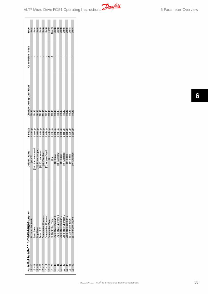
Par
amet
er N
um
ber
Par
amet
er D
escr
ipti
onD
efau
lt V
alue
2 S
etu
pC
han
ge D
uri
ng O
pera
tion
Con
vers
ion
Ind
exTy
pe13
- 0
0SL
Con
trol
ler
Mod
e[0
] O
ff1
set-
upTR
UE
-U
int8
13 -
01
Star
t Ev
ent
[39]
Sta
rt c
omm
and
1 se
t-up
TRU
E-
Uin
t813
- 0
2St
op E
vent
[40]
Driv
e st
oppe
d1
set-
upTR
UE
-U
int8
13 -
03
Rese
t SL
C[0
] D
o no
t re
set
1 se
t-up
TRU
E-
Uin
t813
- 1
0Co
mpa
rato
r O
pera
nd[0
] D
isab
led
1 se
t-up
TRU
E-
Uin
t813
- 1
1Co
mpa
rato
r O
pera
tor
[1]
Appr
oxEq
ual
1 se
t-up
TRU
E-
Uin
t813
- 1
2Co
mpa
rato
r Va
lue
01
set-
upTR
UE
-1In
t32
13 -
20
SL C
ontr
olle
r Ti
mer
0 s
1 se
t-up
TRU
E-1
Uin
t32
13 -
40
Logi
c Ru
le B
oole
an 1
[0]
Fals
e1
set-
upTR
UE
-U
int8
13 -
41
Logi
c Ru
le O
pera
tor
1[0
] D
isab
led
1 se
t-up
TRU
E-
Uin
t813
- 4
2Lo
gic
Rule
Boo
lean
2[0
] Fa
lse
1 se
t-up
TRU
E-
Uin
t813
- 4
3Lo
gic
Rule
Ope
rato
r 2
[0]
Dis
able
d1
set-
upTR
UE
-U
int8
13 -
44
Logi
c Ru
le B
oole
an 3
[0]
Fals
e1
set-
upTR
UE
-U
int8
13 -
51
SL C
ontr
olle
r Ev
ent
[0]
Fals
e1
set-
upTR
UE
-U
int8
13 -
52
SL C
ontr
olle
r Ac
tion
[0]
Dis
able
d1
set-
upTR
UE
-U
int8
6.2
.14
13
-**
Sm
art
Logi
c
VLT® Micro Drive FC 51 Operating Instructions 6 Parameter Overview
MG.02.A4.02 - VLT® is a registered Danfoss trademark 55
6

Par
amet
er N
um
ber
Par
amet
er D
escr
ipti
onD
efau
lt V
alue
2 S
etu
pC
han
ge D
uri
ng O
pera
tion
Con
vers
ion
Ind
exTy
pe14
- 0
1Sw
itchi
ng F
requ
ency
[1]
4.0
kHz
All s
et-u
psTR
UE
-U
int8
14 -
03
Ove
rmod
ulat
ion
[1]
On
All s
et-u
psFA
LSE
-U
int8
14 -
12
Func
tion
at M
ains
Im
bala
nce
[0]
Trip
All s
et-u
psTR
UE
-U
int8
14 -
20
Res
et M
ode
[0]
Man
ual r
eset
All s
et-u
psTR
UE
-U
int8
14 -
21
Auto
mat
ic R
esta
rt T
ime
10 s
All s
et-u
psTR
UE
0U
int1
614
- 2
2O
pera
tion
Mod
e[0
] N
orm
al o
pera
tion
1 se
t-up
TRU
E-
Uin
t814
- 2
6Ac
tion
At I
nver
ter
Faul
t[0
] Tr
ipAl
l set
-ups
TRU
E-
Uin
t814
- 4
1AE
O M
inim
um M
agne
tisat
ion
66 %
All s
et-u
psTR
UE
0U
int8
6.2.
1514
-**
Spe
cial
Fu
nct
ion
s
6 Parameter Overview VLT® Micro Drive FC 51 Operating Instructions
56 MG.02.A4.02 - VLT® is a registered Danfoss trademark
6

Par
amet
er N
um
ber
Par
amet
er D
escr
ipti
onD
efau
lt V
alue
2 S
etu
pC
han
ge D
uri
ng O
pera
tion
Con
vers
ion
Ind
exTy
pe15
- 0
0O
pera
ting
Tim
e0
1 se
t-up
TRU
E0
Uin
t32
15 -
01
Run
ning
Hou
rs0
1 se
t-up
TRU
E0
Uin
t32
15 -
02
kWh
Coun
ter
01
set-
upTR
UE
0U
int3
215
- 0
3Po
wer
Up'
s0
1 se
t-up
TRU
E0
Uin
t32
15 -
04
Ove
r Te
mp'
s0
1 se
t-up
TRU
E0
Uin
t16
15 -
05
Ove
r Vo
lt's
01
set-
upTR
UE
0U
int1
615
- 0
6Re
set
kWh
Coun
ter
[0]
Do
not
rese
t1
set-
upTR
UE
-U
int8
15 -
07
Rese
t Ru
nnin
g H
ours
Cou
nter
[0]
Do
not
rese
t1
set-
upTR
UE
-U
int8
15 -
30
Faul
t Lo
g: E
rror
Cod
e0
1 se
t-up
TRU
E0
Uin
t815
- 4
0FC
Typ
e
1 se
t-up
FALS
E0
Visi
bleS
trin
g15
- 4
1Po
wer
Sec
tion
1
set-
upFA
LSE
0Vi
sibl
eStr
ing
15 -
42
Volta
ge
1 se
t-up
FALS
E0
Visi
bleS
trin
g15
- 4
3SW
ID
Con
trol
Car
d
1 se
t-up
FALS
E0
Visi
bleS
trin
g15
- 4
6Fr
eque
ncy
Conv
erte
r O
rder
ing
No
1
set-
upFA
LSE
0Vi
sibl
eStr
ing
15 -
48
LCP
Id N
o
1 se
t-up
FALS
E0
Visi
bleS
trin
g15
- 5
1Fr
eque
ncy
Conv
erte
r Se
rial N
umbe
r
1 se
t-up
FALS
E0
Visi
bleS
trin
g
6.2.
1615
-**
Dri
ve I
nfo
rmat
ion
VLT® Micro Drive FC 51 Operating Instructions 6 Parameter Overview
MG.02.A4.02 - VLT® is a registered Danfoss trademark 57
6

Par
amet
er N
um
ber
Par
amet
er D
escr
ipti
onD
efau
lt V
alue
2 S
etu
pC
han
ge D
uri
ng O
pera
tion
Con
vers
ion
Ind
exTy
pe16
- 0
0Co
ntro
l Wor
d0
1 se
t-up
TRU
E0
Uin
t16
16 -
01
Refe
renc
e [U
nit]
01
set-
upTR
UE
-3In
t32
16 -
02
Refe
renc
e %
01
set-
upTR
UE
-1In
t16
16 -
03
Stat
us W
ord
01
set-
upTR
UE
0U
int1
616
- 0
5M
ain
Actu
al V
alue
[%
]0
1 se
t-up
TRU
E-2
Int1
616
- 1
0Po
wer
[kW
]0
1 se
t-up
TRU
E-3
Uin
t16
16 -
11
Pow
er [
hp]
01
set-
upTR
UE
-3U
int1
616
- 1
2M
otor
Vol
tage
01
set-
upTR
UE
0U
int1
616
- 1
3Fr
eque
ncy
01
set-
upTR
UE
-1U
int1
616
- 1
4M
otor
Cur
rent
01
set-
upTR
UE
-2U
int1
616
- 1
5Fr
eque
ncy
[%]
01
set-
upTR
UE
-1U
int1
616
- 1
8M
otor
The
rmal
01
set-
upTR
UE
0U
int8
16 -
30
DC
Link
Vol
tage
01
set-
upTR
UE
0U
int1
616
- 3
4H
eats
ink
Tem
p.0
1 se
t-up
TRU
E0
Uin
t816
- 3
5In
vert
er T
herm
al0
1 se
t-up
TRU
E0
Uin
t816
- 3
6In
v. N
om. C
urre
nt0
1 se
t-up
TRU
E-2
Uin
t16
16 -
37
Inv.
Max
. Cur
rent
01
set-
upTR
UE
-2U
int1
616
- 3
8SL
Con
trol
ler
Stat
e0
1 se
t-up
TRU
E0
Uin
t816
- 5
0Ex
tern
al R
efer
ence
01
set-
upTR
UE
-1In
t16
16 -
51
Puls
e Re
fere
nce
01
set-
upTR
UE
-1In
t16
16 -
52
Feed
back
[U
nit]
01
set-
upTR
UE
-3In
t32
16 -
60
Dig
ital i
nput
18,
19,2
7,33
01
set-
upTR
UE
0U
int1
616
- 6
1D
igita
l inp
ut 2
90
1 se
t-up
TRU
E0
Uin
t816
- 6
2An
alog
Inp
ut 5
3 (V
)0
1 se
t-up
TRU
E-2
Uin
t16
16 -
63
Anal
og I
nput
53
(mA)
01
set-
upTR
UE
-2U
int1
616
- 6
4An
alog
Inp
ut 6
00
1 se
t-up
TRU
E-2
Uin
t16
16 -
65
Anal
og O
utpu
t 42
[m
A]0
1 se
t-up
TRU
E-2
Uin
t16
16 -
68
Puls
e in
put
3320
1 se
t-up
TRU
E0
Uin
t16
16 -
71
Rela
y O
utpu
t [b
in]
01
set-
upTR
UE
0U
int8
16 -
72
Coun
ter
A0
1 se
t-up
TRU
E0
Int1
616
- 7
3Co
unte
r B
01
set-
upTR
UE
0In
t16
16 -
86
FC P
ort
REF
10
1 se
t-up
TRU
E0
Int1
616
- 9
0Al
arm
Wor
d0
1 se
t-up
TRU
E0
Uin
t32
16 -
92
War
ning
Wor
d0
1 se
t-up
TRU
E0
Uin
t32
16 -
94
Ext.
Sta
tus
Wor
d0
1 se
t-up
TRU
E0
Uin
t32
6.2.
1716
-**
Dat
a R
eado
uts
6 Parameter Overview VLT® Micro Drive FC 51 Operating Instructions
58 MG.02.A4.02 - VLT® is a registered Danfoss trademark
6

7 TroubleshootingN
o.D
escr
iptio
nW
arni
ngAl
arm
Trip
Loc
kEr
ror
Caus
e of
Pro
blem
2Li
ve z
ero
erro
rX
X
Si
gnal
on
term
inal
53
or 6
0 is
less
tha
n 50
% o
f va
lue
set
in p
ar. 6
-10,
6-1
2 an
d 6-
22.
4M
ains
pha
se lo
ss1)
XX
X
Mis
sing
pha
se o
n su
pply
sid
e, o
r to
o hi
gh v
olta
ge im
bala
nce.
Che
ck s
uppl
y vo
ltage
.7
DC
over
vol
tage
1)X
X
In
term
edia
te c
ircui
t vo
ltage
exc
eeds
lim
it.8
DC
unde
r vo
ltage
1)X
X
In
term
edia
te c
ircui
t vo
ltage
dro
ps b
elow
“vo
ltage
war
ning
low
” lim
it.9
Inve
rter
ove
rload
edX
X
M
ore
than
100
% lo
ad for
too
long
.10
Mot
or E
TR o
ver
tem
pera
ture
XX
Mot
or is
too
hot
due
to
mor
e th
an 1
00%
load
for
too
long
.11
Mot
or t
herm
isto
r ov
er t
empe
ratu
reX
X
Th
erm
isto
r or
the
rmis
tor
conn
ectio
n is
dis
conn
ecte
d.12
Torq
ue li
mit
X
Torq
ue e
xcee
ds v
alue
set
in e
ither
par
. 4-1
6 or
4-1
7.13
Ove
r Cu
rren
tX
XX
In
vert
er p
eak
curr
ent
limit
is e
xcee
ded.
14Ea
rth
faul
t
XX
D
isch
arge
fro
m o
utpu
t ph
ases
to
grou
nd.
16Sh
ort
Circ
uit
X
X
Shor
t-ci
rcui
t in
mot
or o
r on
mot
or t
erm
inal
s.17
Cont
rol w
ord
timeo
utX
X
N
o co
mm
unic
atio
n to
fre
quen
cy c
onve
rter
.25
Brak
e re
sist
or s
hort
-circ
uite
d
XX
Br
ake
resi
stor
is s
hort
-circ
uite
d, t
hus
brak
e fu
nctio
n is
dis
conn
ecte
d.27
Brak
e ch
oppe
r sh
ort-
circ
uite
d
XX
Br
ake
tran
sist
or is
sho
rt-c
ircui
ted,
thu
s br
ake
func
tion
is d
isco
nnec
ted.
28Br
ake
chec
k
X
Br
ake
resi
stor
is n
ot c
onne
cted
/wor
king
29Po
wer
boa
rd o
ver
tem
pX
XX
H
eat-
sink
cut
-out
tem
pera
ture
has
bee
n re
ache
d.30
Mot
or p
hase
U m
issi
ng
XX
M
otor
pha
se U
is m
issi
ng. C
heck
the
pha
se.
31M
otor
pha
se V
mis
sing
X
X
Mot
or p
hase
V is
mis
sing
. Che
ck t
he p
hase
.32
Mot
or p
hase
W m
issi
ng
XX
M
otor
pha
se W
is m
issi
ng. C
heck
the
pha
se.
38In
tern
al fau
lt
XX
Co
ntac
t lo
cal D
anfo
ss s
uppl
ier.
47Co
ntro
l Vol
tage
Fau
ltX
XX
24
V D
C m
ay b
e ov
erlo
aded
.51
AMT
chec
k U
nom a
nd I
nom
X
Wro
ng s
ettin
g fo
r m
otor
vol
tage
and
/or
mot
or c
urre
nt.
52AM
T lo
w I
nom
X
Mot
or c
urre
nt is
too
low
. Che
ck s
ettin
gs.
59Cu
rren
t lim
itX
VL
T ov
erlo
ad.
63M
echa
nica
l Bra
ke L
ow
X
Ac
tual
mot
or c
urre
nt h
as n
ot e
xcee
ded
“rel
ease
bra
ke”
curr
ent w
ithin
“st
art d
elay
” tim
ew
indo
w.
80D
rive
Initi
alis
ed t
o D
efau
lt Va
lue
X
All p
aram
eter
set
tings
are
initi
aliz
ed t
o de
faul
t se
ttin
gs.
84Th
e co
nnec
tion
betw
een
driv
e an
d LC
P is
lost
X
No
com
mun
icat
ion
betw
een
LCP
and
freq
uenc
y co
nver
ter
85Bu
tton
dis
able
d
XSe
e pa
ram
eter
gro
up 0
-4*
LCP
86Co
py f
ail
X
An e
rror
occ
urre
d w
hile
cop
ying
fro
m f
requ
ency
con
vert
er t
o LC
P or
vic
e ve
rsa.
87LC
P da
ta in
valid
X
Occ
urs
whe
n co
pyin
g fr
om L
CP if
the
LCP
con
tain
s er
rone
ous
data
- o
r if
no d
ata
was
uplo
aded
to
the
LCP.
88LC
P da
ta n
ot c
ompa
tible
X
Occ
urs
whe
n co
pyin
g fr
om L
CP if
dat
a ar
e m
oved
bet
wee
n fr
eque
ncy
conv
erte
rs w
ithm
ajor
diff
eren
ces
in s
oftw
are
vers
ions
.89
Para
met
er r
ead
only
X
Occ
urs
whe
n tr
ying
to
writ
e to
a r
ead-
only
par
amet
er.
90Pa
ram
eter
dat
abas
e bu
sy
XLC
P an
d RS
485
conn
ectio
n ar
e tr
ying
to
upda
te p
aram
eter
s si
mul
tane
ousl
y.91
Para
met
er v
alue
is n
ot v
alid
in t
his
mod
e
XO
ccur
s w
hen
tryi
ng t
o w
rite
an il
lega
l val
ue t
o a
para
met
er.
92Pa
ram
eter
val
ue e
xcee
ds t
he m
in/m
ax li
mits
X
Occ
urs
whe
n tr
ying
to
set
a va
lue
outs
ide
the
rang
e.nw
run
Not
Whi
le R
UN
ning
X
Para
met
er c
an o
nly
be c
hang
ed w
hen
the
mot
or is
sto
pped
.Er
r.A
wro
ng p
assw
ord
was
ent
ered
X
Occ
urs
whe
n us
ing
a w
rong
pas
swor
d fo
r ch
angi
ng a
pas
swor
d-pr
otec
ted
para
met
er.
1) T
hese
fau
lts m
ay b
e ca
used
by
mai
ns d
isto
rtio
ns.
Inst
allin
g D
anfo
ss L
ine
Filte
r m
ay r
ectif
y th
is p
robl
em.
Tabl
e 7.
1: W
arni
ngs
and
Alar
ms
Code
list
VLT® Micro Drive FC 51 Operating Instructions 7 Troubleshooting
MG.02.A4.02 - VLT® is a registered Danfoss trademark 59
7

7.1.1 Alarm, Warning and Extended Status Word
Par 1690 Par 1692 Par 1694
Bit Hex Dec AlarmWord WarningWord ExtendedStatusWord
0 1 1 Brake check Ramping
1 2 2 Pwr.card temp Pwr.card temp
2 4 4 Earth Fault Start CW/CCW
3 8 8 Slow down
4 10 16 Ctrl.word TO Ctrl.word TO Catch up
5 20 32 Over Current Over Current
6 40 64 Torque limit
7 80 128 Motor th over Motor th over Output current high
8 100 256 Motor ETR over Motor ETR over Output current low
9 200 512 Inverter overload Inverter overload
10 400 1024 DC under volt DC under volt
11 800 2048 DC over volt DC over volt
12 1000 4096 Short Circuit
13 2000 8192 Braking
14 4000 16384 Mains ph. loss Mains ph. loss
15 8000 32768 "AMT Not OK" OVC active
16 10000 65536 Live zero error Live zero error AC brake
17 20000 131072 Internal fault
18 40000 262144
19 80000 524288 U phase loss
20 100000 1048576 V phase loss
21 200000 2097152 W phase loss
22 400000 4194304
23 800000 8388608 Control Voltage Fault
24 1000000 16777216
25 2000000 33554432 Current limit
26 4000000 67108864 Brake resistor shortcircuit
27 8000000 134217728 Brake IGBT shortcircuit
28 10000000 268435456 MotorPhaseMissing
29 20000000 536870912 Drive initialised
30 40000000 1073741824 Undefined
31 80000000 2147483648 Mech. brake low DatabaseBusy
7 Troubleshooting VLT® Micro Drive FC 51 Operating Instructions
60 MG.02.A4.02 - VLT® is a registered Danfoss trademark
7

8 Specifications
8.1 Mains Supply
8.1.1 Mains Supply 1 x 200 - 240 VAC
Normal overload 150% for 1 minute Frame M1 Frame M1 Frame M1 Frame M2 Frame M3Frequency converterTypical Shaft Output [kW]
P0K180.18
P0K370.37
P0K750.75
P1K51.5
P2K22.2
Typical Shaft Output [HP] 0.25 0.5 1 2 3Output current
Continuous (3 x 200-240 V ) [A] 1.2 2.2 4.2 6.8 9.6Intermittent (3 x 200-240 V ) [A] 1.8 3.3 6.3 10.2 14.4Max. cable size:(mains, motor) [mm2 /AWG] 4/10
Max. input currentContinuous (1 x 200-240 V ) [A] 3.3 6.1 11.6 18.7 26.4Intermittent (1 x 200-240 V ) [A] 4.5 8.3 15.6 26.4 37.0Max. pre-fuses [A] See Section FusesEnvironmentEstimated power loss at rated load [W],Best case/Typical1)
12.5/15.5
20.0/25.0
36.5/44.0
61.0/67.0 81.0/85.1
Weight enclosure IP20 [kg] 1.1 1.1 1.1 1.6 3.0EfficiencyBest case/Typical1)
95.6/94.5
96.5/95.6
96.6/96.0
97.0/96.7 96.9/97.1
Table 8.1: Mains supply 1 x 200 - 240 VAC
8.1.2 Mains Supply 3 x 200 - 240 VAC
Normal overload 150% for 1 minute Frame M1 Frame M1 Frame M1 Frame M2 Frame M3 Frame M3Frequency converterTypical Shaft Output [kW]
P0K250.25
P0K370.37
P0K750.75
P1K51.5
P2K22.2
P3K73.7
Typical Shaft Output [HP] 0.33 0.5 1 2 3 5Output current
Continuous (3 x 200-240 V ) [A] 1.5 2.2 4.2 6.8 9.6 15.2Intermittent (3 x 200-240 V ) [A] 2.3 3.3 6.3 10.2 14.4 22.8Max. cable size: (mains, motor) [mm2 /AWG] 4/10
Max. input current Continuous (3 x 200-240 V ) [A] 2.4 3.5 6.7 10.9 15.4 24.3Intermittent (3 x 200-240 V ) [A] 3.2 4.6 8.3 14.4 23.4 35.3Max. pre-fuses [A] See Section FusesEnvironment Estimated power loss at rated load [W],Best case/Typical1)
14.0/20.0
19.0/24.0
31.5/39.5
51.0/57.0
72.0/77.1
115.0/122.8
Weight enclosure IP20 [kg] 1.1 1.1 1.1 1.6 3.0 3.0EfficiencyBest case/Typical1)
96.4/94.9
96.7/95.8
97.1/96.3
97.4/97.2
97.2/97.4
97.3/97.4
Table 8.1: Mains supply 3 x 200 - 240 VAC
1. Power loss at rated load conditions.
VLT® Micro Drive FC 51 Operating Instructions 8 Specifications
MG.02.A4.02 - VLT® is a registered Danfoss trademark 61
8
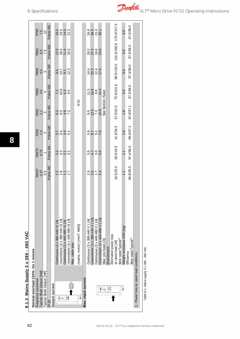
Nor
mal
ove
rloa
d 1
50
% f
or 1
min
ute
Freq
uenc
y co
nver
ter
Typi
cal S
haft
Out
put
[kW
]P0
K37
0.37
P0K7
50.
75P1
K51.
5P2
K22.
2P3
K03.
0P4
K04.
0P5
K55.
5P7
K57.
5Ty
pica
l Sha
ft O
utpu
t [H
P]0.
51
23
45
7.5
10IP
20
Fr
ame
M1
Fram
e M
1Fr
ame
M2
Fram
e M
2Fr
ame
M3
Fram
e M
3Fr
ame
M3
Fram
e M
3O
utp
ut
curr
ent
Cont
inuo
us (
3 x
380-
440
V) [
A]1.
22.
23.
75.
37.
29.
012
.015
.5In
term
itten
t (3
x 3
80-4
40 V
) [A
]1.
83.
35.
68.
010
.813
.718
.023
.5Co
ntin
uous
(3
x 44
0-48
0 V)
[A]
1.1
2.1
3.4
4.8
6.3
8.2
11.0
14.0
Inte
rmitt
ent
(3 x
440
-480
V)
[A]
1.7
3.2
5.1
7.2
9.5
12.3
16.5
21.3
Max
. cab
le s
ize:
(mai
ns, m
otor
) [m
m2 /
AW
G]
4/10
Max
. in
put
curr
ent
Cont
inuo
us (
3 x
380-
440
V )
[A]
1.9
3.5
5.9
8.5
11.5
14.4
19.2
24.8
Inte
rmitt
ent
(3 x
380
-440
V )
[A]
2.6
4.7
8.7
12.6
16.8
20.2
27.4
36.3
Cont
inuo
us (
3 x
440-
480
V )
[A]
1.7
3.0
5.1
7.3
9.9
12.4
16.6
21.4
Inte
rmitt
ent
(3 x
440
-480
V )
[A]
2.3
4.0
7.5
10.8
14.4
17.5
23.6
30.1
Max
. pre
-fus
es [
A]Se
e Se
ctio
n Fu
ses
Envi
ronm
ent
Estim
ated
pow
er lo
ssat
rat
ed lo
ad [
W]
Best
cas
e/Ty
pica
l1)18
.5/2
5.5
28.5
/43.
541
.5/5
6.5
57.5
/81.
575
.0/1
01.6
98.5
/133
.513
1.0/
166.
817
5.0/
217.
5
Wei
ght
encl
osur
e IP
20 [
kg]
1.1
1.1
1.6
1.6
3.0
3.0
3.0
3.0
Effic
ienc
yBe
st c
ase/
Typi
cal1)
96.8
/95.
597
.4/9
6.0
98.0
/97.
297
.9/9
7.1
97.2
/98.
097
.3/9
8.0
97.5
/98.
097
.5/9
8.0
1.Po
wer
loss
at
rate
d lo
ad c
ondi
tions
.
Tabl
e 8.
1: M
ains
sup
ply
3 x
380
- 48
0 VA
C
8.1.
3M
ain
s Su
pply
3 x
38
0 -
480
VA
C
8 Specifications VLT® Micro Drive FC 51 Operating Instructions
62 MG.02.A4.02 - VLT® is a registered Danfoss trademark
8

8.2 Other Specifications
Protection and Features:
• Electronic thermal motor protection against overload.
• Temperature monitoring of the heatsink ensures that the frequency converter trips in case of overtemperature
• The frequency converter is protected against short-circuits on motor terminals U, V, W.
• If a motor phase is missing, the frequency trips and issues an alarm.
• If a mains phase is missing, the frequency converter trips or issues a warning (depending on the load).
• Monitoring of the intermediate circuit voltage ensures that the frequency converter trips if the intermediate circuit voltage is too low or too high.
• The frequency converter is protected against earth faults on motor terminals U, V, W.
Mains supply (L1/L, L2, L3/N):
Supply voltage 200-240 V ±10%
Supply voltage 380-480 V ±10%
Supply frequency 50/60 Hz
Max. imbalance temporary between mains phases 3.0 % of rated supply voltage
True Power Factor (λ) ≥ 0.4 nominal at rated load
Displacement Power Factor (cosφ) near unity (> 0.98)
Switching on input supply L1/L, L2, L3/N (power-ups) maximum 2 times/min.
Environment according to EN60664-1 overvoltage category III/pollution degree 2
The unit is suitable for use on a circuit capable of delivering not more than 100.000 RMS symmetrical Amperes, 240/480 V maximum.
Motor output (U, V, W):
Output voltage 0 - 100% of supply voltage
Output frequency 0-200 Hz (VVC+), 0-400 Hz (u/f)
Switching on output Unlimited
Ramp times 0.05 - 3600 sec.
Cable lengths and cross sections:
Max. motor cable length, screened/armoured (EMC correct installation) 15 m
Max. motor cable length, unscreened/unarmoured 50 m
Max. cross section to motor, mains, load sharing and brake *
Maximum cross section to control terminals, rigid wire 1.5 mm2/16 AWG (2 x 0.75 mm2)
Maximum cross section to control terminals, flexible cable 1 mm2/18 AWG
Maximum cross section to control terminals, cable with enclosed core 0.5 mm2/20 AWG
Minimum cross section to control terminals 0.25 mm2
* See tables for mains supply for more information!
Digital inputs (Pulse/enocder inputs):
Programmable digital inputs (Pulse/encoder) 5 (1)
Terminal number 18, 19, 27, 29, 33,
Logic PNP or NPN
Voltage level 0 - 24 V DC
Voltage level, logic'0' PNP < 5 V DC
Voltage level, logic'1' PNP > 10 V DC
Voltage level, logic '0' NPN > 19 V DC
Voltage level, logic '1' NPN < 14 V DC
Maximum voltage on input 28 V DC
Input resistance, Ri approx. 4 k
Max. pulse frequency at terminal 33 5000 Hz
Min. pulse frequency at terminal 33 20 Hz
VLT® Micro Drive FC 51 Operating Instructions 8 Specifications
MG.02.A4.02 - VLT® is a registered Danfoss trademark 63
8

Analog inputs:
Number of analog inputs 2
Terminal number 53, 60
Voltage level 0 -10 V
Input resistance, Ri approx. 10 kΩ
Max. voltage 20 V
Current level 0/4 to 20 mA (scaleable)
Input resistance, Ri approx. 200 Ω
Max. current 30 mA
Analog output:
Number of programmable analog outputs 1
Terminal number 42
Current range at analog output 0/4 - 20 mA
Max. resistor load to common at analog output 500 Ω
Accuracy on analog output Max. error: 0.8 % of full scale
Resolution on analog output 8 bit
The analog output is galvanically isolated from the supply voltage (PELV) and other high-voltage terminals.
Control card, RS-485 serial communication:
Terminal number 68 (P,TX+, RX+), 69 (N,TX-, RX-)
Terminal number 61 Common for terminals 68 and 69
The RS-485 serial communication circuit is functionally separated from other central circuits and galvanically isolated from the supply voltage (PELV).
Control card, 24 V DC output:
Terminal number 12
Max. load 200 mA
Relay output:
Programmable relay output 1
Relay 01 Terminal number 01-03 (break), 01-02(make)
Max. terminal load (AC-1)1) on 01-02 (NO) (Resistive load) 250 V AC, 2 A
Max. terminal load (AC-15)1) on 01-02 (NO) (Inductive load @ cosφ 0.4) 250 V AC, 0.2 A
Max. terminal load (DC-1)1) on 01-02 (NO) (Resistive load) 30 V DC, 2 A
Max. terminal load (DC-13)1) on 01-02 (NO) (Inductive load) 24 V DC, 0.1A
Max. terminal load (AC-1)1) on 01-03 (NC) (Resistive load) 250 V AC, 2 A
Max. terminal load (AC-15)1) on 01-03 (NC) (Inductive load @ cosφ 0.4) 250 V AC, 0.2A
Max. terminal load (DC-1)1) on 01-03 (NC) (Resistive load) 30 V DC, 2 A
Min. terminal load on 01-03 (NC), 01-02 (NO) 24 V DC 10 mA, 24 V AC 20 mA
Environment according to EN 60664-1 overvoltage category III/pollution degree 2
1) IEC 60947 part 4 and 5
Control card, 10 V DC output:
Terminal number 50
Output voltage 10.5 V ±0.5 V
Max. load 25 mA
The 10 V DC supply is galvanically isolated from the supply voltage (PELV) and other high-voltage terminals.
Surroundings:
Enclosure IP 20
Enclosure kit available IP 21
Enclosure kit available TYPE 1
Vibration test 1.0 g
Max. relative humidity 5% - 95%(IEC 60721-3-3; Class 3K3 (non-condensing) during operation
Aggressive environment (IEC 60721-3-3), coated class 3C3
Test method according to IEC 60068-2-43 H2S (10 days)
8 Specifications VLT® Micro Drive FC 51 Operating Instructions
64 MG.02.A4.02 - VLT® is a registered Danfoss trademark
8

Ambient temperature Max. 40 °C
Derating for high ambient temperature, see section on special conditions
Minimum ambient temperature during full-scale operation 0 °C
Minimum ambient temperature at reduced performance - 10 °C
Temperature during storage/transport -25 - +65/70 °C
Maximum altitude above sea level without derating 1000 m
Maximum altitude above sea level with derating 3000 m
Derating for high altitude, see section on special conditions
EMC standards, Emission EN 61800-3, EN 61000-6-3/4, EN 55011, IEC 61800-3
EMC standards, Immunity
EN 61800-3, EN 61000-6-1/2, EN 61000-4-2, EN 61000-4-3,
EN 61000-4-4, EN 61000-4-5, EN 61000-4-6
See section on special conditions
8.3 Special Conditions
8.3.1 The Purpose of Derating
Derating must be taken into account when using the frequency converter at low air pressure (heights), at low speeds or at high ambient temperature.
The required action is described in this section.
8.3.2 Derating for Ambient Temperature
The ambient temperature measured over 24 hours should be at least 5 °C lower than the max. ambient temperature.
If the frequency converter is operated at high ambient temperature, the continuous output current should be decreased.
The frequency converter has been designed for operation at max 50 °C ambient temperature with one motor size smaller than nominal. Continuous
operation at full load at 50 °C ambient temperature will reduce the lifetime of the frequency converter.
8.3.3 Derating for Low Air Pressure
The cooling capability of air is decreased at low air pressure.
For altitudes above 2000 m, please contact Danfoss regarding PELV.
Below 1000 m altitude no de-rating is necessary but above 1000 m the ambient temperature or the maximum output current should be decreased.
Decrease the output by 1% per 100 m altitude above 1000 m or reduce the max. ambient temperature by 1 degree per 200 m
8.3.4 Derating for Running at Low Speeds
When a motor is connected to at frequency converter, it is necessary to check that the cooling of the motor is adequate.
A problem may occur at low speeds in constant torque applications. Running continuously at low speeds – below half the nominal motor speed – may
require additional air cooling. Alternatively, choose a larger motor (one size up).
VLT® Micro Drive FC 51 Operating Instructions 8 Specifications
MG.02.A4.02 - VLT® is a registered Danfoss trademark 65
8

8.4 Options for VLT Micro Drive FC 51
Ordering No Description
132B0100 VLT Control Panel LCP 11 w/o
potentiometer
132B0101 VLT Control Panel LCP 12 with
potentiometer
132B0102 Remote Mounting Kit for LCP incl.
3 m cable, IP55 with LCP 11, IP21 with LCP 12.
132B0103 Nema Type 1 kit for M1 frame
132B0104 Nema Type 1 kit for M2 frame
132B0105 Nema Type 1 kit for M3 frame
132B0106 De-coupling plate kit for M1 and M2 frames
132B0107 De-coupling plate kit for M3 frame
132B0108 IP21 for M1 frame
132B0109 IP21 for M2 frame
132B0110 IP21 for M3 frame
132B0111 DIN rail mounting kit for M1 frame
Danfoss Line Filters and brake resistors are available upon request.
8 Specifications VLT® Micro Drive FC 51 Operating Instructions
66 MG.02.A4.02 - VLT® is a registered Danfoss trademark
8

Index
AActive Set-up 17
Active Set-up 41, 46
Alarm, Warning And Extended Status Word 60
Ambient Temperature 65
Analog In/out 52
Analog Inputs 63
Analog Output 64
Automatic Motor Tuning (amt) 21
BBrake Resistor 48
Brake Resistor (ohm) 41
Brake Resistor Short-circuited 59
Brakes 48
Bus Termination 15
CCable Lengths And Cross Sections 63
Clearance 9
Comm. And Options 54
Configuration Mode 22
Control Card, 10 V Dc Output 64
Control Card, 24 V Dc Output 64
Control Card, Rs-485 Serial Communication: 64
Control Terminals 15
Control Word According To Fc Profile 35
Controllers 53
Conversion Index 45
DDanfoss Fc Control Profile 35
Data Readouts 58
Dc-brake 42
Dc-brake 41
De-coupling Plate Kit 66
Derating For Ambient Temperature 65
Derating For Low Air Pressure 65
Derating For Running At Low Speeds 65
Digital In/out 51
Digital Inputs (pulse/enocder Inputs): 63
Digital Inputs: 63
Din Rail Mounting Kit 10, 66
Display 17
Disposal Instruction 8
Drive Information 57
EEarth Leakage Current 5, 7
Edit Set-up 17
Edit Set-up 41, 46
Electronic Waste 8
Emc-correct Installation 12
Explanation Of The Control Bits 35
Explanation Of The Status Bits 38
FFrequency Converter With Modbus Rtu 25
Function Codes Supported By Modbus Rtu 29
Fuses 11
VLT® Micro Drive FC 51 Operating Instructions Index
MG.02.A4.02 - VLT® is a registered Danfoss trademark 67

HHand Mode 42
Hand Mode 47
How To Connect 11
IIndicator Lights 18
Ip21 66
Isolated Mains Source 7
It Mains 7
LLcp 11 17
Lcp 12 17
Leakage Current 7
Limits/warnings 50
Load Compensation 41, 47
Load Sharing/brake 16
Load/motor 47
MMain Menu 18, 24
Mains Connection 12
Mains Supply 61
Mains Supply (l1/l, L2, L3/n) 63
Mains Supply 1 X 200 - 240 Vac 61
Mains Supply 3 X 200 - 240 Vac 61
Mains Supply 3 X 380 - 480 Vac 62
Max. Reference 22
Maximum Reference 21
Mct-10 Set-up Software 17
Mechanical Dimensions 10
Mechanical Installation 9
Min. Reference 22
Minimum Reference 21
Modbus Rtu 25
Modbus Rtu Message Framing Structure 26
Modbus Rtu Overview 25
Motor Connection 13
Motor Current 20
Motor Direction 18
Motor Frequency 20
Motor Nominal Speed 21
Motor Output (u, V, W): 63
Motor Overload Protection 7
Motor Phase 42, 50
Motor Power 20
Motor Protection 63
Motor Speed High Limit 22
Motor Speed Low Limit 22
Motor Temperature 41
Motor Voltage 20
NNavigation Keys 19
OOperation Keys 19
Operation/display 46
Options 66
Options For Vlt Micro Drive Fc 51 66
Other Specifications 63
Index VLT® Micro Drive FC 51 Operating Instructions
68 MG.02.A4.02 - VLT® is a registered Danfoss trademark

Output Performance (u, V, W) 63
Overcurrent Protection 11
Over-voltage Control 41, 48
PParameter Number 18
Parameter Overview 41
Power Circuit - Overview 16
Preset Reference 22
Process Cl Feedback Resource 23
Process Feed Forward Factor 23
Process Pi Anti Windup 23
Process Pi Integral Time 23
Process Pi Normal/inverse 23
Process Pi Proportional Gain 23
Process Pi Start Speed 23
Protection 11
Protection And Features 63
QQuick Menu 18, 19
Quick Menu Parameters 20
RRamp1 Ramp-down Time 22
Ramp1 Ramp-up Time 22
Readout Mode 18
Reference/ramps 49
Relay Output 64
Remote Mounting Kit 66
Residual Current Device 7
SS200 Switches 1-4 15
Serial Communication 19
Set-up Number 17
Set-up Software 17
Side-by-side Installation 9
Slip Compensation 41, 47
Smart Logic 55
Special Conditions 65
Special Functions 56
Specifications 61
Status Menu 18, 19
Status Word According To Fc Profile (stw) 37
Surroundings 64
Switches 15
TTemplate For Drilling 10
Terminal 60 Filter Time Constant 23
Terminal 60 High Current 23
Terminal 60 High Feedback Value 23
Terminal 60 Low Current 22
Terminal 60 Low Feedback Value 23
Thermistor 41
Thermistor Resource 47
Troubleshooting 59
UUl Compliance 11
Unit 18
VLT® Micro Drive FC 51 Operating Instructions Index
MG.02.A4.02 - VLT® is a registered Danfoss trademark 69

VValue 18
Vlt Control Panel Lcp 11 66
Vlt Control Panel Lcp 12 66
Voltage Level 63
WWarnings And Alarms 59
Index VLT® Micro Drive FC 51 Operating Instructions
70 MG.02.A4.02 - VLT® is a registered Danfoss trademark