1.1.1 mechanisms
DESCRIPTION
1.1.1 Mechanisms. Simple Machines 1 st , 2 nd , & 3 rd class Levers Wheel & Axle. Quietly read and decide what type of learner you may be. Once you have decided, privately write your choice on the sticky note provided. (1) I do it, build it, then I look at it to make it better. - PowerPoint PPT PresentationTRANSCRIPT
SIMPLE MACHINES1ST, 2ND, & 3RD CLASS LEVERS
WHEEL & AXLE
1.1.1 Mechanisms

Quietly read and decide what type of learner you may be. Once you have decided, privately write your choice on the sticky note
provided.
(1) I do it, build it, then I look at it to make it better.
(2) I need to draw/write out my ideas before I start. (3) I work best talking about my ideas with others and make a plan before I start. I then grouped them from their own number choice.
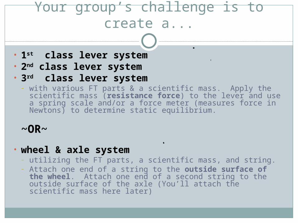
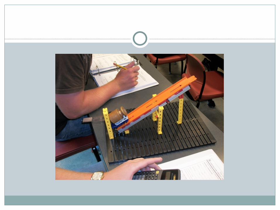
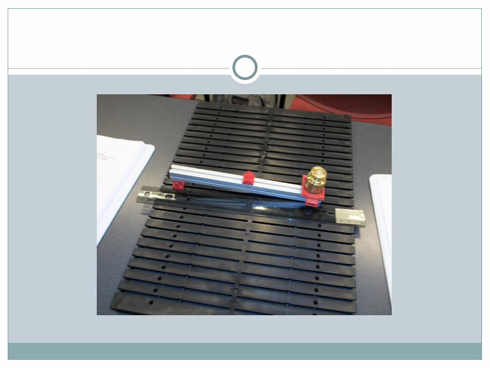
Your group’s challenge is to create a...
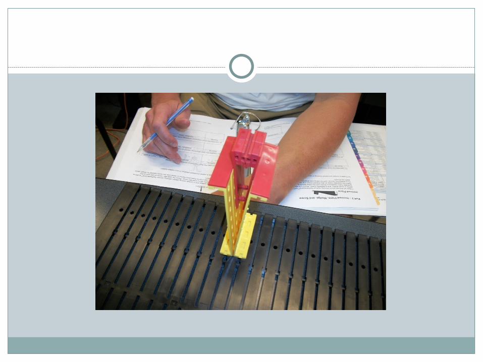
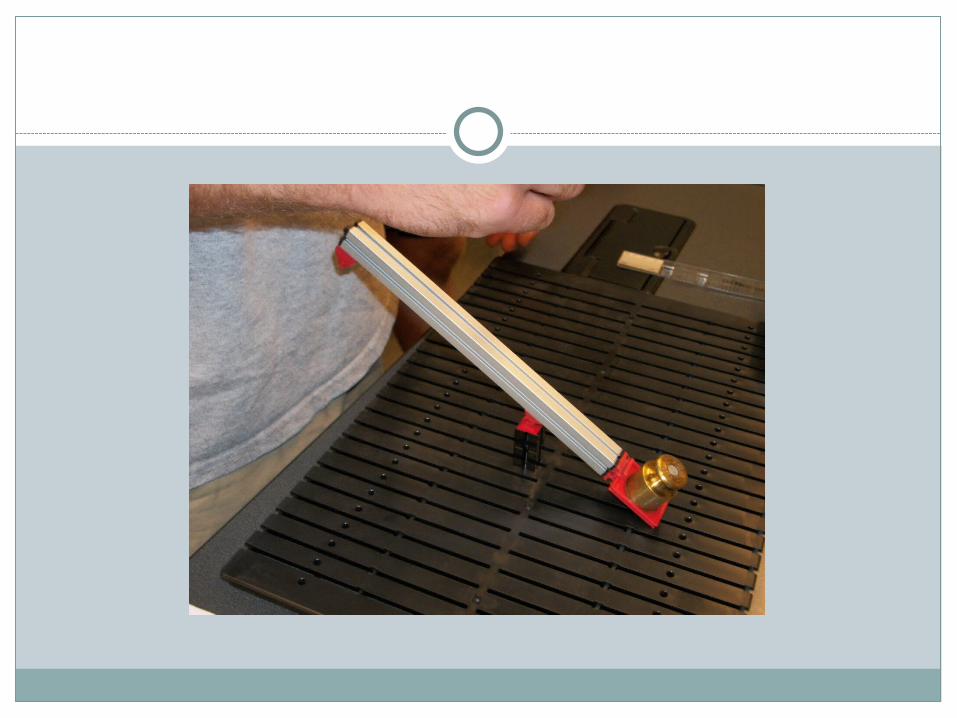
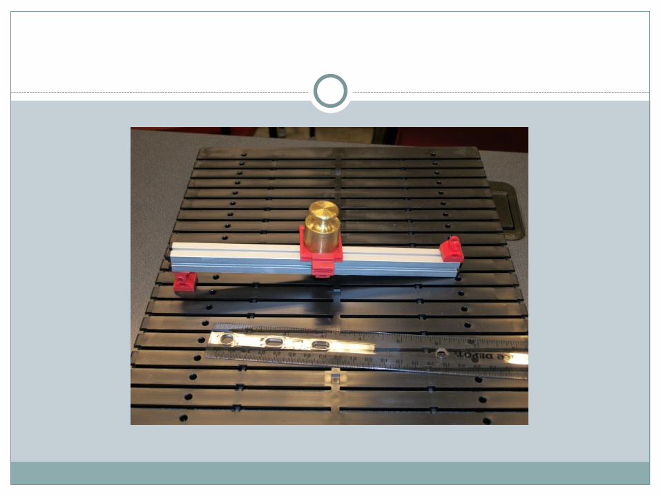
• 1st class lever system• 2nd class lever system• 3rd class lever system
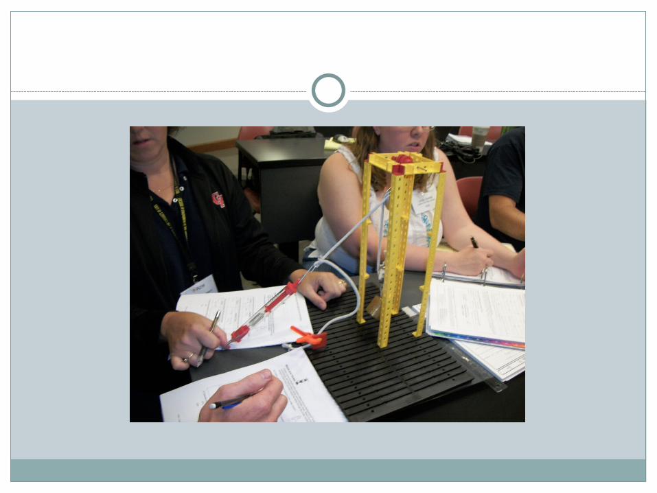
– with various FT parts & a scientific mass. Apply the scientific mass (resistance force) to the lever and use a spring scale and/or a force meter (measures force in Newtons) to determine static equilibrium.
~OR~
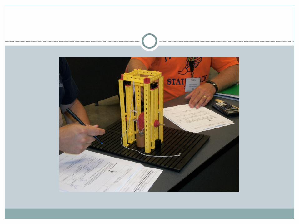
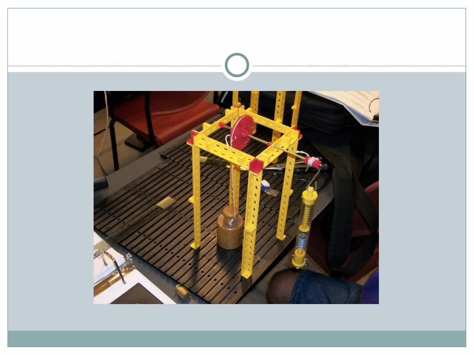
• wheel & axle system– utilizing the FT parts, a scientific mass, and string. – Attach one end of a string to the outside surface of the
wheel. Attach one end of a second string to the outside surface of the axle (You’ll attach the scientific mass here later)

You want me to do WHAT????
Build a simple machine…we’ll be testing it soon for MA (AMA, IMA, and Efficiency…)
Here’s some ideas to get you started…


(YOU WON’T USE ALL/MANY OF THESE FOR THE SIMPLE MACHINES, BUT IT GIVES YOU SOME
IDEAS!)
Hints on how these FTs go together?

Universal Joint
Transmits power when shafts are not in line
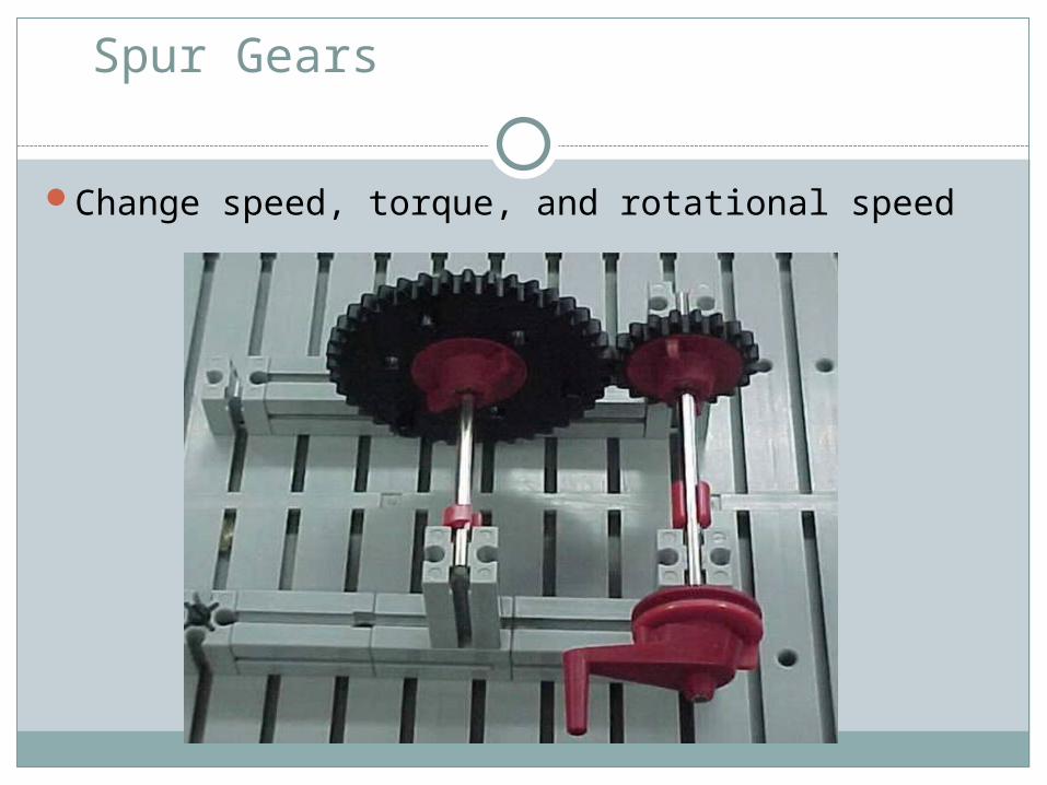
Spur Gears
Change speed, torque, and rotational speed
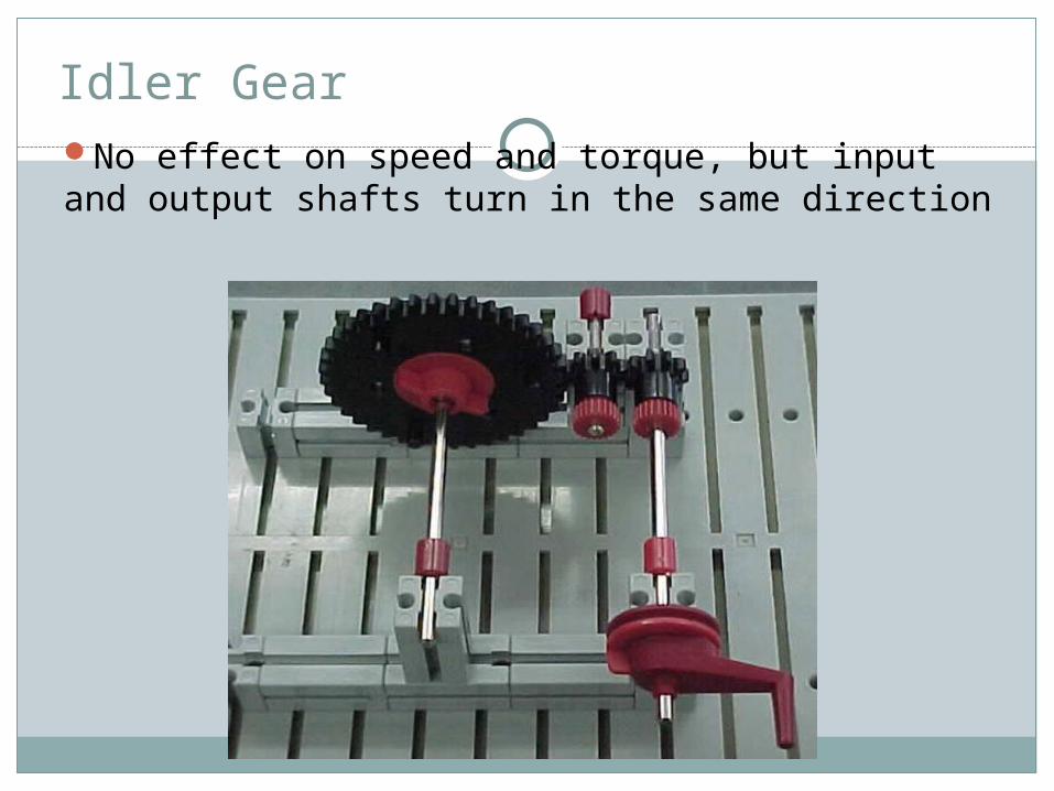
Idler GearNo effect on speed and torque, but input and output shafts turn in the same direction
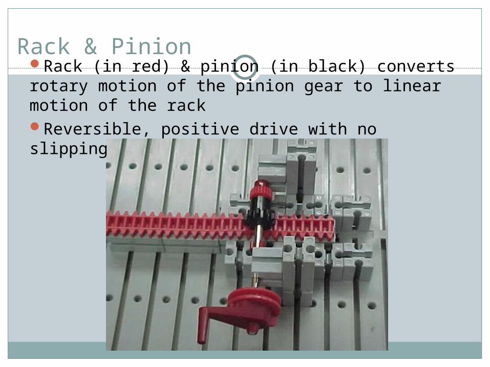
Rack & PinionRack (in red) & pinion (in black) converts rotary motion of the pinion gear to linear motion of the rackReversible, positive drive with no slipping
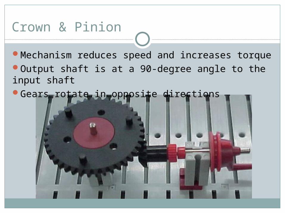
Crown & Pinion
Mechanism reduces speed and increases torqueOutput shaft is at a 90-degree angle to the input shaftGears rotate in opposite directions
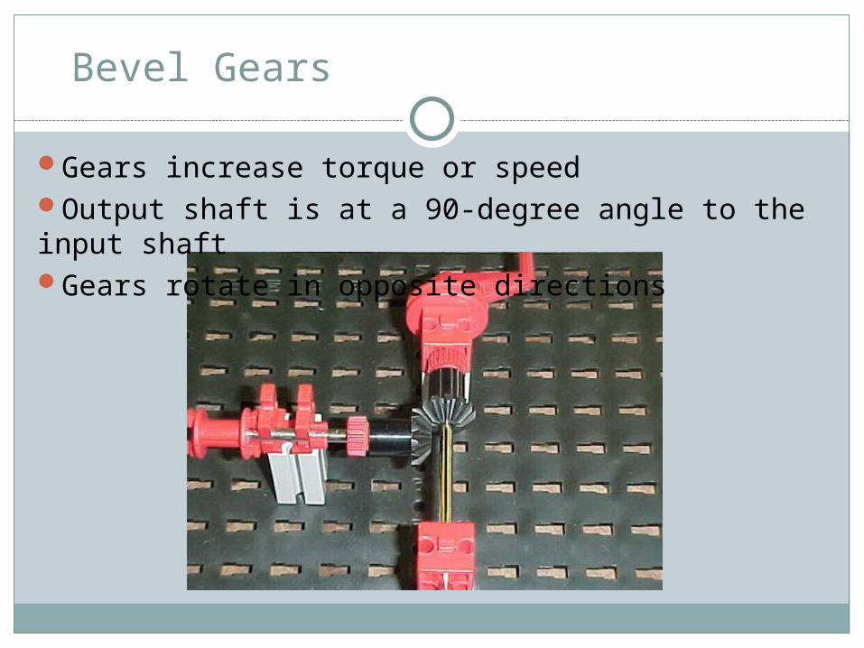
Bevel Gears
Gears increase torque or speedOutput shaft is at a 90-degree angle to the input shaftGears rotate in opposite directions
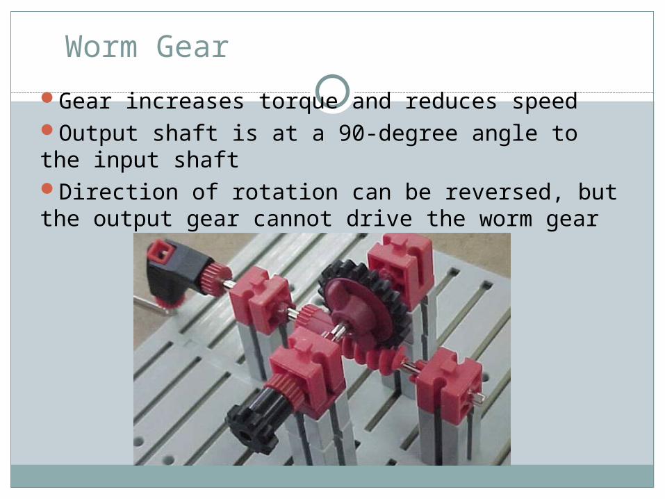
Worm Gear
Gear increases torque and reduces speedOutput shaft is at a 90-degree angle to the input shaftDirection of rotation can be reversed, but the output gear cannot drive the worm gear
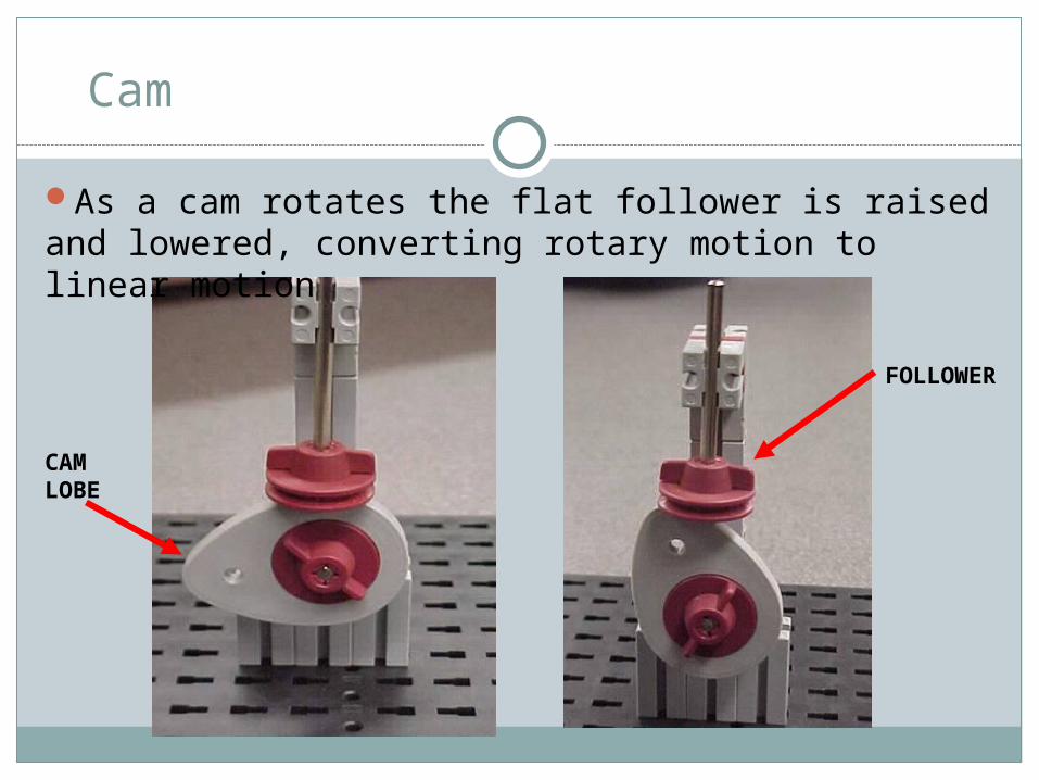
CAM LOBE
FOLLOWER
Cam
As a cam rotates the flat follower is raised and lowered, converting rotary motion to linear motion
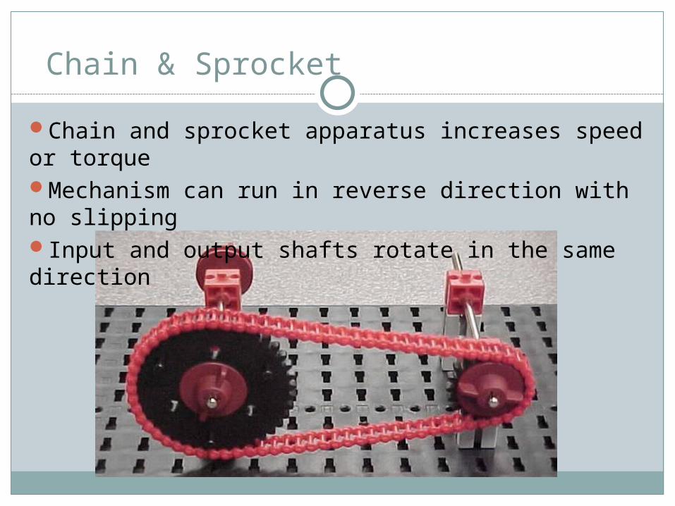
Chain & Sprocket
Chain and sprocket apparatus increases speed or torqueMechanism can run in reverse direction with no slippingInput and output shafts rotate in the same direction
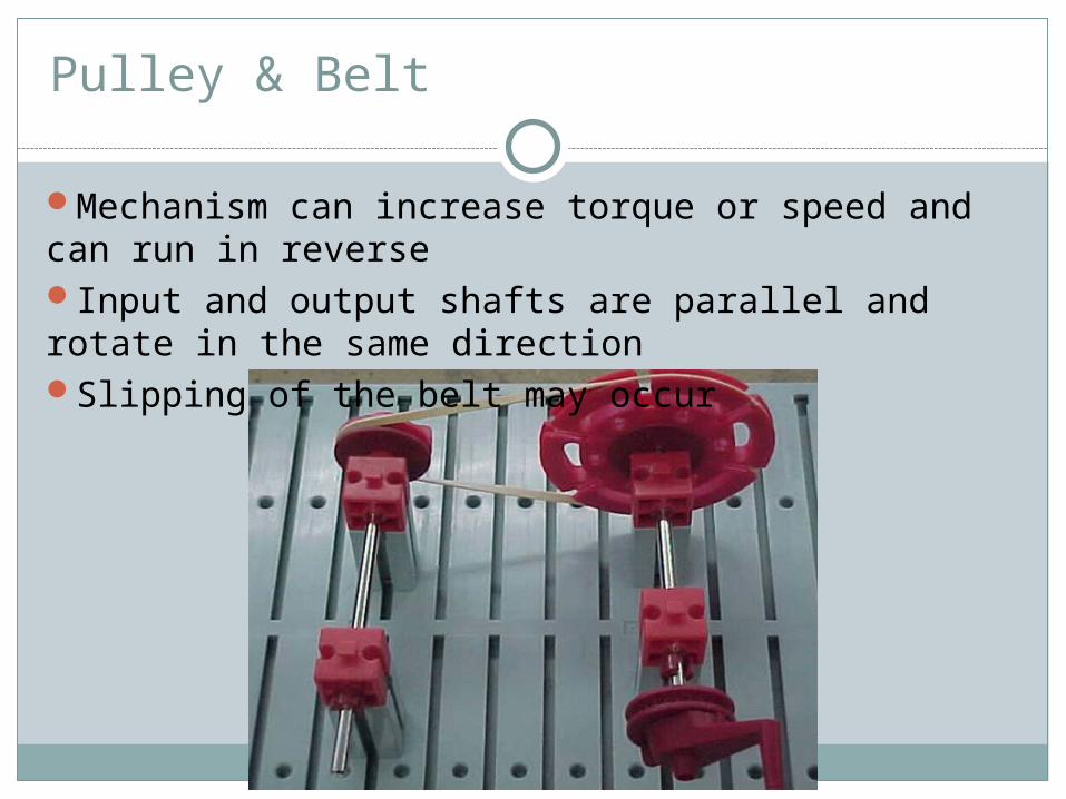
Pulley & Belt
Mechanism can increase torque or speed and can run in reverseInput and output shafts are parallel and rotate in the same directionSlipping of the belt may occur
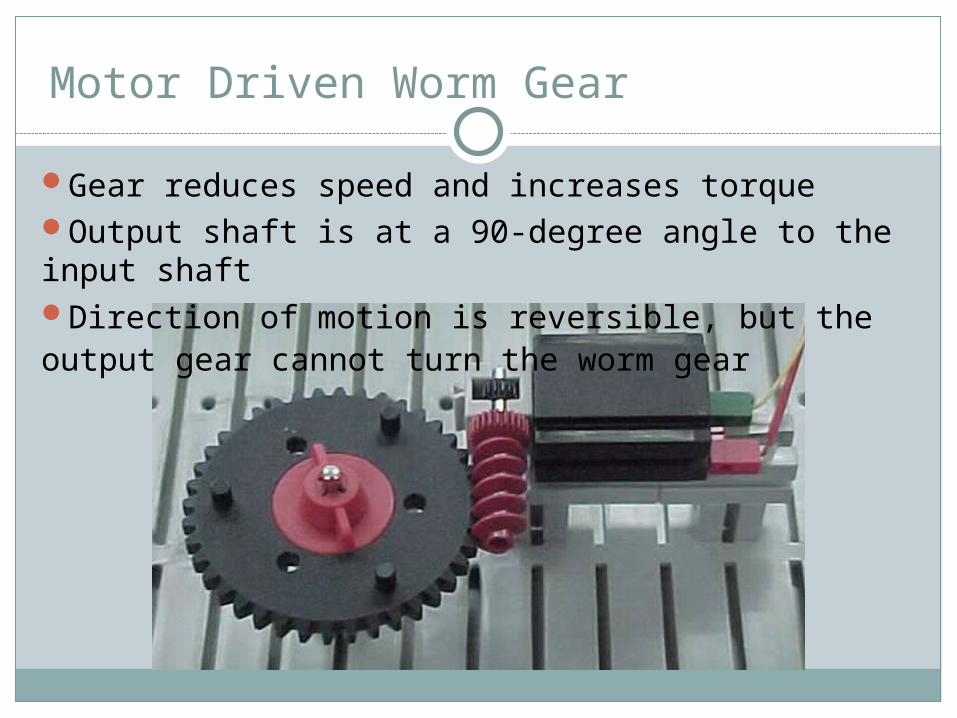
Motor Driven Worm Gear
Gear reduces speed and increases torqueOutput shaft is at a 90-degree angle to the input shaftDirection of motion is reversible, but the output gear cannot turn the worm gear
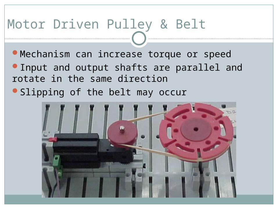
Motor Driven Pulley & Belt
Mechanism can increase torque or speedInput and output shafts are parallel and rotate in the same directionSlipping of the belt may occur
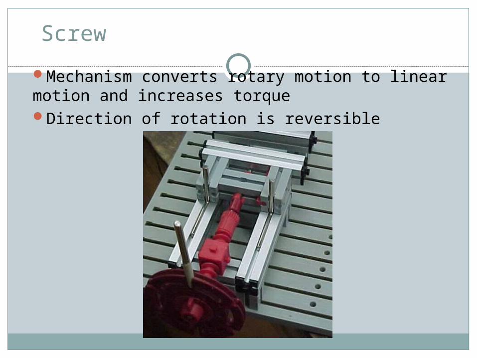
Screw
Mechanism converts rotary motion to linear motion and increases torqueDirection of rotation is reversible