continuous controller
TRANSCRIPT

Plant
��
�
D (s) G (s)r (t)u (t)
y (t)
y (t)
1
Continuous controller
e (t)
e (kT)
Sensor
��
�
r (t) Differenceequations
u (kT)
Plant
G (s) y(t)
1
Sensor
u (t)
ClockSampler
Digital controller
T
T
y(kT)
r (kT)
y(t)
(b)
(a)
D/A andhold
A/D
Figure 8.1 Block diagrams for a basic control system: (a) continuous system;(b) with a digital computer
©2002 Prentice Hall, Inc. Gene F. Franklin, J. David Powell, Abbas Emami-NaeiniFeedback Control of Dynamic Systems, 4e

u
kT1 2 3 4 5 6 7 8
u(kT )
Average u(t)
Continuous control, u(t)
Control from D/A
Figure 8.2 The delay due to the hold operation
©2002 Prentice Hall, Inc. Gene F. Franklin, J. David Powell, Abbas Emami-NaeiniFeedback Control of Dynamic Systems, 4e

f (t)
t
f (t)
f (k)
0 T 2T 3T
T
Figure 8.3 A continuous, sampled version of signal f
©2002 Prentice Hall, Inc. Gene F. Franklin, J. David Powell, Abbas Emami-NaeiniFeedback Control of Dynamic Systems, 4e

Re(z)
Im(z)
1.2
�1.0 �0.8 �0.6 �0.4 �0.2 0 0.2 0.4 0.6 0.8 1.0
1.0
0.8
0.6
0.4
0.2
0
10T9p
5T4p
10T7p
5T2p
5T3p
10T3p
10Tp
20Tp
vn �2Tp
vn �Tp z �
1.0
z � 0
s � �zvn �jvn�1 � z 2
T � sampling period
0.9
0.8
0.7
0.6
0.5
0.4
0.3
0.2 0.1
z � eTs
5T1p
Figure 8.4 Natural frequency (solid color) and damping loci (light color) in the z-plane; theportion below the Re(z)-axis (not shown) is the mirror image of the upper half shown.
©2002 Prentice Hall, Inc. Gene F. Franklin, J. David Powell, Abbas Emami-NaeiniFeedback Control of Dynamic Systems, 4e

Re(z)
Im(z)
�1 �0.5 10.5
Figure 8.5 Time sequences associated with points in the z-plane
©2002 Prentice Hall, Inc. Gene F. Franklin, J. David Powell, Abbas Emami-NaeiniFeedback Control of Dynamic Systems, 4e

e(kT)e(t)
TD (z)
u(kT)ZOH u(t) e(t) D (s) u(t)
(a) (b)
Figure 8.6 Comparison of (a) digital and (b) continuous implementation
©2002 Prentice Hall, Inc. Gene F. Franklin, J. David Powell, Abbas Emami-NaeiniFeedback Control of Dynamic Systems, 4e

t
e(t)
kT � T kT
Figure 8.7 Trapezoidal integration
©2002 Prentice Hall, Inc. Gene F. Franklin, J. David Powell, Abbas Emami-NaeiniFeedback Control of Dynamic Systems, 4e

1 21.81.61.41.20 0.2 0.4 0.6 0.8
Time (sec)
(b)
�20�10
01020304050
Con
trol
, u1 21.81.61.41.20 0.2 0.4 0.6 0.8
Time (sec)
(a)
00.20.40.60.8
11.21.4
Posi
tion,
y
Continuous controller
Continuous controller
Digital controller
Digital controller
Figure 8.8 Comparison between the digital and the continuous controller step response with asample rate 25 times bandwidth. (a) Position, (b) Control
©2002 Prentice Hall, Inc. Gene F. Franklin, J. David Powell, Abbas Emami-NaeiniFeedback Control of Dynamic Systems, 4e

��
�
R D (s)s21 YE U
Figure 8.9 Continuous-design definition for Example 8.2
©2002 Prentice Hall, Inc. Gene F. Franklin, J. David Powell, Abbas Emami-NaeiniFeedback Control of Dynamic Systems, 4e

Re(s)
Im(s)
�0.2
�0.2�2
Selected roots(Kc � 0.81)
Figure 8.10 s -plane locus with respect to K
©2002 Prentice Hall, Inc. Gene F. Franklin, J. David Powell, Abbas Emami-NaeiniFeedback Control of Dynamic Systems, 4e

r (k) u (t)u (k)
y (k)
ZOH s21
Sampler (T � 1 sec)and analog-to-digital
conversion
PlantComputer
Eq.(8.29)
y(t)
Figure 8.11 A digital control system for emulating Fig. 8.9
©2002 Prentice Hall, Inc. Gene F. Franklin, J. David Powell, Abbas Emami-NaeiniFeedback Control of Dynamic Systems, 4e

Time (sec)
0 5 10 15 20 25 30
Plan
t out
put
1.6
1.4
1.2
1.0
0.8
0.6
0.4
0.2
0
Continuous design
Emulation design
Figure 8.12 Step responses of the continuous and digital implementations
©2002 Prentice Hall, Inc. Gene F. Franklin, J. David Powell, Abbas Emami-NaeiniFeedback Control of Dynamic Systems, 4e

v (rad/sec)
T � 1/15 secvs � 100 rad/sec
T � 1/3 secvs � 20 rad/sec
�D (z)�
1
�D (z)�
1
v (rad/sec)0.5
0.10.1
MMPZTustin’s,MPZ
D (s) D (s)
MMPZ
Tustin's,
MPZ
5 50 0.5 5 50
Figure 8.13 A comparison of the frequency response of three discrete approximations
©2002 Prentice Hall, Inc. Gene F. Franklin, J. David Powell, Abbas Emami-NaeiniFeedback Control of Dynamic Systems, 4e

D (z)��
�ZOHR(s) Y(s)
(a)
D (z)��
�G (z) Y(z)R(z)
(b)
G(s)
Figure 8.14 Comparison of a (a) mixed control system and (b) its pure discrete equivalent
©2002 Prentice Hall, Inc. Gene F. Franklin, J. David Powell, Abbas Emami-NaeiniFeedback Control of Dynamic Systems, 4e

Re(s)
Im(s)
Re(z)
Im(z)
z � a
z � 0
z � �1
(a) (b)
s � �a
Figure 8.15 Root loci for (a) the z-plane and (b) the s -plane
©2002 Prentice Hall, Inc. Gene F. Franklin, J. David Powell, Abbas Emami-NaeiniFeedback Control of Dynamic Systems, 4e

Re(z)
Im(z)
�1
Figure 8.16 z-plane root locus for a 1/s2 plant with proportional feedback
©2002 Prentice Hall, Inc. Gene F. Franklin, J. David Powell, Abbas Emami-NaeiniFeedback Control of Dynamic Systems, 4e

Real axis
�1.0 �0.5 0 0.5 1.0
1.0
0.8
0.6
0.4
0.2
�0.2
�0.4
�0.6
�0.8
�1.0
Imag
axi
s
Desiredroot
Desiredroot
Figure 8.17 z-plane locus for the 1/s2 plant with D(z) = K(z − 0.85)/z
©2002 Prentice Hall, Inc. Gene F. Franklin, J. David Powell, Abbas Emami-NaeiniFeedback Control of Dynamic Systems, 4e

Time (sec)
0 5 10 15 20 25 30
Plan
t out
put
1.6
1.4
1.2
1.0
0.8
0.6
0.4
0.2
0
Continuous design
Emulation design
Discrete design
Figure 8.18 Step response of the continuous and digital systems in Examples 8.2 and 8.4
©2002 Prentice Hall, Inc. Gene F. Franklin, J. David Powell, Abbas Emami-NaeiniFeedback Control of Dynamic Systems, 4e

Time (sec)
0 5 10 15 20 25 30
Plan
t out
put,
y(t)
1.6
1.4
1.2
1.0
0.8
0.6
0.4
0.2
0
Command structure from Fig. 7.46(b)
Command structure from Fig. 7.10
Figure 8.19 Step response of Example 8.7
©2002 Prentice Hall, Inc. Gene F. Franklin, J. David Powell, Abbas Emami-NaeiniFeedback Control of Dynamic Systems, 4e

Time (sec)0.02 0.08 0.1
50-Hz samples
Aliased signalfrom samples
60-Hz signal
Figure 8.20 An example of aliasing
©2002 Prentice Hall, Inc. Gene F. Franklin, J. David Powell, Abbas Emami-NaeiniFeedback Control of Dynamic Systems, 4e

�
�
�
U
z � 0.26 X1
z � 0.35
E
X2
Figure 8.21 An example of parallel implementation
©2002 Prentice Hall, Inc. Gene F. Franklin, J. David Powell, Abbas Emami-NaeiniFeedback Control of Dynamic Systems, 4e
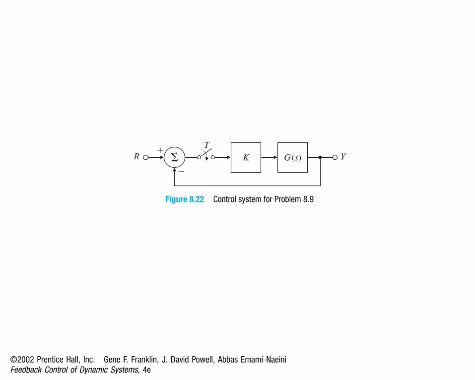
��
�
G (s) YKRT
Figure 8.22 Control system for Problem 8.9
©2002 Prentice Hall, Inc. Gene F. Franklin, J. David Powell, Abbas Emami-NaeiniFeedback Control of Dynamic Systems, 4e

u
Inertialreference
Figure 8.23 Satellite control schematic for Problem 8.14
©2002 Prentice Hall, Inc. Gene F. Franklin, J. David Powell, Abbas Emami-NaeiniFeedback Control of Dynamic Systems, 4e
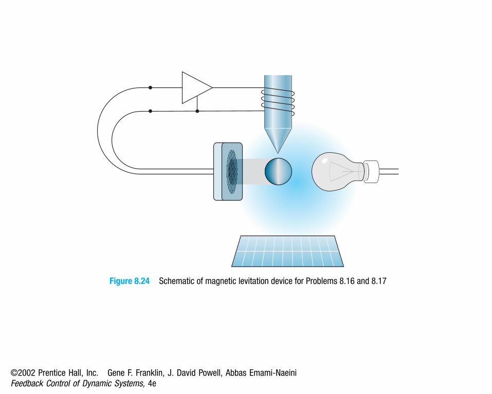
Figure 8.24 Schematic of magnetic levitation device for Problems 8.16 and 8.17
©2002 Prentice Hall, Inc. Gene F. Franklin, J. David Powell, Abbas Emami-NaeiniFeedback Control of Dynamic Systems, 4e

Figure 8.25 Satellite-tracking antenna (Courtesy Space Systems/Loral)
©2002 Prentice Hall, Inc. Gene F. Franklin, J. David Powell, Abbas Emami-NaeiniFeedback Control of Dynamic Systems, 4e
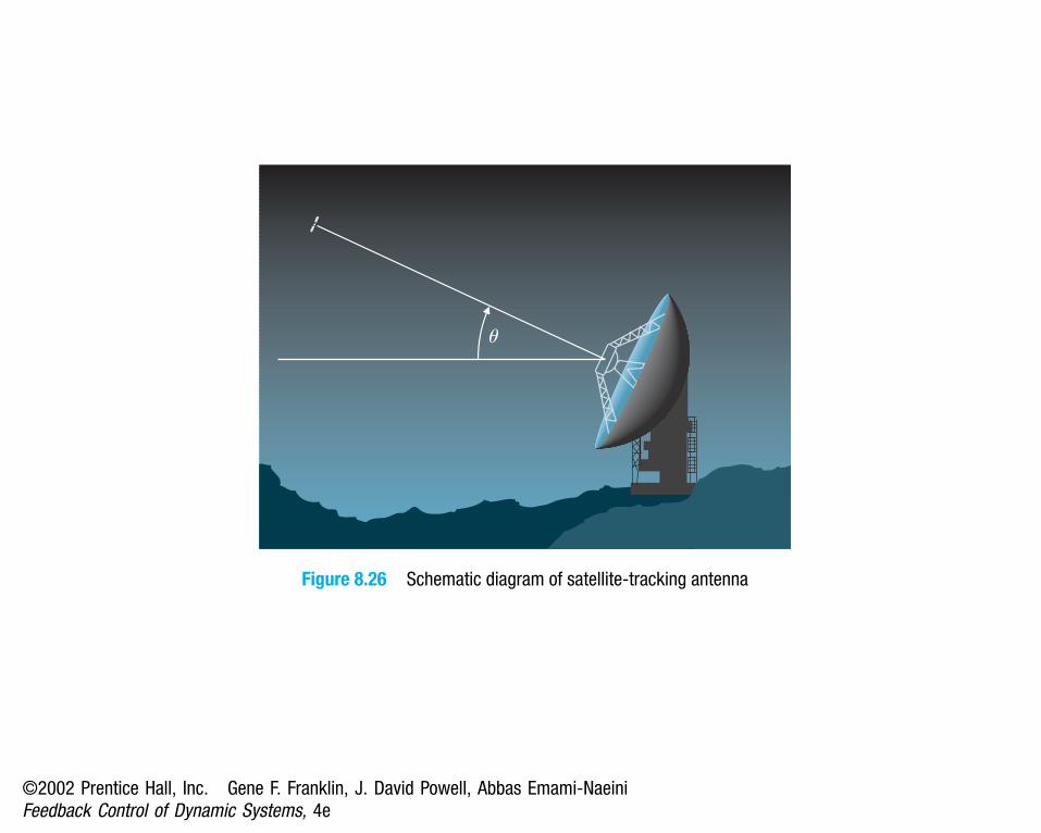
u
Figure 8.26 Schematic diagram of satellite-tracking antenna
©2002 Prentice Hall, Inc. Gene F. Franklin, J. David Powell, Abbas Emami-NaeiniFeedback Control of Dynamic Systems, 4e

Negligible heatloss in walls
Hot
Cold
Tank fluid attemperature Te
Te
Tei
Tec
Mixingvalve
Figure 8.27 Tank temperature control
©2002 Prentice Hall, Inc. Gene F. Franklin, J. David Powell, Abbas Emami-NaeiniFeedback Control of Dynamic Systems, 4e

��
�
YRE
s(s � 1)1
K (1 � TDs � TIs1 ) U
Figure 8.28 Control system for Problem 8.21
©2002 Prentice Hall, Inc. Gene F. Franklin, J. David Powell, Abbas Emami-NaeiniFeedback Control of Dynamic Systems, 4e