control adjustment and operation instructions
TRANSCRIPT

er/technician. Read and follow this manual, all supplements and related instructional information provided with the boiler. Install, start and service the boiler only in the sequence and methods given in these instructions. Failure to do so can result in severe personal injury, death or substantial property damage.
Do not use the boiler during construction. Construction dust and particulate, particularly drywall dust, will cause contamination of the burner, resulting in possible severe personal injur e boiler can only be operated with a dust-free air supply. Follow the instruction manual procedures to duct air to the boiler air intake. If the boiler has been contaminated by operation with contaminated air, follow the instruction manual guidelines to clean, repair or replace the boiler if necessary.
x these instructions near to the boiler/water heater. Instruct the building owner to retain the instructions for future use bservice technician, and to follow all guidelines in the User’s Information Manual.
KNV3-0714
Cast Iron Condensing BoilersModels K N-6, KN-10, KN-16, KN-20, KN-26 and KN-30
V3
Also read and follow:
KN-Series Gas Boiler Installation and Operating Instructions
This instruction manual applies only to Advanced Thermal Hydronics firmware version 1.x on version 3.x control boards. Current firmware is backwards compatible with version 1.x & 2.x boards, but some current features may not be available. To replace firmware on an existing boiler, contact the factory to obtain the original firmware file or for assistance in applying current firmware to an older versioncontrol board.
Control adjustment and operation instructionsfor Advanced Thermal Hydronics firmware version 1.08

TABLE OF CONTENTS HeatNet Control V3 2.x
Page 2
TABLE OF CONTENTS
TABLE OF CONTENTS .............................................................................................................................. 2
Introduction ............................................................................................................................................... 4 THE KN-SERIES V3 HEATNET CONTROL .............................................................................................................................................. 4
Features & Specifications ......................................................................................................................... 6 STANDARD FEATURES OVERVIEW ........................................................................................................................................................ 6
Specifications ............................................................................................................................................ 8
Components & Accessories ..................................................................................................................... 9 PART NUMBER COMPONENT ........................................................................................................................................................... 9
SETUP & OPERATION ............................................................................................................................. 10 BASIC MULTI BOILER SYSTEM OPERATION .......................................................................................................................................... 10
MIXED BOILER TYPES USING PRIORITY SETS ...................................................................................................................................... 11
MIXED BOILER SYSTEM OPERATION ................................................................................................................................................... 11
START/STOP PRIORITY CONDITIONS .................................................................................................................................................. 13
SELECTING MIXED BOILERS .............................................................................................................................................................. 14
MIXED SYSTEM TYPE 1: HIGH SYSTEM TURNDOWN ............................................................................................................................ 14
MIXED SYSTEM TYPE 2: CONDENSING / NON-CONDENSING .................................................................................................................. 18
BASE LOADING, RELAY CONTROL ...................................................................................................................................................... 21
SETTING UP BASE LOADING ................................................................................................................................................................ 23
Heating Control Methods ........................................................................................................................ 24 HEATING METHOD 1 ......................................................................................................................................................................... 24
HEATING METHOD 2 ......................................................................................................................................................................... 24
HEATING METHOD 3 ......................................................................................................................................................................... 24
HEATING METHOD 4 ......................................................................................................................................................................... 24
HEATING METHOD 5 ......................................................................................................................................................................... 24
OPERATING LIMIT ............................................................................................................................................................................. 24
INPUT PRIORITIES ............................................................................................................................................................................. 24
HEATING METHOD 1 HEAT DEMAND ............................................................................................................................................... 25
HEATING METHOD 2 STAGE CONTROL T1-T2 ................................................................................................................................... 26
HEATING METHOD 3 4-20MA CONTROL .............................................................................................................................................. 26
HEATING METHOD 4 AA INPUT .......................................................................................................................................................... 26
HEATING METHOD 5 MODBUS COMMUNICATIONS .............................................................................................................................. 27
Using the 4-20ma input (OPTIONAL) ...................................................................................................... 28 SETPOINT PRIORITIES ....................................................................................................................................................................... 29
Circulator Pump Options ........................................................................................................................ 30
Auxiliary Function Options ..................................................................................................................... 32
Outdoor Reset ......................................................................................................................................... 32
Sensors .................................................................................................................................................... 33
Stack Temperature .................................................................................................................................. 33

TABLE OF CONTENTS HeatNet Control V3 2.x
Page 3
Security .................................................................................................................................................... 33
Saving Configuration Settings ................................................................................................................ 33
USB Features ........................................................................................................................................... 33
Diagnostics .............................................................................................................................................. 34
Blower Protection .................................................................................................................................... 34
Communications ...................................................................................................................................... 35
Failsafe Modes ......................................................................................................................................... 35 FAILSAFE REQUIREMENTS: ....................................................................................................................................................... 35
Flow Options ............................................................................................................................................ 36
HeatNet Online ......................................................................................................................................... 37
Domestic Hot Water Methods ................................................................................................................. 39 DHW METHOD 1: DHW HEATING ONLY USING A DHW MASTER AND MEMBER BOILER(S) EMPLOYING H-NET. ................................... 39
DHW METHOD 2: COMBINATION DHW AND SPACE HEATING USING A MASTER BOILER AND MEMBER BOILER(S) ................................. 41
(MASTER TYPE: MIXED) .................................................................................................................................................................. 41
DHW METHOD 3: DHW HEATING USING A HEADER SENSOR INPUT ................................................................................................... 43
DHW METHOD 4: SPACE HEATING WITH DHW OVERRIDE OF SETPOINT ON MASTER.......................................................................... 44
DHW METHOD 5: DHW OF A LOCAL BOILER’S TANK. ....................................................................................................................... 44
DHW METHOD 6: DHW USING DIRECT CONTROL ............................................................................................................................ 47
Wiring Connections ................................................................................................................................. 48
Calibration ................................................................................................................................................ 59
Log Entry .................................................................................................................................................. 60
Default Settings & Menu Item Descriptions — SETUP .......................................................................... 61
Default Settings & Menu Item Descriptions — ADVANCED SETUP ..................................................... 67
MODBUS Communications ..................................................................................................................... 74
Troubleshooting ...................................................................................................................................... 85
KN HeatNet Control Run Screen ............................................................................................................. 90
KN HeatNet Control Run Screen - Continued ........................................................................................ 91
KN HeatNet V3 Menu Tree — ADVANCED THERMAL HYDRONICS ..................................................... 92
KN HeatNet V3 Advanced Menu Tree – ATH .......................................................................................... 93
Worksheet ................................................................................................................................................ 94
Type II Thermistor Resistance/Temperature Table................................................................................ 99
* Status Information ............................................................................................................................... 100 STATUS INFORMATION SCREENS ...................................................................................................................................................... 100
Status Screen Fault Display .................................................................................................................. 102
Line 4 Log Entries: ................................................................................................................................ 105
Information contained in this publication regarding device applications and the like is provided only for your convenience and may be superseded by updates. It is your responsibility to ensure that your application meets with
your specifications.
Advanced Thermal Hydronics MAKES NO REPRESENTATIONS OR WARRANTIES OF ANY KIND WHETHER EXPRESS OR IMPLIED,
WRITTEN OR ORAL, STATUTORY OR OTHERWISE, RELATED TO THE INFORMATION, INCLUDING BUT NOT LIMITED TO ITS CONDITION, QUALITY, PERFORMANCE, MERCHANTABILITY OR FITNESS FOR
PURPOSE.
http://www.knseries.com/
The Advanced Thermal Hydronics name and logo, Mestek name and logo, KN, HeatNet, and H-Net name and logo are registered
trademarks of Mestek, Incorporated in the U.S.A. and other countries.
BACnet is a registered trademark of ASHRAE. LonWorks is a registered trademark of Echelon Corporation. All trademarks mentioned herein are property of their respective companies.
© 2012, Mestek Technology Incorporated, Printed in the U.S.A., All Rights Reserved.
.

FEATURES & SPECIFICATIONS HeatNet Control V3 2.x
Page 4
Introduction
The KN-Series V3 HeatNet Control
The KN-Series V3 boiler control is the third generation of
the HeatNet control platform. Control hardware has been
added to make use of many new heating applications. These
new features are outlined in the Features & Specifications
section.
The KN-Series boiler control is designed to provide the KN-
Series of boilers with an integrated boiler management
system on every boiler. Designed for the Air-Fuel coupled
KN-Series boilers, the KN-Series HeatNet control provides
for optimized heating efficiency without the need for a ―wall
mount control‖. Since the KN-Series modular control
method is based on digital communications, analog control
signals are not required. Although the use of analog control
signals is still supported (4-20mA control loops and 0-10vdc
control voltages), a higher level of control precision,
repeatability, and feedback is gained with digital
communications control.
With the KN-Series, optimized heating efficiency is
accomplished by setting the Modulation Maximum (Mod-
Max) setting to exploit the inverse efficiency curve. This
value can be adjusted so that as each boiler is added, it
operates at its maximum turndown. This allows the
maximum number of boilers to operate at their lowest
inputs, until all boilers are firing. Once all boilers are firing,
full range modulation control is allowed. An outdoor reset
function is also provided to assist in the optimized heating
efficiency of the KN-Series boilers.
The KN-Series boiler with the KN-Series H-Net control, can
be operated in multiple ways:
1. As a stand-alone boiler.
2. A boiler in a Boiler Network using the HeatNet®
(H-Net®) protocol.
3. A member boiler to a boiler management system with
multiple input control methods.
The primary purpose of the control is to maintain the boiler
water temperature at the supply or the header sensor using a
target setpoint. While performing this task, the control also
monitors dedicated external limits in a limit string and
provides an orderly shutdown and fault indication in the
event of a tripped limit. The monitored limits include a
HIGH LIMIT AQUASTAT, LOW WATER CUTOFF,
GAS PRESSURE, FLOW, IGNITION CONTROL fault,
GAS VALVE alarm, VARIABLE FREQUENCY DRIVE
alarm, and other optional or user selectable limits.
The HIGH LIMIT circuit is independent of the control and shuts down the ignition control and the boiler if the control board or other component of the boiler was to malfunction. The control will continue to function and report the fault, but its ability to control the boiler will end.
Each KN-Series boiler employing this control can function
as either a master or a member. This allows one boiler
(Master) to be in control of target temperature. The other
boilers (Members) only respond to the commands issued by
the Master. If using an external control, all boilers can be
setup as members. The following will define the roles of
master and member.
Master
A boiler becomes a master when a temperature sensor is
connected to the J10 ―SYSTEM HEADER‖ terminals. The
sensor is auto-detected.
The master senses and controls the common system
header/loop water temperature using a system setpoint. It
uses any boilers it finds (over the H-Net communications
cable) to accomplish this. It can also monitor the Outside
Air (OA) temperature to provide outdoor reset functionality.
Only one master is allowed in a system.
When operating as a master, the boiler provides a control
method using a PID algorithm to regulate water
temperature. This algorithm allows a single boiler (Master),
or multiple (Master + Member) boilers.
Figure 1 Heat band
SETPOINT
UPPER HEAT
BAND LIMIT
LOWER HEAT
BAND LIMITBoilers Staged
ON
BOILERS
STAGED
OFF
Time
WATER
TEMPERATURE
The control algorithm is based upon a Heat Band, at the
center of which is the setpoint. While below the Heat Band,
boilers are staged on and modulated up until the Heat Band
is entered. Once in the Heat Band, modulation is used to
maintain setpoint. Boilers are shut down only when the top
of the Heat Band is breached. Timers are also used to
prevent short cycling.
While staging the boilers on, a modulation clamp
ADVANCED SETUP: MODULAR BOILER SET:
MOD MAX-LAST FIRE is used to hold the boilers at a
lower fire rate until the last boiler is fired. Once the last
boiler fires, the modulation clamp is removed and all boilers
are allowed to fire above this clamped percentage up to
FEATURES & SPECIFICATIONS HeatNet Control V3 2.x
Page 5
100%. This ―boiler efficiency‖ clamp is defaulted to 70%
and thus limits all of the boilers individual outputs to 70%
until the last boiler fires. All running boilers modulate up
and down together, always at the same modulation rate. As
a general rule, this percentage should be no lower than twice
the minimum turndown to minimize short cycling.
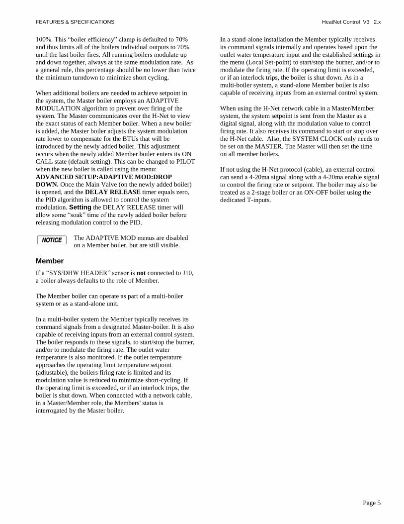
When additional boilers are needed to achieve setpoint in
the system, the Master boiler employs an ADAPTIVE
MODULATION algorithm to prevent over firing of the
system. The Master communicates over the H-Net to view
the exact status of each Member boiler. When a new boiler
is added, the Master boiler adjusts the system modulation
rate lower to compensate for the BTUs that will be
introduced by the newly added boiler. This adjustment
occurs when the newly added Member boiler enters its ON
CALL state (default setting). This can be changed to PILOT
when the new boiler is called using the menu:
ADVANCED SETUP:ADAPTIVE MOD:DROP
DOWN. Once the Main Valve (on the newly added boiler)
is opened, and the DELAY RELEASE timer equals zero,
the PID algorithm is allowed to control the system
modulation. Setting the DELAY RELEASE timer will
allow some ―soak‖ time of the newly added boiler before
releasing modulation control to the PID.
The ADAPTIVE MOD menus are disabled on a Member boiler, but are still visible.
Member
If a ―SYS/DHW HEADER‖ sensor is not connected to J10,
a boiler always defaults to the role of Member.
The Member boiler can operate as part of a multi-boiler
system or as a stand-alone unit.
In a multi-boiler system the Member typically receives its
command signals from a designated Master-boiler. It is also
capable of receiving inputs from an external control system.
The boiler responds to these signals, to start/stop the burner,
and/or to modulate the firing rate. The outlet water
temperature is also monitored. If the outlet temperature
approaches the operating limit temperature setpoint
(adjustable), the boilers firing rate is limited and its
modulation value is reduced to minimize short-cycling. If
the operating limit is exceeded, or if an interlock trips, the
boiler is shut down. When connected with a network cable,
in a Master/Member role, the Members' status is
interrogated by the Master boiler.
In a stand-alone installation the Member typically receives
its command signals internally and operates based upon the
outlet water temperature input and the established settings in
the menu (Local Set-point) to start/stop the burner, and/or to
modulate the firing rate. If the operating limit is exceeded,
or if an interlock trips, the boiler is shut down. As in a
multi-boiler system, a stand-alone Member boiler is also
capable of receiving inputs from an external control system.
When using the H-Net network cable in a Master/Member
system, the system setpoint is sent from the Master as a
digital signal, along with the modulation value to control
firing rate. It also receives its command to start or stop over
the H-Net cable. Also, the SYSTEM CLOCK only needs to
be set on the MASTER. The Master will then set the time
on all member boilers.
If not using the H-Net protocol (cable), an external control
can send a 4-20ma signal along with a 4-20ma enable signal
to control the firing rate or setpoint. The boiler may also be
treated as a 2-stage boiler or an ON-OFF boiler using the
dedicated T-inputs.

FEATURES & SPECIFICATIONS HeatNet Control V3 2.x
Page 6
Features & Specifications
HeatNet Version 3.x Discontinued Features from Version 2.x Control
1. With this hardware release the service power, switched power, and the power switch connector have been removed. These were available on prior versions of the HeatNet control. Upgrading to this control from prior versions will require some wiring changes using an upgrade kit.
2. The J10B input is no longer supported for proving the damper. Damper proving switches will need to be wired to J12B. J10B wires from the prove switch should now be connected to J12B.
3. If a stack sensor is used with this version, the alarm silence switch can not be connected and the disconnected wires should be terminated appropriately.
Silencing the alarm can be done by holding the BACK and SELECT keys down at the same time.
Hardware Version 3.x Control Additional Features (Identified by circuit board color: BLACK)
1. Support for (2) Circulator pumps. Two rotation modes
are provided: Based on system runtime or system pump
runtime hours. Pump failure switchover/retry mode.
2. Warm weather shutdown, (2) pump jog and local pump
jog to keep pumps from seizing.
3. The Modbus, BACnet or LonWorks communications
port can be accessed concurrently with the USB port
(HeatNet Control Pro). The BACnet, LonWorks, or
Modbus connections do not need to be disabled to use
the USB ports.
4. The DHW pump and the Local Pump relay connections
now provide a normally closed contact. This allows for
the use of a power open/power close valve.
5. Support for 5ma 0-10v control signals using third party
controls.
6. Support for (2) display types: Vacuum Florescent and
Color LCD using the same 20 pin ribbon cable.
7. System Return sensor input.
8. Enhanced bootloader and firmware storage. One
firmware storage location for user updates. One
firmware program that always remains resident so that a
factory program can be restored. Primary loading is
with a flashdrive.
9. Support for High Efficiency Ametek blowers.
10. 32 bit Microcontroller operating @64Mhz with 5-stage
pipeline, and prefetch cache.
11. (3) stage control relay outputs for TBD applications.
12. Backwards compatible with existing HeatNet versions
1.x and 2.x controls and applications.
13. Support for 135 Ohm control actuators.
14. 1k Platinum Stack sensor
15. Flow meter input or BMS GPM input/control
16. On-board HeatNet Online network module.
17. Dual PID controls. One for space heating and one for
DHW heating. Allows for simultaneous DHW/Space
heating.
Standard Features Overview
1. Five levels of external control inputs, including
modulation and staging that provide application
flexibility.
2. Digital Communications Control (analog 4-20ma and 0-
10vdc control supported, but not required).
a. Boiler to Boiler : HeatNet (H-Net)
b. Building Management System (MODBUS,
Optional BACnet or LonWorks) to Boiler
3. Distributed control using the HeatNet (H-Net) protocol
for up to 16 boilers. Eliminates the need for ―wall
mounted‖ controls.
4. Analog Control 4-20ma and 0-10vdc (5mA minimum
current) signals supported.
5. System/Boiler operating status text display
6. Interlock, Event, and System logging with a time
stamp.
7. Advanced PID algorithm optimized for the KN-Series
boilers.
8. (4) Dedicated temperature sensor inputs for: Outside
Air Temperature, Supply (Boiler Outlet) Temperature,
Return (Boiler Inlet) Temperature, and Header
(Common System Supply) Temperature.
9. Automatically detects the optional temperature sensors
on power up.

FEATURES & SPECIFICATIONS HeatNet Control V3 2.x
Page 7
10. Menu driven calibration and setup menus with a bright
(Adj.) 4 line Vacuum Fluorescent Display.
11. (8) Dedicated 24vac interlock monitors, and 8 dedicated
120vac system monitors used for diagnostics and
providing feedback of faults and system status.
12. Multiple circulator pump control modes.
13. Combustion Air Damper control with proof time,
support for a common combustion air damper.
14. USB/RS485 network plug-in to allow firmware updates
or custom configurations.
15. Optional BACnet or LonWorks interface.
16. Alarm Relay dry contacts, and Audible Alarm.
17. Runtime hours, and Cycles (based on Main Valve
Open).
18. Outdoor Air Reset with programmable setpoint and
ratio.
19. Time of Day clock to provide up to (4) night setback
temperatures.
20. Failsafe mode when a Building Management System is
controlling setpoint. If communications is lost, the
boiler/system automatically transfers to local boiler
setpoint control.
21. Rotation Methods(Lead-Lag): True Rotation (based on
boiler runtime)is default. First On First Off (FOFO),
Last On First Off (LOFO) and MIXED are optional.
22. Programmable password protection to secure the
programmable settings.
23. Remote 4-20mA setpoint control using a mapped
setpoint range to the 4-20mA control signal.
24. Freeze Protection allowing automatic starting of
boiler(s) using (2) Failsafe modes.
25. Adaptive Modulation. When additional boilers are
called, the Master adjusts all boilers fire rates to
compensate.
26. Mixed boiler types in a system.
27. Support for Domestic Hot Water (DHW) using a 10k
Sensor or a dry contact input from a tank thermostat.
28. Domestic Hot Water relay for use with a pump or
valve.
29. On-board power and socket for Protocessor
BACnet/LonWorks module.
30. HI/LO relay control option from connector J4
31. Resettable Fused interlock power circuit.
32. Additional terminal connector for H-Net shielded cable.
33. Backwards compatible to Version 1.x hardware.
34. Communications board integrated with the main board
from version 1.x control.
35. Base Loading of (1) boiler.
36. Delayed Blower Power staging. Used to minimize
inrush currents by powering the blower 7 seconds after
main power.

FEATURES & SPECIFICATIONS HeatNet Control V3 2.x
Page 8
Specifications
Control Microprocessor based PID modulating control ( NOT a safety limit )
Environment -40 °F to 140 °F, <90% RH non-condensing
Input Power 24 VAC, 500 ma
Relays System Pump, Damper, Circulator, Alarm, DHW Pump (v2.x), 8A 250 VAC resistive
K8 on J4.2 &.6 for Base Loading version 2.x Control
AC Interlocks 24 VAC – 120 VAC input
Control Inputs AA, Heat Demand, 4-20ma Enable, OA override, T1-T2 (dry contact inputs)
4-20mA, 0-10 VDC
Dimensions 9‖ wide: 6‖ high : 2‖ deep
Temperature Sensors NTC thermistor, 10K @ 77 °F, 335.67K @ -40 °F, 185 @ 150 °F ,+/- 1 F
USB 1.0
RS485 MODBUS Modbus RTU
Boiler-to-Boiler HeatNet (H-Net)
Network Optional LonWorks, BACnet available bridge to MODBUS port

Page 9
Components & Accessories
Part Number Component
02-4297 KN-Series Control Board Version 3.x
02-4278 Graphics Display Board
Color Touch Panel Display
02-3926 ACI/10K-CP-BP Temperature probe (bullet type, 1x.250 inch)
02-4283 ACI 10k-CP-I-NW Supply, Header, Return Sensors
02-4285 ACI CP-I-2.5‖ Sensor with well
02-4286 ACI CP-I-4‖ Sensor with well
02-4281 ACI 10k-CP-S Strap-on sensor
ACI X/(2) CP-PO -4 4‖ probe with dual sensor
ACI X/(2) CP-PO -6 6‖ probe with dual sensor
02-4280 ACI 10k-CP-O Outside Air Sensor with Housing
0040-1300 1k Platinum Stack sensor
Installation & Operation Manual
40-5409 RJ45 Communications Cable Assembly, 25 feet
40-5411 Ribbon Cable Assembly (Display Control)
58-1833 10k ohm Calibration Resistor
40-5408 USB Cable Assembly, 6ft
60-5631 Terminal Block Screwdriver
Contact Factory MODBUS to BACnet bridge
Contact Factory MODBUS to LonWorks bridge
Contact Factory MODBUS to HeatNet Online bridge

SETUP & OPERATION HeatNet Control V3 2.x
Page 10
SETUP & OPERATION
Basic Multi Boiler System Operation
For boiler system setup/installations please refer to Refer to the 2008 ASHRAE Handbook, CH12 or later revision.
A basic multi boiler system typically uses boilers of the
same size and type. With HeatNet, this includes (1) Master
and (1-15) Member boilers. The boilers are connected
together using an H-Net communications cable effectively
creating (1) boiler. This allows the system heating BTUs to
be evenly distributed amongst all of the boilers. (See: Figure
35, Typical Single Boiler System, page 55).
Figure 2 Basic multiple boiler system
A basic multi boiler system can be configured using the
boiler menus to create custom systems/features. These
features are best described in the section: Default Settings & Menu Item Description, page 61. Along with these menu items are hardware support for many auxiliary functions.
Once the system has been properly setup (all default menu
values used and H-Net addresses assigned), the system is
enabled by placing the REMOTE/LOCAL switch to the
LOCAL position on the Master boiler. All Member boilers
must have their respective switches in the REMOTE
position. When the Master boiler‘s Heat Demand input
(LOCAL switch) closes, the system becomes operational
and will fire as many boilers as it needs to maintain the
header water temperature‘s setpoint. See the DHW section
to fire to two setpoints.
When a boiler is to be fired in a multi boiler system (header
water temperature is below the heating band), the Master
checks the HeatNet boilers it has available. Then the Master
checks if a Lead Boiler is to be used (LEAD BOILER > 0).
The Master boiler then looks at which type of firing rotation
it has selected: LOFO, FOFO, TRUE (runtime), or MIXED.
In our example we will use the TRUE (runtime) rotation
since it is the default.
The Master now checks all of the runtimes to determine
which boiler has the least runtime based on the MIN
RUNTIME setting in ADVANCED SETUP:FIRING
MODE:. The MIN RUNTIME setting is the minimum
runtime interval in hours that is used to compare boiler to
boiler runtimes.
Once the boiler to fire has been determined, the Master
sends the command over the H-Net cable to fire that boiler
and resets the ADD BOILER delay timer to prepare for the
next boiler to fire. If the header water temperature is still
below the heating band and the ADD BOILER delay timer
has expired to zero, the process is repeated until the header
water temperature enters the heating band.
When a boiler receives a command to fire:
1. The system pump relay is enabled and the H-Net control displays 'Flow Wait' until the flow-switch closes between J11A, 1 & 2 within the programmed time (10seconds).
2. All elements in the interlock string, terminated between J11A and J11B, must be closed before the sequence is allowed to continue.
3. If all interlocks are closed relay K5 is enabled to command the combustion-air damper open (If used). The H-Net control displays 'Damp: Wait' until the damper end switch closes.
4. Relay K6 is enabled energizing the local pump (if used). The H-Net control commences its 'Flow-Wait' timer (adjustable 10–240 sec.). The flow switch contact is checked on terminals J11B, 5 &6.
5. With all the interlocks closed, the boiler start relay K1 is enabled and energizes terminal 6 on the ignition control. This signal is present on J5 Boiler Start Operator.
6. The ignition control begins its cycle and provides an output signal from terminal 4 to the H-Net control J5 Blower. The H-Net control responds and provides an output signal to the VFD which sets the blower to the programmed pre-purge speed. If an Ametek blower is used, a soft start speed is applied before the pre-purge speed.
7. After air-flow is established the ignition control waits for the air switch to close. When the air switch closes it provides an input to terminal 7 and pre-purge timing commences. The H-Net display indicates 'Pre Purge'.
8. When purge is complete the ignition control energizes the pilot gas valve from terminal 8, and the spark generator from terminal 10, beginning a 10-second Pilot Flame Establishing Period (PFEP). The H-Net control responds to J5 Pilot Valve and provides an output signal to the VFD which sets the blower to the programmed ignition speed. The H-Net display indicates 'Pilot'.
9. At the end of the PFEP the spark generator is de-energized. If the pilot flame is detected, by the UV scanner, the ignition control energizes the main gas

SETUP & OPERATION HeatNet Control V3 2.x
Page 11
valve from terminal 9 to J5 Main Valve. The H-Net display indicates 'Run'.
10. If main-flame is detected the H-Net control holds the burner at the low-fire rate for the MODULATION DELAY time period. After this timer expires, the PID allows the boiler to modulate and places the boiler into the running state.
As boilers are added to the system settings in the ADVANCED SETUP:ADAPTIVE MOD:DROP DOWN menu determines
when the modulation rate drops down to compensate for the
newly added BTUs. For the drop down to be active, one
boiler needs to be running when a new boiler is added (see:
Introduction: The KN-SERIES H-Net Control: Master).
If all boilers are firing, the modulation rate is released to go
to 100%. If all boilers are not firing, the modulation is
limited to the MOD-MAX clamp value. The MOD-MAX
clamp is used to keep the boilers running as efficiently as
possible. The following Mixed Boiler System Operation:
Selecting Mixed Boilers section outlines this with examples.
NOTE: If the boiler is running as a stand-alone boiler or
is direct modulated (including the AA input),
the MOD-MAX clamp will also be in effect
for the ADD BOILER DELAY time. This is to
minimize thermal shock to the boiler.
Once the header water temperature is in the heating band,
only the modulation rate is used to achieve the target
setpoint. The system will maintain the setpoint until the load
demand increases or decreases.
As the load decreases, the header water temperature will
start approaching the top of the band. The PID now lowers
the modulation rate to the boilers, attempting to keep the
temperature within the heating band. If the system is
delivering too many BTUs, the water temperature will cross
the top of the heating band.
When the header water temperature first exceeds the top of
the heating band, the boilers are again checked for the one
with the most runtime. The selected boiler will turn off
immediately and a shed boiler delay timer will be loaded
with the delay time. This time will need to expire before the
next boiler will be stopped, but only if the header water
temperature remains above the heating band. This timer is
used to allow the header water temperature to return back
into the band when a boiler is stopped. When a boiler is
stopped there is a fixed rate of BTUs (Min Fire) that will be
removed (PID discontinuity to modulate from Min Fire to 0
BTUs on a boiler). The timer allows for this loss of BTUs.
This cycle will continue until the call for heat is satisfied or
the Warm Weather Shutdown feature is enabled.
Mixed Boiler Types Using Priority Sets
Using the Basic Multi Boiler System Operation, a MIXED
boiler Priority method may be added to control condensing,
non-condensing, base load, or other boiler SETs in a system
together. These sets compose a system which provides for
optimal performance and economy. Having dedicated sets
of boilers gives the system engineer a tool to create many
different boiler systems.
A boiler set can be constructed by simply setting the firing
Priority on each boiler (to be in a set) at the same priority.
Setting all (example) condensing boilers to the highest
Priority of 1, and then setting all (example) non-condensing
boilers to a Priority of 2, will create (2) sets of boilers, one
condensing and the other non-condensing. Once this is
done, the Priority 1 set of condensing boilers will have a
firing order that has a higher Priority and is independent of
the other non-condensing set with the lower priority. The
boiler set with the highest Priority can then be fired based
on a conditional settings menu. The lower Priority set will
follow.
Mixed Boiler System Operation
Starting Boilers:
When a boiler is to be fired (water temp is below the heating
band), the Master checks the HeatNet boilers it has
available. The Master boiler then looks at which boilers are
returning Priority firing status (set on a boiler in:
(ADVANCED SETUP:SYSTEM:BOILER
TYPE:PRIORITY : 1). If the Start condition for the
Priority 1set is met (ADVANCED SETUP:FIRING MODE:
MODE: MIXED:SET FIRST (example), the Master or
Member boiler that is configured as PRIORITY 1, with the
lowest runtime, will be fired FIRST (example).
As long as the start condition for Priority 1 is met, all
boilers in the PRIORITY 1 set will fire based on runtime.
Once all boilers in the PRIORITY 1 set have fired, the
PRIORITY 2 set of boilers will fire based on runtime.
If the Start condition changes and/or is not met (such as
with: OA T or RET temp), the PRIORITY 2 set of boilers
will fire first/next based on runtime. This has the effect of
flipping the Priority of the sets.
Stopping Boilers:
When a boiler is to be stopped (water temp is above the
heating band), the Master checks the HeatNet boilers it has
available. The Master boiler then looks at which boilers are
returning Priority firing status (set on a boiler in:
(ADVANCED SETUP:FIRING MODE: MODE:
MIXED:SET LAST(example) If the Stop condition for
Priority 1 is met, the Master or Member boiler that is
SETUP & OPERATION HeatNet Control V3 2.x
Page 12
configured as PRIORITY 1 with the highest runtime will be
stopped LAST (example). As long as the stop condition and
SHED DELAY time are met, all remaining PRIORITY 1 set
of boilers will stop based on runtime. If the Stop condition
changes and/or is not met (such as with: OA T or RET
temp), the PRIORITY 2 set of boilers will stop first/next
based on their highest runtime.
A boiler‘s firing Priority can be designated as such in:
ADVANCED SETUP:SYSTEM:BOILER TYPE:FIRING PRIORITY : 1 menu on each boiler. A Priority of ‗1‘ is
the highest priority, a ‗2 the lowest (default is always 2).
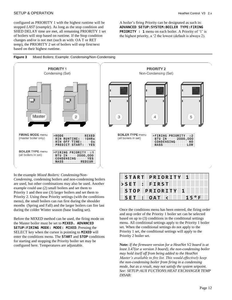
Figure 3 Mixed Boilers: Example: Condensing/Non-Condensing
In the example Mixed Boilers: Condensing/Non-
Condensing, condensing boilers and non-condensing boilers
are used, but other combinations may also be used. Another
example could use (2) small boilers and set them to
Priority 1 and then use (3) larger boilers and set them to
Priority 2. Using these Priority settings (with the conditions
menu), the small boilers can run first during the shoulder
months (Spring and Fall) and the larger boilers can fire last
during the colder Winter season (base loading set).
Before the MIXED method can be used, the firing mode on
the Master boiler must be set to MIXED. ADVANCED SETUP:FIRING MODE: MODE: MIXED. Pressing the
SELECT key when the cursor is pointing to MIXED will
enter the conditions menu. The START and STOP conditions
for starting and stopping the Priority boiler set may be
configured here. Temperatures are adjustable.
Once the conditions menu has been entered, the firing order
and stop order of the Priority 1 boiler set can be selected
based on up to (3) conditions in the conditional settings
menu. All conditional settings apply to the Priority 1 boiler
set. When the conditional settings do not apply to the
Priority 1 set, the conditional settings will apply to the
Priority 2 boiler set.
Note: If the firmware version for a HeatNet V2 board is at
least 3.47(or a version 3 board), the non-condensing boiler
may hold itself off from being added to the HeatNet
Master’s available to fire list. This would effectively keep
the non-condensing boiler from firing in a condensing
mode, but as a result, may not satisfy the system setpoint.
See: SETUP:AUX FUCTIONS:HEAT EXCHANGER TEMP
DISAB:
S T A R T P R I O R I T Y 1
> S E T : F I R S T
S T O P P R I O R I T Y 1
S E T : O A T < 1 5 ° F

SETUP & OPERATION HeatNet Control V3 2.x
Page 13
Start/Stop Priority Conditions
The following is an example using mixed condensing and non-condensing boilers:
FIRE FIRST
Condensing boilers may be configured to fire first (set to
PRIORITY 1) when:
2. The Return water temperature is below 140F and
condensing occurs. (The Master‘s return water sensor
would need to be moved to the header return.)
3. The Outside Air Temperature is above a setpoint
determined by the system configuration. This setpoint
ensures that the more efficient condensing boilers run
first during shoulder months (Spring and Fall) when
minimal heating is required. Below this setpoint, larger
boilers should be brought on first to ―base load‖ the
system.
4. Greater efficiency is required.
STOP FIRST
Condensing boilers may be configured to stop first (set to
PRIORITY 1) when:
The Return water temperature is above 140F and
condensing is minimized, thus leaving the larger lower cost
boilers running to carry the load.
1. The Outside Air Temperature is below an adjustable
setpoint determined by the system configuration. This
setpoint ensures that the larger non-condensing boilers
run during the coldest months when maximum heating
is required. Above this setpoint smaller condensing
boilers should be brought on first to run the system as
efficiently as possible.
2. Maximum heating is required
START PRIORITY 1 SET
Selections (always the lowest runtime first):
The condensing boiler set (Priority 1) has a higher Priority to fire when one of these conditions is met. Values are adjustable.
FIRST: The condensing boilers (Priority 1) are always
started FIRST
OA T > 15F: The condensing boilers (Priority 1) are
started when the OA temperature is greater than the Mixed
Boiler Outdoor Air Temperature setting.
RET < 140F: The condensing boilers (Priority 1) are
started when the Return water temperature is less than the
Mixed Boiler Return temperature setting (This may not
applicable in most configurations since the local return
temperature on the Master is used to provide a difference
temperature across the heat exchanger. A System Return
sensor will be required. However, the return temperature
sensor may have been moved on the Master to provide
system return temperature on existing installations and is
still supported).
STOP PRIORITY 1 SET
Selections (always the highest runtime first):
The condensing boiler set (Priority 1) has a higher Priority to stop when one of these conditions are met. Values are adjustable.
LAST: The condensing boilers (Priority 1) are always
stopped LAST.
OA T < 15F: The condensing boilers (Priority 1) are
stopped first when the OA temperature is less than Mixed
Boiler Outdoor Air Temperature.
RET > 140F: The condensing boilers (Priority 1) are
stopped first when the Return water temperature is greater
than the Mixed Boiler Return temperature. (This may not
applicable in most configurations since the local return
temperature on the Master is used to provide a difference
temperature across the heat exchanger. However, the return
temperature sensor may be moved on the Master to provide
system return temp if the difference temp is not required)
Start/stop settings
Any combination of Start Conditions and Stop Conditions
can be used to optimize the mixing of condensing
(Priority 1) and non-condensing boilers (Priority 2) for best
performance/economy.
The default settings for the start and stop conditions of the
condensing set are:
The default start setting always starts the condensing boilers
(Priority 1 example) first, except for the lead boiler setting.
The lead boiler will always start first if enabled, unless
there is a boiler already running (this includes a Member
boiler in LOCAL). The default stop condition setting always
stops the condensing boilers (Priority 1) last.
If prolonging the life of the heat exchanger(s) on non-
condensing boilers is very important, consider starting the
condensing boilers (KN series) when the return water
temperature is below 140F.
S T A R T P R I O R I T Y 1
> S E T : F I R S T
S T O P P R I O R I T Y 1
S E T : L A S T

SETUP & OPERATION HeatNet Control V3 2.x
Page 14
The return water temperature sensor would need to be moved from the Master‘s return inlet to the system return. The EXCHGR DELTA may need to be adjusted in SETUP:AUX FUNCTIONS:HEAT EXCHANGER to prevent the Master from going to ½ input when a high DELTA T is reached.
This method would lead to the non-condensing boilers
carrying the load when the system temperature stabilizes
above 140F, since non-condensing boilers will start first
with the Return water temperature is > 140F. The
condensing boilers can then be stopped first when the RET
water temperature is above the 140F. Remember, any
combination of the Start and Stop conditions may be applied
for best performance and economy in the system. Also, non-
condensing boilers may be set to go offline when a return
temperature is too low using the SETUP:AUX
FUNCTIONS: HET EXCHANGER: TEMP DISAB menu..
Base load boilers can also be mixed in the same way as
condensing and non-condensing boilers. The base load
boiler(s) can be prioritized in one set (example, Priority 2)
and non-base load boilers (Priority 1). The non-base load
boilers can then be set to fire first and once they are all
firing, the base load boiler would fire.
To minimize the cycling of a large base load boiler, consider
using the stop condition. Change it to the OA T < 15F
(Outside Air Temperature) condition. This setting may be
used to stop the Priority 1 boiler set when the OA T drops
below the OA T setpoint, thus leaving the large base loaded
boiler on and shutting off the condensing boilers first. This
is also true when using the OA T setting to start the
Priority 1 boiler set when the OA T is above the start
setpoint. To use temperatures as start and stop conditions,
the system design temperatures must be known.
Selecting Mixed Boilers
There are a few factors to consider when choosing which
type of boilers to use in a mixed system. These factors need
to be considered when boilers are added or shed. When
BTUs are introduced into the system by adding boilers, the
amount of introduced BTUs should be smooth (linear). If
these factors are not considered, discontinuity in BTUs may
occur when boilers are added and as a result, short cycling
will occur.
1. Turndown: This is the ratio of minimum fire rate to
maximum fire rate: Example: a 20% minimum
modulation = 5:1 turndown (100%mod / 20% mod). A
(1) million BTU boiler = 200,000 BTUs minimum
input.
2. MOD MAX CLAMP: This value determines the
maximum modulation % at which the boilers will fire
to until all available boilers are firing.
3. Total System BTUs.
4. Desired Effective Turndown. This is the lowest
firing rate of the system relative to the maximum firing
rate of the system. The larger the value, the lower the
BTUs that can be delivered to a light load.
5. Piping.
Mixed System Type 1: High System Turndown
The following examples are of mixed boiler systems with
high effective system turndown and fault tolerance built in.
When boiler types are the same, the system turndown is
limited to the boiler‘s min input and fault tolerance is
always present. When the system has mixed boiler types,
consideration needs to be taken on what types can be mixed
properly to achieve a high system turndown and provide
some fault tolerance.
Fault tolerance allows for one boiler in the Priority 1 system
to fail and any boiler(s) in the Priority 2 system to fail and
still provide near linear (continuity) BTU response when
adding boilers. This is illustrated in the following examples
using the Boiler System Response graphs.
The KN Mixed Boiler System (examples) is advantageous
in providing low BTU input for light loads and high BTUs
for heavy loads. The effective system turndown minimizes
short cycling when light loads are present by assigning
smaller boilers to Priority 1, running them first, and then
stopping them last.
In order to achieve the high effective turndown, smaller boilers are required (plumbing considerations need to be considered here due to differing flow/volume characteristics through the large and small boilers).
Example Systems:
Figure 4 Non-Mixed Boiler System
System MMBTU
Effective Turndown
MOD MAX
MB/MW 4:1
10.0 25:1 70% KN20, KN20,
KN20, KN20, KN20
5.0 25:1 70% KN10, KN10,
KN10, KN10, KN10
3.0 25:1 70% 500, 500, 500, 500,
500
With the traditional Non-Mixed boiler system, the effective
turndown increases by the turndown ratio for every boiler

SETUP & OPERATION HeatNet Control V3 2.x
Page 15
added. The min fire rate is equal to the minimum BTUs that
can be delivered to the system.
Number of boilers * Turndown Ratio = Effective System
Turndown: 5 * 5:1 = 25:1.
Figure 5 Mixed Boiler System
System MMBTU
Effective Turndown
MOD MAX
Priority 1 5:1
Priority 2 4:1
4.2 35:1 60% KN6, KN6 KN10, KN10,
KN10
3.8 42:1 70% KN4, KN4 KN10, KN10,
KN10
2.2 55:1 81% KN2, KN2 KN6, KN6,
KN6
3.6 90:1 72% KN2, KN2,
KN2 KN10, KN10,
KN10
With the mixed boiler system, a lower minimum fire
rate/BTU can be delivered to the system by using small
boilers with larger boilers. This works in much the same
way as base loading.
Figure 6 KN Boiler Btu Chart (MBH)
KN2 KN4 KN6 KN10 KN20 KN30
Max Input 200M 400M 600M 1MM 2MM 3MM
Min Input 5:1
40M 80M 120M 200M 400M 600M
Mod Max 80%
160M 320M 480M 800M 1.6MM 2.4MM
Mod Max 70%
140M 280M 420M 700M 1.4MM 2.1MM
Mod Max 60%
120M 240M 360M 600M 1.2MM 1.8MM
Mod Max 50%
100M 200M 300M 500M 1MM 1.5MM
When selecting the Priority 1 boiler(s) for a high effective
system turndown, the BTU Min Input is selected first. (See:
KN Fusion & Boiler Btu Chart). Next, the MOD-MAX
value of this Priority 1 boiler needs to be greater than: Mod
MAX % =
(Priority 1 „s Min Input + Priority 2 „s Min Input)
Max Input of the Priority 1 boiler
The reason for this is keep the continuity of BTUs linear
without a BTU bump (discontinuity) when boilers are added
or shed. This is illustrated in the Boiler System Response 2
graph.
If redundancy is not required, the min inputs of the
Priority 1 boilers may be summed to lower the Mod Max %
value so smaller Priority 1 boilers can be used. The sum of
the min inputs would then need to be divided by the sum of
the Max Input of the Priority 1 boilers. The effect of this
would create a higher turndown. See: EXCEPTION NOTES:
Mod MAX % =
( ((Priority 1 Min) * (#Priority 1‟s)) + Priority 2 Min)
Max Input of Priority 1 boiler * (#Priority 1‟s)
Example: (2) KN6s, (2) KN20s
Redundancy: (120 + 400)/600 = 87%
No Redundancy: (120 * 2) + 400)/(600*2) =54%

SETUP & OPERATION HeatNet Control V3 2.x
Page 16
EXCEPTION NOTES:
1. Mixing more than two different size/type boilers
becomes more complex than the scope of this manual.
2. If using more than one Priority 1 boiler and the
calculated value is <
Priority 1Min * 2
Priority 1 Max Input
Use this result PLUS note 3 value as the ModMax%.
3. Always add a few % (3-5%) to the calculated MOD
MAX % value to allow a guard band (tolerance).
4. If boilers are of different sizes, try to use larger
Priority 2 boilers.
If the calculated Mod MAX % value is greater than 99%, the combination cannot be used since short cycling will occur.
Once the Priority 1 and Priority 2 boilers are selected, they
can be multiplied in each Priority set to achieve the desired
system design BTUs. If the # of boilers becomes a large
number, a Priority 1 boiler with a higher Min Input may
need to be selected.
While considering the MOD-MAX value, the lower the
MOD-MAX the greater the combustion efficiency since it
effectively limits the input rate. The Typical Efficiency of
Non-Condensing Boilers chart can help illustrate how the
MOD-MAX value can affect the efficiency by limiting the
input until all boilers have fired. Non-condensing boiler
efficiency is relatively flat compared with condensing as
illustrated in the Typical Efficiency of Condensing Boiler
graph.
Figure 7 Typical efficiency of condensing boilers (GAMA BTS2000 method)
In the Mixed Boiler System table (line 1), KN6s are set as
Priority 1 and KN10‘s set as Priority 2. With a MOD MAX
of 60%, each KN6 can run to 360M (720M total) before a
KN10 is called ON (Add Delay timer set long enough).
Once both KN6s are running and the KN10 is then called on
and running, all (3) boilers will drop to a total of the 720M
BTUs: The sum of the KN6, KN6, and KN10. About 33%
modulation: (.33* 600M) + (.33* 600M) + (.33* 1MM) or:
198M +198M + 330M = 726M and operate at higher
combustion efficiencies. 33% is roughly between the top
two lines on the Typical Efficiency of Condensing Boilers
chart.
Figure 8 Boiler System Response 1 (2) KN2s, (3) KN6s
When running non condensing boilers at low input rates, the risk of condensing should be considered.
The Boiler System Response 1 chart illustrates how each
boiler (in the example) is brought on and fires to 60%, drops
to a lower fire rate and then adds the next boiler (vertical
dashed lines). Once all boilers are firing, the modulation is
released allowing all boilers to fire to 100%. So, for the first
2500 MBTH of load, the combustion efficiency is
maximized by running the boilers from low to middle input
rates.
Now if a (2) boiler system (one of the KN6s & two KN20s
brought offline) using (1) KN6 with (1) KN20 and MOD-
MAX set to 60%, the KN6 would fire to 360 MBTUs and
wait for the KN20 (Boiler System Response 2 graph). Once
the KN20 fired, the input rate would jump to 520 MBTUs,
400M (KN20 @ 20%) + the 120M (KN6 @ 20%). There
would be 160 MBTUS more than needed.
The PID algorithm would then compensate for the large
discontinuity (over fire bump) in BTUs and the KN20
would shut off (short cycle). This discontinuity is observed
in the graph below, (Boiler System Response 2) where the
jump from the KN6 @60% to the firing of the KN20 is
apparent.

SETUP & OPERATION HeatNet Control V3 2.x
Page 17
Figure 9 Boiler System Response 2 (1) KN6, (1) KN20, 60% Mod-Max
To correct this would require the KN6 to set the MOD-
MAX to roughly 90% (Boiler System Response 3: not as
efficient as it could be) in order to have a linear BTU
transfer when the KN20 is added (fired).
Figure 10 Boiler System Response 3 (1) KN6, (1) KN20, 90% Mod-Max
A KN6 running with a KN20 may not be an optimal choice
unless (2) KN6‘s are always functional and used in the
Priority 1 set or (3) KN6s and one is allowed to be taken
offline.
A system employing this redundancy where (1) is allowed
to be taken offline is listed in the MIXED BOILER
SYSTEM chart. The example system uses (3) KN2s and (3)
KN10s. Two of the KN2s are treated as one when adding
the min inputs of the Priority 1 set.
Figure 11 Boiler System Response 4 (2) KN2s, (3) KN6s
The above Boiler System Response 4 graph illustrates
another system where 80% is used as the MOD-MAX
clamp.
In summary, the system should be tuned using the boiler
selection charts and the MOD-MAX value so that boilers
are brought on and fired in their respective efficiency curve
while maintaining continuity in BTUs. Since selecting the
Priority 1 boiler is integral to the fault tolerance of the
system, it is important to note any discontinuities in BTUs if
a Priority 1 boiler fails when multiple Priority 1 boilers are
used.
SETUP & OPERATION HeatNet Control V3 2.x
Page 18
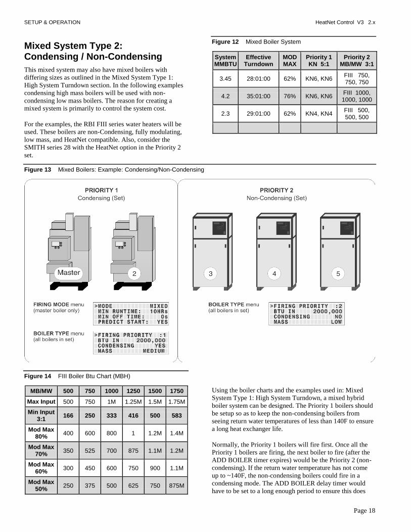
Mixed System Type 2: Condensing / Non-Condensing
This mixed system may also have mixed boilers with
differing sizes as outlined in the Mixed System Type 1:
High System Turndown section. In the following examples
condensing high mass boilers will be used with non-
condensing low mass boilers. The reason for creating a
mixed system is primarily to control the system cost.
For the examples, the RBI FIII series water heaters will be
used. These boilers are non-Condensing, fully modulating,
low mass, and HeatNet compatible. Also, consider the
SMITH series 28 with the HeatNet option in the Priority 2
set.
Figure 12 Mixed Boiler System
System MMBTU
Effective Turndown
MOD MAX
Priority 1 KN 5:1
Priority 2 MB/MW 3:1
3.45 28:01:00 62% KN6, KN6 FIII 750, 750, 750
4.2 35:01:00 76% KN6, KN6 FIII 1000, 1000, 1000
2.3 29:01:00 62% KN4, KN4 FIII 500, 500, 500
Figure 13 Mixed Boilers: Example: Condensing/Non-Condensing
Figure 14 FIII Boiler Btu Chart (MBH)
MB/MW 500 750 1000 1250 1500 1750
Max Input 500 750 1M 1.25M 1.5M 1.75M
Min Input 3:1
166 250 333 416 500 583
Mod Max 80%
400 600 800 1 1.2M 1.4M
Mod Max 70%
350 525 700 875 1.1M 1.2M
Mod Max 60%
300 450 600 750 900 1.1M
Mod Max 50%
250 375 500 625 750 875M
Using the boiler charts and the examples used in: Mixed
System Type 1: High System Turndown, a mixed hybrid
boiler system can be designed. The Priority 1 boilers should
be setup so as to keep the non-condensing boilers from
seeing return water temperatures of less than 140F to ensure
a long heat exchanger life.
Normally, the Priority 1 boilers will fire first. Once all the
Priority 1 boilers are firing, the next boiler to fire (after the
ADD BOILER timer expires) would be the Priority 2 (non-
condensing). If the return water temperature has not come
up to ~140F, the non-condensing boilers could fire in a
condensing mode. The ADD BOILER delay timer would
have to be set to a long enough period to ensure this does

SETUP & OPERATION HeatNet Control V3 2.x
Page 19
not happen. Even then, the load may be too great. The
following note will explain an alternative way (not
depending on the ADD BOILER DELAY) to keep non-
condensing boilers from firing in a condensing mode.
When running with a remote BMS setpoint, care must be
taken that an Outside Air reset setpoint (or other setpoint)
sent by the BMS is not set too low. If the BMS system is
controlling the setpoint close to the condensing temperature,
the return water temperature may never rise sufficiently to
keep boilers out of a condensing mode. HeatNet online is a
good way to monitor this scenario if suspected.
NOTE:
If the firmware version for a HeatNet V2 board is at least
3.47(or a version 3 board), the non-condensing boiler
may hold itself off from being added to the HeatNet
Master’s available to fire list. This would effectively keep
the non-condensing boiler from firing in a condensing
mode, but as a result, may not satisfy the system setpoint.
In order to use this feature, the version 2 board would
need to monitor the system or local return temperature.
This can be done locally by setting SETUP: AUX
FUNCTIONS: HEAT EXCHNAGER: TEMP DISAB:
RETURN if the there is no pump/valve limiting flow
continuously through the boiler. If there is a pump/valve
limiting the flow through the boiler, the SETUP: AUX
FUNCTIONS: HEAT EXCHNAGER: TEMP DISAB: SYS
RET needs to be set. Then the Master boiler needs to set
SETUP: AUX FUNTIONS: HEAT EXCHNAGER: SEND
RETURN: to which of its return temperatures it would
send to all boilers. These include the Local Return
temperature or the System Return temperature.
The Member’s menu “SETUP: AUX FUNCTIONS: HEAT
EXCHNAGER: TEMP DISAB:” if set to RETURN or SYS
RET, will force the boiler to become unavailable to
HeatNet when the SETUP: AUX FUNCTIONS: HEAT
EXCHNAGER: TEMP< 140F. This value is adjustable to
135F if a forced air fan is used. When the SYS RET or
RETURN temperature is <140F the boiler responds to a
HeatNet Master’s request as” unavailable”. As soon as
the return temperature reaches 140F, the boiler will
respond to the Master’s request that it is available to fire.
If the Master boiler is a version 2 board, the Master will
always transmit its Local Return temperature to all
boilers. If the Master is set to Priority 1 and all other
non-condensing boilers are set to Priority 2, the Master
should always remain on if there is a call for heat. This
requires that the Priority 1 boiler be set up to start first
and stop last. Using this method should always send a
valid return temperature to the Member boilers. This
method can also be used with a version 3 board, but a
system return sensor is preferred.
When this condition is in effect, the STATUS * screen will
indicate “blr offline”. While the boiler is in this “not
available” state, it can still be fired locally and failsafe is
still available.
SETUP: AUX FUNCTIONS:HEAT
EXCHANGER:SEND RETURN:
OFF The Master sends its return
temperature to all boilers
RETURN The Master sends its return
temperature to all boilers
SYS RET The Master sends the system
return temperature to all
boilers
SETUP:AUX FUNCTIONS:HEAT
EXCHANGER:LOW TEMP:
OFF No check is made to the return
temperature – boiler remains
online
RETURN Uses the boilers own return
sensor (No pump /valve
present)
SYS RETURN Uses the System Return temp
received from the Master Boiler
(its Local or System Return).
SETUP:AUX FUNCTIONS:HEAT
EXCHANGER:TEMP < 140F
Adjustable threshold temperature below which the
boiler will take itself offline.
(1) degree F of hysteresis is provided so as to not
toggle offline<-to->online at the threshold temp.
Since the FIII boiler is non-condensing, the efficiency vs.
input is relatively flat. The MOD MAX value will not have
the same impact if the FIII non-condensing boilers were
placed in the Priority 1 set.

SETUP & OPERATION HeatNet Control V3 2.x
Page 20
KN Boiler Btu Chart (MBH)
KN2 KN4 KN6 KN10 KN20 KN30
Max Input
200 400 600 1MM 2M 3M
Min Input 5:1
40 80 120 200M 400 600
Mod Max 80%
160 320 480 800M 1.6M 2.4M
Mod Max 70%
140 280 420 700M 1.4M 2.1M
Mod Max 60%
120 240 360 600M 1.2M 1.8M
Mod Max 50%
100 200 300 500 1M 1.5M

CONTROL METHODS HeatNet Control V3 2.x
Page 21
Base Loading, Relay Control
The control has the ability to control (1) base load boiler
using the K8 Relay contacts on J4 pins 2 & 6. In order to
connect to this plug, (2) wires with pins are required and
inserted in J4. Base Loading via relay requires these (2)
flying leads (loose wires available from the factory) to be
inserted into J4, pins 2 & 6. These (2) wires then make up
the Normally Open contacts. This feature also can be used
on Master or Member boilers. The solid state relay K8, with
contact connections on J4.2 & J4.6 has a rating of: 0.1 to 1
Amp.
If the base load boiler is of the modulating type, a 4-20mA
signal is also provided on J4 pins 1 and 5. Jumper shunt JS1
will then need to be set to 4-20mA position. Two additional
wires (available from the factory) will need to be added to
the J4 pins at 1 & 5. Pin 1 is the + output of the 4-20mA
transmitter, and pin 5 is the – output. This modulating
control signal is used to modulate the base load boiler along
with the HeatNet boilers in parallel. The ADAPTIVE MOD
does not function in lowering the modulation rate when the
base load boiler is added. The PID will adapt to the newly
fired base load boiler and lower its modulation rate when
the increase in water temperature is observed.
Figure 15 Base loading with KN boilers
Enable the base load feature by setting:
ADVANCED SETUP:SYSTEM:OPTION to BASE LOAD. This
setting the OPTION Relay to be used as control for a Base
Load Boiler.
1. ADVANCED SETUP:SYSTEM:OPTION to BASE LOAD.
This setting the OPTION Relay to be used as control
for a Base Load Boiler.
2. The ADVANCED SETUP:BASE LOAD BOILERS: BASE LOAD BOILERS: to 1. Currently allows (1) base
load boiler.
3. The START & STOP qualifier condition to the method
discussed below.
4. The DELAY TIME to the amount of time required after
the start qualifier condition has been met to start the
boiler.
If a MINIMUM OFF time of the Base Load boiler is
needed, the Base Load boiler will share the MIN OFF TIME
of the boiler controlling it. If the base load boiler was
running and shuts off, the MIN OFF TIME will need to
expire before the boiler can start again. Once this time
expires, the DELAY TIME also needs to expire to start the
boiler. This will help in minimizing short cycle conditions
and can be set at: ADVANCED SETUP:FIRING MODE: MODE:MIN OFF TIME.
Preferred:
A modulating base load boiler that can accept a 4-20mA
control signal such as the SMITH 28 series (and is
preferred) or a non-modulating base load boiler that is sized
correctly to the H-Net boilers. The Smith 28 series also has
a HeatNet option. A 135 ohm input for the base load boiler
will need a converter from 4-20mA to 135 ohm .
http://www.smithboiler.com/
If the base load boiler is not of the modulating type,
stopping the Base Load boiler will require that the size of
the Base Load boiler in BTUs to be known relative to the
HeatNet boilers. Boiler selection is ideally; having more
total BTUs in the HeatNet boilers than total BTUs of the
Base Load boiler. This will prevent short cycling. Example:
(4) 2 million BTU HeatNet boilers = 8 million BTUs and
(1) 6 million BTU Base Load boiler.
When all (4) HeatNet boilers are running @ 95%, the Base
Load boiler is called on (demand is approx. 8 million
BTUs). As the Base load boiler comes on it introduces 6
million BTUs and the HeatNet boilers modulate down to
25% for a total output of 2 million BTUs and running at
high efficiency. The HeatNet boilers can now modulate to
the load from 1.6 million BTUs (20% mod) to another 8
million BTUs.

CONTROL METHODS HeatNet Control V3 2.x
Page 22
Not Preferred:
Example of having a larger Base Load boiler that is not of
the modulating type: If there is a 6 Million BTU Base Load
boiler running with (3) 2 million BTU HeatNet boilers, a
short cycling situation will arise when the (3) 2 million BTU
boilers are running @ 95% and the Base Load boiler is
called on. At this point there is a need for approximately 6
million BTUs. The (3) smaller boilers will then modulate
down to low fire. At this point, the (3) smaller boilers need
to shut off or the Base load boiler would need to shut off.
There is no overlap. A selection for stopping the boiler now
needs to be determined. Setting the Stop qualifier;
Modulation to 40% or a low fire rate will shut the Base
Load boiler off and allow the (3) smaller boilers to modulate
up again (short cycle of the Base Load boiler; Use the Delay
Timer and Min OFF timer). The Stop qualifier; OA T >
xxF may also be used if the system design temperature is
known. Then let the Base Load boiler cycle off of its limits,
whether a 2 stage, Hi/Lo, or modulating boiler. The default
setting is for the Base Load boiler to stop first once the
water temperature exceeds the top of the heating band.
Figure 16 Base loading relay
Base Load RIB Relay
24 VAC
24 VAC Return, or
Chassis Ground
Enable Input on
Base Load Boiler
1. First ensure that the ADVANCED
SETUP:SYSTEM:OPTION: is set to BASE
LOAD. The Base Load Relay (K8) will not be
enabled/used unless this is selected.
2. Now, The ADVANCED SETUP:BASE
LOAD:BASE LOAD BOILERS: must be set to 1.
3. When the START condition in the BASE
LOAD BOILERS menu is met, the K8 relay will
close. But, only when the DELAY TIME under
the BASE LOAD BOILERS menu expires.
Base Load Relay

CONTROL METHODS HeatNet Control V3 2.x
Page 23
Setting up base loading
The base load boiler is controlled using a set of contacts to
enable it (location J4). Enabling/Disabling this relay contact
can be done using any combination of (3) qualifiers to start
the boiler and (4) to stop the boiler. These qualifiers are:
1. Modulation %:
a. START menu item: The relay contact will close
when the MOD % from the Master boiler exceeds
this value. ADVANCE SETUP:BASE LOADING: START>MOD
b. STOP menu item: The relay contact will open when the MOD % from the Master boiler falls below this value. ADVANCE SETUP:BASE LOADING: STOP<MOD
If the START>MOD value is set to a value higher than the ADVANCED SETUP:MOD-MAX: all boilers will be firing before this modulation rate is reached. This will ensure that all available boilers are firing before the base load boiler relay is enabled.
c. Setting the : STOP<MOD to a % value slightly above
the min fire rate % of the system will ensure that
the base load boiler will stop before the first
condensing boiler stops. This is due to the
Modulation rate being close to the min modulation
rate before the water temperature exceeds the top
of the heating band.
2. Outside Air Temperature:
a. START menu item: The relay contact will close
to enable the boiler when the OA T read from the
Outside Air Temperature sensor (if Equipped) falls
below this temperature. ADVANCE SETUP:BASE LOADING: START< OA T
b. STOP menu item: The relay contact will open to
disable the boiler when the OA T read from the
Outside Air Temperature sensor (if equipped) rises
above this value. ADVANCE SETUP:BASE LOADING: STOP> OA T
If the OA T qualifier is used as the Start and Stop qualifier, ensure that there is at least a few degrees difference for hysteresis.
3. Return Water Temperature
a. START menu item: The relay contact will close to enable the boiler when the RET read from the Return Water Temperature sensor (if Equipped) falls below this temperature. ADVANCE SETUP:BASE LOADING: START> RET
b. STOP menu item: The relay contact will open to disable the boiler when the RET temperature read from the Return Water Temperature sensor (if Equipped) rises above this temperature. ADVANCE SETUP:BASE LOADING: STOP< RET
4. FIRST:
a. STOP menu item: The relay contact will open to disable the boiler when the temperature exceeds the heating band. This gives the result of stopping the Base Load boiler First. Default setting.
Delay time
The DELAY TIME is also included to hold off starting the
boiler until the delay time is met. Once the start condition
qualifier term is met, the DELAY TIME will start counting
down. When the time expires, the base load relay contacts
will close. ADVANCE SETUP:BASE LOADING:DELAY TIME. It is adjustable in a range of: 0 to 60 minutes.
Base Load Failsafe
If :
1) There are no boilers available to fire (offline or
faulted).
2) There are no boilers in local override.
3) There is a call for heat.
The J4 Base Load relay will close.
If a boiler becomes available and needs to fire, the Base
Load boiler will remain firing until the temperature exceeds
the band. This is provided to keep the system from entering
a no heat situation.

CONTROL METHODS HeatNet Control V3 2.x
Page 24
Heating Control Methods
An overview of the (5) methods for controlling the KN
series boiler are presented here. They are outlined in more
detail at the end of this section.
Heating Method 1
The first method is to use the KN Series boiler in its stand-
alone modulating method. This method uses a PID
algorithm to maintain a setpoint and is enabled using the
HEAT DEMAND input. Closing a relay contact or switch
across the HEAT DEMAND input will cause the Master
boiler to control all member boilers using H-Net.
A member boiler may also be controlled by the HEAT
DEMAND input (LOCAL mode). The member boiler will
then ignore commands from the Master and maintain its
LOCAL SETPOINT at the supply sensor.
Heating Method 2
The second method is to view the KN boiler as two separate
boilers or as a HIGH/LOW boiler using T1 & T2.
Heating Method 3
The third method is to allow a remote 4-20 ma or 0-10 VDC
signal to control the firing rate (modulation) of the boiler
using the 4-20ma input, along with the 4-20ma REMOTE
ENABLE input.
Heating Method 4
The fourth method turns the boiler ON and OFF @ 100%
modulation using the AA terminal.
Heating Method 5
The fifth method uses an RS485 digital communications
cable with the MODBUS protocol. The boiler is controlled
by writing and reading registers using MODBUS
commands. A bridge module may also be used to convert
BACnet or LonWorks protocols to MODBUS.
Short cycling may occur when a firing rate is sent to a member boiler that would cause the supply temperature to raise high enough to trip the operating limit (low flow rate). After the supply temperature falls, the boiler would restart and the process may continue. A member boiler would use its supply (outlet) sensor to protect itself from short cycling by limiting the firing rate coming from the Master. This occurs in the event that the member‘s supply temperature increases above the (OPERATE LIMIT- OPERATE LIMIT BAND).
Operating Limit
When the master boiler or an external control input is used
to control a member boiler (i.e. AA, T1-T2, 4-20ma, H-
Net), a software operating limit on the member boiler will
be used to limit the maximum output of the member boiler.
This operating limit can be adjusted in the
SETUP:SETPOINTS:OPERATING LIMIT.
There is also an associated operating limit band that must be
set in conjunction with the operating limit to help prevent
this LIMIT from being reached. Its purpose, is to limit the
output of the boiler as it approaches the operating limit. If
the band is set to 10 degrees, then for every degree that it
approaches the operating limit, the maximum output will be
lessened by 10%. With a band of 20 degrees, for every
degree that it approaches the band, the maximum output will
be lessened by 5%. You can think of this operating limit as
a smart aquastat which prevents the High Limit from
tripping. This method minimizes boiler short cycling when
using external inputs. The minimum setting is 1 degree and
effectively turns the limit band OFF. The default setting is
20F.
Input Priorities
The KN-Series control inputs are prioritized so that
multiple levels of external control can be employed at the
same time. This means that if we are firing the boiler with a
low Priority input and a higher Priority input is called for,
the boiler will now fire at the higher Priority input. When
the high Priority input is removed, the boiler will revert
back to the lower Priority input that is still being called.
Priority 1
The AA terminal has absolute control, and if used, will
always fire the boiler at 100% output, regardless of any
other input. The 4-20mA input may be raised to this
Priority using ADVANCED SETUP: 4-20mA INPUT:CHANNEL MODE:PRIORITY.

CONTROL METHODS HeatNet Control V3 2.x
Page 25
Priority 2
The HEAT DEMAND input is the next, and provides the
means to operate the boiler in LOCAL MODE when an
external control is not present, has failed, or needs to be
enabled or disabled. A member can override the H-Net
commands using this input.
Priority 3
If a HeatNet (H-Net) Network cable is connected between
boilers, and one is configured as a MASTER (requires
HEADER sensor), then the MEMBER boilers will be
controlled over the network by the MASTER.
Priority 4
The 4-20ma/0-10VDC input in tandem with the 4-20ma
REMOTE ENABLE input is next. Any signal over 4.02ma
or 2.01VDC will start and operate the boiler if the
REMOTE ENABLE is closed.
Priority 5
The lowest Priority is using the boiler as (2) stages
HIGH/LOW. These are the T1 and T2 inputs.
Each of these control methods will now be explained in
more detail:
Heating Method 1 HEAT DEMAND
Closing a relay contact, switch, or jumper across the HEAT
DEMAND input will enable this method. This method
allows operation as a setpoint control. As a setpoint control,
the Master (defined by having a common system supply
header sensor), on the H-Net network can command the
boiler fire rate of all Member boilers. The Master can call as
many boilers that it has available (boilers are auto-detected
over the H-Net cable by the Master) to meet its SYSTEM
SETPOINT. The H-Net cable must be connected and will
cause the amber light on the communications board to flash.
The amber light indicates an H-Net master is broadcasting
control information and a system heartbeat.
The AA terminal, the FAILSAFE mode active, 4-20ma at
PRIORITY:HIGHEST, and the HEAT DEMAND input
(LOCAL) on a Member, are the only inputs that will
override the H-Net control.
Figure 17 Heat demand input
MEMBER: Close to run at Local setpoint.MASTER: Close to control all boilers and
run at System setpoint.
Master boiler
The MASTER boiler controls the system using a PID
algorithm. Once the boiler is started, a PID algorithm is
used to produce a modulation percentage value from 0-
100%. This percentage is converted to a PWM, (P)ulse
(W)idth (M)odulation signal by each boiler. The
temperature of the water is maintained by sending this
PWM signal to the Variable Frequency Drive, which in turn
controls the blower motor. Since the main fuel valve is air-
fuel coupled to the blower, the speed of the blower provides
the firing rate.
Member boiler(s)
A Member (lacking a common system supply header
sensor) boiler may also be controlled by the HEAT
DEMAND input (LOCAL mode). The member boiler will
then ignore commands from the Master and maintain its
own LOCAL SETPOINT at its supply sensor. This can be
viewed as a manual override on a member boiler. Be sure to
observe the use of the proper use of a Common System
Damper (See: AUXILIARY FUNCTION OPTIONS
section) and any system pumps or system common
interlocks.
Features of the HEAT DEMAND input include:
1. The control is designed to predict when to start and
stop the boiler and keep the setpoint in, or as close to
the control band as possible. If PREDICTIVE START
is enabled, the boiler may start when it is in the band
and not below it. This will help to maintain a more
accurate temperature relative to the setpoint. See also:
ADVANCED SETUP:FIRING MODE:PRDICTIVE
START: to disable this feature.
2. The control can also use the Outdoor Reset feature.
This feature allows the setpoint to be changed
automatically based on the outside air temperature. If
this feature is used, the control input: OR OVR
(OUTDOOR RESET OVERRIDE), can be used to
override the Outdoor Reset feature and run from the
local setpoint. A contact closure on the ‗AA‘ input can
also override this method.
3. The 4-20ma setpoint control function works in
conjunction with this mode. This function translates a

CONTROL METHODS HeatNet Control V3 2.x
Page 26
4-20ma control signal to a setpoint mapped between
50F and 220F. These (2) temperatures are adjustable to
provide a setpoint range. The minimum start current is
also adjustable between 3.71 and 5ma. The setpoint
control feature is used in conjunction with the
REMOTE ENABLE input on J12A. This feature is
enabled in the SETPOINTS menu as:
SETPT SOURCE 4-20ma
4. There is also support for a common system damper,
Heat Exchanger support, and starting the Master first
for common venting. For an overview of each of the
menu settings see: DEFAULT SETTINGS section.
Heating Method 2 STAGE Control T1-T2
The boiler can also be operated in 2 separate stages using
the inputs T1 and T2 inputs. Its intended use is with an
external stage controller with no analog or modulation
outputs.
Closing only one of these contacts tells the boiler to operate
at MINIMUM FIRE.
1. Closing the other contact will fire the boiler at
MAXIMUM output (the same rate as closing the AA
input).
Figure 18 Stage control input
The maximum output of the boiler is based on the MAX VFD setting in the calibration mode and not the nameplate rating.
The AA, HEAT DEMAND (LOCAL) input, the H-Net, the
4-20ma input will all override the stage control inputs.
Heating Method 3 4-20ma Control
Placing a current source between the + and – 4-20ma inputs
will allow remote control of the boilers firing rate. An
adjustable starting mA current signal here will start and then
fire the boiler at the minimum fire rate. See: ADVANCED
SETUP:4-20mA INPUT: CHANNEL MODE.
See section OPTIONAL FEATURES Using the 4-20ma
input for extensive detail.
A 20ma signal will fire the boiler at the maximum firing
rate. The input current signal is viewed as a percentage to
the boiler from 0 to 100% (0-20mA). This means that a
20% (4mA) input signal is required to start the boiler, but
since the boiler is classified as having example:4:1 turn
down ratio, the boiler can only be fired as low as 25% of
output. Any signal between 20% and 25 %, will fire the
boiler at the minimum fire rate. If the MINIMUM setting of
the boiler is set above the example: 4:1 turndown of 25%
(such as 33%), a control signal change between 25% and
33% will not change the boilers firing rate. Once the control
signal rises above the MINIMUM fire rate, the control
signal will then affect control of the boilers fire rate.
The AA terminal, the HEAT DEMAND, and the H-Net
NETWORK are the only inputs that will override the 4-
20ma input.
Heating Method 4 AA Input
HIGH FIRE input Control: The AA input will fire the boiler
at HIGH fire (maximum output of the boiler). No other
inputs can override this input.
Figure 19 AA — High fire input
Method 4: Close this AA contact to run the boiler at High Fire.
Method 2 Stage Control Inputs:
T1 & T2

CONTROL METHODS HeatNet Control V3 2.x
Page 27
Heating Method 5 MODBUS communications
The fifth method uses an RS485 digital communications
cable with the MODBUS protocol to control the boiler
using the H-Net network. The Boiler or Boiler network will
run as in Method 1, but instead of the HEAT DEMAND
input, a software form of the HEAT DEMAND input is
used (40001: Boiler/System Enable/Disable). See:
MODBUS COMMUNICATIONS section.
Figure 20 MODBUS connections
Modbus Using RJ45 Cat 5 cable
Modbus Using shielded 3 wire.
Building Management
The System Setpoint Timer also needs to be loaded
periodically to allow the H-Net system to fallback to
Method 1 in the event communications is lost from the
Building Management System (BMS).
This feature can be turned off in ADVANCED SETUP:
COMMUNICATIONS: SETPOINT TIMER: OFF. If the
setpoint timer feature is set to ON, the ADVANCED
SETUP: COMMUNICATIONS: SETPOINT TIME may be
set to a time that allows any write to a MODBUS register to
reset the setpoint timer as long as it occurs within that time.
This will reset the setpoint timer without writing the
setpoint timer register. So, periodically writing the setpoint
register will automatically reset the setpoint timer as long as
the write occurs within that time window.
Protocessor option
An optional BACnet or LonWorks bridge module can be
used to connect the MODBUS network to a BACnet or
LonWorks network.
Figure 21 Protocessor bridge module option
This method allows enabling and disabling the boiler or H-
Net system, changing setpoints, reading boiler(s) status, or
temperatures remotely using digital commands. See the
section: MODBUS Communications.

OPTIONAL FEATURES HeatNet Control V3 2.x
Page 28
Using the 4-20ma input (OPTIONAL)
The 4-20ma input is designed to operate per the ISA-50.1
standard. It will support Type 2, Type 3, and Type 4
Transmitter/Receiver circuits.
The Type 2 and Type 3 circuit may use the supplied +24VDC
and 24VDC RET connections (J10B) to power a remote
transmitter. The –ma terminal will need to have a jumper
connected to the adjacent 24VDC RET terminal to reference
the signal ground.
With the type 4 configuration, multiple boilers (up to 5), may
be connected in series using the –ma +ma –ma +ma scheme
(no jumper to 24VDC RET). This allows one 4-20ma
transmitter to control multiple boilers. A free-floating 250
ohm resistor is viewed by the BMS (or external control‘s) 4-
20ma transmitter across the + and –4-20ma terminals with
this method.
Figure 22 4–20ma connections
Channel 1:4-20mA/0-10VDC
(+)
(-)Channel 2:
4-20mA/0-10VDC
(+)
(-)
24 VDC Return
24 VDC
Figure 23 4–20ma enable connection
Closing this contact enables the 4-20mA/0-10VDC input
The 4-20 ma input uses a 250 ohm sense resistor to convert
the current to a voltage from 1 to 5 volts DC for the control to
use. For this reason, a 1-5 VDC control voltage may also be
used across the 4-20mA +/- input, but it still needs to supply
the necessary current, i.e. 20mA. This resistor is located on
the bottom side of the control board. When a 4.02 ma signal is
sensed, the boiler will initiate a start sequence and fire the
boiler at its minimum setting if the REMOTE ENABLE input
is closed. This is typically 25% of the boilers output (4:1
turndown).
If the dip switch S6 is set to the 0-10 position (UP) See:
Figure 31, the 4-20mA input will accept a 0-10 VDC signal.
The channel will also need to be setup in the menu:
ADVANCED SETUP:4-20ma INPUT:CHANNEL MODE. The
operating range will be from 2-10 VDC or twice what was
previously stated for the 1-5 VDC functionality. To convert a
0-10VDC signal to mA, divide by 2510 (ohms).
NOTE: Due to the inability of control voltage methods (1-5,
2-10 VDC) to reject noise and compensate for line loss, the
use of the 4-20mA control current is recommended. The
control voltage methods may be less expensive, but are the
least stable. If using a 0-10VDC control signal, a source
current of 5mA is required.
If using a remote panel with a relay and a 4-20 ma transmitter
for operation, connect the 4-20ma transmitter output from the
remote panel to the member boilers using the floating 250
ohm method (type 4). The relay contacts on the remote panel
will then be connected to the associated 4-20ma REMOTE
ENABLE inputs on the associated boiler(s).

OPTIONAL FEATURES HeatNet Control V3 2.x
Page 29
For non Ametek blowers, the minimum setting of the boiler is calibrated so that the minimum PWM signal to control the Blower motor is 20%. The VFD to blower motor operates with a control signal from 20% - 80% Pulse Width Modulation. This PWM signal to the VFD can be measured using a multimeter. It is a 0–10volt square wave signal at 110 Hertz. A 20% modulation signal will read 2.0 VDC, and an 80% modulation signal will read 8.0 VDC on an RMS multimeter. See Figure 36, page 56.
For Ametek Blowers, the minimum signal to control the blower will be less than 20%, but the display % will be equal to the turndown % of the boiler. Also, the signal sent to the Ametek blower is twice that of non Ametek blowers, so the VDC reading will need to be divided by (2) to get the modulation % sent to the Blower. The Ametek blower also has a menu located at: ADVANCED SETUP:BLOWER SETTINGS. This menu allows the Acceleration, Deceleration, and Soft Start Values to be set for proper operation of the Blower.
For direct fire applications, the 0-10 volt
control signal is proportional to the output.
Such that: 1 volt will track linearly by 10%. So,
1v=10%, 2v=20%, 3v=30%, 4v=40%... The
control signal will still be limited by the
turndown and the 4-20mA INPUT menu. This
means that the 1v signal will have no effect on
a 5:1, 20% boiler. A ~2v signal will start the
5:1 boiler.
Setpoint Control functionality can be implemented remotely
using the 4-20mA input. This function translates a 4 to 20ma
control signal to a setpoint mapped from 50F to 220F. The
feature is enabled in the SETPOINTS menu as: SETUP:
SETPOINTS:SETPT SOURCE 4-20ma.
ADVANCED SETUP:4-20ma INPUT:CHANNEL MODE.
Also, when selecting; SETUP:SETPOINTS:SETPT SOURCE
and selecting 4-20ma, the 4-20ma INPUT menu will be
automatically entered.
You may now select the current at which the boiler will start.
It is adjustable from 3.7ma to 5ma. Hysteresis of .1ma is
always in effect. So, if the starting ma = 4.10ma the boiler
will start when the control current applied achieves this value
of 4.10ma. The boiler must drop .1ma below this to turn OFF,
in this example 4.00ma. This hysteresis value is not
adjustable.
When using the 4-20ma setpoint control, a band may now be
set at which the 4-20ma signal will operate over. The lower
setpoint is defined as 4ma SETPOINT and the upper setpoint
is defined as 20ma SETPOINT. The 4ma SETPOINT is
linked to the BOILER START x.xxma where this starting
current is the lower setpoint. So, if we set the 4ma
SETPOINT to 130F and the 20ma SETPOINT at 180F we
will have established the band. Once a starting control current
of BOILER START 4.1mA is applied, and the 4-20
REMOTE ENABLE INPUT is closed, the boiler will start and
the setpoint will be set to 130F. If a control current of 10ma is
applied the boiler will track on a linear slope towards the
20ma SETPOINT settling at a SETPOINT of ~149F. As the
current increases to 20ma, the SETPOINT will indicate 180F.
The Default setting is 4ma SETPOINT: 50F, and 20ma
SETPOINT 220F for backwards compatibility with the older
version. NOTE: anytime a new firmware version is uploaded
to the control, these values return these defaults.
Anytime a new firmware version is uploaded to the control, these values return to these defaults.
If using the direct modulation mode by applying a 4-20ma
current, only the BOILER START x.xx setting applies.
The 4-20 mA input can be set to HIGH PRIORITY. This is
done in menu: ADVANCED SETUP:4-20mA
INPUT:CHANNEL MODE. This allows a member boiler to
be taken offline and directly modulated by an external control.
If the Master is using it for heating and the 4-20mA is set to
HIGH PRIORITY, an external control can now output a 4-
20mA signal which will take over the boiler‘s fire rate. This is
typically used for DHW control.
Setpoint Priorities
Changing the setpoint can be done in many ways. If a higher
level setpoint control is lost, the next level setpoint control is
used until the System Setpoint is loaded. The setpoints are
prioritized in the following order:
1. 0-10V, 4-20Ma setpoint Control
2. BMS, Modbus Setpoint
3. Outdoor Reset Setpoint
4. Menu‘s System Setpoint
Any Setbacks that are active are then applied.

OPTIONAL FEATURES HeatNet Control V3 2.x
Page 30
Circulator Pump Options
There are provisions for a system pump(s) and a local pump.
This is to allow for primary/secondary loop configurations.
The system circulator pump is implemented using the K4,
K13 RELAY and normally open contacts at J13 SYSTEM
PUMP 1 and SYSTEM PUMP 2.
The pumps require motor contactors to isolate the on-board relay contacts. The on-board relays should never be used to energize large pumps directly. Figure 25 illustrates the connections without contactors for illustrative purpose.
Figure 24 System Pump connections
Figure 25 Local & DHW Pump connections
Local Pump/ValveNormally Closed &
Normally Open Contacts
DHWNormally Closed &
Normally Open Contacts
The system circulator pump is supported by (2) modes and
special features.
1. The first mode will allow the circulator pump to remain
on, unless the control‘s outside high air temperature
setting has been met when using OUTDOOR AIR
RESET.
2. The second mode will allow the circulator pump to be
turned on whenever there is a call for heat (any control
input). This mode will stop the circulator pump when the
call for heat is lost and the pump post purge time has
been satisfied.
The summer pump jog is a special feature that can be selected
when the system is in summer shutdown (OUTDOOR
RESET). The jog allows the system circulator pump(s) and
the local pump to run for the system pump purge time once a
week. It can be set to any day of the week and will occur at
12:01 AM. If (2) system pumps are present, and after the first
pump finishes its post purge, the second one will start and the
first one will stop.
The system flow proving switch is implemented using
SPARE 3/System Water Flow on J11A. If a flow switch is
connected to the WTR FLW interlock, the HeatNet control
will wait up to 10 seconds to prove flow. If flow is interrupted
after it has been established, an error will be displayed and the
boiler will cycle OFF. As long as there is a call for heat,
every 10 minutes the circulator pump will try to re-establish
flow and start the boiler again.
When (2) system pumps are present and flow is not
established or is lost (2) things will occur to try and keep heat
in the system.
1. When first starting a system: If after a 10 second
wait to establish flow has failed, the first pump will
change to the second pump. The second pump will now
try to establish flow for 10 more seconds. If the second
pump fails to establish flow, the HeatNet control waits
10 minutes. After the 10 minutes has expired, the
control now starts with the second pump and attempts
to prove flow for 10 more seconds. If flow does not
System Pump 1
System Pump 2
K4
K13
System Flow Prove Switch

OPTIONAL FEATURES HeatNet Control V3 2.x
Page 31
prove, the control changes to the first pump and
attempts to prove flow. This cycle will continue
indefinitely until flow is established. If flow is lost
while running: this process is also used in an attempt
to re-establish flow.
2. If PUMP ROTATION is set to PMP HRS the PUMP
ROTATION will be temporarily set to SYS HRS. This
is to prevent re-starting the failed pump due to its
runtime hours. Setting the PUMP ROTATION to SYS
HRS will allow a retry of the failed pump after the
rotation hours has expired. Power cycling of the boiler
or using the PUMP ROTATION menu will revert back
to PUMP ROTATION = PMP HRS if this was the
original setting.
For system pump modulation a 0-10Vdc control signal
output is provided at J4.3 (signal) and J4.7 (ground). This
signal is output by the Master boiler as a percent function of
the number of boilers running and can be used to set the speed
of a System Pump using a Variable Frequency Drive. Two
wires are required and need to be inserted into the J4.3 and
J4.7 positions to access this signal.
Note: This signal has a step response and is not linear to the
system or boiler‘s input firing rate.
The output signal is proportionally mapped to % using the
equation:
%VFD = (boilers running/total boilers)
The %VFD represents the stepped percentage of boilers
running where:
0Vdc = 0% (to) 10Vdc = 100%
If there are (6) boilers in a system and (2) are running, the
control signal = 33% or 3.3Vdc. This signal could then be
applied to a system pump‘s VFD to control the speed of the
pump relative to how many boilers are firing. The VFD would
need to be set appropriately to allow the correct flow through
each boiler.
In low volume systems sudden temperature changes may
occur when the flow is stepped up or down by a large
percentage. In these situations the ADAPTIVE MOD may
need to be disabled and the ORIGINAL KN method used.
Other adjustments may also be required.
Currently, no failsafe mode is available in the event the
Master boiler‘s control fails. If this method is employed, a
failsafe boiler could be used to override the control signal and
enable the system pump‘s VFD using some external wiring
and an external relay, or have the VFD default to a safe speed
on loss of the control signal.
If (2) pumps are available, pump rotation is available. The
rotation of the (2) pumps can be controlled using two
methods.
3. Pumps are switched based on the system run time
4. Pumps are switched by the difference between each
pump‘s runtime. The HeatNet control keeps a
running record of each pump‘s runtime in hours. If
a pump is taken offline or replaced. The runtimes
can then be adjusted until they become equal.
These features may be selected in the menu, SETUP:PUMP
OPTIONS:SYSTEM PUMP:PUMP ROTATION
The local circulator pump is supported by (3) modes and (2)
features.
1. The first mode allows the circulator pump to remain on,
unless the control‘s outside high air temperature setting
has been met when using Warm Weather Shutdown.
2. The second mode will allow the circulator pump to be
turned on whenever there is a call for heat (any control
input). This mode will stop the circulator pump when the
call for heat is lost and the pump post purge time has
been satisfied.
3. The third mode works much the same as mode 2, but it
allows the inlet sensor (RETURN) to be used with the
outlet sensor (SUPPLY) to keep the pump on until a delta
(difference) temperature is met. A return temperature
sensor is required for this mode, because the delta
temperature (SUPPLY – RETURN) measured is across
the boiler. In this mode, the post purge time is also used.
After the delta temp has been met, the post purge time
needs to expire before the pump is turned off. This mode
works much the same as mode 2.
PUMP/VALVE OPTION: This is a special feature of the
local circulator pump to prevent deadheading water flow
when all boilers are off. When this feature is enabled, the
master boiler will enable its local circulator pump/valve when
NO boilers are running. If boilers are running in LOCAL
override and not controlled by H-NET, but are visible to H-
NET, the pump(s) on these boilers are presumed ON. In this
situation, the master will not enable its circulator pump/valve
unless it is running.
Another feature of the PUMP/VALVE OPTION is to control
a local (primary) pump using a Variable Frequency Drive.
This feature may be required when a secondary system pump
is also variable speed. To enable this feature: SETUP:PUMP
OPTIONS:LOCAL PUMP PUMP/VALVE
OPTION:LOCAL PUMP VFD: ON. Setting this Option to
ON will map the control signal on J4 pins 1+ and 5- to the
modulation rate. (2) wires need to be run from J4.1+ and J4.5-
to the VFD‘s input connection. Ensure that the JS1 shunt

OPTIONAL FEATURES HeatNet Control V3 2.x
Page 32
jumper on the control board is in position 0-10 or 4-20mA as
required.
Auxiliary Function Options
Relay K5 and the terminal J13 DAMPER is used to control a
combustion air damper. J12B.7 & .8 are used to detect the dry
contact proof switch from the damper. A proof time of up to 4
minutes can be set before the boiler can start or an alarm
condition will occur. The Combustion Damper can be setup in
the SETUP:AUX FUNCTIONS menu.
Using the LINKED/COMMON setting, the Master boiler
controls a system damper, so in the event this damper fails to
open, the system will not start. If the Master boiler‘s system
damper fails, then no call for heat will be made to the member
boiler(s).
Using the INDEPENDENT setting, each member boiler can
control its own damper and is independent of the Master
boiler when a call for heat is made to the member. This allows
for separate dampers for each boiler. They can be wired to
J12B terminals 7 and 8.
If a common system damper is used (controlled by the Master
boiler), each individual boiler must prove that the combustion
air damper is open when it is placed in LOCAL. This may be
done using J12B terminal 7 on all boilers wired to the
damper‘s prove switch. Terminal 7 is the sense input and
terminal 8 is 24 VAC. Connecting a wire to terminal 8 is not
recommended.
See Figure 37, Common system damper wiring, Page 57.
A separate/independent 24 VAC source is recommended to be used for the damper prove switch when a common system damper is used. If you use terminal 8 to supply power from the Master and the Master is powered OFF, no boiler will be allowed to fire due to the loss of power through the prove switch. A backup boiler will also need to have the damper relay contacts wired in parallel with the Master for when the Master is powered OFF.
A second wire on the Master J12B terminal 7 is then
connected. The other end of this wire is then run to the first
Member boiler J12B terminal 7. If another member boiler is
present, a second wire can be connected to the first member
boiler J12B terminal 7 and the other end connected to the
other boiler J12 terminal 7. This method can be continued if
additional boilers are present. This input must be selected in
the SETUP:AUX FUNCTIONS:COMBUST AIR
DAMPER menu.
Outdoor Reset
The Outdoor reset feature allows the water setpoint
temperature to change dynamically with the outside air
temperature. It also provides an adjustable temperature that
shuts the boiler (or boiler system) down when the outside
temperature rises above it.
Figure 26 Outdoor reset curve, typical
The above chart shows how the water temperature setpoint
changes with the Outside air temperature. The four values of
180, 10 and 140, 70 are the default values:
WATER TEMP LOW OA TEMP
180 °F 10 °F
Water temp @
outside air temp
WATER TEMP HIGH OA TEMP
140 °F 70 °F
Water temp @
outside air temp
WWS Setpoint 72 °F
Outside air temperature
where Warm Weather
Shutdown occurs
WARM WEATHER SD=ON If set to ON here
The chart depicts what the water temperature setpoint will
equal with a corresponding outside air temperature. At an
outside temperature of 10F and below, the water temperature
setpoint will be limited to 180F. With an outdoor temperature
of 70F and above, the water temperature will be limited to
140F. The water temperature setpoint will track along the
charts plotted line with corresponding outside temperatures.
The OR OVR (Outdoor Reset Override) input on J12A can be
used to override this Outside Air Setpoint and maintain the
water setpoint at the LOCAL or SYSTEM SETPOINT value
130
140
150
160
170
180
190
10 70
Wat
er
Tem
p
Outside Temp
WATER TEMPERATURE SETPOINT

OPTIONAL FEATURES HeatNet Control V3 2.x
Page 33
when a contact is closed across this input. This can be used as
a Domestic Hot Water demand input.
Another function of the OUTDOOR RESET is the
Winter/Summer mode ( (W)arm (W)eather (S)hutdown).
With the WWS SETPOINT set to 72F and WARM
WEATHER SD set to ON, the boiler/system will enter
summer shutdown when the Outside Air temperature rises
above 72F. While in this state, the OR OVR input on J12A
can be used to bring the boiler/system on to maintain the
water setpoint at the LOCAL or SYSTEM SETPOINT value.
During WWS operation, the System pump will not be enabled
just the Local pump unless the SETUP:SYSTEM
PUMP:OVR ENAB IN WWS is set to ON. This is the System
Pump Priority mode. When SETUP:SYSTEM PUMP:OVR
ENAB IN WWS is set to OFF, the system pump will not
come on while in WWS with the OR OVR override input
closed.
Sensors
The H-Net control supports a standard 10K thermistor (Type
ACI/10K-CP). These sensors can be calibrated to the control
by entering the sensor menu and placing a precision 10k
resistor on an input.
Immersion sensors must have wells.
There is also a provision to use a 1K platinum sensor for the
stack temperature. The 10k thermistor is limited to a usable
range of 270F, and the 1k platinum sensor to upwards of
1000F. The S5 DIP switch is used to configure one or the
other.
Stack Temperature
The version 3 control also supports an optional 1k platinum
stack sensor. If the Stack Sensor is present, a warning will
occur at 325F and greater. During the Warning condition, for
every degree F over the warning temperature of 325F, the
boiler‘s input will be limited by 4% until the boiler is running
at low fire. If the SETUP: AUX FUNCTIONS: HEAT
EXCHANGER: ALARM TYPE: is set to‖ FAULT‖ the
boiler will halt and the Alarm relay will close when the Stack
temperature exceeds 350F. The boiler will then be allowed to
restart when the Stack temperature drops below 325F.
The Stack sensor should be a 1k ohm platinum type sensor.
Part # 0040-1300. To configure the 1k PT Stack sensor,
Switch S5.3 should be set to the NONE position and S5.4 set
to PLATINUM STACK. The sensor will then be auto-
detected after a power cycle.
Security
A password can be used to lock out control and setup features.
It can be enabled, but is shipped in the disabled state.
Saving Configuration Settings
Prior to upgrading firmware or when some changes need to be
done to the settings the menu ADVANCED SETUP: LOAD
DEFAULTS: CONFIG ? can be used to save the current
settings. Once the settings have been saved they can be
restored by using the ARROW keys to change between SAVE
and Restore.
F AC T O RY CA L ? N OF AC T O RY RE S E T ? N OCO N FI G ? S AV E
USB Features
The HeatNet V3 control supports a USB updating system and
desktop connectivity using the HeatNet Control Pro software.
In order to ensure that a valid firmware file is always
available on the HeatNet board, (2) file storage locations are
available. A firmware file is loaded at the factory in both
locations. This is to ensure that if a bad file is loaded by the
user, the factory loaded file can be re-loaded to get the board
functional again.
The firmware loading menu is located at; ADVANCED
SETUP: SYSTEM: LOAD FIRMWARE. The following
explains the menus.
Selecting USB DRIVE will read the FIRMWARE directory
on a flash drive and display any .hex files located there. The
USB flash drive needs to have a directory called ―firmware‖
located in the root directory. The downloaded firmware .hex
file needs to be placed there. Then the flash drive needs to be
inserted intoJ6 on the HeatNet control board. Follow the on
screen prompts and then select the file using the arrow keys.
Once a file has been selected, a STORAGE LOCATION
needs to be selected. There are (2) storage locations for the
new file. Location 1 is used for normal updates and Location
0 is for the factory stored backup file. When the Storage
location (default is Location 1) is selected the file will be
loaded into a permanent storage memory location. Next, the
control will reboot and copy this new program into running
memory, reboot, load factory defaults, and then reboot again.

OPTIONAL FEATURES HeatNet Control V3 2.x
Page 34
Selecting USB CABLE requires connecting a USB cable and
running the Firmware Update program from a PC. This
process takes much longer and requires a Personal Computer
(laptop) to be taken to the boiler site. Again, follow the on
screen prompts to down load the program into a storage
location as done when using the above USB DRIVE loading
menu. You will need the HeatNet Pro software which can be
downloaded from the website.
Selecting SAVE FILE will display the currently stored files
in the storage memory locations. Use the arrow keys to select
a stored file for copying to running memory. When SELECT
is pressed the file will be marked so it will be loaded on the
next power cycle. Power cycle the boiler to begin copying the
file from stored memory to running memory.
NOTE: to access the factory backup program, the P3 BOOT
shunt on the HeatNet control board needs to be connected and
the CAL/NORMAL switch placed in the CAL position. The
BOOT jumper is located close to where the ribbon cable for
the display plugs in. If the control is power cycled in this
condition, the factory program will overwrite the existing
running program. If in the LOAD FIRMWARE menus,
STORAGE LOCATION 0 will be an allowed storage
location.
Diagnostics
The H-Net control can display and identify faults in a
meaningful way. If an interlock trips, it will be indicated in
the main screen display, along with an audible alarm
(mounted on control board) and a set of relay contacts will
close. A record of this, with a time stamp, will also be entered
into the log as an aide in the diagnosis of the event. The log
can be downloaded and a histogram used to display the data.
If using Modbus, BACnet, or LonWorks, there are software
flag bits in registers available.
Open and shorted sensors are checked continuously, so that in
the event of a sensor failure, the system shuts down and the
alarm relay is closed.
If a pump fails (flow switch required), or the flow switch
fails, the boiler will cycle the start condition every 10 minutes
in an attempt get the boiler restarted.
If the damper fails to open and never closes its proof switch, a
retry algorithm will attempt a retry. Every 10 minutes the
damper relay will cycle and try to open the damper again.
If the H-Net control closes the last interlock string connected
to the ignition control and the ignition control never closes its
Blower Relay, the H-Net control will wait 2 minutes. The H-
Net control will then retry for the duration of the local pump
post purge time and then retry the ignition sequence. During
this time ―retry strt‖ will be displayed in the status screen.
After (5) attempts the H-Net control will lock out and display
call service.
Blower Protection
With the use of the Ametek blower the HeatNet control has
assumed many of the responsibilities that the Variable
Frequency Drive provided. Some of these include the
Acceleration, Deceleration, Braking, and Soft Start.
The most sensitive of these (4) functions is the Soft Start. The
Soft Start overcomes the motor‘s attempt to run at a high rate
of speed before overcoming inertia. In the larger Ametek
blowers a higher starting torque is required to break the inertia
of the Ametek‘s flywheel effect. If the Ametek motor cannot
transform its electrical energy into mechanical energy fast
enough, (due to this inertia) a high input current to the motor
will result. The Ametek motor would then shut down and lock
out due to this current. The only way to reset the Ametek
blower due to the over current condition is to power cycle the
boiler.
Also, due to the nature of the inverter circuit that is used to
change the AC line input to a DC voltage to power the motor,
a sizable bank of capacitors is used. When the blower is first
powered up, these capacitors are empty and develop a large
inrush of current.
In order to provide a means of controlling these situations and
preventing downtime, the HeatNet control allows a relay to
control the power fed to the blower. This is done by wiring
the 120 VAC power to the J13A.1 Stage 4 relay contact using
black 18 gauge MTR/TEW wire. Then wiring (same wire
type) from J13A.2 to the Ametek blower contactor‘s enable
input. This allows the HeatNet control firmware to control
power to the blower by switching the contactor ON or OFF.
The reasons for this are as follows:
1. The Stage 4 relay has been allocated to help bring the
power up in steps. These steps are used to minimize
inrush currents by engaging the blower‘s contactor (7)
seconds after the main power has been applied.
2. In the event a blower lockout has been determined, a
(10) minute retry cycle, (3) times will occur. At the time
the blower has been detected as locked out, the retry
cycle will start. The Stage 4 relay will be de-energized
for (8) minutes. Then the Stage 4 relay will be energized
for (2) minutes. This will effectively power cycle just
the blower. The call for heat will then be allowed in an
attempt to start the boiler. After (3) failed retry attempts,
the boiler will lock out.

OPTIONAL FEATURES HeatNet Control V3 2.x
Page 35
Communications
The H-Net control has the ability to communicate using the
MODBUS protocol with a building management system.
Most registers and functions are available for MODBUS
access. Access is allowed using the RS485 MODBUS PORT
connecter on the communication board. Version 2.x Control
has these connections integrated on the main board.
An optional BACNet or LonWorks bridge module can be
used to connect the MODBUS network to a BACnet or
LonWorks network. See Method 5 control.
Failsafe Modes
FAILSAFE MODES have been added to help protect systems
from loss of heat conditions. When using one of these modes
ensure that you connect any DAMPER control, or system
pump control to safely allow operation with the assumption
that the MASTER boiler or BMS system is DOWN.
FAILSAFE REQUIREMENTS:
1. Since the Member boiler that will be assigned the
Failsafe duty will always turn the system pump ON, this
boiler should not be used for DHW heating. If the Master
controls the system pump, then the Failsafe Member
boiler would need to control the system pump in parallel
with the Master boiler. Wire the System Pump contacts in
parallel with the Master.
2. If the combustion air damper is used as a common system
damper, the Failsafe boiler should be wired to control the
damper in parallel with the Master boiler.
3. The Failsafe boiler must have the LOCAL SETPOINT
set to the same setpoint temperature as the Master
boiler‘s SYSTEM SETPOINT.
Be aware that the boiler may start without a call-for-heat in
the FAILSAFE MODES. FAILSAFE MODES can be
accessed through the:
SETUP:AUX FUNCTIONS:FAILSAFE MODES.
The following are types of Failsafe conditions.
1. Building Management System Failure
If a BMS system is controlling the setpoint and enabling
the boiler system, a timer is provided to allow operation
of the system in the event that communications are lost
with the BMS system. The HeatNet boiler system will
run locally if communications is lost and this timer
expires due to the lack of being updated.
The system setpoint timer and system setpoint work in
tandem to externally control (i.e. a BMS - building
management system) the operating setpoint. The setpoint
(countdown) timer should be loaded with a timeout value
(in seconds) prior to writing the system setpoint. When
the timer reaches zero, the control assumes that the BMS
is no longer operating and the local setpoint (saved on the
control) is reloaded. If the setpoint timer is not written, a
default timeout value of 60 seconds is assumed. The
timer is automatically reloaded with the default value
when a setpoint is written.
The BMS mode is always on and no menu item is available.
2. HeatNet Communications Lost
SETUP:AUX FUNCTIONS:FAILSAFE MODES:H-NET COMM LOST:
This mode allows a member boiler to run in LOCAL if
the communications link via the H-NET cable is lost.
This includes the MASTER boiler losing its Control
board, Communications board, or the power on the
MASTER is switched OFF. When this MODE is set to
ON, and if the member boiler loses it‘s link (heartbeat
packet over the H-NET cable) to the MASTER Boiler,
this MEMBER will fire to the LOCAL setpoint.
The heartbeat packet over the H-NET cable needs to be lost for 10 minutes.
This MEMBER boiler will continue to run at the LOCAL
setpoint until H-NET communications from the
MASTER boiler is re-established.
Ensure that this Member boiler‘s Damper and System
pump control are configured correctly with the
assumption that the Master is not powered. Also ensure
that any other System settings related to outside air
temperature sensing and system interlocks are set to
provide safe operation.
Domestic Hot Water can also be provided using this
mode. See the DHW section of this manual.
3. Low Temperature Protection
LOW TEMP: OFF, SUPPLY, HEADER, DHW, or RETURN
This mode may be used by the MASTER or MEMBER
boiler and can be used as a type of freeze protection. In
this mode you may select which Sensor you wish to
monitor, or you may opt to turn this mode OFF. If you
select a sensor, you may then associate it with a

OPTIONAL FEATURES HeatNet Control V3 2.x
Page 36
temperature at which the boiler will turn ON. Once the
temperature at this sensor falls below the LOW TEMP
temperature the boiler will start and fire to its LOCAL
setpoint. Once the Boiler reaches it‘s setpoint it will turn
OFF.
4. Using the Base Load Relay
If there are no boilers available to fire (offline or faulted)
and there are no boilers in local override, and there is a
call for heat, The J4 Base Load relay will close. If a
boiler becomes available and needs to fire, the Base Load
boiler will remain firing until the temperature exceeds the
band. This is provided to keep the system from entering a
no heat situation.
Flow Options
Three methods to limit the boilers based on flow are provided.
3. Flow Limited Control (BMS)
4. Boilers Limited Control (BMS)
5. Flow Meter
The flow settings are used to limit HeatNet‘s ability to add
boilers when the system flow changes. In variable flow
systems, and when the system flow is reduced, any boiler(s)
that is/are running may develop a high delta temperature
across the boiler. When this occurs, the boiler(s) will enter a
high delta T protection mode and drop to half of the rate
called for. At this time, the Master may not be able to achieve
setpoint due to the reduced output with the running boiler(s).
The Master will then call on more boilers to achieve setpoint,
but at the same time splitting the flow through the boiler(s) it
has running. The flow can be so reduced that the boiler(s) trip
their operating limits or even their high limits.
A flow meter input is supplied on the analog input 4-20 mA
(2). This input can be configured to capture flow in the system
that will be used to limit the # of boilers to fire. If a flow
meter and a System Return sensor are present, a BTU load
measurement will be displayed in the running screen The
BTU value is relative to the accuracy of the sensors, the gas
BTUs, the flow sensor accuracy, and is only available as an
estimate of the BTU load. A calibrated BTU meter would be
required to get a more accurate measurement.
The BTU load value may also be accessed through Modbus
read registers 30242 (upper 16 bit word) & 30243 (lower 16
bit word). These two words will need to be combined in order
to get the BTU load value.
When using the BMS GPM register the BTU values are only
calculated to a whole GPM since the BMS GPM register
currently does not support floating point numbers.
The Building Management System (BMS) also has the ability
to limit the # of HeatNet boilers allowed to fire. When a
system has a fixed amount of boilers that HeatNet reports are
available, the BMS can limit the # of boilers that can fire. The
BMS can write the GPM value it has for flow, or directly
write a register with how many boilers HeatNet can control. If
the BMS GPM flow feature is active, the direct control
becomes inactive.
Note: using these features can limit HeatNet‟s ability to
maintain setpoint.
6. Flow Limited Control: This method helps HeatNet to
limit the # of boilers firing based on the System Flow in
GPM. In variable flow systems, this will limit HeatNet‘s
ability to add new boilers when insufficient flow is
available. The # of boilers allowed to fire is determined
by:
# of HeatNet boilers that can fire = BMS GPM Set Rate/
LOWEST FLOW
To activate this flow limited feature for use with a BMS:
b. Set ADVANCED SETUP: FLOWMETER:
FLOWMETER? YES
c. Set ADVANCED SETUP: FLOWMETER: GLYCOL
MIX ? % , Currently, any mix over 10% de-rates the
flow by 30% (rule of thumb method). Example: if the
LOWEST FLOW = 50 GPM, HeatNet will calculate a
New Lowest Flow required to be 65 GPM. The
LOWEST FLOW does not need to be changed, but is
calculated to 65 GPM and that value is used by
HeatNet.
d. Set ADVANCED SETUP: FLOWMETER: INPUT
TYPE to BMS.
e. Set ADVANCED SETUP: FLOWMETER: SET
PARAMETERS?
Enter LOWEST FLOW: (The automatic value loaded
will equal the lowest flow required for this boiler (it is
adjustable). It should be = to the lowest flow of the
largest boiler in the system).The HIGHEST FLOW &
FLOW FACTOR are currently not used with this
release. Once flow meter manufacturers have been
determined, new firmware will become available.
f. Write to address BMS GPM register 40019 with a
valid flow (0 -1500 GPM).
g. If a new GPM value is not written within 10
minutes, this feature will be deactivated until a
new flow value is written. Ensure periodic updates
of the flow register are done within 10 minute
intervals.
h. To check if HeatNet is in a flow limited state, read the
boiler status 4 register starting at address 30160 for
the Master Boiler; if Status 4 bit (12) is set, it
indicates that the HeatNet control is running with
limited boilers due to insufficient flow derived from
the GPM value.

OPTIONAL FEATURES HeatNet Control V3 2.x
Page 37
2. Boilers Limited Control: This feature allows the BMS
to directly change the amount of boilers that HeatNet can
control.
To Activate the Boiler limited feature:
a. Read Modbus address 30241 to see how many
boilers HeatNet has available to fire. MODBUS
AVAILABLE BOILERS register.
b. Determine how many boilers the BMS system will
require.
c. Write to address BMS LIMIT BOILERS register
40020 with the # of boilers HeatNet is allowed to
control (0 - 16).
d. If a new boiler # value is not written within 10
minutes, this feature will be deactivated until a
new boiler # is written. Ensure periodic updates
of the flow register are done within 10 minute
intervals.
e. To check if HeatNet is in a BMS limited state, read
the boiler status 4 register starting at address 30160
for the Master Boiler; if Status 4 bit (13) is set, it
indicates that the HeatNet control is running with
limited boilers due to the BMS system specifying
BMS LIMIT BOILERS being less than the available
boilers.
3. Flow Meter: Used to control the # of HeatNet boilers
allowed to fire. HeatNet will look at the # of boilers it has
available, and the amount of system flow to determine how
many of boilers it can fire. As an Example: An Onicon F-
1210 Flow Meter provides simultaneous 0-10V and 4-
20mA outputs, so if the BMS system is using (1) output, the
other may be used by HeatNet.
To activate this flow limited feature for use with an Onicon
Flow Meter F-1210:
a. Set ADVANCED SETUP: FLOWMETER:
FLOWMETER? YES
b. Set ADVANCED SETUP: FLOWMETER:
GLYCOL MIX ? % , Currently, any mix over 10%
de-rates the flow by 30% (rule of thumb method).
Example: if the LOWEST FLOW = 50 GPM,
HeatNet will calculate a New Lowest Flow required
to be 65 GPM. The LOWEST FLOW does not need
to be changed, but is calculated to 65 GPM and that
value is used by HeatNet.
c. Set ADVANCED SETUP: FLOWMETER: INPUT
TYPE to mA 2 or VOLTS 2 depending on whether a
4-20 milliamp or 0-10 volt signal is used. The
connection should be made from the Flow Meter to
analog input 4-20 mA (2).
d. Select ADVANCED SETUP: FLOWMETER: SET
PARAMETERS?
Enter LOWEST FLOW: (The automatic value
loaded will equal the lowest flow required for this
boiler (it is adjustable). It should be equal to the
lowest flow of the largest boiler in the system).
e. Set the ADVANCED SETUP: FLOWMETER:
FULL SCALE value to the full scale reading on the
calibration card that came with the flow meter.
f. The HIGHEST FLOW & FLOW FACTOR currently
are not used with this release.
g. These settings will use the equations:
4-20 mA: Measured GPM = (signal/16) * FULL
SCALE flow
0-10 Volt: Measured GPM = (signal/10) * FULL
SCALE flow
These settings may work with other flow meters
(consult their respective manuals).
HeatNet Online
HeatNet Online is a web based system for fault notification,
monitoring and tuning of a HeatNet based system. A
HeatNet Online bridge module is required to connect a
boiler (Usually the Master boiler) to the internet. The
bridge is available for version 2.x and version 3.x HeatNet
controls and is standard on V3.x. The bridge module
provides an RJ45 connector for access to the internet. If an
RJ45 hardline is not available, a wireless modem can also
be used. Consult the factory or sales for available solutions.
The HeatNet Online site may be accessed at:
www.heatnet.net/ . A login Account/Password is
required.
Once a user has registered a site, the users email can be set
up to provide daily status messages and fault/alarm emails
within minutes of trouble. This provides a valuable tool for
technicians on the road. If the technician has a smart phone,
they can be notified through the emails on their phone.
They can then log on to the HeatNet Online website (from
their phone) to determine the trouble.Sample email
message:
HeatNet Online Alert
Church St – Address and building location displayed here
Church Street Heat - Basement
M (MB 750)
Fault High Limit
May 17 2014 11:09AM
WVHID99999 View Alert Data

OPTIONAL FEATURES HeatNet Control V3 2.x
Page 38
Once the user has logged in, a selection screen for the
building sites the user has registered will be displayed.
When a building site is selected, the main Live screen will
be entered. This is the HOME screen and provides a quick
view on the status of the site.
Selecting the History tab allows a runtime Histogram of the
system. The histogram displays temperatures and states of
the system in a date/time format. Also displayed is the
Master boiler log, faults, messages, modulation, and events.
To the right of the histogram is the Master Boiler‘s log.
Since the HeatNet bridge only transmits at 1 minute
intervals, the log can be used to precisely view the state of
the boiler at the time of the event (in-between minutes).
This screen is an excellent way to diagnose system
problems and tune systems for optimal performance.
Data Points can also be viewed in a manner other than a
histogram as pictured below. The date/time picker can be
used to mine the raw data stored on the HeatNet Online
server.
Runtime graphs of each boiler ensure even runtimes are
being observed by a properly operating system.
This is just an overview of HeatNet Online and a few of the
screens that are available.

OPTIONAL FEATURES HeatNet Control V3 2.x
Page 39
Domestic Hot Water Methods
Domestic Hot Water control is supported using (6) methods.
When using the Domestic Hot Water methods, the wire
jumper, JPS1 on each control board providing Domestic Hot
Water, must be cut to limit the boiler‘s maximum output
temperature to 200F. Refer to Figure 42 for control input and
output locations.
Figure 27 Jumper JPS1
Note: Most of these methods use a separate PID control
for the DHW. This means that the Master boiler can be
used to individually control its own DHW tank and
provide space heating functionality at the same time.
A MASTER TYPE is required when using DHW. Its setting
is located under the DISTRIBUTED CTRL menu. Any time
its setting is changed, a power cycle is required. The menu
choices are:
AUTO: will handle normal heating only applications. It
may also be used when individual boilers have tanks
connected and are controlled with the DHW BOILER?
set to LOCAL.
DHW: is for DHW applications without space heating.
MIXED: Will allow mixed Space and DHW heating
control of boilers by the Master.
The OR OVR input now functions in many of the methods
as a DHW Heat Demand input (except DHW Heating Only
method), but still retains the original OR OVR functionality in
AUTO, if the DHW menus are not used (DHW BOILER?
NO). If the DISABLE TO CHANGE message appears,
remember to remove the any call for heat including the OR
OVR input.
When the MASTER TYPE is set to MIXED the
MODULAR BOILER SET menu will contain (2) separate
menus for controlling the ADD BOILER DELAY, SHED
BOILER DELAY, MODULATE DELAY, and the MOD
MAX for the system. This allows the independent control of
boilers by the Master for each of the (2) PIDs.
DHW METHOD 1: DHW Heating ONLY using a DHW MASTER and Member boiler(s) employing H-Net.
This method requires a 10k thermistor connected to the DHW
Sensor input of a DHW MASTER, or a stand-alone boiler,
and a DHW tank. This method does not use a HEADER
sensor. The DHW temperature is maintained by the space
heating PID for backwards compatibility. With this method
the OR OVR input does not function as a DHW enable and is
not used. The Heat Demand input is used to enable/disable
DHW heating operations.
The system pump is enabled on the Master as long as the Heat
Demand input is closed. The Master‘s DHW pump is engaged
only when there is a call for DHW heating by the system.
This allows for a DHW loop/ buffer and A DHW tank that
can be heated using the DHW pump/valve off of this
loop/buffer.
Boilers are started as long as the tank‘s water temperature is
below the (DHW SETPOINT – LOWER DHW DIFF). The
first boiler is started immediately. The next boiler(s) is started
after the ADD BOILER DELAY time expires. Boilers are not
added when the temperature is above the (DHW SETPOINT
– LOWER DHW DIFF) and below the UPPER DHW DIFF.
Once the UPPER DHW DIFF is exceeded, boilers will shut
off based on the SHED BOILER DELAY TIME.
Setting up this method is done via the menus in: SETUP:
DOMESTIC HOT WATER.
1. Connect a 10k thermistor from the DHW tank‘s
sensor well to J10B terminals on the DHW
MASTER, or stand-alone boiler. Wire a pump or
valve from the DHW pump or the System pump
(normally open) relay contact to control flow of
the heating water into the tank‘s coil or system
loop.
The System pump will always be enabled as long
as the Heat Demand input is closed. The DHW
pump will be enabled whenever there is a DHW
call for heat.
A DHW call for heat is when the DHW
temperature is below the (DHW SETPOINT –
LOWER DHW DIFF) or when the DHW
temperature is below the (DHW SETPOINT +

OPTIONAL FEATURES HeatNet Control V3 2.x
Page 40
UPPER DHW DIFF) and boilers are firing. After
a DHW call for heat ends:
A. The pump will remain on during a post
purge pump cycle until the post purge timer
expires.
2. Next, enter the DOMESTIC HOT WATER
menu on the Master boiler. When prompted for
DHW BOILER?, enter NO. The Master treats
this method as a DHW system much like a space
heating system.
Member boilers may set the DHW BOILER? to
LOCAL and go offline to perform secondary
DHW heating, but the Master setting must be set
to NO.
Setting the DHW BOILER?, to MIXED using
this method will cause erratic operation and the
DHW pump to not be enabled.
3. Change the DHW SETPOINT to the desired
target temperature of the water in the tank. Once
the control determines there is a call for DHW,
the DHW SETPOINT is loaded and the Master
boiler will target the setpoint.
4. Now, change the DHW LOWER DIFF to the
desired temperature (DHW SETPOINT –
LOWER DHW DIFF) below which boilers are to
be added. This setting corresponds to the
minimum water temperature required in the tank.
DHW heating will be initiated when the DHW
tank‘s water temperature is below the temperature
(DHW SETPOINT – LOWER DHW DIFF).
How long the temperature of the tank stays below
the temperature (DHW SETPOINT – LOWER
DHW DIFF)) is used to determine when boilers
are started along with the ADD BOILER DELAY
TIME.
5. Next, change the DHW UPPER DIFF to the
desired temperature (DHW SETPOINT + UPPER
DHW DIFF) above which boilers are to be shed.
This setting is the maximum tank temperature.
Setting the SHED BOILER DELAY TIME
correctly will limit the maximum tank
temperature to the (DHW SETPOINT + UPPER
DHW DIFF). Setting the SHED BOILER
DELAY TIME = 0 will shut off all boilers
immediately once the (DHW SETPOINT +
UPPER DHW DIFF) is exceeded.
6. Press the DOWN arrow key again to position the
cursor beside the menu item DHW PRIORITY?.
Setting this value to YES will turn OFF the
system pump when the DHW mode is active.
Setting this value to NO leaves the system pump
on.
7. Press the DOWN arrow again and the menu item
POST PURGE should appear. This is the time
that the DHW pump relay remains energized after
the DHW SETPOINT has been satisfied.
A. The pump will remain on during a post
purge pump cycle until the post purge timer
expires.
B. Pump on the Master boiler functions as a
global pump.
8. Scroll down to USE SENSOR? Press the
SELECT key and select YES, then press the
SELECT key again. This will allow the boiler to
control the tank or DHW loop temperature using
the DHW sensor. The upper and lower
differential temperatures will also be loaded.
9. Press the DOWN arrow again and the menu item:
SHARING?, will be displayed.
If this item is set to OFF, only boilers that are not
firing will be checked for runtimes and fired. Set
the SHARING? to OFF.
10. Press the DOWN arrow again and the menu item
LOCAL PUMP OFF: will be displayed.
Set this value to NO. This will leave the local
pump on during a DHW heating cycle
(backwards compatibility). Setting this value to
YES will always keep the local pump off.
The Master‘s DHW relay will remain on as long
as there are boiler‘s firing and the DHW
temperature is below the (DHW SETPOINT +
UPPER DHW DIFF). Once all boilers are off and
the DHW temp is equal to or above the (DHW
SETPOINT + UPPER DHW DIFF), the DHW
pump will begin its post-purge time. If during this
post-purge time the DHW temp falls below the
(DHW SETPOINT + UPPER DHW DIFF), the
DHW pump will remain on.
Setting this value to YES, will shut the local
pump off during a DHW heating cycle, but will
keep the local pump on for the LOCAL DELAY:
10s time before shutting off. This LOCAL
DELAY: time can be adjusted in the next menu
item by pressing the down arrow again.
11. Press the DOWN arrow again and the menu item
PURGE TO THE: will be displayed.
Set this value to TANK. This will purge the heat
from the boiler into the tank or system loop. This
will be done using the DHW pump after the
DHW heating cycle is complete. Set PURGE TO
THE: TANK.
If the PURGE TO THE: is set to SPACE, once
the DHW cycle has completed, the Master will
shut the DHW pump off within a few seconds.
The SPACE setting is to be used only for mixed
space and DHW heating.

OPTIONAL FEATURES HeatNet Control V3 2.x
Page 41
12. Set the HYB SENSOR = OFF. This sensor is
selectable for Method 5A only.
Now in the,
ADVANCED SETUP:DISTRIBUTED CTRL:
MASTER TYPE select DHW.
NOTE: JPS1 MUST be cut on all boilers
providing DHW.
DHW METHOD 2: Combination DHW and Space Heating using a MASTER Boiler and Member boiler(s)
(Master Type: MIXED)
This Method works much the same as DHW METHOD 1,
but also has the ability to provide space heating. The Master
boiler will use two PID controls to simultaneously maintain
the DHW and space heating setpoints. This method is
determined by ADVANCED SETUP: DISTRIBUTED
CTRL: MASTER TYPE: MIXED.
This method utilizes a 10k thermistor connected to the
DHW Sensor input and HEADER sensor input of a
MASTER boiler. Setting up the DHW portion of this
method is done via the menus in: SETUP: DOMESTIC
HOT WATER. For information on setting up the space
heating portion of this method, Refer to Heat Demand
Control Method 1 located in the CONTROL METHODS
section.
DHW TANK 2
MEMBER
Main Heating Loop
MASTER
DHW TANK 1
Master Header Sensor
Master DHW Sensor
Parallel Stat Inputs from tanks using RIB relays.
DHW DHW
LOCALLOCAL
HS
HS
HS = Hydraulic separator
RIB
OR OVR
DHW Heating Loop
Example: Mixed DHW/Space Heating Simplified
Drawing
When this method is used, the OR OVR input functions as
an enable/disable. This allows the DHW heating function to
be enabled or disabled much in the same way as the Heat
Demand input for space heating.
The DHW pump is individually controlled on each boiler
that fires in DHW. The Master does not use its pump
globally when any DHW boiler is called. The Master only
engages its DHW pump if it was called to perform DHW
heating.
When using this method, a DHW band is also available by
scrolling through the status screens. Press the DOWN arrow
key when SYSTEM SET is displayed. The space heating
band will be displayed on the left and the DHW Heating
band on the right. The bands will operate in a split screen
view.
When using MASTER TYPE: MIXED, The Master may
control DHW and Space Heating needs. If the Master goes
down or loses communication with the Member, a Failsafe
mode is available to provide temporary heat.
The DHW Failsafe mode is active when a Member boiler‘s
SETUP:AUX FUNTIONS:FAILSAFE MODES:H-NET
COMM LOST: is set to ON. When this is set to on, normal
DHW heating using the OR OVR or DHW sensor is disabled,
even though there may be a DHW call on one of these inputs.
When the Master Boiler‘s communication is lost, and after
10 minutes of not being restored, the DHW inputs become
active. The boiler now enters a stand-alone mode. The Heat
Demand on that boiler becomes active and not only runs to
provide failsafe space heating, but DHW heat as well. The
STATUS screen will display an ‗*‘ and H-NET LOST. If a
thermostat is used, the boiler will run to Method 5A until the
thermostat input removes the DHW call. If a DHW
temperature sensor is used, the boiler will modulate to
maintain tank temperature. The DHW Call always has priority
over space heating. A dual 10k sensor is available that can be
wired from one tank to two boilers.
DHW TANK
MEMBER
Tank Sensor 2
MASTER
Tank Sensor 1
Main Heating Loop
LOCAL LOCAL
DHW
Ensure that the Member boiler‘s Damper and System pump
control are configured correctly with the assumption that the
Master is not powered. Also ensure that any other System settings
related to outside air temperature sensing and system interlocks
are set to provide safe operation.
Example: Failsafe Sensor Simplified Drawing
The above example uses (2) boilers. The Master controls the
Space and Domestic needs. Failsafe control is provided by
wiring the Member boiler to the tank sensor (dual sensor is
optional) and any other system control needs the Member

OPTIONAL FEATURES HeatNet Control V3 2.x
Page 42
may require in its backup role. Then one of the local DHW
control methods can be used to implement DHW heating.
One advantage to this configuration is that a BMS can
control the system through the Master. It can also monitor
system status through a central location (Master boiler) by a
BMS, or HeatNet Online. This failsafe method can also be
used in the Mixed DHW/Space Heating Simplified
Drawing.
Set up the Master boiler first:
1. Connect a 10k thermistor from the DHW tank‘s sensor
well to J10B terminals on the MASTER, and connect a
Header Sensor to the SYSTEM HEADER input. Wire
any pump or valve from the DHW Pump relay‘s
(normally open) contact to control flow of the heating
water into the tank‘s coil or DHW loop.
2. Now, set the ADVANCED SETUP: DISTRIBUTED
CTRL: MASTER TYPE: to MIXED. This setting
informs the HeatNet control that (2) PIDS are to be
used to control DHW and space heating.
3. There are two MODULAR BOILER SETTINGS, one
for space heating and one for DHW heating. These (2)
menus appear when the ADVANCED SETUP:
DISTRIBUTED CTRL: MASTER TYPE is set to
MIXED. The (2) Modular boiler settings are located in
the ADVANCED SETUP: MODULAR BOILER
SET: menu. Normally, there is only one, but with (2)
independent PIDs, the (2) heating setpoints may behave
differently due to their loads or for other various
reasons. These allow for separate ADD, SHED,
MODULATE DELAY TIME, and MOD MAX
settings for DHW and space heating.
4. Next, enter the DOMESTIC HOT WATER menu.
When prompted for DHW BOILER?, enter NO. We
will enter YES when we are finished entering all
parameters
5. Change the DHW SETPOINT to the desired target
temperature of the water in the tank/ or DHW loop.
Once the control determines there is a call for DHW
heat, the DHW PID will target this SETPOINT.
6. Now, change the DHW LOWER DIFF to the
desired temperature (DHW SETPOINT –
LOWER DHW DIFF) below which boilers are to
be added. This setting corresponds to the
minimum water temperature required in the tank.
DHW heating will be initiated by starting boilers
when the DHW tank‘s water temperature is
below the temperature (DHW SETPOINT –
LOWER DHW DIFF).
7. Next, change the DHW UPPER DIFF to the
desired temperature (DHW SETPOINT + UPPER
DHW DIFF) above which boilers are to be shed.
This setting is the maximum tank temperature.
Setting the SHED BOILER DELAY TIME
correctly will limit the maximum tank
temperature to the (DHW SETPOINT + UPPER
DHW DIFF). Setting the SHED BOILER
DELAY TIME = 0 will shut off all boilers
immediately once the (DHW SETPOINT +
UPPER DHW DIFF) is exceeded.
8. Press the DOWN arrow key again to position the cursor
beside the menu item DHW PRIORITY?. Setting this
value to YES will turn OFF the system pump when the
DHW mode is active. Setting this value to NO leaves
the system pump on. This time includes the DHW post
purge of the DHW pump/valve.
9. Press the DOWN arrow again and the menu item POST
PURGE should appear. This is the time that the DHW
pump relay remains energized after the DHW
SETPOINT has been satisfied. Once the tank has
exceeded the DHW SETPOINT + UPPER DHW DIFF
temperature and this DHW boiler has shut off (DHW
SHED BOILER DELAY TIME), the post purge time
will begin.
10. Scroll down to USE SENSOR? Press the
SELECT key and select YES, then press the
SELECT key again. This will allow the boiler to
control the tank or DHW loop temperature using
the DHW sensor. The upper and lower
differential temperatures will also be loaded when
set to YES.
11. Press the DOWN arrow, the menu item: SHARING:
will be displayed. Sharing determines what happens
when a DHW boiler is needed and none are available
(all running is space heating and DHW heating). It
needs to steal a space heating boiler that is running.
OFF Is first come first serve. If a Boiler is not
available because all boilers are firing, the DHW
firing algorithm waits until one becomes
available, even though at least one is running as a
space heating boiler. If a space heating boiler is
needed, a DHW running boiler cannot be stolen
for space heating. Space heating has priority
when DHW is trying to steal.
CYCLE The DHW algorithm can steal a space heating
boiler and fire it as a DHW boiler. The space
heating boiler stops and then restarts as a DHW
boiler. DHW priority.
NO CYCLE The DHW algorithm can steal a boiler
that is already running as a space heating boiler.
Instead of shutting down the space heating boiler,
it does a hot swap, engaging the DHW pump and
leaving the local pump running or shutting it off.
Use this in conjunction with the LOCAL PUMP
OFF: and the LOCAL DELAY: settings. DHW
priority.
12. Press the DOWN arrow, the menu item: LOCAL
PUMP OFF: is displayed. When a DHW heating cycle
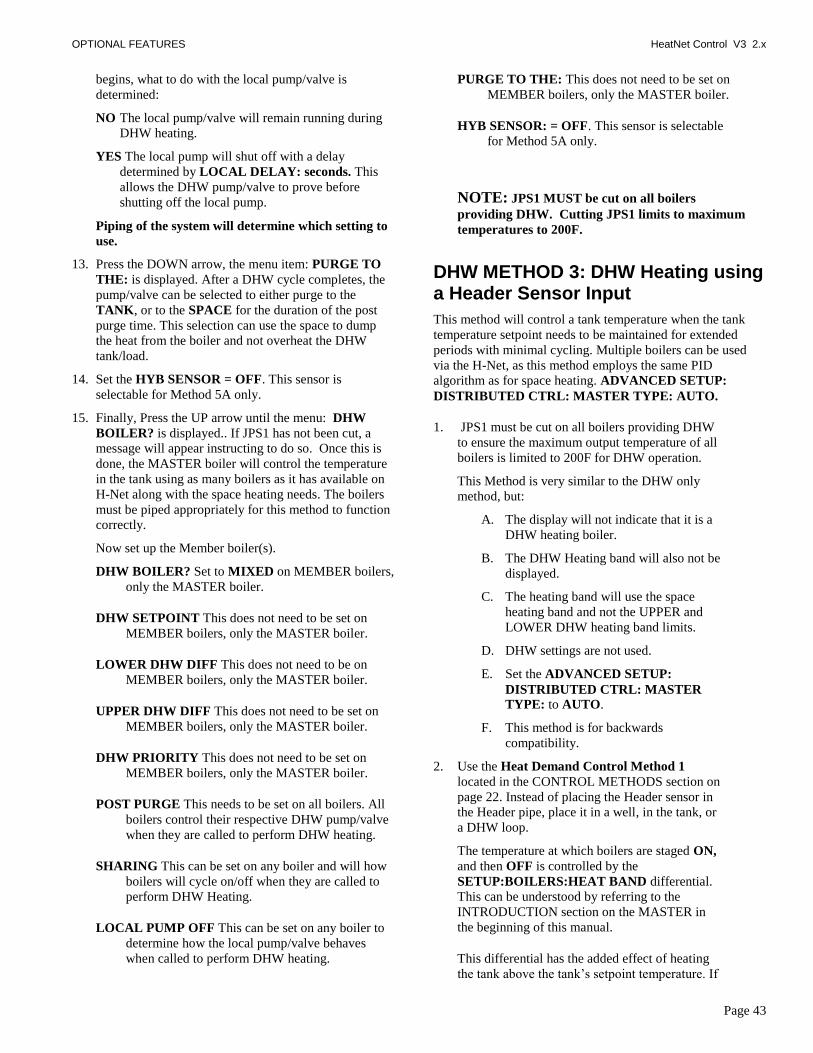
OPTIONAL FEATURES HeatNet Control V3 2.x
Page 43
begins, what to do with the local pump/valve is
determined:
NO The local pump/valve will remain running during
DHW heating.
YES The local pump will shut off with a delay
determined by LOCAL DELAY: seconds. This
allows the DHW pump/valve to prove before
shutting off the local pump.
Piping of the system will determine which setting to
use.
13. Press the DOWN arrow, the menu item: PURGE TO
THE: is displayed. After a DHW cycle completes, the
pump/valve can be selected to either purge to the
TANK, or to the SPACE for the duration of the post
purge time. This selection can use the space to dump
the heat from the boiler and not overheat the DHW
tank/load.
14. Set the HYB SENSOR = OFF. This sensor is
selectable for Method 5A only.
15. Finally, Press the UP arrow until the menu: DHW
BOILER? is displayed.. If JPS1 has not been cut, a
message will appear instructing to do so. Once this is
done, the MASTER boiler will control the temperature
in the tank using as many boilers as it has available on
H-Net along with the space heating needs. The boilers
must be piped appropriately for this method to function
correctly.
Now set up the Member boiler(s).
DHW BOILER? Set to MIXED on MEMBER boilers,
only the MASTER boiler.
DHW SETPOINT This does not need to be set on
MEMBER boilers, only the MASTER boiler.
LOWER DHW DIFF This does not need to be on
MEMBER boilers, only the MASTER boiler.
UPPER DHW DIFF This does not need to be set on
MEMBER boilers, only the MASTER boiler.
DHW PRIORITY This does not need to be set on
MEMBER boilers, only the MASTER boiler.
POST PURGE This needs to be set on all boilers. All
boilers control their respective DHW pump/valve
when they are called to perform DHW heating.
SHARING This can be set on any boiler and will how
boilers will cycle on/off when they are called to
perform DHW Heating.
LOCAL PUMP OFF This can be set on any boiler to
determine how the local pump/valve behaves
when called to perform DHW heating.
PURGE TO THE: This does not need to be set on
MEMBER boilers, only the MASTER boiler.
HYB SENSOR: = OFF. This sensor is selectable
for Method 5A only.
NOTE: JPS1 MUST be cut on all boilers
providing DHW. Cutting JPS1 limits to maximum
temperatures to 200F.
DHW METHOD 3: DHW Heating using a Header Sensor Input
This method will control a tank temperature when the tank
temperature setpoint needs to be maintained for extended
periods with minimal cycling. Multiple boilers can be used
via the H-Net, as this method employs the same PID
algorithm as for space heating. ADVANCED SETUP:
DISTRIBUTED CTRL: MASTER TYPE: AUTO.
1. JPS1 must be cut on all boilers providing DHW
to ensure the maximum output temperature of all
boilers is limited to 200F for DHW operation.
This Method is very similar to the DHW only
method, but:
A. The display will not indicate that it is a
DHW heating boiler.
B. The DHW Heating band will also not be
displayed.
C. The heating band will use the space
heating band and not the UPPER and
LOWER DHW heating band limits.
D. DHW settings are not used.
E. Set the ADVANCED SETUP:
DISTRIBUTED CTRL: MASTER
TYPE: to AUTO.
F. This method is for backwards
compatibility.
2. Use the Heat Demand Control Method 1
located in the CONTROL METHODS section on
page 22. Instead of placing the Header sensor in
the Header pipe, place it in a well, in the tank, or
a DHW loop.
The temperature at which boilers are staged ON,
and then OFF is controlled by the
SETUP:BOILERS:HEAT BAND differential.
This can be understood by referring to the
INTRODUCTION section on the MASTER in
the beginning of this manual.
This differential has the added effect of heating
the tank above the tank‘s setpoint temperature. If
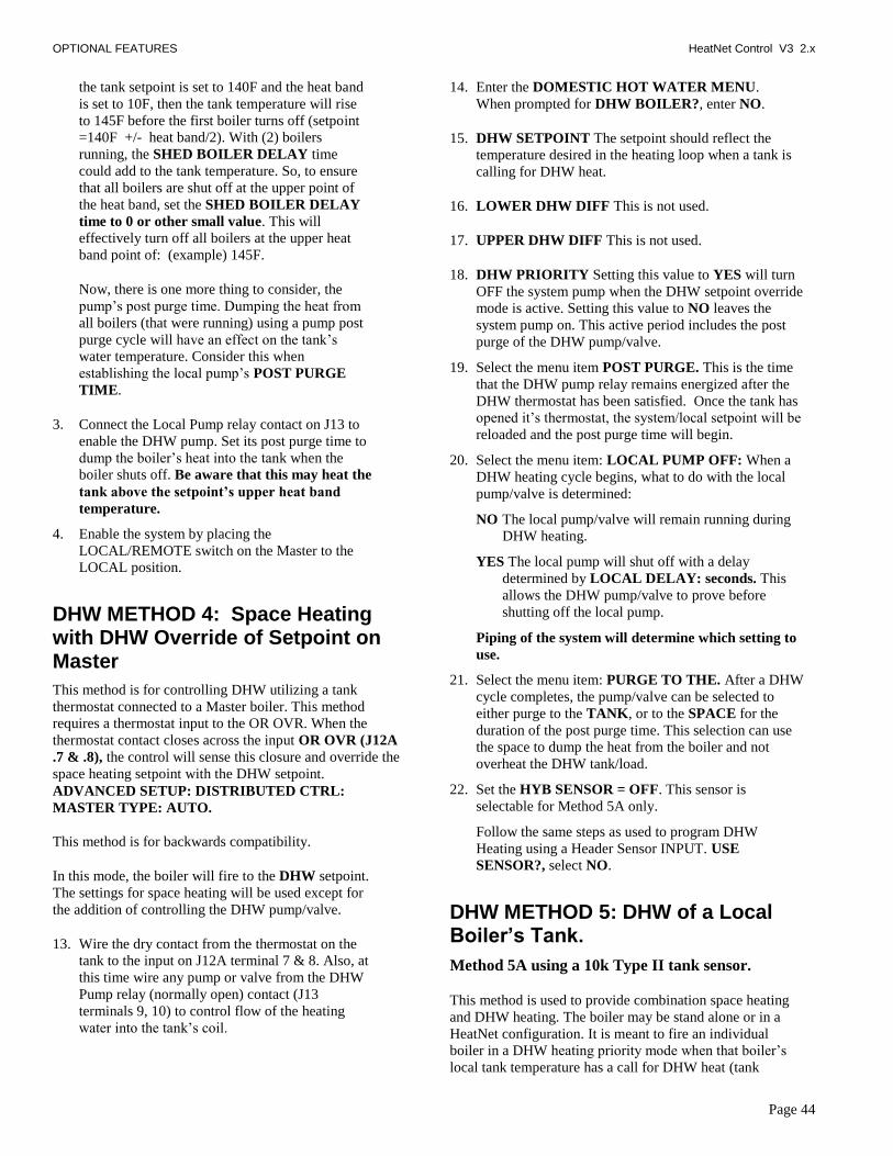
OPTIONAL FEATURES HeatNet Control V3 2.x
Page 44
the tank setpoint is set to 140F and the heat band
is set to 10F, then the tank temperature will rise
to 145F before the first boiler turns off (setpoint
=140F +/- heat band/2). With (2) boilers
running, the SHED BOILER DELAY time
could add to the tank temperature. So, to ensure
that all boilers are shut off at the upper point of
the heat band, set the SHED BOILER DELAY
time to 0 or other small value. This will
effectively turn off all boilers at the upper heat
band point of: (example) 145F.
Now, there is one more thing to consider, the
pump‘s post purge time. Dumping the heat from
all boilers (that were running) using a pump post
purge cycle will have an effect on the tank‘s
water temperature. Consider this when
establishing the local pump‘s POST PURGE
TIME.
3. Connect the Local Pump relay contact on J13 to
enable the DHW pump. Set its post purge time to
dump the boiler‘s heat into the tank when the
boiler shuts off. Be aware that this may heat the
tank above the setpoint‟s upper heat band
temperature.
4. Enable the system by placing the
LOCAL/REMOTE switch on the Master to the
LOCAL position.
DHW METHOD 4: Space Heating with DHW Override of Setpoint on Master
This method is for controlling DHW utilizing a tank
thermostat connected to a Master boiler. This method
requires a thermostat input to the OR OVR. When the
thermostat contact closes across the input OR OVR (J12A
.7 & .8), the control will sense this closure and override the
space heating setpoint with the DHW setpoint.
ADVANCED SETUP: DISTRIBUTED CTRL:
MASTER TYPE: AUTO.
This method is for backwards compatibility.
In this mode, the boiler will fire to the DHW setpoint.
The settings for space heating will be used except for
the addition of controlling the DHW pump/valve.
13. Wire the dry contact from the thermostat on the
tank to the input on J12A terminal 7 & 8. Also, at
this time wire any pump or valve from the DHW
Pump relay (normally open) contact (J13
terminals 9, 10) to control flow of the heating
water into the tank‘s coil.
14. Enter the DOMESTIC HOT WATER MENU.
When prompted for DHW BOILER?, enter NO.
15. DHW SETPOINT The setpoint should reflect the
temperature desired in the heating loop when a tank is
calling for DHW heat.
16. LOWER DHW DIFF This is not used.
17. UPPER DHW DIFF This is not used.
18. DHW PRIORITY Setting this value to YES will turn
OFF the system pump when the DHW setpoint override
mode is active. Setting this value to NO leaves the
system pump on. This active period includes the post
purge of the DHW pump/valve.
19. Select the menu item POST PURGE. This is the time
that the DHW pump relay remains energized after the
DHW thermostat has been satisfied. Once the tank has
opened it‘s thermostat, the system/local setpoint will be
reloaded and the post purge time will begin.
20. Select the menu item: LOCAL PUMP OFF: When a
DHW heating cycle begins, what to do with the local
pump/valve is determined:
NO The local pump/valve will remain running during
DHW heating.
YES The local pump will shut off with a delay
determined by LOCAL DELAY: seconds. This
allows the DHW pump/valve to prove before
shutting off the local pump.
Piping of the system will determine which setting to
use.
21. Select the menu item: PURGE TO THE. After a DHW
cycle completes, the pump/valve can be selected to
either purge to the TANK, or to the SPACE for the
duration of the post purge time. This selection can use
the space to dump the heat from the boiler and not
overheat the DHW tank/load.
22. Set the HYB SENSOR = OFF. This sensor is
selectable for Method 5A only.
Follow the same steps as used to program DHW
Heating using a Header Sensor INPUT. USE
SENSOR?, select NO.
DHW METHOD 5: DHW of a Local Boiler’s Tank.
Method 5A using a 10k Type II tank sensor.
This method is used to provide combination space heating
and DHW heating. The boiler may be stand alone or in a
HeatNet configuration. It is meant to fire an individual
boiler in a DHW heating priority mode when that boiler‘s
local tank temperature has a call for DHW heat (tank

OPTIONAL FEATURES HeatNet Control V3 2.x
Page 45
sensor‘s temperature drops below the DHW Setpoint +
Lower Diff). The boiler will stop space heating (if running)
and switch to DHW heating. The DHW pump/valve will be
engaged and the water temperature in the tank will be
maintained by the boiler at the DHW setpoint. Once the tank
temperature exceeds the Setpoint + Upper Diff temperature,
DHW heating will stop and the pump/valve‘s post purge
will start.
LOCAL DHW TANK
MEMBER
Tank Sensor
LOCAL DHW TANK
MASTER
Tank Sensor
Main Heating Loop
LOCAL LOCAL
DHW DHW
LOCAL DHW Simplified Drawing
When a tank‘s temperature sensor is connected directly to a
boiler and the DHW BOILER? is set to LOCAL. The
boiler will go offline from HeatNet and service the DHW
needs of its local tank. If the boiler is running in space
heating mode, then the ―SHARING?‖ setting may be used
to determine how, or if, to shut down before starting a DHW
cycle. When the DHW cycle is complete (includes the post
purge time of the DHW pump), the boiler will go back
online with HeatNet and become available to fire.
During a DHW cycle the DHW setpoint will be loaded
along with the UPPER and LOWER DHW DIFF. Also, the
ADVANCED SETUP: DISTRIBUTED CTRL:
MASTER TYPE: is set to AUTO.
When a 10k Type II sensor is used with this method, the OR
OVR input functions as and enable/disable. This allows the
DHW heating function to be enabled or disabled much in
the same way as the Heat Demand input for space heating.
When using this method, a DHW band is also available by
scrolling through the status screens. Press the DOWN arrow
key when SYSTEM SET is displayed. The space heating
band will be displayed on the left and the DHW Heating
band on the right. The bands will operate in a split screen
view.
23. Connect a 10k thermistor from the DHW tank‘s sensor
well to J10B terminals on any boiler. Wire a pump or
valve from the DHW pump or the System pump
(normally open) relay contact to control flow of the
heating water into the tank‘s coil or system loop.
The System pump will always be enabled as long as the
Heat Demand input is closed and the SETUP:
DOMESTIC HOT WATER:DHW PRIORITY is set
to NO. The DHW pump will be enabled whenever
there is a DHW call for heat.
A DHW call for heat is when the DHW temperature is
below the (DHW SETPOINT – LOWER DHW DIFF)
or when the DHW temperature is below the (DHW
SETPOINT + UPPER DHW DIFF) and boilers are
firing. After a DHW call for heat ends:
A. The pump will remain on during a post purge
pump cycle until the post purge timer expires.
24. Next, enter the DOMESTIC HOT WATER menu on
the Master boiler. When prompted for DHW
BOILER?, enter LOCAL.
25. Change the DHW SETPOINT to the desired target
temperature of the water in the tank. Once the control
determines there is a call for DHW, the DHW
SETPOINT is loaded and the boiler will target the
setpoint.
26. Now, change the DHW LOWER DIFF to the desired
temperature (DHW SETPOINT – LOWER DHW
DIFF) below which boilers are to be added. This setting
corresponds to the minimum water temperature
required in the tank. DHW heating will be initiated
when the DHW tank‘s water temperature is below the
temperature (DHW SETPOINT – LOWER DHW
DIFF).
How long the temperature of the tank stays below the
temperature (DHW SETPOINT – LOWER DHW
DIFF)) is used to determine when boilers are started
along with the ADD BOILER DELAY TIME.
27. Next, change the DHW UPPER DIFF to the desired
temperature (DHW SETPOINT + UPPER DHW DIFF)
above which boilers are to be shed. This setting is the
maximum tank temperature. Setting the SHED
BOILER DELAY TIME correctly will limit the
maximum tank temperature to the (DHW SETPOINT +
UPPER DHW DIFF). Setting the SHED BOILER
DELAY TIME = 0 will shut off all boilers immediately
once the (DHW SETPOINT + UPPER DHW DIFF) is
exceeded.
28. Press the DOWN arrow key again to position the
cursor beside the menu item DHW PRIORITY?.
Setting this value to YES will turn OFF the
system pump when the DHW mode is active
(when the DHW pump is on). Setting this value
to NO leaves the system pump on.
29. Press the DOWN arrow again and the menu item
POST PURGE should appear. This is the time
that the DHW pump relay remains energized after
the DHW SETPOINT has been satisfied.
A. The pump will remain on during a post
purge pump cycle until the post purge timer
expires.
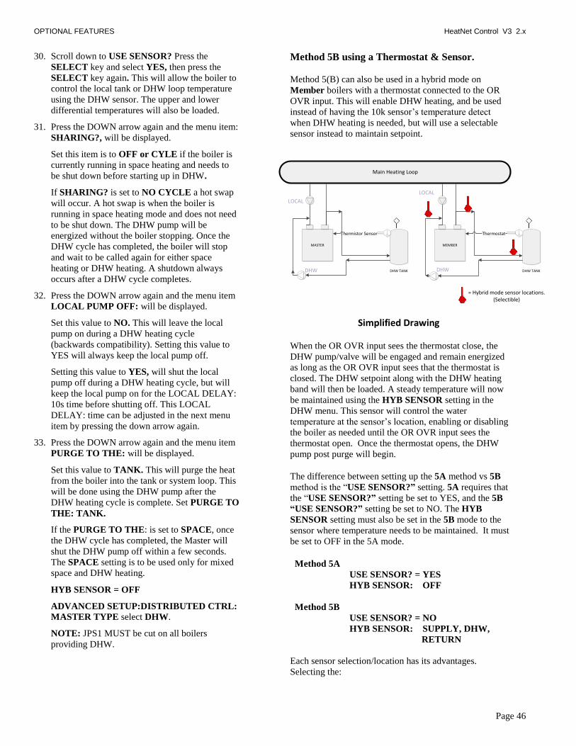
OPTIONAL FEATURES HeatNet Control V3 2.x
Page 46
30. Scroll down to USE SENSOR? Press the
SELECT key and select YES, then press the
SELECT key again. This will allow the boiler to
control the local tank or DHW loop temperature
using the DHW sensor. The upper and lower
differential temperatures will also be loaded.
31. Press the DOWN arrow again and the menu item:
SHARING?, will be displayed.
Set this item is to OFF or CYLE if the boiler is
currently running in space heating and needs to
be shut down before starting up in DHW.
If SHARING? is set to NO CYCLE a hot swap
will occur. A hot swap is when the boiler is
running in space heating mode and does not need
to be shut down. The DHW pump will be
energized without the boiler stopping. Once the
DHW cycle has completed, the boiler will stop
and wait to be called again for either space
heating or DHW heating. A shutdown always
occurs after a DHW cycle completes.
32. Press the DOWN arrow again and the menu item
LOCAL PUMP OFF: will be displayed.
Set this value to NO. This will leave the local
pump on during a DHW heating cycle
(backwards compatibility). Setting this value to
YES will always keep the local pump off.
Setting this value to YES, will shut the local
pump off during a DHW heating cycle, but will
keep the local pump on for the LOCAL DELAY:
10s time before shutting off. This LOCAL
DELAY: time can be adjusted in the next menu
item by pressing the down arrow again.
33. Press the DOWN arrow again and the menu item
PURGE TO THE: will be displayed.
Set this value to TANK. This will purge the heat
from the boiler into the tank or system loop. This
will be done using the DHW pump after the
DHW heating cycle is complete. Set PURGE TO
THE: TANK.
If the PURGE TO THE: is set to SPACE, once
the DHW cycle has completed, the Master will
shut the DHW pump off within a few seconds.
The SPACE setting is to be used only for mixed
space and DHW heating.
HYB SENSOR = OFF
ADVANCED SETUP:DISTRIBUTED CTRL:
MASTER TYPE select DHW.
NOTE: JPS1 MUST be cut on all boilers
providing DHW.
Method 5B using a Thermostat & Sensor.
Method 5(B) can also be used in a hybrid mode on
Member boilers with a thermostat connected to the OR
OVR input. This will enable DHW heating, and be used
instead of having the 10k sensor‘s temperature detect
when DHW heating is needed, but will use a selectable
sensor instead to maintain setpoint.
DHW TANK
MEMBER
Thermostat
DHW TANK
MASTER
Thermistor Sensor
Main Heating Loop
LOCAL
LOCAL
DHW DHW
= Hybrid mode sensor locations.(Selectible)
Simplified Drawing
When the OR OVR input sees the thermostat close, the
DHW pump/valve will be engaged and remain energized
as long as the OR OVR input sees that the thermostat is
closed. The DHW setpoint along with the DHW heating
band will then be loaded. A steady temperature will now
be maintained using the HYB SENSOR setting in the
DHW menu. This sensor will control the water
temperature at the sensor‘s location, enabling or disabling
the boiler as needed until the OR OVR input sees the
thermostat open. Once the thermostat opens, the DHW
pump post purge will begin.
The difference between setting up the 5A method vs 5B
method is the ―USE SENSOR?” setting. 5A requires that
the ―USE SENSOR?” setting be set to YES, and the 5B
“USE SENSOR?” setting be set to NO. The HYB
SENSOR setting must also be set in the 5B mode to the
sensor where temperature needs to be maintained. It must
be set to OFF in the 5A mode.
Method 5A
USE SENSOR? = YES
HYB SENSOR: OFF
Method 5B
USE SENSOR? = NO
HYB SENSOR: SUPPLY, DHW,
RETURN
Each sensor selection/location has its advantages.
Selecting the:

OPTIONAL FEATURES HeatNet Control V3 2.x
Page 47
Supply sensor will limit the temperature/firing rate of the
boiler, but may not be sufficient for continuous demand or
speed in heating the tank. It is already available, so no
additional sensor is needed.
Return sensor will allow the boiler to run its supply
temperature up quickly, but may bounce off of the
operating limit band. This would heat the tank in the
shortest time, but may overheat the tank. It is already
available, so no additional sensor is needed.
DHW sensor will allow the placement anywhere needed
to maintain that locations temperature. This is an
additional sensor that needs to be acquired.
A thermostat can be placed in a tank and connected to the
OR OVR input. (On Member boilers only, The Master
uses OR OVR already with DHW METHOD 4), When
the thermostat contact closes across the input OR OVR
(J12A .7 & .8) on a Member boiler, the control will sense
this closure and disconnect itself from HeatNet.
DHW METHOD 6: DHW using Direct Control
If the control‘s 4-20mA input is set to HIGH PRIORITY the
4-20mA signal, once brought above the 4-20mA starting
current can be used to override any other Heat Demand and
direct modulate the boiler.
This can be set in menu: ADVANCED SETUP:4-20mA
INPUT. It allows a member boiler to be taken offline and
directly modulated by an external control.
If the Master is using it for heating and the 4-20mA is set to
HIGH PRIORITY, an external control can now output a 4-
20mA signal which will take over the boiler‘s fire rate and
override all other heating demand inputs. The external control
would also need to open any valves/ or pumps This is
typically used for DHW control.

OPTIONAL FEATURES HeatNet Control V3 2.x
Page 48
Wiring Connections
Figure 28 Dip Switches and Wiring
Wire Strip Length.
If the terminal blocks are of the screwless type, the wire should be stripped to .42” or
10.67mm.
If the terminal blocks are of the screw type, the wire should be stripped to .25” or 6.34mm.
4-20mA Input select, See: Figure 32
Factory:JP2 = 2-3
P3:No Shunt
Boot Loc 0
JS1: Shunt 1-2 = 0-10VDCShunt 2-3 = 4-20mA
J4.1 &.5
Modbus & HeatNet
Termination. See: Figures 33
& 30
S5 SETTINGS
4-20mA 1 135 OHM ENABLE
OFF 2 ENABLE
NONE 3 10K STACK
NONE 4 PLATINUM STACK
J4.3-J4.7, PWM 5 J4.3-J4.7, 0-10V
J4.1-J4.5, PWM 6 J4.1-J4.5, 0-10V
BLOWER PWM 7 BLOWER 0-10/20V
PROG USB CHIPNORMAL USB 8
Typical Settings for KN30:
S5 Dip switches 1,5,7,8 set the Outputs of the J4 Connector.S5.1) Set to position 4-20mA for J4.1+ and J4.5- 4-20mA current mode (JS1 = 4-20mA).
Set to position 135 Ohm for J4.1(W), J4.7(B), and J4.5® 135 Ohm mode (JS1 = 4-20mA).NOTE: S5.6 must be set to J4.1-J4.5, 0-10V for the above to work in 4-20mA mode
If JS1 is set to 0-10VDC then this switch has no effect on J4.1 and J4.5.S5.2) NOT USED (Factory)S5.3) Set to NONE if there is no Stack Sensor or if a 1k Platinum stack sensor is used.
Set to 10k STACK, if a 10k Thermistor stack sensor is connected to J10B.S5.4) Set to NONE if there is no Stack Sensor or if a 10k Thermistor stack sensor is used.
Set to PLATINUM STACK, if a 1k Platinum stack sensor is connected to J10B.
S5.5) Set to J4.3-J4.7, PWM, Configures J4.3+ and J4.8- for PWM outputSet to J4.3-J4.7, 0-10V, Configures J4.3+ and J4.8- for 0-10 VDC output
S5.6) Set to J4.1-J4.5, PWM, Configures J4.1+ and J4.5- for PWM output (JS1 = 0-10VDC).Set to J4.1-J4.5, 0-10V, Configures J4.1+ and J4.5- for 0-10 VDC or 4-20mA output (JS1 = 4-20mA or 0-10VDC). This switch in conjuction with S5.1
S5.7) Set to BLOWER PWM for Ametek Blowers.Set to BLOWER 0-10/20V for VFD controlled blowers.
S5.8) Set to NORMAL USB = Normal operationSet to PROG USB CHIP (FACTORY ONLY)

WIRING CONNECTIONS HeatNet Control V3 2.x
Page 49
Figure 29 Heating Method 1 H-Net, Master/member
MO
DB
US
RJ45 HeatNet In and Out
3 wire Shielded HeatNet In and Out
HeatNet Boiler to Boiler
Communications
HeatNet Termination.Enable: Switches DOWN Position.Disable: Switches UP position.Switch shown disabled.
MEMBER: Close to run at Local setpoint.MASTER: Close to control all boilers and run at System setpoint. Close this contact to override the outdoor
reset slope and run boiler at the Local setpoint.
The (2) LEDs on the RJ45 indicate:GREEN: Transmit Data
YELLOW: Received Data
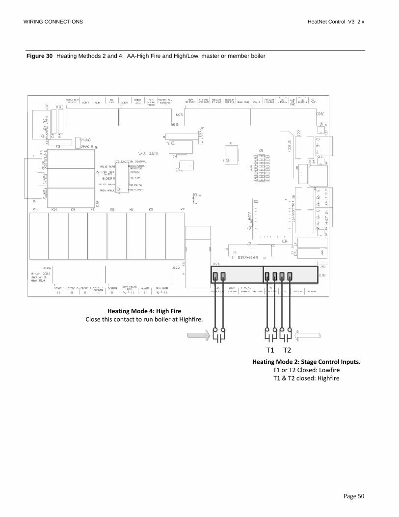
WIRING CONNECTIONS HeatNet Control V3 2.x
Page 50
Figure 30 Heating Methods 2 and 4: AA-High Fire and High/Low, master or member boiler
Heating Mode 2: Stage Control Inputs.T1 or T2 Closed: LowfireT1 & T2 closed: Highfire
T1 T2
Heating Mode 4: High FireClose this contact to run boiler at Highfire.

WIRING CONNECTIONS HeatNet Control V3 2.x
Page 51
Figure 31 Heating Method 3 4–20 ma/ 0-10 VDC
Closing this contact enables the 4-20 mA/0-10 VDC input on channel 1
Channel 1:4-20mA/0-10VDC
Channel 2:4-20mA/0-10VDC(+)
24 VDC
(+)(-)
(-)
24 VDC Return
This Method allows direct modulation of the boiler based on a 4-20 mA control signal. A control capable of transmitting a 4-20mA/0-10 VDC control signal for the purpose of modulating a boiler and to control a common system temperature must be used with this method.
NOTE: If using a 0-10 VDC signal multiply any references to current in the manual by .5. Example: 5ma * .5 = 2.5 VDC
S6 along with the SETUP:ADVANCED:4-20mA INPUT menu configures the channel for operation.
S6 switch 1 DOWN: 4-20mA channel 1S6 switch 1 UP: 0-10VDC channel 1
S6 switch 2 DOWN: 4-20mA channel 2S6 switch 2 UP: 0-10VDC channel 2
1
2

WIRING CONNECTIONS HeatNet Control V3 2.x
Page 52
Figure 32 Heating Method 5: MODBUS (Optional BACnet or LonWorks bridge — Protocessor)
3 wire Shielded Modbus
Modbus Termination.Enable: Switches DOWN Position.Disable: Switches UP position.Switch shown disabled.
Protocessor Bridge Module Plug-in.LonWorks or BACnet bridge whichCan be used instead of the MODBUS input.
Shielded/Twisted Pair Connection (MSTP/LonWorks)
RJ45 Configuration and IP connection
NOTE: Do not plug the Protocessor module in with power on or the Protocessor module may be damaged.
The pin headers are located on the control (‘U’ shaped) that the Protocessor bridge module plugs in directly. Align the sockets on the Protocessor with the pin headers on the control, then press into place. Communication from the Protocessor bridge to the H-Net control is also handled through the sockets.
Next, connect the BACnet or LonWorks network cable to the Protocessor module or configure the bridge using the software tools. Once connected use the DIP switch to enable termination.
RJ45 Cat 5 Modbus
Additional Bulletins and Instructions for Configuring BACnet or LonWorks are available on the website.
DIP Switch shown:NOT Terminated
The (2) LEDs on the RJ45 indicate:GREEN: Transmit Data
YELLOW: Received Data

WIRING CONNECTIONS HeatNet Control V3 2.x
Page 53
Figure 33 Relays, Interlocks and Boiler Status
The Highest priority
Low Voltage Interlocks, 24VAC
Factory ------------------------------
Water Flow Switch-----------------
Operator------------------------------
Spare for user or Factory ------
Gas Pressure (High & Low) -----
Variable Frequency Drive--------
Low Water Cutoff-------------------
SYSTEM FLOW PROVE --------- 1
2
3
4
5
6
7
8
Low Fire Hold: Fires the boiler at the minimum rate while in Calibrate. This functions exactly as the T1 input
Calibrate: Allows adjustment of the Minimum Fire, Maximum Fire, and Pilot Ignition settings.
Combustion proving switch from Combustion Air Damper.
Remote 120 VAC Operator USB and Flashdrive Ports:
Used by HeatNet Pro and updating firmware.
Local Pump orPower Open/ Power Close Valve
DHW Pump orPower Open/ Power Close Valve
Stage Control
Damper Control Alarm
JUMPER WIRE if not used

WIRING CONNECTIONS HeatNet Control V3 2.x
Page 54
Figure 34 Temperature sensors
T
T
T
T
T
All Temperature Sensors are 10k Thermistors.Immersion sensors require a well.
(OPTIONAL) Water Temperature Common System Supply (Header)
(REQUIRED) Water Temperature OUT (supply) of Boiler
(REQUIRED) Water Temperature INLET (return) of Boiler
IF CONNECTED, BOILER = MASTER
(OPTIONAL) Outside Air Temperature Sensor
(OPTIONAL) DHW Temperature Domestic Hot Water Temperature (TANK)
T (OPTIONAL) Stack Temperature
T(OPTIONAL) System Return Temperature
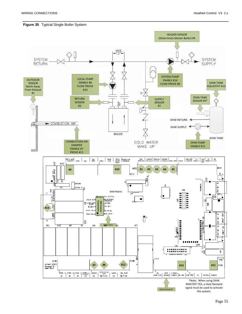
WIRING CONNECTIONS HeatNet Control V3 2.x
Page 55
Figure 35 Typical Single Boiler System
#4#3#2#1
#8
#14
#7 #11
#9 #10 #5
#13#12
IGN
Co
ntro
lC
on
ne
ction
s
High Limit
Heat Demand*
*Note: When using DHW MASTER? YES, a Heat Demand signal must be used to activate
the system.
HEADER SENSOR(Determines Master Boiler) #4
RETURN SENSOR
#3
SUPPLY SENSOR
#2
LOCAL PUMPENABLE #8
FLOW PROVE #10
SYSTEM PUMPENABLE #14
FLOW PROVE #9
OUTDOOR SENSOR
North Away From Exhaust
#1
BOILER
DHW TANK
DHW PUMPENABLE #12
DHW TANK SENSOR #5*
DHW TANK AQUASTAT #13
DHW RETURN
DHW SUPPLY
COMBUSTION AIR DAMPER
ENABLE #7PROVE #11

WIRING CONNECTIONS HeatNet Control V3 2.x
Page 56
Figure 36 Using a 4–20ma signal for direct modulation
100%
Boiler Output
0%
Boiler Off
Ignition
100%0%Percent of Boilers
Output
Percent of Boilers
OUTPUT
Ignition
4mA 20mA
Control Signal
Output Range From
ControlNo Effect
Once boiler starts the
control signal must
drop below 4.01 mA
to stop Boiler
MAX
OUTPUT
After Ignition
0% 100%
Control Signal to MAX Output
Boiler Off
Percent of Boilers
INPUT
0ma
Display input % of control when running
A control signal greater
than 4.2mA (adjustable)
will start boiler.
PWM Duty Cycle
Blower Off
20%
Blower Fully ON
80% 100%0%
20% = the
minimum speed
the VFD will run
20% for 5:1 boilers
25% for 4:1 boilers
33% for 3:1 boilers
33%
20%
25%
33%
20%
25%
20% for 5:1 boilers
25% for 4:1 boilers
33% for 3:1 boilers
Boiler Off

WIRING CONNECTIONS HeatNet Control V3 2.x
Page 57
Figure 37 Common system damper wiring
DAMPER
24 VAC RetDAMPER 24 VAC
Transformer
DAMPERProve Switch
DAMPEREnable
24 VAC
Mains
MASTER BOILER
MEMBER BOILER 1Connection if Member
boiler is running as Failsafe
MEMBER BOILER 2
Connect to 24 VAC Return on each Boiler
NOTE: Ensure that the Combustion Air
Damper is enabled on all Boilers for use. SETUP MENU:AUX FUNCTIONS

WIRING CONNECTIONS HeatNet Control V3 2.x
Page 58
Figure 38 Failsafe common system pump wiring
System Pump Contactor
System Pump Voltage Feed
System Pump
System Pump Voltage Return
120VAC
Ph2
Ph3
120 Return
120 VAC Return
DPST Relay
System Flow Prove Switch
120VAC
Add additional relays/contacts for more boilers
MASTER BOILER
MEMBER BOILER 1

Calibration HeatNet Control V3 1.x
Page 59
Calibration
The calibration of the KN-Series boiler
should only be performed by a
licensed technician.
To enter the calibration menus, place the S2 switch on the
main control board to the CAL position.
Be sure to set this switch back to NORM when the
calibration is complete, otherwise no external control inputs
will work (except T1-T2), the display will always indicate
CALIBRATE and some of the runtime temperatures will
not be displayed.
The MIN VFD setting, the MAX VFD setting, and the
Ignition setting can be adjusted in the calibration displays.
The values can be changed while running ONLY IN MINIMUM FIRE (any, but only one of the T inputs closed).
Prior to ignition, the values may be changed, but the blower
will not operate.
The Low Fire Hold switch is located near the Calibration switch.
Press the arrow keys until MIN VFD is shown in the
display, along with the minimum percentage value at which
the boiler is to run at min fire. While in Standby (no call for
heat on inputs), the minimum percent may be preset. To set
the minimum rate while running, any (1), and only (1) of the
(T) inputs must be closed in order to set the boiler to
MINIMUM fire. Press the SELECT key for approximately
1 second. The Percentage value will start flashing,
indicating that it can be adjusted. Adjust the Minimum value
to the desired setting using the arrow keys. The Minimum
setting is clamped to its lowest rated setting and cannot be
adjusted below this. Once you are done with this setting,
press the SELECT key until the value stops flashing. The
new setting is now saved.
Press the Arrow key to select the IGNITION percent. The
Blower speed will be set here to provide the rate for
ignition. While in Standby (no call for heat on inputs), the
Ignition percent may be preset, before firing the boiler. To
set the ignition rate while running, any (1), and only (1) of
the T inputs must be closed Pressing the SELECT key here
will cause the IGNITION setting to flash and the boiler will
ramp to the ignition setting. Adjust it using the arrow keys
and then press the SELECT key until the value stops
flashing. The new setting is now saved.

LOG ENTRY HeatNet Control V3 1.x
Page 60
Log Entry
The KN-Series H-Net control contains a log that records the
major activity (events) in the operation of the boiler. This
activity includes interlock faults, boiler starting and
stopping events, power cycles, misc. faults, and types of
calls-for-heat (control inputs). Setting the time clock to an
accurate time and date is very useful when events are
recorded, since the control will time stamp each snapshot. If
the system is configured to run with HeatNet, then only the
Master boilers SYSTEM TIME needs to be entered. The
Master will then set the time on all Member boilers.
The log is primarily used as a troubleshooting and
diagnostic tool, but may be used as a performance tool to
view run time cycles.
An event in time of the boiler‘s state is presented via
multiple screens. Each screen event can be stepped through
using the arrow keys.
The top line displays the time and date the event occurred.
In the top right corner, the event # is displayed so that easy
indexing can be done using the arrow keys. The second line
displays the Water temperature of the boiler‘s output
(supply) and the Setpoint temperature. The third line
displays the Outside Air temperature, and the Modulation.
The bottom line is used to record the control state of the
boiler.
The control state is defined as the Boiler(s) that is running,
the Circulator Pump state, and the ignition condition (Main
Valve, Pilot Valve, Blower, and the Ignition alarm). The #
of boilers that are displayed is limited to 7 if the boiler is the
MASTER. If boilers #8 and up need to be viewed, the
Boiler Control Pro software will need to be used. The Last
2 characters on the fourth line indicate the heating mode the
control is in. The modes are:
NC = No Call for Heat
HD = Heat Demand (MASTER and Local modulation
control using PID control, MASTER and
MEMBER)
RM = Remote Modulation from 4-20ma input
HF = High Fire from ALL T-inputs closed or the AA
input
1T = Low Fire from any 1 T-input closed (Low Fire or
High Fire)
2T = Mid Fire from any 2 T-inputs closed (Low fire or
High Fire )
OP = Option input Active
HT = H-Net Control using the Heat-Link
communications cable
The bottom line is also used to indicate an interlock or limit
that has tripped. It may also indicate a sensor that has failed.
When this occurs, the normal bottom line in the display is
not visible, and the sensor fault is displayed.
For details on messages that appear on the fourth line: See
Appendix B.
The log may also be viewed using HeatNet Pro or HeatNet
Online.
Figure 39 Log entry display
Tim
e
Sta
mp
Eve
nt
num
be
r
Water Setpoint
Modulation PWM %
M = Main Valve open
P = Pilot Valve open B = Blower ON
P = Circulator Pump
Boiler 1 OnBoiler 2 On
Boiler 3 On
Outside Air
Temperature
NC = No Call for Heat
HD = Heat Demand
RM = Remote Mod 4-20ma
HF,1T, 2T, 3T = T-inputs Fire Rates
HT = H-NET Control
H= Honeywell Alarm
Boiler 7
S = System Pump
D = DHW Pump (Ver 2.x control)
SET: 0 5 : 4 2 P
H2O 1 2 7 ° FMOD%
1
3 1 0 / 1 4 1 3
OA 6 5 ° F1 4 0 ° F
5 7P- - - - - - H HDMPB

DEFAULT SETTINGS & MENU ITEM DESCRIPTIONS HeatNet Control V3 2.x
Page 61
Default Settings & Menu Item Descriptions — SETUP
MENU DEFAULT
VALUE RANGE DESCRIPTION
BOILERS
# OF BOILERS 1 (1-16) If operating as a member.
LEAD BOILER # 0 (0-16) # of first boiler to run, determines the fire order in rotation. A
LEAD BOILER # 0 (0-16) # of first boiler to run, determines the fire order in rotation. A 0
disables the Lead Boiler function. Firing Mode determines lead.
HEAT BAND 30F (2 -50 F) Differential temp around setpoint used to stage boiler(s) OFF/ON
HNT M (M-16) This line displays the boilers auto detected by H-Net. While M is the
Master boiler the numbers are the H-Net address of each boiler from
2–16.
SETPOINTS
LOCAL SETPT 160 F (40-220 °F) Local setpoint used to maintain temperature of SETPT SOURCE
OPERATE LIMIT 215 F (45-230 °F)
When running as a member, boiler shuts off when supply
temperature reached.
Boiler restarts at lower temp of OP LIM BAND or 10F whichever is
lower
LOCAL SETPT 160 F (40-220 F) Local setpoint used to maintain temperature of SETPT SOURCE
OP LIM BAND 20F (1-50 F) Limits external input % when in (OP LIM - OP LIM BAND)
SETPT SOURCE AUTO AUTO
4-20mA
AUTO = Local/ System/ WWS Setpoint is used
4-20mA input is mapped to a setpoint.
OUTDOOR AIR RESET
OA RESET OFF Outdoor reset ratio (boiler water temp/outside air temp).
WARM WEATHER SD NO If set to YES, the boiler /system shuts down when the temperature
exceeds the WWS SETPOINT.
WWS SETPOINT 68F (40 – 100 F)
Temperature at which boiler shuts down, operation is below this.
If boiler is running using either OA RESET or WWS and the OR
OVR input is closed the OA RESET slope is overridden and runs at
local setpoint until OR OVR input opens.
SET OA SETPOINTS
WATER TEMP At HIGH OA TEMP
140F (60 – 190 F) Boiler water temp setpoint when OA temp is at HIGH OATEMP
These four setpoints determine the OA reset slope.
WATER TEMP At LOW OA TEMP
10F (-35 – 40 F) Header/Supply setpoint when OA Temp is at LOW OA TEMP
PUMP OPTIONS
SYSTEM PUMP
POST PRGE TIME 2 minutes (2-60min) Time in minutes to keep system circ. pump on after boiler stops
PUMP ROTATION New menu screen
ROTATION: NONE NONE
SYS HRS PUMP HRS
SYSTEM PUMPS 1 1 or 2 The number of system pumps connected.
ROTATE TIME 240 hrs 1-1000 hrs
If ROTATION is set to SYS HRS, ROTATE TIME is used to switch
pumps when this time expires. This time is measured against the
actual time the system pump is enabled. This would include a post
purge time.

DEFAULT SETTINGS & MENU ITEM DESCRIPTIONS HeatNet Control V3 2.x
Page 62
If ROTATION is set to PUMP HRS, ROTATE TIME is used to
switch pumps when the pump‘s time difference is greater than
ROTATE TIME. Whichever pump has the least time and is at least
below the other (pump‘s time - ROTATE TIME) will switch to the
enabled state. This selection is used to equalize run time on the
pumps.
MORE MENUS New menu screen follows.
ZERO RUNTIME PUMP1 PUMP1- PUMP2
This menu allows the clearing of a pump‘s runtime counter.
Discretion is advised in clearing only one pump‘s hours after
replacement and then using ROTATION set to PUMP HRS. This
would cause the pump whose runtime was cleared to run until it‘s
time exceeded the other older pump.
PUMP1 TIME 0-999999 hrs Indicates how many hours the HeatNet control has accumulated on
pump 1.
PUMP2 TIME 0-999999 hrs Indicates how many hours the HeatNet control has accumulated on
pump 2.
ALWAYS ENABLED OFF ON/OFF ON = Pump never shuts off. Used when there is only 1 system pump
in the system.
SUMMER PUMP JOG OFF ON/OFF
MON-SUN
Used with Outdoor Reset, Jogs the local and system pump(s) for
POST PRGE time when system is in summer shutdown. Jog once a
week @12:00 AM.
The menu item OVR ENAB IN WWS and ALWAYS ENABLED
must be set to OFF for the jog function to work,
OVR ENAB IN WWS OFF ON/OFF
Priority mode for the system pump while in Warm Weather
Shutdown. ON: The system pump is allowed to run in WWS when
the OR OVR override input is closed. When set to OFF, the system
pump will not come on while in WWS with the OR OVR override
input closed. Enabling this feature disables the SUMMER PUMP
JOG.
LOCAL PUMP
DELTA TEMP ENAB OFF ON: Use Delta temperature to shut pump off when temperature
across boiler is less than DELTA TEMP setting.
DELTA TEMP 10 °F (2 – 50 F)
POST PRGE TIME 2 minutes (1-60min) Time in minutes to keep local circ. pump on after boiler stops
ALWAYS ENABLED OFF Pump never shuts off.
PUMP/VALVE OPTIONS
MASTER PUMP/VALVE
REMAINS ON: OFF ON/OFF ON: The master boiler will keep its pump/valve on when no boilers
are running. Prevents deadheading the system flow.
LOCAL PUMP VFD OFF ON/OFF
ON: Outputs a 0-10VDC or 4-20mA signal from J4 pins 1 & 5 that is
proportional to the fire rate of the boiler. Connect to a VFD
controlling a Local pump.
FLOW PROVE 10s 10-240 sec This is an adjustable flow proving time to allow slower valves to
open before proving flow.
NIGHT SETBACK
SETBACK ENTRY 1 (1 – 4) Four setbacks to adjust setpoint during a time period
ENTRY IS OFF Enable or disable the use of this setback
SETBACK 20 F (0 – 50 F) Temporarily subtracts this temp from the setpoint
START DAY MON Day of the week to begin setback or a day range
TIME 12:00AM Time to begin setback
END DAY MON Day of the week to end the setback or a day range

DEFAULT SETTINGS & MENU ITEM DESCRIPTIONS HeatNet Control V3 2.x
Page 63
TIME 12:00AM Time of the day to end the setback
OPTIONS
TEMP SCALE F (F or C) Fahrenheit scale is default
KEY CLICK ON Beeps when a key is pressed
SKIP PASSWORD ON Disables the Password
BRIGHTNESS 50% (25, 50,75,100) Four levels of display brightness, lower for longer life of the display
LOG/RUNTIME
RUN HOURS Displays runtime hours. Total time the main valve has been open.
DATA LOG ENTRY Displays the current entry in the data log
SIZE Displays the current size of the log in entries
BOILER CYCLES Displays completed boiler cycles. Incremented when the main valve
turns OFF after it has been ON. Does not include attempts to light.
AUX FUNCTIONS
COMBUST AIR DAMPER
TYPE LINKED/COMMON
INDEPENDENT
The LINKED/COMMON setting allows one common damper to be
used and controlled by the Master Boiler. All Member boilers must
have their damper prove inputs wired as per Figure 37, Common
system damper wiring, page 57. Also see Section: Optional
Features: Auxiliary Function Options INDEPENDENT: Individual
dampers are in controlled by their respective boiler.
IN USE? YES
If set to YES, then OUTPUT RELAY K5 can be used to control a
combustion air damper. The Master can control a common system
damper or an individual damper. Members control their respective
damper independent of the Master. Relay K5 is used to enable the
combustion air damper. See Figure 37, Common system damper
wiring, page 57. Needs to Prove the damper is open.
INPUT: J12B.7
DAMPER
The damper prove input is dedicated to connect at J12B terminals 7
and 8. If using a common damper refer to the common damper
wiring diagram.
PROOF TIME 2:00 (0 – 4min)
This is the proving time in minutes for the combustion air damper
prove switch. It is sensed at J12B Pin 7. If the damper faults, a retry
will occur every 10 minutes in attempt to open the damper.
When using J12B in a common damper configuration, wiring is done
beginning with the Master boiler. J12B Pins 7,8 are connected to the
prove switch of the combustion damper. Pin 8 is supplying 24 VAC
and pin 7 is the sense input. A second wire is connected to J12B pin
7 of the Master and the other end connected to the first member
boilers J12B pin 7. If another member boiler is present, connect
another wire to the J12B Pin 7 terminal of the first member and the
other end to the second member boiler J12B pin 7. Continue this
method for each additional boiler.
ALARM SILENCE
ALARM SILENCE IN USE?
YES
This menu allows the configuration of the Alarm Silence switch. It
can be disabled so that the Alarm Silence switch cannot silence the
alarm until the alarm is cleared; ALARM SILENCE = NO. The
default value is to enable the ALARM SILENCE switch. Holding
down the BACK and SELECT keys at the same time may also be
used to silence the alarm.
INPUT = J10B STACK If a stack sensor is used, holding down the BACK and SELECT keys
at the same time is the only way to silence the alarm.
FAILSAFE MODES
RUN IN LOCAL IF: H-NET COMM LOST
OFF If this entry is set to ON and the Member boiler does not see any
communications coming from the Master boiler, this boiler will run

DEFAULT SETTINGS & MENU ITEM DESCRIPTIONS HeatNet Control V3 2.x
Page 64
in LOCAL. The boiler will continue to run in LOCAL until
communications are re-established or this entry is set to OFF.
LOW TEMP OFF
This entry may be set to one of the temperature sensors: SUPPLY,
HEADER, RETURN, or turned OFF (default). If this entry is set to a
sensor and the temperature falls below TEMP, the boiler will
automatically start and run the water temperature up to the LOCAL
Setpoint and then shut OFF.
TEMP < 40F 40 F 35-200 F This is the temperature that the selected sensor must fall below for
the boiler to start.
MENU DEFAULT
VALUE RANGE DESCRIPTION
HEAT EXCHANGER
ALARM TYPE FAULT FAULT/WARNING
FAULT will stop the boiler when the Delta T has exceeded its
setting.
WARNING will allow the boiler to continue running, but produce
the Warning message.
EXCHR DELTA T
AUTO
60 F
AUTO
1 to 120 F
Settings are AUTO if running DELTA HIGH/LOW protection.
This is the maximum differential temperature the heat exchanger can
see before the LIMIT RATE feature is activated, and a log entry is
made.
LIM-> HALF RATE NA
YES
Not Available when operating in DELTA HIGH/LOW protection.
Limit to Half Rate: When set to YES, and the maximum differential
temperature (delta T) has been exceeded, the fire rate called for is cut
in half. In other words: if we are calling for 80% modulation and
have exceeded the delta T, the boiler will only fire at 40%. The delta
T needs to drop 10F below the maximum delta T to reset this limit.
The message ― ½ INPUT‖ will be displayed on a member boiler and
a Master Boiler will display the Modulation % for the system even
though it is running at ½ of this rate. This method helps protect the
heat exchanger from damage due to excessive delta T‘s. If this
Master boiler is running
SEND RETURN RETURN RETURN, SYS RET
This setting is used by the Master boiler to select which Return
sensor temperature to send to all Member boilers. The Return
temperature will then be used by the Member boilers (usually non-
condensing) to determine if they can be called by the Master to run.
If a System Return sensor is available on the Master, set this setting
to SYS RET. If only a Return sensor is available, set to RETURN.
TEMP DISAB OFF SYS RET, RETURN,
OFF
This setting is used by a Member boiler (primarily a non-condensing
type) to determine which return sensor to look at when determining
if it is safe to fire. Its purpose is to keep non-condensing boilers from
firing in a condensing mode.
SYS RET the boiler will use the Return temperature sent from the
MASTER boiler.
RETURN the boiler will use its own Return sensor. If it is set to
OFF, then this feature will not be used.
If a sensor is selected, then the Boiler will determine if the Return
sensor‘s temperature is below the TEMP< XXX setting in the
following menu. If the Return temperature is lower, the boiler will
take itself offline from the Master. Informing the Master that it can
not run. The message ―blr offline” will be displayed in the Status
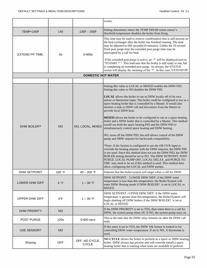
DEFAULT SETTINGS & MENU ITEM DESCRIPTIONS HeatNet Control V3 2.x
Page 65
screen.
TEMP<140F 140 135F – 200F Setting determines where the TEMP DISAB return sensor‘s
threshold temperature disables the boiler from firing.
EXTEND PP TIME: 0s 0-600s
This time may be used to remove condensation that is still present on
the heat exchanger after the boiler has finished running. The time
may be adjusted to 600 seconds(10 minutes). Unlike the 10 second
fixed post purge time the extended post purge time may be
interrupted by a call for heat.
If the extended post purge is active, an ‗*‘ will be displayed next to
―STANBY * ‖. This indicates that the boiler is still ready to run, but
is completing an extended post purge. As always, the STATUS
screen will display the meaning of the ‗*‘. In this case: EXTEND PP.
DOMESTIC HOT WATER
DHW BOILER? NO NO, LOCAL, MIXED
Setting this value to LOCAL or MIXED enables the DHW PID.
Setting this value to NO disables the DHW PID.
LOCAL allows the boiler to run in DHW locally off of its own
sensor or thermostat input. The boiler could be configured to run as a
space heating boiler that is controlled by a Master. It would also
monitor a tank or DHW call and disconnect from the Master to
provide local DHW heat.
MIXED allows the boiler to be configured to run as a space heating
boiler and a DHW boiler that is controlled by a Master. This method
would use both the space heating PID and the DHW PID to
simultaneously control space heating and DHW heating.
NO, turns off the DHW PID, but still allows control of the DHW
pump and DHW setpoint for backwards compatibility.
*Note: If the System is configured to use the OR OVR input to
override the heating setpoint with the DHW setpoint, the DHW PID
is not used. Since this method does not use the DHW PID, the DHW
BOILER setting should be set to NO. The DHW SETPOINT, POST
PURGE, LOCAL PUMP OFF, LOCAL DELAY, and PURGE TO
THE: may need to be set if this method is used. This method does
allow configuring the LOCAL and DHW pumps.
DHW SETPOINT 160 F 40 – 200 F Setpoint that the boiler/system will target when a call for DHW.
LOWER DHW DIFF 5 F 1 – 30 F
DHW SETPOINT – LOWER DHW DIFF: if the DHW water
temperature is less than this temperature, the Boiler/System will
enter DHW Heating mode if DHW BOILER? is set to LOCAL or
MIXED.
UPPER DHW DIFF 3F 1 – 30 F
DHW SETPOINT +UPPER DHW DIFF: if the DHW water
temperature is greater than this temperature, the Boiler/System will
begin shutting off DHW boilers if the DHW BOILER? is set to
LOCAL or MIXED
DHW PRIORITY NO If the DHW PRIORITY is set to YES, then when there is a call for
DHW, the system pump shuts off. If NO, the system pump stays on.
POST PURGE 120s 0-600 secs This is the time that the DHW relay remains on after the DHW call
ends.
USE SENSOR? NO
If this entry is set to YES, the DHW 10k Sensor is looked to for
controlling DHW water temperature. If set to NO, A thermostat is
used.
Sharing OFF OFF, NO CYCLE,
CYCLE
NO CYCLE allows the boiler to perform as a space or DHW heating
boiler. DHW always has priority and will override (steal) a space
heating boiler that is running when none are available to perform

DEFAULT SETTINGS & MENU ITEM DESCRIPTIONS HeatNet Control V3 2.x
Page 66
DHW heating. When this happens, the boiler will not shut down, but
keep running during the change from space heating to DHW (Hot
Swap). Once the DHW cycle completes, the boiler will shut down
and wait to be called for space heating again.
CYCLE allows the boiler to perform as a space or DHW heating
boiler. DHW always has priority and will override (steal) a space
heating boiler that is running when none are available to perform
DHW heating. When this happens, the boiler will shut down and exit
the space heating mode. The boiler will then re-start as a DHW
heating boiler. Once the DHW cycle completes, the boiler will shut
down and wait to be called for space heating again.
LOCAL PUMP OFF NO NO, YES
YES will shut off the local pump/valve when DHW heating is in
effect. If the boiler is running in space heating mode, the LOCAL
DELAY will be in effect before the local pump/valve shuts off.
NO both the local and the DHW pump/valve will be enabled during
DHW heating.
LOCAL DELAY 10 Seconds 0-255 seconds
Seconds is the time in seconds that the local pump/valve will remain
on after the DHW pump/valve is enabled before shutting off. This is
part of the changeover process when the boiler was running in space
heating mode and now needs to provide DHW heating.
This timer may also be used for race conditions when operating
valves. The Local Pump Flow Prove time would be used to prove
flow, but with valves, the local valve may still have flow when the
DHW valve begins to open. This would cause a flow fault when the
local valve closes and the DHW valve still has not opened.
The way it works, is that these timers work in parallel, but this timer
only counts down when flow is present. It stops counting down when
flow stops, but will not cause a flow fault until its time expires. The
Local Pump Flow Prove timer counts down, but normally when flow
occurs, it proves and the boiler is allowed to run. This local delay
timer would then take over instead of allowing the boiler to run, and
wait until its time expires before allowing the boiler to start. This
timer proves that there is flow, whether interrupted or not, for
x(setting) seconds. If pumps are used, this value can be set to a few
seconds.
PURGE TO THE TANK TANK, SPACE
TANK will keep the DHW pump/valve enabled for the DHW POST
PURGE time thus purging some of the boilers heat into the tank.
SPACE will turn off the DHW pump after 5 seconds and enable the
local pump/valve when a DHW heating cycle completes. This allows
dumping some of the remaining heat from the boiler into the heating
space (dump zone) and preventing the tank from overheating.
HYB SENSOR OFF OFF, SUPPLY, DHW, RETURN
Hybrid mode sensor for DHW method 5A
OFF This sensor is selectable for DHW Method 5A only.
SUPPLY In DHW Method 5A will maintain the DHW setpoint
at the supply sensor when the OR OVR input is closed.
DHW In DHW Method 5A will maintain the DHW setpoint at
the DHW sensor when the OR OVR input is closed. This sensor is optional and needs to be added. It can be moved
around and placed in the Tank, pipe feeding the tank, or other

DEFAULT SETTINGS & MENU ITEM DESCRIPTIONS HeatNet Control V3 2.x
Page 67
location to maintain a setpoint at that location.
RETURN In DHW Method 5A will maintain the DHW setpoint
at the RETURN sensor when the OR OVR input is closed.
SYSTEM CLOCK
TIME
This time needs to be entered at first turn-on and in the event that
power has been lost for more than 3 days. The time is required for an
accurate Night setback, log entry time-stamp, and fault time stamp.
DAY OF WEEK
MONTH
DAY
YEAR
PRESS SEL TO SAVE The SEL key must be pressed after all time values have been entered
to save all time values at once.
Default Settings & Menu Item Descriptions — ADVANCED SETUP
DISTRIBUTED CTRL
CONTROL H-Net Displays method of operation: HeatNet (H-Net)
H-Net MASTER YES
Auto detected, based on the HEADER sensor.
If the HEADER sensor is present and is set to TYPEZ, the KN-
Series control is run as a H-Net MASTER (YES).
If the HEADER sensor is not TYPEZ, H-Net MASTER = NO.
MASTER TYPE AUTO AUTO, MIXED, DHW
Two PID controls are provided, one for Space heating and one for
DHW heating. This menu item selects how they are to be used. The
MASTER TYPE setting is used to determine if the MASTER
control is to be used as a space heating control, a mixed DHW/space
heating control, or just to perform DHW Heating.
When set to AUTO, the boiler uses one PID control to provide space
heating. When set to MIXED, the control will use two independent
PID controls to provide space heating and DHW heating. When set
to DHW, the control only uses the DHW PID control.
H-NET ADDRESS 255 (2 –16)
The local address is the address of a member device. This is
normally in the range of 2 through 16. But if the KN-Series control
is a MASTER, then the default address is 255. The H-NET
ADDRESS # is synonymous with boiler #.
MODBUS ADDRESS 1 (1 – 247)
The MODBUS address is for communicating with Laptop, PC, or
other MODBUS capable device, such as a Building Management
System. It is the 2nd communication port reserved for host control.
MODULAR BOILER SET
SPACE HEATING DHW HEATING
If the MASTER TYPE is set to MIXED, or the DHW BOILER?
setting is set to LOCAL or MIXED, the MODULAR BOILER SET
is duplicated for each PID. Select SPACE HEATING to set the
ADD, SHED, MODULATE, and MOD MAX values for the space
heating PID. Then select DHW HEATING to set the ADD, SHED,
MODULATE, and MOD MAX values for the DHW heating PID.
ADD BOILER DELAY 10mins (0 – 15min)
This is the delay time in 30sec intervals, before starting a new boiler.
Boiler #1 is started immediately after a call for heat. If a second
boiler needs to start, the ADD BOILER DELAY will need to expire
before starting.
SHED BOILER DELAY 2mins (0-15min) This is the delay time in 30 second intervals, before stopping a

DEFAULT SETTINGS & MENU ITEM DESCRIPTIONS HeatNet Control V3 2.x
Page 68
boiler. A boiler is stopped immediately when the top of the heat
band is exceeded. If a second boiler needs to stop, the
SHEDBOILER DELAY will need to expire before stopping.
MODULATE DELAY TIME
10 secs (0 – 60min) This is the time the boiler remains in min-fire before it relinquishes
control to the modulation % signal.
MOD MAX – LAST FIRE 70% (25 – 100%)
This value represents the maximum % of input on the boilers if all
the available boilers are not firing. Once all boilers are firing, this
clamp is removed and all boilers are allowed to modulate up to
100%. When this value is limiting the input an ‗*‘ is displayed and
the ―INPUT CLAMP‖ message is displayed in the STATUS screen.
This value is derived by: multiplying twice the minimum fire rate of
the boiler with the least turndown (2* turndown(20% 5:1, 25% 4:1,
33% 3:1)).
In mixed boiler size configurations, more than (2) boilers in a
system, or when ―bumps‖ in the temperature occur as boilers are
added and subtracted, this value may need adjustment. The
adjustments will help produce smooth temperature control when
each boiler is started and stopped. This method ensures that, once a
new boiler starts to fire, and holds its fire rate at the minimum
setting, it does not add its BTU output to a boiler already firing at
100%. The boilers can not be fired starting @ 0%, but start at a
minimum (example: 20%) and introduce a minimum amount of
BTUs into the system. Section: SETUP & OPERATION
The MOD MAX value is also applied when using the AA terminal for High Fire and when using the 4-20 mA input for direct modulation. When these demands for heat are used, the maximum modulation the boiler can obtain when first starting is equal to the; ADVANCED SETUP: MODULAR BOILER SET: MOD MAX – LAST FIRE:. The timer value
ADVANCED SETUP: MODULAR BOILER SET:ADD BOILER DELAY is used in conjunction to limit the modulation for this
amount of time. Once the boiler has fired and the ADD BOILER DELAY time expires, the full modulation is available. This change is a protective means for extending the life of the heat exchanger which may consistently be exposed to thermal
stress.
ADAPTIVE MOD
MOD MODE ADAPTIVE
If MODULATION MODE is set to ADAPTIVE on the Master
boiler, the Master lowers the system modulation rate of all currently
running boilers before a newly started boiler enters the Main Valve
state. Upon entering the Main Valve state of a newly fired boiler,
the Master waits the DELAY RELEASE time before allowing the
PID to resume modulation control. With MOD MODE set to ORIG
KN, The Master boiler keeps firing at the current modulation rate
when a new boiler is added and lets the PID adjust modulation rate
accordingly.
DROP DOWN ON CALL
If drop down is set to ON PILOT and MOD MODE = ADAPTIVE,
and when a newly added boiler starts, the system waits until it enters
its PILOT state before bring the system modulation down. This
allows for the system to prepare for the new energy that is to be
introduced. If DROP DOWN is set to immediately, the system
modulation is lowered as soon as the newly added boiler is called.
DELAY RELEASE 0s
Once the Main Valve opens on the newly added boiler and the MOD
MODE = ADAPTIVE the Master waits this amount of time before
releasing the PID to control modulation. This allows for the newly
added boiler to accumulate some soak time.
This is a global delay controlled by the Master boiler. It is
comparable to the MODULATE DELAY setting, but this is a local
setting on each boiler.

DEFAULT SETTINGS & MENU ITEM DESCRIPTIONS HeatNet Control V3 2.x
Page 69
FIRING MODE
MODE TRUE
LOFO: Boilers are fired Last On, First Off starting with Lead Boiler
FOFO: Boilers are fired First On, First Off
TRUE: Boilers are fired based on the runtime they report back to
the Master boiler. Boilers with the least runtime are fired first and
boilers with the most runtime are stopped first.
MIXED: Different types of boilers can be mixed in a system and
fired based on (2) Priority sets. Boilers are started and stopped
within their Priority sets based on their runtime hours.
MIN RUNTIME 10 (1-750)
When the firing rotation is based on runtime, this value represents
the interval in hours of runtime before rotation occurs. Boiler to
Boiler.
MIN OFF TIME 0 (0-10m)
This is the time in minutes that the boiler must remain OFF before it
can be fired again. Very effective in dynamic systems to minimize
short cycling of a boiler and force the call to the next boiler (with
next shortest runtime if True Runtime is used)
FIRING PRIORITY: 2 1 or 2
There are (2) Priority settings used by the MIXED boiler rotation
algorithm. Priority 2 is the default and lowest priority. Priority 1
Is the highest priority. A Priority may be assigned to a set of boilers
which fires and rotates based on time and is independent of the other
Priority set.
PREDICT START: YES YES/NO
YES: Predicts the boiler restart point in the heating band while the
temperature of the boiler is drifting down through the band. The
purpose of this is to ensure the temperature remains in the heating
band. It also minimizes temperature swings when the boiler is
stopped and started at low inputs.
This algorithm looks at the size of the band and at what rate the
temperature is falling. It then calculates when to start the boiler
(knowing its starting time) to ensure the boiler starts within the band.
Once the boiler starts, the Add Boiler Delay time starts and
continues to expire in and below the band. This ensures that another
boiler does not start when it leaves the bottom of the band.
BASE LOAD BOILER
BASE LOAD BOILERS: 0 0-1
This setting works in conjunction with the ADVANCED SETUP:
SYSTEM:OPTION setting BASE LOAD. Currently only (1) base
load boiler is supported using relay K8
START >MOD (START>MOD, START<OA T, START>RET)
Used in Conjunction with DELAY TIME.
START>MOD 100% (20–100) The base load relay K8 will close when the Modulation is >%.
START<OA T (40–140) The base load relay K8 will close when the OA temp is > T
START>RET (60–150F) The base load relay K8 will close when the Return temp is > T.
STOP FIRST
(FIRST, STOP<MOD,
START>OA T, START>RET)
STOP<MOD 20% (20–100) 20% (20–100) The base load relay K8 will open when the Modulation is <%.
STOP>OA T (40–100 F) The base load relay K8 will open when the OA temp is > T.
STOP<RET (60–150 F) The base load relay K8 will open when the Return temp is < T.
DELAY TIME 0 (0–60 minutes) This setting allows a wait time before firing the base load boiler
once the start condition is met.
SENSORS
Sensors can only be changed when there is no call for heat. The boiler must be in STANDBY.
SENSOR # The first (4) sensor #‘s are reserved as: OUTSIDE AIR, water

DEFAULT SETTINGS & MENU ITEM DESCRIPTIONS HeatNet Control V3 2.x
Page 70
SUPPLY outlet, water RETURN inlet, and system HEADER
temperature. If the HEADER sensor is used (TYPEZ), that boiler
performs the tasks of the MASTER boiler. If the HEADER sensor is
set to NONE, its function is the MEMBER. The next (3) sensors
perform DHW, Stack, and System Return measurements.
TYPE
There are (4) sensor types:
NONE = do not use this sensor
TYPEZ = 10k thermistor
PT = 1k Platinum (only for Stack temperature)
ON/OFF = 5 volts supplied out to detect a contact/switch closure.
CALIBRATE
Placing a precision 10k (TYPEZ) precision resistor across the sensor
input selected allows calibration of the sensor input. Do not select
calibrate with the temperature sensing thermistor/PT connected.
Doing this will cause significant temperature errors.
4–20mA INPUT
ANALOG IN CHANNEL: 1 1 -2
There are (2) channels that may be configured for 4-20mA inputs or
0-10VDC inputs. They are labeled 4-20mA (1) and 4-20mA (2). The
4-20mA (1) input is used to direct fire a boiler or to remotely
control the setpoint of the boiler. Analog channel (1) is the primary
channel used for direct modulation and remote setpoint control.
The 4-20mA (2) is a dedicated input used for metered input such as:
Flow meters, etc.
CHANNEL MODE: 4-20mA 4-20mA or 0-10VDC
Type of input to use for the ANALOG IN CHANNEL selected
above. The input may be changed from 4-20mA to 0-10 VDC. The
dip switch S6 also needs to be set correctly in conjunction with this
setting.
SET PARAMETERS?
START SETPOINT 50 F 50-220 F
When using 4-20mA setpoint control in SETPOINTS:SETPOINT
SOURCE. This is the temperature when a BOILER START signal
(see BOILER START menu below). The Setpoint will then be
mapped from 4mA –20mA and example default of: 50-220F
20mA SETPOINT or
10 V SETPT 220 F 50-220 F
This is the setpoint temperature when a 20mA or a 10 VDC signal is
applied.
BOILER START 4.11mA
Or 2.04V
3.71 - 5.0mA Or
.01 - 2.50 VDC
This is the current value which will start the boiler. There is a .1mA
or .25 VDC hysteresis value. So if the Boiler starts at 4.11mA it
shuts off a 4.01mA.
PRIORITY NORMAL
If the Priority is set to NORMAL, the boiler responds to its HEAT
DEMAND inputs in the Priority that is outlined in the Control
Methods section. If the PRIORITY is set to HIGHEST, The 4-20ma
input responds at the highest Priority level (same as the AA input).
This method may be used by an external control to override the
HeatNet control and fire the boiler using this external control
(external control override). This allows for complex DHW control
systems where an external control can take over the firing rate for a
DHW call, and direct modulate a boiler.
PASSWORD
AAAAAA Provides a limited access for security, though restoring system
defaults will reset the password to the value ―AAAAAA‖
COMMUNICATIONS
BAUD 19200 1200, 2400, 4800, 9600,
19200, 38400
This is the Baud rate for serial communication from the MODBUS
port. Selectable from 1200, 2400, 4800, 9600, 19200, 38400.
DATA FORMAT 8E1 8E1, 8N1, 8N2, 8O1
8 bits -Even Parity -1 stop bit, valid settings: 8E1, 8N1, 8N2, 8O1
SETPOINT TIMER ON ON, OFF If set to ‗ON‖, the setpoint timer is enabled and requires a periodic
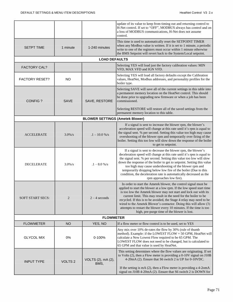
DEFAULT SETTINGS & MENU ITEM DESCRIPTIONS HeatNet Control V3 2.x
Page 71
update of its value to keep from timing out and returning control to the
H-Net control. If set to ―OFF‖, MODBUS always has control and on
a loss of MODBUS communications, H-Net does not assume
control.
SETPT TIME 1 minute 1-240 minutes
This time is used to automatically reset the SETPOINT TIMER
when any Modbus value is written. If it is set to 1 minute, a periodic
write to one of the registers must occur within 1 minute otherwise
the BMS Setpoint will revert back to the System/Local setpoint.
LOAD DEFAULTS
FACTORY CAL? Selecting YES will load just the factory calibration values: MIN
VFD, MAX VFD and IGN VFD.
FACTORY RESET? NO
Selecting YES will load all factory defaults except the Calibration
values, HeatNet, Modbus addresses, and personality profiles for the
boiler type.
CONFIG ? SAVE SAVE, RESTORE
Selecting SAVE will save all of the current settings in this table into
a permanent memory location on the HeatNet control. This should
be done prior to upgrading new firmware or when a job has been
commissioned.
Selecting RESTORE will restore all of the saved settings from the
permanent memory location to this table.
BLOWER SETTINGS (Ametek Blower)
ACCELERATE 3.0%/s .1 – 10.0 %/s
If a signal is sent to increase the blower rpm, the blower‘s
acceleration speed will change at this rate until it‘s rpm is equal to
the signal sent. % per second. Setting this value too high may cause
overshooting of the blower rpm and temporarily over firing of the
boiler. Setting this too low will slow down the response of the boiler
to get to setpoint.
DECELERATE 3.0%/s .1 – 8.0 %/s
If a signal is sent to decrease the blower rpm, the blower‘s
deceleration speed will change at this rate until it‘s rpm is equal to
the signal sent. % per second. Setting this value too low will slow
down the response of the boiler to get to setpoint. Setting this value
too high may cause undershooting of the blower rpm and
temporarily dropping below low fire of the boiler (Due to this
condition, the deceleration rate is automatically decreased as the
rpm approaches low fire).
SOFT START SECS: 2 2 – 4 seconds
In order to start the Ametek blower, the control signal must be
applied to start the blower at a low rpm. If the low speed start time
is too low the Ametek blower may not start and lock out with its
current limit. This may result in the need for the boiler to be
recycled. If this is to be avoided, the Stage 4 relay may need to be
wired to the Ametek Blower‘s contactor. Doing this will allow (3)
attempts to restart the blower every 10 minutes. If the time is too
high, pre-purge time of the blower is lost.
FLOWMETER
FLOWMETER NO YES, NO If a flow meter or flow control is to be used, set to YES
GLYCOL MIX 0% 0-100%
Any mix over 10% de-rates the flow by 30% (rule of thumb
method). Example: if the LOWEST FLOW = 50 GPM, HeatNet will
calculate a New Lowest Flow required to be 65 GPM. The
LOWEST FLOW does not need to be changed, but is calculated to
65 GPM and that value is used by HeatNet.
INPUT TYPE VOLTS 2 VOLTS (2), mA (2),
BMS,
This setting determines where the flow values are originating. If set
to Volts (2), then a Flow meter is providing a 0-10V signal on J10B
4-20mA (2). Ensure that S6 switch 2 is UP for 0-10VDC.
If the setting is mA (2), then a Flow meter is providing a 4-2omA
signal on J10B 4-20mA (2). Ensure that S6 switch 2 is DOWN for

DEFAULT SETTINGS & MENU ITEM DESCRIPTIONS HeatNet Control V3 2.x
Page 72
4-20mA.
If the INPUT TYPE is set to BMS, a Flow Limited or a Boilers
Limited method can be used. With Flow limited a GPM value can
be written to the BMS GPM Modbus register 40019 with a valid
flow. If the Boilers Limited method is to be used, the number of
boilers that the BMS would allow HeatNet to control is written into
Modbus register 40020.
See the Flow Options section for more details.
SET PARAMETERS
LOWEST FLOW By boiler type 0-500 GPM
This is the automatic value loaded and will equal the lowest flow
required for this boiler (it is adjustable). It should be equal to the
lowest flow of the largest boiler in the system.
HIGHEST FLOW 0 Currently not used.
FULL SCALE per Flow Meter 0-1600 GPM
Enter the value of the full scale reading on the calibration card that
came with the flow meter.
Flow Factor PPG Currently not used.
SYSTEM
CONFIGURE INTERLKS The 24 VAC interlocks can be enabled or disabled for reporting.
LOAD FIRMWARE NO
Enters the Load Firmware menu. Loading new firmware allows for
upgrades and bug fixes to the HeatNet control. See the SOURCE
section below or USB FEATURES section for help in loading new
firmware. Check the http://www.knseries.com/ website periodically
for firmware updates.
SOURCE USB DRIVE USB DRIVE, USB CABLE,
SAVE FILE
Selecting USB DRIVE will read the FIRMWARE directory on a
flash drive and display any .hex files located there. Follow the on
screen prompts and then select a file using the arrow keys. Once a
file has been selected, a STORAGE LOCATION needs to be
selected. There are (2) storage locations for the new file. Location 1
is used for normal updates and Location 0 is for the factory stored
backup file. When the Storage location (default is Location 1) is
selected the file will be loaded into a permanent storage memory
location. Next, the control will reboot and copy this new program
into running memory, reboot, load factory defaults, and then reboot
again.
Selecting USB CABLE requires connecting a USB cable and
running the Firmware Update program from a PC. This process
takes longer and requires a Personal Computer (laptop) to be taken
to the boiler site. Again, follow the on screen prompts to down load
the program into a storage location as done when using the above
USB DRIVE loading menu.
Selecting SAVE FILE will display the currently stored files in the
storage memory locations. Use the arrow keys to select a stored file
for copying to running memory. When SELECT is pressed the file
will be marked so it will be loaded on the next power cycle. Power
cycle the boiler to begin copying the file from stored memory to
running memory.
NOTE: to access the factory backup program, the P3 BOOT
shunt on the control needs to be connected and the CAL/NORMAL

DEFAULT SETTINGS & MENU ITEM DESCRIPTIONS HeatNet Control V3 2.x
Page 73
switch placed in the CAL position. If the control is power cycled in
this condition, the factory program will overwrite the existing
running program. If in the LOAD FIRMWARE menus, STORAGE
LOCATION 0 will be an allowed storage location.
OPTION: NO OPTION
NO OPTION DUAL FUEL BASE LOAD
When set to DUAL FUEL, input T3/ RESERVED, OPTION input
is used to control the DUAL FUEL OPTION relay via K8 contacts
on J4.2 &.6. When set to NO OPTION the input T3/RESERVED,
OPTION relay K8 on J4.2 &.6 is inactive.
When set to BASE LOAD, the Option Relay K8 on J4.2 &.6 is used
as an enable contact for a base load boiler. The J4.1 &.5 0-10vdc/4-
20mA output is used to modulate the base load relay if it is of the
modulating type.
The limitation of the OPTION menu is that Dual Fuel cannot be
used with a Base Load boiler.
BOILER TYPE
PRODUCT: KN6 KN6-KN30
The product type allows configuration of the control for a product
(and given a personality). This allows the control to be
used/interchanged with many products. The following fields will be
adjusted for the personality of the product.
CONDENSING YES This defines a boiler as condensing or non-condensing.
BTU IN 200,000
This is the BTU input rating of the boiler. This value is not used
with this released version and is displayed only for reference. Future
releases may incorporate this feature. Check the revision history
sheet on the website.
BLOWER VFD VFD, AMETEK, EBM
This is the blower type associated with the product. This should not
be changed manually. Due to earlier models of KNs using Variable
Frequency Drives, this setting needs to be adjusted for Whirlwind
(Ametek) models. The default is for a VFD.
MASS MEDIUM LOW,MEDIUM,
HIGH
This defines the mass of the boiler. This value is not used with this
version and is displayed only for reference and future applications.
Check the revision history sheet on the website.
TURNDOWN 5:1 3:1, 4:1, 5:1
This is the turndown of the boiler. For the KN-series the default is
5:1 and determines the minimum firing percentage. 5:1 = Min 20%,
4:1 = Min 25%, 3:1 = Min 33%.
NOTE: The boiler must be set up for operation at this Turndown
rate using the Calibrate settings. This TURNDOWN setting only
controls the displayed percentage.
ALTITUDE < 2000FT < 2000 FT, > 2000 FT, > 4000 FT
This is the Altitude in feet of where the boiler is installed. On
Ametek Blowers it limits the blower output for low altitudes and
allows a higher output at higher altitudes. This setting sets the upper
range limit of the MAX VFD setting.

MODBUS COMMUNICATIONS HeatNet Control V3 2.x
Page 74
MODBUS Communications
The KN-Series control can be controlled using Modbus commands to Enable/Disable the boiler/system. A connection to the
Console Modbus Port on the Communications board is required. The Master Boiler assumes the role of MEMBER, RTU, 192Kb,
8 bits, Even Parity, 1 stop bit, when connected to a BMS (Building Management System).
The Member Boilers should not be connected to a BMS system other than to view Read Only addresses. Refer to
http://www.knseries.com/ website for greater detail on communicating with Modbus, BACnet, or LonWorks protocols.
Boiler01 = The Modbus connected boiler (Master or Standalone)
Boiler02 = Member 2
Boiler03 = Member 3
…
Boiler16 = Member 16
Figure 40 MODBUS Input/Output Variables (Read/Write)
Address Name Raw Data Type Scale Description Valid Values/Range
40001 HeatDemand 1 bit unsigned ---
Heat Demand/Request. Setting the state
member of this variable will put the boiler
in heating mode.
0 = no heat demand 1 = heat demand
40002 SetpointTimer 16 bit unsigned ---
System Setpoint Timer
The system setpoint timer and system
setpoint work in tandem to externally
control (i.e. a BMS - building management
system) the operating setpoint. The
setpoint (countdown) timer should be
loaded with a timeout value (in seconds)
prior to writing the system setpoint. When
the timer reaches zero, the control assumes
that the BMS is no longer operating and the
local setpoint (saved on the control) is
reloaded. This is a failsafe feature used to
help safeguard the system in case of BMS
failure. If the setpoint timer is not written,
a default timeout value of 60 seconds is
assumed.
0 – 65535 seconds
40003 Setpoint 8 bit unsigned 1.0 System Setpoint (see SetpointTimer) 40 - 220 °F
40004 OAResetEnable 1 bit unsigned --- Enables/Disables outdoor air reset mode. 0 = disabled 1 = enabled
40005 OARSetpoint 8 bit unsigned 1.0 Outdoor air reset setpoint. Temperature at
which boiler shuts down. 40 – 100 °F
40006 OARHighWaterTemp 8 bit unsigned 1.0
Boiler water temperature setpoint when
outdoor air temperature is at the high
outdoor air temperature setpoint
(OARHiAirTemp).
60 – 190 °F
40007 OARHighAirTemp 8 bit unsigned 1.0 High outdoor air temperature setpoint. 50 – 90 °F
40008 OARLowWaterTemp 8 bit unsigned 1.0
Header/Supply temperature setpoint when
outdoor air temperature is at the low
outdoor air temperature setpoint
(OARLoAirTemp).
70 – 220 °F
40009 OARLowAirTemp 8 bit signed 1.0 Low outdoor air temperature setpoint. -35 – 40 °F
40010 SetMonth 8 bit unsigned --- Set real time clock – month (see SetClock) 0 (January) - 11
(December)
40011 SetDay 8 bit unsigned --- Set real time clock – day (see SetClock) 1 – 31

MODBUS COMMUNICATIONS HeatNet Control V3 2.x
Page 75
Figure 40 MODBUS Input/Output Variables (Read/Write)
Address Name Raw Data Type Scale Description Valid Values/Range
40012 SetYear 8 bit unsigned --- Set real time clock – year (see SetClock) 0 – 99
40013 SetHour 8 bit unsigned --- Set real time clock – hour (see SetClock) 0 – 23
40014 SetMinute 8 bit unsigned --- Set real time clock – minute (see SetClock) 0 – 59
40015 SetSecond 8 bit unsigned --- Set real time clock – second (see SetClock) 0 – 59
40016 SetWeekday 8 bit unsigned --- Set real time clock – weekday (see
SetClock) 1 (Monday) - 7
(Sunday)
40017 SetClock 1 bit unsigned ---
Set (write) the real time clock.
Do Not Write more than once per minute
To write the real time clock, the system
variables (SetMonth, SetMonth, SetDay,
SetYear, SetHour, SetMinute, SetSecond,
SetWeekday) must first be loaded with the
correct date and time. Then, a 1 must be
written to the state portion of this system
variable to write the new date and time to
the system clock.
0 = no action 1 = set/write the clock
40018 DHWSetpoint 16 bit signed 1.0 DHW Setpoint 40 - 200 °F
40019 BMSGPMRate 16 bit unsigned 1.0
GPM rate to be loaded by BMS for
calculating how many boilers can run based
on flow. 0-1500 GPM
40020 BMSLimitBoilers 16 bit unsigned 1.0
Write the # of boilers that the BMS allows
to fire. If x boilers are available, x becomes
less than or equal to LimitBoilers. 0-16
Figure 41 MODBUS Input Variables (Read Only)
Address Name Raw Data
Type Scale Description Valid Values/Range
30001 BoilersOn 8 bit unsigned --- The number of boilers currently
running. 0 – 16
30002 Modulation 8 bit unsigned 0.01 Current system modulation level. 0 – 100 %
30003 HeaderTemp 16 bit signed 0.01 Header / System temperature. 32 – 250 °F
30004 SupplyTemp 16 bit signed 0.01 Supply temperature. 32 – 250 °F
30005 ReturnTemp 16 bit signed 0.01 Return temperature. 32 – 250 °F
30006 OutsideTemp 16 bit signed 0.01 Outside air temperature. -40 – 250 °F
30007 Spare1 16 bit signed --- Raw A/D value from spare 1 input. -32768 to 32767
30008 Spare2 16 bit signed --- Raw A/D value from spare 2 input. -32768 to 32767
30009 Month 8 bit unsigned --- Real time clock month. 0 (January) - 11
(December)
30010 Day 8 bit unsigned --- Real time clock day. 1 – 31
30011 Year 8 bit unsigned --- Real time clock year. 0 – 99
30012 Hour 8 bit unsigned --- Real time clock hour. 0 – 23
30013 Minute 8 bit unsigned --- Real time clock minute. 0 – 59
30014 Second 8 bit unsigned --- Real time clock second. 0 – 59

MODBUS COMMUNICATIONS HeatNet Control V3 2.x
Page 76
Figure 41 MODBUS Input Variables (Read Only)
Address Name Raw Data
Type Scale Description Valid Values/Range
30015 Weekday 8 bit unsigned --- Real time clock weekday. 1 (Monday) – 7 (Sunday)
30016 Boiler01Status1
16 bit unsigned ---
Boiler (1 – 16) status flags. These bits indicate the state of the 24VAC
interlocks, ignition circuit, and various other conditions. See the values
column for a list of conditions.
Boiler01 = Master Boiler02 = Member01
… Boiler16 = Member15
See the ―BoilerStatus1‖ and ―BoilerStatus2‖ Tables
below.
30017 Boiler01Status2
30018 Boiler02Status1
30019 Boiler02Status2
30020 Boiler03Status1
30021 Boiler03Status2
30022 Boiler04Status1
30023 Boiler04Status2
30024 Boiler05Status1
30025 Boiler05Status2
30026 Boiler06Status1
30027 Boiler06Status2
30028 Boiler07Status1
30029 Boiler07Status2
30030 Boiler08Status1
30031 Boiler08Status2
30032 Boiler09Status1
30033 Boiler09Status2
30034 Boiler10Status1
30035 Boiler10Status2
30036 Boiler11Status1
30037 Boiler11Status2
30038 Boiler12Status1
30039 Boiler12Status2
30040 Boiler13Status1
30041 Boiler13Status2
30042 Boiler14Status1
30043 Boiler14Status2
30044 Boiler15Status1
30045 Boiler15Status2
30046 Boiler16Status1
30047 Boiler16Status2
30048 Boiler01RuntimeHigh16
16 bit unsigned ---
Boiler (1 – 16) Runtime seconds High (Upper) and Low (Lower) 16 bit
counters. To get the actual runtime for any given boiler (##), the high and low
16 bit counters must be combined (concatenated) into a single 32 bit
counter as:
Boiler##RuntimeHigh16:Boiler##RuntimeLow16
0 – 4294967295 seconds
30049 Boiler01RuntimeLow16
30050 Boiler02RuntimeHigh16
30051 Boiler02RuntimeLow16
30052 Boiler03RuntimeHigh16
30053 Boiler03RuntimeLow16
30054 Boiler04RuntimeHigh16

MODBUS COMMUNICATIONS HeatNet Control V3 2.x
Page 77
Figure 41 MODBUS Input Variables (Read Only)
Address Name Raw Data
Type Scale Description Valid Values/Range
30055 Boiler04RuntimeLow16 Example
Boiler01Runtime = (Boiler01RuntimeHigh16 * 65536) +
Boiler01RuntimeLow16
Boiler01 = Master Boiler02 = Member01
… Boiler16 = Member15
30056 Boiler05RuntimeHigh16
30057 Boiler05RuntimeLow16
30058 Boiler06RuntimeHigh16
30059 Boiler06RuntimeLow16
30060 Boiler07RuntimeHigh16
30061 Boiler07RuntimeLow16
30062 Boiler08RuntimeHigh16
30063 Boiler08RuntimeLow16
30064 Boiler09RuntimeHigh16
30065 Boiler09RuntimeLow16
30066 Boiler10RuntimeHigh16
30067 Boiler10RuntimeLow16
30068 Boiler11RuntimeHigh16
30069 Boiler11RuntimeLow16
30070 Boiler12RuntimeHigh16
30071 Boiler12RuntimeLow16
30072 Boiler13RuntimeHigh16
30073 Boiler13RuntimeLow16
30074 Boiler14RuntimeHigh16
30075 Boiler14RuntimeLow16
30076 Boiler15RuntimeHigh16
30077 Boiler15RuntimeLow16
30078 Boiler16RuntimeHigh16
30079 Boiler16RuntimeLow16
30080 Boiler01Status3
16 bit unsigned ---
Boiler (1 – 16) stage control input flags. These bits indicate the state of
the stage control inputs. See the values column for a list of conditions.
See the ―BoilerStatus3‖ Table below.
30081 Boiler02Status3
30082 Boiler03Status3
30083 Boiler04Status3
30084 Boiler05Status3
30085 Boiler06Status3
30086 Boiler07Status3
30087 Boiler08Status3
30088 Boiler09Status3
30089 Boiler10Status3
30090 Boiler11Status3
30091 Boiler12Status3
30092 Boiler13Status3
30093 Boiler14Status3
30094 Boiler15Status3

MODBUS COMMUNICATIONS HeatNet Control V3 2.x
Page 78
Figure 41 MODBUS Input Variables (Read Only)
Address Name Raw Data
Type Scale Description Valid Values/Range
30095 Boiler16Status3
----- The following registers are available starting in firmware version 2.0 -----
30096 Boiler01SupplyTemp
16 bit signed 0.01
Boiler (1 – 16) supply temperature (if available). See BoilerStatus2 to
determine if the sensor is present.
Boiler01 = Master Boiler02 = Member01
… Boiler16 = Member15
32 – 250 °F
30097 Boiler02SupplyTemp
30098 Boiler03SupplyTemp
30099 Boiler04SupplyTemp
30100 Boiler05SupplyTemp
30101 Boiler06SupplyTemp
30102 Boiler07SupplyTemp
30103 Boiler08SupplyTemp
30104 Boiler09SupplyTemp
30105 Boiler10SupplyTemp
30106 Boiler11SupplyTemp
30107 Boiler12SupplyTemp
30108 Boiler13SupplyTemp
30109 Boiler14SupplyTemp
30110 Boiler15SupplyTemp
30111 Boiler16SupplyTemp
30112 Boiler01ReturnTemp
16 bit signed 0.01
Boiler (1 – 16) return temperature (if available). See BoilerStatus2 to
determine if the sensor is present.
Boiler01 = Master Boiler02 = Member01
… Boiler16 = Member15
32 – 250 °F
30113 Boiler02ReturnTemp
30114 Boiler03ReturnTemp
30115 Boiler04ReturnTemp
30116 Boiler05ReturnTemp
30117 Boiler06ReturnTemp
30118 Boiler07ReturnTemp
30119 Boiler08ReturnTemp
30120 Boiler09ReturnTemp
30121 Boiler10ReturnTemp
30122 Boiler11ReturnTemp
30123 Boiler12ReturnTemp
30124 Boiler13ReturnTemp
30125 Boiler14ReturnTemp
30126 Boiler15ReturnTemp
30127 Boiler16ReturnTemp
30128 Boiler01CyclesHigh16
16 bit unsigned ---
Boiler (1 – 16) Cycles High (Upper) and Low (Lower) 16 bit counters. To
get the actual cycle count for any given boiler (##), the high and low 16
bit counters must be combined (concatenated) into a single 32 bit
counter as:
0 – 4294967295
30129 Boiler01CyclesLow16
30130 Boiler02CyclesHigh16
30131 Boiler02CyclesLow16
30132 Boiler03CyclesHigh16
30133 Boiler03CyclesLow16

MODBUS COMMUNICATIONS HeatNet Control V3 2.x
Page 79
Figure 41 MODBUS Input Variables (Read Only)
Address Name Raw Data
Type Scale Description Valid Values/Range
30134 Boiler04CyclesHigh16 Boiler##CyclesHigh16:Boiler##CyclesLow16
Example
Boiler01Cycles = (Boiler01CyclesHigh16 * 65536) +
Boiler01CyclesLow16
Boiler01 = Master Boiler02 = Member01
… Boiler16 = Member15
30135 Boiler04CyclesLow16
30136 Boiler05CyclesHigh16
30137 Boiler05CyclesLow16
30138 Boiler06CyclesHigh16
30139 Boiler06CyclesLow16
30140 Boiler07CyclesHigh16
30141 Boiler07CyclesLow16
30142 Boiler08CyclesHigh16
30143 Boiler08CyclesLow16
30144 Boiler09CyclesHigh16
30145 Boiler09CyclesLow16
30146 Boiler10CyclesHigh16
30147 Boiler10CyclesLow16
30148 Boiler11CyclesHigh16
30149 Boiler11CyclesLow16
30150 Boiler12CyclesHigh16
30151 Boiler12CyclesLow16
30152 Boiler13CyclesHigh16
30153 Boiler13CyclesLow16
30154 Boiler14CyclesHigh16
30155 Boiler14CyclesLow16
30156 Boiler15CyclesHigh16
30157 Boiler15CyclesLow16
30158 Boiler16CyclesHigh16
30159 Boiler16CyclesLow16
30160 Boiler01Status4
16 bit unsigned
---
Boiler (1 – 16) status4 flags. These bits indicate the state of various boiler statuses.
Boiler01 = Master or ―Connected Boiler‖ Boiler02 = Member01
… Boiler16 = Member15
See the BoilerStatus4 Flags in Appendix A.
30161 Boiler02Status4
30162 Boiler03Status4
30163 Boiler04Status4
30164 Boiler05Status4
30165 Boiler06Status4
30166 Boiler07Status4
30167 Boiler08Status4
30168 Boiler09Status4
30169 Boiler10Status4
30170 Boiler11Status4
30171 Boiler12Status4
30172 Boiler13Status4
30173 Boiler14Status4

MODBUS COMMUNICATIONS HeatNet Control V3 2.x
Page 80
Figure 41 MODBUS Input Variables (Read Only)
Address Name Raw Data
Type Scale Description Valid Values/Range
30174 Boiler15Status4
30175 Boiler16Status4
30176 …
30207
RESERVED ---
---
---
---
30208 Boiler01DHWTemp
16 bit signed --- Boiler (1 – 16) DHW temperature (if
available). See BoilerStatus4 to 32 – 250 °F
30209 Boiler02DHWTemp
30210 Boiler03DHWTemp
30211 Boiler04DHWTemp
30212 Boiler05DHWTemp
30213 Boiler06DHWTemp
30214 Boiler07DHWTemp
30215 Boiler08DHWTemp
30216 Boiler09DHWTemp
30217 Boiler10DHWTemp
30218 Boiler11DHWTemp
30219 Boiler12DHWTemp
30220 Boiler13DHWTemp
30221 Boiler14DHWTemp
30222 Boiler15DHWTemp
30223 Boiler16DHWTemp
30224 Boiler01Modulation
16 bit signed
---
The running (―display‖) modulation. This is typically the actual running modulation
except under special circumstances when the boiler is running in a self-protection
mode (Op. Limit, ½ Fire Rate, etc.) Boiler01 = Master or ―Connected Boiler‖
Boiler02 = Member01 …
Boiler16 = Member15
0 - 100
30225 Boiler02Modulation
30226 Boiler03Modulation
30227 Boiler04Modulation
30228 Boiler05Modulation
30229 Boiler06Modulation
30230 Boiler07Modulation
30231 Boiler08Modulation
30232 Boiler09Modulation
30233 Boiler10Modulation
30234 Boiler11Modulation
30235 Boiler12Modulation
30236 Boiler13Modulation
30237 Boiler14Modulation
30238 Boiler15Modulation
30239 Boiler16Modulation
30240 OperatingSetpoint
16 bit signed
---
This is the current operating or active setpoint. It may be:
1) The normal heating setpoint. 2) The DHW setpoint if running in DHW
mode.
40 - 220 °F

MODBUS COMMUNICATIONS HeatNet Control V3 2.x
Page 81
Figure 41 MODBUS Input Variables (Read Only)
Address Name Raw Data
Type Scale Description Valid Values/Range
3) A calculated setpoint if running in Outdoor Air Reset Mode
4) The 4-20ma (0-10V) setpoint.
30241 AvailableBoilers 16 bit signed
---
The maximum number of boilers available to fire.
0 - 16
30242 BTUHigh16 32 bit unsigned
30243 BTULow16
30247 SystemReturnTemp 16 bit signed ---
The system return temperature (if available). See BoilerStatus4 to determine
if the sensor is present.
32 – 250 °F
30265 SystemFlowHigh16
32 bit unsigned 0.01
Boiler SystemFlow High (Upper) and Low (Lower) 16 bit registers. To get Boiler
SystemFlow High (Upper) and Low (Lower) 16 bit registers. To get the actual
SystemFlow, the high and low 16 bit registers must be combined (concatenated)
into a single 32 bit counter as:
SystemFlowHigh16: SystemFlowLow16
Example SystemFlow = ((SystemFlowHigh16 * 65536) + SystemFlowLow16) * 0.01
This value is either the system flow meter
reading or the value written to the BMSFlowRateGPM register by the BMS.
0-1500 GPM 30266 SystemFlowLow16
30269 HeatingBoilersOn 8 bit unsigned --- The number of boilers currently running for
heating. 0 – 16
30270 DHWBoilersOn 8 bit unsigned --- The number of boilers currently running for
DHW. 0 – 16
30271 ManualBoilersOn 8 bit unsigned --- The number of boilers currently running due to a local override, T1, T2, AA/High
Fire, etc. 0 – 16
Figure 42 MODBUS — BoilerStatus1 Flags
Bit Description Valid Values/Range
0 Pilot Valve 0 = closed, 1 = open
1 Blower Running 0 = off, 1 = running
2 Ignition Alarm 0 = ok, 1 = alarm
3 Valve Alarm 0 = ok, 1 = alarm
4 High Limit 0 = ok, 1 = tripped
5 Air Prove Switch 0 = open, 1 = closed
6 RESERVED (FACTORY)
7 Software Operator 0 = off, 1 = on
8 Header Sensor not Detected 0 = detected, 1 = not detected
9 Supply Sensor not Detected 0 = detected, 1 = not detected

MODBUS COMMUNICATIONS HeatNet Control V3 2.x
Page 82
Figure 42 MODBUS — BoilerStatus1 Flags
Bit Description Valid Values/Range
10 Return Sensor not Detected 0 = detected, 1 = not detected
11 Outside Sensor not Detected 0 = detected, 1 = not detected
12 System Pump 0 = off, 1 = on
13 Combustion Air Damper
Obsolete –Available only on v1.x controls 0 = off, 1 = on
14 Master Boiler 0 = member, 1 = master
15 Boiler Detected (at this address) 0 = not detected, 1 = detected
Figure 43 MODBUS — BoilerStatus2 Flags
Bit Description Valid Values/Range
0 Disabled – boiler is offline
For instance: Minimum off Time,Flow, Local Override, Calibrate etc 0 = enabled, 1 = disabled
1 Heat Demand 0 = no demand, 1 = demand (1)
2 Alarm
An alarm or warning condition has occurred. An attempt(s) will automatically be made to recover and resume normal operation.
0 = ok, 1 = alarm
3 Failed
A condition has occurred under which the boiler can no longer run. 0 = ok, 1 = failed
4 Member Error
An ―Alarm‖ or ―Failed‖ condition has occurred on one (or more) of the member boilers.
0 = ok, 1 = error
5 Boiler Running
Main Valve is open and Modulation Delay time has expired 0 = off, 1 = running
6 Pump Running 0 = off, 1 = running
7 Spare 3 Interlock 0 = open, 1 = closed
8 LWCO Interlock (Low Water Cut Off) 0 = open, 1 = closed
9 VFD Interlock (Variable Frequency Drive) 0 = open, 1 = closed
10 Gas Prove Interlock 0 = open, 1 = closed
11 Spare 4 Interlock 0 = open, 1 = closed
12 Operator Interlock 0 = open, 1 = closed
13 Water Prove (Flow) Interlock 0 = open, 1 = closed
14 UV Sensor Air Prove Interlock 0 = open, 1 = closed
15 Main Valve 0 = closed, 1 = open
This BoilerStatus2 Heat Demand Flag is a combination of the Heat Demand input and the Modbus Heat Demand (40001).

MODBUS COMMUNICATIONS HeatNet Control V3 2.x
Page 83
Figure 44 MODBUS — BoilerStatus3 Flags
Bit Bit Bit
0 AA High Fire 0 = off, 1 = on
1 Heat Demand (Local Override) 0 = off, 1 = on (1)
2 4-20ma Remote Enable 0 = off, 1 = on
3 Outdoor Air Reset Override 0 = off, 1 = on
4 T1 0 = off, 1 = on
5 T2 0 = off, 1 = on
6 Obsolete 0 = off, 1 = on
7 Obsolete 0 = off, 1 = on
8 reserved for future use ---
9 reserved for future use ---
10 reserved for future use ---
11 reserved for future use ---
12 reserved for future use ---
13 reserved for future use ---
14 reserved for future use ---
15 reserved for future use ---
This BoilerStatus3 Heat Demand Flag is Heat Demand input. On member boilers, this indicates a ―Local Override‖.

TROUBLESHOOTING HeatNet Control V3 2.x
Page 84
BoilerStatus4 Flags
Bit Description Valid Values/Range
0 DHW Enabled (1) DHW Mode had been enabled in the menus.
0 = off, 1 = on (menu)
1 Combustion Air Damper Prove (1) Status of Combustion Air Damper Prove Input J12B
0 = not proven, 1 = proven
2 Call Service Fault 0 = off, 1 = on
3 Air Switch (Blower) Fault 0 = off, 1 = on
4 --- ---
5 --- ---
6 --- ---
7 --- ---
8 --- ---
9 DHW Sensor not detected (1) 0 = detected, 1 = not detected
10 DHW Boiler (1) This control board has been designated a DHW boiler by cutting the DHW jumper (JPS1).
0 = no, 1 = yes (DHW jumper cut)
11 Operating Limit Clamp (1) Boiler input is being limited (clamped) due to a high supply (outlet) temperature.
0 = off, 1 = clamped
12 Firing boilers limited by value in BMS Flow Rate Register (1) 0 = not limited, 1 = limited
13 Firing boilers limited by value in BMS Limit Boilers Register (1) 0 = not limited, 1 = limited
14 Stack Sensor not detected (2) 0 = detected, 1 = not detected
15 System Return Sensor not detected (2) 0 = detected, 1 = not detected
(1) Available in firmware version 1.30+. (2) Available in firmware version 2.00+.

TROUBLESHOOTING HeatNet Control V3 2.x
Page 85
Troubleshooting
This section is included as an aide to help troubleshoot
problems with the setup and operation of the boiler. See
Appendix A for additional fault messages.
Situation:
Nothing happens when the power switch is turned
on.
1. If the Ignition Control is active, but the front panel
display is inactive check:
a. Cable and cable polarity from the control board to
the display.
b. J14 on control board. The transformer supplies
24vac to power the control.
c. Check for 120vac on the primary of the
transformer and 24vac on the secondary. If one of
the 24vac interlocks has been shorted to ground or
the 24vac output is low, the transformer may be
damaged or a 24vac circuit may be miss-wired.
The H-Net control is equipped with resettable fuses on the power input circuit. Wiring power incorrectly to the unit will cause these fuses to open. Once the incorrect wiring is corrected, the fuses should reset themselves in less than 5 minutes.
Situation:
You get the error message for the Combustion Air
Damper.
1. The prove switch for the combustion air damper is not
closing. Check to make sure the dampers are being
controlled by the output relay. Also check to make sure
the prove switch is wired and working properly.
2. If (1.) has been done and you are using SPARE 1 and
you continue to get the error message, check the sensor
TYPE specified for sensor #5 in the sensors menu. If it
is set to NONE the controller will not recognize the
closed circuit. Set the Sensor #5 to ON/OFF.
3. If you are not using the combustion air damper then it
needs to be disabled in the AUX FUNCTIONS menu.
Situation:
The display is displaying random characters or the
control keeps resetting.
There may exist a grounding problem with the controller or
one of the boilers, pumps, contactors or other devices
connected to it. If all grounding is correct, there may be an
issue with radiated or induced electrical noise (interference).
This may be caused by, arcing across a contactor's contacts
when starting a pump motor, or a large electrical load. It
may also be caused by, the ignition transformer being
improperly grounded, or the spark gap set incorrectly.
1. Attempt to identify the noise source:
2. What is the boiler/controller trying to do at the time of
the failure?
3. Is the boiler on the same circuit as the noise source?
(the boiler should have isolated power.)
4. Are shielded sensor wires used? (Ensure the shields are
grounded only at the boiler control end.)
5. Are any sensors or sensor wires located near a
transmitting antenna? (Move sensor)
Situation:
There are no heating boilers on.
1. Check the settings for WWS SETPOINT, WARM
WEATHER SHUTDOWN; if the outdoor air
temperature is above the WWS SETPOINT and
WARM WEATHER SHUTDOWN is set to YES, the
circulator pump relay will be locked out and the heating
boilers will not fire.
2. If the water temperature is within the heating band
around the setpoint, boilers will not come on. The water
temperature must fall below the lower band limit to
begin firing boilers.
Situation:
Unable to change the # of Boilers in the BOILERS
menu.
1. In H-Net method, the KN-Series control auto-detects
the boilers in the system and adjusts the # of boilers
accordingly.
2. Using H-NET, if the # of Boilers is not being adjusted
properly to the actual amount of boilers in the system,
check each boiler. There can only be (1) master boiler,
but there can be up to 15 member boilers. Currently, a
total of 16 boilers in a system.

TROUBLESHOOTING HeatNet Control V3 2.x
Page 86
Situation:
The boilers menu only indicates 1 boiler, but there
are member boilers connected and the amber light
blinks on all of the boilers communication’s jacks.
1. Ensure that the latest version of firmware is installed on
all boilers. All boilers in a system must have the same
firmware revision.
2. Ensure the proper termination is set on the Master and
the last Member boiler.
Situation:
You get the error message – WATER FLOW
SWITCH or WAITING FOR FLOW.
1. If the control does not sense a closed circuit at input
connection, WTR FLW. Check to make sure the circuit
for the circulator pump is correct, that the pump is
being energized, and that the flow prove switch is
working properly.
2. If there is no flow prove switch, check to make sure that
a jumper wire has been hooked up to J11B, WTR FLW
interlock.
Situation:
H-Net boilers are detected but then lost and then
detected again etc...
1. The H-Net communications cable may be receiving
interference from the blower, ignition, or other form of
radiated electrical noise. Termination of the jumpers
may not be correct or there is more than one master.
a. Ensure that the termination jumpers are set on the
MASTER boiler and only the LAST MEMBER
boiler. All of the other member boilers should have
their termination jumpers in the non-terminated
position.
b. There may be (2) or more MASTER boilers.
Ensure that only one header sensor is present and
connected to the SYS/DHW input. There should be
no wires or sensors connected to the SYS/DHW
input if the boiler is operating as a member. This
input is auto detected and defines the boiler as a
MASTER.
c. Ensure the cable to connect the H-Net is of a
shielded or twisted pair type. Shielding of the cable
is required.
d. Minimize the electrical interference by routing the
communications cable away from electrical noise
sources, such as: Motors, ignition controls,
contactors etc…
Situation:
Only the MASTER boiler Fires, but the system has
many boilers and is using H-Net.
1. In order for the MASTER boiler to act as a MASTER,
the header sensor must be set to TYPEZ, and there must
be a header sensor present. At power-up, the header
sensor is auto detected. If the temperature of the header
sensor at power-up is greater than –25 F and less than
240 F it is considered a valid sensor. The boiler will
default to the MEMBER mode if the temperature is not
in this range and can only be run locally or by external
inputs.
a. If the LOAD FACTORY DEFAULTS has been
used to restore all the default settings, the header
sensor has been set to NONE. This needs to be set
as stated in 1, and the header sensor will need to be
replaced or the temperature brought into a valid
range. A power cycle of the boiler will detect the
sensor if it is in the range as stated in 1.).
b. The H-Net needs a communications cable daisy-
chained between boilers. Ensure that a good
connection is made on the communications board
and that the lights on the dual RJ45 jack flash
(roughly twice a second). The MASTER is the only
one that should flash with no communications
cables plugged in.
Situation:
I am in CALIBRATE and I cannot fire the boiler to
adjust it.
1. Only one, but any one of the T1-T2 inputs can be used
to start the boiler. All other inputs are disabled. This
method prevents an external control or Building
Management System from trying to control the boiler
while it is offline and being calibrated. If the boiler is
being used as a staged boiler controlled by an external
control, the staged inputs need to be disconnected
before CALIBRATION, since more than one of the T
inputs may be closed by the external control.

TROUBLESHOOTING HeatNet Control V3 2.x
Page 87
Situation:
You have forgotten the password.
2. As a last resort, you can turn the controller off, then
depress and hold the ESC key while turning it back on.
This will load the default password ―AAAAAA‖.
Situation:
Firmware update program starts to load, but then
stops, or does not load at all.
1. Check that the termination shunts J3 and J6 are not in
the termination setting. If they are, remove them
temporarily while updating. Restore them for proper
communication with a building management system.
2. Ensure that the USB driver for your PC/Laptop
computer is properly installed.
3. Disconnect BMS or Protocessor Module if connected.
Situation:
All HeatNet Boilers fire at the same time.
1. This is usually caused by the HeatNet addresses on the
Member boilers not being set. If the address on each
boiler is not set, then all boilers will have address = 2
by default. When the Master boiler calls to fire boiler
#2, all boilers with address #2 will fire. Set each
Member boiler to a unique address from 2-16.
2. Check the ADD Boiler delay time to ensure it is at a
reasonable value. A setting of 0 will start all the boilers
at the same time.
Situation:
The boiler is showing that it is running at 45% and
there is no fire in the sight glass.
1. The Boiler always shows it‘s called for firing
modulation %. This is not an indication of what the
boiler is actually firing at. If the ignition control fails to
receive a call to fire (last interlock closed on terminal 6
of the ignition control) the display will indicate the
called for %. Check if the ignition control is in standby,
if so then the HeatNet control has closed the Start
contact on J5.10 (Limits) and is waiting for the Blower
relay to close on the ignition control which is monitored
on J5.3 of the HeatNet control.
Situation:
I can hear the blower ramping up and down and
the firing rate is changing, but the display
indicates it is running at the same modulation rate.
1. The Boiler always shows it‘s called for firing
modulation %. This is not an indication of what the
boiler is actually firing at. In this case, the boiler is
trying to meet the called for modulation % which is
displayed, but is unable to do so. The boiler protects
itself by looking at it‘s supply water temperature and
the temperature is probably in the Operating Limit
Band. While in the operating limit band, the HeatNet
control limits the input of the boiler. The boiler tries to
deliver the most input it can in an attempt to meet the
called for modulation % without tripping the operating
limit.
2. If the boiler is constantly varying in blower speed and
in the operating limit band there may be not enough
flow through the boiler or the Operating
Limit/Operating Limit Band may be improperly set.
The Operating Limit/Operating Limit Band should not
overlap the heating band. This may occur when a
building management system is controlling the setpoint
and is setting the setpoint in the operating limit band.
3. Example: Setpoint set to 180F (by Building
Management) and the Operating Limit is set to 200F
with a 20F Operating Limit Band. When the boiler is
trying to deliver 180F to the load it‘s supply
temperature would be a minimum of 180F. The
beginning of the Operating Limit Band (looks at supply
temp) would be 200F-20F = 180F. Now, when the
Master is trying to maintain setpoint at 180F, the boiler
is trying to reduce input beginning at 180F at its supply
sensor and as a result, fighting the setpoint. The
Operating Limit band needs to be reduced in this case,
while taking into account the Heat Band differential.
Situation:
The Master boiler sees all of the Member boilers in
the system, but does not fire any of the Members.
1. If the Master modulates to 100% without firing a
Member boiler and the Member boilers are seen by the
Master (in menu SETUP:BOILERS), then the Member
boilers are sending back offline status to the Master.
a. The Member boilers may have an alarm or error
condition which would be indicated by a blinking
boiler # in the Boilers Firing screen.
b. Ensure the HeatNet is set up properly: Amber
lights blink on HeatNet Jacks. Only one Master
boiler.
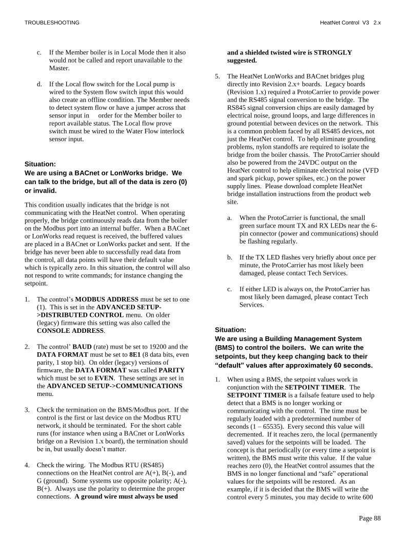
TROUBLESHOOTING HeatNet Control V3 2.x
Page 88
c. If the Member boiler is in Local Mode then it also
would not be called and report unavailable to the
Master.
d. If the Local flow switch for the Local pump is
wired to the System flow switch input this would
also create an offline condition. The Member needs
to detect system flow or have a jumper across that
sensor input in order for the Member boiler to
report available status. The Local flow prove
switch must be wired to the Water Flow interlock
sensor input.
Situation:
We are using a BACnet or LonWorks bridge. We
can talk to the bridge, but all of the data is zero (0)
or invalid.
This condition usually indicates that the bridge is not
communicating with the HeatNet control. When operating
properly, the bridge continuously reads data from the boiler
on the Modbus port into an internal buffer. When a BACnet
or LonWorks read request is received, the buffered values
are placed in a BACnet or LonWorks packet and sent. If the
bridge has never been able to successfully read data from
the control, all data points will have their default value
which is typically zero. In this situation, the control will also
not respond to write commands; for instance changing the
setpoint.
1. The control‘s MODBUS ADDRESS must be set to one
(1). This is set in the ADVANCED SETUP-
>DISTRIBUTED CONTROL menu. On older
(legacy) firmware this setting was also called the
CONSOLE ADDRESS.
2. The control‘ BAUD (rate) must be set to 19200 and the
DATA FORMAT must be set to 8E1 (8 data bits, even
parity, 1 stop bit). On older (legacy) versions of
firmware, the DATA FORMAT was called PARITY
which must be set to EVEN. These settings are set in
the ADVANCED SETUP->COMMUNICATIONS
menu.
3. Check the termination on the BMS/Modbus port. If the
control is the first or last device on the Modbus RTU
network, it should be terminated. For the short cable
runs (for instance when using a BACnet or LonWorks
bridge on a Revision 1.x board), the termination should
be in, but usually doesn‘t matter.
4. Check the wiring. The Modbus RTU (RS485)
connections on the HeatNet control are A(+), B(-), and
G (ground). Some systems use opposite polarity; A(-),
B(+). Always use the polarity to determine the proper
connections. A ground wire must always be used
and a shielded twisted wire is STRONGLY
suggested.
5. The HeatNet LonWorks and BACnet bridges plug
directly into Revision 2.x+ boards. Legacy boards
(Revision 1.x) required a ProtoCarrier to provide power
and the RS485 signal conversion to the bridge. The
RS845 signal conversion chips are easily damaged by
electrical noise, ground loops, and large differences in
ground potential between devices on the network. This
is a common problem faced by all RS485 devices, not
just the HeatNet control. To help eliminate grounding
problems, nylon standoffs are required to isolate the
bridge from the boiler chassis. The ProtoCarrier should
also be powered from the 24VDC output on the
HeatNet control to help eliminate electrical noise (VFD
and spark pickup, power spikes, etc.) on the power
supply lines. Please download complete HeatNet
bridge installation instructions from the product web
site.
a. When the ProtoCarrier is functional, the small
green surface mount TX and RX LEDs near the 6-
pin connector (power and communications) should
be flashing regularly.
b. If the TX LED flashes very briefly about once per
minute, the ProtoCarrier has most likely been
damaged, please contact Tech Services.
c. If either LED is always on, the ProtoCarrier has
most likely been damaged, please contact Tech
Services.
Situation:
We are using a Building Management System
(BMS) to control the boilers. We can write the
setpoints, but they keep changing back to their
―default‖ values after approximately 60 seconds.
1. When using a BMS, the setpoint values work in
conjunction with the SETPOINT TIMER. The
SETPOINT TIMER is a failsafe feature used to help
detect that a BMS is no longer working or
communicating with the control. The time must be
regularly loaded with a predetermined number of
seconds (1 – 65535). Every second this value will
decremented. If it reaches zero, the local (permanently
saved) values for the setpoints will be loaded. The
concept is that periodically (or every time a setpoint is
written), the BMS must write this value. If the value
reaches zero (0), the HeatNet control assumes that the
BMS in no longer functional and ―safe‖ operational
values for the setpoints will be restored. As an
example, if it is decided that the BMS will write the
control every 5 minutes, you may decide to write 600

TROUBLESHOOTING HeatNet Control V3 2.x
Page 89
seconds (10 minutes) to the setpoint timer. If after 10
minutes (5 minutes longer than the normal write
interval) the BMS has not written the timer, the saved
setpoint values will be restored.
2. As a convenience, the SETPOINT TIMER is
automatically loaded with 60 seconds (if it has fallen
below 60) each time the setpoint is written. If you
decide to take advantage of this convenience, you
would need to write the setpoint periodically at less
than 1 minute intervals.
3. Newer firmware versions allow the SETPOINT
TIMER failsafe feature to be disabled by writing a zero
(0) to the timer. The feature will automatically revert
back to the enabled state whenever the control is reset
or power cycled. The SETPOINT TIMER failsafe
feature can permanently disabled (or enabled) in
firmware versions 3.35 or greater. This setting can be
changed in the ADVANCED SETUP-
>COMMUNICATIONS menu.

OPERATION HeatNet Control V3 2.x
Page 90
KN HeatNet Control Run Screen
Hold theBACKbutton downfor 5 secondsto enter the
SETUP menus
CALIBRATE
RUN %100 OUTSIDE
RUN %100 SUPPLY
RUN %100 RETURN
RUN %100 HEADER
RUN %100 SYSTEM SET
RUN %100 *STATUS
START 0STOP 0
RUN %100 BLRS FIRING
1_2______P_________2
RUN %100 MIN VFD
25%
CALIBRATE
RUN %100 IGN VFD
30%CALIBRATE
RUN %100 MAX VFD
90%CALIBRATE
RUN %100 DELTA TEMP RUN %100 DELTA TEMPCALIBRATE
MASTER:SYSTEM SETMEMBER: LOCAL SET SYSTEM SET
RUN %100
157°F
RUN %100
25°F 25°F
90°F
50°F
162°F
142°F
158°F
160°F
DHW SETPT
DHW TEMP RUN %100
157°F
RUN %100
160°F
DHW SETPT
DHW TEMP
RUN %100CALIBRATE
CALIBRATE
CALIBRATE
RUN %100
NA
SYS RETRNCALIBRATE
RUN %100CALIBRATE
RUN %100
5853
TACHCALIBRATE
RUN %100 LOCAL SET
158°F
The SETPOINT can be adjusted by pressing and holding the SELECT button until the SETPOINT flashes. Then use the UP and DOWN buttons to change the value. Pressing the SELECT button saves the value.
Press the UP or DOWN Arrow Keys to navigate the display screen.
If the Header Sensor is present the menu will display SYSTEM SET, otherwise it will display LOCAL SET.
RUN %100
RUN %100
NA
SYS RETRN
RUN %100
5853
TACH
The BLRS FIRING screen is used by the Master boiler to indicate which boilers are firing. If the boiler # is blinking a problem exists on that boiler. If a symbol is displayed, that positions boiler was detected. If a ‘D’ is displayed, the Master is controlling that boiler as a DHW boiler.To the far right the current active system pump is displayed vertically as P1 or P2 (Pump 1 or Pump 2)

OPERATION HeatNet Control V3 2.x
Page 91
KN HeatNet Control Run Screen - Continued
DHW screens are
available depending
on the DHW mode of
operation.
RUN %100
NA
SYS FLOW RUN %100
NA
SYS FLOW
RUN %100
RUN %100 DHW:
CALIBRATE
DHW STATUS
START 0STOP 0
RUN %100
RUN %100 DHW:
DHW STATUS
START 0STOP 0

OPERATION HeatNet Control V3 2.x
Page 92
KN HeatNet V3 Menu Tree — ADVANCED THERMAL HYDRONICS
HOME SCREEN
MAIN MENU SCREEN
ADVANCED MENUS
RUN %100 SYSTEM SET
140°F
Press and HOLD BACKbutton down for 5
seconds to enter themenu screen
LOCAL SETOPERATEOPLS ETPT S OURCE
I M BAND
OA RESETWARM WEATHER SD:
OFF
WWS SETPOINTSET OA S E T POINTS
A L W A Y S
T E M PD E L T A T E M P
P O S TO F F
D E L T A
E
E N A B1 0 °
P R G EE N A B L E D
O F F
T I M 5 m
O F I L E R S# B O 1L E A D B OI L E R # 0H E A T B A N D 4 0 ° F
OPTSE TB ACKN IGHT
OPT I O
PUMP I ONS
NS
AUX F UNCT
S YS TEM
I ONS
CL OCK
A U T O
P O S T P R G E T I M E 5 m
S U M M E R P U M P J O G : O F F
L IM
OFF68°F
T Y P E : L I N K E D C O M M O N
P R O O F T I M E
I N U S E ?I N P U T : J 1 2 B P I N 7
2 : 0 0
Y E S
DOMESTIC HOT WATER
NM A S T E R P U M P / V A L V ER E M A I N S O N : O F F
L O C A L P U M P V F D : O F F
LOG/RUNTIME
LOG / RUN T I ME
H N T 1 2
B O I L E R S S E T P O I NT S OUT DOOR A I R RE S E T
2 : 4 6 : 0 3 P 0 2 / 2 0 1 3
S E TUP ADVANCE D S E T UP V I E W L OG
2O 7 7 ° S E 1 6 0 ° FA NA MOD% 4 0 M - - - - - - P S MPB - RM
O
1H TF
AT WAT E R T EMP 1 4 0 °
H I GH OA T EMP 7 0 °
WAT E R T EMP 1 8 0 ° AT
L OW OA T EMP 1 0 ° BACK
NEX T
F
F
F
F
FFF
°°°1 6 0
220 0
0
T I ME :9 2 M5 A
DAY
Y E AR 20 1 2
2 7
DAY OF WE E K T UEMONT H S E P
O V R E N A B I N W W S : O F F
P U M P R O T A T I O NR O T A T I O N : N O N E
R O T A T E T I M EM O R E M E N U S
S Y S T E M P U M P S : 2: 9 6 H R
2 5 0 H R
Z E R O R U N T I M E P U M P 1P U M P 1 T I M E 1 1 2 H RP U M P 2 T I M EA L W A Y S E N A B L E D O F F
K N 3 0 V 2 . 0 0
N I G H T S E T B A C K
FI
T E M P S C A L EK E Y C L C K O NS K I P P A S S WO R D O NB R I G H T N E S S 5 0 %
DATA L OG ENTRYRUN HOURS
S I Z E
C O M B U S T A I R D A M P E RA LA R M S I L E N C E
H E A T E X C H A N G E R
PUMP/VALVE OPTION
S Y S T E M P U M PL O C A L P U M P
BOIL ER CYCL ES
FLOW PROVE:
F A I L S A F E M O D E S
DHW BOILER?DHW SETPOINT
3°F
USE SENSOR?
LOWER DHW DIFF
NO160°F
5°F
DHW PRIORITY?POST PURGE
NO120S
NO
UPPPER DHW DIFF
SHARING
PURGE TO THE:
LOCAL PUMP OFF:LOCAL DELAY
YES10S
TANKHYB SENSOR: SUPPLY

OPERATION HeatNet Control V3 2.x
Page 93
KN HeatNet V3 Advanced Menu Tree – ATH
L A S TL A S TM A XM A XMODMOD
D E L A YD E L A Y
--MODULATEMODULATE
F I R EF I R E
CAL ICAL I BRABRA TE?TE? NONO
PLACEPLACE AA PRECPREC II S IS I ONON1K1K OROR 1OK1OK RESRES II STORSTORONON CHANNELCHANNEL ## ____
TRIMTRIM OHMSOHMS == __ __ __
TRIMTRIM VALUEVALUE SET!SET!
OOAA DDAACCLL
GGOO
HH NN PP SSSS WW RRDD ::
EE WW ::-- -- -- -- -- --
-- -- -- -- ----
F IRINGFIRING MODEMODE
SENSORSSENSORSBASE LOADINGBASE LOADING
BLOWER SETT I NGSBLOWER SETT I NGSDEFAULTSDEFAULTSLOADLOAD
COMMUNICATIONSCOMMUNICATIONS
C T R LC T R LD I S T R I B U T E DD I S T R I B U T E D
A D A P T I V E M O DA D A P T I V E M O DF I R I N GF I R I N G M O D EM O D E
CACA L?L?FACTFACT ORYORYRERE SET?SET? NONOFACTFACT ORYORY
NONO
H-H- NETNETCC ONTROLONTROLMASMAS TERTER YESYES
11255255H - N E T A D D R E S SH - N E T A D D R E S S
MODBUS ADDRESSMODBUS ADDRESS
H-H- NETNET
A D D B O I L E RA D D B O I L E RD E L A YD E L A YS H E D B O I L E RS H E D B O I L E R
D E L A YD E L A Y
TIMETIME0 SECONDS0 SECONDS
ADD DELAY TIMEADD DELAY TIME
4 MINUTES4 MINUTES
SHED DELAY TIMESHED DELAY TIME
2 MINUTES2 MINUTES0 SECONDS0 SECONDS
MODULATE DELAY TIMEMODULATE DELAY TIME
0 MINUTES0 MINUTES10 SECONDS10 SECONDS
STOP MOD MAXSTOP MOD MAX
% 70% 70
MOD MODE: ADAPTIVEMOD MODE: ADAPTIVEDROP DOWN: ON PILOTDROP DOWN: ON PILOTDELAY RELEASE :DELAY RELEASE : 0s0s
4-20mA INPUT4-20mA INPUT
BOILER STARTBOILER START
4mA SETPOINT4mA SETPOINT20mA SETPOINT20mA SETPOINT
68°F68°F200°F200°F
4.11mA4.11mAPRIORITYPRIORITY NORMALNORMAL
M O D U L A R B O I L E R S E TM O D U L A R B O I L E R S E T
PASSWORDPASSWORD
10 HRs10 HRsTRUETRUEMODEMODE
0m0mMIN RUNTIME:MIN RUNTIME:MIN OFFTIMEMIN OFFTIME
9595
10mins10mins
BASE LOAD BOILERS: 0BASE LOAD BOILERS: 0START > MODSTART > MODSTOP F IRSTSTOP F IRSTDELAY T IMEDELAY T IME
START PRIORITY 1START PRIORITY 1SET: F IRSTSET: F IRSTSTOP PRIORITY 1STOP PRIORITY 1SET: LASTSET: LAST
BTU IN 2000,000BTU IN 2000,000CONDENSING YESCONDENSING YES
BOI LER TYPEBOI LER TYPE
LOAD F I RMWARELOAD F I RMWAREOPTION: NO OPTIONOPTION: NO OPTION
CC OMMOMMUU NN II CACA TT II ONSONSBAUD 19200BAUD 19200DATA FORMAT 8E1DATA FORMAT 8E1
SETPOINT T IMER ONSETPOINT T IMER ON
NN
EE
SENSORSENSOR ASS IGNMENTSASS IGNMENTSSENSOR #SENSOR #TYPETYPE
OUTS IDEOUTS IDE
NONENONE
ANALOG IN CHANNEL :1ANALOG IN CHANNEL :1CHANNEL MODE:CHANNEL MODE:
0- 10V0- 10V
SYSTEMSYSTEM
DEFAULTSDEFAULTSLOADLOADCOMMUNICATIONSCOMMUNICATIONS
BLOWER SETT I NGSBLOWER SETT I NGS
SOFT START SECS :SOFT START SECS :
3 .0%/S3.0%/S
DECELERATEDECELERATEACCELERATEACCELERATE
2.0%/S2.0%/S22
CONFIGURE I NTERLKSCONFIGURE I NTERLKS
LOAD F IRMWARELOAD F IRMWARESOURCESOURCE
INTRLK ASSIGNMENTSINTRLK ASSIGNMENTSSYSTEM FLOW: ONSYSTEM FLOW: ON
USB DRIVEUSB DRIVE
BLOWER:BLOWER:
< 2000FT< 2000FTTURNDOWNTURNDOWN
ALTITUDE:ALTITUDE:
YESYESPREDICT START:PREDICT START:
MORE MENUSMORE MENUS
FIRING PRIORITY : 2F IRING PRIORITY : 2
PRODUCT:PRODUCT: KN30KN30
MORE MENUSMORE MENUS
AMETEKAMETEKMASS MEDIUMMASS MEDIUM
5 :15 :1
D H W H E A T I N GD H W H E A T I N GS P A C E H E A T I N GS P A C E H E A T I N G

WORKSHEET HeatNet Control V3 REV 2.x
Page 94
Worksheet
SETUP MENU
BOILERS
# of BOILERS
LEAD STAGE
HEAT BAND °
SETPOINTS
SYSTEM/LOCAL SETPOINT °
OPERATE LIMIT °
OP LIM BAND °
SETPOINT SOURCE
OUTDOOR AIR RESET °
OA RESET
WARM WEATHER SD
WWS SETPOINT °
SET OA SETPOINTS
WATER TEMP °
@
HIGH OA TEMP °
WATER TEMP °
@
LOW OA TEMP °
PUMP OPTIONS
SYSTEM PUMP
POST PURGE TIME
PUMP ROTATION
ROTATION:
SYSTEM PUMPS:
ROTATE TIME:
MORE MENUS
ZERO RUNTIME PUMP
PUMP1 TIME
PUMP2 TIME
ALWAYS ENABLED
SUMMER PUMP JOG
OVR ENAB IN WWS
LOCAL PUMP
DELTA TEMP ENAB
DELTA TEMP °
POST PRGE TIME s
ALWAYS ENABLED
PUMP/VALVE OPTION

WORKSHEET HeatNet Control V3 REV 2.x
Page 95
REMAINS ON:
LOCAL PUMP VFD
FLOW PROVE
NIGHT SETBACK
SETBACK ENTRY 1 2 3 4
ENTRY IS
SETBACK ° ° ° °
SETBACK TIME
START DAY
TIME
END DAY
TIME
OPTIONS
TEMP SCALE °
KEY CLICK
SKIP PASSWORD
BRIGHTNESS %
LOG/ RUNTIME
RUN HOURS
DATA LOG ENTRY
SIZE
BOILER CYCLES
AUX FUNCTIONS
COMBUST AIR DAMPER
TYPE:
IN USE?
INPUT:
PROOF TIME
ALARM SILENCE SWITCH
IN USE
INPUT:
FAILSAFE MODES
H-NET COMM LOST
LOW TEMP:
TEMP <
HEAT EXCHANGER
EXCHGR DELTA T
LIMIT-> HALF RATE
DOMESTIC HOT WATER
DHW BOILER?
DHW SETPOINT
LOWER DHW DIFF
UPPER DHW DIFF
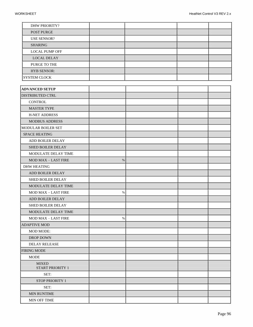
WORKSHEET HeatNet Control V3 REV 2.x
Page 96
DHW PRIORITY?
POST PURGE
USE SENSOR?
SHARING
LOCAL PUMP OFF
LOCAL DELAY
PURGE TO THE
HYB SENSOR:
SYSTEM CLOCK
ADVANCED SETUP
DISTRIBUTED CTRL
CONTROL
MASTER TYPE
H-NET ADDRESS
MODBUS ADDRESS
MODULAR BOILER SET
SPACE HEATING
ADD BOILER DELAY
SHED BOILER DELAY
MODULATE DELAY TIME
MOD MAX – LAST FIRE %
DHW HEATING
ADD BOILER DELAY
SHED BOILER DELAY
MODULATE DELAY TIME
MOD MAX – LAST FIRE %
ADD BOILER DELAY
SHED BOILER DELAY
MODULATE DELAY TIME
MOD MAX – LAST FIRE %
ADAPTIVE MOD
MOD MODE:
DROP DOWN
DELAY RELEASE
FIRING MODE
MODE
MIXED
START PRIORITY 1
SET:
STOP PRIORITY 1
SET:
MIN RUNTIME
MIN OFF TIME

WORKSHEET HeatNet Control V3 REV 2.x
Page 97
FIRING PRIORITY
PREDICT START
BASE LOADING
BASE LOAD BOILERS:
START > MOD
STOP
DELAY TIME
SENSORS
SENSOR # OUTDSIDE SUPPLY R E T U R N H E A D E R DHW 6 7 8
TYPE
4-20mA INPUT
ANALOG IN CHANNEL:
CHANNEL MODE:
4mA SETPOINT
20mA SETPOINT
BOILER START
PRIORITY
PASSWORD
COMMUNICATIONS
BAUD
DATA FORMAT
SETPOINT TIMER
SETPOINT TIME
FLOWMETER
FLOWMETER
GLYCOL MIX
INPUT TYPE
LOWEST FLOW
HIGHEST FLOW
FULL SCALE
FLOW FACTOR
BLOWER SETTINGS (AMETEK
BLOWER)
ACCELERATE
DECELERATE
SOFT START SECS:
OFF BOILER-BLOWR%
SYSTEM
CONFIGURE INTERLKS
INTRLK ASSIGNMENTS
SYSTEM FLOW… ON
LOAD FIRMWARE Version:
OPTION:

WORKSHEET HeatNet Control V3 REV 2.x
Page 98
BOILER TYPE
PRODUCT
CONDENSING
BTU IN
BLOWER
MASS
TURNDOWN
ALTITUDE
CALIBRATION SETTINGS
MIN VFD
IGN VFD
MAX VFD

HeatNet V3 2.x
Page 99
Type II Thermistor Resistance/Temperature Table
Temp C Temp F Resistance Temp C Temp F Resistance
-40 -40 336,450 60 140 2,488
-35 -31 242,660 65 149 2,083
-30 -22 176,960 70 158 1,752
-25 -13 130,410 75 167 1,479
-20 -4 97,072 80 176 1,255
-15 5 72,951 85 185 1,070
-10 14 55,326 90 194 915.4
-5 23 43,326 95 203 786.6
0 32 32,650 100 212 678.6
5 41 25,391 105 221 587.6
10 50 19,899 110 230 510.6
15 59 15,711 115 239 445.2
20 68 12,492 120 248 389.6
25 77 10,000 125 257 341.9
30 86 8,057 130 266 301.0
35 95 6,531 135 275 265.8
40 104 5,326 140 284 235.4
45 113 4,368 145 293 209.0
50 122 3,602 150 302 186.1
55 131 2,986

HeatNet V3 2.x
Page 100
* Status Information
Whenever an * is displayed on the RUN screen it indicates that there is more information available about the current running
conditions. This information can be viewed by going to the *STATUS screen as shown on the previous page. For more
information on the parameters discussed here please see the Default Settings & Menu Item Descriptions — SETUP, starting on
page 61.
Status information screens
This screen indicates that the boiler‟s SUPPLY
Temperature has gone above the OPERATOR
LIMIT. This will mainly be seen on member
boilers to show why they are not available to fire.
This screen indicates that the boiler‘s SUPPLY
temperature has risen inside the OPERATOR LIMIT
BAND.
This screen indicates the boiler‘s input is being
limited by the MOD-MAX value to optimize system
efficiency. This will only be seen on a MASTER
boiler.

HeatNet V3 2.x
Page 101
Status information screens
This screen indicates the control is attempting to re-
initiate the ignition control because the ignition
control did not begin PRE-PURGE. For more
information see CALL SERVICE LOG entry.
This screen indicates that the boiler‘s has received a
heat demand, but it‘s MINIMUM OFF time has not
expired.
This Screen indicates that the boiler‘s input is
temporarily being limited to optimize the boiler‘s
efficiency.
This screen indicates that the boiler is running in
LOCAL MODE because it has lost H-NET
communications with the MASTER, and the failsafe
mode has been activated.

APPENDIX A HeatNet V3 2.x
Page 102
Status Screen Fault Display
There are numerous interlock switches and software
limits that are detected. Each of these, when tripped will
produce a display message, an audible beeping, and an
alarm relay closure. The fault is displayed first, then after
a second, the time the fault occurred is displayed. This
cycle will keep occurring until the fault is cleared.
These faults and interlocks are:
HIGH LIMIT:
When the high limit aquastat trips the following message
is displayed:
The high limit interlock breaks power to the ignition
control (shutting it off) and effectively removes any
chance of the gas valve receiving power. The HeatNet
series control will remain powered to display the fault,
latch the alarm relay/audible beeper, and to access the log.
The interlock is located on J5, HIGH LIMIT. Ensure
power is present on the input to the High Limit Control.
SPARE 4:
This is a reserved interlock input that is user defined. The
interlock is located on J5B, SPARE 4.
DELTA TEMPERATURE WARNING:
If the temperature difference across the boiler measured
from RETURN water to SUPPLY water exceeds the
EXCHR DELTA T RANGE, setting this message will be
displayed.
LOW WATER CUTOFF:
If there is a low water condition reported by the low water
cutoff switch this fault is displayed. Check that there is water
flow and water in the boiler. There is a reset switch located on
the LWCO box. The interlock connection is located on J5B,
LWCO.
VAR FREQ DRIVE:
The variable frequency drive, which controls a non Ametek
blower, if supported, reports this fault. It may be caused in the
event of over current or an internal VFD fault that would
cause it to shut down. If this is the case, check the fault
indicators on the VFD. The interlock is located on J5B, VFD.
GAS PRESSURE:
The gas pressure switches (high pressure and low pressure) are
connected in series, so if either trip, a fault will be reported
here. A reset switch is located on the gas pressure switches.
The interlock is located on J15B, GAS PR.
SYSTEM WATER FLOW:
Once the HeatNet series boiler receives a call for heat, it
closes the system circulator pump relay. It then waits 10
seconds or more (adjustable) to prove flow. If there is no flow,
the flow switch alarm will be set. Every 10 seconds the
circulator pump relay will cycle ON for 10 seconds and then
OFF for 10 seconds to try and establish flow. The interlock
connection is located on J5B, SYSTEM WTR FLOW.

APPENDIX A HeatNet V3 2.x
Page 103
WTR FLW LOCAL:
Once the HeatNet series boiler receives a call for heat, it
closes the LOCAL PUMP/VALVE relay. It then waits 10
seconds or more (adjustable) to prove flow. If there is no
flow, the flow switch alarm will be set. Every 10 seconds
the circulator pump relay will cycle ON for 10 seconds
and then OFF for 10 seconds to try and establish flow.
The interlock connection is located on J5B, WTR FLW.
IGNITION CTRL ALARM:
The ignition control alarm is displayed if the ignition
control detects a fault. This could be a flame failure, air
proving switch, or other fault associated with the ignition
control. When this fault occurs, you will need to refer to
the ignition control for the reason.
COMBUST AIR DAMPER:
If the combustion air damper has been selected for use
(AUX FUNCTIONS), and the proof switch does not
make, this fault will be displayed.
When the master boiler receives a call for heat and needs
to start a boiler, the DAMPER relay closes on J13. If the
combustion air damper does not prove within the proof
time specified in the combustion air damper menu, the
boiler will not start and then display the fault. A
combustion damper fault on a boiler can only be cleared
by power cycling.
OPEN ******* SENSOR :
If the open sensor fault is displayed, the sensor in the position
reported was originally detected, but has since opened. The
boiler will shut down on any OPEN sensor except the
OUSTSIDE AIR sensor.
SHORTED ******* SENSOR:
If the shorted sensor fault is displayed, the sensor in the
position reported was originally detected, but has since
shorted. The boiler will shut down on any SHORTED sensor
except the OUSTSIDE AIR sensor.
AIR SWITCH:
If the IGNITION control closes its blower relay, the control
does not see the PILOT relay close within (2) minutes, and the
AIR PRESSURE switch is made, this message will be
displayed. This alarm protects the boiler from freeze ups being
caused by a blower bringing in cold outside air with no fire.
CALL SERVICE:
If the H-Net control closes the last interlock string entering the
ignition control and the ignition control never closes its
Blower Relay, the H-Net control will wait 2 minutes. The H-
Net control will then retry for the duration of the local pump
post purge time and then retry the ignition sequence. During
this time ―retry strt‖ will be displayed in the status screen.
After (5) attempts the H-Net control will lock out and display
call service.

APPENDIX A HeatNet V3 2.x
Page 104
DELTA TEMPERATURE WARNING:
If the temperature difference across the boiler and
measured from RETURN water to SUPPLY water
exceeds ―EXCHGR DELTA‖ this message will be
displayed. This can be set to an alarm condition in the
AUX FUNCTIONS menu. High delta temperatures can
result in damage to the boiler.
BLOWER, RPM HIGH: (Ametek Blower)
If the signal from the HeatNet control board to the
Ametek blower exceeds the factory limits, or the blower
―runs away‖ (excessive speed), this message will be
displayed. With this event, the HeatNet control will
lockout the boiler and the boiler will require a manual
reset to restart. Operation of the blower above the boiler‘s
maximum blower rpm setting could over fire the boiler.
BLOWER, RPM HIGHFAULT
HIGH FIRE
TACH
0

APPENDIX B HeatNet V3 2.x
Page 105
Line 4 Log Entries:
The following table lists the messages on line # 4 of the log‘s display.
Line # 4 Message Description
SETBACK IS ACTIVE
SETBACK EXPIRED
If any of the (4) temperature setbacks are active these log entries will be
displayed in the log.
NO LOCAL FLOW
NO SYSTEM FLOW
If the test for flow fails these log entries will be displayed. The flow proving
switches are wired to J11A and J11B.
COMBUSTION AIR FAIL
If the combustion air damper is used and does not prove across J10B
DAMPER or J12B DAMPER, this message is displayed.
SYSTEM RESET -- ----
O: stack overflow,
U: Stack Underflow ( both are software faults)
R: Reset Instruction ( Firmware or Default load),
W: Watchdog ( Firmware code ran erroneous code and
rebooted),
P: Power-ON (Power switch toggled),
B: Brown-out ( Microcontroller saw a voltage less than 4.5
VDC)
When the control is reset, this log entry captures the reason the reset occurred.
OUTDOOR RESET
This log entry indicates that Warm Weather Shutdown is in effect.

APPENDIX B HeatNet V3 2.x
Page 106
Line # 4 Message Description
HIGH DELTA TEMP
This log entry occurs when the temperature across the heat exchanger has
been greater than the EXCHR DELTA T RANGE degrees F.
SHUTDOWN UV TEST
After 24 hours of continuous runtime the ignition control module needs to
check it‘s UV detection circuit. An orderly shutdown and then a restart will
occur. This log entry indicates that this has taken place. This is not a fault.
HIGH LIMIT EXCEEDED
If the mechanical aguastat trips due to it‘s high temperature setting having
been exceeded, this log entry will occur.
IGNITION CTRL ALARM
The ignition control module has faulted while performing an ignition
sequence, or while monitoring flame during normal operation.
IRI Alarm
If the gas valve proving circuit ( if equipped) detects a gas pressure problem.
DOMESTIC HOT WATER
Indicates a call for DHW heating by either the DHW sensor or an external
thermostat.
LOW WATER CUTOFF
VAR FREQ DRIVE
GAS PRESSURE
SPARE 4
OP LIMIT MECH
These log entry faults are result of the interlocks connected to the 24VAC
interlock inputs: J11A and J11B.
Low Water Cutoff = Low water condition in boiler
Var Freq Drive = The blowers Variable Frequency Drive has a problem
Spare 4 = User installed interlock,
Op Lim Mech = An external operator (aquastat).
START FAILED, RETRY
If the H-Net control closes the last interlock string entering the ignition
control and the ignition control never closes its Blower Relay, the H-Net
control will wait 2 minutes. The H-Net control will then retry for the duration
of the local pump post purge time and then retry the ignition sequence. During
this time ―retry strt‖ will be displayed in the status screen. After (5) attempts
the H-Net control will lock out and display call service. The Log will report
the retries.
OP LIMIT REMOTE
The is the firmware Operating Limit as defined in
SETUP:SETPOINTS:OPERATE LIM. When the Supply temperature exceeds
this value, this event is logged.
OPEN OUTSIDE SENSOR,
SUPPLY SENSOR,
RETURN SENSOR,
HEADER SENSOR,
DHW SENSOR
If one of the 10k thermistor sensors was detected to be open or not connected,
this fault will be logged.
SHORTED OUTSIDE SENSOR,
SUPPLY SENSOR,
RETURN SENSOR,
If one of the 10k thermistor sensors was detected to be shorted this fault will
be logged.

APPENDIX B HeatNet V3 2.x
Page 107
Line # 4 Message Description
HEADER SENSOR,
DHW SENSOR
AIR SWITCH(BLOWER)
If a call is made to the ignition control to start and the HeatNet control detects
a blower start, but no Pilot within two minutes, the boiler locks out. This log
entry indicates that the blower was ON with no flame in the boiler. Freeze up
protection.
LOST BOILER #
FOUND BOILER #
These log entries indicate that HeatNet has either discovered a boiler or lost a
boiler using it‘s auto detection algorithm.
FAIL SAFE H-NET LOST
FAIL SAFE LOW TEMP
If the Fail Safe modes are active, these log entries indicate that they became
active for some reason and the boiler had entered Fail Safe mode.
BASE LOAD BOILER
The Base load Boiler Relay K8 is Active if ON
Inactive if OFF
CALL SERVICE
If the H-Net control closes the last interlock string connected to the ignition
control and the ignition control never closes its Blower Relay, the H-Net
control will wait 2 minutes. The H-Net control will then retry for the duration
of the local pump post purge time and then retry the ignition sequence. During
this time ―retry strt‖ will be displayed in the status screen. After (5) attempts
the H-Net control will lock out and display call service.
BLOWER, RPM HIGH The tachometer feedback from the blower indicated that it was above the
maximum speed allowed for the boiler. Only used with Ametek blowers.

IN UNITED STATES: 260 NORTH ELM ST. • WESTFIELD, MA 01085 • (413) 564-5515 • FAX (413) 568-9613IN CANADA: 7555 TRANMERE DRIVE • MISSISSAUGA, ONT. L5S 1L4 • (905) 670-5888 • FAX (905) 670-5782
www.knseries.com