control systems - dis.uniroma1.itlanari/controlsystems/cs - lectures/2014_lec... · electric guitar...
TRANSCRIPT

Control Systems
System as a filterL. Lanari
Monday, November 3, 2014
Lanari: CS - Filter 2
Outline
• Mass-Spring-Damper
• 7-mass system
• first order system
• second order system
• microphone
• quarter-car system
Monday, November 3, 2014

Lanari: CS - Filter 3
Mass - Spring - Damper
k
µ
p
uF (s) =
1
ms2 + µs+ km
0 < µ < 2√km p1,2 =
− µm ± j
�4�
km
�−� µm
�2
2
µ = 2√km
transfer function
• over-damped
• critically-damped
• under-damped
µ > 2√km
p1,2 = − µ
2m
p1,2 =− µ
m ±�� µ
m
�2 − 4�
km
�
2
complex conjugate poles
real coincident poles
real distinct poles
asymptotically stable system for µ > 0
Monday, November 3, 2014
Lanari: CS - Filter 4
Mass - Spring - Damper
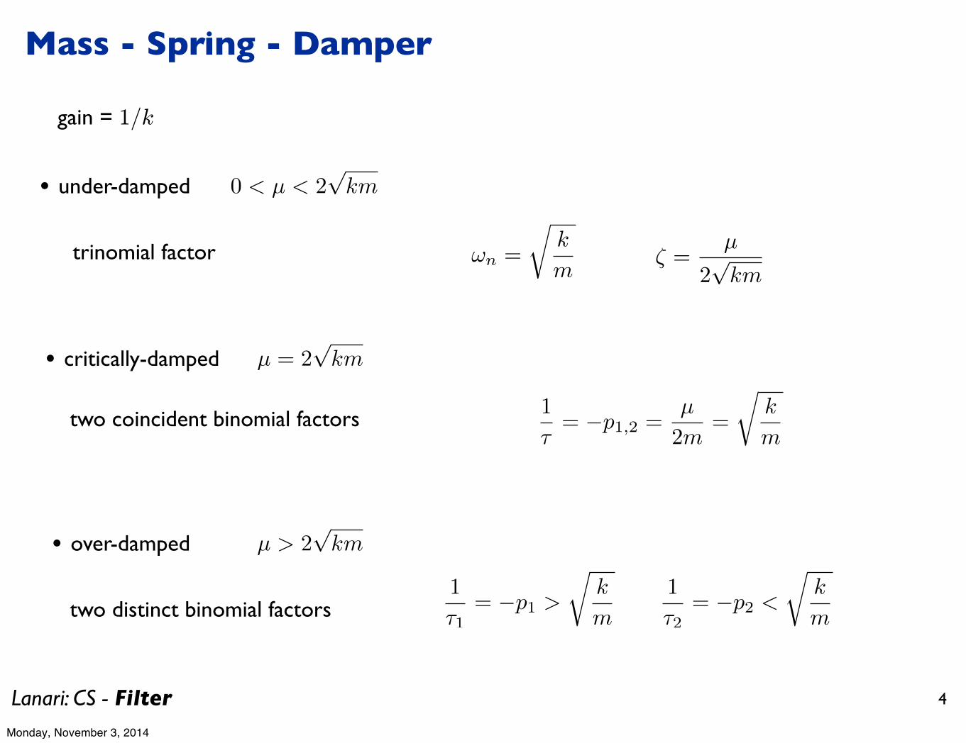
0 < µ < 2√km
µ = 2√km
• over-damped
• critically-damped
• under-damped
µ > 2√km
trinomial factor
two coincident binomial factors
two distinct binomial factors
ωn =
�k
mζ =
µ
2√km
1
τ= −p1,2 =
µ
2m=
�k
m
1
τ1= −p1 >
�k
m
1
τ2= −p2 <
�k
m
gain = 1/k
Monday, November 3, 2014

Lanari: CS - Filter 5
10!1
100
101
102
!75
!70
!65
!60
!55
!50
!45
!40
!35
!30
!25
frequency (rad/s)
Magnitude (dB)
MSD ! Magnitude with µ variable
Real coincident
Real distinct
Complex
Single binomials
Mass - Spring - Damper
m = 1 kgk = 100 N/m
magnitude in terms of the damping factor µ
the two single binomials are also shown (over-damped case) in order to put in evidence the dominant pole (corresponding to the ral pole closest to the origin)
Monday, November 3, 2014

Lanari: CS - Filter 6
input force on mass 1
7 - MSDsystem
(with damping)
100
101
102
103
!200
!150
!100
!50
Magnit
ude
100
101
102
103
!800
!600
!400
!200
0
Phase
7-mass
output position on mass 3
resonance peaks
anti-resonancepeak
natural frequenciesvery close to each other
119.6311 107.5098 78.7957 73.3411 42.2283 19.0596 11.0478
natural frequencies
Monday, November 3, 2014
Lanari: CS - Filter 7
10!2
100
102
!20
!15
!10
!5
0
5
frequency (rad/s)
Magnitude (dB)
F1
F2
F3
F4
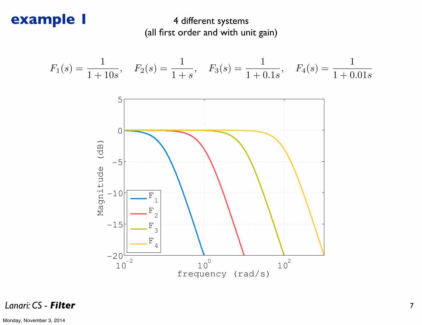
F1(s) =1
1 + 10s, F2(s) =
1
1 + s, F3(s) =
1
1 + 0.1s, F4(s) =
1
1 + 0.01s
4 different systems(all first order and with unit gain)
example 1
Monday, November 3, 2014

Lanari: CS - Filter 8
0 2 4 6 83
2
1
0
1
2
3T
Input
100
101
102
!0.5
0
0.5
frequency (rad/s)
Frequency spectrum of the input
u(t) = −0.6 sin(f1t)−0.4 sin(f2t)+0.5 sin(f3t)+0.5 sin(f4t)−0.3 sin(f5t)−0.2 sin(f6t)+0.2 sin(f7t)−0.2 sin(f8t)
f1 = 2π0.75, f2 = 2π1.25, f3 = 2π1.5, f4 = 2π3, f5 = 2π5, f6 = 2π6, f7 = 2π8, f8 = 2π11
!2
0
2
!2
0
2
!2
0
2
!2
0
2
!2
0
2
!2
0
2
!2
0
2
0 0.5 1 1.5 2 2.5 3 3.5 4!2
0
2
adding one contribution at a time
sameinformationin the frequencydomain time
time
input signal
Monday, November 3, 2014

Lanari: CS - Filter 9
10!2
10!1
100
101
102
!0.5
0
0.5
10!2
10!1
100
101
102
!0.1
0
0.1
10!2
10!1
100
101
102
0
0.5
1
Magnitude
System 2
magnitudenot in dB
we need to multiply
input
system
output
1
s+ 1
0 2 4 6 83
2
1
0
1
2
3T
Input
frequency time
?
Monday, November 3, 2014

Lanari: CS - Filter 10
0 2 4 6 8
!2
!1
0
1
2
System 1
time (s)
Input
Output
10!2
100
102
0
0.2
0.4
0.6
0.8
1
frequency (rad/s)
Magnitude
System 1
10!2
100
102
0
0.2
0.4
0.6
0.8
1
frequency (rad/s)
Magnitude
System 2
0 2 4 6 8
!2
!1
0
1
2
System 2
time (s)
Input
Output
these are plotted for unit magnitude sinusoids
Monday, November 3, 2014

Lanari: CS - Filter 11
0 2 4 6 8
!2
!1
0
1
2
System 3
time (s)
Input
Output
0 2 4 6 8
!2
!1
0
1
2
System 4
time (s)
Input
Output
10!2
100
102
0
0.2
0.4
0.6
0.8
1
frequency (rad/s)
Magnitude
System 4
10!2
100
102
0
0.2
0.4
0.6
0.8
1
System 3
frequency (rad/s)
Magnitude
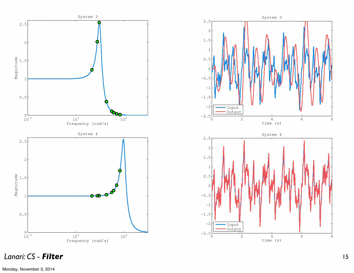
it just shows at whichfrequencies the input
has contributions
Monday, November 3, 2014
Lanari: CS - Filter 12
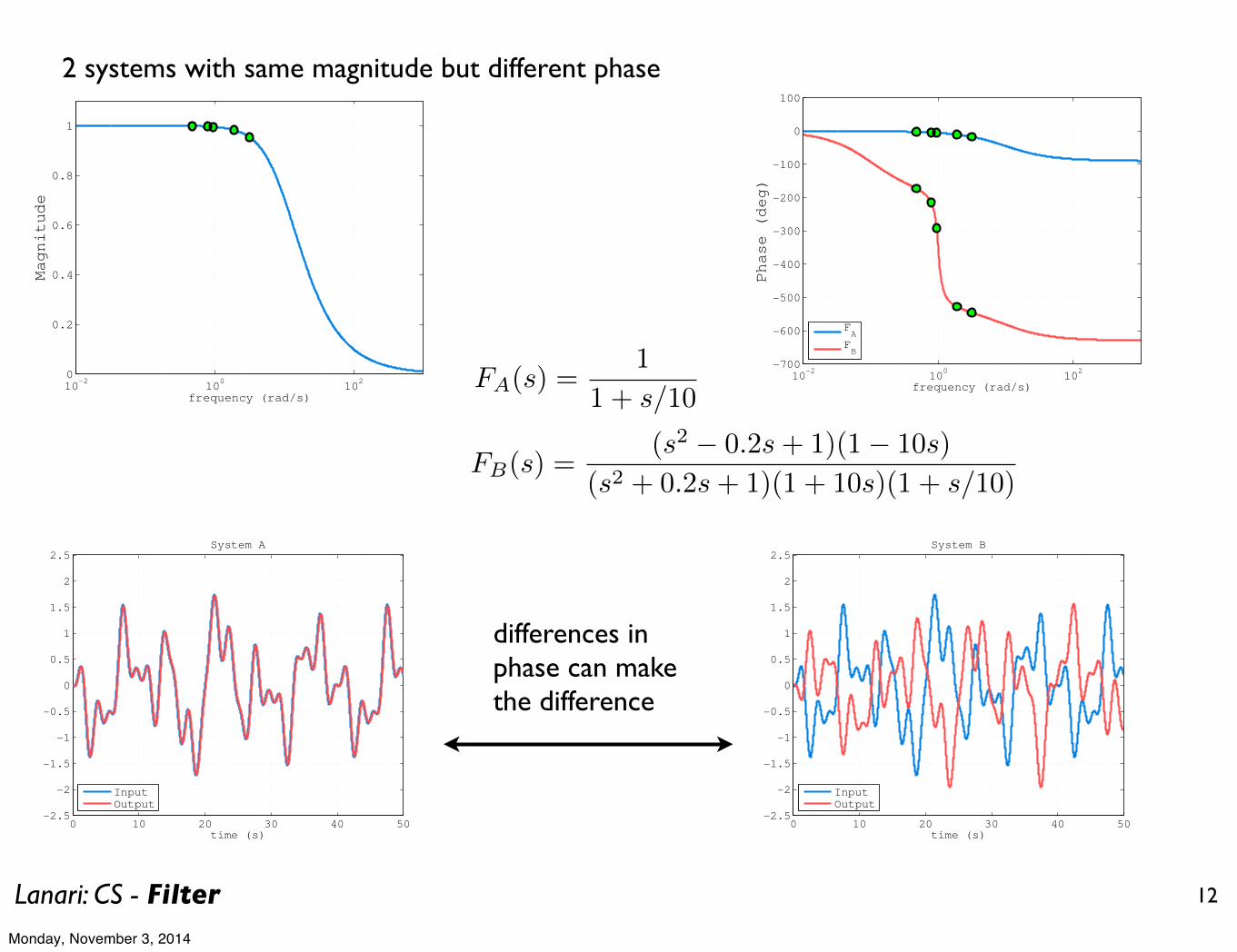
2 systems with same magnitude but different phase
10!2
100
102
0
0.2
0.4
0.6
0.8
1
frequency (rad/s)
Magnitude
10!2
100
102
!700
!600
!500
!400
!300
!200
!100
0
100
Phase (deg)
frequency (rad/s)
FA
FB
0 10 20 30 40 50!2.5
!2
!1.5
!1
!0.5
0
0.5
1
1.5
2
2.5System A
time (s)
InputOutput
0 10 20 30 40 50!2.5
!2
!1.5
!1
!0.5
0
0.5
1
1.5
2
2.5System B
time (s)
InputOutput
FA(s) =1
1 + s/10
FB(s) =(s2 − 0.2s+ 1)(1− 10s)
(s2 + 0.2s+ 1)(1 + 10s)(1 + s/10)
differences in phase can make the difference
Monday, November 3, 2014
Lanari: CS - Filter 13
10!2
100
102
!10
!5
0
5
10
frequency (rad/s)
Magnitude (dB)
F1
F2
F3
F4
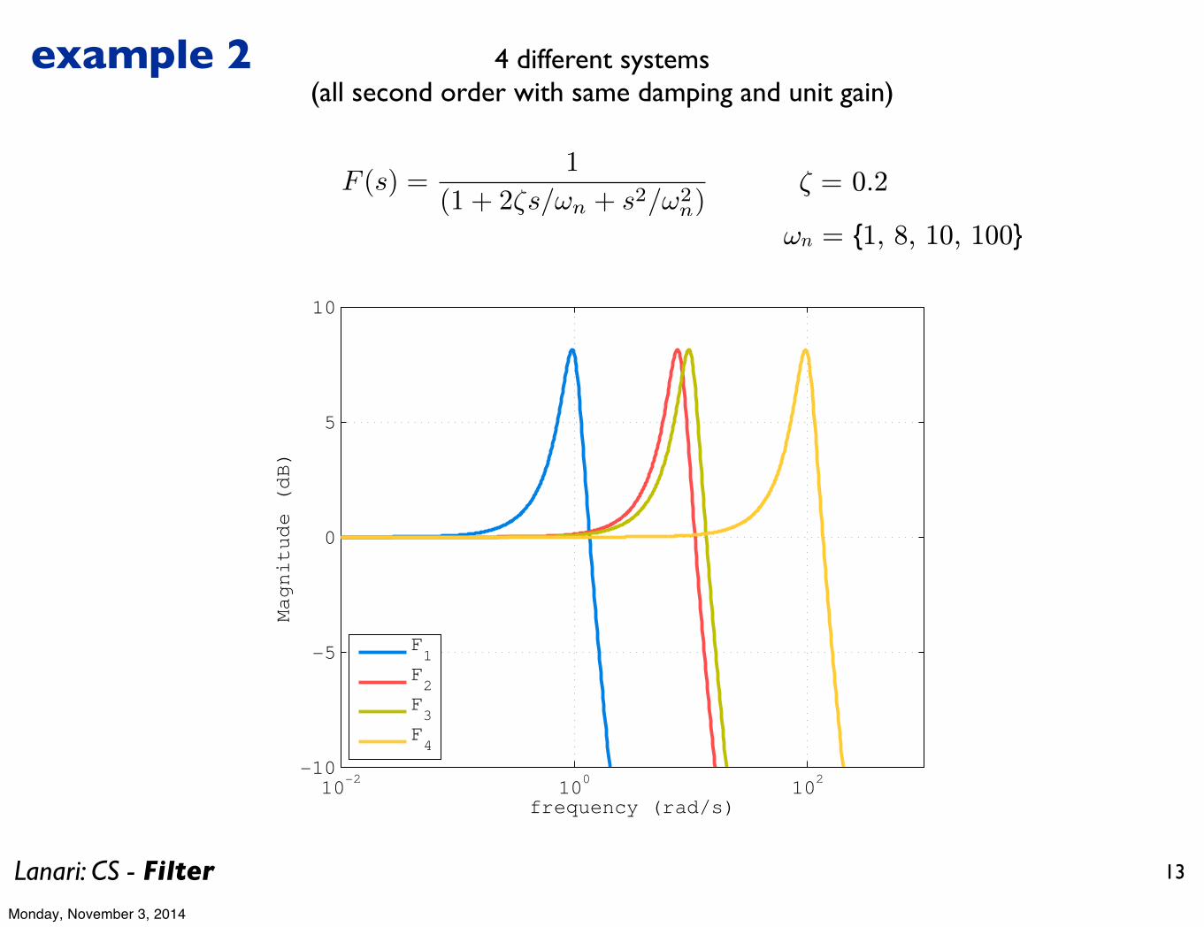
F (s) =1
(1 + 2ζs/ωn + s2/ω2n)
³ = 0.2
!n = {1, 8, 10, 100}
4 different systems(all second order with same damping and unit gain)
example 2
Monday, November 3, 2014

Lanari: CS - Filter 14
0 2 4 6 8!2.5
!2
!1.5
!1
!0.5
0
0.5
1
1.5
2
2.5System 1
time (s)
InputOutput
0 2 4 6 8!2.5
!2
!1.5
!1
!0.5
0
0.5
1
1.5
2
2.5System 2
time (s)
InputOutput
10!2
100
102
0
0.5
1
1.5
2
2.5
frequency (rad/s)
Magnitude
System 1
10!2
100
102
0
0.5
1
1.5
2
2.5
frequency (rad/s)
Magnitude
System 2
Monday, November 3, 2014
Lanari: CS - Filter 15
10!2
100
102
0
0.5
1
1.5
2
2.5
System 3
frequency (rad/s)
Magnitude
0 2 4 6 8!2.5
!2
!1.5
!1
!0.5
0
0.5
1
1.5
2
2.5System 3
time (s)
InputOutput
0 2 4 6 8!2.5
!2
!1.5
!1
!0.5
0
0.5
1
1.5
2
2.5System 4
time (s)
InputOutput
10!2
100
102
0
0.5
1
1.5
2
2.5
frequency (rad/s)
Magnitude
System 4
Monday, November 3, 2014
Lanari: CS - Filter
0 1 2 3 4!3
!2
!1
0
1
2
3System 3
time (s)
yySS
16
0 1 2 3 4!1
!0.5
0
0.5
1System 3 ! transient
time (s)
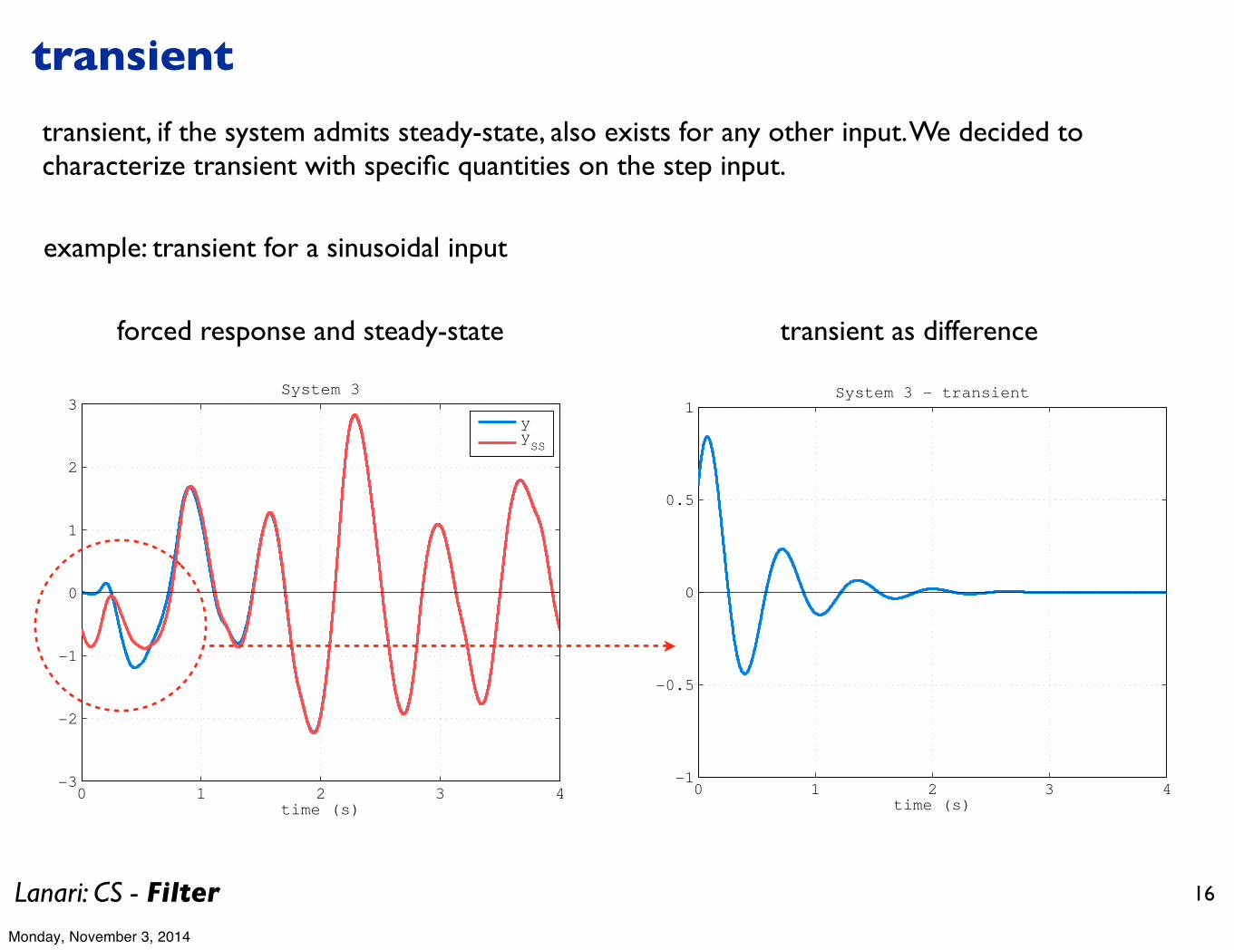
forced response and steady-state transient as difference
transient
transient, if the system admits steady-state, also exists for any other input. We decided to characterize transient with specific quantities on the step input.
example: transient for a sinusoidal input
Monday, November 3, 2014

Lanari: CS - Filter 17
dynamic bass microphone(tailored for kick drum, works well with any low frequency instrument,
low frequency peak at 100 Hz)
a 10.000 € voice microphone ...
electric guitar microphone
microphones
Monday, November 3, 2014

Lanari: CS - Filter 18
Quarter-car suspension model
wheel
body
road
mb
mw
xb
xw
r
ks bs
kt
fs
Model of a quarter part of a car with its wheel and tire
The body with mass mb represents the car chassis connected to the wheel by a passive spring (ks), and a shock absorber represented by a damper (bs).The spring (kt) models the compressibility of the tire pneumatic.
In an active suspension an hydraulic actuator (fs)between the chassis and wheel assembly may help in balancing conflicting objectives as passenger comfort, road handling and suspension deflection.
mbxb + ks(xb − xw) + bs(xb − xw) = fs
mwxw − ks(xb − xw) + bs(xb − xw) + kt(xw − r) = −fs
fs acts on both the body and the wheel assembly
r can be seen as an input affecting the evolution of the system through the tire (disturbance)
Monday, November 3, 2014

Lanari: CS - Filter 19
state vector
several outputs of interest
�xb xb xw xw
�T
C1 =�1 0 0 0
�
C2 =�−ks/mb −bs/mb ks/mb bs/mb
�
body (passenger) position
body (passenger) acceleration
suspension deflectionC3 =�1 0 −1 0
�
two inputs (one, fs, can be controlled, the other is the disturbance r)
by setting one of the two inputs to zero and choosing the output of interest, we have a SISO system with corresponding transfer function
Passenger comfort is associated to small passenger acceleration
Physical limitation of the actuator (limits on maximum displacements) defines a constraint
these are two of the possible outputs
Monday, November 3, 2014

Lanari: CS - Filter 20
150
100
50
0
50
100
To: a
b
100
101
102
200
150
100
50
0
50To
: sd
Magnitude from road disturbace and actuator force (fs) to body acceleration and suspension travel
Frequency (rad/sec)
Mag
nitu
de (d
B)
Input: road disturbance (r)Input: actuator force (fs)
actuator to body accelerationfrequency response magnitude
actuator to suspension deflectionfrequency response magnitude
road to body accelerationfrequency response magnitude
road to suspension deflectionfrequency response magnitude
rattlesnake frequency
tire-hop frequency
Monday, November 3, 2014
Lanari: CS - Filter 21
rattlesnake frequency: pure imaginary zeros in the transfer function from the actuator to the suspension deflection, anti-resonance at 22.97 rad/s
tire-hop frequency: pure imaginary zeros in the transfer function from the actuator to the body acceleration (also from actuator to body position), anti-resonance at 56.27 rad/s
at these frequencies it is difficult to counteract any effect of the road on acceleration or on the suspension deflection
Monday, November 3, 2014