control unit reference manual v3a -...
TRANSCRIPT

Page 1
CONTROL UNIT: REFERENCE MANUAL 1 THE DISPLAY AND REVIEW SCREENS............................................................................................... 3
1.1 The Single Bar-graph Display ................................................................................................................ 4 1.2 The View Multiple Devices Display....................................................................................................... 5
1.2.1 Multiple Bar-graph Display ............................................................................................................ 5 1.2.2 Multiple Device Text Display......................................................................................................... 6
1.3 The System Overview Display ............................................................................................................... 7 1.4 The Graph Data Store Display................................................................................................................ 8 1.5 The View Alarm Log Display ................................................................................................................ 9 1.6 Graphical View of Alarm Levels.......................................................................................................... 10
2 BASIC CONFIGURATION ...................................................................................................................... 11 2.1 Autodetect............................................................................................................................................. 11 2.2 Editing Basic Sensor Settings ............................................................................................................... 12 2.3 Set Time / Date ..................................................................................................................................... 14 2.4 4-20mA Settings ................................................................................................................................... 16
2.4.1 Overview ...................................................................................................................................... 16 2.4.2 Control Unit 4-20mA Outputs ...................................................................................................... 16 2.4.3 Analogue Output Modules............................................................................................................ 18 2.4.4 Local DT990 Sensor 4-20mA Outputs ......................................................................................... 20
2.5 Relay Settings ....................................................................................................................................... 21 2.5.1 Overview ...................................................................................................................................... 21 2.5.2 Control Unit Relays ...................................................................................................................... 21 2.5.3 Relay Output Modules .................................................................................................................. 22 2.5.4 Local DT990 Sensor Relay Outputs ............................................................................................. 24
2.6 Log Rates (Long Term & Short Term Memory) .................................................................................. 26 2.7 More Sensors ........................................................................................................................................ 26
2.7.1 Manually Add Sensors/Devices.................................................................................................... 26 2.7.2 Editing Sensor/Device Settings..................................................................................................... 27 2.7.3 Deleting Sensors/Devices ............................................................................................................. 28 2.7.4 Editing Settings for all Sensors/Devices at once........................................................................... 28
2.8 Other Functions .................................................................................................................................... 28
3 SENSOR SETTINGS ................................................................................................................................. 29 3.1 Setting up Groups ................................................................................................................................. 29 3.2 Calibration Settings .............................................................................................................................. 30 3.3 Sensitivity ............................................................................................................................................. 30 3.4 Alarm Settings ...................................................................................................................................... 31 3.5 Self Test Settings .................................................................................................................................. 31 3.6 Poll Rate ............................................................................................................................................... 31 3.7 Log Options .......................................................................................................................................... 31 3.8 Plant Run Input ..................................................................................................................................... 31 3.9 Clip Level ............................................................................................................................................. 31 3.10 Enabled ................................................................................................................................................. 31 3.11 AIM Channels....................................................................................................................................... 32
4 OTHER FUNCTIONS ............................................................................................................................... 33 4.1 Language .............................................................................................................................................. 33 4.2 Latch Alarms, Fail Safe Relays ............................................................................................................ 33 4.3 Use Modem........................................................................................................................................... 33 4.4 PC Communications ............................................................................................................................. 34 4.5 Set Password......................................................................................................................................... 34 4.6 Reset Functions..................................................................................................................................... 34 4.7 Maintenance Mode ............................................................................................................................... 35 4.8 Sensor Comms mode, Baud Rate, Parity .............................................................................................. 35 4.9 Backlight off ......................................................................................................................................... 35 4.10 Comms Error Delay.............................................................................................................................. 35

Page 2
4.11 Digital Inputs ........................................................................................................................................ 35 4.12 Plant Run / Plant Stop Feature.............................................................................................................. 36 4.13 Multi Cal Factors .................................................................................................................................. 37 4.14 Diagnostics Mode ................................................................................................................................. 38 4.15 Software Version .................................................................................................................................. 38
5 DERIVED CHANNELS............................................................................................................................. 39 5.1.1 Filter.............................................................................................................................................. 39 5.1.2 Fixed Value................................................................................................................................... 39 5.1.3 Mass.............................................................................................................................................. 39 5.1.4 Sum............................................................................................................................................... 40 5.1.5 Dust at STP O2 (Temperature, Pressure, Oxygen, Moisture Compensation) ............................... 40 5.1.6 Totaliser ........................................................................................................................................ 41 5.1.7 Averager ....................................................................................................................................... 41 5.1.8 Change Rate.................................................................................................................................. 41 5.1.9 Max Min ....................................................................................................................................... 41
6 QUALITY ASSURANCE AND SELF TESTS ........................................................................................ 42
7 CALIBRATION.......................................................................................................................................... 43 7.1 Introduction .......................................................................................................................................... 43 7.2 Calculating the Calibration Factor ........................................................................................................ 43 7.3 Calibration Procedure ........................................................................................................................... 43 7.4 Using the Calibration Tool ................................................................................................................... 43
8 MAINTENANCE........................................................................................................................................ 45 8.1 Overview .............................................................................................................................................. 45 8.2 Placing your sensors in Maintenance Mode ......................................................................................... 45
9 MENU MAPS.............................................................................................................................................. 48 9.1 Tool Bar................................................................................................................................................ 48 9.2 Basic Sensor Setup ............................................................................................................................... 49 9.3 More Sensor Settings............................................................................................................................ 50 9.4 Basic System Setup............................................................................................................................... 51 9.5 Other Functions .................................................................................................................................... 52 9.6 QA and Calibration............................................................................................................................... 53
Document Control Information Document Reference No. ...........................................................................CONTROL UNIT _REFERENCE Original Issue Date ............................................................................................................................... 26/2/07 Current Issue No............................................................................................................................................3a Software Version. .......................................................................................................................................7.00 Last Modified on .................................................................................................................................. 1/10/07
Page 3
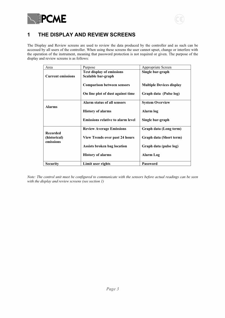
1 THE DISPLAY AND REVIEW SCREENS The Display and Review screens are used to review the data produced by the controller and as such can be accessed by all users of the controller. When using these screens the user cannot upset, change or interfere with the operation of the instrument, meaning that password protection is not required or given. The purpose of the display and review screens is as follows:
Area Purpose Appropriate Screen Current emissions
Text display of emissions Scalable bar-graph Comparison between sensors On line plot of dust against time
Single bar-graph Multiple Devices display Graph data (Pulse log)
Alarms
Alarm status of all sensors History of alarms Emissions relative to alarm level
System Overview Alarm log Single bar-graph
Recorded (historical) emissions
Review Average Emissions View Trends over past 24 hours Assists broken bag location History of alarms
Graph data (Long term) Graph data (Short term) Graph data (pulse log) Alarm Log
Security Limit user rights Password Note: The control unit must be configured to communicate with the sensors before actual readings can be seen with the display and review screens (see section 1)

Page 4
1.1 The Single Bar-graph Display Selecting the ‘View Bar-graph display’ icon from the icon bar will display a screen similar to that shown below.
This ‘View Single Bar-graph’ display provides a convenient means of displaying the emissions on a particular stack. The screen comprises a text display of emissions to the right and a bar graph on the left showing both dust levels and alarm levels (if set). The Bar graph may be manually scaled as required by using the Scale tool. The bar graph and text display may be configured to display instantaneous or average values by using the selector above the bar. A further textual display of the bar-graph value is provided below the bar. The specific Stack may be selected with the Stack Selector control. In applications where channels have been set up with the same stack or group identification these will be displayed together on this screen. (E.g. this is advised in relation to normalisation). In such cases the display will look like:

Page 5
The display can show up to six devices. Each device in the list has a textual display of the instantaneous value. In addition, any device may be selected to be displayed on the bar graph by means of the Device Selector tool.
1.2 The View Multiple Devices Display 1.2.1 Multiple Bar-graph Display Selecting the ‘View Multiple Devices’ icon from the icon bar will display a screen similar to that shown below. In this case the Stack identifications have already been changed. (See section 3.3)
This display allows multiple devices to be displayed as a bar graph with a textual value below. The screen can display four bar-graphs and further bar graphs may be viewed in ‘pages’ of four by use of the Next Page & Previous Page tools. The area above each bar shows the Stack & Device Name and each bar may be set to display either instantaneous or average values. Each bar graph may be independently scaled by use of the Scale Tool. When alarms have been set for a device, the alarm thresholds are marked on the bar graph. Select the Text icon to switch to the textual listing display (see the next section for details of the textual display).

Page 6
1.2.2 Multiple Device Text Display Selecting the ‘Text’ icon from the View Multiple Devices screen will display a screen similar to that shown below:
This display provides a scrollable list of all devices with instantaneous values and display units. The screen can display up to nine devices simultaneously and further devices may be shown by using the Scroll Bar. To return to the Bar-graph display, select the Change Display tool or, alternatively, move to another display by using the icon bar.

Page 7
1.3 The System Overview Display Selecting the ‘System Overview’ icon from the icon bar will display a screen similar to that shown below:
This display provides a summary table and shows the alarm status of all sensors. The table is dynamically re-sized to accommodate the number of installed sensors. When any device has an active alarm, the relevant cell within the table will begin to flash and show ‘ALARM’. When no alarms exist, the cells will be normal (i.e. not flashing) and will show ‘OK’. The cell will read ‘—‘ if no sensors have been allocated to the group name of the cell. The user may select any cell to be automatically linked to the ‘View Single Group’ display for the chosen group. (Scroll between cells using the Up and Down arrows). This allows rapid analysis of the cause of the alarm condition as details for all devices within the group are displayed within the view single group display. The example above shows a controller with four sensors. The stack ‘MillStackB’ has a device with an alarm condition; all other devices are operating normally. The Status Bar at the bottom of the screen also provides details of all alarm activity for any device.
Page 8
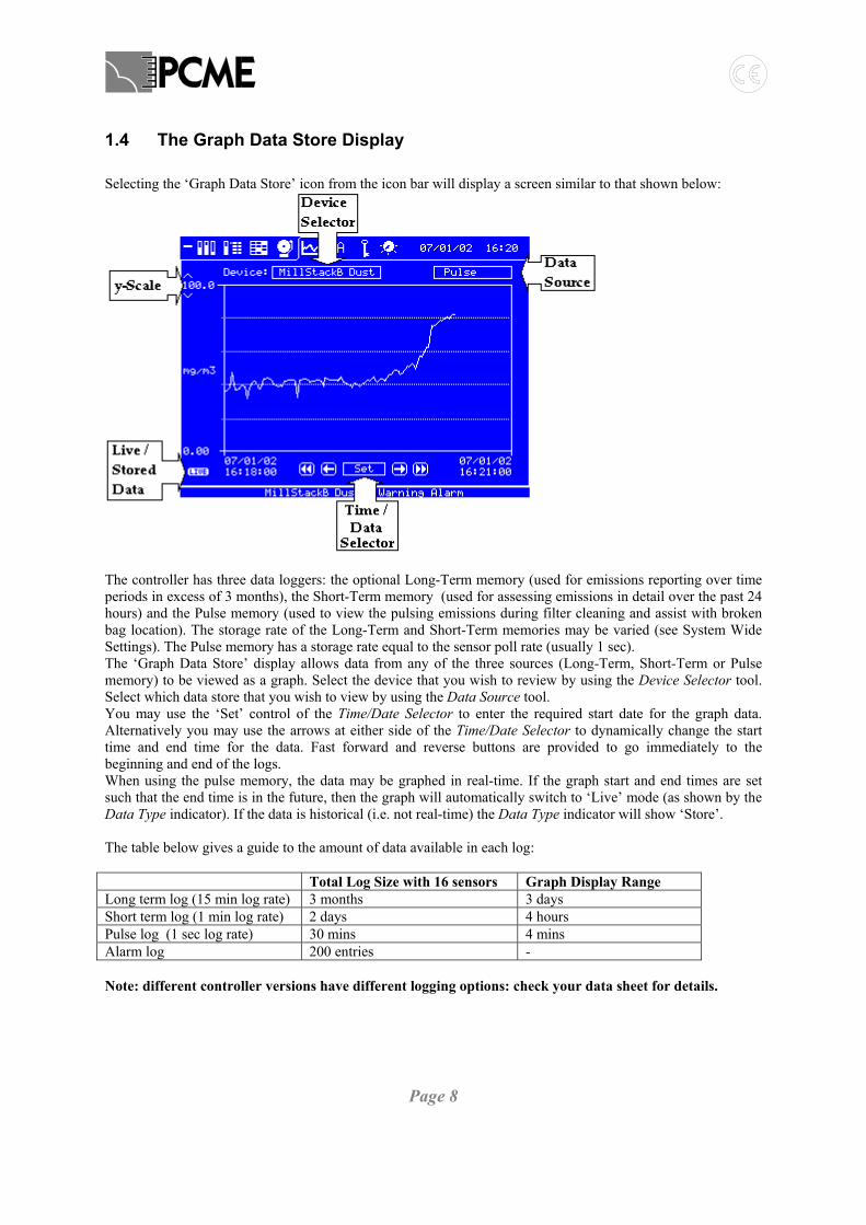
1.4 The Graph Data Store Display Selecting the ‘Graph Data Store’ icon from the icon bar will display a screen similar to that shown below:
The controller has three data loggers: the optional Long-Term memory (used for emissions reporting over time periods in excess of 3 months), the Short-Term memory (used for assessing emissions in detail over the past 24 hours) and the Pulse memory (used to view the pulsing emissions during filter cleaning and assist with broken bag location). The storage rate of the Long-Term and Short-Term memories may be varied (see System Wide Settings). The Pulse memory has a storage rate equal to the sensor poll rate (usually 1 sec). The ‘Graph Data Store’ display allows data from any of the three sources (Long-Term, Short-Term or Pulse memory) to be viewed as a graph. Select the device that you wish to review by using the Device Selector tool. Select which data store that you wish to view by using the Data Source tool. You may use the ‘Set’ control of the Time/Date Selector to enter the required start date for the graph data. Alternatively you may use the arrows at either side of the Time/Date Selector to dynamically change the start time and end time for the data. Fast forward and reverse buttons are provided to go immediately to the beginning and end of the logs. When using the pulse memory, the data may be graphed in real-time. If the graph start and end times are set such that the end time is in the future, then the graph will automatically switch to ‘Live’ mode (as shown by the Data Type indicator). If the data is historical (i.e. not real-time) the Data Type indicator will show ‘Store’. The table below gives a guide to the amount of data available in each log: Total Log Size with 16 sensors Graph Display Range Long term log (15 min log rate) 3 months 3 days Short term log (1 min log rate) 2 days 4 hours Pulse log (1 sec log rate) 30 mins 4 mins Alarm log 200 entries - Note: different controller versions have different logging options: check your data sheet for details.

Page 9
1.5 The View Alarm Log Display Selecting the ‘Alarm Log’ icon from the icon bar will display a screen similar to that shown below:
This display provides a scrollable list of logged alarm events for all devices. Each alarm event is identified with a stack name, device name, alarm type (Limit, Warning etc.), start date/time and duration. The value of the sensor reading at the time the alarm is triggered and the level at which the alarm is set are also displayed. Active alarms are shown as ACTIVE within the log entry. If the list exceeds the screen limit of 6 events, the Scroll tools may be used to move through the list as required. If the Alarm Latching facility is in use, alarms that become inactive will be marked LATCHED. Latched Alarms that are now inactive may be reset by pressing the Reset Latched Alarms button. The meaning of the different alarm types is explained in the table below: Alarm Type Meaning Warning Alarm Early warning alarm (High alarm) threshold exceeded based on instantaneous emissions Limit Alarm Plant shut down alarm (High High alarm) threshold exceeded based on instantaneous emissions Ave Warning Alm Early warning alarm (High alarm) threshold exceeded based on average emissions Ave Limit Alm Plant shut down alarm (High High alarm) threshold exceeded based on average emissions Low Alarms Some sensors provide equivalent Low alarm threshold to detect the dropping of emission or
flow levels, which may indicate a blockage. No Response The sensor has failed to respond: check your wiring and/or modbus address settings Value Corrupt Some other communication failure to the sensor has occurred Pwr Interrupt Power lost to the Control Unit for the specified period Zero Fault Span Fault
A sensor has failed one of its self tests and may be faulty.
Clean Probe A sensor has failed its contamination check and may need cleaning Note: Self test alarms are only available on certain sensor types.

Page 10
1.6 Graphical View of Alarm Levels The Warning and Limit alarms levels for each channel are displayed graphically on all bar graph displays as shown below. The Warning Alarm level is marked W. The Limit Alarm level is marked L. The selector above the bar graph allows you to switch display between an instantaneous reading (marked INSTANT) and an average reading (marked AVERAGE). You can set up independent alarm levels for the instantaneous reading and the average reading.
Note: the 220 sensor displays readings as a percentage of the limit alarm level. It is not possible to set an alarm level in mg/m3.

Page 11
2 BASIC CONFIGURATION This section describes the functions available on the Setup screen.
Autodetect
Sensor Setup
----- Time / Date
----- 4-20mA Settings
----- Relay Settings
----- Log rates
More Settings Other Functions
System Setup
www.pcme.co.uk 7.00
2.1 Autodetect The Autodetect function is designed to provide ‘plug and play’ setup for the control unit:
1. Complete the electrical installation (see Installation Reference manual) 2. Switch on the external power supply to the unit – the Configure screen will be displayed. 3. Press the Down key to highlight Autodetect 4. Press the Enter key to run Autodetect.
Scan adr 15 - found 3
Address 1 Device : DT990Address 2 Device: DT990Address 3 Device: AOM
Download Stack1 Dust21%
AutodetectSensor Setup
----- Time / Date
----- 4-20mA Settings
----- Relay Settings
----- Log Rates
More Settings Other Functions
System Setup
www.pcme.co.u k 7.01
The autodetect should detect all sensors /devices attached to the modbus RS485 network. The following are automatically setup for each sensor:
Page 12
1. A display channel (bar graph or text display. Select Bar/Text to switch between bar graph and text display).
2. Download default settings to the sensor (uncalibrated - calibration factor = 1). 3. A 4-20mAoutput signal from the control unit. 4. Logging in the control unit.
The following notes explain the Autodetect Function in more detail.
1. The controller scans in order all the modbus addresses in the range 1-32. It then adds display channels in this order. It is possible to use the PC Configuration software to later adjust this display order. Alternatively the sensors can be added manually (see the More Sensors section).
2. If the controller is being re-configured, all existing settings can be cleared first by performing a ‘Master Reset’. Menu Route: Setup Page: Other Function->Reset Functions->Master Reset.
3. If new sensors are add to the network it is possible to rerun autodetect without doing a Master Reset. Display channels for newly detected modbus addresses will be added to the existing list of channels. Configuration settings and logging for the existing channels are unaffected.
4. Some devices (e.g. the AIM) are not recognised by the Autodetect. The device type will be displayed as unknown. These sensors must be added manually.
5. If the Autodetect fails to detect any or all of your sensors follow the guidelines in the trouble shooting section.
6. The detected channels are given default names Stack1 Dust, Stack2 Dust, Stack3 Dust etc. based on the modbus address values. A new group is created for each sensor on the Overview page. It is possible to later change the grouping of sensors. See the More Sensors section for details.
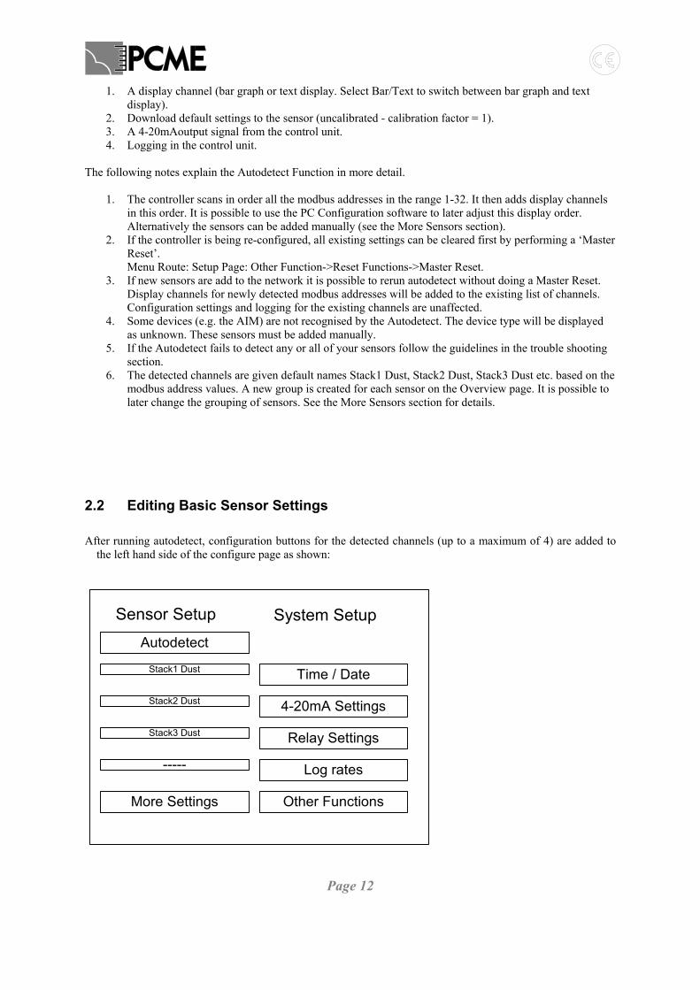
2.2 Editing Basic Sensor Settings After running autodetect, configuration buttons for the detected channels (up to a maximum of 4) are added to
the left hand side of the configure page as shown:
Autodetect
Sensor Setup
Stack1 Dust Time / Date
Stack2 Dust 4-20mA Settings
Stack3 Dust Relay Settings
----- Log rates
More Settings Other Functions
System Setup
Page 13
These buttons provide a basic configuration menu. More advanced settings (and additional sensors) are accessed through the ‘More Sensors’ button.
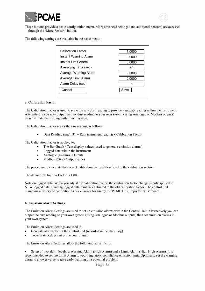
The following settings are available in the basic menu: a. Calibration Factor The Calibration Factor is used to scale the raw dust reading to provide a mg/m3 reading within the instrument. Alternatively you may output the raw dust reading to your own system (using Analogue or Modbus outputs) then calibrate the reading within your system. The Calibration Factor scales the raw reading as follows:
• Dust Reading (mg/m3) = Raw instrument reading x Calibration Factor The Calibration Factor is applied to:
• The Bar Graph / Text display values (used to generate emission alarms) • Logged data within the instrument • Analogue (4-20mA) Outputs • Modbus RS485 Output values
The procedure to calculate the correct calibration factor is described in the calibration section. The default Calibration Factor is 1.00. Note on logged data: When you adjust the calibration factor, the calibration factor change is only applied to NEW logged data. Existing logged data remains calibrated to the old calibration factor. The control unit maintains a history of calibration factor changes for use by the PCME Dust Reporter PC software. b. Emission Alarm Settings The Emission Alarm Settings are used to set up emission alarms within the Control Unit. Alternatively you can output the dust reading to your own system (using Analogue or Modbus outputs) then set emission alarms in your own system. The Emission Alarm Settings are used to: • Generate alarms within the control unit (recorded in the alarm log) • To activate Relays out of the control unit. The Emission Alarm Settings allow the following adjustments: • Setup of two alarm levels: a Warning Alarm (High Alarm) and a Limit Alarm (High High Alarm). It is recommended to set the Limit Alarm to your regulatory compliance emission limit. Optionally set the warning alarm to a lower value to give early warning of a potential problem.
1.00000.00000.0000
600.00000.0000
5
Calibration FactorInstant Warning AlarmInstant Limit AlarmAveraging Time (sec)Average Warning AlarmAverage Limit AlarmAlarm Delay (sec)
Cancel Save

Page 14
• Option to setup either Instant Alarms or Average Alarms. Instant Alarms use the pulse reading read from the sensor (usually once every second).
Average Alarms use a smoothed reading by averaging data based on the Averaging Time. For regulatory compliance it is recommended to set up only the Average Alarm with the Averaging Time set the to the averaging time specified in your regulation. Typical values are:
30 mins = 1800 secs 1 hour = 3600 secs
Instant alarms should only be used if you require to detect quickly a sudden change in dust reading.
To disable any of the alarm levels set the value = 0.00. • Alarm Delay: the alarm delay is used to prevent a temporary high dust spikes from generating unnecessary alarms. Dust spikes are typically generated at process start up or by bag filters cleaning. The default Alarm Delay is set to 5 secs. Increase this as required to the duration of the dust spikes you are seeing (look at the pulse log to access this). Note: the alarm delay is applied to both instant and average alarms. Notes: 1. Averaging is done using a walking window filter. This means the average values used to generate alarms
may differ from the averaged logged data which uses simple averaging. 2. The averaging filter is reset at power up and after making sensor setting adjustments. During the initial
period the reading will be an average of a shorter period than the averaging time. This may result in unwanted alarms.
2.3 Set Time / Date Set the Time /Date for use by the logging functions within the controller.
WARNING Time adjustmentsmay lose logged data!
09 36 03
20 04 03
::
/ /
• WARNING: Changing the time / date may result in loss of logged data • The system does not automatically change the time for daylight saving hours (clocks forward or back). Use the cursor keys to highlight the parameter to be changed and the enter key to change the value. To save the changes and return to the main menu select the Clock icon on the top left of the screen. Notes:

Page 15
1. If the time is set back the Controller will not log new data until the time has passed the latest timestamp in the log.(i.e. if the time is put vack 1 hour from 10.00 ot 09.00 the Controller will not log data unitl the time reaches 10.00. If the time is put back by more than 24 hours the Controller will Clear all logs and start logging again immediately).

Page 16
2.4 4-20mA Settings The AutoDetect procedure will automatically assign the detect sensor channels to 4-20mA outputs within the control unit (scaled 0->100 mg/m3). The 4-20mA Settings function allows you to: • Re-scale the 4-20mA outputs • Apply filtering to the 4-20mA outputs • Reassign the 4-20mA outputs (both within the control unit and from additional Analogue Output Modules) • Fine tune (calibrate) the 4mA and 20mA levels of the outputs. 2.4.1 Overview The Multi Controller has four independent 4-20mA outputs (The Interface Module has a single 4-20mA output). These outputs may be user assigned to any sensor in the network as required. Additional 4-20mA outputs can be supplied by including one or more Analogue Output Modules (AOM) at any point in the sensor network (8 outputs per module). Alternatively an optional 4-20mA output board may be added to the DT990 sensor to provide a local 4-20mA output. Number of outputs Multicontroller Interface Module
4 1
See subsection 2
Analogue Output Module (AOM) 8 See subsection 3 DT990 Option board 1 See subsection 4 2.4.2 Control Unit 4-20mA Outputs Specification • Isolated outputs • Max loading: 250 Ohms • Update rate: 1 sec Setting the 4-20mA scaling and filtering To adjust the outputs go to the Configure Screen and select 4-20mA Settings. When you first enter the 4-20mA Settings Screen the display is as shown below:
Zero
4-20mA Settings
Device
1
2
3
None Selected
None Selected
None Selected
Back
Span Filter (secs)
4 None Selected
0.000 100.0 0001
0.000
0.000
0.000
100.0
100.0
100.0
0001
0001
0001
Calibration
The four rows in the table correspond to outputs 1, 2, 3 & 4. To assign a sensor to an output, select the group and name box then pick the required sensor from the device list. The zero, span and filter may then be changed as required: Zero: The displayed reading corresponding to 4mA output. Factory setting is 0.000.

Page 17
Span: The displayed reading corresponding to 20mA output. Factory setting is 100. Filter: The time constant in seconds of the smoothing applied to the 4-20mA output. Factory setting is 0001. Example: the example below shows Output 1 set up to output Stack1 Dust readings in the range 0 to 50 with no additional filtering applied. Output 2 is set up to output Stack 3 Dust readings between 20 and 40 with a 30 second filter applied. So if Stack1 Dust = 25mg/m3 then output 1 = 4 + 25/50 * (20-4) = 4 + 8 = 12mA. if Stack3 Dust = 25mg/m3 then output 2 = 4 + (25-20)/(40-20) *(20-4) = 4 + 4 = 8mA.
Zero
4-20mA Settings
Device
1
2
3
Stack1 Dust
Stack3 Dust
None Selected
Back
Span Filter (secs)
4 None Selected
0.000 50.00 0001
20.00
0.000
0.000
40.00
100.0
100.0
0030
0001
0001
Calibration
Testing and Calibration of the 4-20mA outputs You can test the 4-20mA outputs are generating the correct current by selecting the Calibration button from the main 4-20mA Settings screen.
4 -2 0 m A C a lib ra t io n
S e le c t C h a n n e l
B a c k
1
S ta rt 4 m A T e st
In c re a se C u rre n t D e c re a se C u rre n t
D ig ita l V a lu e 0 6 6 5
S ta rt 2 0 m A T e st
In c re a se C u rre n t D e c re a se C u rre n t
D ig ita l V a lu e 3 3 7 3
Select the output you wish to test. Attach a multimeter to the output. Select the Start 4mA Test button. The multimeter should display a current of 4mA. If the current is less than 4mA repeatedly select Increase Current until a 4mA reading is reached. If the current is greater than 4mA repeatedly select Decrease Current until a 4mA reading is reached. Similarly select Start 20mA Test.
Page 18
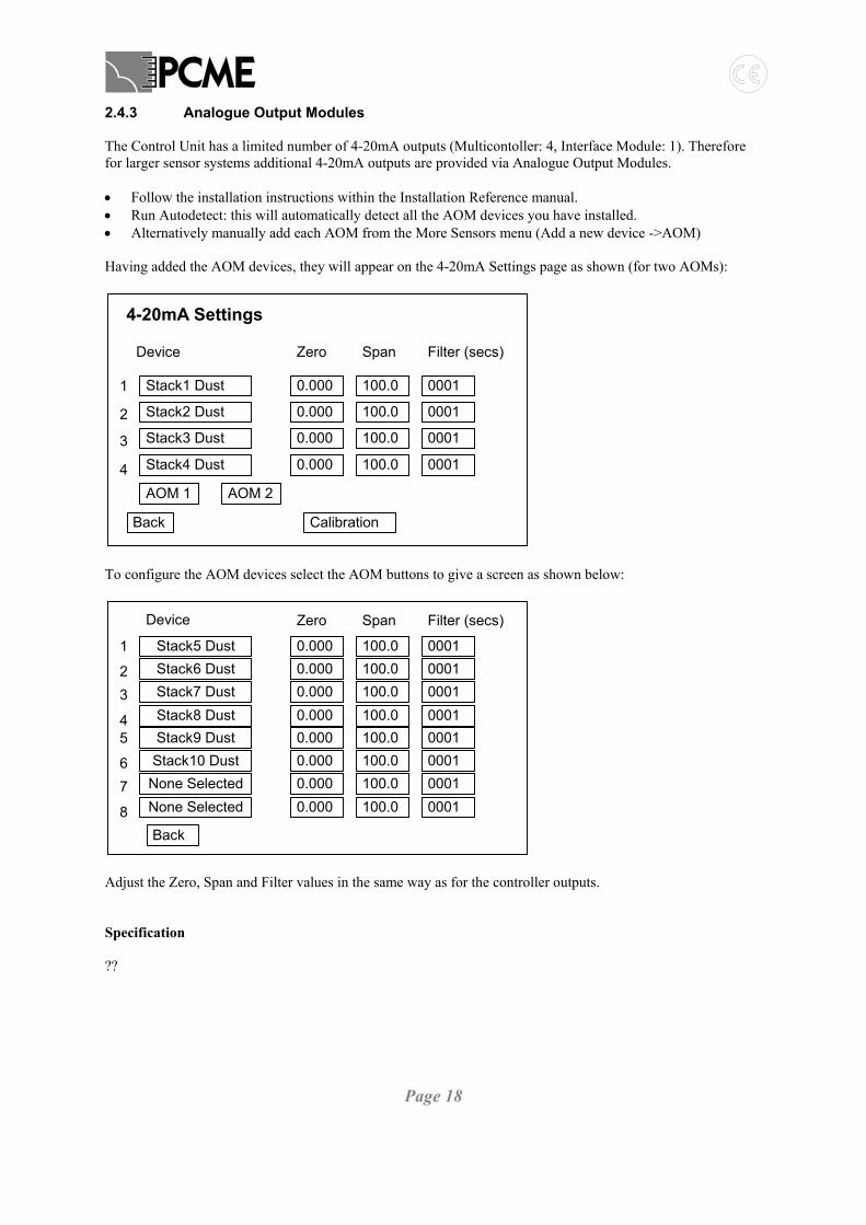
2.4.3 Analogue Output Modules The Control Unit has a limited number of 4-20mA outputs (Multicontoller: 4, Interface Module: 1). Therefore for larger sensor systems additional 4-20mA outputs are provided via Analogue Output Modules. • Follow the installation instructions within the Installation Reference manual. • Run Autodetect: this will automatically detect all the AOM devices you have installed. • Alternatively manually add each AOM from the More Sensors menu (Add a new device ->AOM) Having added the AOM devices, they will appear on the 4-20mA Settings page as shown (for two AOMs):
Zero
4-20mA Settings
Device
1
2
3
Stack1 Dust
Stack2 Dust
Stack3 Dust
Back
Span Filter (secs)
4 Stack4 Dust
0.000 100.0 0001
0.000
0.000
0.000
100.0
100.0
100.0
0001
0001
0001
Calibration
AOM 1 AOM 2
To configure the AOM devices select the AOM buttons to give a screen as shown below:
Zero
1
23
Stack5 DustStack6 DustStack7 Dust
Back
Device Span Filter (secs)
4 Stack8 Dust
0.000 100.0 00010.0000.0000.000
100.0100.0100.0
000100010001
5
67
Stack9 DustStack10 Dust
None Selected
8 None Selected
0.000 100.0 00010.0000.0000.000
100.0100.0100.0
000100010001
Adjust the Zero, Span and Filter values in the same way as for the controller outputs. Specification ??
Page 19
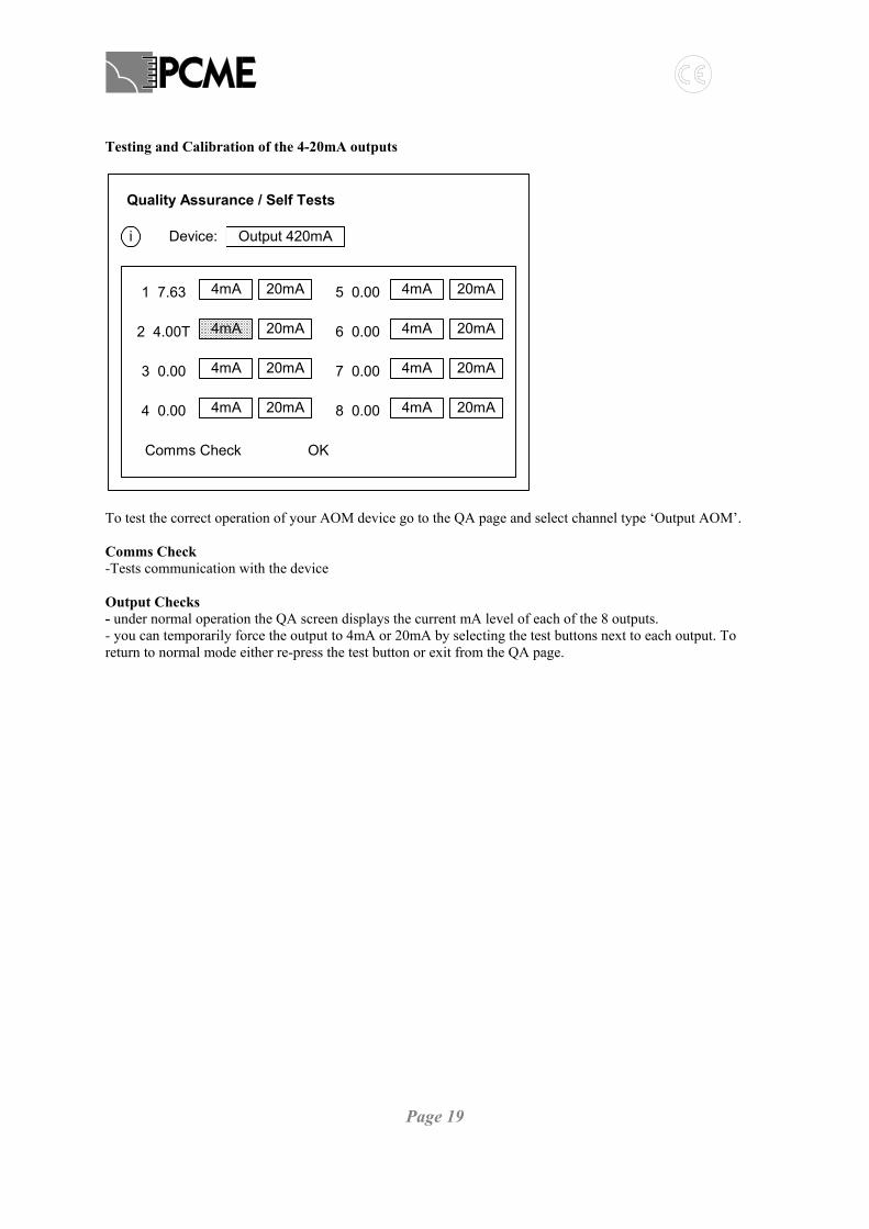
Testing and Calibration of the 4-20mA outputs
Quality Assurance / Self Tests
Output 420mADevice:i
Comms Check OK
1 7.63 4mA 20mA 5 0.00 4mA 20mA
2 4.00T 4mA 20mA 6 0.00 4mA 20mA
3 0.00 4mA 20mA 7 0.00 4mA 20mA
4 0.00 4mA 20mA 8 0.00 4mA 20mA
To test the correct operation of your AOM device go to the QA page and select channel type ‘Output AOM’. Comms Check -Tests communication with the device
Output Checks - under normal operation the QA screen displays the current mA level of each of the 8 outputs. - you can temporarily force the output to 4mA or 20mA by selecting the test buttons next to each output. To return to normal mode either re-press the test button or exit from the QA page.
Page 20
2.4.4 Local DT990 Sensor 4-20mA Outputs Specification • Isolated outputs (1kV isolation) • Max Loading: 500 Ohms • Update rate: 0.2 secs Setting the 4-20mA scaling and filtering To adjust the local DT990 sensor output go to the Configure Screen, select More Sensors, Edit an Existing device and select the required sensor. Set the following settings: Local 4-20mA Zero: sets the 4mA level Local 4-20mA Span : sets the 20mA level Local 4-20mA Filter (s): sets the filter time (walking window filter) applied to the instantaneous output. The default setting is to read between 0 and 100 units with a filter time of 10 secs. Testing and Calibration of the 4-20mA outputs No function is provided to test or calibrate the local DT990 sensor 4-20mA output from the control unit.

Page 21
2.5 Relay Settings The Relays Settings function allows you to assign the usage of the alarm relay both within the control unit and from additional Relay Output Modules. 2.5.1 Overview The Multi Controller has four Relay outputs (The Interface Module has two Relay output). Additional Relay outputs can be supplied by including one or more Relay Output Modules (ROM) at any point in the sensor network (8 outputs per module). Alternatively an optional output board may be added to the DT990 sensor to provide a local relay output. Number of outputs Multicontroller Interface Module
4 2
See subsection 2
Relay Output Module (ROM) 8 See subsection 3 DT990 Option board 1 See subsection 4 2.5.2 Control Unit Relays Specification • Volt free SPCO contacts • Current rating 3A • May be used to switch mains voltages • Option to wire Normal Open or Normally Closed • Option to run in Failsafe or non-Failsafe mode (default non-Failsafe). • Activation response time: 1 sec (increased to 200ms by increasing poll rate) Assignment of Relays The default use of the relays is defined in the table below: Relay 1 Comms Alarm (e.g. caused by faulty wiring to a sensor) Relay 2 Limit Alarm from any channel/sensor (either Instantaneous or Average) Relay 3 Warning Alarm from any channel/sensor (either Instantaneous or Average) Relay 4 Self Test Fail Alarm (e.g. caused by contamination of a sensor) Note: only the first two relays are available in the Interface Module Note: self test alarms are only available with certain sensor types. By default these settings are global to all channels: e.g. relay 2 will trigger if any channel goes into Limit Alarm. It is possible to assign the relays to individual channels/sensors and the user to specify the alarm types. See the examples below:

Page 22
Relay Settings
Alarm Type
1
2
3
Comms Error
Limit Alarm
Warning Alarm
Back
4 Self Test Fail
All devices
All devices
All devices
All devices
Device
Relay Settings
Alarm Type
1
2
3
Limit Alarm
Limit Alarm
Limit Alarm
Back
4 Limit Alarm
Stack 1 Dust
Stack 2 Dust
Stack 3 Dust
Stack 4 Dust
Device
The list below shows the full set of Alarm Types available: Warning Alarm Limit Alarm Comms Error Self Test Fail Test Running Maintenance Zero/Span Fail Contam Fail Latch Alarms Use Latch Alarm if you need the alarm relays to stay latched after the end of an alarm condition. To set Latch Alarms go to Other Functions and check ‘Latch Alarms?’ Latched alarms will remain active until cancelled by the operator. This is done from the ‘Reset Latched Alarms’ button on the Event Log page. Fail-Safe Relays Put relays in Fail Safe mode if you need the relays to indicate Power Failure to the control unit. By default, the relays are non Fail-Safe. To put the relays in Fail-Safe mode go to Other Functions and check ‘Failsafe Relays?’ Details of operation: In non-Failsafe mode, during normal non-alarm conditions the relays are unenergised; during alarm conditions the relays become energised. In Failsafe mode the operation is reversed: during normal non-alarm conditions the relays are energised; during alarm conditions the relays are unenergised. Thus power loss to the Control Unit will unenergise the relay and generate an alarm. 2.5.3 Relay Output Modules The Control Unit has a limited number of relay outputs (Multicontoller: 4, Interface Module: 2). Therefore for larger sensor systems additional relay outputs are provided via Relay Output Modules. • Follow the installation instructions within the Installation Reference manual.
Page 23
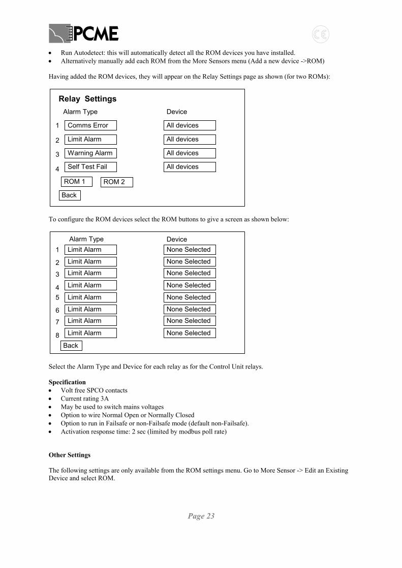
• Run Autodetect: this will automatically detect all the ROM devices you have installed. • Alternatively manually add each ROM from the More Sensors menu (Add a new device ->ROM) Having added the ROM devices, they will appear on the Relay Settings page as shown (for two ROMs):
Relay SettingsAlarm Type
1
2
3
Comms Error
Limit Alarm
Warning Alarm
Back
4 Self Test Fail
All devices
All devices
All devices
All devices
Device
ROM 1 ROM 2
To configure the ROM devices select the ROM buttons to give a screen as shown below:
Alarm Type1
2
3
Limit Alarm
Limit Alarm
Limit Alarm
Back
4 Limit Alarm
None Selected
None Selected
None Selected
None Selected
Device
5
6
7
Limit Alarm
Limit Alarm
Limit Alarm
8 Limit Alarm
None Selected
None Selected
None Selected
None Selected
Select the Alarm Type and Device for each relay as for the Control Unit relays. Specification • Volt free SPCO contacts • Current rating 3A • May be used to switch mains voltages • Option to wire Normal Open or Normally Closed • Option to run in Failsafe or non-Failsafe mode (default non-Failsafe). • Activation response time: 2 sec (limited by modbus poll rate) Other Settings The following settings are only available from the ROM settings menu. Go to More Sensor -> Edit an Existing Device and select ROM.

Page 24
o Latch Alarms? : If this is set to Yes the alarm relays will stay latched on after the alarm condition has cleared. To reset latched alarms go to the Event Log screen in your control unit and press the Reset Latched Alarms button.
Note: for the latched alarms function to work you must also check the Latch Alarms option in the System Wide Settings in your control unit. o Fail Safe Relays? : If this is set to Yes the relays will be energised in the non-alarm state and become non-
energised when in alarm. In this mode you can detect for power failure. Note: the Fail Safe operation only detects a power failure to the ROM device. It does not detect a communication failure with the control unit. You should monitor for this by setting up a fail-safe relay within your control unit to monitor for comms errors. Testing the ROM devices
Quality Assurance / Self Tests
Output RelayDevice:i
Comms Check OK
Relay 1 OFF Test Relay 5 OFF Test
Relay 2 ON Test Relay 6 OFF Test
Relay 3 OFF Test Relay 7 OFF Test
Relay 4 OFF Test Relay 8 OFF Test
To test the correct operation of your ROM device go to the QA page in the control unit and select Device: Output Relay. Comms Check -tests communication with the device
Output Checks - under normal operation the QA screen displays the current state of each of the 8 outputs. You can also check the current state of the relays by checking the LEDs in the device itself. - you can temporarily force the relays ON by selecting the test buttons next to each relay. You need to keep your finger on the select key to sustain the test. 2.5.4 Local DT990 Sensor Relay Outputs Specification • volt-free DPCO relay • current rating 1Amp per contact • DO NOT switch mains voltage! The PCB tracks and connector are NOT mains rated. • option to wire normally open or normally closed • non fail-safe operation only

Page 25
Setting the 4-20mA scaling and filtering To adjust the local DT990 relay output go to the Configure Screen, select More Sensors, Edit an Existing device and select the required sensor. Set the following settings: • Local Relay Source: select which of the alarms trigger the local relay : none, the instantaneous alarm only,
the average alarm only or both. • Local Relay Level: specify whether the local alarm relays are triggered on reaching the Warning Level or
Limit Level of the alarm. • The default settings for the local alarm relays are to be triggered by Both Limit alarms. Notes: it is not possible to latch the relays. It is not possible to run the relays in fail-safe mode Testing and Calibration of the 4-20mA outputs No function is provided to test or calibrate the local DT990 sensor relay output from the control unit.

Page 26
2.6 Log Rates (Long Term & Short Term Memory) The Log Rates option allows the storage rate for the long-term memory and the short-term memory to be viewed or changed. Select the ‘Log Rates’ option then select Long Term or Short Term as required. The Long Term memory may be set to log at any interval from 1 to 120 minutes. The short-term memory may be set to log at any interval from 10 to 240 seconds. Notes: These Log Rates apply equally to all installed sensors and channels which have logging enabled. The Pulse Log is logged at the Poll Rate specific to individual sensors/channels. See the sections on Configuring Sensors. Default Log Rates: Available Log Rates:
2.7 More Sensors Basic Sensor Settings (e.g. Calibration factors and Alarm Levels) may be set from the main configure page (see Section 2.2. Use the More Sensors menu to make further changes to your sensor settings or to manual Add or Delete sensors. Route: Configure Page -> More Sensors.
Add a new device
Sensor Configuration
Edit an existing device
Delete an existing device
Edit All Devices
Back
2.7.1 Manually Add Sensors/Devices The manual mode is used to add sensors when: • Manual control of the order in which the devices are displayed is required • Only specific sensors are to be added To add a sensor: • Menu Route: ‘Setup’ display -> More Settings -> Add a New Device • Choose the correct channel type from the list and set the following parameters:
o Modbus Address: set to the address set on the sensor dip switches
15Long T erm (m ins)
S hort T erm (secs)
B ack
60
1Long Term (mins)
Short Term (secs)
2 5 10 15 30 60 120 240
10 15 20 30 60 120 240
Page 27
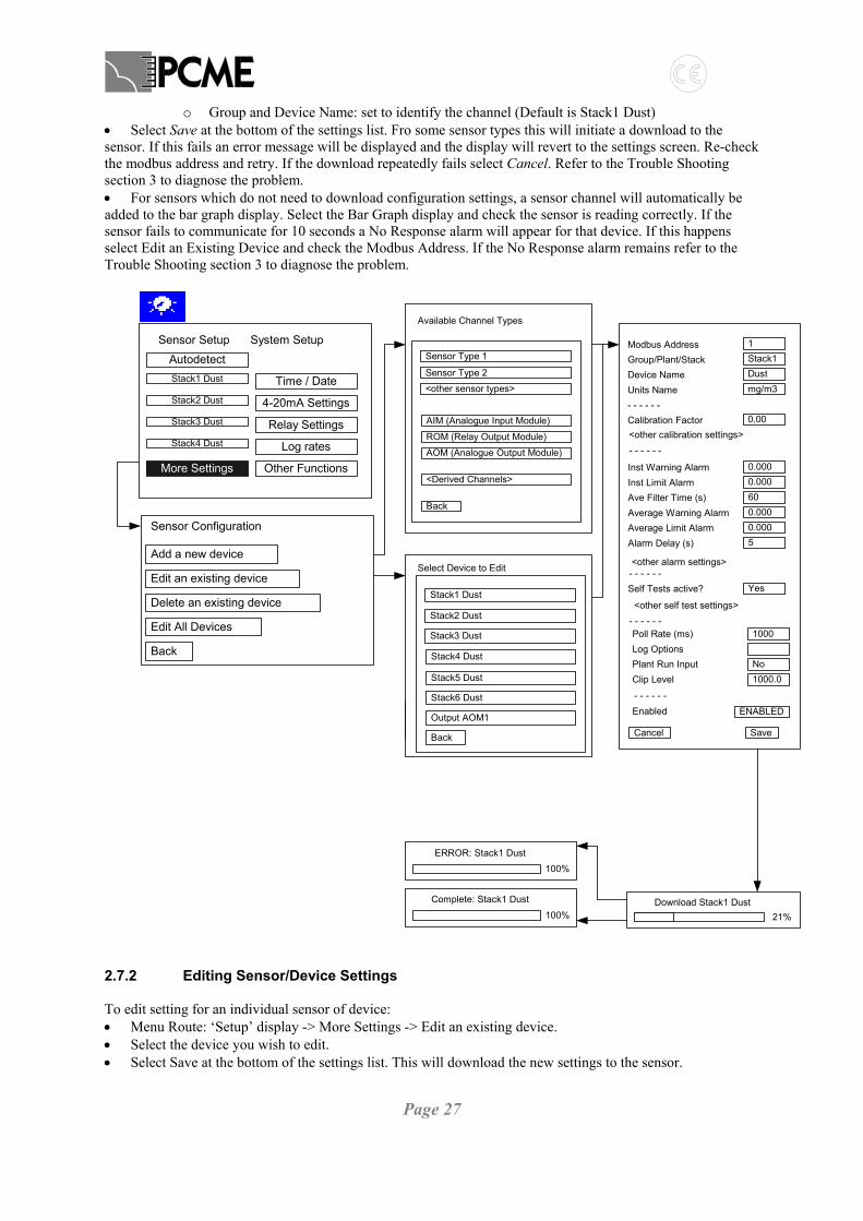
o Group and Device Name: set to identify the channel (Default is Stack1 Dust) • Select Save at the bottom of the settings list. Fro some sensor types this will initiate a download to the sensor. If this fails an error message will be displayed and the display will revert to the settings screen. Re-check the modbus address and retry. If the download repeatedly fails select Cancel. Refer to the Trouble Shooting section 3 to diagnose the problem. • For sensors which do not need to download configuration settings, a sensor channel will automatically be added to the bar graph display. Select the Bar Graph display and check the sensor is reading correctly. If the sensor fails to communicate for 10 seconds a No Response alarm will appear for that device. If this happens select Edit an Existing Device and check the Modbus Address. If the No Response alarm remains refer to the Trouble Shooting section 3 to diagnose the problem.
Download Stack1 Dust21%
Complete: Stack1 Dust
100%
AutodetectSensor Setup
Stack1 Dust Time / DateStack2 Dust 4-20mA SettingsStack3 Dust Relay SettingsStack4 Dust Log rates
More Settings Other Functions
System Setup 1Stack1Dustmg/m3
0.00
Modbus AddressGroup/Plant/StackDevice NameUnits Name- - - - - -Calibration Factor
Inst Warning AlarmInst Limit AlarmAve Filter Time (s)Average Warning AlarmAverage Limit AlarmAlarm Delay (s)
0.000
Self Tests active?
Poll Rate (ms)
Plant Run InputClip Level
Cancel
0.000600.0000.0005
Yes
1000
No1000.0
Save
Log Options
Enabled ENABLED
- - - - - -
- - - - - -
<other calibration settings>
<other alarm settings>
<other self test settings>- - - - - -
- - - - - -
Add a new device
Sensor Configuration
Edit an existing device
Delete an existing device
Edit All Devices
Back
Available Channel Types
Sensor Type 2
<other sensor types>
AIM (Analogue Input Module)
Back
<Derived Channels>
Sensor Type 1
ROM (Relay Output Module)
AOM (Analogue Output Module)
ERROR: Stack1 Dust100%
Select Device to Edit
Stack2 Dust
Stack3 Dust
Stack4 Dust
Back
Output AOM1
Stack1 Dust
Stack5 Dust
Stack6 Dust
ERROR: Stack1 Dust100%
2.7.2 Editing Sensor/Device Settings To edit setting for an individual sensor of device: • Menu Route: ‘Setup’ display -> More Settings -> Edit an existing device. • Select the device you wish to edit. • Select Save at the bottom of the settings list. This will download the new settings to the sensor.

Page 28
For a detailed explanation of the settings available for different sensor types refer to section 3. 2.7.3 Deleting Sensors/Devices To delete an individual sensor or device from the control unit: • Menu Route: ‘Setup’ display -> More Settings -> Delete an existing device. • Select the device you wish to delete. This will permanently remove all settings and logged data associated with this device. Entries in the Event log for this device will be marked as DELETED. 2.7.4 Editing Settings for all Sensors/Devices at once For large systems it may be more convenient to set all sensor settings to the same value at once e.g. to set all alarm levels to the same value. To do this: • Menu Route: ‘Setup’ display -> More Settings -> Edit all devices. • Select the parameter you wish to edit. The new setting will be applied to all sensors.
2.8 Other Functions Other functions and settings are available from the ‘Other Functions’ button. Refer to section 3.4.

Page 29
3 SENSOR SETTINGS Basic sensor settings are explained in the Basic Configuration section (see 2.2). This section explains the function of more advanced sensor settings. Menu route to edit sensor settings: Setup->More Settings->Edit an existing device.
3.1 Setting up Groups You need to set up Groups to determine how the Alarm Overview display and the display of Bar Graphs are arranged. The control unit is initially supplied with 4 groups named Stack1, Stack2, Stack3, and Stack4. All new devices added are initially all assigned to Stack1. • To assign a device to a different group:
o Choose Group/Plant/Stack from the device configuration settings. Then choose the desired group.
o Choose Select • To edit the group names: Choose each group, as above, but then choose Edit. This allows you to edit the group names. Once you have finished editing the group names, assign the required group as described above. • To add a new group: Choose Add a New Group to enter a new group name. Once the new group is added, assign the required group as described above. • To delete a group: Choose the group, as above, but then choose Delete. Once the group is deleted, assign the required group from the remaining list as described above.
S e le c t G ro u p
S ta ck1
S ta ck2
S ta ck3
S ta ck4
A d d a N e w G ro u p
S e le c t G ro u p
S ta ck1
S ta ck2
S ta ck3
S ta ck4
A d d a N e w G ro u p
E d it
D e le te
S e le c t
Page 30
3.2 Calibration Settings The Calibration Factor and Negative Offset allow the raw signal to be linearly calibrated:
Calibrated Reading = Calibration Factor x Raw Reading – Negative Offset
Set Use Multi Cal Factors? = Yes to use of the multiple calibration factors feature. See section 4.13 (Multi Cal Factors) for details. Calibration Range: this allows you to specify a range for which the calibration is valid. If the sensor reading goes above this range then logged data is marked as ‘invalid cal range’. This can be viewed using the reporting functions in Dust Reporter (set to 0 to disable this feature).
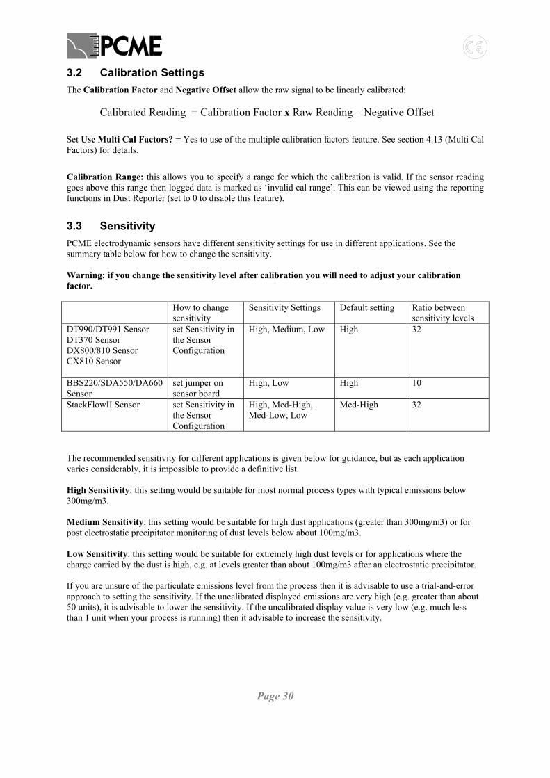
3.3 Sensitivity PCME electrodynamic sensors have different sensitivity settings for use in different applications. See the summary table below for how to change the sensitivity. Warning: if you change the sensitivity level after calibration you will need to adjust your calibration factor. How to change
sensitivity Sensitivity Settings Default setting Ratio between
sensitivity levels DT990/DT991 Sensor DT370 Sensor DX800/810 Sensor CX810 Sensor
set Sensitivity in the Sensor Configuration
High, Medium, Low High 32
BBS220/SDA550/DA660 Sensor
set jumper on sensor board
High, Low High 10
StackFlowII Sensor set Sensitivity in the Sensor Configuration
High, Med-High, Med-Low, Low
Med-High 32
The recommended sensitivity for different applications is given below for guidance, but as each application varies considerably, it is impossible to provide a definitive list. High Sensitivity: this setting would be suitable for most normal process types with typical emissions below 300mg/m3. Medium Sensitivity: this setting would be suitable for high dust applications (greater than 300mg/m3) or for post electrostatic precipitator monitoring of dust levels below about 100mg/m3. Low Sensitivity: this setting would be suitable for extremely high dust levels or for applications where the charge carried by the dust is high, e.g. at levels greater than about 100mg/m3 after an electrostatic precipitator. If you are unsure of the particulate emissions level from the process then it is advisable to use a trial-and-error approach to setting the sensitivity. If the uncalibrated displayed emissions are very high (e.g. greater than about 50 units), it is advisable to lower the sensitivity. If the uncalibrated display value is very low (e.g. much less than 1 unit when your process is running) then it advisable to increase the sensitivity.

Page 31
3.4 Alarm Settings The alarm settings are explained in the Basic Configuration section (see section 2.2)
3.5 Self Test Settings Use the Self Test Active? setting to enable/disable self tests. If self tests are enabled for your sensor the self-test results will appear on the QA (Quality Assurance / Self Tests) page. Other settings are provided to disable the alarms for individual self tests. These settings include: Zero/span alarms? Short Circuit alarm? Contam Ring alarm? Refer to section 6 (Self Checks) for detailed explanation of the use of Self Checks.
3.6 Poll Rate
This is the rate at which readings are taken from the sensor. With a small number of sensors (up to five) a faster poll rate may be set (e.g. 500ms). As the network becomes larger, the poll rate should be slowed (e.g. to 2000ms) to avoid the possibility of erroneous readings.
3.7 Log Options Select Log Options to display which channels are being logged for a given channel:
E n a b le L o g s
L o n g T e rm L o g
S h o r t T e rm L o g
P u lse L o g
B a c k
E v e n t L o g
To disable individual logging, uncheck each log option. This will provide more logging space for other channels. Note: some sensor /devices do not have a logging capability or allow restricted logging capability. If your sensor does not support a given log option then the check box for that log will be greyed out.
3.8 Plant Run Input This allows you to set up a digital input to monitor when your process is running /stopped. Enter the digital input number associated with this sensor (1-4: control unit input, 5-16: additional AIM inputs). See the Digital Inputs section (4.11) and Plant Run / Plant Stop section (4.12) for details. (Set to 0 to disable this feature).
3.9 Clip Level
This should be used to set a maximum emission level to avoid temporary spurious readings making logging averages meaningless. The default value is 1000 units.
3.10 Enabled Use to set channel in Maintenance Mode or Disabled Mode. See Maintenance Section (8) for more details.
Page 32
3.11 AIM Channels The AIM (Auxiliary Input Module) device is used to input analogue 4-20mA inputs and digital inputs into the controller. Once set up the analogue channels appear as normal sensor channels and can be used to generate alarms or act as inputs to derived channel calculations. AIM channels are added/edited in the same way as the sensor channels. Menu Route to Add an Analogue Input: Setup->More Settings->Add a new device->AIM Menu Route to Add Digital Inputs: Setup->More Settings->Add a new device->AIM Digital Many of the configuration options for AIM channels are common to the sensor channels (such as Group, Units, Log Options, Modbus address) and are described in the section above. Below is an explanation of the setup options specific to AIM channel. An AIM device has four analogue and four digital inputs. Each of the four analogue 4-20mA inputs can be used to create individual channels in the controller. For each analogue input you wish to measure, add an AIM device channel and select the analogue channel in the AIM Channel parameter. These are numbered from 1 to 4 and marked on the AIM board as AN1, AN2, AN3, and AN4. To calibrate the analogue 4-20mA inputs, set up the Zero Value and Span Value parameters. The Zero Value specifies the actual reading corresponding to 4mA input (usually set to 0); the Span Value specifies the actual reading corresponding to 20mA input. To set up a channel to record the digital inputs from the AIM, add an AIM Digital channel. The channel will then read in all four digital inputs. See the digital input section 4.11 for details of usage.
Page 33
4 OTHER FUNCTIONS This section describes additional functions available through the Other Functions menu.
AutodetectSensor Setup
----- Time / Date
----- 4-20mA Settings
----- Relay Settings
----- Log rates
More Settings Other Functions
System Setup
ASCII
19200
Sensor Comms mode
Baud Rate
Parity
Backlight off after
Software Version
Diagnostics?
Multi Cal facotrs
Digital Inputs
Odd
30
Back
mins
Comms Error Delay 10 seconds
7.01
EnglishLanguage
Latch Alarms?
FailSafe Relays?
Use Modem?
Advanced Functions
PC Communications
Maintenance Mode
Reset Functions
Set Password
Back
4.1 Language Menu Route: Setup -> Other Functions -> Language Set up your default language. A button is then available on the main Configure screen to toggle between the default language and English. If the default language is set to English then this button is not shown.
4.2 Latch Alarms, Fail Safe Relays Menu Route: Setup -> Other Functions-> Latch Alarms? Setup -> Other Functions-> Fail Safe Relays? These functions are described in section 2.5 (Relay Settings).
4.3 Use Modem Menu Route: Setup->Other Functions->PC Communications If a modem is used to link the control unit to the PC this should be ticked. Note: your modem should be connected to the Controller before activating this Modem setting. Then the controller will correctly initialise the modem to wait for requests from the PC.
Page 34
4.4 PC Communications Menu Route: Setup->Other Functions->PC Communications The PC Communications options allow setting of the serial communications settings for the secondary RS232/RS485 port for connection to a PC or PLC (the user port). Type: RS232 or RS485 Data Bits: 8 (fixed) Parity: None, Odd or Even Stop Bits: 1 or 2 Baud Rate: 4800 to 19200 Flow: None (fixed) Address: Default = 1 These parameters may be set to suit the device that is connected to the secondary port. The factory settings are RS232, No Parity, 1 Stop and 19200 Baud, which are the correct settings to work with the DustReporter software. The Address option allows you to daisy-chain several control units together using RS485. Each unit must be given a unique address. DustReporter will then automatically detect the different units connected to the PC.
4.5 Set Password This allows a user-defined password to be assigned to prevent unauthorised access to system critical functions. Menu route to change password: Setup->Other Functions->Set Password->Change Password The virtual keyboard will be displayed requesting that a new password be entered. Enter the new password. Re-enter the password to confirm the setting and return to the main menu. If password protection is not required enter a blank password. To secure the Controller: • Select the ‘Password Entry’ display • Select LOCK The ‘Configure’ display will be hidden from view until UNLOCK is selected and the password entered.
4.6 Reset Functions Menu Route: Setup->Other Functions-> Reset Functions. The controller has several ‘reset’ options within this menu: Master reset: Removes all installed devices, restores all factory settings and Clears All Logs Clear All Logs: Clears stored data from Long-Term, Short-Term and Pulse memories. There are also options to individually clear the Long Term, Short Term, Pulse and Alarm Log. Note: you cannot clear the log for a single sensor/channel individually. You must be absolutely sure that you wish to perform any of these reset functions as the data and/or settings will be lost.
Page 35
4.7 Maintenance Mode Menu Route: Setup -> Other Functions->Maintenance Mode. This function is explained in the Maintenance Section (8)
4.8 Sensor Comms mode, Baud Rate, Parity Menu Route: Setup -> Other Functions->Advanced Functions->Sensor Comms mode This allows the user to set the Sensor Network communication settings for the type of sensors in the system:
Mode Baud Rate Parity Standard Settings ASCII 19200 Odd Recommended for large systems (note 1)
RTU 19200 (note 2)
None (0Pty)
Notes 1) RTU is a faster communication protocol but is not available on the following devices:
BBS220, DA550, DA660, AIM. 2) If Baud rate is set slower then the sensor baud rate DIP switch must also be changed
4.9 Backlight off Menu Route: Setup -> Other Functions->Advanced Functions->Backlight off after To preserve the lifetime of the screen the backlight to the screen will turn off if the controller is not used for an extended period. The default turn off time is 30 mins but may be adjusted. Note: If the controller goes into alarm then the backlight will automatically come back on. Also the action of the alarm LED is unaffected by turning off the backlight.
4.10 Comms Error Delay Menu Route: Setup -> Other Functions->Advanced Functions->Comms Error Delay This setting defines the length of delay before a communication failure to a sensor causes a comms alarm. The default setting is 10 secs. If you find you are getting intermittent comms alarms then you can set this to a longer delay to ensure only genuine comms failures cause alarms. This is especially important if you are using Comms Alarms to trigger one of the alarm relays. Note: specific sensor alarms have their own alarm delay settings - see the sections on Sensor Configuration.
4.11 Digital Inputs Menu Route: Setup -> Other Functions->Advanced Functions->Digital Inputs. Digital inputs can entered into your control unit for a variety of purposes: To monitor Plant Run / Plant Stop conditions See Plant Run / Plant Stop feature section 4.12 To allow multiple Calibration factors to suit different process conditions
See Multiple Cal Factors section 4.13
To provide timing information (marker pulses) for analysis of bag cleaning pulses (using the Dust Reporter Predict software)
See Dust Reporter software manual for usage
Use the digital input screen to monitor the allocation and status of digital input configured into your controller. The Multicontroller has 4 digital input ports (the Interface Module has only 2 inputs ports). Other inputs ports can be assigned by add AIM devices into your modbus sensor network. Each AIM unit provides an additional 4 digital inputs.

Page 36
To set up AIM digital inputs: • Go to Configure->More Sensors->Add a new device • Select AIM digital channel • Select Save • This will automatically allocate 4 digital inputs on the Digital Inputs page. The diagram below shows the digital input page for a Multicontroller with one AIM unit. The controller inputs are number 1,2,3,4. The AIM inputs are numbered 5,6,7,8.
Input Status
BACK
1 Digital Inputs 1 OFF
2 Digital Inputs 2 ON
AMC1 MultiCalA OFF3 Digital Inputs 3 OFF
4 Digital Inputs 4 ON
5 AIM Digital 1
6 AIM Digital 2
7 AIM Digital 3
8 AIM Digital 4
OFF
OFF
OFF
OFF
4.12 Plant Run / Plant Stop Feature Digital inputs can be used to monitor the Plant Run / Plant Stop status of the process you are monitor. This is useful so: - you can generate reports including only time periods when the process is running. - you can disable spurious outputs and alarms during plant stop. • To set up the plant run / plant stop feature: each sensor can be set-up with an independent digital input.
Go to each sensor configuration setting in turn (Configure->Other Sensors->Edit an Existing Device) and set the Plant Run Input as follows:
0: plant run always on 1-4: digital inputs direct from the control unit 5-64: additional digital inputs from AIM devices (see Digital Input screen for allocation – section 4.11)
This allows for independent control of up to 64 sensors/processes. Of course multiple sensors can be linked to the same digital input if they are monitoring the same process.
• The digital input operates as follows: OFF: contact open: PLANT STOP ON: contact closed: PLANT RUN
• How is Plant Stop data displayed?
During Plant Stop: - all emission alarms are disabled - 4-20mA outputs from that channel are set to 0. - bar graph displays continue as normal but marked as STOP.

Page 37
- logging continues as normal but data is marked as ‘Plant Stop’. This can be used within the Dust Reporter software to control how Plant Stop data is displayed and whether to include Plant Stop data in average calculations.
4.13 Multi Cal Factors Menu Route: Setup -> Other Functions->Advanced Functions->Multi Cal Factors In some cases it is desirable to be able to apply different calibration factors to your sensors depending upon the process conditions pertaining (e.g. differing material batches). The controller allows four calibration factors to be applied to the sensors. The choice of calibration factor is made by means of the digital inputs 1 & 2. Example: A plant has 4 separate processes at different times, which require the following calibration factors. Process 1: 1.50 Process 2: 3.00 Process 3: 5.25 Process 4: 7.05 To set up your controller to use the different calibration factors: • In the Sensor Configuration Settings for the sensor:
o Set the Calibration Factor = 1.50 [for use with the first process] o Set Use Multi Cal Factors? = Yes
• Two digital inputs are used to provide 4 different input settings as shown in the table below.
• Calculate the ratio between the first calibration factor and the other calibration factors and enter them into
the System wide Settings: e.g. Cal Factor 1 = 3.00 / 1.50 = 2.00.
1.0000 (fixed)
Multi Calibration Factors
Cal Factor 0
Cal Factor 1
Cal Factor 2
Cal Factor 3
2.0000
3.5000
4.7000
Back
• Connect up the digital inputs inside the Controller so the choice of calibration factor can be made each time
the process changes. See electrical installation section for details. Note: if you only wish to use two cal factors (0 and 1), digital input 2 should be forced ON using a loopback wire.
Digital input 2 Digital input 1 Multi cal factor used ON ON Cal Factor 0 ON OFF Cal Factor 1 OFF ON Cal Factor 2 OFF OFF Cal Factor 3

Page 38
4.14 Diagnostics Mode This is used to aid diagnostics when setting up modbus communication between a SCADA/PLC and the control unit. Menu Route: Setup -> Other Functions->Advanced Functions->Diagnostics
4.15 Software Version Menu Route: Setup -> Other Functions->Advanced Functions->Software Version
Page 39
5 DERIVED CHANNELS As well as adding sensor channels to your controller, you can add additional derived channels, which allow you to make calculations by combining the data from the raw sensor channels. This is useful if you need to perform mass calculations or do oxygen or temperature compensation of your data. These channels are added/edited in the same way as the sensor channels. Menu Route to add: Setup->More Settings->Add a new device. Menu Route to edit: Setup->More Settings->Edit an existing device. The possible derived channels you can add are shown in the table below. Name Use Filter Provide additional filtering to a raw input channel Fixed Value Supply a constant known input value e.g. a fixed velocity for a mass calculation Mass Calculate mass emission = dust conc. x velocity x stack area Sum Sum the outputs from up to 4 individual sensor inputs Dust @ STP O2 Perform temperature, pressure, oxygen or moisture compensation on a dust channel Totaliser Create a running total of an input channel Averager Create a running average of an input channel Change Rate Calculates the rate of change of an input channel Max Min Calculates the Max or Min value on an input channel Some of the configuration options for the derived channels are common to the sensor channels (such as Group, Units, Log Options) and are described in the section above. Below is an explanation of the setup options specific to each of the derived channel types. Use of Groups: the channel Grouping feature in the controller is particularly useful for displaying derived channel information. If for example you have three stacks and you wish to measure the dust concentration and mass emission for each stack, then create 3 groups called Stack1, Stack2 and Stack3. You then need to set up three velocity channels and three mass channels (one in each group). You can then view all the information about a single stack together. Alarm Levels: it is possible to set up alarm levels for the mass channels independently of alarms for the Dust Concentration channel. 5.1.1 Filter The Filter channel is used to provide additional filtering to a raw input channel. Note filtering can also be applied directly to PCME Sensor channels (see configuring sensor channels). The choice of raw input channel is selected from the Input Channel parameter. The filter time is set in the Ave Filter Time parameter (default 60 secs) 5.1.2 Fixed Value To configure a fixed value channel, simply edit the Constant value to the known constant value. By default the Fixed Value channel is set up to provide a fixed velocity input (hence the Device Name is ‘Fixed Vel’ and the Units Name is ‘m/s’) but it may be used for other fixed value inputs such as ambient temperature or oxygen input. Note: Fixed value channels are not logged by default. 5.1.3 Mass The mass emissions from a stack is calculated by: Mass Emission (g/hr) = Dust Concentration (mg/m3) x Velocity (m/s) x Stack Area (m2) x Units Conversion

Page 40
The choice of Dust Concentration input is selected from the Dust Channel parameter. This can be from any PCME sensor direct into the controller or from an analogue input via an AIM device. The choice of Velocity input is selected from the Velocity Channel parameter. This can come either from a PCME velocity-measuring sensor, from an analogue input via an AIM device or simply a constant input from a Fixed Value channel. The Stack Area is set in the Area of Stack parameter. The Units Conversion is set up in the Unit multiplier parameter. By default this is set to 3.6. This is the correction conversion to obtain Mass emission in g/hr with the input units shown in the above formula. 5.1.4 Sum To log the combined output from several channels add a Sum channel. Set up Input Channels 1-4 as required depending on the number of channels you are combining. 5.1.5 Dust at STP O2 (Temperature, Pressure, Oxygen, Moisture Compensation) Use the Dust at STP O2 channel to normalise your dust measurement channels to STP (standard temperature and pressure). You can also normalise for changes in oxygen and moisture. By default, normalisation will be done to the following reference levels. These may be adjusted: Reference Level Parameter to adjust Temperature 0 ‘C = 273 K Temp Ref Level ‘C Pressure 1013 mbar = 101.3kPa = 760mm Hg Press Ref Level mbar Oxygen 11% Oxygen Ref Level % Moisture 0% (dry) The normalisation channel can be used in one of two ways: • Normalise using temperature and oxygen input channels:
o Feed the 4-20mA from your temperature or oxygen sensor into an AIM unit (Analogue Input Module – see section 3.11)
o Set Dust Channel = the unnormalised PCME dust reading channel o Set Temperature Channel = AIM temperature channel o Set Oxygen Channel = AIM oxygen channel
• Normalise using a fixed reading:
o Set Dust Channel = the unnormalised PCME dust reading channel o Set Fixed Temperature ‘C = the known temperature of your process o Set Fixed Pressure mbar = the known pressure of your process o Set Fixed Oxygen %= the known oxygen content of your process o Set Fixed Moisture % = the known moisture level of your process
Normalisation formula: Temperature: Dust @ STP (Nmg/m3) = Dust input (mg/m3) x (Temp input (°C) + 273) / 273 Pressure: Dust @ STP (Nmg/m3) = Dust input (mg/m3) x Pressure input (mbar) / 1013 Oxygen: Dust @ Ref O2 (mg/m3) = Dust input (mg/m3) x (20.9 - Oxygen Reference Level (%) ) / (20.9 - Oxygen input (%) ) Moisture: Dust (dry) = Dust (wet) x 100 / (100 - %Moisture)
Page 41
5.1.6 Totaliser The Totaliser channel is used to provide a running total of the input from another channel. The totaliser adds up all values from the input channel (at the poll rate of the input channel) and then divides the result by the Units Divider parameter. The choice of input channel is selected from the Input Channel parameter. The totaliser may be reset to zero by setting the Reset parameter to ‘Yes’ before selecting Save. 5.1.7 Averager The Averager channel is used to provide a running average of the input from another channel. This is built up for a given period set by the Ave Period setting. At the end of this period the average is reset and starts again. You can control the start of this averaging period using the Reset function and setting a Reset Delay. 5.1.8 Change Rate The Change Rate channel allows you to calculate the rate of change of an input channel. This may be used e.g. to calculate the feed rate from the output of a weighing scale. 5.1.9 Max Min The Max Min channel calculates the Maximum or Minimum value on an input channel. Use the Max/Min setting to choose whether to display the Maximum or Minimum value. Use the Period setting to choose the time period over which to calculate the Max or Min. You may reset this period at a specific time using the Reset and Reset Delay settings.
Page 42
6 QUALITY ASSURANCE AND SELF TESTS The QA (Quality Assurance) page provides a range of maintenance functions, summarised in the table below: FUNCTION PURPOSE Maintenance Mode (Start/Stop)
Place sensor in Maintenance Mode before cleaning or other maintenance of sensor
Calibration Perform calibration using results from Isokinetic sampling (see section 7) Comms Check Check communication between control unit and sensor Sensor Self Tests (Zero, Span, Contamination)
Run internal sensor self tests to check the validity of your measurement
The Specific operation of the Self Tests depend on the specific sensor type. Please refer to your user manual for details of the self test for your sensors.
Page 43
7 CALIBRATION
7.1 Introduction Calibration of each sensor is necessary on at least an annual basis and should be carried out either by PCME or an authorised PCME representative. The calibration is carried out with reference to an isokinetic sample (manual stack method). The isokinetic sample should be carried out to the relevant standards as defined by your local environmental authority or government agency. At its simplest level, the calibration procedure is carried out to calculate a Calibration Factor used to scale up the raw sensor readings into a true dust concentration value displayed directly in mg/m³. The use of a simple calibration factor is possible since the response of the instrument is directly proportional to the dust concentration over a predefined range.
7.2 Calculating the Calibration Factor The basic method to calculate a new Calibration Factor for your sensor uses the formula:
New Cal Factor = Current Cal Factor x ( Test Result / Sensor Average) The Test Result is the result obtained from a single sample of the stack. The Current Cal Factor is the calibration factor entered into the instrument at the time of the sampling. Note: The initial cal factor setting is 1.0 . The Sensor Average is the average of the readings displayed in your control unit using the current calibration factor. Example Sampling test result = 50mg/m3 Current Cal factor setting = 2.5 Instrument average = 20 units New Cal factor = 2.5 x (50 / 20) = 6.25
7.3 Calibration Procedure Each of the following steps must be carried out in the order given to guarantee a valid calibration: 1. Ensure that the sensors and controller are running properly. 2. Ensure the plant is running normally with representative conditions. 3. Carry out an isokinetic test. 4. Calculate the average sensor response displayed in your control unit (Sensor Average) 5. Record the sensor settings 6. Obtain the isokinetic sampling results (Test Result). 7. Calculate the New Cal Factor (See formula above). 8. Enter the new Cal Factor into the control unit. To do this go to the Configure Page. Select Sensor
Configuration. Select Edit an Existing Device. Select the required Device, and edit the Calibration Factor setting. You can also edit the Units displayed to mg/m3 if necessary.
7.4 Using the Calibration Tool This section explains the basic calibration tool. This should be used if :
• you are doing a simple calibration with a single sample. • you just wish to obtain sensor averages for your sample runs to send to PCME.

Page 44
More advanced calibration methods can be performed automatically using the Advanced Calibration Tool (see Main manual). Enter the Calibration Page for the required Device - Go to the Quality Assurance/Self Check page on your control unit and select the device you wish to calibrate.
Select Device
Stack1 Dust
Stack2 Dust
Stack3 Dust
Back
Quality Assurance / Self Tests
Stack1 DustCalibration
Device:i
Activate Zero Check PASS
Activate Span Check PASS
Comms Check PASS
Start Maint
Activate Short Circuit CheckContamination Ring
PASSPASS
- Select the Calibration button to enter the calibration page shown below.
CalculateSingle SampleCal Method
Start Time
Duration
Max Reading
Sensor Average
Test Result ExitCalc0.000
5.6315
7.3200
20 / 04 / 03 10 : 32
00 : 45
D M Y h m
Short Term
Note: Use the Left and Right cursor keys only to navigate through the Calibration page. The + and – cursor keys are used to edit the date and time. It is recommended that you download all existing data to DustReporter just before re-calibration. Then DustReporter will correctly report the time at which the calibration factor changed.

Page 45
8 MAINTENANCE
8.1 Overview The Control Unit records emissions and performs sensor checks on a continuous basis; it is, therefore, important to disable the sensor logging before carrying out any maintenance work which involves interfering with the sensor in the stack or disconnecting the sensor cable from the sensor. This is particularly important if the instrument is being used in an Environmental capacity, as any spurious recordings will appear in the Report.
8.2 Placing your sensors in Maintenance Mode When performing maintenance you can disable your sensors in several ways: 1. Power off the Control Unit: removes power from all sensors in the network. A ‘Power Interruption’ alarm will be recorded in the event log indicating the maintenance period. A gap will appear in all emission logs. 2. Disconnect the Sensor from the network: if the sensors are connected into the network using spurs it is possible to physically disconnect the sensor from the network without affecting polling to the other sensors. If you do this, a ‘No Response’ alarm will be generated in the Control Unit for that channel during the maintenance period. 3. Use the Maintenance Mode menu in the control unit: see below for details. Notes - Any sensors placed in Maintenance Mode will automatically return to normal Enabled operation after 8 hours. - It is possible to set up a relay to trigger when any sensor is placed in maintenance mode.

Page 46
AutodetectSensorSetup
----- Time / Date
----- 4-20mA Settings
----- Relay Settings
----- Log rates
More Settings Other Functions
System SetupEnglishLanguage
Latch Alarms?
FailSafe Relays?
Use Modem?
Advanced Functions
PC Communications
Maintenance Mode
Reset Functions
Set Password
Back
Start Maintenance (All Devices)
Maintenance Mode
Stop Maintenance (All Devices)
Individual Device Maintenance
Back BACK
EDIT
Stack 2 Dust MAINT
Stack 3 Dust MAINT
Stack 4 Dust ENABLED
Stack 1 Dust ENABLED
Stack 5 Dust DISABLED
To place your sensor into Maintenance Mode go to the configure page and select Maintenance Mode.
• To put all sensors in Maintenance Mode: select Start Maintained (All Devices) • To return all sensor to Enabled Mode: select Stop Maintenance (All Devices) • To place individual sensors in Maintenance Mode: select Individual Device Maintenance:
o Use the scroll bar to move the Cursor to the Required channel o Press Edit to change sensor to Maintenance Mode.
The maintenance mode setting toggles between 3 states explained below: ENABLED MAINTENANCE DISABLED Emission Alarms (Control Unit Relays + ROM devices)
active inactive inactive
Comms and Self Test Alarms
active active inactive
4-20mA Outputs (Control Unit Outputs + AOM devices)
active set to 0 set to 0
Bar Graph Displays active active ( labelled MAINT) set to 0 Logging active active (marked as
‘Maintenance’: data may be excluded from Dust Reporter reports)
inactive
Alarm Log - Maintenance Alarm -

Page 47
It is also possible to Start/Stop maintenance for a sensor from the QA page:
• Go to the QA page • Select the required sensor • Press the Start Maint or Stop Maint button

Page 48
9 MENU MAPS
9.1 Tool Bar
Stack1 Dust PulseDevice:
Set
Event Log Reset Latched Alarms
Stack1 Dust Warning AlarmStart 09:14:44 23/07/03 Duration 00:05:00
Overview
Stack3
OK
Stack4
OK
Stack1
OK
Stack2
OK
Stack1Dust
Stack2Dust
Stack3Dust
Stack4Dust
TEX
T
Stack1 Dust 0.45 mg/m3
Enable Logs
Long Term Log
Short Term Log
Pulse Log
Back
Event Log
Password Entry
To password protect your settings press LOCK
LOCK
To Set Password go to System Wide Settings
Quality Assurance / Self Tests
Stack1 Dust
Start Maint
Device:i
Contamination Ring 0
Activate Zero Check 0
Activate Span Check 9500
Comms Check
Calibration
Reset
Short CircuitCheck 10000Activate
Autodetect
Sensor Setup
----- Time / Date
----- 4-20mA Settings
----- Relay Settings
----- Log rates
More Settings Other Functions
System Setup
www.pcme.co.uk 7.01

Page 49
9.2 Basic Sensor Setup
Stack1 Dust 1 0.04 mg/m3Stack2 Dust 2 3.25 mg/m3
BAR
Scan adr 15 - found 3
Address 1 Device : DT990Address 2 Device: DT990Address 3 Device: AOM
Download Stack1 Dust21%
1.00000.00000.0000
600.00000.0000
5
Calibration FactorInstant Warning AlarmInstant Limit AlarmAveraging Time (sec)Average Warning AlarmAverage Limit AlarmAlarm Delay (sec)
Cancel Save
AutodetectSensor Setup
Stack1 Dust Time / Date
Stack2 Dust 4-20mA Settings
----- Relay Settings
----- Log rates
More Settings Other Functions
System Setup
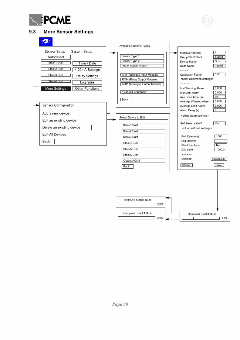
Page 50
9.3 More Sensor Settings
Download Stack1 Dust21%
Complete: Stack1 Dust
100%
AutodetectSensor Setup
Stack1 Dust Time / DateStack2 Dust 4-20mA SettingsStack3 Dust Relay SettingsStack4 Dust Log rates
More Settings Other Functions
System Setup 1Stack1Dustmg/m3
0.00
Modbus AddressGroup/Plant/StackDevice NameUnits Name- - - - - -Calibration Factor
Inst Warning AlarmInst Limit AlarmAve Filter Time (s)Average Warning AlarmAverage Limit AlarmAlarm Delay (s)
0.000
Self Tests active?
Poll Rate (ms)
Plant Run InputClip Level
Cancel
0.000600.0000.0005
Yes
1000
No1000.0
Save
Log Options
Enabled ENABLED
- - - - - -
- - - - - -
<other calibration settings>
<other alarm settings>
<other self test settings>- - - - - -
- - - - - -
Add a new device
Sensor Configuration
Edit an existing device
Delete an existing device
Edit All Devices
Back
Available Channel Types
Sensor Type 2
<other sensor types>
AIM (Analogue Input Module)
Back
<Derived Channels>
Sensor Type 1
ROM (Relay Output Module)
AOM (Analogue Output Module)
ERROR: Stack1 Dust
100%
Select Device to Edit
Stack2 Dust
Stack3 Dust
Stack4 Dust
Back
Output AOM1
Stack1 Dust
Stack5 Dust
Stack6 Dust
ERROR: Stack1 Dust
100%
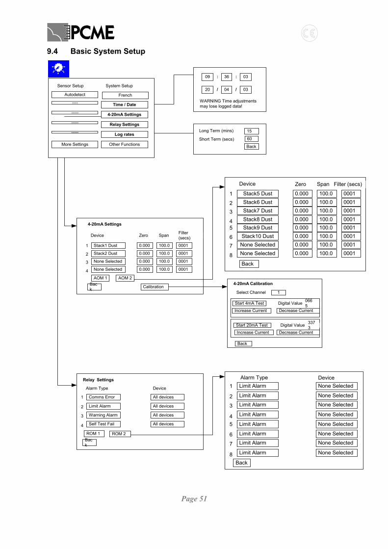
Page 51
9.4 Basic System Setup
WARNING Time adjustmentsmay lose logged data!
09 36 03
20 04 03
::
/ /
15Long Term (mins)
Short Term (secs)
Back
60
4-20mA Calibration
Select Channel
Back
1
Start 20mA Test
Increase Current Decrease Current
Digital Value 3373
Start 4mA Test
Increase Current Decrease Current
Digital Value 0665
Relay Settings
Alarm Type
1
2
3
Comms Error
Limit Alarm
Warning Alarm
Back
4 Self Test Fail
All devices
All devices
All devices
All devices
Device
ROM 1 ROM 2
Zero
4-20mA Settings
Device
1
2
3
Stack1 Dust
Stack2 Dust
None Selected
Back
Span Filter(secs)
4 None Selected
0.000 100.0 0001
0.000
0.000
0.000
100.0
100.0
100.0
0001
0001
0001
Calibration
AOM 1 AOM 2
Zero
1
23
Stack5 DustStack6 DustStack7 Dust
Back
Device Span Filter (secs)
4 Stack8 Dust
0.000 100.0 00010.0000.0000.000
100.0100.0100.0
000100010001
5
67
Stack9 DustStack10 Dust
None Selected
8 None Selected
0.000 100.0 00010.0000.0000.000
100.0100.0100.0
000100010001
Alarm Type1
2
3
Limit Alarm
Limit Alarm
Limit Alarm
Back
4 Limit Alarm
None Selected
None Selected
None Selected
None Selected
Device
5
6
7
Limit Alarm
Limit Alarm
Limit Alarm
8 Limit Alarm
None Selected
None Selected
None Selected
None Selected
Autodetect
Sensor Setup
---- Time / Date
----- 4-20mA Settings
----- Relay Settings
----- Log rates
More Settings Other Functions
System Setup
French
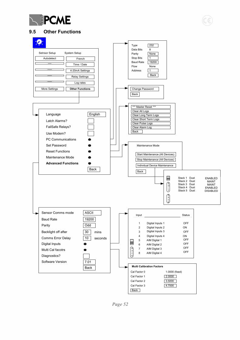
Page 52
9.5 Other Functions
EnglishLanguage
Latch Alarms?
FailSafe Relays?
Use Modem?
Advanced Functions
PC Communications
Maintenance Mode
Reset Functions
Set Password
Back
Type 232Data Bits 8Parity NoneStop Bits 1Baud Rate 19200Flow NoneAddress 1
Back
*** Master Reset ***
Back
Clear All LogsClear Long Term LogsClear Short Term LogsClear Pulse LogsClear Alarm Log
1.0000 (fixed)
Multi Calibration Factors
Cal Factor 0
Cal Factor 1
Cal Factor 2
Cal Factor 3
2.0000
3.5000
4.7000
Back
Start Maintenance (All Devices)
Maintenance Mode
Stop Maintenance (All Devices)
Individual Device Maintenance
Back
ASCII
19200
Sensor Comms mode
Baud Rate
Parity
Backlight off after
Software Version
Diagnostics?
Multi Cal facotrs
Digital Inputs
Odd
30
Back
mins
Comms Error Delay 10 seconds
7.01
Change Password
Back
BACK
EDIT
Stack 2 Dust MAINTStack 3 Dust MAINTStack 4 Dust ENABLED
Stack 1 Dust ENABLED
Stack 5 Dust DISABLED
Input Status
BACK
1 Digital Inputs 1 OFF2 Digital Inputs 2 ON
AMC1 OFF3 Digital Inputs 3
4 Digital Inputs 4 ON5 AIM Digital 16 AIM Digital 27 AIM Digital 38 AIM Digital 4
OFFOFFOFFOFF
Autodetect
Setnsor Setup
---- Time / Date
----- 4-20mA Settings
----- Relay Settings
----- Log rates
More Settings Other Functions
System Setup
French

Page 53
9.6 QA and Calibration
Start Time
Duration
Max Reading
Sensor Average
Test Result ExitCalc17.94
5.6315
7.3200
20 / 04 / 03 10 : 32
00 : 45
D M Y h m
ShortTerm
CancelBack
Sensor Average
Test Result
Current Cal
New Cal
Save
5.6315
17.94
1.0000
3.1856
Save New Calibration?
Yes No
Quality Assurance / Self Tests
Stack1 DustDevice:i
Activate Zero Check PASS/0
Activate Span Check PASS/10000
Contamination Ring PASS/5
Comms Check PASS
Calibration
Activate Short Circuit Check PASS/10000
Start Maint
Reset