convenience of open web flexibility of field … · flexibility of field trimming assurance of...
TRANSCRIPT

CONVENIENCE OF OPEN WEB
FLEXIBILITY OF FIELD TRIMMING
ASSURANCE OF INDIVIDUAL TESTING
The only all-wood, open-web floor truss.
For more information, visit www.openjoist.com

Open Joist
The Only All-Wood, Open-Web Floor Trusses
Table of Contents
• Truss Profiles . . . . . . . . . . . . . . . . . . . . . . . . . . . . . . . . . . . . . . . . . . . . 3
• Span Charts . . . . . . . . . . . . . . . . . . . . . . . . . . . . . . . . . . . . . . . . . . . . . 4
• Quality Control Testing and Warranty . . . . . . . . . . . . . . . . . . . . 6
• Handling and Safety . . . . . . . . . . . . . . . . . . . . . . . . . . . . . . . . . . . . . 7
• Framing Details . . . . . . . . . . . . . . . . . . . . . . . . . . . . . . . . . . . . . . . . . . 8
• Multifamily and Light Commercial Span Tables . . . . . . . . . . 11
• Fire Assembly – One-hour floor/ceiling . . . . . . . . . . . . . . . . . . 13
• Fire Assembly – Two-hour floor/ceiling . . . . . . . . . . . . . . . . . . 14
• Acoustical Performance . . . . . . . . . . . . . . . . . . . . . . . . . . . . . . . . . 16
• Chase Opening Chart . . . . . . . . . . . . . . . . . . . . . . . . . . . . . . . . . . . 17
• Connector Guide . . . . . . . . . . . . . . . . . . . . . . . . . . . . . . . . . . . . . . . 18
• Open Joist Specifications . . . . . . . . . . . . . . . . . . . . . . . . . . . . . . . 20
• Notes . . . . . . . . . . . . . . . . . . . . . . . . . . . . . . . . . . . . . . . . . . . . . . . . . . 22
Improving on a Solid ConceptOpen-web floor trusses have been meeting floor framing
challenges for years. They allow long spans and make it easy to
install electrical, plumbing and HVAC systems. Their strength
comes from the structural power of a triangle…a building
shape as old as civilization.
Open Joist Floor TrussesOpen Joist from Universal Forest Products is a revolutionary
all-wood, open-web, floor truss engineered with superior
strength and load-carrying capabilities.
Universal Forest Products Eastern Division, Inc. manufactures
the Open Joist product as a licensee of Distribution Open Joist
2000, Inc. All Open Joist product design and engineering cal-
culations are created by the licensor, Distribution Open Joist
2000, Inc.
Open Joist Provides You With: • Reduced shipping time
All of the benefits of engineered floor trusses, with quick
delivery from inventory.
• Wide nailing surface
Top and bottom flanges of 3x2 and 4x2 provide a wide
nailing surface for fasteners and adhesives, to help
ensure a quieter floor.
• Individually tested trusses
Open Joist is tested to more than twice its maximum
allowable load and is the only individually tested
floor truss product.
• Trimmable ends
Open Joist is available immediately from stock with
trimmable ends to fit exact framing dimensions. Up
to 5-1/2” can be trimmed off each end.
• Lifetime guarantee
Offers builders and homeowners peace of mind with
a lifetime guarantee.
• Code approvals
Open Joist is accredited by International Code Council Evaluation
Service Report Number ESR-1035 and is in compliance with the
following codes: 2006 International Building Code (IBC), 2006
International Residential Code (IRC), BOCA National Building
Code/1999 (BNBC), 1999 Standard Building Code (SBC) and the
1997 Uniform Building Code (UBC). Open Joist is accredited by
the city of Los Angeles (RR#25376 and RR#25584), New York
City (MEA#300-00-E), the city of Houston (#434B) and the
state of Florida (FL#5828). Code approval reports are available
at www.openjoist.com.
The pictures and diagrams in this brochure are for illustrative purposes only. Any construction or use of the product must be in accordance with local building codes. Universal Forest Products, Inc., its subsidiaries and affiliates (“Universal”) may provide a warranty with this product. Please ask for a copy when purchasing the product. Universal makes no warranty of any kind, express or implied, except as may be in its written warranty. All installation should be done by a licensed professional and appropriate safety measures should be taken when installing. Universal shall not be liable for any damages, including special and consequential damages that may result from the assembly or installing of this product. All engineered wood products are designed with specific limits to load capacity. Installer and/or end user should not exceed load capacities. Universal makes no warranty as to design of wall and roof loads, and all loads should be verified by a licensed professional.

Truss Profiles and Configurations
Mechanical Service Clearance
3
Standard OPEN JOIST Configurations
Joist Depth Joist Length Chord Size & Grade
9-1/4” 3’ through 16’ 3 x 2 - #2 SPF
9-1/4” 17’ through 20’ 4 x 2 - MSR 2100 SPF
11-7/8” 3’ through 17’ 3 x 2 - #2 SPF
11-7/8” 18’ through 19’ 4 x 2 - #2 SPF
11-7/8” 20’ through 23’ 4 x 2 - MSR 2100 SPF
14” 3’ through 18’ 3 x 2 - #2 SPF
14” 19’ through 21’ 4 x 2 - #2 SPF
14” 22’ through 25’ 4 x 2 - MSR 2100 SPF
16” 3’ through 17’ 3 x 2 - #2 SPF
16” 18’ through 22’ 4 x 2 - #2 SPF
16” 23’ through 26’ 4 x 2 - MSR 2100 SPF
16” 27’ through 30’ 4 x 2 - MSR 2400 SPF
4
Open Joist is accredited by International Code Council Evaluation Service Report Number
ESR-1035 and is in compliance with the following codes: 2006 International Building Code
(IBC), 2006 International Residential Code (IRC), BOCA National Building Code/1999 (BNBC),
1999 Standard Building Code (SBC) and the 1997 Uniform Building Code (UBC). Open
Joist is accredited by the city of Los Angeles (RR#25376 and RR#25584), New York City
(MEA#300-00-E), the city of Houston (#434B) and the state of Florida (FL#5828). Open Joist
is certified by Canadian report #CCMC 12118R and is in compliance with Part 4 and Part 9
of the National Building Code of Canada 1995, the Ontario Building Code 1995 and CAN/
CSA-086.1-M94 standards for limit state design and controlled vibration standards. Code
approval reports are available at www.openjoist.com.
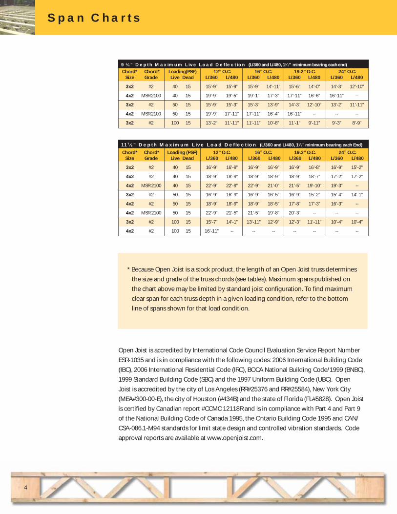
Span Charts
Chord* Chord* Loading(PSF) 12” O.C. 16” O.C. 19.2” O.C. 24” O.C. Size Grade Live Dead L/360 L/480 L/360 L/480 L/360 L/480 L/360 L/480
3x2 #2 40 15 15’-9” 15’-9” 15’-9” 14’-11” 15’-6” 14’-0” 14’-3” 12’-10”
4x2 MSR 2100 40 15 19’-9” 19’-5” 19’-1” 17’-3” 17’-11” 16’-6” 16’-11” --
3x2 #2 50 15 15’-9” 15’-3” 15’-3” 13’-9” 14’-3” 12’-10” 13’-2” 11’-11”
4x2 MSR 2100 50 15 19’-9” 17’-11” 17’-11” 16’-4” 16’-11” -- -- --
3x2 #2 100 15 13’-2” 11’-11” 11’-11” 10’-8” 11’-1” 9’-11” 9’-3” 8’-9”
117⁄8” Depth Maximum Live Load Deflection (L/360 and L/480, 11⁄2” minimum bearing each End)
* Because Open Joist is a stock product, the length of an Open Joist truss determines
the size and grade of the truss chords (see tables). Maximum spans published on
the chart above may be limited by standard joist configuration. To find maximum
clear span for each truss depth in a given loading condition, refer to the bottom
line of spans shown for that load condition.
91⁄4” Depth Maximum Live Load Deflection (L/360 and L/480, 11⁄2” minimum bearing each end)
Chord* Chord* Loading (PSF) 12” O.C. 16” O.C. 19.2” O.C. 24” O.C. Size Grade Live Dead L/360 L/480 L/360 L/480 L/360 L/480 L/360 L/480
3x2 #2 40 15 16’-9” 16’-9” 16’-9” 16’-9” 16’-9” 16’-8” 16’-9” 15’-2”
4x2 #2 40 15 18’-9” 18’-9” 18’-9” 18’-9” 18’-9” 18’-7” 17’-2” 17’-2”
4x2 MSR 2100 40 15 22’-9” 22’-9” 22’-9” 21’-0” 21’-5” 19’-10” 19’-3” --
3x2 #2 50 15 16’-9” 16’-9” 16’-9” 16’-5” 16’-9” 15’-2” 15’-4” 14’-1”
4x2 #2 50 15 18’-9” 18’-9” 18’-9” 18’-5” 17’-8” 17’-3” 16’-3” --
4x2 MSR 2100 50 15 22’-9” 21’-5” 21’-5” 19’-8” 20’-3” -- -- --
3x2 #2 100 15 15’-7” 14’-1” 13’-11” 12’-9” 12’-3” 11’-11” 10’-4” 10’-4”
4x2 #2 100 15 16’-11” -- -- -- -- -- -- --
Span Charts
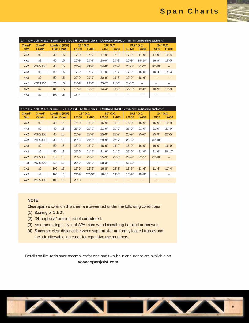
NOTE
Clear spans shown on this chart are presented under the following conditions:
(1) Bearing of 1-1/2”;
(2) “Strongback” bracing is not considered.
(3) Assumes a single layer of APA-rated wood sheathing is nailed or screwed.
(4) Spans are clear distance between supports for uniformly loaded trusses and
include allowable increases for repetitive use members.
5
Details on fire-resistance assemblies for one-and two-hour endurance are available on
www.openjoist.com
Span Charts
Chord* Chord* Loading (PSF) 12” O.C. 16” O.C. 19.2” O.C. 24” O.C. Size Grade Live Dead L/360 L/480 L/360 L/480 L/360 L/480 L/360 L/480
3x2 #2 40 15 17’-9” 17’-9” 17’-9” 17’-9” 17’-9” 17’-9” 17’-9” 16’-4”
4x2 #2 40 15 20’-9” 20’-9” 20’-9” 20’-9” 20’-9” 19’-10” 18’-9” 18’-5”
4x2 MSR 2100 40 15 24’-9” 24’-9” 24’-8” 22’-9” 23’-5” 21’-2” 20’-10” --
3x2 #2 50 15 17’-9” 17’-9” 17’-9” 17’-7” 17’-9” 16’-5” 16’-4” 15’-3”
4x2 #2 50 15 20’-9” 20’-9” 20’-9” 19’-8” 19’-9” 18’-6” -- --
4x2 MSR 2100 50 15 24’-9” 23’-2” 23’-2” 21’-0” 21’-10” -- -- --
3x2 #2 100 15 16’-9” 15’-2” 14’-4” 13’-8” 12’-10” 12’-8” 10’-9” 10’-9”
4x2 #2 100 15 18’-4” -- -- -- -- -- -- --
16” Depth Maximum Live Load Deflection (L/360 and L/480, 11⁄2” minimum bearing each end)
Chord* Chord* Loading (PSF) 12” O.C. 16” O.C. 19.2” O.C. 24” O.C. Size Grade Live Dead L/360 L/480 L/360 L/480 L/360 L/480 L/360 L/480
3x2 #2 40 15 16’-9” 16’-9” 16’-9” 16’-9” 16’-9” 16’-9” 16’-9” 16’-9”
4x2 #2 40 15 21’-9” 21’-9” 21’-9” 21’-9” 21’-9” 21’-9” 21’-9” 21’-9”
4x2 MSR 2100 40 15 25’-9” 25’-9” 25’-9” 25’-9” 25’-9” 25’-6” 25’-9” 22’-5”
4x2 MSR 2400 40 15 29’-9” 29’-8” 29’-9” 27’-7” 28’-5” -- 26’-10” --
3x2 #2 50 15 16’-9” 16’-9” 16’-9” 16’-9” 16’-9” 16’-9” 16’-9” 16’-9”
4x2 #2 50 15 21’-9” 21’-9” 21’-9” 21’-9” 21’-9” 21’-9” 21’-9” 20’-10”
4x2 MSR 2100 50 15 25’-9” 25’-9” 25’-9” 25’-0” 25’-9” 22’-5” 23’-10” --
4x2 MSR 2400 50 15 29’-9” 28’-2” 28’-3” -- 26’-10” -- -- --
3x2 #2 100 15 16’-9” 16’-9” 16’-8” 16’-8” 13’-6” 13’-6” 11’-4” 11’-4”
4x2 #2 100 15 21’-9” 20’-10” 19’-1” 19’-0” 16’-9” 15’-9” -- --
4x2 MSR 2100 100 15 23’-3” -- -- -- -- -- -- --
14” Depth Maximum Live Load Deflection (L/360 and L/480, 11⁄2” minimum bearing each end)
Span Charts

Quality Control Testing and Warranty
6
Individually Tested
Open Joist is the only floor framing
product utilizing continual testing.
A hydraulically powered test press
applies a load to the test truss
equivalent to 2.1 times the maxi-
mum allowable load. If there are
any defects within the truss, it will
break or deform on the test rack.
This process assures that you
received the best quality product
at your job site.
OPEN JOISTTTMM
WARRANTYUniversal Forest Products Eastern Division, Inc. and its affiliates, manufacturer of OPEN JOIST products ("the Products"),
warrants that its Products are certified by Warnock Hersey to ensure their compliance with the legal standards then applicable
to the Products, and that each of its Products listed on its load table is tested at twice its maximum weight capacity as described
on such load table, and that it shall be free of defects of workmanship and material.
In the unlikely event that a manufacturing defect arises, since each of the Products listed on the manufacturer's load table has
been tested individually, the Company shall replace such defective Product, at its cost and expense, provided that the
purchaser shall have given to the manufacturer notice of a defect in the Product within 30 days of the purchaser being notified
or from when the purchaser first became aware of such defective Product. Such replacement is the purchaser's sole and exclusiv e
remedy for breach of warranty. This warranty shall be in force for the lifetime of the structure of the end user.
LIMITATIONS AND EXCLUSIONS
THE ABOVE WARRANTY SHALL NOT EXTEND TO PRODUCTS MISUSED, NEGLECTED, SUBJECTED TO
ABNORMAL STORAGE, USE OR EXPOSURE OR WHICH HAVE BEEN ALTERED IN ANY MANNER OR NOT
MAINTAINED IN ACCORDANCE WITH PUBLISHED INSTRUCTIONS. THE PRODUCTS MUST BE HANDLED AND
INSTALLED IN ACCORDANCE WITH THE MANUFACTURER'S PUBLISHED INSTRUCTIONS.
THERE ARE NO WARRANTIES WHICH EXTEND BEYOND THE DESCRIPTION ON THE FACE HEREOF. THE
MANUFACTURER DOES NOT GRANT ANY WARRANTY, EITHER EXPRESS OR IMPLIED, LEGAL OR
CONVENTIONAL, AND DISCLAIMS ALL IMPLIED WARRANTIES OF MERCHANTABILITY AND FITNESS FOR
PARTICULAR PURPOSE. THE MANUFACTURER SHALL NOT BE LIABLE FOR ANY INDIRECT, SPECIAL,
INCIDENTAL OR CONSEQUENTIAL DAMAGES, EVEN IF THE MANUFACTURER HAS BEEN ADVISED OF THE
POSSIBILITY OF SUCH DAMAGES.
Universal Forest Products Eastern Division, Inc.
3560_8/07
Lifetime Warranty
Because Open Joist trusses are
individually tested, they offer
permanent quality assurance
against floor system failure.
Property owners can rest assured
that their structure built with
Open Joist comes with a lifetime
warranty.
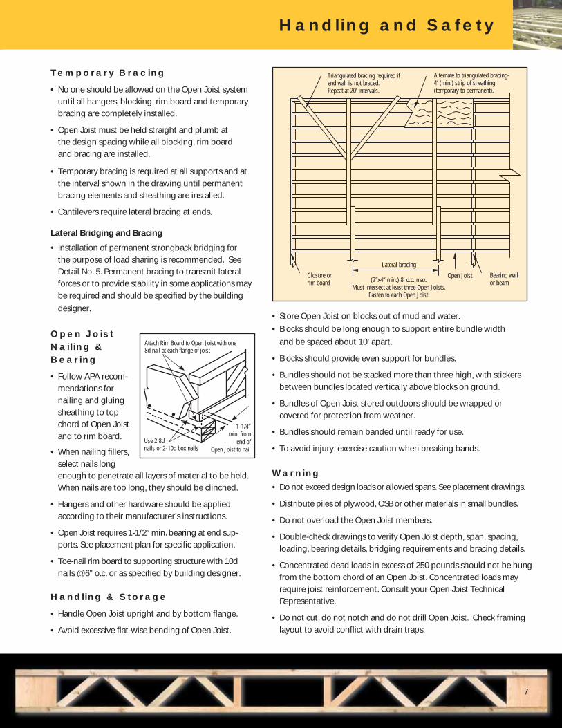
Temporary Bracing
• No one should be allowed on the Open Joist system
until all hangers, blocking, rim board and temporary
bracing are completely installed.
• Open Joist must be held straight and plumb at
the design spacing while all blocking, rim board
and bracing are installed.
• Temporary bracing is required at all supports and at
the interval shown in the drawing until permanent
bracing elements and sheathing are installed.
• Cantilevers require lateral bracing at ends.
Lateral Bridging and Bracing
• Installation of permanent strongback bridging for
the purpose of load sharing is recommended. See
Detail No. 5. Permanent bracing to transmit lateral
forces or to provide stability in some applications may
be required and should be specified by the building
designer.
Open Joist Nailing & Bearing
• Follow APA recom-
mendations for
nailing and gluing
sheathing to top
chord of Open Joist
and to rim board.
• When nailing fillers,
select nails long
enough to penetrate all layers of material to be held.
When nails are too long, they should be clinched.
• Hangers and other hardware should be applied
according to their manufacturer’s instructions.
• Open Joist requires 1-1/2” min. bearing at end sup-
ports. See placement plan for specific application.
• Toe-nail rim board to supporting structure with 10d
nails @ 6” o.c. or as specified by building designer.
Handling & Storage
• Handle Open Joist upright and by bottom flange.
• Avoid excessive flat-wise bending of Open Joist.
Handling and Safety
7
Closure or rim board
Lateral bracing
(2”x4” min.) 8’ o.c. max.Must intersect at least three Open Joists.
Fasten to each Open Joist.
Open Joist Bearing wall or beam
Triangulated bracing required if end wall is not braced.Repeat at 20’ intervals.
Alternate to triangulated bracing- 4’ (min.) strip of sheathing(temporary to permanent).
• Store Open Joist on blocks out of mud and water.
• Blocks should be long enough to support entire bundle width
and be spaced about 10’ apart.
• Blocks should provide even support for bundles.
• Bundles should not be stacked more than three high, with stickers
between bundles located vertically above blocks on ground.
• Bundles of Open Joist stored outdoors should be wrapped or
covered for protection from weather.
• Bundles should remain banded until ready for use.
• To avoid injury, exercise caution when breaking bands.
Warning• Do not exceed design loads or allowed spans. See placement drawings.
• Distribute piles of plywood, OSB or other materials in small bundles.
• Do not overload the Open Joist members.
• Double-check drawings to verify Open Joist depth, span, spacing,
loading, bearing details, bridging requirements and bracing details.
• Concentrated dead loads in excess of 250 pounds should not be hung
from the bottom chord of an Open Joist. Concentrated loads may
require joist reinforcement. Consult your Open Joist Technical
Representative.
• Do not cut, do not notch and do not drill Open Joist. Check framing
layout to avoid conflict with drain traps.
Attach Rim Board to Open Joist with one 8d nail at each flange of joist
Use 2 8d nails or 2-10d box nails
1-1/4” min. from
end of Open Joist to nail

Framing Detail Suggestions
8
Truss End Trim
End-to-End on Interior Bearing
Perpendicular Joist on End Bearing Wall
Overlapping on Interior Bearing
End-to-End on Interior Bearing Joist to Wood Beam with Appropriate Hanger
De
tail
No
. 1
De
tail
No
. 2
De
tail
No
. 3
a
De
tail
No
. 3
De
tail
No
. 3
b
De
tail
No
. 4
5-1/2” (max.) trim
1-3/4” (min.)remaining
Sub-floor - (min. 5/8”)
Bearing wall
Min. 1-3/4”
Min. 1-3/4”Min. 1-1/2” bearing
Bearing wall or beam (3” min.)
Bearing wall or beam (3” min.)
1-1/2” min. endblock on bearing
1-1/2” min. endblock on bearing
Min. 1-1/2” bearing
Int. bearing wall
Continuous solid bridging - only under bearing wall2x4 for 9-1/4”, 11-7/8”2x6 for 14”, 16”
Min. 1-3/4”
Bearing wall or beam (3” Min.)
Engineered or conventionalwood beam
Hanger
Plan view
Framing Detail Suggestions
Recommended Continuous Strongback Bridging
NOTE: Not required
De
tail
No
. 5
Continuous strongback bridging recommended every 7’-0” nailed as indicated with (2) 3” nails.
Framer is advised to install and nail all strongbacks before installation of the sub floor.
9 1/4” Joists - 2x4 strongback11 7/8” Joists - 2x4 strongback14” Joists - 2x6 strongback16” Joists - 2x6 strongback
Parallel Joist on End Bearing Wall
De
tail
No
. 6
Bearing wall
Sub floor(min. 5/8”)
Recommended continuousstrongback bridging
Parallel Rim on End Bearing Wall
De
tail
No
. 6
a
Blocking
Bearing wall
Sub floor(min. 5/8”)
Recommended continuousstrongback bridging
Rim material. (A minimum 1” board is recommended. Final size shall be per the construction plans. For closure boards other sizes and details may be used).
Rim material. (If the rim is structural, a min. 1” board is recommended. For closure boards other sizes and details may be used).
Rim material. (If the rim is structural, a min. 1” board is recommended. For closure boards other sizes and details may be used).

Framing Detail Suggestions
Cantilever Supporting Load Bearing Wall
Stair Header
Short Cantilever without Reinforcement Supporting Load Bearing Wall
Reinforcement for Point Load
Cantilevered Balcony or PlatformSolid Lumber Cantilever Perpendicular to Open Joist
Joist to Steel Beam with Appropriate Hanger Typical Fire Separation Wall
9
De
tail
No
. 8
De
tail
No
. 8
aD
eta
il N
o.
11
De
tail
No
. 1
0D
eta
il N
o.
12
De
tail
No
. 1
3
De
tail
No
. 1
5
De
tail
No
. 1
6
OSB or Plywood Gusset Glued and Nailed to Top and Bottom Chords
With Nails at Specified Spacing
Load Bearing Wall
Sill PlateCantilever
Exterior Bearing Wall or Beam
Load Bearing Wall
Varies According to Framing Members and Loads
Masonry FoundationBearing Wall
Sill Plate
Gusset - (min. 7/16” OSB) glued and nailed to top and bottom chords with 3” nails at specified spacing
Top mount hanger
Engineered or conventional wood beam attached with top mount hanger
OSB or plywood gusset glued and nailed to top and bottom chords
with nails at specified spacing
Point load
Bearing wall or beam
Optional flush framing
Dimensional lumber fixed to webs with 16d x 3” long common wirenails spaced 4” o.c.
Wood support
Dimensionallumber
Support nailed to joist
NOTE: Cantilevered dimensional lumber must be engineered for load and deflection per applicable code.
Top mount hanger
Wood support bolted to beam
Optional wood support bolted to beam
Steel beam
Continuous solid bridging2x4 for 9-1/4”, 11-7/8”2x6 for 14”, 16”
Bearing wallMasonry wall
Air space or fire-rated drywall according to local code
stringer
E* Engineering required. Engineered drawings will specify gussets and fastening.
Framing Detail Suggestions
E* E*
E* E*
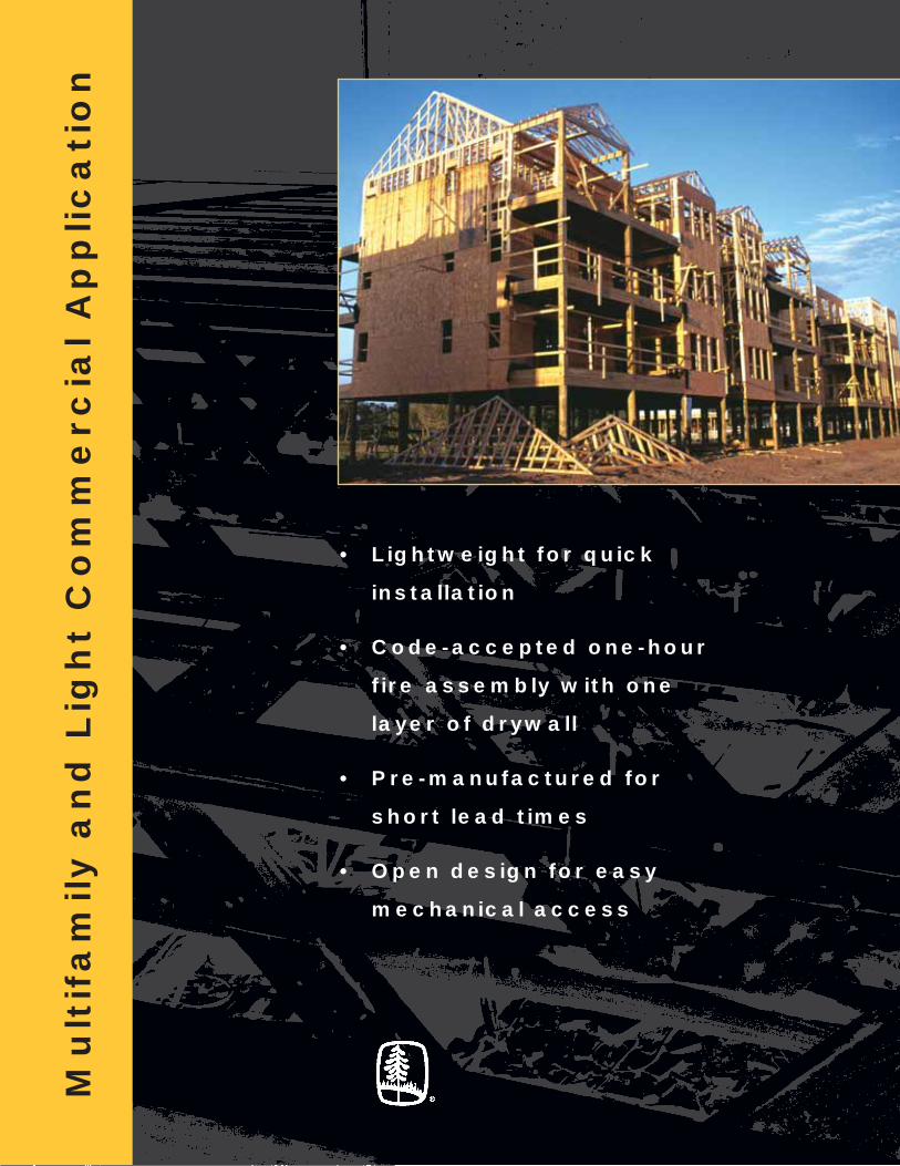
Mu
ltif
am
ily a
nd
Lig
ht
Co
mm
erc
ial A
pp
lic
ati
on
• Lightweight for quick
installation
• Code-accepted one-hour
fire assembly with one
layer of drywall
• Pre-manufactured for
short lead times
• Open design for easy
mechanical access

25 psf Dead Load Clear Span Floor Table
You will appreciate the perfor-
mance from OPEN JOIST when
using a strongback to control
vibration and increase stiffness.
Continuous strongback bridging
(kiln-dried) every 7’-0” nailed
to bottom chord and webs
is recommended. For greater
effectiveness, nail all strong-
backs before the installing the
subfloor.
* Because Open Joist is a “stock”
product, the length of an Open Joist
truss determines the size and grade
of the truss chords (see tables).
Maximum spans published on the
chart (right) may be limited by
standard joist configuration. To find
maximum clear span for each truss
depth in a given loading condition,
refer to the bottom line of spans
shown for that load condition.
NOTE
Clear spans shown on this
chart are presented under
the following conditions:
(1) Bearing of 1-1/2”.
(2) “Strongback” bracing
is not considered.
(3) Assumes a single layer of
APA-rated wood sheathing
is nailed or screwed.
(4) Spans are clear distance
between supports for
uniformly loaded trusses
and include allowable
increases for repetitive
use members.
Chord* Chord* Loading(PSF) 12” O.C. 16” O.C. 19.2” O.C. 24” O.C. Size Grade Live Dead L/360 L/480 L/360 L/480 L/360 L/480 L/360 L/480
3x2 #2 40 25 15’-9” 15’-9” 15’-9” 14’-11” 15’-6” 14’-0” 14’-2” 12’-10”
4x2 MSR 2100 40 25 19’-9” 19’-5” 18’-9” 17’-3” 17’-11” 16’-6” 15’-3” --
3x2 #2 50 25 15’-9” 15’-3” 15’-3” 13’-9” 14’-3” 12’-10” 13’-0” 11’-11”
4x2 MSR 2100 50 25 19’-9” 17’-11” 17’-11” 16’-4” 16’-6” -- -- --
3x2 #2 100 25 13’-2” 11’-11” 11’-11” 10’-8” 10’-5” 9’-11” 8’-6” 8’-6”
117⁄8” Depth Maximum Live Load Deflection (L/480, 11⁄2” minimum bearing each end)
Chord* Chord* Loading (PSF) 12” O.C. 16” O.C. 19.2” O.C. 24” O.C. Size Grade Live Dead L/360 L/480 L/360 L/480 L/360 L/480 L/360 L/480
3x2 #2 40 25 16’-9” 16’-9” 16’-9” 16’-9” 16’-9” 16’-8” 16’-9” 15’-2”
4x2 #2 40 25 18’-9” 18’-9” 18’-9” 18’-9” 18’-9” 18’-1” 17’-7” --
4x2 MSR 2100 40 25 22’-9” 22’-9” 22’-0” 21’-1” 20’-10” 20’-0” -- --
3x2 #2 50 25 16’-9” 16’-9” 16’-9” 16’-5” 16’-1” 15’-2” 14’-1” 14’-1”
4x2 #2 50 25 18’-9” 18’-9” 18’-5” 18’-5” 17’-0” 17’-0” -- --
4x2 MSR 2100 50 25 22’-9” 21’-6” 21’-4” 19’-9” 19’-3” -- -- --
3x2 #2 100 25 15’-7” 14’-1” 13’-1” 12’-9” 11’-7” 11’-7” 9’-8” 9’-8”
91⁄4” Depth Maximum Live Load Deflection (L/480, 11⁄2” minimum bearing each end)
11

12
25 psf Dead Load Clear Span Floor Table
Chord* Chord* Loading(PSF) 12” O.C. 16” O.C. 19.2” O.C. 24” O.C. Size Grade Live Dead L/360 L/480 L/360 L/480 L/360 L/480 L/360 L/480
3x2 #2 40 25 17’-9” 17’-9” 17’-9” 17’-9” 17’-9” 17’-9” 16’-4” 16’-4”
4x2 #2 40 25 20’-9” 20’-9” 20’-9” 20’-9” 19’-9” 19’-9” 17’-4” 17’-4”
4x2 MSR 2100 40 25 24’-9” 24’-9” 24’-8” 22’-9” 23’-5” 21’-3” 21’-4” --
3x2 #2 50 25 17’-9” 17’-9” 17’-9” 17’-7” 17’-1” 16’-5” 15’-2” 15’-2”
4x2 #2 50 25 20’-9” 20’-9” 20’-4” 19’-8” 18’-2” 18’-2” -- --
4x2 MSR 2100 50 25 24’-9” 23’-2” 22’-10” 21’-0” 20’-1” -- -- --
3x2 #2 100 25 16’-8” 15’-3” 14’-8” 13’-9” 12’-7” 12’-7” 10’-8” 10’-8”
4x2 #2 100 25 17’-9” -- -- -- -- -- -- --
16” Depth Maximum Live Load Deflection (L/480, 11⁄2” minimum bearing each end)
Chord* Chord* Loading(PSF) 12” O.C. 16” O.C. 19.2” O.C. 24” O.C. Size Grade Live Dead L/360 L/480 L/360 L/480 L/360 L/480 L/360 L/480
3x2 #2 40 25 16’-9” 16’-9” 16’-9” 16’-9” 16’-9” 16’-9” 16’-9” 16’-9”
4x2 #2 40 25 21’-9” 21’-9” 21’-9” 21’-9” 21’-9” 21’-9” 21’-9” 21’-9”
4x2 MSR 2100 40 25 25’-9” 25’-9” 25’-9” 25’-9” 25’-9” 25’-6” 23’-10” --
4x2 MSR 2400 40 25 29’-9” 29’-8” 29’-9” 27’-7” 28’-5” 26’-0” 23’-10” --
3x2 #2 50 25 16’-9” 16’-9” 16’-9” 16’-9” 16’-9” 16’-9” 16’-9” 16’-9”
4x2 #2 50 25 21’-9” 21’-9” 21’-9” 21’-9” 21’-9” 21’-9” 21’-6” 21’-0”
4x2 MSR 2100 50 25 25’-9” 25’-9” 25’-9” 25’-0” 24’-10” 22’-5” -- --
4x2 MSR 2400 50 25 29’-9” 28’-2” 28’-2” -- -- -- -- --
3x2 #2 100 25 16’-9” 16’-9” 14’-8” 14’-8” 12’-7” 12’-7” 10’-8” 10’-8”
4x2 #2 100 25 21’-9” 20’-0” 20’-0” 19’-0” -- -- -- --
4x2 MSR 2100 100 25 23’-5” -- -- -- -- -- -- --
14” Depth Maximum Live Load Deflection (L/480, 11⁄2” minimum bearing each end)
* Because Open Joist is a stock
product, the length of an Open Joist
truss determines the size and grade
of the truss chords (see tables below).
Maximum spans published on the
chart (below left) may be limited by
standard joist configuration. To find
maximum clear span for each truss
depth in a given loading condition,
refer to the bottom line of spans
shown for that load condition.
NOTE
Clear spans shown on this
chart are presented under
the following conditions:
(1) Bearing of 1-1/2”.
(2) “Strongback” bracing
is not considered.
(3) Assumes a single layer of
APA-rated wood sheathing
is nailed or screwed.
(4) Spans are clear distance
between supports for
uniformly loaded trusses
and include allowable
increases for repetitive
use members.

1. Topping: Topping is optional. Can be lightweight or
proprietary topping.
2. Subflooring: 5/8” tongue-and-groove plywood or
oriented strandboard (OSB).
3. Structural members: Open Joist floor trusses, from
a minimum depth of 9-1/4” to a maximum depth of 16”,
installed up to 24” on-center, maximum load design
according to manufacturer L/480 load tables, with struc-
tural-graded 3x2 or 4x2 chords per NLGA grading
rules for Canadian Lumber or graded by an inspection
bureau or agency approved by the United States Depart-
ment of Commerce Board of Review of the American
Lumber Standards Committee with chord sizes of 3x2 or
4x2. Structural members should bear the WHI certification
mark.
4. Bridging: Continuous 2x4 lumber nailed to the bottom
chord and the sides of the diagonals with 3” long nails.
5. Resilient channel: (Optional: For acoustic performance
only.) Rigid steel furring channels (inverted hat-type)
spaced 16” on-center and attached to the bottom chord
by means of two Type W screws. Channels overlap on
10” at the end and are attached to each other by a 1-1/4”
Type S screw.
6. Gypsum board: One layer of 5/8” Type X. Long edges
located between joists perpendicular to the resilient
channels. Short edges are staggered by 4 feet. Sheets are
fastened to the resilient channels by means of 1-1/2” Type
S screws located 1-1/2” away from the edge and 3” from the
long edges. Screws are spaced 6” on-center. Joints are
taped and finished with two layers of compound.
7. Insulation: Insulation material is optional for acoustic
and/or thermal protection.
Results obtained have been performed by Inchcape Testing Services NA Ltd-Warnock Hersey and are in accordance with
ASTM E –119, CAN.ULC S-101 and UL-263.
21
4 5 6
3
7
13
Fire Assembly
One-Hour Floor / Ceiling System L/480 (#OJ/FCA 60-02)

21
4 5
3
76
14
Results obtained have been performed by Intertek Testing Services NA, Inc., and are in accordance with
ASTM E –119, CAN.ULC S-101 and UL-263.
Fire Assembly Two-Hour Floor / Ceiling System L/480 (#OJ/FCA 120-01)
1. Topping: Topping is optional. Can be lightweight
or proprietary topping.
2. Subflooring: Minimum 5/8” tongue-and-groove
sheathing.
3. Structural members: Open Joist, minimum depth
9-1/4”, installed up to 24” on-center, with structural-graded
3x2 or 4x2 chords per NLGA grading rules for Canadian
Lumber or graded by an inspection bureau of agency
approved by the United States Department of Commerce
Board of Review of the American Lumber Standards
Committee with chord sizes of 3x2 and 4x2. Open Joist
should bear the WHI certification mark.
4. Bridging: Continuous 2x4 lumber nailed to the bottom
chord and the sides of the diagonals with 2” long nails.
The ceiling membrane shall consist of three layers of
15.9-mm (5/8”) proprietary Type C gypsum board. Each
sheet will be not less than 1.22-m (4’) wide. Acceptable
products include, but are not limited to, Lafarge North
America Firecheck C gypsum board National Gypsum Gold
Bond Fireshield C gypsum board, and Georgia Pacific (GP)
Gypsum ToughRock Fire Guard C gypsum board.
5. Resilient channel: Rigid steel furring channels (inverted
hat-type) approximately 19-mm (3/4” deep) spaced not
more than 406-mm (16”) o.c. These channels shall be
oriented perpendicular to the joists and attached to each
truss using 70-mm (1-1/2”) Type S or W screws.
If Open Joist members are installed at 16” o.c. or less,this
resilient channel is optional.

15
Fire Assembly continued
Open Joist’s unique
finger-joinery construction
is held together with
a structural adhesive that is resistant to water, heat and fire.
Open Joist uses a phenol resorcinol adhesive developed by
Hexion Specialty Chemicals, Inc. to ensure superior strength
and performance.
HexiTherm Adhesives are a family of products specifically
developed to provide superior heat performance for today’s
engineered wood applications. Utilizing state-of-the-art
thermosetting and emulsion technologies, HexiTherm products
are thermally stable under the most rigorous conditions.
HexiTherm Adhesives meet or exceed the highest heat-and fire-
resistance standards in the wood products industry. They are
certified, for example, by the American Lumber Standard
Committee (ALSC) as Heat Resistant Adhesives (HRAs) for finger-
jointed stud applications. They have also been tested and comply
with specifications for 45-, 60- and 90-minute fire-rated doors.
ww
w.h
exitherm
.com
6. Gypsum board:
Base layer of gypsum board
The base or uppermost layer of gypsum board shall be
attached directly to the channels (or bottom chord). The
long edges of the gypsum board shall be oriented per-
pendicular to the trusses and with all end joints centered
over the trusses. End joints must be staggered by at least
two supports. The panels of gypsum board in the base
layer shall be attached directly to the bottom of the trusses
using Type S or Type W wallboard screws not less than 50-
mm (2”) in length. The screws shall be spaced not more
than 175-mm (7”) apart along each truss. Screws shall be
kept at least 38-mm (1-1/2”) from the sides and 25-mm
(1”) from the ends of each sheet.
Second layer of gypsum board
All joints between sheets in the second or middle layer of
gypsum board must be staggered from those in the base
layer. Except for the ends of each sheet, the second layer
of gypsum board shall be attached to trusses using Type
S or Type W wallboard screws not less than 64-mm (2-
1/2”) in length. The screws shall be spaced not more than
175-mm (7”) apart along each truss. Screws shall be kept
at least 38-mm (1-1/2”) from the sides of each sheet. The
ends of each sheet in the second layer of gypsum board
shall be attached to the gypsum board in the uppermost
layer using Type G wallboard screws not less than 38-mm
(1-1/2”) long. These screws shall be spaced not more than
175-mm (7”) apart and will be kept at least 38-mm (1-1/2”)
from the ends of each sheet.
Resilient channel
Rigid steel furring channels (inverted hat-type) approximately
19-mm (3/4” deep) spaced not more than 406-mm (16”)
o.c. shall be installed beneath the second layer of gypsum
board. These channels shall be oriented perpendicular to
the joists and attached to each truss using 70-mm (2-3/4”)
Type S screws.
Face layer of gypsum board
The face or lowermost layer of gypsum board shall be
attached directly to the rigid steel furring channels.
The long edges of the gypsum board shall be oriented
perpendicular to the furring channels and with all end
joints centered over the channels. End joints must be
staggered by at least two supports. The panels of gypsum
board in the face layer shall be attached to the furring
channels using Type S wallboard screws not less than
32-mm (1-1/4”) in length. The screws shall be spaced not
more than 175-mm (7”) apart along each channel. Screws
shall be kept at least 38-mm (1-1/2”) from the sides and
12-mm (1/2”) from the ends of each sheet.
All joints between adjacent sheets of gypsum board in the
face layer shall be taped and finished, and the heads of
all screws used to attach that layer of gypsum board to
the furring channels shall be treated (finished) as speci-
fied in ASTM C 840 Standard Specification for Application
and Finishing of Gypsum Board and CAN/CSA A82.31-M91
Gypsum Board Application.
7. Insulation: Insulation material is optional.

Acoustical Performance
16
21
4 5 6
3
7
Joist Depth Insulation Gypcrete Carpet Vinyl STC IIC
11-7/8” Yes Yes Yes No 53 72 11-7/8” Yes Yes No Yes 53 50 11-7/8” No Yes Yes No 52 67
14” Yes Yes Yes No 53 72 14” Yes Yes No Yes 53 50 14” No Yes Yes No 52 67
16” Yes Yes Yes No 53 73 16” Yes Yes No Yes 53 51 16” No Yes Yes No 53 68
Open JoistAcoustical Characteristics Table
1. Topping: Gypcrete or equivalent and/or carpet and pad (37 oz., 7/8” carpet with woven Polypropylene backing and 40 oz. felt pad or equivalent) or vinyl flooring (Armstrong Starstep or equivalent).
2. Subflooring: Minimum 5/8” tongue-and-groove plywood or oriented strandboard (OSB).
3. Structural members: Open Joist - A ll depths from 11-7/8” to and including 16”, installed at 24” on-center or less.
4. Bridging (optional): Continuous 2x nailed to the bottom chord and sides of the diagonals or verticals with 2” long nails.
5. Resilient channel: Galvanized steel 24-gauge spaced 16” on-center and attached to the bottom chord by means of two Type W screws. Channels overlap 10” at the end and are attached to each other by a 1-1/4” Type W screw.
6. Gypsum board: One layer of 5/8” Type X. Long edges located between joists perpendicular to the resilient channels. Short edges staggered by 4’. Sheets are fas-tened to the resilient channels by means of 1-1/2” Type S screws located 1-1/2” away from the edge and 3” away from the long edges. Screws are spaced 6” on-center. Joints are taped and finished with two layers of compound.
7. Insulation: Cellulose (5-1/2” thick with 1.6 pcf density) or equivalent.
17
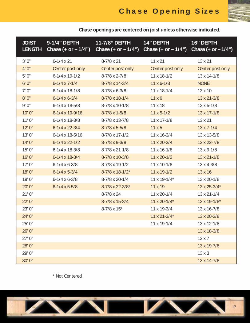
JOIST 9-1/4” DEPTH 11-7/8” DEPTH 14” DEPTH 16” DEPTHLENGTH Chase (+ or – 1/4”) Chase (+ or – 1/4”) Chase (+ or – 1/4”) Chase (+ or – 1/4”)
3’ 0” 6-1/4 x 21 8-7/8 x 21 11 x 21 13 x 21
4’ 0” Center post only Center post only Center post only Center post only
5’ 0” 6-1/4 x 19-1/2 8-7/8 x 2-7/8 11 x 18-1/2 13 x 14-1/8
6’ 0” 6-1/4 x 7-1/4 8-7/8 x 14-3/4 11 x 6-1/8 NONE
7’ 0” 6-1/4 x 18-1/8 8-7/8 x 6-3/8 11 x 18-1/4 13 x 10
8’ 0” 6-1/4 x 6-3/4 8-7/8 x 18-1/4 11 x 6 13 x 21-3/8
9’ 0” 6-1/4 x 18-5/8 8-7/8 x 10-1/8 11 x 18 13 x 5-1/8
10’ 0” 6-1/4 x 19-9/16 8-7/8 x 1-5/8 11 x 5-1/2 13 x 17-1/8
11’ 0” 6-1/4 x 18-3/8 8-7/8 x 13-7/8 11 x 17-1/8 13 x 21
12’ 0” 6-1/4 x 22-3/4 8-7/8 x 5-5/8 11 x 5 13 x 7-1/4
13’ 0” 6-1/4 x 18-5/16 8-7/8 x 17-1/2 11 x 16-3/4 13 x 13-5/8
14’ 0” 6-1/4 x 22-1/2 8-7/8 x 9-3/8 11 x 20-3/4 13 x 22-7/8
15’ 0” 6-1/4 x 18-3/8 8-7/8 x 21-1/8 11 x 16-1/8 13 x 9-1/8
16’ 0” 6-1/4 x 18-3/4 8-7/8 x 10-3/8 11 x 20-1/2 13 x 21-1/8
17’ 0” 6-1/4 x 6-3/8 8-7/8 x 19-1/2 11 x 10-1/8 13 x 4-3/8
18’ 0” 6-1/4 x 5-3/4 8-7/8 x 18-1/2* 11 x 19-1/2 13 x 16
19’ 0” 6-1/4 x 6-3/8 8-7/8 x 20-1/4 11 x 19-1/4* 13 x 20-1/8
20’ 0” 6-1/4 x 5-5/8 8-7/8 x 22-3/8* 11 x 19 13 x 25-3/4*
21’ 0” 8-7/8 x 24 11 x 20-1/4 13 x 21-1/4
22’ 0” 8-7/8 x 15-3/4 11 x 20-1/4* 13 x 19-1/8*
23’ 0” 8-7/8 x 15* 11 x 19-3/4 13 x 16-7/8
24’ 0” 11 x 21-3/4* 13 x 20-3/8
25’ 0” 11 x 19-1/4 13 x 12-1/8
26’ 0” 13 x 18-3/8
27’ 0” 13 x 7
28’ 0” 13 x 19-7/8
29’ 0” 13 x 3
30’ 0” 13 x 14-7/8
* Not Centered
Chase Opening Sizes
Chase openings are centered on joist unless otherwise indicated.

18
SIMPSONStrong Tie®
ITT
IUT
LSSU
Top Flange Hangers
Face Mount Hangers
Slope and Skew Hangers
Framing Connectors
JOIST HEIGHT MODEL NAILS UPLIFT DOWN LOAD
Header Joist (133) DF/SP SPF
JOIST WIDTH = 2-1/2
9-1/4 ITT39.37 6-10d 2-10dx1-1/2 210 1615 1200
11-7/8 ITT311.88 6-10d 2-10dx1-1/2 210 1615 1200
14 ITT314 6-10d 2-10dx1-1/2 245 1615 1200
16 ITT316 6-10d 2-10dx1-1/2 210 1615 1200
JOIST WIDTH = 3-1/2
9-1/4 ITT49.37 6-10d 2-10dx1-1/2 210 1615 1200
11-7/8 ITT411.88 6-10d 2-10dx1-1/2 210 1615 1200
14 ITT414 6-10d 2-10dx1-1/2 245 1615 1200
16 ITT416 6-10d 2-10dx1-1/2 210 1615 1200
JOIST HEIGHT MODEL NAILS UPLIFT DOWN LOAD
Header Joist (133) DF/SP SPF
JOIST WIDTH = 2-1/2
9-1/4 IUT310 8-10d 2-10dx1-1/2 210 890 770
11-7/8 IUT312 10-10d 2-10dx1-1/2 210 1110 960
14 IUT314 14-10d 2-10dx1-1/2 245 1555 1345
16 IUT316 16-10d 2-10dx1-1/2 210 1775 1535
JOIST WIDTH = 3-1/2
9-1/4 IUT410 8-10d 2-10dx1-1/2 210 890 770
11-7/8 IUT412 10-10d 2-10dx1-1/2 210 1110 960
14 IUT414 14-10d 2-10dx1-1/2 245 1555 1345
16 IUT416 16-10d 2-10dx1-1/2 210 1755 1535
JOIST HEIGHT MODEL NAILS UPLIFT DOWN LOAD
Header Joist (133) DF/SP SPF
JOIST WIDTH = 2 1/2
9-1/4 LSSUH310 14-16d 12-10dx1-1/2 990 1600 1385
11-7/8 LSSUH310 14-16d 12-10dx1-1/2 990 1600 1385
14 LSSUH310 14-16d 12-10dx1-1/2 990 1600 1385
16 LSSUH310 14-16d 12-10dx1-1/2 990 1600 1385
JOIST WIDTH = 3 1/2
9-1/4 LSSU410 14-16d 12-10dx1-1/2 990 1825 1580
11-7/8 LSSU410 14-16d 12-10dx1-1/2 990 1825 1580
14 LSSU410 14-16d 12-10dx1-1/2 990 1825 1580
16 LSSU410 14-16d 12-10dx1-1/2 990 1825 1580
Framing Connectors

19
Shaded hangers require filler block at joist ends.
45° Skew Hangers
Adjustable Height Hangers
Notes on Hanger Charts
1 a. Loads listed are based on hanger attachment to a Douglas Fir-Larch (DF) / Southern Pine (SP) or Spruce-Pine-Fire (SPF) species of LVL or solid-sawn header.
b. Down load column represents floor loading at 100% duration. Other load durations may apply; refer to the current Simpson Strong-Tie® Wood Construction Connectors catalog for allowable increases.
c. Minimum nail penetration required to achieve loads listed for face mount hangers: 10d common min. penetration = 1-3/4”; 16d common min. penetration = 2”.
d. THAI hangers require a minimum of four top and two face nails installed.
e. Uplift loads are based on an SPF joist and have been increased 33% for earthquake and wind loading with no further increase allowed. Reduce according to the code for normal loading criteria like cantilever construction.
Notes on Hanger Charts2. Hanger height less than 60% of joist height. Potential joist
rotation may occur. See Simpson catalog for additional information.
3. Top flange hanger configuration and thickness of top flange need to be considered for flush frame conditions.
4. Refer to the current Composite Wood Products Connectors catalog for hanger models not shown.
5. Joists taller than 14” require lateral restraint at the top chord (or near the top) when used with the THAI hanger. Lateral
restraint can be accomplished with filler blocks or blocking.
6. When filler blocks are required, the thickness of the filler blocks should provide an outside surface even with the outside edge of the flange.
7. All nails shown are common nails unless otherwise noted.
SIMPSONStrong Tie®
THAI
SUL/R
Framing Connectors
JOIST HEIGHT MODEL NAILS UPLIFT DOWN LOAD
Header Joist (133) DF/SP SPF
JOIST WIDTH = 2-1/2
9-1/4 THAI322 6-10d 2-10dx1-1/2 – 1835 1590
11-7/8 THAI322 6-10d 2-10dx1-1/2 – 1835 1590
14 THAI322 6-10d 2-10dx1-1/2 – 1835 1590
16 THAI322 6-10d 2-10dx1-1/2 – 1835 1590
JOIST WIDTH = 3-1/2
9-1/4 THAI422 6-10d 2-10dx1-1/2 – 1835 1590
11-7/8 THAI422 6-10d 2-10dx1-1/2 – 1835 1590
14 THAI422 6-10d 2-10dx1-1/2 – 1835 1590
16 THAI422 6-10d 2-10dx1-1/2 – 1835 1590
JOIST HEIGHT MODEL NAILS UPLIFT DOWN LOAD
Header Joist (133) DF/SP SPF
JOIST WIDTH = 2-1/2
9-1/4 SUR/L310 14-16d 6-10dx1 1/2 620 1860 1610
11-7/8 SUR/L310 14-16d 6-10dx1 1/2 620 1860 1610
14 SUR/L310 14-16d 6-10dx1 1/2 620 1860 1610
16 SUR/L314 18-16d 6-10dx1 1/2 825 2395 1795
JOIST WIDTH = 3-1/2
9-1/4 SUR/L410 14-16d 6-16d 915 1860 1610
11-7/8 SUR/L410 14-16d 6-16d 915 1860 1610
14 SUR/L410 14-16d 6-16d 915 1860 1610
16 SUR/L414 18-16d 8-16d 1220 2395 1795
Framing Connectors
20
Open Joist Specifications
This guide specification has been prepared by Universal Forest Products, Inc. to assist design professionals in the preparation of a specifica-tion section covering Open Joist open-web wood joists for use in floor framing in residen-tial and commercial projects. These joists may only be used for roof framing where the roof slope is 1/2 in. 12 or less and when adequately sized for this condition. Refer to Open Joist literature for additional information on these products.
Open Joist products can be used in fire-rated and acoustical-rated floor assemblies when combined with other building components, including cementitious toppings, subflooring, and gypsum board as applicable to the tested assembly. Refer to Open Joist literature and Web site for information on fire-rated and acoustical-rated assemblies.
This specification may be used as the basis for developing either a project specificationor an office master specification. Since it has been prepared according to the principles established in the Manual of Practice pub-lished by the Construction Specifications Institute (CSI), it may be used in conjunction with most commercially available master specification systems with minor editing.
This guide specification is available on our Web site at: www.openjoist.com
Open Joist Specifications
PART 1 - GENERAL
1.1 Summary
A. Section includes: 1. Open-web wood floor joists. 2. Bracing, blocking and accessories.
B. Related sections: 1. Division 1: Administrative, procedural, and temporary work requirements. 2. Section 06110 – Framing and Sheathing a. Wood bracing, blocking and framing for openings. b. Subflooring.
1.2 References
A. International Code Council (ICC) (www.iccsafe.org) 2006 International Building Code (IBC) 2006 International Residential Code (IRC) 1999 BOCA National Building Code/1999 (BNBC) 1999 Standard Building Code (SBC) 1997 Uniform Building Code (UBC)
B. National Institute of Standards and Technology (NIST) (www.nist.gov) PS20 American Softwood Lumber Standard.
C. Canadian Wood Council member lumber grading agencies qualified by the American Lumber Standards Board of Review.
1.3 System Description
A. Design floor loads: 1. Live load. 2. Dead load. 3. Deflection maximum.
1.4 Submittals
A. Submittals for review: 1. Shop drawings: Indicate sizes and spacing of joists and associated components, web and chord member sizes, loading, bracing and blocking, and framed openings. 2. Product data: Include joist configurations, bearing and anchor details, bracing and blocking.

21
Open Joist SpecificationsOpen Joist Specifications
1.5 Quality Assurance
A. Manufacturer: 1. Experience in manufacture of open-web wood joists. 2. Member of Wood Truss Council of America (WTCA).
B. Lumber Grading Agency: Certified to NIST PS 20.
C. Joists: Meet requirements of ICC International Building Code; certified by ICC Evaluation Service, Inc.
1.6 Delivery, Storage and Handling
A. Handle joists upright by bottom flange.
B. Prevent excessive flat-wise bending of joists.
C. For joists stored outdoors: 1. Place joists on blocks or spacers located at ends and maximum 10 feet on-center. 2. Cover joists with properly vented, waterproof coverings. 3. Do not stack joist bundles more than three high. 4. Leave joist bundle bands in place until ready to use.
PART 2 - PRODUCTS
2.1 Manufacturer
A. Contract documents are based on Open Joist by Universal Forest Products, Inc.
2.2 Materials
A. Lumber: Spruce-Pine-Fir, graded to requirements of Canadian Wood Council lumber grading agencies.
2.3 Accessories
A. Lumber for bracing, blocking and framed openings.
B. Fasteners.
2.4 Fabrication
A. Fabricate joists to achieve specified structural requirements.
PART 3 - EXECUTION
3.1 Installation
A. Install joists and accessories in accordance with manufacturer’s instructions and approved shop drawings.
B. Set joists level, plumb, right-side up, in correct position.
C. Joists may be trimmed maximum 5-1/2 inches on each end; leave minimum 1-3/4 inches of solid end block intact.
D. Do not cut, notch or drill joist top chords, bottom chords or webs.
E. Provide minimum 1-1/2 inches of bearing at each end of joists.
F. Fasten joists to top plates, bearing plates, rim boards, and other joists butting end to end or lapping at ends.
G. Place temporary 2x4 lumber bracing perpendicular to joists at maximum 8 feet on-center, spanning minimum of three joists. Fasten bracing to each joist.
H. Place triangulated 2x4 lumber bracing or 4-foot wide strip of temporary or permanent sheathing where end walls are not braced.
I. Remove temporary bracing and sheathing progressively as permanent subflooring is installed.
J. Install permanent bracing at locations indicated on shop drawings.
K. Frame openings between trusses with lumber in accordance with Architect/Engineer requirements.
L. Coordinate placement of subflooring with work of this section.
M. Installation tolerances: 1. Location of framing members: Maximum 1 inch from indicated positions.

Notes
22
Notes

Notes
23
Notes

5674-9/09
Technical inquiries: 800-584-5191
www.openjoist.com
©2006-2009 Universal Forest Products,® Inc. All rights reserved. Printed in U.S.A.
HexiTherm is a registered trademark of Hexion Specialty Chemicals, Inc., in the U.S.
Simpson Strong is a registered trademark of Simpson Strong-Tie Company Inc., in the U.S.
Universal Forest Products Eastern Division, Inc. manufactures the Open Joist product as a licensee of Distribution Open Joist 2000, Inc. All Open Joist product design and engineering calculations are created by the licensor, Distribution Open Joist 2000, Inc.