cooling system 1. general - toyota tundra forum - … engine4.0.pdfcooling system 1. general ......
TRANSCRIPT

ENGINE — 1GR-FE ENGINE EG-63
COOLING SYSTEM
1. General
The cooling system is a pressurized, forced-circulation type. A thermostat with a bypass valve is located in the water inlet housing to maintain suitable temperature
distribution in the cooling system. A viscous coupling type cooling fan is used. The engine coolant that is used is TOYOTA genuine SLLC (Super Long Life Coolant).
238EG32
To Heater Core
From Heater CoreTo Throttle Body
From Throttle Body
Thermostat
Engine Oil Cooler
Opening Temp.: 80 to 84°C(176 to 183°F)
Water Circuit
238EG33
Heater Core
Cylinder Block
Cylinder Head
Engine Oil Cooler
Thermostat
Throttle Body
Radiator
Reservoir Tank
Water Pump

ENGINE — 1GR-FE ENGINEEG-64
2. Water Pump
The water pump has two volute chambers, and circulates coolant uniformly to the left and right banks of thecylinder block.
238EG35
Cross Section
View from Back Side
Rotor
From Water Inlet Housing
Volute ChambersWater Pump
Water Pump Gasket
Timing Chain Cover
3. Cooling Fan
A viscous coupling type cooling fan is used. This fan utilizes the characteristics of a bimetal spring to switchthe fluid passages and appropriately control the silicone oil, in order to change the fan speed in three stages:OFF, middle, and high. The fan speed changes from middle to high speed in response to the temperature ofthe air passing through the radiator.
238EG36
Air Temperature PassingThrough Radiator
OFF
Middle
High
Cooling Fan Speed
Fluid Coupling Rotor
Fluid Coupling Valve
Bimetal

ENGINE — 1GR-FE ENGINE EG-65
4. TOYOTA Genuine SLLC
TOYOTA genuine SLLC (Super Long Life Coolant) is used. The maintenance interval is as shown in thetable below:
Type TOYOTA Genuine SLLC
Maintenance First Time 100000 miles (160000 km)MaintenanceIntervals Subsequent Every 50000 miles (80000 km)
Color Pink
SLLC is pre-mixed (50 % coolant and 50 % deionized water), so no dilution is needed when adding orreplacing SLLC in the vehicle.
If LLC is mixed with SLLC, the interval for LLC (every 25000 miles (U.S.A.), 32000 km (Canada) or 24months whichever come first) should be used.
You can also apply the new maintenance interval (every 50000 miles/80000 km) to vehicles initially filledwith LLC (red-colored), if you use SLLC (pink-colored) for the engine coolant change.
ENGINE — 1GR-FE ENGINE
ENGINE
EG-66
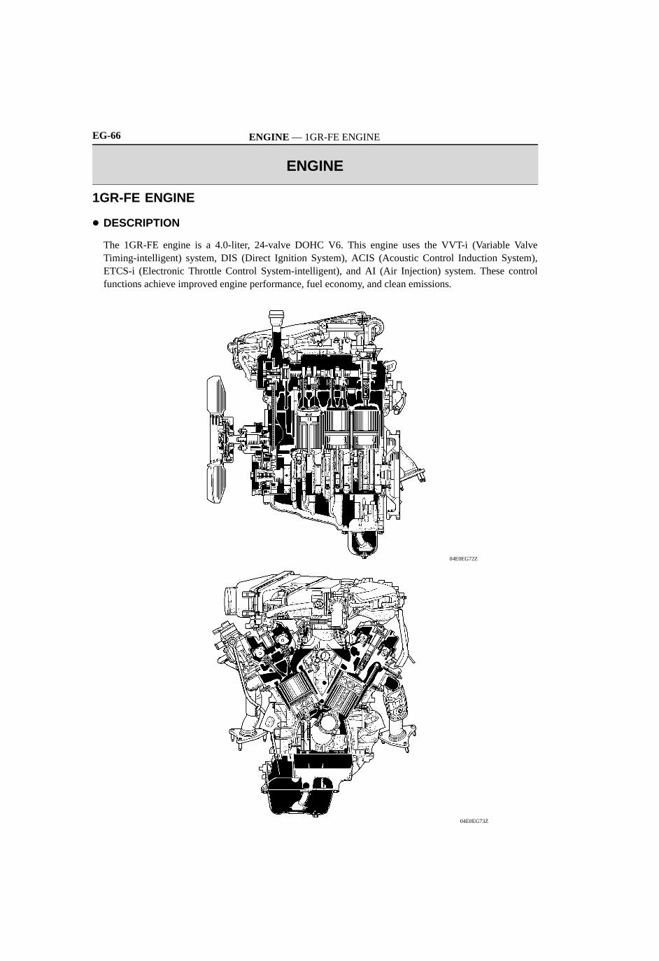
1GR-FE ENGINE
DESCRIPTION
The 1GR-FE engine is a 4.0-liter, 24-valve DOHC V6. This engine uses the VVT-i (Variable ValveTiming-intelligent) system, DIS (Direct Ignition System), ACIS (Acoustic Control Induction System),ETCS-i (Electronic Throttle Control System-intelligent), and AI (Air Injection) system. These controlfunctions achieve improved engine performance, fuel economy, and clean emissions.
04E0EG72Z
04E0EG73Z

ENGINE — 1GR-FE ENGINE EG-67
Engine Specification
Engine Type 1GR-FE
No. of Cyls. & Arrangement 6-Cylinder, V Type
Valve Mechanism 24-Valve DOHC, Chain Drive (with VVT-i)
Combustion Chamber Pentroof Type
Flow of Intake and Exhaust Gasses Cross-Flow
Fuel System SFI
Ignition System DIS
Displacement cm3 (cu. in.) 3956 (241.4)
Bore × Stroke mm (in.) 94.0 × 95.0 (3.70 × 3.74)
Compression Ratio 10.0 : 1
Max. Output (SAE-NET)*1 176 kW @ 5200 rpm(236 HP @ 5200 rpm)
Max. Torque (SAE-NET)*1 361 N⋅m @ 4000 rpm(266 ft⋅lbf @ 4000 rpm)
Dry 6.0 liters (6.3 US qts, 5.3 Imp. qts)
Oil Capacity With Oil Filter 5.2 liters (5.5 US qts, 4.6 Imp. qts)p y
Without Oil Filter 4.9 liters (5.2 US qts, 4.3 Imp. qts)
Oil Grade ILSAC
Engine CoolantType TOYOTA Genuine Super Long Life
Coolant or the following*2Engine CoolantCapacity 9.6 liters (10.1 US qts, 8.4 Imp. qts)
TypeDENSO K20HR-U11 (Nickel)
Spark PlugType
NGK LFR6C11 (Nickel)p g
Plug Gap mm (in.) 1.0 - 1.1 (0.0394 - 0.0433)
Firing Order 1 - 2 - 3 - 4 - 5 - 6
Fuel Octane Rating (RON+MON)/2 87 or higher
E i i TailpipeCalifornia LEVII, SFTP
EmissionRegulation
TailpipeExcept California Tier2-Bin5, SFTP
RegulationEvaporative LEVII, ORVR
Engine Service Mass*3 (Reference) kg (lb) 170 (374.8)
*1: Maximum output and torque rating are determined using the revised SAE J1349 procedure.*2: Similar high quality ethylene glycol based non-silicate, non-amine, non-nitrite, and non-borate coolant
with long-life hybrid organic acid technology. (Coolant with long-life hybrid organic acid technologyconsists of a combination of low phosphates and organic acids.)
*3: The figure shown is the weight of the part without coolant and oil.

ENGINE — 1GR-FE ENGINE
0240EG02C
BDC
42°
TDC: Exhaust Valve Opening Angle
: Intake Valve Opening Angle
VVT-i Operation Range
VVT-i Operation Range
2° 8°
60°
10°
54°
232°
236°
EG-68
Valve Timing
IntakeOpen 8 ATDC to 42 BTDC
IntakeClose 60 to 10 ABDC
ExhaustOpen 54 BBDC
ExhaustClose 2 ATDC
Performance Curve
04E0EG67C
1000
(HP) kW
Engine Speed (rpm)
N⋅m (ft⋅lbf)
Torque
300
Output
60005000400030002000
400380360340320300280
280
260
240
220
200
260
180
120
140
160
100
80
60
40
20
0
240
220
20
40
60
80
100
120
140
160
180
200
0

ENGINE — 1GR-FE ENGINE EG-69
FEATURES OF 1GR-FE ENGINE
The 1GR-FE engine has achieved the following performance through the use of the items listed below.
(1) High performance and reliability(2) Low noise and vibration(3) Lightweight and compact design(4) Good serviceability(5) Clean emissions and fuel economy
Item (1) (2) (3) (4) (5)
Upright intake ports are used.
A taper squish shape is used for the combustion chamber.
A steel laminate type cylinder head gasket is used.
Engine Proper A cylinder block made of aluminum alloy is used.
The skirt portion of the pistons have a resin coating applied toreduce friction.
An oil pan (oil pan No.1) made of aluminum alloy is used.
A VVT-i (Variable Valve Timing-intelligent) system is used.
Valve Mechanism Shim-less type valve lifters are used.
Timing chains (3) and chain tensioners are used.
Cooling System The engine coolant that is used is the TOYOTA GenuineSLLC (Super Long Life Coolant).
A carbon filter is used in the air cleaner case.
Intake and A cable-less type throttle body is used. Intake and Exhaust System An intake air chamber made of plastic is used.
Stainless steel exhaust manifolds are used.
Fuel System
12-hole type fuel injectors are used to improve theatomization of fuel.
Fuel System
A fuel delivery pipe that is made of plastic is used.
Ignition System The DIS (Direct Ignition System) makes ignition timingadjustment unnecessary.
Charging System A segment conductor type generator is used.
Starting System A PS type starter is used.
Serpentine BeltDrive System
A serpentine belt drive system is used.
MRE (Magnetic Resistance Element) type VVT sensors areused.
Engine Control
The ETCS-i (Electronic Throttle Control System-intelligent)is used.
Engine ControlSystem An ACIS (Acoustic Control Induction System) is used. System
An air injection system is used.
The cranking hold function is used.
An evaporative emission control system is used.

ENGINE — 1GR-FE ENGINE EG-73
6. Exhaust Manifold
A stainless steel exhaust manifold is used for weight reduction. Along with the adoption of the air injection system, air injection pipes are provided for the right and left
bank exhaust manifolds.
04E0EG07C
Air Injection Pipe
Exhaust Manifold(For Left Bank)
Gaskets
Air Injection Pipe
Exhaust Manifold(For Right Bank)
7. Exhaust Pipe
A stainless steel exhaust pipe is used for weight reduction and rust resistance. Two ceramic type TWCs (Three-Way Catalytic converter) are provided in the exhaust front pipe for the
left bank and also two for the right bank. The exhaust emission performance of the engine is improved asa result of these TWCs.
04E1EG72C
TWC
TWC
ENGINE — 1GR-FE ENGINE EG-77
ENGINE PROPER
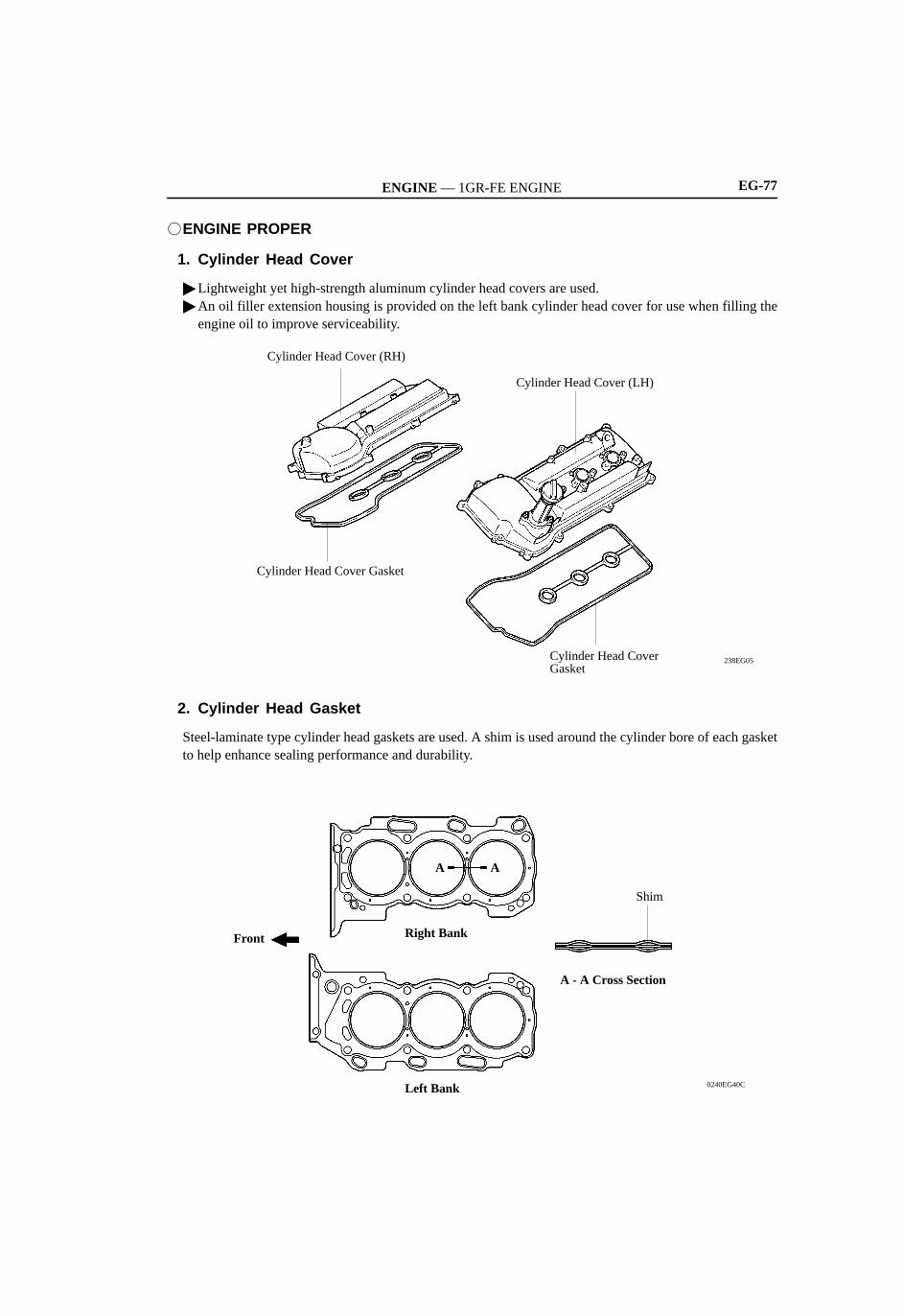
1. Cylinder Head Cover
Lightweight yet high-strength aluminum cylinder head covers are used. An oil filler extension housing is provided on the left bank cylinder head cover for use when filling the
engine oil to improve serviceability.
238EG05Cylinder Head Cover Gasket
Cylinder Head Cover (LH)
Cylinder Head Cover Gasket
Cylinder Head Cover (RH)
2. Cylinder Head Gasket
Steel-laminate type cylinder head gaskets are used. A shim is used around the cylinder bore of each gasketto help enhance sealing performance and durability.
0240EG40C
Shim
A - A Cross Section
Right BankFront
Left Bank
A A

ENGINE — 1GR-FE ENGINEEG-78
3. Cylinder Head
The cylinder head, which is made of aluminum, contains a pentroof-type combustion chamber. The sparkplug is located in the center of the combustion chamber in order to improve the engine’s anti-knockingperformance.
The intake ports are on the inside and the exhaust ports are on the outside of the left and right banksrespectively.
Upright intake ports are used to improve the intake efficiency. A taper squish combustion chamber is used to improve anti-knocking performance and intake efficiency.
In addition, engine performance and fuel economy are improved. Siamese type intake ports are used to reduce the overall surface area of the intake port walls. This prevents
the fuel from adhering to the intake port walls, thus reducing HC exhaust emissions. The air injection port is provided for the air injection system. For details, see page EG-65.
04E0EG01C
Taper SquishUpright Intake Port
IN
Exhaust Valve
Intake Valve
Spark Plug Hole
View from Back Side
A
A
A - A Cross Section
EX
238EG08
Air Injection Port
— REFERENCE —
215EG19
Siamese Type Independent Type
215EG18
ENGINE — 1GR-FE ENGINE EG-79
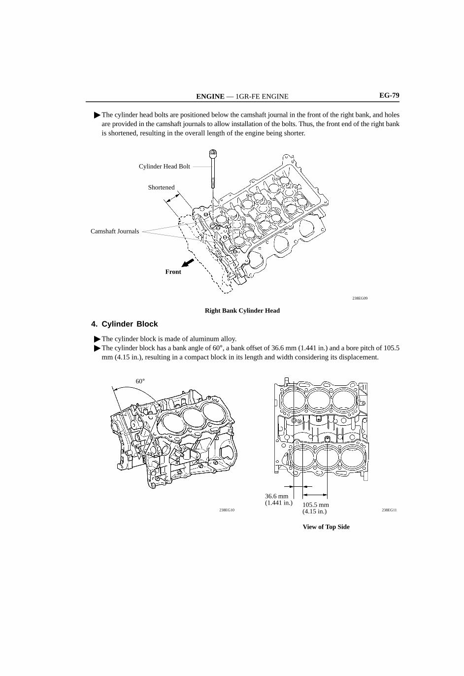
The cylinder head bolts are positioned below the camshaft journal in the front of the right bank, and holesare provided in the camshaft journals to allow installation of the bolts. Thus, the front end of the right bankis shortened, resulting in the overall length of the engine being shorter.
238EG09
Cylinder Head Bolt
Shortened
Camshaft Journals
Front
Right Bank Cylinder Head
4. Cylinder Block
The cylinder block is made of aluminum alloy. The cylinder block has a bank angle of 60°, a bank offset of 36.6 mm (1.441 in.) and a bore pitch of 105.5
mm (4.15 in.), resulting in a compact block in its length and width considering its displacement.
238EG11238EG10
60°
36.6 mm (1.441 in.) 105.5 mm
(4.15 in.)
View of Top Side
ENGINE — 1GR-FE ENGINEEG-80
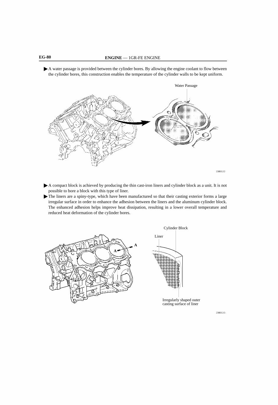
A water passage is provided between the cylinder bores. By allowing the engine coolant to flow betweenthe cylinder bores, this construction enables the temperature of the cylinder walls to be kept uniform.
238EG12
Water Passage
A compact block is achieved by producing the thin cast-iron liners and cylinder block as a unit. It is notpossible to bore a block with this type of liner.
The liners are a spiny-type, which have been manufactured so that their casting exterior forms a largeirregular surface in order to enhance the adhesion between the liners and the aluminum cylinder block.The enhanced adhesion helps improve heat dissipation, resulting in a lower overall temperature andreduced heat deformation of the cylinder bores.
238EG13
Liner
Cylinder Block
Irregularly shaped outercasting surface of liner
A
A
ENGINE — 1GR-FE ENGINE EG-81
FUEL SYSTEM
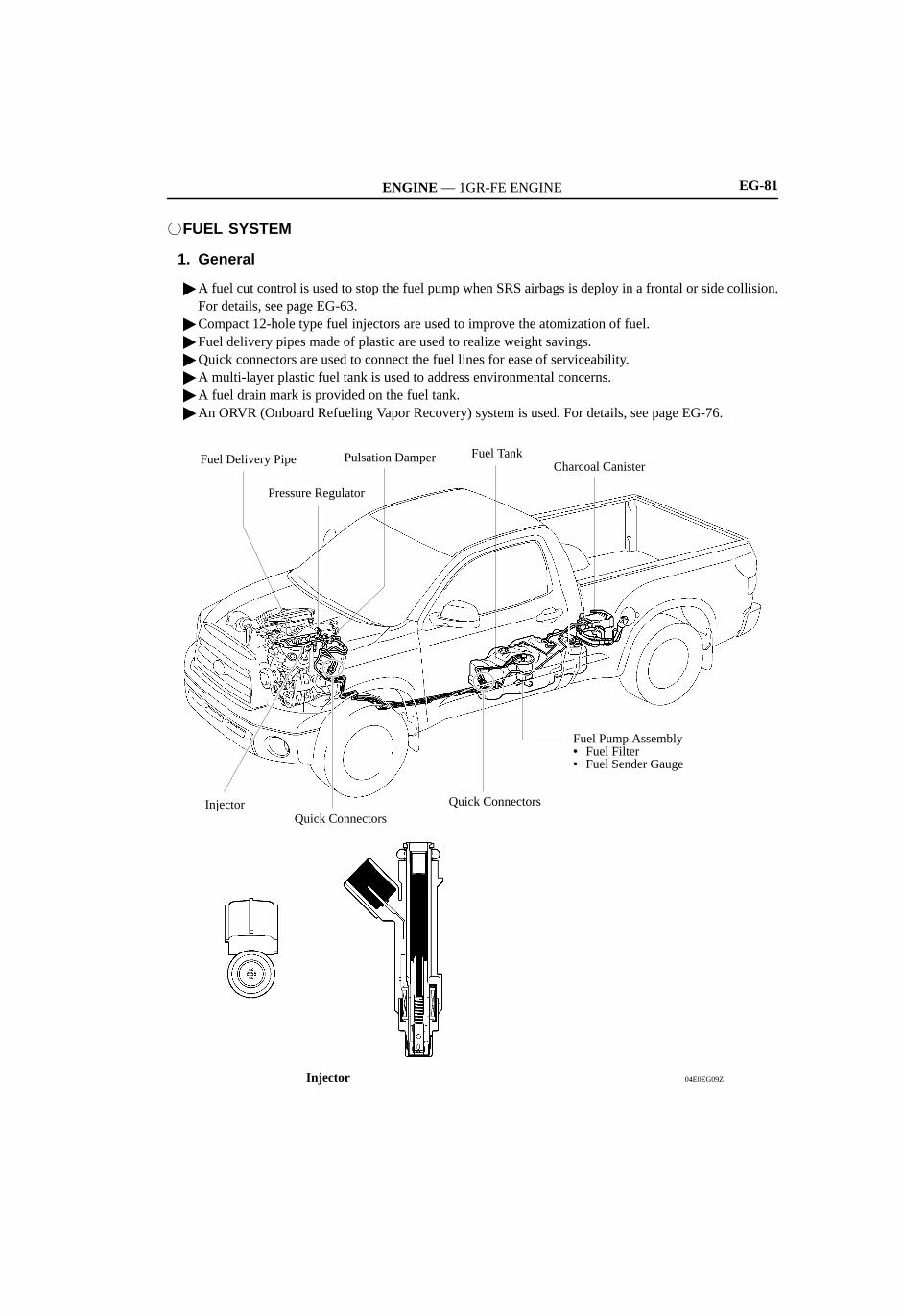
1. General
A fuel cut control is used to stop the fuel pump when SRS airbags is deploy in a frontal or side collision.For details, see page EG-63.
Compact 12-hole type fuel injectors are used to improve the atomization of fuel. Fuel delivery pipes made of plastic are used to realize weight savings. Quick connectors are used to connect the fuel lines for ease of serviceability. A multi-layer plastic fuel tank is used to address environmental concerns. A fuel drain mark is provided on the fuel tank. An ORVR (Onboard Refueling Vapor Recovery) system is used. For details, see page EG-76.
04E0EG09Z
Quick ConnectorsInjector
Injector
Quick Connectors
Fuel Pump Assembly• Fuel Filter• Fuel Sender Gauge
Charcoal CanisterFuel TankPulsation Damper
Pressure Regulator
Fuel Delivery Pipe

ENGINE — 1GR-FE ENGINE
Service Tip
04E0EG10C
Fuel Drain Mark
EG-82
A fuel drain mark has been provided at the fuel tank. When dismantling (scrapping) the vehicle, drainthe fuel by making a hole at this mark.
2. Fuel Tank
The multi-layer plastic fuel tank consists of six layers of four types of materials, and one of those is arecyclable material to address environmental concerns.
D13N27
Recyclable Material
Ethylene Vinyl Alcohol Copolymer
High Density Polyethylene
Cross Section of Fuel Tank
Exterior of Fuel Tank
Adhesive
Interior of Fuel Tank
High Density Polyethylene

ENGINE — 1GR-FE ENGINE
Service Tip
EG-83
VALVE MECHANISM
1. General
The intake camshafts are driven by the crankshaft via the primary timing chain. The intake camshaft ofthe respective bank drives the exhaust camshafts via the secondary timing chain.
The valves are directly opened and closed by the 4 camshafts. The VVT-i controller is installed on the front of the intake camshafts to vary the timing of the intake valves. Along with increase in the amount of valve lift, a shimless type valve lifter is used. This valve lifter raises
the cam contact surface.
0240EG05C
Cross Section of Valve Mechanism
Valve
Valve Lifter
Exhaust Camshaft (For Left Bank)
Intake Camshaft (For Left Bank)
Intake Camshaft (For Right Bank)
Timing Chain (Secondary)
Timing Chain (Primary)
VVT-i Controller (For Right Bank)
Exhaust Camshaft (For Right Bank)
VVT-i Controller (For Left Bank)
The adjustment of the valve clearance is accomplished by selecting and replacing the appropriate valvelifters.A total of 35 valve lifters are available in 0.020 mm (0.008 in.) increments, from 5.060 mm (0.199 in.)to 5.740 mm (0.226 in.). For details, refer to the 2007 TOYOTA TUNDRA Repair Manual (Pub. No.RM04E2U).

ENGINE — 1GR-FE ENGINEEG-84
2. Camshaft
The camshafts are made of a cast iron alloy. Oil passages are provided in the intake camshaft in order to supply engine oil to the VVT-i system. A timing rotor is provided in front of the VVT-i controller to detect the actual position of the intake
camshaft.
0240EG06C
No.4 Camshaft (Exhaust)
No.3 Camshaft (Intake)
No.1 Camshaft (Intake)
Timing Rotor
Cross Section of the End of the Intake Camshaft
Oil Passage
VVT-i Controllers
Timing Rotor
No.2 Camshaft (Exhaust)
ENGINE — 1GR-FE ENGINE EG-85
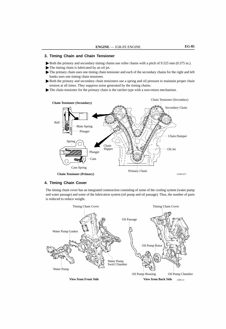
3. Timing Chain and Chain Tensioner
Both the primary and secondary timing chains use roller chains with a pitch of 9.525 mm (0.375 in.). The timing chain is lubricated by an oil jet. The primary chain uses one timing chain tensioner and each of the secondary chains for the right and left
banks uses one timing chain tensioner. Both the primary and secondary chain tensioners use a spring and oil pressure to maintain proper chain
tension at all times. They suppress noise generated by the timing chains. The chain tensioner for the primary chain is the ratchet type with a non-return mechanism.
0240EG07C
Primary Chain
Oil Jet
Chain Damper
Secondary Chain
Chain Tensioner (Secondary)
Chain Slipper
Chain Tensioner (Primary)
Cam Spring
Cam
Plunger
Spring
Plunger
Main SpringBall
Chain Tensioner (Secondary)
4. Timing Chain Cover
The timing chain cover has an integrated construction consisting of some of the cooling system (water pumpand water passage) and some of the lubrication system (oil pump and oil passage). Thus, the number of partsis reduced to reduce weight.
238EG23
Oil Pump ChamberOil Pump Housing
Oil Pump Rotor
Timing Chain Cover
Oil Passage
View from Front Side
Water PumpSwirl Chamber
Water Pump
Timing Chain Cover
Water Pump Gasket
View from Back Side
ENGINE — 1GR-FE ENGINEEG-86
LUBRICATION SYSTEM
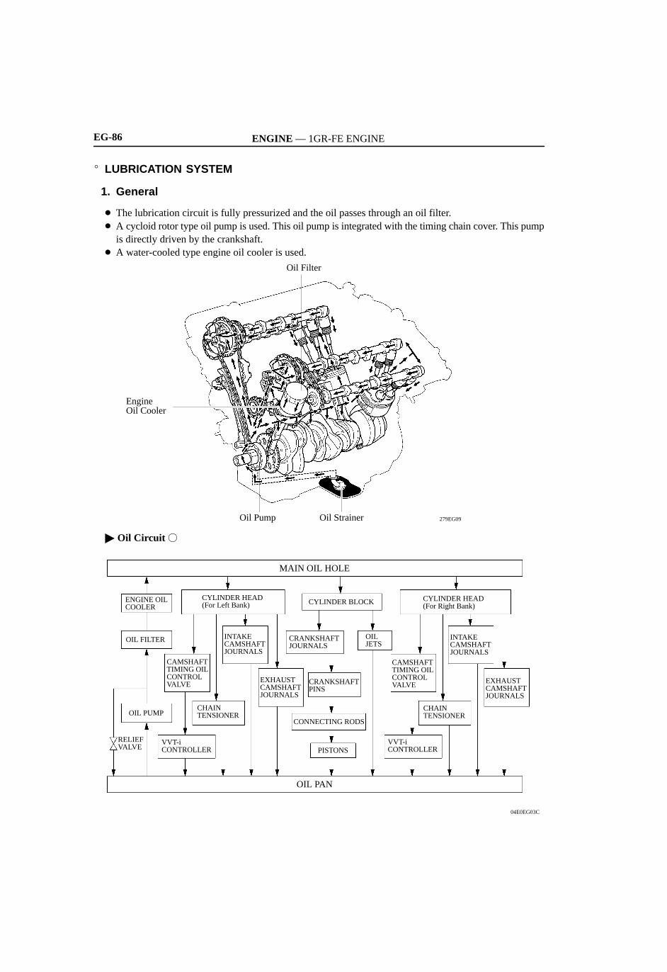
1. General
The lubrication circuit is fully pressurized and the oil passes through an oil filter. A cycloid rotor type oil pump is used. This oil pump is integrated with the timing chain cover. This pump
is directly driven by the crankshaft. A water-cooled type engine oil cooler is used.
279EG09Oil Pump
Oil Filter
Oil Strainer
EngineOil Cooler
Oil Circuit
04E0EG03C
MAIN OIL HOLE
OIL PAN
RELIEF VALVE
EXHAUST CAMSHAFTJOURNALS
VVT-iCONTROLLER
CHAINTENSIONER
INTAKE CAMSHAFTJOURNALS
CAMSHAFTTIMING OILCONTROLVALVE
CYLINDER HEAD (For Right Bank)
OIL JETS
PISTONS
CONNECTING RODS
CRANKSHAFT PINS
CYLINDER BLOCK
EXHAUSTCAMSHAFTJOURNALS
CRANKSHAFTJOURNALS
VVT-iCONTROLLER
CHAINTENSIONER
INTAKE CAMSHAFTJOURNALS
OIL PUMP
CAMSHAFTTIMING OILCONTROLVALVE
CYLINDER HEAD(For Left Bank)
OIL FILTER
ENGINE OILCOOLER

ENGINE — 1GR-FE ENGINE EG-87
2. Oil Pump
Ordinarily, the timing chain cover with oil pump construction has only a single position for mounting the oilpump rotor to the crankshaft, when installing the timing chain cover.However, in this engine, the inner shape of the oil pump rotor and the shape of the area of the crankshaft onwhich the rotor is mounted are designed to provide 4 different assembly patterns. Thus, the serviceability forassembling the timing chain cover is improved.
279EG10
View from A
Crankshaft
Oil PumpRotor
Crankshaft
A
Timing Chain Cover
3. Oil Jet
Oil jets for cooling and lubricating the pistons are provided in the cylinder block, in the center of the rightand left banks.
These oil jets contain a check valve to prevent oil from being fed when the oil pressure is low. This preventsthe overall oil pressure in the engine from dropping.
238EG28
Oil
Check Valve
Oil Jets
Oil Jet Cross Section

ENGINE — 1GR-FE ENGINE
Service Tip
0240EG11C 0240EG12C
Drain Hose
Container
EG-88
4. Oil Filter Bracket
The oil filter is mounted on an oil filter bracket placed on the left bank. Therefore, the oil filter can bereplaced easily.
During an oil filter replacement, the filter is removed from the top. Therefore, the oil filter bracket isdesigned to catch the oil that leaks from the oil filter. The oil that is initially caught by the oil filter bracketis discharged from a drain pipe that is provided underneath it.
04E0EG04C
Oil Filter Bracket
Drain Pipe with Cap
Oil Filter
Before removing the oil filter, prepare to catch the oil that will be discharged from the drain pipe. Usea container to catch the oil as illustrated below, or attach a hose to the drain pipe and catch the oil ona tray.
After completing the oil drain operation, do not forget to reinstall the rubber cap on the drain pipe.

ENGINE — 1GR-FE ENGINE EG-89
STARTING SYSTEM
1. General
A compact and lightweight PS (Planetary reduction-Segment conductor motor) type starter is standard. AnRA (Reduction Armature) type starter is used for cold weather specification vehicles.
0240EG24C
Length
RA Type StarterPS Type Starter
Length275TU06
Specifications
Type PS RA
Rated Output 1.6 kW 2.0 kW
Rated Voltage 12 V
Length 126.4 mm (4.98 in.) 185.3 mm (7.30 in.)
Weight 2800 g (6.2 lb) 4700 g (10.4 lb)
Rotation Direction Clockwise (Viewed from pinion end)

ENGINE — 1GR-FE ENGINEEG-90
2. PS starter
General
The PS starter contains an armature that uses square-shaped conductors. The surface of the armature atone end functions as the commutator, resulting in improved output torque and overall length reduction.
In place of the field coil used in the conventional starter, the PS starter uses two types of permanentmagnets: main magnets and interpolar magnets. The main magnets and interpolar magnets have beenefficiently arranged to increase the magnetic flux and to shorten the length of the yoke.
04E0EG11C
Brush
Permanent Magnet
SurfaceCommutator
Armature Brush
Armature
Yoke
206EG18
Construction
Instead of the round-shaped conductor wires used in the conventional starter, the PS type starter usessquare-shaped conductors. In this type of construction, square-shaped conductors can achieve the sameconditions as those achieved by winding numerous round-shaped conductor wires, but withoutincreasing the mass. As a result, the output torque is increased, and the armature coil is more compact.
Because the surface of the square-shaped conductors that are used in the armature coil functions as acommutator, the overall length of the PS type starter has been shortened.
206EG20
A - A Cross Section(PS Type)
Round-ShapedConductor Wire
Square-Shaped Conductor
B
Surface CommutatorArmature
PS Starter
Brush
Commutator
BrushArmature
Conventional Type Starter
B
A
A B - B Cross Section(Conventional Type)

ENGINE — 1GR-FE ENGINE EG-91
Instead of the field coils used in the conventional starter, the PS type starter uses two types of permanentmagnets: the main magnets and the interpolar magnets. The main and interpolar magnets are arrangedalternately inside the yoke. This allows the magnetic flux generated between the main and interpolarmagnets to be added to the magnetic flux generated by the main magnets. In addition to increasing theamount of magnetic flux, this construction shortens the overall length of the yoke.
264EG14
N
Magnetic Flux Generated byMain Magnets
Magnetic Flux Generated by Relationshipbetween Main and Interpolar Magnets
Cross Section of Yoke Portion
Armature
Main Magnets
Yoke
Interpolar Magnets
S
N N
N
N
S
S S
S

ENGINE — 1GR-FE ENGINE
206EG42
Stator of Segment Conductor Type Generator
Cross Section
Segment Conductor
Stator
EG-96
CHARGING SYSTEM
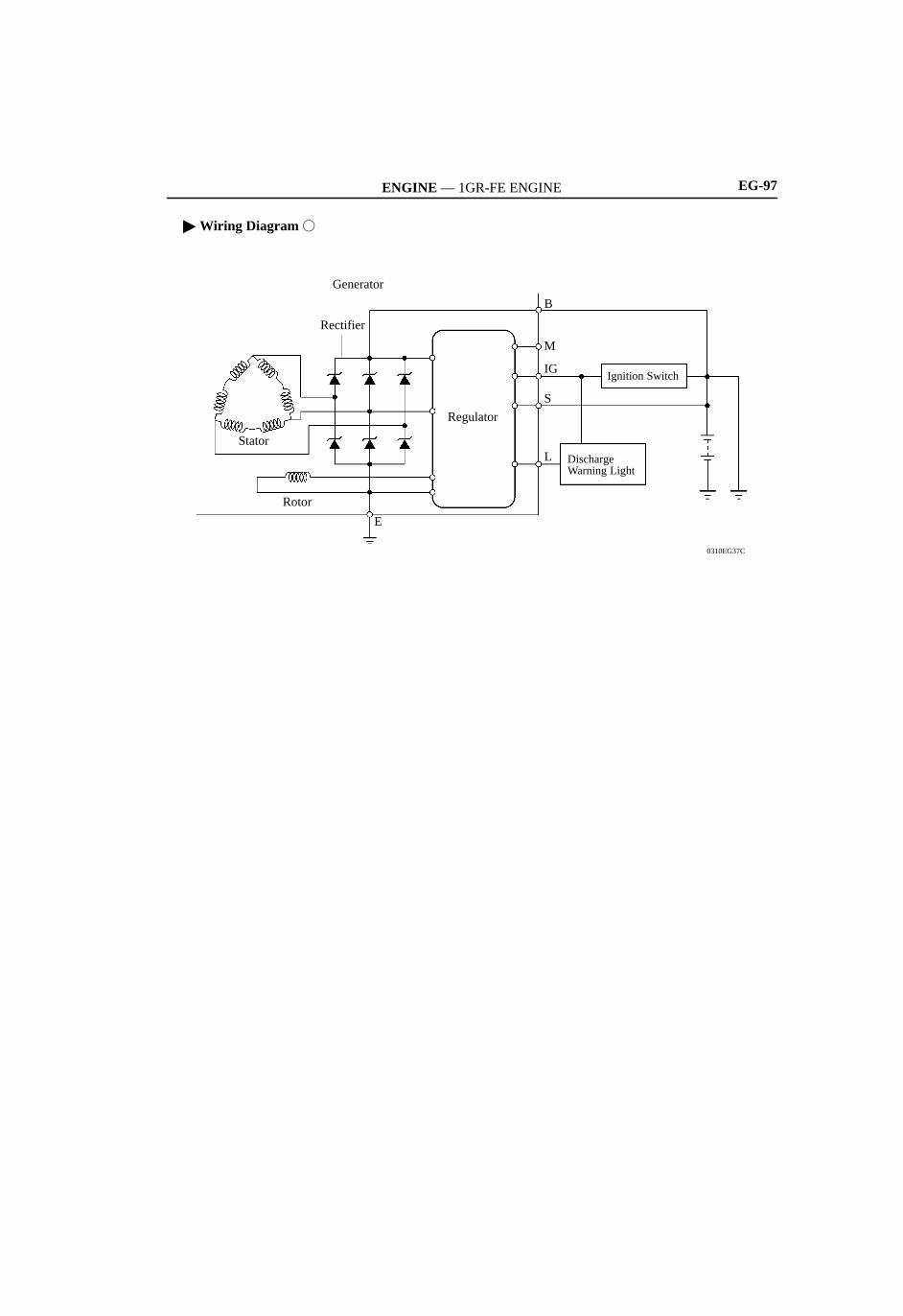
A compact and lightweight segment conductor type generator (alternator) is used. This type of generatorgenerates a high amperage output in a highly efficient manner. This generator uses a joined segment conductor system, in which multiple segment conductors are welded
together at the stator. Compared to the conventional winding system, the electrical resistance is reduceddue to the shape of the segment conductors, and their arrangement helps to make the generator morecompact.
206EG41
Wiring System
Conductor Wire
ConductorWire
A
A - A CrossSection
Segment Conductor
Segment Conductor Type Generator
Joined
Joined SegmentConductor System
StatorSegmentConductorStator
206EG40
A
B
B
B - B CrossSection
Stator Stator
Conventional Type Generator
Specifications
Type Segment Conductor
Rated Voltage 12 V
Rated Output 100 A
ENGINE — 1GR-FE ENGINE EG-97
Wiring Diagram
0310EG37C
DischargeWarning Light
Ignition Switch
B
E
Regulator
Rotor
Stator
Rectifier
Generator
L
S
M
IG

ENGINE — 1GR-FE ENGINEEG-98
4. Engine Control System Diagram
04E1EG75C
Air Fuel Ratio Sensor (Bank 1, Sensor 1)
Heated Oxygen Sensor(Bank 1, Sensor 2)
Crankshaft Position Sensor
Engine CoolantTemp. Sensor
VVT Sensor RH
KnockSensor
VVT Sensor LH
Camshaft TimingOil Control Valve LH
TWC
Heated Oxygen Sensor(Bank 2, Sensor 2)
Air Fuel Ratio Sensor(Bank 2, Sensor 1)
Air Injection Control Driver (Bank 2)
Injector
Camshaft Timing Oil Control Valve RH
Intake AirTemp. Sensor
Stop Light Switch
Generator
Airbag Sensor Assembly
ECM
EVAP Valve
Throttle Control Motor
PumpModule
PressureSensor(For EVAP)
Canister Vent Valve
Fuel Pump
Battery
Accelerator Pedal Position Sensor
DLC3
CAN
A/C AmplifierACC Cut Relay
Electronic Controlled Transmission Solenoid Valve
Starter
Park/NeutralPosition Switch
Fuel Pump ECU
Circuit Opening Relay
Starter Relay
Ignition Switch
Combination Meter• Vehicle Speed Signal• MIL
Power Steering Oil Pressure Switch
*3
Injector
Mass AirFlow Meter
Throttle PositionSensor
VSV(For ACIS)
*1
TWC TWC
TWC
*4*5
*2*6
*7
*8
*1: Air Injection Control Driver (Bank 1) *2: Ignition Coil with Igniter *3: Electric Air Pump (Bank 2)*4: Air Pressure Sensor (Bank 2) *5: Air Injection Control Valve (Bank 2) *6: Air Injection Control Valve (Bank 1)*7: Air Pressure Sensor (Bank 1) *8: Electric Air Pump (Bank 1)

ENGINE — 1GR-FE ENGINEEG-92
SERPENTINE BELT DRIVE SYSTEM
1. General
Accessory components are driven by a serpentine belt consisting of a single V-ribbed belt. It reduces theoverall engine length, weight and number of engine parts.
An automatic tensioner eliminates the need for tension adjustment.
238EG48
Air ConditioningCompressor Pulley
Idler Pulley for Automatic Tensioner
Generator Pulley
Belt Idler
Crankshaft Pulley
Belt Idler
Belt Idler
Water Pump Pulley
Power Steering Pump Pulley
2. Automatic Tensioner
The tension of the V-ribbed belt is properly maintained by the tension spring that is enclosed in the automatictensioner.
279EG62
Fulcrum
Force of Tensioner
Force of Belt
Spring
Bracket
Cross Section
Arm
Idler Pulley

ENGINE — 1GR-FE ENGINE EG-93
ENGINE CONTROL SYSTEM
1. General
The engine control system of the 1GR-FE engine has the following features. The ECM that controls thissystem is made by DENSO.
System Outline
SFI(Sequential Multiport Fuel Injection)[See page EG-52]
A L-type SFI system detects the intake air volume with a hot-wire typemass air flow meter.
ESA(Electronic Spark Advance)
• This ECM determines the optimal ignition timing in accordance withthe signals received from the sensors and sends (IGT) ignition signalto the igniter.
• The ECM corrects ignition timing in response to engine knocking.
ETCS-i(Electronic Throttle ControlSystem-intelligent)[See page EG-53]
Optimally controls the opening angle of the throttle valve in accordancewith the accelerator pedal input and the engine and vehicle conditions.
VVT-i(Variable Valve Timing-intelligent)[See page EG-55]
Controls the intake camshafts to optimal valve timing in accordance withthe engine condition.
ACIS(Acoustic Control Induction System)[See page EG-60]
The intake air passages are switched based on engine speed and throttlevalve opening angle to provide high performance in all engine speedranges.
Fuel Pump Control[See page EG-63]
• Based on signals from the ECM, the Fuel Pump ECU controls the fuelpump to 3 stages.
• The fuel pump is stopped when the SRS airbag is deployed in a frontal,side, or side rear collision.
Air Injection Control[See page EG-65]
The ECM controls the air injection time based on the signals from thecrankshaft position sensor, engine coolant temp. sensor, mass air flowmeter and air pressure sensor.
Cranking Hold Function(Starter Control)[See page EG-69]
Once the ignition switch is turned to the START position, this controloperates the starter until the engine starts.
Air Fuel Ratio Sensor and OxygenSensor Heater Control
Maintains the temperature of the air fuel ratio sensors or oxygen sensorsat an appropriate level to increase the detection accuracy of the exhaustgas oxygen concentration.
Evaporative Emission Control[See page EG-71]
• The ECM controls the purge flow of evaporative emission (HC) in thecharcoal canister in accordance with engine conditions.
• Approximately five hours after the ignition switch has been turnedOFF, the ECM operates the pump module to detect any evaporativeemission leakage occurring between the fuel tank and the charcoalcanister. The ECM can detect leaks by monitoring for changes in thefuel tank pressure.
Air Conditioning Cut-off Control By turning the air conditioning compressor ON or OFF in accordancewith the engine condition, drivability is maintained.
Diagnosis[See page EG-83]
When the ECM detects a malfunction, the ECM records the malfunctionand memorizes information related to the fault.
Fail-Safe[See page EG-83]
When the ECM detects a malfunction, the ECM stops or controls theengine according to the data already stored in the memory.

ENGINE — 1GR-FE ENGINE
238EG69
Secondary Winding
Primary Winding
Ignition Coil Cross Section
Plug Cap
Iron Core
Igniter
EG-94
IGNITION SYSTEM
1. General
A DIS (Direct Ignition System) is used. The DIS improves ignition timing accuracy, reduces high-voltageloss, and enhances the overall reliability of the ignition system by eliminating the distributor.The DIS is an independent ignition system which has one ignition coil (with an integrated igniter) for eachcylinder.
238EG68
Ignition Coil with Igniter
IGT1
ECM
Various Sensors
CrankshaftPosition Sensor
VVT Sensors
IGT4
IGT3
IGT2
IGF
IGT6
IGT5
2. Ignition Coil
The DIS provides 6 ignition coils, one for eachcylinder. The spark plug caps, which provide contactto spark plugs, are integrated with the ignition coil.Also, an igniter is enclosed to simplify the system.
ENGINE — 1GR-FE ENGINE EG-95
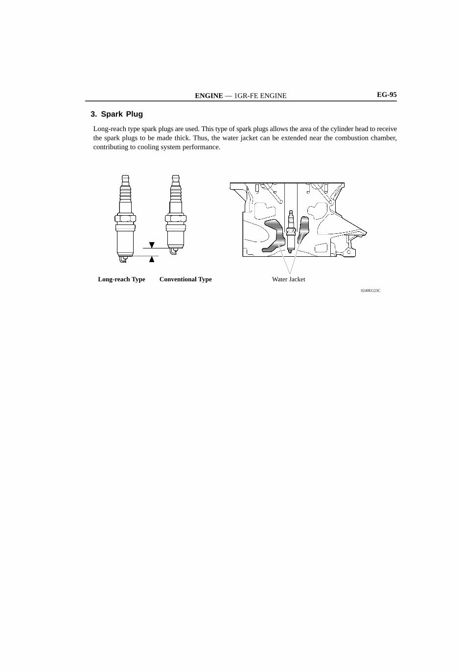
3. Spark Plug
Long-reach type spark plugs are used. This type of spark plugs allows the area of the cylinder head to receivethe spark plugs to be made thick. Thus, the water jacket can be extended near the combustion chamber,contributing to cooling system performance.
0240EG23C
Water JacketLong-reach Type Conventional Type

ENGINE — 1GR-FE ENGINEEG-108
8. Main Components of Engine Control System
General
The main components of the 1GR-FE engine control system are as follows:
Components Outline Quantity
ECM (Supplier) 32-bit CPU (DENSO) 1
Mass Air Flow Meter(Built-in Intake Air Temperature Sensor)
Hot-wire Type 1
Crankshaft Position Sensor (Rotor Teeth) Pick-up Coil Type (36 - 2) 1
VVT Sensors (Rotor Teeth) MRE (Magnetic Resistance Element) Type (3) 2(1 each bank)
Accelerator Pedal Position Sensor Linear (Non-Contact) Type 1
Throttle Position Sensor Linear (Non-Contact) Type 1
Knock Sensors Built-in Piezoelectric Type(Non-resonant Type/Flat Type)
2(1 each bank)
Air Fuel Ratio SensorsBank 1, Sensor 1
Heated Type (Planar Type) 2Air Fuel Ratio SensorsBank 2, Sensor 1
Heated Type (Planar Type) 2(1 each bank)
Heated Oxygen SensorsBank 1, Sensor 2
Heated Type (Cup Type) 2Heated Oxygen SensorsBank 2, Sensor 2
Heated Type (Cup Type) 2(1 each bank)
Injectors 12-hole Type 6
ENGINE — 1GR-FE ENGINE EG-109
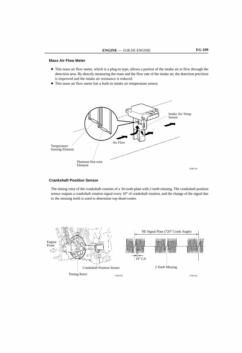
Mass Air Flow Meter
This mass air flow meter, which is a plug-in type, allows a portion of the intake air to flow through thedetection area. By directly measuring the mass and the flow rate of the intake air, the detection precisionis improved and the intake air resistance is reduced.
This mass air flow meter has a built-in intake air temperature sensor.
204EG54
Intake Air Temp. Sensor
Air Flow
Platinum Hot-wire Element
Temperature Sensing Element
Crankshaft Position Sensor
The timing rotor of the crankshaft consists of a 34 tooth plate with 2 teeth missing. The crankshaft positionsensor outputs a crankshaft rotation signal every 10° of crankshaft rotation, and the change of the signal dueto the missing teeth is used to determine top-dead-center.
279EG50
2 Teeth Missing
10° CA
NE Signal Plate (720° Crank Angle)
Crankshaft Position Sensor
Timing Rotor
Engine Front
279EG49
ENGINE — 1GR-FE ENGINEEG-110
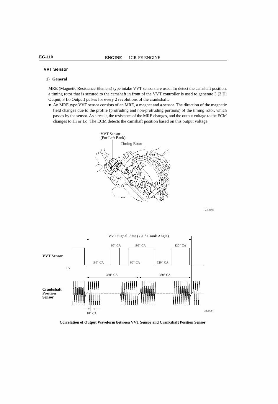
VVT Sensor
1) General
MRE (Magnetic Resistance Element) type intake VVT sensors are used. To detect the camshaft position,a timing rotor that is secured to the camshaft in front of the VVT controller is used to generate 3 (3 HiOutput, 3 Lo Output) pulses for every 2 revolutions of the crankshaft. An MRE type VVT sensor consists of an MRE, a magnet and a sensor. The direction of the magnetic
field changes due to the profile (protruding and non-protruding portions) of the timing rotor, whichpasses by the sensor. As a result, the resistance of the MRE changes, and the output voltage to the ECMchanges to Hi or Lo. The ECM detects the camshaft position based on this output voltage.
275TU15
Timing Rotor
VVT Sensor (For Left Bank)
285EG84
VVT Signal Plate (720 Crank Angle)
VVT Sensor
180 CA
CrankshaftPositionSensor
0 V
10 CA
180 CA 120 CA60 CA
120 CA60 CA
360 CA 360 CA
Correlation of Output Waveform between VVT Sensor and Crankshaft Position Sensor

ENGINE — 1GR-FE ENGINE EG-111
2) MRE Type VVT Sensor
The differences between an MRE type VVT sensor and a pickup coil type VVT sensor are as follows.
Sensor Type MRE Type Sensor Pick-up Coil Type Sensor
Signal Output Constant digital output starts from low enginespeed.
Analog output changes with the engine speed.
CamshaftPositionDetection
Camshaft position detection is made bycomparing the NE signal with the Hi/Lo outputswitch timing of the VVT sensor which is dueto the protruding/non-protruding portions ofthe timing rotor. Camshaft detection can alsobe made based on the number of the NE(engine speed) signals input during a Hi/Looutput cycle.
Detection is made by comparing the NEsignals with the change of waveform that isoutput when the protruding portion of thetiming rotor passes.
MRE Type and Pick-up Coil Type output Waveform Image Comparison
Engine Speed
Engine Speed
Sensor Output
Sensor Output
No Detection
Analog Output
Digital Output
MRE Type Pick-up Coil Type232CH41

ENGINE — 1GR-FE ENGINEEG-112
Accelerator Pedal Position Sensor
This non-contact type accelerator pedal position sensor uses a Hall IC, which is mounted on the acceleratorpedal arm. The magnetic yoke that is mounted at the base of the accelerator pedal arm moves around the Hall IC
in accordance with the amount of effort that is applied to the accelerator pedal. The Hall IC converts thechanges in the magnetic flux that occur into electrical signals, and outputs them in the form of acceleratorpedal position signals to the ECM.
This accelerator pedal position sensor includes 2 Hall ICs and circuits for the main and sub signals. Itconverts the accelerator pedal depression angles into 2 electric signals with differing characteristics andoutputs them to the ECM.
04E0EG19C
Accelerator Pedal Arm
Magnetic Yoke
Sensor Housing
Hall IC
285EG72
VPAVCPA
HallIC
VPA2
HallIC
Magnet
Accelerator Pedal Position Sensor
Accelerator Pedal Arm
ECM
V
228TU25
VPA
VPA2
Accelerator Pedal Depression Angle
FullyClosed
5
OutputVoltage
0
FullyOpen
EPA2
VCP2
EPA

ENGINE — 1GR-FE ENGINE EG-113
Throttle Position Sensor
This non-contact type throttle position sensor is mounted on the throttle body, and it uses a Hall IC. The Hall IC is surrounded by a magnetic yoke. The Hall IC converts the changes that occur in the
magnetic flux into electrical signals, and outputs them in the form of throttle valve position signals tothe ECM.
The Hall IC contains circuits for the main and sub signals. It converts the throttle valve opening angleinto 2 electrical signals that have differing characteristics and outputs them to the ECM.
0240EG33C
Cross Section
Magnet
Hall IC(For Throttle Position Sensor)
Magnet
238EG79230LX12
Magnet
Hall IC
Magnet
Hall IC
VTA1
E2
VC
VTA2
ECM
Output Voltage
Throttle Valve Fully Closed
Throttle Valve Fully Open
Throttle Valve Opening Angle
V
5
030 9060
VTA2
VTA1

ENGINE — 1GR-FE ENGINEEG-114
Knock Sensor (Flat Type)
1) General
In a conventional type knock sensor (resonant type), a vibration plate is built into the sensor. This platehas the same resonance point as the knocking* frequency of the engine block. This sensor can only detectvibration in this frequency band.The other type of knock sensor, a flat type knock sensor (non-resonant type) has the ability to detectvibration in a wider frequency band (from about 6 kHz to 15 kHz). The engine knocking frequency will vary slightly depending on the engine speed. The flat type knock
sensor can detect vibration even when the engine knocking frequency changes. Due to the use of theflat type knock sensor, the vibration detection ability is increased compared to a conventional typeknock sensor, and more precise ignition timing control is possible.
*: The term “Knock” or “Knocking” is used in this case to describe either preignition or detonation of theair fuel mixture in the combustion chamber. This preignition or detonation refers to the air fuel mixturebeing ignited earlier than is advantageous.This use of “Knock” or “Knocking” is not primarily used to refer to a loud mechanical noise that maybe produced by an engine.
214CE04
Voltage
Frequency
(V)A:Detection Band of
Conventional TypeB: Detection Band of
Flat Type
Characteristics of Knock Sensors
B
A
(Hz)
: Resonance Characteristic of Conventional Type
: Resonance Characteristic of Flat Type
2) Construction
A flat type knock sensor is installed to an engine by placing it over the stud installed on the cylinderblock. For this reason, a hole for the stud exists in the center of the sensor.
In the sensor, a steel weight is located in the upper portion. An insulator is located between the weightand a piezoelectric element.
An open/short circuit detection resistor is integrated in the sensor.
Steel Weight
Insulator
Piezoelectric Element
Open Circuit Detection Resistor Piezoelectric
Element
Vibration Plate
Flat Type Knock Sensor(Non-Resonant Type)
Conventional Type Knock Sensor(Resonant Type)
214CE01 214CE02

ENGINE — 1GR-FE ENGINE
214CE08
Steel Weight
Inertia
Piezoelectric Element
Service Tip
EG-115
3) Operation
The knocking vibration is transmitted to the steelweight and its inertia applies pressure to thepiezoelectric element. This action generateselectromotive force (voltage).
4) Open/Short Circuit Detection Resistor
When the ignition is ON, the open/short circuit detection resistor in the knock sensor and the resistor inthe ECM keep the voltage at the terminal KNK1 of engine constant.An IC (Integrated Circuit) in the ECM is always monitoring the voltage of the terminal KNK1. If theopen/short circuit occurs between the knock sensor and the ECM, the voltage of the terminal KNK1 willchange allowing the ECM to detect the open/short circuit and store a DTC (Diagnostic Trouble Code).
214CE06
Piezoelectric Element
Open/Short Circuit Detection Resistor
ECM
200 kΩ
5 V
EKNK
KNK1
Flat Type Knock Sensor
200 kΩ IC
These knock sensors are mounted in specific directions at specific angles. To prevent the right and leftbank wiring connectors from being interchanged, make sure to install each sensor in its prescribeddirection. For details, refer to the 2007 TOYOTA TUNDRA Repair Manual (Pub. No. RM04E2U).
ENGINE — 1GR-FE ENGINEEG-116
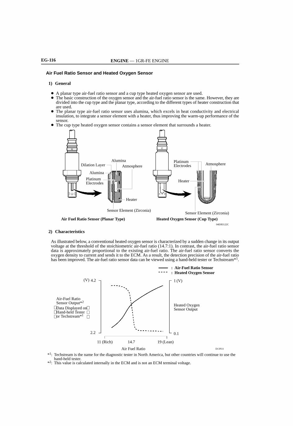
Air Fuel Ratio Sensor and Heated Oxygen Sensor
1) General
A planar type air-fuel ratio sensor and a cup type heated oxygen sensor are used. The basic construction of the oxygen sensor and the air-fuel ratio sensor is the same. However, they are
divided into the cup type and the planar type, according to the different types of heater construction thatare used.
The planar type air-fuel ratio sensor uses alumina, which excels in heat conductivity and electricalinsulation, to integrate a sensor element with a heater, thus improving the warm-up performance of thesensor.
The cup type heated oxygen sensor contains a sensor element that surrounds a heater.
04E0EG22C
Atmosphere
Heater
PlatinumElectrodes
Air Fuel Ratio Sensor (Planar Type)
Sensor Element (Zirconia)
Heater
AtmosphereAlumina
PlatinumElectrodes
Alumina
Dilation Layer
Heated Oxygen Sensor (Cup Type)
Sensor Element (Zirconia)
2) Characteristics
As illustrated below, a conventional heated oxygen sensor is characterized by a sudden change in its outputvoltage at the threshold of the stoichiometric air-fuel ratio (14.7:1). In contrast, the air-fuel ratio sensordata is approximately proportional to the existing air-fuel ratio. The air-fuel ratio sensor converts theoxygen density to current and sends it to the ECM. As a result, the detection precision of the air-fuel ratiohas been improved. The air-fuel ratio sensor data can be viewed using a hand-held tester or Techstream*1.
D13N11
Air-Fuel Ratio Sensor Output*2 Heated Oxygen
Sensor Output
: Air-Fuel Ratio Sensor: Heated Oxygen Sensor
Air Fuel Ratio
11 (Rich) 14.7 19 (Lean)
0.1
1
2.2
4.2(V) (V)
*1: Techstream is the name for the diagnostic tester in North America, but other countries will continue to use the hand-held tester.
*2: This value is calculated internally in the ECM and is not an ECM terminal voltage.
Data Displayed on Hand-held Tester or Techstream*1

ENGINE — 1GR-FE ENGINE EG-117
9. Construction
The configuration of the engine control system is as shown in the following chart.
04E0EG12C
VG SFI
SENSORS
MASS AIR FLOW METER
ACTUATORS
#10
(Continued)
AIR PRESSURE SENSOR (For Bank 1)
COMBINATION METER
STOP LIGHT SWITCH
VVT SENSORS
KNOCK SENSORS
THROTTLE POSITION SENSOR
ACCELERATOR PEDAL POSITION SENSOR
ENGINE COOLANTTEMP. SENSOR
CRANKSHAFT POSITION SENSOR
INTAKE AIR TEMP. SENSOR
AIRBAG SENSOR ASSEMBLY
AIR PRESSURE SENSOR (For Bank 2)
VPA
THW
NE
THA
VPA2
VTA1VTA2
KNK1KNK2
VV1VV2
AIP2
AIP
SPD
STP
CAN
ECM
#50
#40
#30
#20
#60
IGT1 toIGT6
IGF1
M
FPC
FC
ACIS
OC2
OC1
No.1 INJECTOR
ESA
VVT-i
THROTTLE CONTROL MOTOR
ETCS-i
SPARK PLUGS
IGNITION COIL with IGNITER
FUEL PUMP CONTROL
VSV
ACIS
CAMSHAFT TIMING OILCONTROL VALVE LH
CAMSHAFT TIMING OILCONTROL VALVE RH
FUEL PUMP ECU
CIRCUIT OPENING RELAY
No.6 INJECTOR
No.5 INJECTOR
No.4 INJECTOR
No.3 INJECTOR
No.2 INJECTOR
FUEL PUMP
D1
• Vehicle Speed Signal

ENGINE — 1GR-FE ENGINEEG-118
04E0EG13C
HT2B
(Continued)
ECM
(Bank 2, Sensor 1)
(Bank 2, Sensor 2)
(Bank 1, Sensor 2)
(Bank 1, Sensor 1)
A/F SENSOR HEATER
OXYGEN SENSOR HEATER
A/F SENSOR & OXYGEN SENSORHEATER CONTROL
STARTER RELAY
PARK/NEUTRAL POSITIONSWITCH
ACC CUT RELAY
STARTER CONTROL
ELECTRIC AIR PUMP (Bank 2)
AIR INJECTION CONTROLVALVE (Bank 2)
AIR INJECTION CONTROLDRIVER (Bank 2)
ELECTRIC AIR PUMP (Bank 1)
AIR INJECTION CONTROLVALVE (Bank 1)
AIR INJECTION CONTROLDRIVER (Bank 1)
AIR INJECTION CONTROL
AIR CONDITIONING AMPLIFIER
POWER STEERING OIL PRESSURE SWITCH
GENERATOR
PRESSURE SENSOR
PUMP MODULE
(Bank 2, Sensor 2)
(Bank 1, Sensor 2)
HEATED OXYGEN SENSOR
(Bank 2, Sensor 1)
(Bank 1, Sensor 1)
AIR FUEL RATIO SENSOR
TRANSMISSION CONTROL SWITCH
• Neutral Start Signal• Shift Lever Position Signal
PARK/NEUTRAL POSITION SWITCH
• Starter Signal• Ignition Signal
IGNITION SWITCH
HT1B
HA2A
HA1A
STA
STAR
ACCR
AID2
ARV2
ARP2
AIDI
AIRV
AIRP
STSW
NSWR, D, N, P
S
SFTD
SFTU
OX2B
OX1B
A2A+
A1A+
PPMP
ALT
PSW
AC1
ACT
IGSW
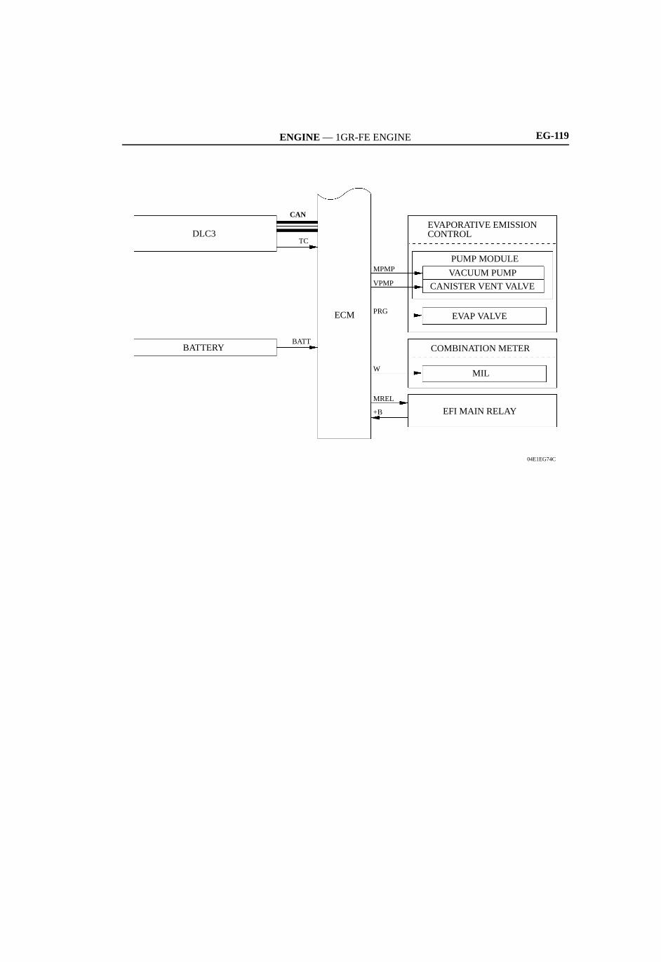
ENGINE — 1GR-FE ENGINE EG-119
04E1EG74C
ECM
EFI MAIN RELAY
MIL
COMBINATION METER
EVAP VALVE
CANISTER VENT VALVE
VACUUM PUMP
PUMP MODULE
EVAPORATIVE EMISSION CONTROL
BATTERY
DLC3
MPMP
VPMP
PRG
CAN
MREL
TC
+B
BATT
W

ENGINE — 1GR-FE ENGINE EG-99
5. ETCS-i (Electronic Throttle Control System-intelligent)
General
ETCS-i uses the ECM to calculate the optimal throttle valve angle that is appropriate for the respectivedriving condition and uses a throttle control motor to control the angle.The ETCS-i consists of the following five functions: Normal Throttle Control (non-linear control) ISC (Idle Speed Control) TRAC (Traction Control) or AUTO LSD VSC (Vehicle Stability Control) Coordination Control Cruise Control
System Diagram
279EG19
Fuel Injection
Ignition Coils
CAN
ECM
Skid Control ECU
Junction Connector
Cruise Control Switch
Mass Air Flow Meter
Throttle Control Motor
Throttle Position Sensor
Throttle ValveAccelerator Pedal Position Sensor

ENGINE — 1GR-FE ENGINEEG-100
Normal Throttle Control (Non-linear Control)
Controls the throttle to an optimal throttle valve angle that is appropriate for the driving condition basedon information such as the amount of the accelerator pedal effort and the engine speed in order to realizeexcellent throttle control and comfort in all operating ranges.
Control examples during Acceleration and Deceleration
150EG37
Vehicle’s Longitudinal G
Throttle Valve Angle
Time
Ignition Timing
: With Control: Without Control
0
0
0
Idle Speed Control
The ECM controls the throttle valve in order to constantly maintain an ideal idle speed.
TRAC or AUTO LSD
As part of the TRAC or AUTO LSD the throttle valve opening is reduced by a demand signal sent from theSkid Control ECU to the ECM. This demand signal will be sent if an excessive amount of slippage occursat a drive wheel, thus facilitating vehicle stability and the application of an appropriate amount of powerto the road.
VSC Coordination Control
In order to bring the effectiveness of the VSC system control into full play, the throttle valve angle iscontrolled by effecting a coordination control with the Skid Control ECU.
Cruise Control
The ECM directly actuates the throttle valve for operation of the cruise control.

ENGINE — 1GR-FE ENGINEEG-124
12. Cranking Hold Function
General
Once the ignition switch is turned to the START position, this function operates the starter until the enginestarts, without having to hold the ignition switch in the START position. This prevents application of thestarter for an inadequate length of time and it also prevents the engine from being cranked after it hasstarted.
When the ECM detects a start signal from the ignition switch, it monitors engine speed (NE) and operatesthe starter until it determines that the engine has started. If the engine has already started, the ECM willnot operate the starter, even if the ECM receives a start signal from the ignition switch.
System Diagram
04E0EG21C
ACC
Ignition SwitchACC Cut Relay
• Engine Speed Signal• Engine Coolant Temp. Signal
ECM
Park/Neutral Position Switch
Starter Relay
Starter
Battery
ST2

ENGINE — 1GR-FE ENGINE EG-125
Operation
As indicated in the timing chart shown below, when the ECM detects a start signal from the ignitionswitch, the ECM outputs a starter relay drive signal (STAR) that flows through the park/neutral positionswitch to turn on the starter relay. As a result, the starter operates. (If the engine is already running, theECM will not turn on the starter relay.)
After the engine speed rises above approximately 500 rpm, the ECM determines that the engine hasstarted and stops the output of the starter relay drive signal (STAR) to stop the operation of the starter.
The ECM outputs an ACC cut relay drive signal (ACCR) to turn on the ACC cut relay, in order to preventaccessory light flickering from occurring while cranking.
If the engine fails to start, the starter operates as long as its maximum continuous operation time and stopsautomatically. The maximum continuous operation time is approximately 2 seconds through 25 secondsdepending on the engine coolant temperature. When the engine coolant temperature is extremely low,maximum cranking time is approximately 25 seconds. When the engine is warmed up sufficiently,maximum cranking time is approximately 2 seconds.
This system has following safety features:- While the engine is running, the starter cannot operate.- The starter will stop operating once the engine has started, even if the ignition switch stays in the START
position.- Starter operation is limited to a maximum of 30 seconds to protect the starter motor.- The starter will stop if the ECM cannot detect an engine speed signal (NE) while the starter is operating.
Timing Chart
230LX17
ECM determines that the engine has startedsuccessfully when the engine speed isapproximately 500 rpm.
Failed Starting of Engine
SuccessfulStarting of Engine
Cranking LimitApprox. 2 to 25 sec.
Engine SpeedSignal (NE)
ACC Cut Relay
Starter Relay
OFF
ON
Ignition Switch (Start Signal)
OFF
ON
OFF
ON
ENGINE — 1GR-FE ENGINE EG-101
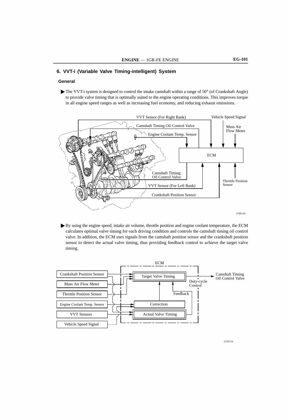
6. VVT-i (Variable Valve Timing-intelligent) System
General
The VVT-i system is designed to control the intake camshaft within a range of 50° (of Crankshaft Angle)to provide valve timing that is optimally suited to the engine operating conditions. This improves torquein all engine speed ranges as well as increasing fuel economy, and reducing exhaust emissions.
279EG20
Throttle Position Sensor
Mass Air Flow Meter
Vehicle Speed Signal
ECM
Crankshaft Position Sensor
VVT Sensor (For Left Bank)
Camshaft Timing Oil Control Valve
Engine Coolant Temp. Sensor
Camshaft Timing Oil Control Valve
VVT Sensor (For Right Bank)
By using the engine speed, intake air volume, throttle position and engine coolant temperature, the ECMcalculates optimal valve timing for each driving condition and controls the camshaft timing oil controlvalve. In addition, the ECM uses signals from the camshaft position sensor and the crankshaft positionsensor to detect the actual valve timing, thus providing feedback control to achieve the target valvetiming.
221EG16
Camshaft Timing Oil Control Valve
Engine Coolant Temp. Sensor
VVT Sensors
Vehicle Speed Signal
Crankshaft Position Sensor
Mass Air Flow Meter
Throttle Position Sensor
Correction
Actual Valve Timing
ECM
Target Valve Timing
Feedback
Duty-cycleControl

ENGINE — 1GR-FE ENGINE
To AdvanceSide
To AdvanceSide
To Retard Side
Latest Timing
EX
TDC
IN
BDC
EX
EX
EX
IN
IN
IN
TDC
BDC
EG-102
Effectiveness of the VVT-i System
Operation State Objective Effect
During Idle
188EG51
Eliminating overlap reducesblow back to the intake side.
• Stabilized idling rpm• Better fuel economy
At Light Load
188EG64
Minimizing overlap reducesblow back to the intake side.
Ensured engine stability
At Medium Load
188EG65
Increasing overlap increasesinternal EGR, reducingpumping losses.
• Better fuel economy• Improved emission
control
In Low to MediumSpeed Range withHeavy Load
188EG66
Advancing the intake valveclosing timing allows forvolumetric efficiencyimprovement.
Improved torque in lowto medium speed range
(Continued)

ENGINE — 1GR-FE ENGINE
Latest Timing
Latest Timing
To Retard Side
EX IN
INEX
EX IN
EG-103
Operation State Objective Effect
In High Speed Rangewith Heavy Load
188EG67
Retarding the intake valveclosing timing allows forvolumetric efficiencyimprovement.
Improved output
At Low Temperatures
188EG53
Eliminating overlap preventsblow back to the intake sideand stabilizes the idling speedat fast idle.
• Stabilized fast idlingrpm
• Better fuel economy
• Upon Starting• Stopping the Engine
188EG53
Eliminating overlap reducesblow back to the intake side.
Improved startability

ENGINE — 1GR-FE ENGINEEG-104
Construction
1) VVT-i Controller
The VVT-i controller consists of an outer housing that is driven by the timing chain sprocket, and a vanesubassembly that is coupled to intake camshaft. The oil pressure sent from the advance or retard side passage of the intake camshaft causes rotation of
the VVT-i controller vane subassembly relative to the timing chain sprocket to vary the valve timingcontinuously (steplessly).
When the engine stops, the VVT-i controller is locked to the most retarded angle by its lock pin. Thisensures engine stability.
279EG21At a StopIn Operation
Oil Pressure
Timing Chain Sprocket
Intake Camshaft
Lock PinOuter Housing
Timing Rotor
2) Camshaft Timing Oil Control Valve
The camshaft timing oil control valve controls its spool valve using duty-cycle control from the ECM. Thisallows hydraulic pressure to be applied to the VVT-i controller advance or retard side. When the engineis stopped, the camshaft timing oil control valve will move to the most retarded state.
238EG62
CoilPlunger
Oil Pressure
DrainDrain
Spool ValveSleeve
Spring
To VVT-i Controller (Retard Side)
To VVT-i Controller(Advance Side)

ENGINE — 1GR-FE ENGINE EG-105
Operation
1) Advance
When the camshaft timing oil control valve is positioned as illustrated below by the advance signals fromthe ECM, the resultant oil pressure is applied to the timing advance side vane chamber to rotate thecamshaft in the timing advance direction.
238EG63
Rotation DirectionOil Pressure
Vane
ECM
DrainIN
2) Retard
When the camshaft timing oil control valve is positioned as illustrated below by the retard signals fromthe ECM, the resultant oil pressure is applied to the timing retard side vane chamber to rotate the camshaftin the timing retard direction.
238EG64
Rotation Direction
Oil Pressure
Vane
ECM
Drain IN
3) Hold
After reaching the target timing, the engine valve timing is maintained by keeping the camshaft timingoil control valve in the neutral position unless the engine operating conditions change.This maintains the engine valve timing at the desired target position by preventing the engine oil fromrunning out of the oil control valve.

ENGINE — 1GR-FE ENGINEEG-106
7. Layout of Main Components
04E0EG15Z
Accelerator Pedal Position Sensor
DLC3
Malfunction Indicator Lamp
Air Fuel Ratio Sensor (Bank 2, Sensor 1)
Heated Oxygen Sensor (Bank 2, Sensor 2)
Fuel PumpFuel Pump ECU
Pump Module• Vacuum Pump• Pressure Sensor• Canister Vent Valve
Charcoal Canister
Air Fuel Ratio Sensor (Bank 1, Sensor 1)
Heated Oxygen Sensor (Bank 1, Sensor 2)
04E0EG16Z
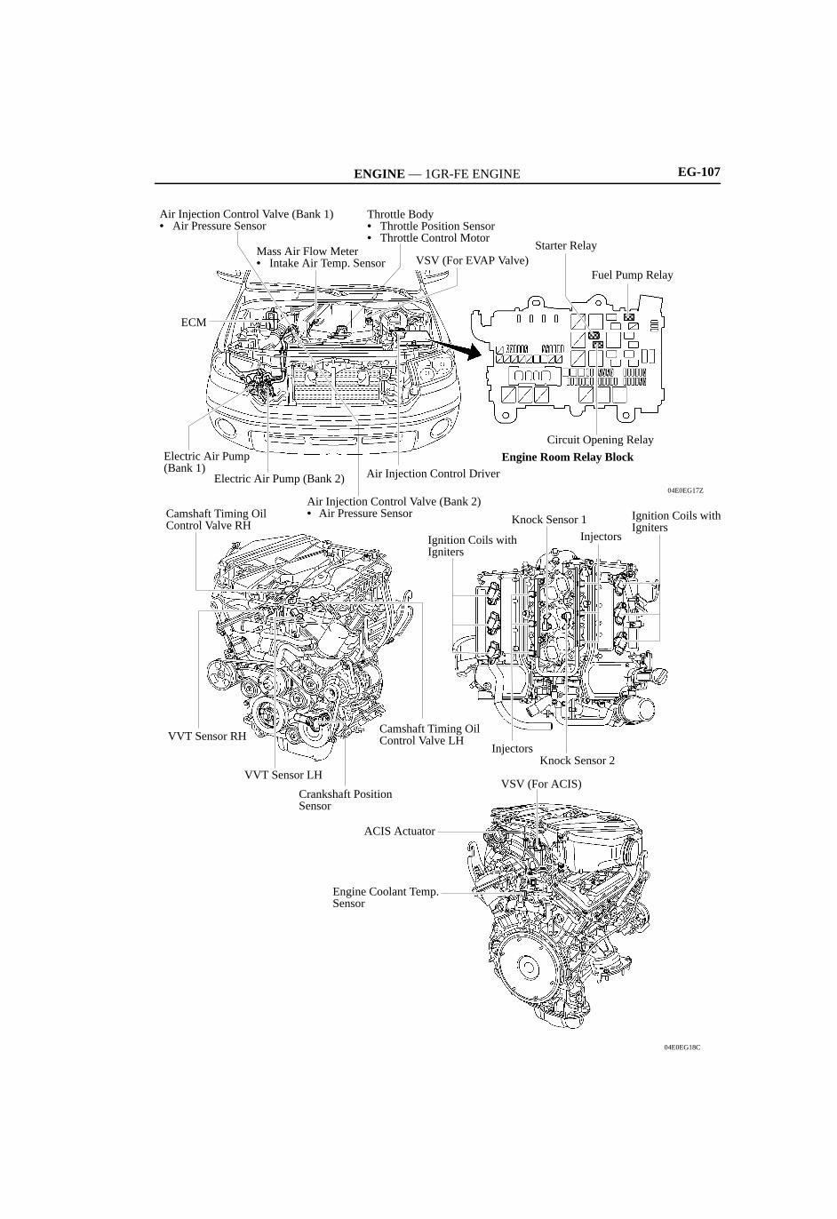
ENGINE — 1GR-FE ENGINE EG-107
04E0EG17Z
Camshaft Timing Oil Control Valve LH
Air Injection Control Valve (Bank 2)• Air Pressure Sensor
Electric Air Pump (Bank 1)
ECM
Electric Air Pump (Bank 2) Air Injection Control Driver
Starter Relay
04E0EG18C
Engine Coolant Temp. Sensor
ACIS Actuator
VSV (For ACIS)
Knock Sensor 2Injectors
Ignition Coils withIgniters
Injectors
Knock Sensor 1
Ignition Coils with Igniters
Crankshaft Position Sensor
VVT Sensor LH
VVT Sensor RH
Camshaft Timing Oil Control Valve RH
Engine Room Relay Block
Circuit Opening Relay
Fuel Pump RelayVSV (For EVAP Valve)
Throttle Body• Throttle Position Sensor• Throttle Control Motor
Air Injection Control Valve (Bank 1)• Air Pressure Sensor
Mass Air Flow Meter• Intake Air Temp. Sensor

ENGINE — 1GR-FE ENGINEEG-138
14. ACIS (Acoustic Control Induction System)
General
The ACIS uses the intake air control valve as a bulkhead to divide the intake manifold into 2 stages. Theintake air control valve is opened and closed to vary the effective length of the intake manifold in accordancewith engine speed and throttle valve opening angle.This increases the power output in all ranges from low to high engine speeds.
System Diagram
0240EG25CThrottle Position Sensor
Crankshaft Position Sensor
ECM
VSV (For ACIS)
Vacuum Tank
Intake Air Control ValveACIS Actuator
ENGINE — 1GR-FE ENGINE EG-139
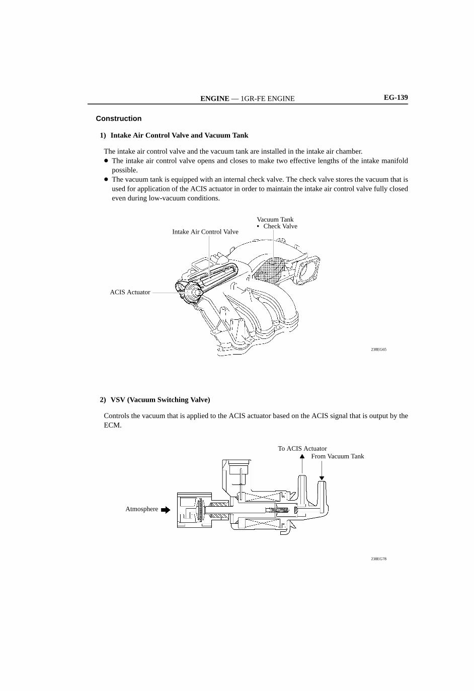
Construction
1) Intake Air Control Valve and Vacuum Tank
The intake air control valve and the vacuum tank are installed in the intake air chamber. The intake air control valve opens and closes to make two effective lengths of the intake manifold
possible. The vacuum tank is equipped with an internal check valve. The check valve stores the vacuum that is
used for application of the ACIS actuator in order to maintain the intake air control valve fully closedeven during low-vacuum conditions.
238EG65
Vacuum Tank• Check Valve
Intake Air Control Valve
ACIS Actuator
2) VSV (Vacuum Switching Valve)
Controls the vacuum that is applied to the ACIS actuator based on the ACIS signal that is output by theECM.
238EG78
From Vacuum TankTo ACIS Actuator
Atmosphere
ENGINE — 1GR-FE ENGINEEG-140
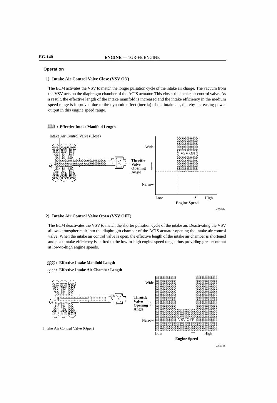
Operation
1) Intake Air Control Valve Close (VSV ON)
The ECM activates the VSV to match the longer pulsation cycle of the intake air charge. The vacuum fromthe VSV acts on the diaphragm chamber of the ACIS actuator. This closes the intake air control valve. Asa result, the effective length of the intake manifold is increased and the intake efficiency in the mediumspeed range is improved due to the dynamic effect (inertia) of the intake air, thereby increasing poweroutput in this engine speed range.
279EG22
VSV ON
HighEngine Speed
Low
Narrow
Throttle Valve OpeningAngle
Wide
Intake Air Control Valve (Close)
: Effective Intake Manifold Length
2) Intake Air Control Valve Open (VSV OFF)
The ECM deactivates the VSV to match the shorter pulsation cycle of the intake air. Deactivating the VSVallows atmospheric air into the diaphragm chamber of the ACIS actuator opening the intake air controlvalve. When the intake air control valve is open, the effective length of the intake air chamber is shortenedand peak intake efficiency is shifted to the low-to-high engine speed range, thus providing greater outputat low-to-high engine speeds.
279EG23
Intake Air Control Valve (Open)
VSV OFF
HighEngine Speed
Low
Narrow
Throttle Valve OpeningAngle
Wide
: Effective Intake Manifold Length
: Effective Intake Air Chamber Length

ENGINE — 1GR-FE ENGINE
Typical Enabling Condition
Service Tip
EG-126
13. Evaporative Emission Control System
General
The evaporative emission control system prevents the fuel vapor that is created in the fuel tank from beingreleased directly into the atmosphere. The charcoal canister stores the fuel vapor that has been created in the fuel tank. The ECM controls the EVAP valve in accordance with the driving conditions in order to direct the fuel
vapor into the engine, where it is burned. Using this system, the ECM checks for evaporative emission leaks and stores DTCs (Diagnostic Trouble
Codes) in the event of a malfunction. An evaporative emission leak check consists of an application ofa vacuum to the evaporative emission system and monitoring the system for changes in pressure in orderto detect a leak.
This system consists of an EVAP valve, charcoal canister, refueling valve, pump module, and ECM. An ORVR (Onboard Refueling Vapor Recovery) function is provided in the refueling valve. The pressure sensor has been integrated with the pump module. An air filter has been provided on the fresh air line. This air filter is maintenance-free. An EVAP service port is not used. The following are typical conditions that enable an evaporative emission leak check:
Five hours have elapsed after the engine has been turned OFF*. Altitude: Below 2400 m (8000 feet) Battery Voltage: 10.5 V or more Ignition switch: OFF Engine Coolant Temperature: 4.4 to 35°C (40 to 95°F) Intake Air Temperature: 4.4 to 35°C (40 to 95°F)
*: If engine coolant temperature does not drop below 35°C (95°F), this time is extended to 7 hours. Evenafter that, if the temperature is not less than 35°C (95°F), the time is extended to 9.5 hours.
The pump module performs a fuel evaporative emission leakage check. This check is doneapproximately 5 hours after the engine is turned off. Sound may be heard coming from underneath thevehicle near the fuel tank for several minutes. This does not indicate a malfunction. A pinpoint pressure test procedure is adopted by pressurizing the fresh air line that runs from the pump
module to the air filler neck. For details, see the 2007 TOYOTA TUNDRA Repair Manual (Pub. No.RM04E2U).

ENGINE — 1GR-FE ENGINE EG-127
System Diagram
060XA15C
Refueling Valve
Pump Module
Air Filter
ECM
Fuel Tank
EVAP Valve
Fresh Air Line
Purge Air Line
To Intake Manifold
Pressure Sensor
Vacuum Pump & Pump Motor
Canister Vent Valve
Restrictor Passage
M
P
CharcoalCanister
Layout of Main Components
04E0EG20Z
Air Filter
Charcoal Canister
Pump Module• Pressure Sensor• Canister Vent Valve• Vacuum Pump & Pump Motor
Fuel Tank
Front

ENGINE — 1GR-FE ENGINEEG-128
Function of Main Components
Component Function
Charcoal Canister Contains activated charcoal to absorb the fuel vapor that is created in thefuel tank.
Refueling
Controls the flow rate of the fuel vapor from the fuel tank to the charcoalcanister when the system is purging or during refueling.Refueling
ValveRestrictor Passage Prevents a large amount of vacuum during purge operation or system
monitoring operation from affecting the pressure in the fuel tank.
Fresh Air Line Fresh air goes into the charcoal canister and the cleaned drain air goes outinto the atmosphere.
Canister VentValve
Opens and closes the fresh air line in accordance with the signals from theECM.
Pump ModuleVacuum Pump& Pump Motor
Applies vacuum to the evaporative emission system in accordance with thesignals from the ECM.
Pressure Sensor Detects the pressure in the evaporative emission system and sends thesignals to the ECM.
EVAP Valve
Opens in accordance with the signals from the ECM when the system ispurging, in order to send the fuel vapor that was absorbed by the charcoalcanister into the intake manifold. In system monitoring mode, this valvecontrols the introduction of the vacuum into the fuel tank.
Air Filter Prevents dust and debris in the fresh air from entering the system.
ECM
Controls the pump module and the EVAP valve in accordance with thesignals from various sensors, in order to achieve a purge volume that suitsthe driving conditions. In addition, the ECM monitors the system for anyleakage and stores a DTC if a malfunction is found.

ENGINE — 1GR-FE ENGINE EG-129
Construction and Operation
1) Refueling Valve
The refueling valve consists of chamber A, chamber B, and a restrictor passage. A constant atmosphericpressure is applied to chamber A. During refueling, the internal pressure of the fuel tank increases. This pressure causes the refueling
valve to lift up, allowing the fuel vapors to enter the charcoal canister. The restrictor passage prevents the large amount of vacuum that is created during purge operation or
system monitoring operation from entering the fuel tank, and limits the flow of the fuel vapor from thefuel tank to the charcoal canister. If a large volume of fuel vapor enters the intake manifold, it will affectthe air-fuel ratio control of the engine. Therefore, the role of the restrictor passage is to help preventthis from occurring.
030LS05CDuring Refueling
Negative Pressure(Intake Manifold Pressure)
Positive Pressure(Fuel Tank Pressure)
To Fuel Tank
Charcoal Canister
Restrictor Passage
Internal Pressure
Chamber B
From Fuel Tank
Refueling Valve (Open)
Chamber A
Fresh Air Line
During Purge Operation or System Monitoring Operation
2) Fuel Inlet (Fresh Air Inlet)
This evaporative emission control system has its fresh air line inlet located near the fuel inlet. The freshair from the atmosphere and drain air cleaned by the charcoal canister will go in and out of the systemthrough the passage shown below.
228TU119
Fuel Tank Cap Fresh Air
Fuel Inlet PipeCleaned Drain Air
To Charcoal Canister
ENGINE — 1GR-FE ENGINEEG-130
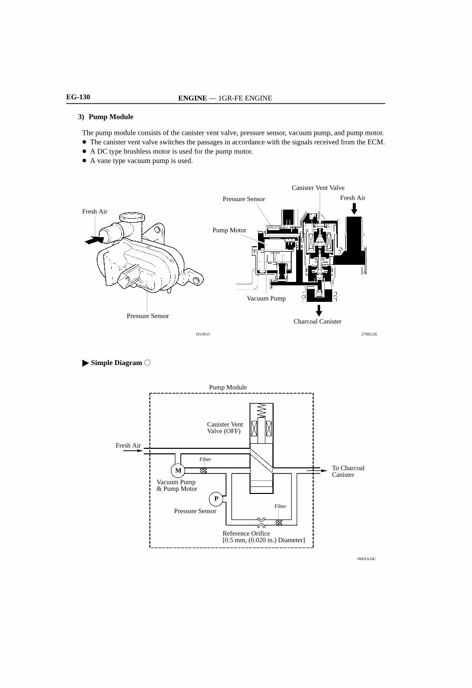
3) Pump Module
The pump module consists of the canister vent valve, pressure sensor, vacuum pump, and pump motor. The canister vent valve switches the passages in accordance with the signals received from the ECM. A DC type brushless motor is used for the pump motor. A vane type vacuum pump is used.
279EG26
Pressure Sensor
Fresh Air
D13N15
Charcoal Canister
Fresh Air
Canister Vent Valve
Pressure Sensor
Pump Motor
Vacuum Pump
Simple Diagram
060XA16C
To Charcoal Canister
Canister Vent Valve (OFF)
Pump Module
Pressure Sensor
Fresh Air
M
Vacuum Pump & Pump Motor
Filter
Reference Orifice [0.5 mm, (0.020 in.) Diameter]
Filter
P

ENGINE — 1GR-FE ENGINE EG-131
System Operation
1) Purge Flow Control
When the engine has reached a predetermined state (closed loop, engine coolant temp. above 80°C(176°F), etc.), stored fuel vapor is purged from the charcoal canister whenever the EVAP valve is openedby the ECM.The ECM will change the duty ratio cycle of the EVAP valve, thus controlling purge flow volume. Purgeflow volume is determined by intake manifold pressure and the duty ratio cycle of the EVAP valve.Atmospheric pressure is allowed into the charcoal canister to ensure that purge flow is constantlymaintained whenever purge vacuum is applied to the charcoal canister.
060XA17C
To Intake Manifold
EVAP Valve (Open)
Atmosphere
ECM
2) ORVR (Onboard Refueling Vapor Recovery)
When the internal pressure of the fuel tank increases during refueling, this pressure causes the diaphragmin the refueling valve to lift up. This allows the fuel vapor to enter the charcoal canister. The air that hasbeen cleaned through the charcoal canister is discharged outside the vehicle via the fresh air line becausethe canister vent valve is always open when the system is in a mode other than the monitoring mode (evenwhen the engine is stopped). If the vehicle is refueled in system monitoring mode, the ECM will recognizethe refueling by way of the pressure sensor, which detects the sudden pressure increase in the fuel tank,and will open the canister vent valve.
060XA18C
Close
Open

ENGINE — 1GR-FE ENGINEEG-132
3) EVAP Leak Check
a. General
The EVAP leak check operates in accordance with the following timing chart:
Timing Chart
060XA19C
EVAP Valve
Canister Vent Valve
Pump Motor
System Pressure
ON (Open)
OFF (Closed)
OFF (Vent)
ON
OFF
Atmospheric Pressure
0.02 in. Pressure
1) 2) 3) 4) 5) 6)
ON
Order Operation Description Time
1) Atmospheric PressureMeasurement
The ECM turns the canister vent valve OFF (vent) andmeasures EVAP system pressure to determine the atmosphericpressure.
—
2) 0.02 in. Leak PressureMeasurement
The vacuum pump creates negative pressure (vacuum), whichis limited by a 0.02 in. orifice. The pressure is measured, andthe ECM determines this as the 0.02 in. leak pressure.
20 sec.
3) EVAP Leak Check
The vacuum pump creates negative pressure (vacuum) in theEVAP system and EVAP system pressure is measured. If thepressure after stabilization is greater than the 0.02 in. leakpressure, the ECM determines that the EVAP system has a leak.If EVAP pressure does not stabilize within 15 minutes, ECMcancels EVAP monitor.
Within 15 min.
4) EVAP Valve MonitorThe ECM opens the EVAP valve and measures the EVAPpressure increase. If the increase is large, the ECM interpretsthis as normal.
10 sec.
5) Repeat 0.02 in. LeakPressure Measurement
The vacuum pump creates negative pressure (vacuum) thatpasses through the 0.02 in. orifice and pressure is measured.The ECM determines this as the 0.02 in. leak pressure.
20 sec.
6) Final Check The ECM measures atmospheric pressure and records theresult of the monitor operation.
—

ENGINE — 1GR-FE ENGINE EG-133
b. Atmospheric Pressure Measurement
1) When the ignition switch is turned OFF, the EVAP valve and the canister vent valve are turned OFF.Therefore, atmospheric pressure is introduced into the charcoal canister.
2) The ECM records the atmospheric pressure measured by the pressure sensor.3) If the measurement value is out of range, the ECM actuates the vacuum pump in order to monitor the
changes in the pressure.
060XA20C
Pump Module
Vacuum Pump & Pump Motor
Pressure Sensor
EVAP Valve (OFF)
Atmosphere
ECM
Canister Vent Valve (OFF)
M
P
D13N22
ON (Open)
OFF (Closed)
OFF (Vent)
ON
OFF
Atmospheric Pressure
Atmospheric Pressure Measurement
ON
0.02 in. Pressure
EVAP Valve
Canister Vent Valve
Pump Motor
System Pressure
ENGINE — 1GR-FE ENGINEEG-134
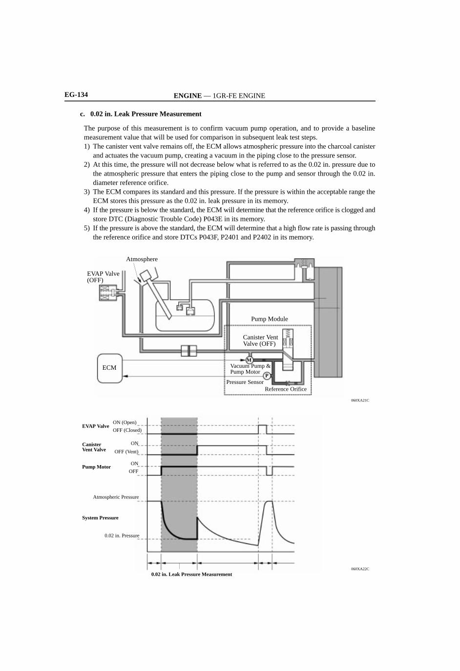
c. 0.02 in. Leak Pressure Measurement
The purpose of this measurement is to confirm vacuum pump operation, and to provide a baselinemeasurement value that will be used for comparison in subsequent leak test steps.1) The canister vent valve remains off, the ECM allows atmospheric pressure into the charcoal canister
and actuates the vacuum pump, creating a vacuum in the piping close to the pressure sensor.2) At this time, the pressure will not decrease below what is referred to as the 0.02 in. pressure due to
the atmospheric pressure that enters the piping close to the pump and sensor through the 0.02 in.diameter reference orifice.
3) The ECM compares its standard and this pressure. If the pressure is within the acceptable range theECM stores this pressure as the 0.02 in. leak pressure in its memory.
4) If the pressure is below the standard, the ECM will determine that the reference orifice is clogged andstore DTC (Diagnostic Trouble Code) P043E in its memory.
5) If the pressure is above the standard, the ECM will determine that a high flow rate is passing throughthe reference orifice and store DTCs P043F, P2401 and P2402 in its memory.
060XA21C
Pump Module
Vacuum Pump & Pump Motor
Pressure Sensor
EVAP Valve (OFF)
Atmosphere
ECM
Canister Vent Valve (OFF)
M
P
Reference Orifice
060XA22C
ON (Open)
OFF (Closed)
OFF (Vent)
ON
OFF
Atmospheric Pressure
0.02 in. Pressure
0.02 in. Leak Pressure Measurement
ON
EVAP Valve
Canister Vent Valve
Pump Motor
System Pressure

ENGINE — 1GR-FE ENGINE EG-135
d. EVAP Leak Check
1) While actuating the vacuum pump, the ECM turns the canister vent valve on in order to introduce avacuum into the charcoal canister.
2) When the pressure in the system stabilizes, the ECM compares this pressure and the 0.02 in. pressurein order to determine if leakage is occurring.
3) If the detected value is below the 0.02 in. pressure, the ECM determines that a leak is not occurring.4) If the detected value is above the 0.02 in. pressure and near atmospheric pressure, the ECM determines
that there is a gross leak (large hole) and stores DTC P0455 in its memory.5) If the detected value is above the 0.02 in. pressure, the ECM determines that there is a small leak
(minor leakage) and stores DTC P0456 in its memory.
060XA23C
Pump Module
Vacuum Pump & Pump Motor
Pressure Sensor
EVAP Valve (OFF)
Atmosphere
ECM
Canister Vent Valve (ON)
Reference Orifice
M
P
Vacuum
060XA24C
P0455
EVAP ValveON (Open)
OFF (Closed)
OFF (Vent)
ON
OFF
Atmospheric Pressure
0.02 in. Pressure
EVAP Leak Check
P0456
Normal
ONCanister Vent Valve
Pump Motor
System Pressure
ENGINE — 1GR-FE ENGINEEG-136
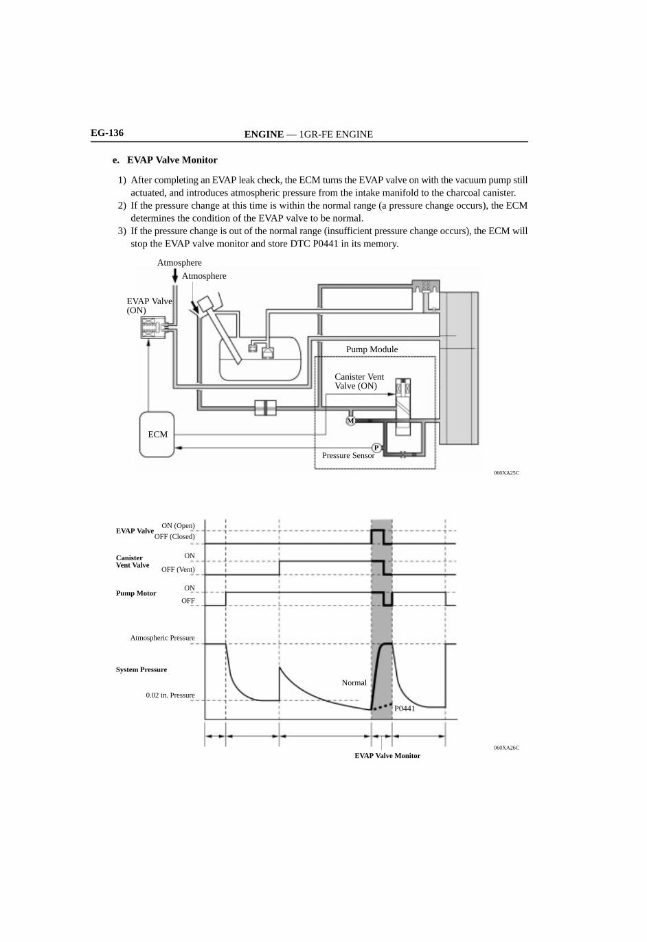
e. EVAP Valve Monitor
1) After completing an EVAP leak check, the ECM turns the EVAP valve on with the vacuum pump stillactuated, and introduces atmospheric pressure from the intake manifold to the charcoal canister.
2) If the pressure change at this time is within the normal range (a pressure change occurs), the ECMdetermines the condition of the EVAP valve to be normal.
3) If the pressure change is out of the normal range (insufficient pressure change occurs), the ECM willstop the EVAP valve monitor and store DTC P0441 in its memory.
060XA25C
Pump Module
Pressure Sensor
EVAP Valve (ON)
Atmosphere
ECM
Canister Vent Valve (ON)
M
P
Atmosphere
060XA26C
ON (Open)
OFF (Closed)
OFF (Vent)
ON
OFF
Atmospheric Pressure
0.02 in. Pressure
EVAP Valve Monitor
P0441
Normal
ON
EVAP Valve
Canister Vent Valve
Pump Motor
System Pressure

ENGINE — 1GR-FE ENGINE EG-137
f. Repeat 0.02 in. Leak Pressure Measurement
1) While the ECM operates the vacuum pump, the EVAP valve and canister vent valve are turned offand a repeat 0.02 in. leak pressure measurement is performed.
2) The ECM compares the measured pressure with the pressure during the EVAP leak check.3) If the pressure during the EVAP leak check is below the measured value, the ECM determines that
there is no leakage.4) If the pressure during the EVAP leak check is above the measured value, the ECM determines that
there is a small leak and stores DTC P0456 in its memory.
060XA27C
Pump Module
Vacuum Pump & Pump Motor
Pressure Sensor
EVAP Valve (OFF)
Atmosphere
ECM
Canister Vent Valve (OFF)
Reference Orifice
M
P
060XA28C
ON (Open)
OFF (Closed)
OFF (Vent)
ON
OFF
Atmospheric Pressure
0.02 in. Pressure
Repeat 0.02 in. Leak Pressure Measurement
P0456
Normal
ON
EVAP Valve
Canister Vent Valve
Pump Motor
System Pressure

ENGINE — 1GR-FE ENGINE
Service Tip
EG-143
4. Diagnosis
When the ECM detects a malfunction, the ECM records the fault and memorizes the information thatrelates to the fault. Furthermore, it illuminates or blinks the MIL (Malfunction Indicator Lamp) in thecombination meter to inform the driver.
The ECM will also store the DTCs (Diagnostic Trouble Codes) of the malfunctions. The DTCs can beaccessed using the hand-held tester or Techstream*.
For details, see the 2007 TOYOTA TUNDRA Repair Manual (Pub. No. RM04E2U).
The ECM uses the CAN protocol for diagnostic communication. Therefore, a hand-held tester orTechstream* and a dedicated adapter [CAN VIM (Vehicle Interface Module)] are required foraccessing diagnostic data.
To clear a DTC that is stored in the ECM, use a hand-held tester or Techstream*, disconnect the batteryterminal or remove the EFI fuse for 1 minute or longer.
For details, see the 2007 TOYOTA TUNDRA Repair Manual (Pub. No. RM04E2U).
*: Techstream is the name for the diagnostic tester in North America, but other countries will continue to usethe hand-held tester.
5. Fail-Safe
General
When the ECM detects a malfunction, the ECM stops or controls the engine according to the data alreadystored in the memory.For details of the fail-safe chart, see the 2007 TOYOTA TUNDRA Repair Manual (Pub. No. RM04E2U).
Fail-safe Operation due to Accelerator Pedal Position Sensor Malfunction
The accelerator pedal position sensor contains two (Main, Sub) sensor circuits. If a malfunction occurs in either of the sensor circuits, the ECM detects the abnormal signal voltage
difference between these two sensor circuits and switches into a fail-safe mode. In this fail-safe mode,the remaining circuit is used to calculate the accelerator pedal opening, in order to operate the vehicleunder fail-safe mode control.
0240EG27C
ECM
Throttle Body
Accelerator Pedal Position Sensor
Main SubMain
Sub
OpenReturn Spring
Throttle Position Sensor
Throttle ControlMotorThrottle
Valve
M

ENGINE — 1GR-FE ENGINEEG-144
If both circuits malfunction, the ECM detects the abnormal signal voltage from these two sensor circuitsand discontinues throttle control. At this time, the vehicle can be driven using the power generated bythe engine at idle.
0240EG28C
ECM
Throttle Body
Accelerator Pedal Position Sensor
Main SubMain
Sub
CloseReturn Spring
Throttle Position Sensor
Throttle ControlMotorThrottle
Valve
M
Fail-safe Operation due to Throttle Position Sensor Malfunction
The throttle position sensor contains two (Main, Sub) sensor circuits. If a malfunction occurs in either of the sensor circuits, the ECM detects the abnormal signal voltage
difference between these two sensor circuits, cuts off the current to the throttle control motor, andswitches to a fail-safe mode.
Then, the force of the return spring causes the throttle valve to return and stay at its prescribed baseopening position. At this time, the vehicle can be driven in the fail-safe mode while the engine outputis regulated through control of the fuel injection and ignition timing in accordance with the acceleratorpedal position.
The same control as above is effected if the ECM detects a malfunction in the throttle control motor.
Ignition CoilInjectors
0240EG29C
ECM
Throttle Body
Accelerator Pedal Position Sensor
Main SubMain
Sub
OpenReturn Spring
Throttle Position Sensor
Throttle ControlMotorThrottle
Valve
M

ENGINE — 1GR-FE ENGINEEG-120
10. Fuel Pump Control
General
In this vehicle, there are 2 types of fuel pump control. The fuel pump is controlled to an optimum speed tomatch the engine operating conditions, and the fuel pump operation is cut when the SRS airbags deploy. The ECM transmits a fuel pump speed request signal to the Fuel Pump ECU that corresponds to the
engine operating conditions. The Fuel Pump ECU receives this request signal and controls the speed ofthe fuel pump in 3 stages. As a result, under light engine loads, fuel pump speed is kept low to reduceelectric power loss.
A fuel cut control is used to stop the fuel pump when any of the SRS airbags deploy. In this control, ifan airbag deployment signal from the Airbag Sensor Assembly is detected by the ECM, the ECM willturn OFF the circuit opening relay. As a result, the power supply to Fuel Pump ECU is stopped, causingthe fuel pump to stop operating. After the fuel cut control has been activated, turning the ignition switchfrom OFF to ON cancels the fuel cut control, and the engine can be restarted.
System Diagram
04E0EG23C
Fuel Pump ECU
Fuel Pump
Circuit Opening Relay
EFI RelayIgnition Switch
DiagnosisSignal
Fuel Pump OperationRequestCAN
ECMAirbag Sensor Assembly
Curtain ShieldAirbag Sensor(RH or LH)
Side & CurtainShield AirbagSensor(RH or LH)
Front Airbag Sensors(RH and LH)

ENGINE — 1GR-FE ENGINE
04E0EG25C
GND
04E0EG26C
04E0EG27C
04E0EG28C
4.1 ms
8.2 ms
12.3 ms
+B
GND
+B
GND
+B
GND
EG-121
Function of Main Component
1) Fuel Pump ECU
The Fuel Pump ECU controls fuel pump speed by receiving a duty cycle signal (FPC terminal input)from the ECM, control is performed to three stages.
The Fuel Pump ECU also detects failures in the input and output circuits at the Fuel Pump ECU andtransmits the failure status to the ECM.
04E0EG24C
FPCFPC
Duty Signal
Fuel Pump ECU
Fuel Pump
Diagnosis Signal
Fuel Pump Operation Request
ECM
DIDI
FPC Terminal Input
FPC Input Signal (Duty Signal) Fuel Pump Speed
Hi
Middle
Low
Stop

ENGINE — 1GR-FE ENGINEEG-122
11. SFI (Sequential Multiport Fuel Injection) System
This L-type SFI system directly detects the intake air mass using a hot wire type air flow meter. An independent injection system (in which fuel is injected once into each intake port for each two
revolutions of the crankshaft) is used. There are two (synchronous and non-synchronous) injections:
a) Synchronous injection, in which injection always occurs at the same timing relative to the firing order.b) The non-synchronous injection in which injection is effected regardless of the crankshaft angle.
Furthermore, to protect the engine and achieve lower fuel consumption, the system uses a fuel cutoff in whichthe injection of fuel may be stopped temporarily in accordance with the driving conditions. This system performs group injection when the engine coolant temperature is extremely low and the
engine is operating at a low speed.
208EG43
0° Crankshaft Angle
Non-synchronous InjectionIgnition
Synchronous Injection
# 10
# 20
# 30
# 40
# 50
# 60
Sequential Multiport Fuel Injection
600°480°360°240°120° 720°

ENGINE — 1GR-FE ENGINEEG-148
6. Air Injection Control System
General
To ensure the proper warm-up performance of the TWCs (Three-Way Catalytic converter) after starting acold engine, an air injection system is used. For this system, the right bank (bank 1) and left bank (bank 2) each has an electric air pump, air injection
control driver, air injection control valve, and air pressure sensor. Control of the right bank and left bankis performed independently. Two pumps are used to increase the amount of air supplied, shortening thecatalyst warm-up time.
The ECM estimates the amount of air injected to the TWCs based on signals from the mass air flow meterin order to regulate the air injection time.
Air is injected under the following conditions.
Operation Conditions
Engine Coolant Temp. 5 to 45°C (5 to 45°C)
Intake Air Temp. 5°C (41°F) or more
System Diagram
04E0EG29C
Air Injection Control Valve
Air Injection Control Driver
Electric Air Pump
Air Pressure Sensor
Intake Air Temp. Sensor
Mass Air Flow Meter
Engine Coolant Temp. Sensor
ECM
Air InjectionControl Valve
To Exhaust Manifold
Air Pressure Sensor
Diagnosis Signal
Valve Actuation Request
Pump Actuation Request
Electric Air Pump
Air
Air Injection Control Driver
Air
Right Bank (Bank 1)
To Exhaust Manifold
Diagnosis Signal
Valve Actuation Request
Pump Actuation Request
Left Bank (Bank 2)
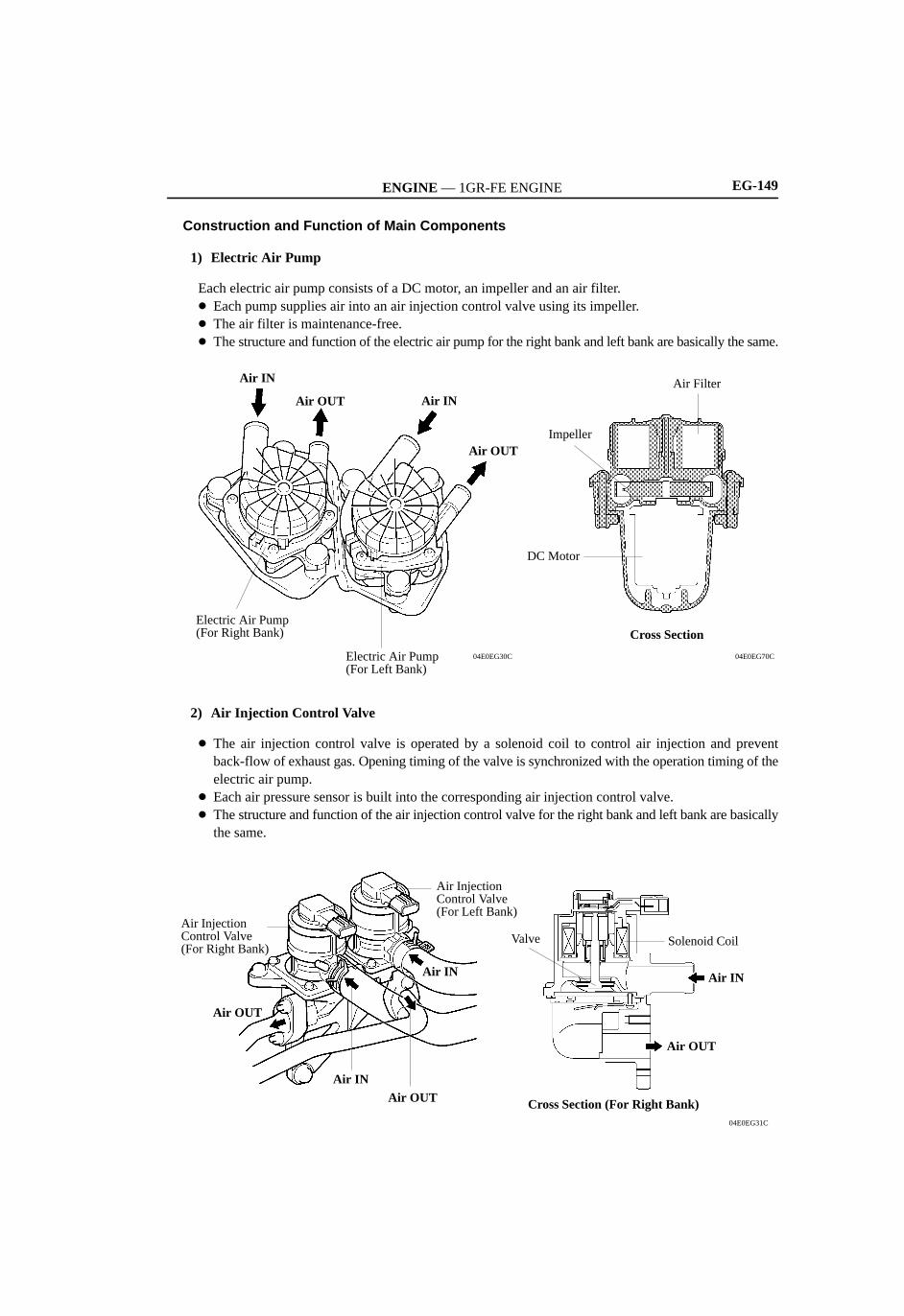
ENGINE — 1GR-FE ENGINE EG-149
Construction and Function of Main Components
1) Electric Air Pump
Each electric air pump consists of a DC motor, an impeller and an air filter. Each pump supplies air into an air injection control valve using its impeller. The air filter is maintenance-free. The structure and function of the electric air pump for the right bank and left bank are basically the same.
04E0EG70C
Cross Section
Air Filter
Impeller
DC Motor
Electric Air Pump(For Right Bank)
Electric Air Pump(For Left Bank)
Air OUT
Air INAir OUT
Air IN
04E0EG30C
2) Air Injection Control Valve
The air injection control valve is operated by a solenoid coil to control air injection and preventback-flow of exhaust gas. Opening timing of the valve is synchronized with the operation timing of theelectric air pump.
Each air pressure sensor is built into the corresponding air injection control valve. The structure and function of the air injection control valve for the right bank and left bank are basically
the same.
04E0EG31C
Cross Section (For Right Bank)
Air OUT
Air IN
Solenoid CoilValve
Air Injection Control Valve (For Left Bank)
Air IN
Air OUTAir IN
Air OUT
Air Injection Control Valve (For Right Bank)

ENGINE — 1GR-FE ENGINEEG-150
3) Air Pressure Sensor
The air pressure sensor consists of a semiconductor, which has a silicon chip that changes its electricalresistance when pressure is applied to it. The sensor converts the pressure into an electrical signal, andsends it to the ECM in an amplified form.
The structure and function of the air pressure sensor for the right bank and left bank are basically thesame.
257MA22
(kPa)150Air Pressure45
0.5
OutputVoltage
4.5
(V)
Air Pressure ofElectric Air Pump
Sensor Unit
04E0EG32C
The ECM detects operation of the air injection system based on signals from the air pressure sensor asfollows:1) When the electric air pump is ON and the air injection control valve is closed, the pressure is stable.2) When the electric air pump is ON and the air injection control valve is open, the pressure drops slightly
and becomes unstable because of exhaust pulses.3) When the electric air pump is OFF and the air injection control valve is closed, the pressure remains
at zero.4) When the electric air pump is OFF and air injection control valve is open, the pressure drops below zero
and becomes unstable because of exhaust pulses.
273GX81
Electric Air Pump: ONAir Injection Control Valve: Closed
Time0
Pressure
Example: 1
Electric Air Pump: OFFAir Injection Control Valve: Closed
Time0
Pressure
Example: 3
Electric Air Pump: ONAir Injection Control Valve: Open
Time0
Pressure
Example: 2
Electric Air Pump: OFFAir Injection Control Valve: Open
Time0
Pressure
Example: 4
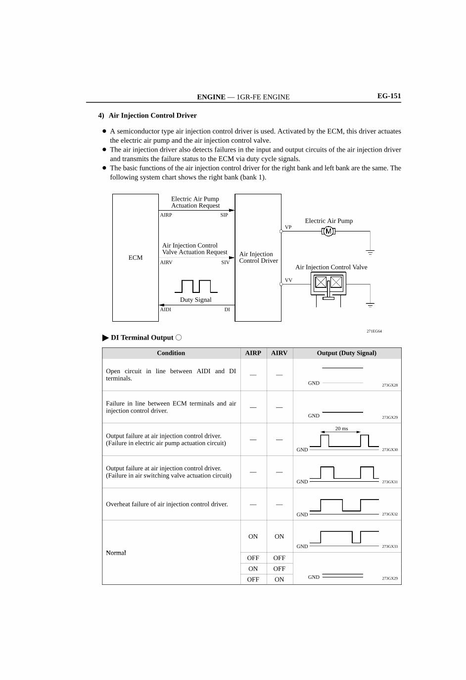
ENGINE — 1GR-FE ENGINE
273GX28
273GX29
273GX33
273GX32
273GX31
273GX30
273GX29
GND
20 ms
GND
GND
GND
GND
GND
GND
EG-151
4) Air Injection Control Driver
A semiconductor type air injection control driver is used. Activated by the ECM, this driver actuatesthe electric air pump and the air injection control valve.
The air injection driver also detects failures in the input and output circuits of the air injection driverand transmits the failure status to the ECM via duty cycle signals.
The basic functions of the air injection control driver for the right bank and left bank are the same. Thefollowing system chart shows the right bank (bank 1).
271EG64
Air Injection Control Valve
Electric Air Pump
Air InjectionControl Driver
Duty Signal
Air Injection ControlValve Actuation Request
Electric Air PumpActuation Request
ECM
VP
AIRP SIP
AIDI DI
AIRV SIV
VV
DI Terminal Output
Condition AIRP AIRV Output (Duty Signal)
Open circuit in line between AIDI and DIterminals.
— —
Failure in line between ECM terminals and airinjection control driver.
— —
Output failure at air injection control driver.(Failure in electric air pump actuation circuit)
— —
Output failure at air injection control driver.(Failure in air switching valve actuation circuit)
— —
Overheat failure of air injection control driver. — —
Normal
ON ON
NormalOFF OFF
ON OFF
OFF ON