copy - nasa
TRANSCRIPT

NASA CONTRACTOR
REPORT
o
!
z
NASA CR-2026
COPY
A COMPUTER PROGRAM
FOR THE CALCULATION
OF THERMAL STRATIFICATION
AND SELF-PRESSURIZATION IN
A LIQUID HYDROGEN TANK
by R. IV. Arnett and R. O. Voth
Prepared by
NATIONAL BUREAU OF STANDARDS
Boulder, Colo.
/or Lewis Research Center
NATIONAL AERONAUTICS AND SPACE ADMINISTRATION • WASHINGTON, D. C. • MAY 1972

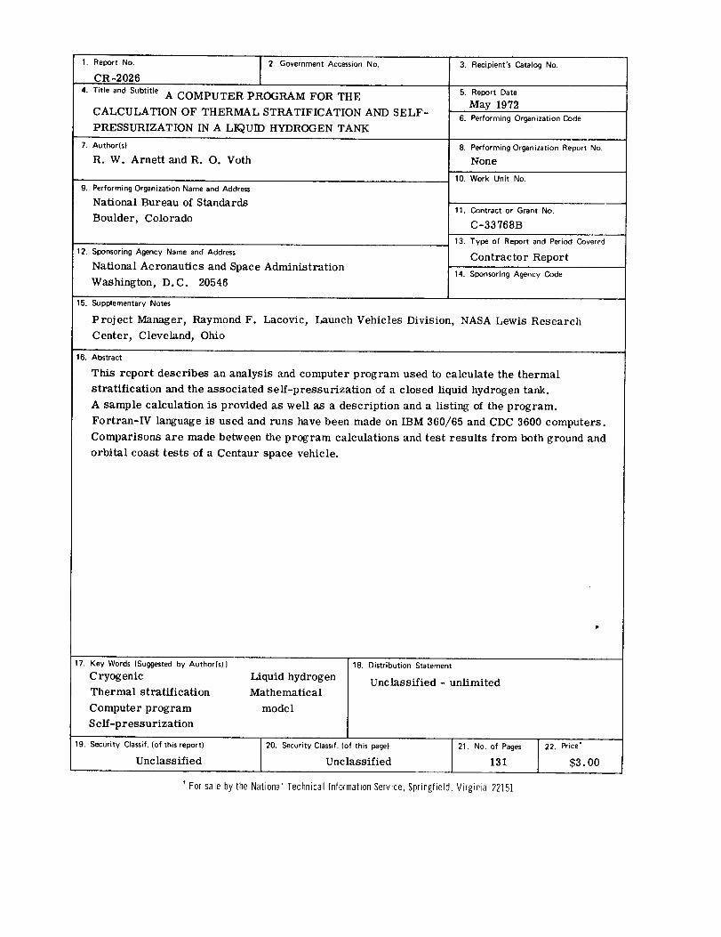
1. Report No. i 2. Government Accession No.
ICR-2026
4. Title and Subtitle A COMPUTER PROGRAM FOR THE
CALCULATION OF THERMAL STRATIFICATION AND SELF-
PRESSURIZATION IN A LIQU]I) HYDROGEN TANK
7. Author(s)
R. W. Arnett and R. O. Voth
9. Performing Organization Name and Address
National Bureau of Standards
Boulder, Colorado
12. Sponsoring Agency Name and Address
National Aeronautics and Space Administration
Washington, D.C. 20546
3. Recipient's Catalog No.
5. Report Date
May 1972
6. Performing Organization Code
8. Performing Organization Report No.
None
10. Work Unit No.
11. Contract or Grant No.
C-33768B
13. Type of Report and Period Covered
Contractor Report
14. Sponsoring Agency Code
15. Supplementary Notes
Project Manager, Raymond F.
Center, Cleveland, Ohio
Lacovic, Launch Vehicles Division, NASA Lewis Research
16. Abstract
This report describes an analysis and computer program used to calculate the thermal
stratification and the associated seE-pressurization of a closed liquid hydrogen tank.
A sample calculation is provided as well as a description and a listing of the program.
Fortran-IV language is used and runs have been made on IBM 360/65 and CDC 3600 computers.
Comparisons are made between the program calculations and test results from both ground and
orbital coast tests of a Centaur space vehicle.
17. Key Words (Suggested by Author(s)}
Cryogenic
Thermal stratification
Computer program
Self-pressurization
19. Security Classif. (of this report)
Unclassified
Liquid hydrogen
Mathematical
model
18. Distribution Statement
Unclassified - unlimited
20. Security Classif. (of this page}
Unclassified
21. No, of Pages
131
' For sale by the National Technical Information Service, Springfield, Virginia 22151
22. Price*
$3. oo


TABLE OF CONTENTS
Section
1.0
2.0
3.0
4.0
5.0
6.0
7.0
8.0
SUMMARY
INTRODUC TION
PREVIOUS STUDIES
ANAL YSIS
4.3
Boundary Layer Equations
Growth and Temperature of the Stratified
L aye r
Ullage Pressure Calculation
RESULTS
SAMPLE CALCULATION
SYMBOLS
REFERENCES
APPENDICES
Ao Mathematic al Development
A. 1 Momentum-Force Balance Equations
A. 2 Energy Balance Equation
A. 3 Gross Energy Balance Equation
A. 4 Solution of Equations
A. 5 Growth of Stratified Layer
A. 6 Temperature Distribution
A. 7 Ullage Mass Determination
So Computer Program
B. 1 Program DescriptionB. 2 Program Nomenclature
B. 3 Program Listing
Page
1
Z
3
6
7
13
15
18
27
41
44
47
47
47
51
53
53
54
55
58
6Z
62
68
72
iii

Figure
1
2
3
4
5
6
7
8
9
10
11
LIST OF ILLUSTRATIONS
Assumed velocity and temperature variation
across the boundary layer
As sumed geometry
Boundary layer nomenclature
Temperature gradients at the liquid surface
Self pressure rise comparison for Plum Brook
B-2 test
Ullage temperature comparison for Plum Brook
B-2 test
Self pressure rise comparison for Centaur
AC-8 flight
Ullage temperature comparison for Centaur
AC -8 flight
Effect of heat input location, small ullage volume
Effect of heat input location, large ullage volume
Tank configuration, actual and assumed, for
Plum Brook B-2 test comparison
Page
9
i0
Ii
16
19
20
2Z
Z3
25
Z6
28
iv

Number
1
Z
3
4
LIST OF TABLES
Parahydrogen thermodynamic property data
Input data for the Plum Brook B-2 test comparison
Parahydrogen kinematic viscosity data
Heat flux input data for the Plum Brook B-2
test comparison
Printout for the Plum Brook B-2 test program
Adjusted pressure rise values
Page
31
3Z
33
33
35
39
V


A COMPUTER PROGRAM FOR THE CALCULATION
OF THERMAL STRATIFICATION AND SELF-PRESSURIZATION
IN A LIQUID HYDROGEN TANK
R. W. Arnett and R. O. Voth
i. 0 Summary
This report presents a computer program developed for calcu-
lating thermal stratification and the associated self-pressurization of
a closed liquid hydrogen tank. The computer program is written in
Fortran IV language and has been run on both a Control Data Corpora-
tion 3600 computer and an International Business Machines 360/65
computer.
This report also presents the mathematical development of the
computer program. The boundary layer equations required for the
mathematical development used the classical approach for solution of
the turbulent boundary layer equations, except that no assumptions were
made as to the form of the thickness and velocity parameter solutions.
The resulting mathematical expressions require symmetry about the
vertical axis but permit axial variations of geometry and heat flux.
Comparison of the pressure rise data from both a ground test
and orbital coast data is provided with the tank pressure calculation
and test data agreeing within 4% or better.
Parametric data for a ground test conducted by the NASA-Lewis
Research Center are used for a sample calculation with the input format
and a typical program printout used to illustrate the use of the program.
The program incorporates subprograms containing thermodynamic and
physical properties of parahydrogen. These subprograms can be re-
placed by subprograms incorporating the properties of other fluids as
desired. A complete listing of the computer program is included as
an appendix to the report.
Z. 0 Introduction
During the launch sequence or space coast of a chemical or
nuclear rocket using liquid hydrogen as a propellant, it becomes
necessary, at some time prior to engine ignition, to suspend venting
of the hydrogen tank. This cessation of venting may be required as a
safety measure and may also be necessary from an operational stand-
point. Duration of this 'locked up' condition may persist for several
minutes.
During the time interval that the tank is 'locked up' heat trans-
fer through the tank walls results in energy increase in both the liquid
and the ullage space vapor. Experience has shown that this energy in-
crease is not uniformly distributed in either the liquid or vapor, but
rather that higher temperatures occur in the topmost layers of both
the liquid and vapor regions. This phenomenon is described as thermal[I, Z, 3,4]
stratification and has been reported by numerous observers
Associated with this temperature stratification is a rise in tank
pressure due to a combination of heat transferred to the ullage vapor
plus possible vaporization of a portion of the liquid. A means for pre-
dicting the amount of pressure rise as it varies with time and tank wall
heat flux is needed in order to properly plan for propellant management,
to determine tank structural stresses, to determine tank venting re-
quirements and possibly to foresee the need for additional pressurant
gas. The extent of liquid temperature rise, separate from its effect
on the tank pressure, is also needed in order to determine the effect
on pump performance. Excessive temperatures can result in cavita-
tion due to reduction in NPSH, thus either damaging the pump or ad-
versely affecting the pump performance.

The purpose of this report is to present an analysis and a com-
puter program that can be used to calculate the thermal stratification
and self pressurization in a liquid hydrogen tank. The program results
compare well with certain space vehicle liquid hydrogen tank self pres-
surization data obtained from both a space coast and a ground test.
The ground test is used here as a sample problem to aid the user in
employing the program. The program was written using liquid hydrogen
properties but the basic program should also be applicable for other
fluids.
The program is written in Fortran IV for an IBM 360/65 series
computer. A program listing and a description for each of the program
subroutines is provided in this report.
3.0 Previous Studies
Since the early work of Huntley [1], numerous papers (see
additional references) relating to stratification phenomena have
appeared. Many of these papers were directed at the thermal strati-
fication but did not consider the self-pressurization aspect. Of the
reported work, that of the group at Lockheed (LMSC) was the most
concerned with pressure rise in addition to the thermal aspectsLS,_7,_9].r_
Schmidt, et al[I0]. utilized external pressurization in a vessel
with negligible sidewall heat leak to measure the liquid thermal gradient
due to heat transfer at the liquid surface. This test arrangement re-
sulted in a condensing type of heat and mass transfer at the liquid
vapor interface. Good correlation of the resulting temperature dis-
tribution throughout the liquid with the error function solution for a
semi-infinite solid was established.
Clark [1 1]reviewed the status of the generalized pressurization
and stratification problem. In this review, it was pointed out that
numerous assumptions are necessary in order to solve the mathematical
expressions involved. The validities of some of the assumptions which
are commonly made require evaluation by careful experimentation,
as Clark indicated. In addition, he pointed out that the interracial
phenomena associated with mass and energy transfer, while quite
complex, can probably be taken to be in thermodynamic equilibrium
with little error.
Subsequent to the review of Clark [11], no comprehensive
review of the situation has been published. Urquhart [1Z] made a
survey but did not publish a comprehensive review. He concluded
that the finite difference approach of Clark and Barakat[ lr 3] was
thermodynamically excellent but contained restrictive assumptions,
treated the laminar case only, and required excessive amounts of
computer time. Urquhart further concluded that the work of the LMSCIs, 6, 8]
group was representative of the boundary layer approach to
stratification. He further suggested certain improvements which he
felt would be beneficial.
Urquhart suggested the following improvements to the LMSC
solution.
1. Utilization of both laminar and turbulent solutions to the
boundary layer flow, splicing these together where the laminar
to turbulent transition occurs.
Present Authors Note: It may be pointed out that for liquid
hydrogen (LHz) iu a normal earth gravity field with a relatively
low heat flux of 10 mW/cm 2, a turbulent boundary layer regime
is attained within Z to 6 cm from the initiation point of boundary
layer growth. Thus, this suggested addition would seem to have
marginal benefit.
4
Z. Incorporate transient effects of the establishment of the
boundary layer.
Present Authors Note: It appears that, in the majority of cases,
the vessel has been exposed to a constant heat flux for some time
and the liquid is saturated at its ambient pressure. Stratifica-
tion then begins at the time the vessel vent is closed; since
steady state conditions already exist in the boundary Layer,no
significant transient effects occur.
3. Consider the possibility of nucleate boiling in the boundary
1 aye r.
Present Authors Note: This would seem to be a reasonable
suggestion since the temperature rise in the boundary layer
is likely to approach or exceed the local saturation tempera-
ture, particularly in the upper portion of the vessel. However,
such boiling will likely occur only in the upper regions of the
tank, thus affecting only a small portion of the boundary layer.
Furthermore, since some vaporization is likely to occur any-
way, the exact location of such vaporization is probably not
of major importance.
4. Use variable fluid properties as the calculations proceed
in real time.
Present Authors Note: This seems to have merit and could be
considered, although the increased complexity does not seem
to be justified at the present time in view of uncertainties in
other areas.

In summary, it seems that the work of the LMSC group is
representative of the most practical approach to the stratification and
pressurization phenomena. The approach described in this report
also utilizes the basics of the turbulent boundary layer approximate
approach. However, it does not assume the vertical flat plate boundary
layer, nor does it assume either a "mixed ullage" or a "saturated
vapor" temperature for the ullage space.
The work reported here is an extension and refinement of ar 1
paper presented by Arnett and Millhiser in 1965 [14]. Important changes
from this previous development include the solution for the boundary
layer thickness and the velocity parameter without assuming a parti-
cular mathematical form; the removal of modifying factors which
formerly were used to force continuity of the boundary layer flow;
and departure from the previously used method for forcing decay of
the boundary layer in the thermally stratified layer.
4.0 Analysis
The development of the equations here will be in functional
notation, except for simple relationships. More complete equations
are presented in the Appendices.r 1
Eckert and Jackson t15] developed expressions for free con-
vection turbulent boundary layer flow on a heated vertical flat plate in
a semi-infinite medium. The method of attack parallels that used by
Von KarmanL16,r 17] for a laminar boundary layer. This same approach
is used here, with modifications to adapt it to an inclined wall of finite
radius, i.e., a conical shape.

4. 1 Boundary Layer Equations
Prediction of thermal stratification and the associated pressure
rise is based upon the assumption that heat transferred through the
vessel walls is carried toward the upper portions of the vessel via
a free convection boundary layer. Heat entering the boundary layer
through the liquid wetted portion of the tank thus tends to accumulate
in a layer adjoining the liquid surface and is manifested by a rise in
temperature of this layer. Evaporation at the liquid-vapor interface
usually occurs, depending on the pressure in the ullage space, this
being determined in turn by the initial ullage space conditions and the
amount of heat subsequently transferred to the ullage. The temperature
at the liquid surface determines the tank ullage pressure; if vaporiza-
tion occurs the liquid surface will be cooled due to the vaporization
while if condensation occurs the temperature, and therefore the pressure,
will tend to rise.
Three parameters serve to describe the boundary layer flow:
(1) The temperature variation across the boundary layer, (Z) thickness
of the layer, and (3) the velocity distribution across the layer. For
this development, assumptions of the form for the dimensionless tem-
perature and velocity variations are the same as those used by Eckert[15]
and Jackson . These are
6)/6) = 1 - (y16) 1/7 , (1)w
an d,
u/U = (y/6) 1/7 (1 - y/8) 4. (2)

The three parameters required then are 8w, 6, and U. These are
interdependent and are functions of vertical location in the tank, acce-
leration field, the wall heat flux, and the fluid properties. The manner
in which 8/8 and u/U vary across the boundary layer, as described byw
(1) and (2),is shown in figure 1. Figure 2 displays the tank configura-
tion assumed for the mathematical model.
A fluid element of thickness, dx, bounded by two planes normal
to the vessel axis and a distance x from the bottom of the tank, is
analyzed in order to formulate a set of equations. A section of this
annular boundary layer is shown in figure 3.
The change in momentum flow, parallel to the wall, in crossing
the element dx is equated to the forces acting, also parallel to the
wall, on the element, i.e.,
x+dx
d Z_x (rAu) dx = F = F B + F S.x
Momentum flow crossing plane "a" is expressed as
5
_ rhu = f (u, y, R, p, ¥, x),U
y=o
and the change in r_u in the dixtance dx is given by
5
y=o
The buoyant force in the direction of flow is represented by
(s)
(4)
(4a)
FB = fB (Y' R, x, 0, 7 ),
while a shear force along the direction of flow is described as
FS = fs ( *w' R, y, x).
(5)
(6)

10 I l l l i l i l l
m
08 m
06--
u/U -
f , , 'tO0 0.2 0.4 0.6 0.8 I_0
y/8
Figure 1 Assumed velocity and temperature variation across
the boundary layer.

L
Lc
X
f
R C
h
I StratifiedLayer
Z
Figure 2 Assumed geometry
10

ACCELERATION
\q
_"- Tank Woll
X
Figure 3 Boundary layer nomenclature
Ii

A wall shear stress correlation by Blasius [18' page 143] .IS
used to substitute for T in equation (6). By combining the Reynolds
analogy[18, page 203] w,relating viscous shear stress to conductive heat
transfer, with the Blasius correlation and a Prandtl number correctionF I
due to Colburn [19' page 5ZI; 18, page 324],a suitable substitution can
also be made for @ . The basic momentum equation is formed byW
equating equation 4a to the algebraic sum of equations (5) and (6).
the indicated integrations and differentiations are performed,
When
of the form
an equation
dU d6
- A (5 U) + B (5 U)-_-x (7)dx ' '
is obtained.
A second equation can be developed by analyzing the heat transfer
balance on the element under consideration. For the purpose of this
analysis, the fluid in the core is considered to be at the datum condi-
tion. Since fluid entering or leaving the boundary layer at y = 6 is
at the datum condition, there is no heat transferred across this boundary.
Thus, the only additional heat entering is that transferred through the
wall at y = o. Equating the heat flux through the wall to the change in
heat flow across the element, and performing the mathematical manipu-
lations, results in an equation of the form
dUd6dx - C (5,U) + D(5, U)-_--x (8)
A third equation can be derived by equating the rate of heat
transported across a horizontal plane located at x, to the rate of heat
entering the fluid through the tank wall below this plane. Solving the
resulting equation and rearranging yields an equation of the form,
u = E (6, x). (9)
12

Allowance for varying heat flux over the tank height is accomplished
by defining a term, qm' such that
X X
qlTl _0 dA--_o qw d A- (lO)
Thus, if qw varies axially along the tank (circumferential uniformity
is assumed), qm will reflect the total heat flux pattern below the plane
at x. The local heat flux, qw' is assumed constant with time due to
tank insuIation, qm is used wherever substitution for 8 is required.W
Simultaneous solution of equations (7), (8), and (9) is achieved by an
iteration using Newton's method.
4.2 Growth and Temperature of the Stratified Layer
An arbitrary stratified layer thickness is selected and the time
for the boundary layer flow to occupy the stratified layer volume is
determined. The volume flow rate parallel to the wall in the boundary
layer at any horizontal plane can be determined by integration across
the boundary layer. An incremental time sufficient for a boundary
layer volume flow to occupy an arbitrarily small volume immediately
above the horizontal pIane can then be determined,
_V,At" _
5
( J_o udA)x
A summation of these time increments for all volume increments
above an arbitrary plane will supply the time required, t --_ At, for
the stratified layer to occupy the volume above that plane.
The problem remains as to how much energy is contained in
the stratified layer, and how that energy is distributed within the layer
as reflected by the temperature distribution.
13

Since we are considering a steady state boundary layer, i.e.,
the energy content of the boundary layer itself does not change with
time, all of the energy entering the tank sidewall during the stratified
layer growth time must be contained within the stratified layer.
L
Q : tqm j dA.o
Based upon inspection of various experimental stratified layer
temperature gradients,
form is assumed:
a vertical energy distribution of exponential
Thus,
(il)
E(Z) : m Z n (IZ)
We write
dQ = E(Z) dV, (13)
and
o : i E(Z) dV. (13a)O
Utilizing equations (ii), (iZ), and (13) together with the tank geometry,
the value of m in the energy equation can be determined and the tem-
perature calculated from the energy and mass content of any incremental
volume. The above procedure thus enables establishment of the energy
distribution and the corresponding temperature gradient through the
stratified layer.
In the ullage space, an iteration method is used to determine
the thickness of the ullage stratified layer corresponding to the time
ele_nent previously determined for the assumed thickness of the liquid
stratified layer. Existence of a free convection boundary layer in the
ullage space, prior to the closing of the vent, is assumed although it is
14

recognized that a gradual change in the defining parameters of the
boundary layer occurs as the pressure and temperature of the ullage
vapor changes. This change is automatically included since ullage
space boundary layer calculations are redone for each step change in
the liquid stratified layer, with changes in the temperature, pressure,
and vapor properties incorporated in the new calculations.
4.3 Ullage Pressure Calculation
A determination of the pressure existing in the ullage space is
made following each calculated time increment.
Initially, the mass of gas present in the ullage space is computed,
based upon a uniform temperature (assumed saturated at the initial
pressure), pressure, and ullage volume. Using an iteration procedure,
the amount of liquid vaporized due to the heat flux through the wails is
balanced against the pressure rise due to the temperature increase in
the ullage space and the increased mass due to vaporization. Vapori-
zation is allowed in a surface layer of thickness Z1, as illustrated in
figure 4a, with the liquid in this layer being cooled to a uniform temper-
ature of T by extraction of the latent heat required by the mass vapor-s
ized. Using the temperature distribution for the ullage space together
with an assumed pressure, a mass for the ullage space is determined;
this is then compared with the initial mass, adjusted for the amount of
liquid vaporized. Successive iteration steps will result in bracketing
the value for the liquid mass evaporated (or condensed) and the change
in ullage mass required for equilibrium. A linear interpolation is
then used to establish a final value for the mass evaporated and the
corresponding ullage pressure.
When conditions are such that the calculated ullage pressure is
greater than the surface liquid saturation pressure when no mass is
evaporated, then condensation of some ullage vapor is required. Under
15

Interface
8s
-" 8_mox
( O ) Vaporization
Ga.__ss .Tj_ ,Ts
Interface __/j
Liguid/_'_
TB-...._
-" 8s r
(b) Condensation
Figure 4 Temperature gradients at the liquid surface.
16

this condition, i.e.,when the 8asuration temperature corresponding to
the ullage pressure is greater than the liquid surface temperature
determined during the stratified layer calculations, then an incremental
ullage mass is condensed, with the temperature increase of the liquid
layer being described by an error function as reported by Schmidt,[10]
et al. , figure 4b. Again successive iterations result in a pressure
being established such that the ullage space pressure is in equilibrium
with the liquid surface temperature.
When the saturation temperature corresponding to the ullage
pressure matches the liquid surface temperature, then that pressure
is recorded as the ullage pressure corresponding to the time and a
new liquid stratification depth is selected to initiate a new series of
calc ulations.
Heat transferred through the bottom of the tank is treated separ-
ately from the computer program. Application of this program has been
limited to heat flux patterns where the bottom heat flux is relatively
small and its affect has been treated by assuming that the thermal
energy entering is uniformly distributed in the liquid. This results
in a uniform increase in T B. It is found that the increase in T B is
very small and has a negligible affect on the liquid properties. As a
result, this increase in T B can be added to the surface temperature of
the liquid and the corresponding saturation pressure used as the tank
pressure. In all cases encountered, this correction has amounted to
only a small increase in the ullage pressure.
Complete development of the equations and a description of the
computer program used to solve the equations and calculate the various
outputs are included as appendices.
17
5. 0 Results
Several calculations of pressure variation with time, using a
range of parameters which were selected to bracket the probable
actual parameters, have been made; in addition, various calculations
were made using the best estimates of input parameters matching
various actual tank pressure rise data. One of these reflects input
values for an unpublished experimental pressure rise test in the
Plum Brook B-Z space simulation facility, while another calculation uses
input parameters telemetered to ground stations during the coast phase
of the Centaur AC-8 flight [Z0].
The set of experimental data obtained during the Plum Brook
B-Z tests represents results of the most accurately instrumented and
most closely controlled experimental work so far performed on the
Centaur vehicle pressure rise phenomenon.
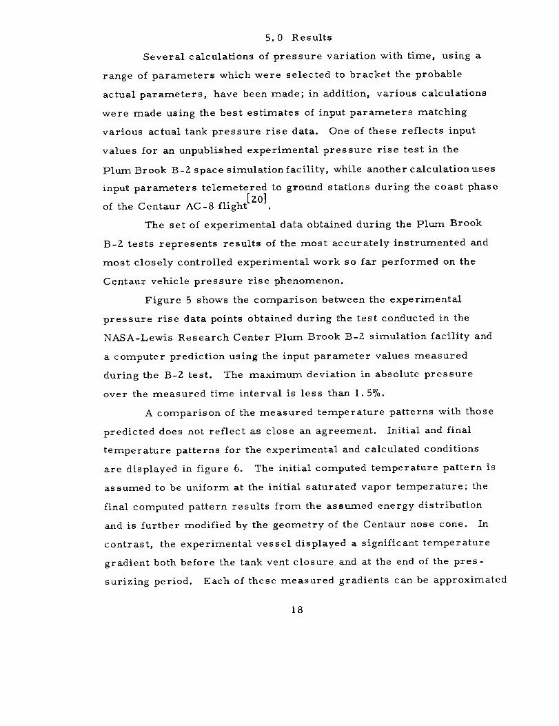
Figure 5 shows the comparison between the experimental
pressure rise data points obtained during the test conducted in the
NASA-Lewis Research Center Plum Brook B-Z simulation facility and
a computer prediction using the input parameter values measured
during the B-Z test. The maximum deviation in absolute pressure
over the measured time interval is less than I. 5%.
A comparison of the measured temperature patterns with those
predicted does not reflect as close an agreement. Initial and final
temperature patterns for the experimental and calculated conditions
are displayed in figure 6. The initial computed temperature pattern is
assumed to be uniform at the initial saturated vapor temperature; the
final computed pattern results from the assumed energy distribution
and is further modified by the geometry of the Centaur nose cone. In
contrast, the experimental vessel displayed a significant temperature
gradient both before the tank vent closure and at the end of the pres-
surizing period. Each of these measured gradients can be approximated
18
E
Z
n,-
or}or)I.dn,"13_
_,,Z
I--
ZI.lJ
0n,-
-1-
iciI
0i
.J
14
13-
12-
0
- O@
-oeI
_--0
II i0
Figure 5
I ' I ' I
O--LeRC Experimental
• - Computer Results
0
0
(I
0
0
0
0
0
0
0
0
O•
0
i
I
I
I
m
i0
0
I I I , I , I I40 80 120 160 200
TIME FROM LOCKUP,s
Self pressure rise comparison for Plum Brook B-2 test.
]9
I I I I
\
\\\\\
I T i0 0 0 0 00 0 0 0 0uO '_" _r) OU --
WO ' 3DV_-I_IAS (]In017 3AOSV :IONVISi(]
O
0Go
0I,.-
8
0
0
0
OO04
4_
P'3
!
OO
,,,-,,-I
13.,
o
W o
n," oIll13,.
I-- ®
4,_
,'-'-,I
,,,D
I:10°_,_
Z0

with a linear temperature pattern although a second or third degree
function would achieve a somewhat better fit.
For the purpose of determining the ullage pressure, a precise
knowledge of the temperature distribution in the ullage is not required;
rather, the value of the change in internal energy is of prime import-
ance -- regardless of the distribution of that energy. For a perfect
gas the chan_e in pressure of a constant volume system is determined
by the ' ange in internal energy. Thus the nearly perfect gas be-
havior of hydrogen at the pressures encountered with liquid hydrogen
rocket tanks results in the pressure being determined by the internal
energy w and affected only slightly by the temperature distribution.
A close examination of figure 6 reveals that the final calculated tem-
perature pattern appears to have a mean value well below the final
experimental temperature. This is understandable when one realizes
that the assumption of saturated vapor for the initial condition results
in more ullage mass than is actually the case; thus the addition of the
required internal energy will result in a lower final temperature as the
plot shows. However the determining factor in the pressure rise is
the change in internal energy as discussed above.
Comparisons of calculated pressure rise and temperature
patterns with data telemetered from the Centaur AC-8 vehicle during
a low-g coast phase [2"0] are seen in figures 7 and 8 respectively. The
calculated pressure rise is seen to be slightly lower than the telemetered
data; the computed pressure is within 4% of the absolute pressure
measured throughout the interval, while the pressure difference is a
maximum of 15% lower than the measured pressure difference. Ullage
temperature pattern comparisons again are not as well matched. The
initial uniform saturated vapor temperature assumed for the calcula-
tions is seen to be a poor approximation to the actual temperature
Z1

uO
m
_')
Q
CO m.
' E(_ o
0 •
_uJoIN
I I I
%
'3_nss3_d
Mm
MNVI N390EIOAH (]InO17
00
00
00
g
00
0-- 0
0-- 0
00
O0
!
v o
0 __J _
0 o(..)
.T-I
W u
ZZ

\\\
\\\
0 (.9
d_J
\
\
00
I I , I I0 0 0 00 0 0 0_- rO oJ --
w0 ' 30V_1_117$ 0117017 3AOSV 30NV±SICI
O
O
O
O
J
°_
O0
I
L_
U
O
ILl o
n_ oW
_ s2
O0
23

pattern. The final calculated temperature distribution has a shape
similar to that of the telemetered data but increases more rapidly in
the upper parts of the tank. As mentioned previously the temperature
distribution in the ullage space does not appear to be of great import-
ance -- of more significance are the mass and total energy content
and volume of the ullage vapor. A comparison of the energy content
by calculation with that represented by telemetered data shows more
energy is stored as sensible heat in the liquid for the actual case than
is predicted from the theoretical calculations.
The influence of the location of heat input to a Centaur LH 2
tank is shown in figures 9 and 10. Figures 9 and 10 use normalized
coordinates in order to compare results more easily. The normalized
= is the maximum pressurepressure is defined as PN P/Pc' where Pc
attained for the uniform heat flux case; likewise a normalized time is
used, t N = t/t c, where t c is the time to attain the maximum pressure
for the uniform heat flux case. Cases 1, Z, and 3 shown in figure 9
are for a small (8°7o) ullage space and have the same total heat input
to the tank for each case. A uniform heat flux was used in Case 1,
a wetted wall heat flux 10 times as great as the ullage wall heat flux
for Case Z, and an ullage wall heat flux 10 times as great as the wetted
wall heat flux for Case 3. Note that increasing the heat input to the
ullage space increases the rate of pressure rise while increasing the
heat into the liquid decreases the pressure rise rate, the total heat
input being the same in each case. Figure 10 shows a similar result
for the situation of a large (65%) ullage volume -- Case 4 being uniform
heat flux, Case 5 high liquid heat flux, and Case 6 high ullage heat flux,
again with the same total heat flux in all three cases. The trend of
pressure rise due to location of maximum heat flux is seen to be the
same for both the small and the large ullage cases.
Z4

I i r ' I i r _ I
ILl
x Z)x _ J-, _ 0
.._ x >
0
o ._ "_
/ m
\//\
x/\
i I L I I Io,I 0 co (,o-- -- 0 0
F
o
OJ >
-- Q;"L0
0 LIJ--" _ E
m
I--_ F
I:_ oILl
--(_. N u0 -- 0
-
0- Z
o
_ oo d
c_
_q
o',
c_
3S1_1 3WASS':IWd O":IZIqVIAINON
Z5

_D
04 o
3SIEI 3EInSS=IEIcl CI=IZI7'_/_tgON
Z6
6.0 Sample Calculation
A sample calculation, using the input parameters from the
Plum Brook B-Z test, is presented here. Pertinent parameters from
the Plum Brook B-Z test are as follows:
Liquid (hydrogen) level at station 333.3.
Normal earth gravitational field.
Initial tank pressure, 11.41 N/cm Z (16.55 psia).
Final tank pressure, 13.79 N/cm Z (Z0 psia).
Time, lockup to final pressure, 199 s.
Heat flux:
Intermediate bulkhead (bottom of tank) 440 W {1500 Btu/h).
Wetted sidewall 5568 W (19000 Btu/h).
Ullage sidewall 1495 W (5100 Btu/h}.
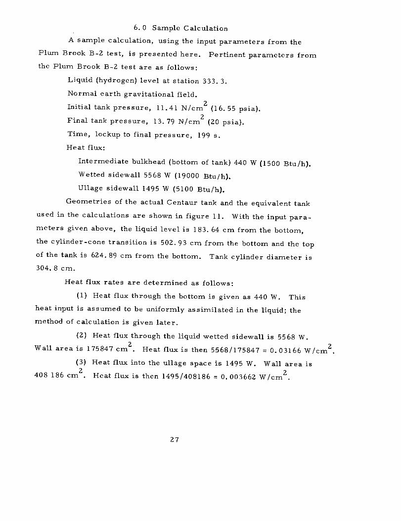
Geometries of the actual Centaur tank and the equivalent tank
used in the calculations are shown in figure 11. With the input para-
meters given above, the liquid level is 183.64 cm from the bottom,
the cylinder-cone transition is 50Z. 93 cm from the bottom and the top
of the tank is 624.89 cm from the bottom. Tank cylinder diameter is
304.8 cm.
Heat flux rates are determined as follows:
(1) Heat flux through the bottom is given as 440 W. This
heat input is assumed to be uniformly assimilated in the liquid; the
method of calculation is given later.
(Z) Heat flux through the liquid wetted sidewall is 5568 W.
2 W/cm 2Wall area is 175847 cm . Heat flux is then 5568/175847 = 0.03166
(3) Heat flux into the ullage space is 1495 W. Wall area is
Z W/cm Z.408 186 cm . Heat flux is then 14951408186 = 0.00366Z
Z7

162.04Sta //_-_-_\ 624.89cm
Tank Equivalent ,'N
//- Tank "%-502.93(T.P.) 219-
0°_
0
O3
333.3 --
D = 304.8 cm =
LIQUID SURFACE
405.6-- --0
Figure tl
0
oE0
4--
_.)0t-O
¢0
183.64
Tank configuration, actual and assumed, for Plum Brook B-Z
test comparison,
28

An initial pressure of 11.41 N/cm _ is equivalent to i. 1262 atm,
the value used as the input for l°S. A limiting pressure of i. 40 atm,
slightly in excess of the ]3-2 test final pressure of 13.79 N/cm 2, is
used for PL.
A summary of the input used for the computer program is as
follow s:
Gamma = 45.0 deg (nose cone half angle).
Acceleration field,"G" =980.67 cm/s 2
LC =502.93 cm
L = 183.64 cm
H = 624.89-L = 441.25 cm
IZC =152.4 cm
PS = I. 1262 atm
loL =1.40 atm
Heat flux, given at distance X from the bottom of tank is:
qw
0 0.03166 W/cm 2 .
183.64 cm 0.03166 W/cm _ .
184.0 cm 0.003662 W/cm 2.
502.93 cm 0. 003662 W/cm _.
624. 89 cm 0. 003662 W/cm 2.
Note that a value for the heat flux must be given at the liquid level
and at the cylinder cone transition as well as at the bottom and top of
the tank. Different heat flux values may be given at any other location
in addition to these.
In addition to the above inputs based upon the physical condition,
additional required inputs are chosen as follows:
Z9
Liquid depth increment, DL, assigned value of 5.0 cm.
Number of increments used in stratified layer, ZINC = 50.0.
POWER = Z.0, exponent used to describe energy distribution in
the stratified layer; must be non negative.
TAMB = 300.0 K.
The data cards, located at the end of the program deck, are
made up of four sets. The first set, Table I, is composed of 40 cards,
in pairs, containing thermophysical properties for parahydrogen in
the following order and within the punch card columns indicated:3
pressure, arm (I-8); liquid specific volume, cm /g-mol (9-16);
3
liquid (_P/_P)T' cm .atm/g-mol (17-Z4); liquid (_P/_T)p, atm/K (Z5-3Z);3
vapor specific volume, cm3/g-mol (33-40); vapor (_P/_P)T' cm .atm/
g-mol (41-48); vapor (_P/_T)p, atm/K (49-56); liquid entropy, J/g-mol-
K (57-64); vapor entropy, J/g_mol-K (65-7Z); saturation temperature,
K (73-80); next card, vapor specific heat, J/g-mol. K (1-8); liquid
specific heat, J/g-mot.1< (17-Z4).
These property data are followed by an input set of cards,
Table Z, as follows: GAMMA, deg (i-10); RC, cm (II-Z0); LC,
cm (ZI-30); L, cm (31-40); H, cm (41-50); next card, G, cm/s Z
(1-10); QW, W/cm Z (II-Z0); DL, cm (ZI-30); ZINC, dimensionless
(31-40); NR, dimensionless (50); (note that a value for NR in column 50
of this card tells the computer to look for an additional set of data,
e.g., different geometry, liquid level, heat flux, etc. This next set
of data is entered, following a blank card, after the first set of heat
flux values; additional sets may also be entered so long as a number
is placed in the NR column and a blank card is inserted after each set
of heat flux data); next card, PS, arm (1-10); TAMB, kelvin (11-20);
PL, arm (ZI-30); next card, POWER, dimensionless (I-10).
3O

o
b-
"U
a)
0 L_
L)
"00 "_
k
i
laOO
_ ,
t"-
,.Q
P-Ii
o0",
!
& • . - _ _ (; • _ • _ • . . . • (; • . .0 0 0 0 0 0 0 0 0 0 (_ 0 I-4
. • . • . . . . . , . . O . . . . . . .
o-_ .o.o o . . -o._ • _ _• o. (;;__ 0 0 0 0 0 0 H NH N m _11" (_ tl_. _0 I_- CO _Oi_ COH I_OH H
31

There then follows a set of 35 cards, Table 3, containing values
of kinematic viscosity in g/cm.s for saturated liquid at 35 temperatures
from 14.0 K to 3Z.7 K. ; T, K (1-8); kinematic viscosity, g/cm.s,
(9-16).
The last set of cards is indefinite in length and contains values
for the sidewall heat flux at various vertical locations in the tank, Table 4.
There must be at least 4 cards giving wall heat flux: at the bottom of the
tank, at the liquid level, at the cylinder cone transition and at the top
of the tank. As many other cards as needed may be used. If no cards
are present in this location the program will use the value of QW given
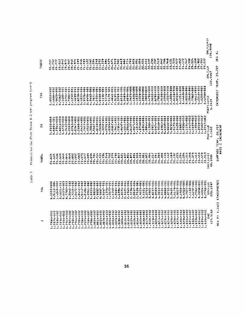
in the previous cards as uniform over the tank. X, cm (1-10); heat
flux, W/cm Z (ll-Z0).
The data deck listing, Table 5, shown on the following pages
shows the input for the Plum Brook B-2 test case with column numbers
u_ed in each case.
Table 2 Input data for the Plum Brook B-2 test comparison.
(1 -10) (1 l-Z0) (Z1-30) (31-40) (41-50)
45.0 152.4 502.93 183.64 441,25
980-67 0-05 5-0 50.0 I I
1.12616 300o0 1,40 /
2.0 NR_'(if used)
32

Table 3 Parahydrogen
kinematic viscosity data.
(,-s) (9.1s)14,000 250.7£-614,500 234,1E'615,000 221-3E-615,500 207,3E-616,000 197.5E-616,500 185.6E'617.000 177.7E-617,500 168,5E-618.000 160,5E-618.500 153,8E-619,000 147,0E-619,500 141,3E-620.000 135o4E-620,500 130,6E-621,000 125.3E-621,500 120,6E-622,000 116,1E'623,000 108,1E-624,000 100,8E-625.000 73,5E-626,000 87.2E-626.500 84,1E-627.000 81.0E'627,500 78.1E-628,000 75.2E-628-500 72-4E-629.000 69.6E-629.500 67.0E-6
30,000 64,9E-6
30.500 61,2E-6
31,000 58,1E'631-500 55.7E-632.000 51,9E-6
32.500 47.5E-632,700 43,9E-6
T able 4 Heat flux input data for the
Plum Brook B-2 test comparison
, ,(,z,-lo) ,(_!-zol ,0.0 0,031666183.64 0,031666
18.4.0 0,0036618
502,93 0,0036618624,89 0.0036618
33

Output values are shown in the printout on the following pages.
(Table 5). After listing (optional) the main calling program and the
s_veral sub-programs, the input data is listed in the order shown. The
mass of vapor present in the ullage space at time t=0 is also shown.
Note that PS has been truncated to two decimal places, for printing
only; also that gamma has been converted to radians.
A table of some property values for parahydrogen follows, both
at i. 50 arm and at pressure PS. Next is a summary line giving the
thickness,DELTAL, of the liquid stratified layer, thickness, DELTAV,
of the ullage stratified layer, and the time for these stratified layers
to develop.
Prior to the first tabulation of temperatures in the stratified
layers is a table giving the heat flux input values and the constants, AQ
and BQ, used in the linear fit established between successive points.
Boundary layer parameters at the bottom of the stratified layer are
then listed, velocity parameter and thickness for both the liquid and
vapor regions. Then follows a table of locations, temperature increases
and absolute temperatures through both the liquid and vapor stratified
layers.
Following this table the amount of liquid vaporized, DME, is
listed together with bracketing values used in a linear interpolation.
Next is listed the pressure existing after the time given earlier, the
surface temperature of the true liquid surface temperature gradient
and the intersection of the true liquid gradient with the gradient pre-
dicted by the tabulation above. For the vaporizing case the surface
temperature and intersect temperature will always be the same.
At this point the program increases the liquid stratified layer by
the amount DL and a new set of calculations is made. When the pressure
34

E"I..+
0
0f,..w
P,.,O_
.+S°
04-+
Ch
t.(h
C_
E--+
Ez_
CO c:3
cJ
P,O
,,4
0Z_
i-.-i,.+,;
0_ •
d:='cz,
(%1
Jeo
r_
÷
.-4
.4
_d
_w
J
I
c__J
_3 P_
-'_ ,c
Q. I_.
Z
c._Z
LtJ
_Z
a_
o_j_dl.-_.r'_
I.- k-
LI.I hi
_[Z 'S--I,IJW
0(3hl._P Z Z
,,,._ I, rJ I._
I....-
,_ P,+l
t_J +.4
h,.t_,,-.4
c::[ C:_
+,.I ¢=3bJ o
L_
X
++?_+
!
w
W
+l÷llm
• • + • l
ooooo
ggggg
cecil
P.4PIV')
_0
o
O_o
_o
P.0
TI,-
b_
w
J
t_J
Z+-+
o
t_
oo
4-
p_
J
+-o
35
O_J
G
O
E
O
NNNNNNNNNNNNNNNNNNNNNNNNNNNNNNNNNNNNNNNNNNNN )_
.......................... j_j_" _j..............................
h.
]E
W
I--
W
I--Z
I_.l--
e, lZ
I_.LU
oLUN_
_1_)
I--
36

LJ
(_Z
_,-I O_ _ _" U_ ,0 _ ,_00 _ -_ _ Ck_ _-
"D
(D
U
_0O
O_
00
ca
E
2
0
,1"5
)W ONNNNNNNNNNNNNN
5_ _7_77_77_777
ee_eeee_eet_eee
_ o000000000_00_0_ 0o_000_000_00_0
_w oooooooooo_oooo
0°eg00Jeot_leQ_
w(_)Z
b_
Wb_
W
O_
W_
O_bJ
bJ_-
O_
_J
O_
o o_ooo_ ooo
77777Y77777777
ooo_oooooo_oo_
oooooo_oo_c_oI@1@1|1@11@111
___._
ee_ee_e eee_
37

associated with a given stratified liquid layer exceeds PL the calcula-
tions are stopped and a summary of pressure, time, stratified layer
thickness, pressure rise rate, pressure change and time difference
is tabulated together with a statement that the pressure limit has been
exceeded.
Adjustment of the computer-obtained temperatures and pressures
for the heat flux through the bottom of the tank must be accomplished
manually -- if such a correction is deemed necessary. The mass of
liquid contained in the tank is obtained from the actual tank geometry,
the liquid level and the density of liquid at the starting pressure,
m =V 0 -e e e
Assuming that all of the heat goes into the liquid, the temperature rise
is then computed from qt = m C _T, which gives Z_T - q t Ae p m e C_"
linear variation of pressure with temperature is assumed and t_e
incremental pressure rise found from
aP max )Z_P = _T (_T max
For the Plum Brook B-?- test data the following values were
obtained:
Ve
3 6 3= 6. 654 m = 6. 654 x i0 cm ,
30. 034900e -- g-moilcm ,
.'. m = 23?.209 g-mol of LH g.e
q was computed previously to be 439. 6 W.
J/g-mol. K.
CP
has a value of Z0.01
38

A tabulation of the adjustment for tank bottom heat input effects as a
function of time follows. Tabulations are for the summary printout values.
Table 6. Adjusted pressure values
Adj us tment Adj us ted Adjus ted
Time, aP, P, p, p,
s ec onds arm atm atm N / c m 2
0 0 1. 12616 1. 12616 11.41
12.78 0. 0004 1. 14231 1. 1427 11.58
26.01 0. 0008 1. 15396 1. 1548 11. 70
39. 69 0.0012 1.16896 I. 1702 ii.86
53.87 0.0017 i. 1853 I. 1870 12.03
68.58 0.0021 1.20314 1.2052 12.21
83.85 0.0026 1.22155 1.2241 12.40
99.72 0.0031 1.23890 1.2420 12.58
I16.24 0.0036 1.26192 1.2655 12.82
133.47 0.0042 1.28272 1.2869 13.04
151.44 0.0047 1.30072 1.3054 13.23
170.24 0.0053 1.32514 1.3304 13.48
189.92 0.0059 1.35057 1.3565 13.74
210.56 0.0066 1.37131 1.3779 13.96
232.27 0.0073 1.40076 1.4081 14.27
39

Thus we have
Also
-5AT : 9. 461 x I0 t.
ZAP max : 2. 7824 N/cm
and AT max : 0. 83 K.
Combining the above we get
AP--5
(9. 461) (I00.83
) (z.7824) t = 0.00317 t, N/cm 2,
or 0.0000313 t, atm.
4O

A
A£
A, B, C, D
C
E
F
FB
FS
f
f/
Gr
g
L
7. 0 SYMBOLS
Zarea, cm .
Zarea of liquid :Tetted wall, cm .
coefficients in linear equations.
specific heat, J/g.K.
functional notation for specific energy, J/g,
linear equation constant.
force, gf.
buoyant force, gf.
viscous shear force, gf.
defined function.
defined function.
4
modified Grashof number, gSx q
v Zk
2acceleration field, cm/s
liquid depth, cm.
also
m
ITl, n
m
a
m.
1
Am
v
mr
mass, g.
constants in specific energy distribution function.
adjusted mass in ullage, g.
initial mass in ullage, g.
mass of fluid vaporized or condensed at liquid-vapor
interface, g.
Pr andtl number.
0 thermal energy, J.
41

q
qm
q%V
R
RC
R S
T
TB
T_
TS
t
U
U
V
X
Y
Z
Z1
heat flux, W/cm Z.
2.mean heat flux over specified tank wall area, W/cm
Zlocal wall heat flux, V_T/cm .
local tank radius, cm.
tank cylinder radius, cm.
tank radius at liquid surface, cm.
temperature, K.
bulk liquid temperature, K.
liquid temperature in stratified layers, K.
temperature of liquid affected by vaporization or
condensation, K.
time for liquid stratified layer to grow to depth _, s.
boundary layer fluid velocity parameter, cm/s.
local velocity in boundary layer, cm/s.
3volume, cm
distance from tank bottom, parallel to acceleration
vector, cm.
distance from wall, normal to acceleration vector, cm.
depth in stratified layer, cm.
depth in stratified layer over v;hich vaporization or
condensation affects temperature, cm.
42
C_
3
x/
A
6
e
0w
1
V
P
PB
PS
T_vv
CP
V
W
Greek Letters
2thermal diffusivity, cm /s.
coefficient of volumetric thermal expansion, I/K.
half angle of nose cone, rad.
thickness of stratified layer, cm.
incremental value.
thickness of boundary layer, cm.
calculated incremental change in 6, cm.
temperature rise in boundary layer, T - TB, K-
increase in wall temperature over bulk liquid, K.
variable in error function integral.
kinematic viscosity,
density, g/cm 3.
Zcm /s.
3density of bulk liquid, g/cm
density of saturated vapor, g/cm 3.
specific viscous shear force, g/cm 2.
parameter in error function integral.
Subscripts
pertains to liquid.
pertains to vapor.
pertains to wall.
43

[11
[z]
[31
[41
[5]
[61
[v]
[8]
[9]
8.0 References
I-luntley, S. C., Temperature-pressure-time relationships in a
cryogenic container, Advan. Cryog. Eng. 3, 342- 35Z (1960).
Neff, R., A survey of stratification in a cryogenic liquid, Advan.
Cryog. Eng. 5, 460 - 466 (1960).
Scott, L. E., Robbins, R. F., Mann, D. B., and Birmingham,
B. W., Temperature stratification in a nonventing liquid
helium dewar, J. Res. Nat. Bur. Stand. (U.S.), 64C (Eng.
and Inst.), No. l, 19 - ?.3 (January - March 1960).
Swim, R. T., Temperature distribution in liquid and vapor phases
of helium in cylindrical dewars, Advan. Cryog. Eng. 5,
498 - 504 (1960).
Tellep, D. M., and Harper, E. Y., Approximate analysis of
propellant stratification, AIAA Journal i, No. 8, 1954-
1956 (August 1963).
Vliedt, G. C., A numerical approach to temperature stratifica-
tion in liquids contained in heated vessels, LMSC 8-30-63-4
(November 1963).
Schwind, R. G., and Vliet, G. C., Observations and interpreta-
tions of natural convection and stratification in vessels,
Proc. 1964 Heat Transfer and Fluid Mech. Inst., pp. 5Z - 68
(Stanford University Press, 1964).
Harper, E. Y., Chin, J. H., Hines, F. L., Hurd, S. E., and
Vliedt, G. C., Analytical and experimental study of
stratification and liquid-ullage coupling, LMSC Z-05-65-I
(August 1965).
Vliedt, G. C., Stratification with bottom heating, AIAA J.
Spacecraft 3, No. 7, I142 - I144 (July 1966).
44

[lo]
[11]
[lZ]
[13]
[14]
[15]
[16]
[17]
Schmidt, A. F., Purcell, J. R., Wilson, W. A., and Smith,
R. V., An experimental study concerning pressurization
and stratification of liquid hydrogen, J. Res. Nat. Bur.
Stand. (U.S.), 65C (Eng. and Inst. ), No. 2, 81 -87
(April - June 1961).
Clark, J. A., A review of pressurization,
interracial phenomena, Advan. Cryo.
Z59 283 (1965).
stratification, and
Eng. IOM-U,
Urquhart, J. B., III, Propellant stratification and phase change,
Boeing Document No. D5-B487 (February 26, 1969).
Clark, J. A., and Barakat, H. Z., Transient natural convection
flows in closed containers, Heat Transfer Laboratory,
University of Michigan, Report No. 04268-10-T (August
1965).
Arnett, R. W., and Millhiser, D. R., A theoretical modeI for
predicting thermal stratification and self pressurization of
a fluid container, Proc. of the Conference on Propellant
Tank Pressurization and Stratification, Marshall Space
Flight Center, NASA (January 20, 21, 1965).
Eckert, E.R.G., and Jackson, T.W., AnaIysis of turbulent
free convection boundary layer on fiat plate, National
Advisory Committee for Aeronautics Report No. 1015
(1951).
Von Karman, Th., On laminar and turbulent friction, National
Advisory Committee for Aeronautics Tech. Memo No.
1092 (Sept. 1946).
Von Karman, Th., Uber laminare und turbuIente Reibung,
Zeitschrift Fur Angewandte Mathematik und Mechanik, Bd 1,
Heft 4, pp. 233 - 252 (August 19Zl).
45

[_8]
[19]
[zo]
Eckert, E. IR.G., and Drake, R.M., Jr., Heat and Mass Transfer,
Second Edition, (McGraw-Hill Book Co., Inc., New York,
N.Y., 1959).
Jakob, Max, Heat Transfer, Vol. i, (John Wiley and Sons, New
York, N.Y., 1949).
Lacovic, R. F., Yeh, F. C., Szabo, S. V., Jr., Brun, R. J.,
Stofan, A. J., and Berns, J. A., Management of cryo-
genic propellants in a full-scale orbiting space vehicle.
NASA TN D-4571, (1968).
46

Appendices
A. Mathematical Development
Development of the mathematical expressions used in this analy-
sis to determine the boundary layer descriptors, the extent of thermal
stratification, and the rate of pressure rise are based on several pre-
vious works. The development does, however, include certain methods
which are believed to be original for this problem. The translation [16j
r I
[ i
of Von Karman's original work Ll7j and the subsequent work of Eckert
[15]and Jackson were primary sources for the basic premise of relating
momentum flow, buoyancy force, viscous force, and thermal energy
in such a way as to permit determination of the boundary layer descrip-
tors such as thickness, velocity, and wall temperature.
This development assumes a finite geometry tank and axial
symmetry of both the tank geometry and the fluid behaviour. A cone-
shaped geometry is assumed which may occur over the entire height
of the tank or over only the upper portion of the tank. It is assumed
that the base of the cone is downward and that the acceleration force
field is directed along the tank axis. Nomenclature and physical
format are as shown in figures 2 and 3.
A. i Momentum-Force Balance Equations
Assuming a boundary layer flow parallel to the tank wall, an
equation relating the change in momentum flow over a differential
height, dx, to the forces acting over that same height is developed. It
is as sumed [15]that the temperature variation across the boundary
layer is given by
1/7
-1-(_) (1)W
47

and the velocity distribution by
i/7 4
u Z6 Y ) (2)u -( ) (1- ;_,
It is further assumed that the thickness is the same for both the tern-
perature boundary layer and the velocity boundary layer.
The change in momentum flow across the element is described by
]d--x (rhu) dx : -_ 2,_r 0(R-y) u dy cos Y dx . (4b)
A viscous shear force acts parallel to the wall and opposite to the
direction of flow,
2_RF =- m dx (6a)
v wCOS¥ '
_nd a vertical buoyant force has a component parallel to the wall of
6
F B = 2rrg cos Y .,o[(PB- p) (R- y) dy dx (5a)i
Equating the forces acting to the change in momentum flow:
dxd Z,-rcos p(R-y)u Z dy dx
[ S ]-- 2_ g cos 3 ( taB - P ) (R - y) dy dx-TW
O
2rrR
cos Ydx. (3a)
48

Since small temperature differences are encountered, we may say
P/PB _ I , except for algebraic differences such as occur in the buoyancy
- 8 . This results interm. In the buoyancy term, we let 0B P _ :3PB
i,:] /o__ 2 wdx PB (R-y) u dy _- oBBg 8 (R-y) dy- cos2 "{ . (3b)
Evaluating integrals gives
d__ [[PB - 0.0065393dx (0. 052315 R6 U 2 52 u 2 )]
: pBSg (0. 125 R6 8 - 0.033333528 ) -W W
T RW
cos Z Y• (3c)
Performing the indicated differentiation, this becomes
2 6 dU U Z
0. 052315 0 U(I - --) + (i - --B 8R 7-
g0B68 7\V (% W
(1 - 0. 26667 ---) -COS 28 6li
6 d6
4R ) dx +U 2 dRJR dx
(3d)
49

Neither _ or T in this equation are known at this point.
w [18, p_.ge t43]Blasius correlation , we obtain
Using the
1/4
_ -- 0"0228 PBU2 (U v)w 6cos T (14)
[18,Likewise, 6 can be determined by combining the Reynolds analogy
page Z03] wwith the above Blasius correlation plus a correction term by
Golburn for Pr variation [19'r page 5Z1; 18, page 324] This combination
gives,
2/3
e _- qrnPr (U6cos y)w 0. 0228 c PB U v
1/4
(]5)
Note that qm is used for the heat flux term since @ should reflect thew
total heat flux pattern below the plane under consideration. Introducing
these terms,
6 dU U 2 6 d 6 U 2 dR ]0.052315 P B 2U{1--_-_-) --_ + -_- (1 - 4--R } _+ R dx JgBqmPr2/3 1/4 1/4 1/4U7/46 cos _ 6 0. 0228 PB v
1/4U3/4 (1 - 4/15 --£ ) - 65/4 9/40. 1 824 x; cos "_
(3e)
5O
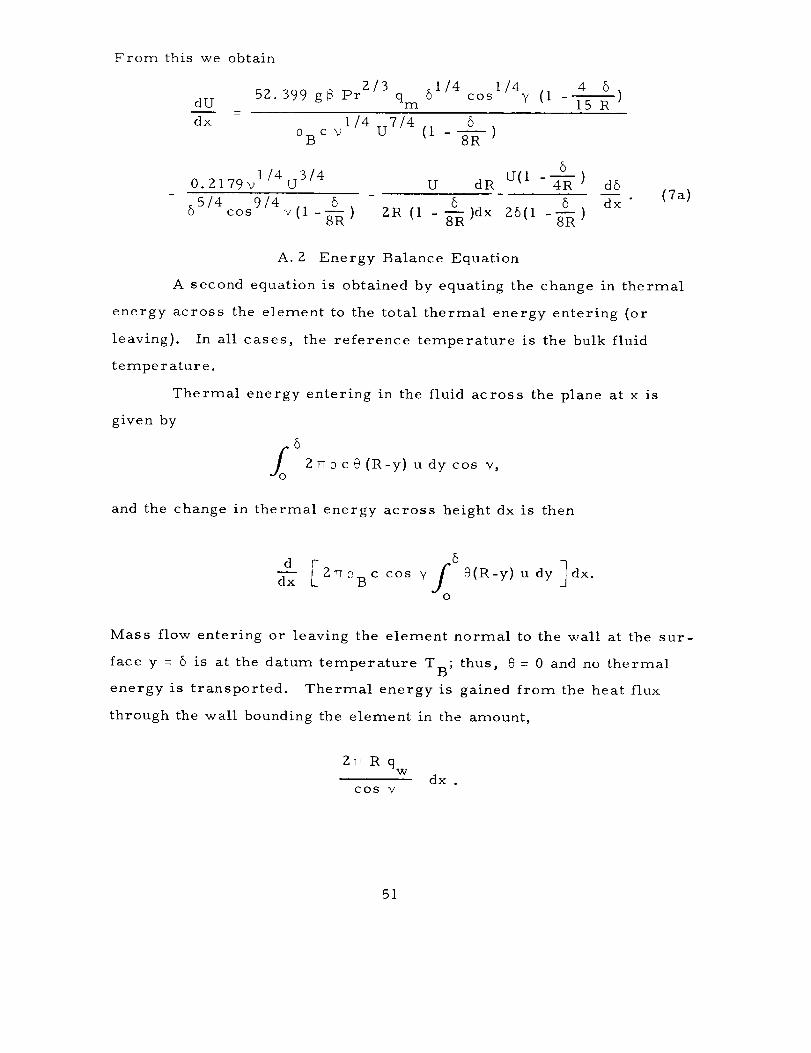
From this we obtain
dU52 399 g_ Pr g/3 I/4 i/4 4 5
• qm 5 cos V (I 15 R
dx 1/4 U7/4 50 B c v (1 - S--R- )
0.Zl79vl/4u 3/4 U dR U(l - 54---_)
55/4 9/4 _R - _R _Rcos v(1 - ) Z1R (1 - )dx g6(1 - )
d6
dx " (7a)
A. Z Energy Balance Equation
A second equation is obtained by equating the change in thermal
energy across the element to the total thermal energy entering (or
leaving). In all cases, the reference temperature is the bulk fluid
temperature.
Thermal energy entering in the fluid across the plane at x is
given by
6
fo Z_ c@ (R-y) u dy cos V,
and the change in thermal energy across height dx is then
d[ S6d'-_ 2_PBC cos V
O
@(R-y) u dy ] dx.
Mass flow entering or leaving the element normal to the wall at the sur-
face y = 5 is at the datum temperature TB; thus, @ = 0 and no thermal
energy is transported. Thermal energy is gained from the heat flux
through the wall bounding the element in the amount,
Z_RqVV
dx .cos V
51

Equating these amounts,
integration results in
setting P = P B' and performing the indicated
@ U6 (0. 03663 R- 0 004785 6{ix w
R qw dxdx = . (16)
c _ cos 2 yB
Substituting for @ and rearranging gives
d[-- RqmUdx
Differentiating,
_ U 1/4 59/41/4 55/4 0. 1306 qm ]
collecting terms and solving for
1/4
V qw R
i. 6066 Pr2/3
COS
9/4
(16a)
d6/dx yields
d6
dx
1/40. 4979v qw 4 5 5
- (1 -0. 1306 _- )2/3U1/461/4 9/4
cos Y 5qm
dq m
dx
45
5R
5(1 - O. 2352 -_- )
ll
I o5u(1-0.235z_)
(8a)
52
A. 3 Gross Energy Balance Equation
Energy enters the boundary layer over the entire tank wall and
is carried upward by the boundary layer• We assume that all energy
entering stays in the boundary layer; therefore, the rate at which energy
is carried by the boundary layer across any horizontal plane is equal to
the rate at which energy is entering the boundary layer below this plane,
thus : 6
ZT_ ;_B c cos "/l @ (R-y) udy = qmA(X) , (17)-Io
where the plane is located a distance x above the tank bottom.
Evaluating the integral and substituting for @ results inW
I. 6066 Pr 2/3 RU I/4 65/46 A (x)
i/4 (I-0. 1306 R ) = 5/4v 2rr cos "C
Solving for U,
U z
1/4 4
v A(x) ]Z/3 65/4 6 5/4 "I0. 095 Pr R (I-0. 1306 _-) cos "¢
(17a)
(9a}
A. 4 Solution of Equations
The above developed equations are of the form:
53

dU d6-- = A(U, 6,x) + B(U, 6) dx ' (7)dx
d6 _ C(U, ,5,x)+ D(U, 5) dU , (8)dx dx
and
u = u(8,x). (9}
Input parameters such as tank geometry, fluid properties, and
heat flux to the tank are required in all these equations. Solution of
the above equations is accomplished by a Newton's method iterative
process. A value for 5 (=51) is assumed and a corresponding value for
U 1 determined from equation 9a. These paired values for Uland 61
are then used in equations 7a and 8a to evaluate dU/dx and d6/dx. An
incremental change in x, Z_x, is then made and, using the same 5 a newAU dU
value U Z is found, then AU = U Z-U I. A term defined as fl - z_x - dx
is then determined. 61is now increased by an increment Z_6 = Axdg/dx,
a new set of values for U and dU/dx is calculated and an fz determined.
fz - flThe value f_ - is now found and an algebraic addition to the
A8
initial 6 1 made of the amount - fl/f _. This new value for 6 is then
used to initiate a new series of calculations. When I fll approaches
zero within some predetermined vaIue, then the corresponding values
for 6 and U are taken as the true values.
A. 5 Growth of Stratified Layer
At any plane, the volume flow rate across that piane in the
boundary layer is given by
54

z
6
2_cos Y(iR-y) udy.zO
grT(0. 1464R_},U- 0. 0Z7Z362U) cos _?. (IS1
Since V At =TR 2 Z_x , we solve for the time increment
R
_t -- 5 AZ,
0. Z9275U(I-0. 1860 _--) cos Y
(19)
By making Z_Z sufficient]y small and summing the time increments,
n
the time, t = >-_At, for the stratified layer to grow to any thickness,n
- _-_gZ,can be calculated°
The above developed equations apply to both the ullage volume
and the liquid volume.
A. 6 Temperature Distribution
During time t, thermal energy in the amount qmA£t has
entered the liquid and will appear in the liquid occupying the stratified
layer. The question to be answered then becomes, how is this energy
(as revealed by temperature) distributed in the stratified layer?
55
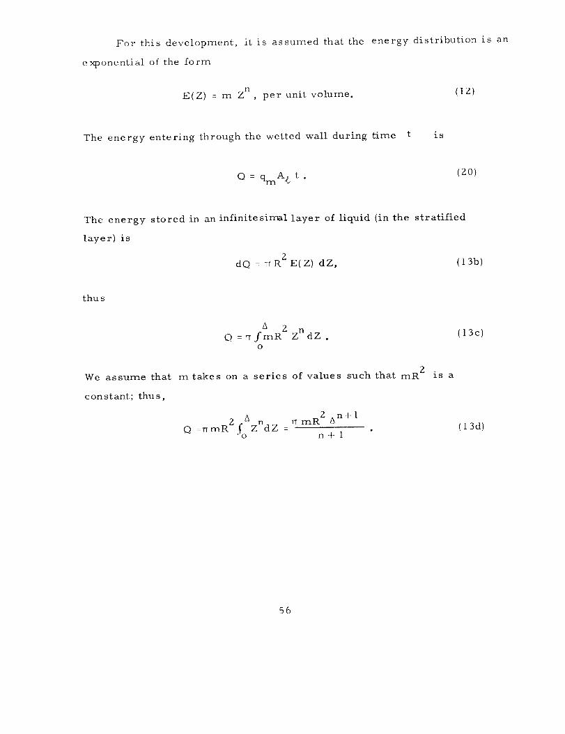
For this development, it is assumed that the energy distribution is an
exponential of the form
n
E(Z) - m Z , per unit volume. (12)
The energy entering through the wetted wall during time t is
Q = qmA£ t .(20)
The energy stored in an infinite sirr_l layer of liquid (in the stratified
layer) is
2dQ = vR E(Z) dZ, (13b)
thu s
A 2 Z nO =_fmR dZ .
O
2We assume that mtakes on a series of values such that mR
constant; thus,
is a
(13c)
f° 8 2 An+l2 _ rr mR
Q =TTmR ZndZ = (13d)n + 1
56

Combining IBd and gO, we find that
ql A£ t (n+l)ri-i -- •
Z n+l7 R 3
(21)
and therefore that
dQ qInA£ t (n+l)( Zc-_-)n:: A dZ. (13e)
Also, from the temperature of the layer:
: R 2dQ rT 0 c 0 d Z . (22)Z
Equating these expressions, we determine that,
0 qmA tn,(z): __ (23)Z 2
T_R p c A A
O thus represents the temperature pattern over the height of theZ
liquid stratified layer. The value for the exponent n is determined
empirically and has been assigned the value 2 for most of the calculations
performed. Experience has shown that the pressure rise rate is not
particularly sensitive to the value chosen for the expot-_(_l_.t.
57

The temperature pattern in the ullage space is determined by a
different method. In the ullage space, the stratified layer depth,
corresponding!4 t,_the time t found for a particular depth of liquid
stratified layer, is divided into small vertical increments. All of the
energy entering through the ullage sidewall during the incremental time
it takes for the uppermost increment to develop due to boundary layer
flow is assumed to be uniformly distributed in this increment. Energy
entering the ullage sidewall below this first increment d11ring the incre-
mental time to develop the next layer is evenly divided between the
first and second layer increment; during the next time increment, the
energy is evenly divided among the top three layers, then the top four, etc. ,
continuing in this manner until the entire depth of the stratified layer
has been covered. In addition, each layer accumulates all of the energy
entering the sidewall area it is exposed to from the time the stratified
layer depth includes that layer until the total stratified layer depth (_v)
is reached. Temperature in each layer is then obtained from the
equation
E
e = Zv (24)
Z v R2 .rTP c &ZV
A. 7 Ullage Mass Determination
Mass contained in the ullage space is obtained by a numerical
integration. At any specific point in time, the mass contained in the ullage
volume below the stratified layer is given by
(25)ml -- 0 Vs "
58
In the stratified layer, a numerical integration is conducted with each
of the increments containing a mass
where the density,
ture.
2
ZXm = =R c.{a2Z)__ Z_Z , (Z6)V
::, is a function of pressure and the local tempera-
.... ass contained in the ullage at t = 0 is given by
m. = 0 V , (27)1 S U
where Ps is the saturated vapor density at the initial pressure
A. 8 Liquid-Vapor Interface Equilibrium
At time t = 0 it is assumed that the temperature of both liquid
and vapor is uniform at the saturation temperature corresponding to
the existing ullage pressure. The initial vapor mass contained in the
ulIage space is determined by the methods outlined in section A. 7. At
time t l, corresponding to the growth of the liquid stratified Iayer to
depth _1 and the accompanying growth of the vapor stratified layer to
depth _VI' temperature gradients are computed for both the liquid and
vapor phases by the methods of section A. 6.
Determination of the ullage pressure begins by assuming an
ullage pressure corresponding to the saturation pressure for the tem-
perature existing at the liquid surface. With this pressure and the
previously established uIlage space temperature gradient, a mass con-
tained in the uIlage is determined. This calculated new ullage mass is
then compared with the ullage mass at time t = 0; if the new" mass is
larger than the initial mass, then the usual situation of liquid vaporization
is required; if the calculated mass is smalIer, then condensation of some
vapor must occur in order to achieve equilibrium between the ullage space
and the liquid surface. In the unlikely case of the new mass being equal
59
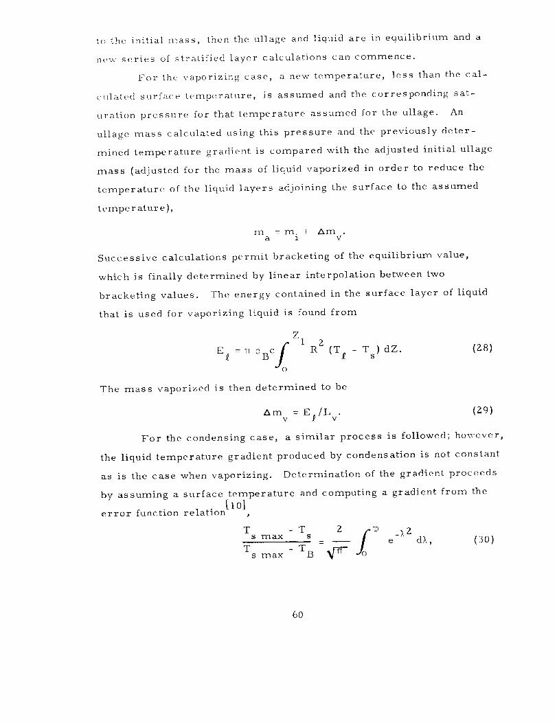
t(_the initial mass, then the ullage and liquid are in equilibrium and a
new series of stratified layer calculations can commence.
For th(_ vaporizing case, a new temperature, less than the cal-
culated surface temperature, is assumed and the corresponding sat-
uration pressure for that temperature assumed for the ullage. An
ullage nlass calculated using this pressure and the previously deter-
mined temperature gradient is compared with the adjusted initial ullage
mass (adjusted for the mass of liquid vaporized in order to reduce the
temperature of the liquid layers adjoining the surface to the assumed
temperature),
m -m. _ Ama 1 v"
Successive calculations permit bracketing of the equilibrium value,
which is finally determined by linear interpolation between two
bracketing values. The energy contained in the surface layer of liquid
that is used for vaporizing liquid is found from
Z
fo''E = rl 0BC R (T_ - Ts) dZ.
The mass vaporized is then determined to be
(Z8)
Am = E /L . (g9)v f v
For the condensing case, a similar process is followed; however,
the liquid temperature gradient produced by condensation is not constant
as is the case when vaporizing. Determination of the gradient proceeds
by assuming a surface temperature and computing a gradient from the[10]
error function relation
dX, (30)T - T Z i_ _X z
s max s_ e
T - T Bs max
6O

Zwhere :_ -
aparticular iteration.
be negative since TS
T is the assumed surface temperature for as m a×
Ef is calculated as before (note that Ef will now
> Tf and therefore Am will be negative). TheV
integration is carried only to the depth where T = Tf s"
Adjustments to the ullage pressure for the thermal energy enter-
ing the tank bottom are made for each pressure calculation step by a
manual calculation. It is assumed that all thermal energy entering is
uniformly distributed in the liquid, i.e.,
_t : PB c Ve AT,
where V is the volume of liquid in the tank. Thuse
AT -- _t# c V
B e
Pressure is assumed to be a linear function of temperature over the
small interval considered. The maximum pressure difference and
the corresponding liquid surface temperature difference are used to
establish a AP as a function of AT, thus:
AP = AT
Apmax
ATm ax
Substituting we have
AP
AP = q max t.e c V AT
B p e max
This value is added to each pressure in the summary using the
corresponding value for t.
61

B. Computer Program
A computer program has been written to solve and combine solu-
tions of the various equations developed earlier for the primary purpose
of predicting the pressure history of a closed liquid hydrogen tank. The
program consists of a main calling program, plus 26 subprograms,
together with some standard library routines. Development and pre-
dominant use of this program have been accomplished using a Control
Data Corporation _:_(CDC) 3600 computer; verification runs have been
made on an International Business Machines_(IBM) 360/65 computer.
Writing of the program was aimed at permitting the most general
input so that external parameters can be readily varied. Circumfer-
ential symmetry was assumed in the mathematical development and
must be maintained. Variables which can be inserted include axial
heat flux variations, tank geometry (i.e., radius, height, nose cone
slope), fluid properties, starting pressure, maximum pressure, liquid
quantity, and local acceleration force. When the nose of a tank is
tapered, the shape is approximated with a cone.
A brief description of the functions of the main calling program
and the subprograms is presented in the order that they would appear in
the deck. Listings of the program and the nomenclature of the important
variables are also included.
B. 1
RAVE
the correct order,
Program Description
This is the main calling program; it calls the subprograms in
detects when the pressure limit is exceeded
* Precise specification of the computer employed has been necessary
to make the description sufficiently meaningful. Identification of this
computer or its manufacturer by the National Bureau of Standards in no
way implies a recommendation or endorsement by the Bureau.
62
and prints out a summary of the results. Input required by the program
consists of 40 cards containing fluid properties, plus four cards contain-
ing tank geometry, heat flux, initial condition, limiting conditions, and
exponent to be used for liquid temperature variation.
The general calling sequence of RAVE is MASSS, PROPERTY,
DTL, DTEMPV, THETAL, THETAV, and MASSC. This sequence is
used repetitively starting with an increment, _, of liquid stratified
layer thickness and successively increases this thickness by the same
increment until the ullage pressure exceeds the pressure limit estab-
lished as part of the input data. The printed summary includes the
stratified layer thickness, elapsed time, tank pressure, pressure rise
rate, pressure difference, and time difference.
Subprograms
MASSS
Calculates the initial mass of vapor in the ullage volume under
the assumption that the vapor is saturated at the initial pressure. Sub-
program I_INDD is called by MASSS to determine the vapor density.
FINDD
Calculates the density of parahydrogen when given the pressure
and temperature. An initial estimate of density is needed when saturated
conditions exist in order to guide the result toward the liquid or vapor
value as desired. Note that this subprogram is for parahydrogen only;
if another fluid is used, then a different program will be required.
PROPERTY
Uses input cards of temperature and viscosity to calculate liquid
and vapor properties for use by other subprograms.
63

DTL
Calculates the time for the stratified layer to occupy a specified
thickness, /i. Calls subprogram ULIQ for use in calculations.
ULIQ
This subprogram calculates the liquid boundary layer thickness
and a velocity parameter. It calls DQML,
use in the calculation.
DQML
Calculates the mean heat flux, qm'
UCALCL and DUCALL for
over the tank wall below
location x and the rate of change of qm with height at x, i.e., dqm/dX.
q is drawn into the program from common via the values for the con-W
stants in the linear equation for qw (see QWL).
UCALCL
Calculates the velocity parameter U when given a boundary layer
thickness, 5. Used in the iteration procedure of DTL.
DUCALL
Given a paired set of values for U and 6 (from UCALCL) this
subprogram calculates a value for dU/dx. QWL is used in this sub-
program.
OWL
From the set of heat flux values given as input data, this sub-
program fits a linear function between adjacent locations. Where a
change in heat flux occurs, and at the liquid-vapor interface, a finite
distance must separate heat flux input values, i.e., the heat flux at
any specific location must be unique.
64
DTEMPV
Calculates the time for the ullage space stratified layer to reach
a certain depth. Determines a stratified layer thickness corresponding
to the time calculated in DTL by an iteration procedure• Calls UVAP
and INTEGRAT.
UVAP
Calculates, via an iteration procedure, a consistent set of values
and 6 . Uses subprograms DO.MV, UCALCV, and DUCALV.V
for UV
INTEGRAT
Uses the Newton-Cotes numerical integration method to integrate
over a set of values using a minimum of seven evenly spaced points.
DQMV
Calculates values for the mean heat flux, qmv' and the rate of
change of qmv with height, dqmv/dX. Uses output of QWV.
UCALCV
Calculates a value for the velocity parameter, U , in the ullageV
space when given a boundary layer thickness, 6V
DUCALV
Calculates the rate of change of U with height, dU /dx, whenV V
given a paired set of values for U and 6 . Uses QWV in the calcula-V V
tions.
QWV
Uses the same set of input data for heat flux as QWL and supplies
a linear fit between successive values.
THETAL
Determines the temperature distribution in the liquid stratified
layer based on the assumed exponential variation of specific energy.
The exponent used is part of the input data. Subprograms ULIQ, DOML,
and INTEGRAT are used.
65

THETAV
Determines the temperature distribution in the ullage stratified
layer by the method described by equation Z4, appendix A. 6. Uses
PTCP in the calculations.
PTCP
Calculates specific heats for either the liquid or vapor state using
input data from CSUBP or CSUBV. Values produced are for para-
hydrogen only and substitution must be made if another liquid is used.
MASSC
Determines equilibrium value for liquid vapor interface. Sub-
programs VP, MASSU, INTEGRAT, ERF and DMF are used. Iterates
on a final value that assures pressure and temperature equilibrium at
the interface as well as a mass and energy balance.
VP
Calculates a saturated vapor pressure corresponding to a given
temperature. Gives values for only parahydrogen as written; a cor-
responding program would be needed for a different fluid.
MASSU
Calculates the mass contained in the ullage volume when given a
temperature distribution and a pressure. Uses subprograms FINDD
and INTEGRAT.
ERF
Calculates values of the error function for values of the argu-
ment supplied by the using subprogram. Used by MASSC to treat the
condensing case.
66

DMF
Calculates the latent heat of vaporization at an average pressure
between the pressure of the previous step and the current try. Used in
MASSC to compute the mass vaporized or condensed. Values are for
parahydrogen only; a corresponding program would be needed for adifferent fluid.
CSUBP
A tabular set of data of constant pressure specific heats for
parahydrogen only. Used by PTCP.
CSUBV
A tabular set of data of constant volume specific heats for para-
hydrogen only. Used by PTCP.
In addition to the above described programs, certain other library
programs are used in various of the subprograms. These are:
TANF
Returns the tangent of an angle when given that angle.
COSF
Returns the cosine of an angle _,hen given that angle.
SORTF
Extracts the square root of a number.
EXPF
nReturns the value e when given n.
67

B. Z Program Nomenclature
Symbol
AL
AQ
AV
BETAL
BE TAV
BQ
COSA
COSG
CPL
CPV
DELTAL
DELTAV
DENL
DENV
DPDRL
DPDRV
De s c ription
Thermal diffusivity, liquid,Z
cm /S .
Constant in linear equation for qw"
Thermal diffusivity, vapor, cm2/s.
Thermal coefficient of volumetric expansion,
liquid, I/K.
Thermal coefficient of volumetric expansion,
vapor, I/K.
Constant in linear equation for qw"
Cosine of GAMMA.
Constant pressure specific heat, liquid, J/g-mol-K.
Constant pressure specific heat, vapor, J/g-mol. K.
Stratified layer thickness, liquid, cm.
Stratified layer thickness, vapor, cm.
3
Specific volume,
Specific volume,
saturated liquid, cm /g-mol.
3saturated vapor, cm /g-mol.
Value of (bPlh P)T'
31saturated liquid, atm. cm g-mol.
Value of (?P/? _%,
3saturated vapor, atm. cm /g-mol.
68
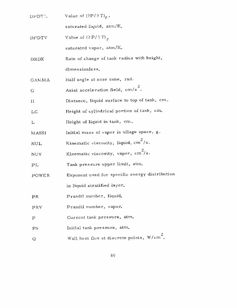
DPDTL
DPDTV
DRDX
GAMMA
G
H
LC
L
M ASS 1
NUL
NUV
PL
POWER
PR
PRV
P
PS
Q
Value of (_P/_T)p,
saturated liquid, atm/K.
Value of (%P/?T)P
saturated vapor, atm/K.
Rate of change of tank radius with height,
dimen sionle s s.
Half angle at nose cone, rad.
ZAxial acceleration field, cm/s
Distance, liquid surface to top of tank, cm.
Height of cylindrical portion of tank, cm.
Height of liquid in tank, cm.
Initial mass of vapor in ullage space, g.
Kinematic viscosity, liquid, cmZ/s.
Kinematic viscosity, vapor, cm2/s.
Tank pressure upper limit, arm.
Exponent used for specific energy distribution
in liquid stratified layer.
Prandtl number, liquid.
Prandtl number, vapor.
Current tank pressure, arm.
Initial tank pressure, atm.
Wall heat flux at discrete points, W/cm 2.
69

OW
RC
RHO
RHOV
R
RS
SL
SV
TAMB
TANG
TB
TDL
TDV
TH
THV
TIME
Linearized value for wall heat flux over
tank height, W/cm Z.
Cylindrical radius of tank, cm.
Density used during current calculation,
liquid, g/cm 3.
Density used during current calculations,
saturated vapor, g/cm 3.
Local tank radius, cm.
Tank radius at liquid surface, cm.
Entropy, saturated Iiquid, J/g-mol-K.
Entropy, saturated vapor, J/g-mol-K.
Ambient temperature, K.
Tangent of GAMMA.
Bulk temperature, liquid, K.
Local temperature increase in stratified layer,
liquid, K.
Local temperature increase in stratified layer,
vapor, K.
Boundary layer thickness,
liquid, cm.
Boundary layer thickness,
vapor, cm.
Current time to achieve DELTAL, s.
7O

TSAT
U
UV
X
ZINC
Z
ZV
Saturation temperature corresponding to P, K.
Boundary layer velocity parameter, iiquid, cm/s.
Boundary layer velocity parameter, vapor, cm/s.
Vertical distance variable, cm.
Number of increments of DELTAL and DELTAV.
Vertical distance in stratified layer,
liquid, cm.
Vertical distance in stratified layer,
vapor, cm.
71

B. 3 Program Listing
IIII
6OO
II12
13
14
16
17
PROGRAM RAVE
DIMENSION TABSL(IOII,TABSV(IOII,ZY(IOI)
1 COMMON AL,AQ(1OO),AV,BETAL,BETAV,BQ(1OOI�COSA,COSG,CPL(20)'CSL'1 CPV(20),CSLA,CSV(20),DELTAL(501,DELTAV(50)�DENL(20),DENVI20)'DL'
2 DPDRL(20),DPDRV(20),DPDTL(20),DPDTV(20),DRDX,DVP,FP,G,GAMMA,H,
5 I,IDX,IU,IXV,IZ,JERROR,JTR,KB,KD,L,LC,MASS�MASSI,NPT,NTR'NUL,
L_ NULA,_!UV,NX,P,PA(50),POWER,PR,PRV_PT(20),Q(100),QW,RtRC,RHO,
5 RHOV,RS,SL(20),SLC,SV(20),TAMB,TANG,TB,TDL(101),TDV(IO1)'TH,THV,
6 T1ME(50),TSAT(Z0),U,UV,X,XB(IOO),Y(IO1),ZI101),ZINC,ZV(1OI)
2 FORMAT(1OE8,O/2EIO,O)3 FORMAT(4FIO,O)
4 FOR_4AT(SFIO.0)
5 FORMAT(4FIO°O,gX,I1)REAL L,LC,MASS,NUL,LV,NUV
NTR = i
NPT=I
JTR = 1READ(5,2)(PT(!),DENLII)tDPDRLII),DPDTLII},DENV(II_DPDRVII)'DPDTV(I
1) ,SL(I ),SV(1),TSAT(1)tCPV(1),CPL(1),I=I,20 )
8 READ(5,4) GAMMA, RC9 LC, L, H
o READ(5,5) G,QW,DL,ZINC,NR
10 READ(5,3) PSi TAMBt PL
READ (5,1111) POWER
FORMAT(FIO,O)GAMMA= 3,1415926535*GAMMA/180,O
JJ=ZINC
NPTS=JJ+IJERROR = 1
KB = 1
KD = 1
DO 600 II=1,50
DELTAL(I)=O,0DELT LO = O,ODELT VO = 0,0
DVP = 0,0
KR = 1P : PS
CONTINUEWRITE(6,171) DL,PL ,ZINC,PS,TAMB
171 FORMAT(18X,2HDL,17X,3HPL ,16X,4HZINC,17X,2HPS,16X,kHTAMB/5F20,2)
172 FORMAT(10X, 91H GAMMA RC
ILC L H /F20.5,4F20.2)
173
1112
18
19
180
2O
190
WRITE(6,172) GAMMA,RC,LC,L,H
WRITE(6,173) G,QW
FORMAT(16X,IHG,2OX,2HQW/ 2F20°3)
WRITE (6,1112) POWER
FORMAT(12X,12H POWER : ,FIO.4)
CONTINUE
CALL MASS S
WRITE(6,180)
FORMAT(5OX,16HMASS S
CALL PROP TY
FORMAT(5OX,2OHPROPERTY
WRITE(6,190)
INCREMENT)
INCREMENT,I)
72
21 GO TO 2722 DO 24 I = 2,20
23 IFIPT(I)-P) 24,25,25
24 CONTINUE
25 CALL PROP TY210 FORMATI5OX,2OHPROPERTY INCREMENT 2)
WRITE(6,210}
27 CALL DTL
GO TO (221,42)_JERROR
221 WRITE(6,220)
220 FORMAT(5OX,13HDTL INCREMENT)
28 CALL DTEMP VGO TO (231,_2),JERROR
231 WRITE(6,230)
230 FORMAT(5OX,ITHDTEMP V INCREMENT)
29 CALL THETA LGO TO (241,42),JERROR
241 WRITE(6,240)
240 FORMAT(50X*lTHTHETA L INCREMENT)
30 CALL THETA V
GO TO (244,42)gJERROR
244 GO TO (245,251),NPT
245 IF(NX,LT,3) GO TO 251WRITE(69500)(XB(JJ),Q(JJ),AQ(JJ )tBQ(JJ )_JJ=I_NX)
500 FORMAT(16X, 2HXS,20Xt2HQ ,16X_2HAQ,19X,2HBQ//(2X,2F20,5,2E20o4)
1)250 FORMAT(5OX,17HTHETA V INCREMENT)
251 WRITE{6,250)
NPT=2
WRITE(6,502)
502 FORMAT(14X,1HZ_15X93HTDL,13X,SHTABSLt14X,2HZV,14XP3HTDVt
1 13X,SHTABSV /)
DO 505 JJ=I_NPTS
TABSL(JJ) = TB + TDL(JJ)
TABSV(JJ) = TB + TDV(JJ)
504 ZY(JJ) = L + Z(JJ) - DELTAL(KB)
505 WRITE(6,510)ZY(JJ)_TDL(JJ),TABSL(JJ}tZV(JJ)tTDV(JJ),TABSV(JJ)
510 FORMAT(2(&Xt2EI6°4,SX_FlO.3))
31 CALL MASSC
GO TO (261,42)_JERROR
260 FORMAT(50X,16HMASS C INCREMENT)
261 WRITE(6_260)
33 JTR = 2
35 IF(KR.GT.I) GO TO 39
36 PAO = PS
PA(KR) = P
IF(P.GT.PL) GO TO 42
TIMEO = 0.0
37 KR = 2
38 GO TO 22
39 PA(KR) = P
IF(P.GT.PL) GO TO 42
40 KR = KR+I
41 GO TO 22
73

a2 WRITE(6,45)KO = 0
WRITE (6,a6) PAO,TIMEO,DELT LO,DELT VO,KO
43 WRITEI6,46)(PA(K),TIME(K),DELTAL(K }_DELTAV(K ), K ,K=I,KR)
45 FORMAT(IH196X,SHRRESSURE,IIX,4HTIME,9X,6HDELTAL_gX,6HDELTAV,9X,
i 1HK/5X,IIHATMOSPHERES,8X,7HSECONDS_5X,IIHCENTIMETERS,qX,11HCENTI
2METERS/)
46 FORMAT( aE15.5,I10}
47 _RITE(6,55)
DELPA = PA(1}-PAO
C'ELT21 = TIME(Ii-TIMEO
PRISEA = DELPA/DELTB
IDA = i
WRITE(6,54) PRISEAtDELPA,DELTB,IDA
48 DO 59 ID = 2,KR
a9 IF( KR.GT.SO) GO TO 59
50 DELP = PA(ID) - PA(ID-1)
51 DELT = TIMEIID) - TIME(ID-1)52 PRISE = DELP/DELT
53 WRIlE(6,54) PRISE,DELP,DELT,ID
54 FORMAT (3E30.5,120)55 FORMAT(lHO,15X,18HPRESSURE RISE RATE,12X,19HPRESSURE DIFFERENCE,
1 13X,15HTIME DIFFERENCE,13X,9HINCREMENT/22X,THATM/SEC,24X,3HATM,
2 28X,3HSEC/)
56 WRITE(6,57)
57 FORMAT{3X, 59HTANK PRESSURE HAS EXCEEDED UPPER LIMIT, SCRATCH ONE
1 CENTAUR)
58 GO TO 61
59 WRITE(6,60)
60 FORMAT(SX,37HINCREMENTS OF PRESSURE RISE EXCEED 50)
61 IF(NR.EQoO) GO TO 62
NTR=NTR+I
NPT = 1
GO TO 8
62 CONTINUEEND
74

SUBROUTINE MASS S
THIS ROUTINE COMPUTES MASS CONTAINED IN ULLAGE GAS
SPACE WHEN NO TEMPERATURE GRADIENT EXSISTS
1 COMMON AL,AQ(100),AV,EETAL,BETAV,BQ(10OI,COSA.COSG,CPL(20),CSL,
I CPVI20)_CSLA,CSV(20),DELTAL(50),DELTAVISO),DENL(20),DENVI20),DL,
2 I)PCRLI20),DPDRV(29),DPDTL(20),DPDTVI20),DRDX,DVP,FPgG,GAMMA,H,3 I,IDX,IU,IXV,IZ_JERROR,JTR_KB,KD,L,LC,MASS,MASSI,NPT,NTR,NUL_
4 h/:LA,NUV,NX,P,RA(50) ,POWER,PR,PRV,PT(20) ,Q(100) ,QW,R,RC,RHO,
5 RIIOV,RS, SL (20) ,SLC,SV( 20 ) ,T#MB, TANG, TB,TDL(101) ,TDV(101) ,TH_THV,
b TIMEISO),TSATi20),U,UV,X,XBI100),YC101),ZI101),ZINC,ZV(101)
REAL L,LC,MASS,MASS1
3 DO 5 I = 2,20
4 IF (PT(I)-P) 5,6,6
5 CC#_TINUE
6 TB = FINTITSAT)
7 RHOG = (FIND D(P_O°50,TB))*0.00201572
8 COSG = COSF(GAMMA)
9 TANG = SIN(GAMMA)/COS(GAMMA)
10 IF (L.LT°LC) GO TO 14
11 RS = RC-(L-LC)*TANG
12 MASS = RHOG_3°14159*((RS**2)*H-RS*(H**2)*TANG+CC(H**3)*(TANG
1 *_2))/3,0))
WRITE(6,22) MASS
MASS1 = MASS
13 RETURN14 RS = RC
15 H1 = H
16 H = H-(LC-L)
17 MASSA=RHOG*3,14159_(IRS_2)_H-RS_(H_#2)*TP, NG+((IH_*3)_(TANG1 _'2))/3°0))
18 H = LC-L
19 MASSB = RHOG*3°14159*IRC**2)_H
20 MASS = MASSA+MASSB
21 WRITE(6,22) MASS
22 FORMAT(24X, 4HMASS /E20°4)
23 MASS1 = MASS
24 H = H125 RETURN
END
75

I
23
4
5
6
7
8
FI)NCT ION FINDD(PRES,TG,TEMP)P:PREST: TE_._P
IF(TG.NE,O,O) GO TO 6DF=(IT/!3°8031**O.31042771/26.176
IF(T°GT°IOO.) GO TO 6_F(T.GT.34.) GO TO 7
IF(P.GT°12.759)GO TO 4
IFIT.LT.13°803) T=13.803
IF(T.LT.20.268) GO TO I
V=2.00062-50.O9708/(T÷I.OO44)+O.O1748495*T
VP=IO.O**V
IF(T.LE.29.01 GO TO 2
A=T-29.0TTT=A*A*A
TF=TTT*A*A
TS=TTT*A*TTT
VP=VP+O.OO1317*TTT-O.OOOO5926*TF+O.OOOOO3913*TS
GO TO 2
VP=lO.O**I!.772454-44.36888/T+O°O2055468*T)IF(VP-P)3,6,6
D=.O417-O.OOOO154*T*T
IFIO.O695+IT-13.8031*I30.3312*EXPI-5.693/T)+IT+T)/3.)-P)5,5.8
IF(O.O695+IT-13.803)*I30.3312*EXPI-5.693/T}+(T+T}/3.)-P)5.5,7FINDD=DF "1000.028
RETURN
D=P/T/80.GO TO 8
D=IDF*I100.-T)+IT-22°)*P/8206°)/78o
R=26.176*DRR=R*RRRR=R*RRRRRR=RR*RR
X=13.803/TSSX=SQRTISQRT(X))S=D/.01544
A=T/32.976
A=A*A
A=A*A
T8=A*A
SMO=S-I°OPHI=O.O
Z=O,O
C=(((((((10,72108689-O.77025578*RRRR)*RRR-67,14588122)*RR+
1239,11305168)*R-294,2851871)*R+128,B2512808)*R-13.98447635
2)*R-2,01760851}*R
BEXP= ((((],83199451-O,94457676*R)*RR-O,24100077)*R-2,2337918
1)*R+1.96823016)
BEXP=EXP(BEXP)
B=R*(BEXP-I,142711
AEXP=EXP(-1,42684*R)
A=2,13502896*R+l.01704119*RR*AEXP
PI=(81,*R-697,)*RR
PEXP=EXP(A*SSX+B*X+C*X*X*X+Z)
76
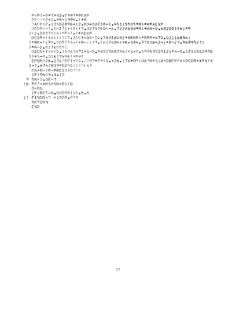
9
I0
]I
P=P I + DX-T* 82 • 0597"PE XP
DP[ =(243._R-1394, )'X-R
DADR=2. 13502896+(2.03408238-1.45115505"R) _R*AEXP
DBDR=-] . 14271+ ( ( { ( 7. 32797804-4-. 7228838"_R) *RR-O ,48200154) *R
)"-P+ !. ) *BEXP
( !.OT. 2108489- 10.78358092-,>RRRR)*RRR-470.02116854 )
65253,_) _-R-I 177 .14.07484 )*R+384. 97538424) _R-27. 9689527)
1-2.2337918
DCDR=(((I(
t_RR+1195.5
2_R-2.0176085!
DZDS=((((O.1536_O
I)_S-0.01617496)_P
DPDR=26.176_DPI+R
l+2.4742833_DZDS))
DN=D-(P-PRES)/Dr_b
IF(DN)9_9,10
DN=I.OE-7
PCT=ABS(DN-D)/D
D=DN
IF(PCT-O,O0005)]],8,8
FINDD=D _lO00eOP_
RETURN
END
72_S-0.5492768736)_,'S+0.5095350712)_S-0.1811562976
HI
2.(;597_T _(I.+26.]76_D _(OADR_SSX+DBDR_"X+DCDR_,X_-X_-X
-:,,p !- X :)
P
77

FUNCTION FINT(DtJ)i COMMOb: /_.L,AQ (100 ) ,AV, BETAL, BETAV,F_O ( 1(JO } ,COSA _COSG ;CPL (20 _ ,CSL,
1 CPVi20),CSLA,CSV(20),DELTAL(50),r)ELTAV(50),DENL(20)'DENV(20)'DL'2 DPDRL(20),DPDRV(20) ,I)PDTL[20) ,DP[)TVi2:)),DRT)X,DVP,FP,C',GAMMA,H,
3 I,IDX,IU,IXV,IZ,JERRORtJTR,KB,KD,I_,LC_r!ASS,!'!ALSSt,NPT,"4TR'NUL ,4 NULA,NUV,NX,P,PA(50),POWER,PR_PRV*PT(2{:!_ ,(_( lob} _O',,.I,R,RC,RHO,
5 RHOV*RS,SL i20) ,SLC,SV( 20 ) ,T AMB _ FA'_;6'T[_'_T DL-{]-()1)'TP'V {]*)I ) 'TH' THV'
6 TIME(50),TSAT(20),U,'JV*X,XB[IO¢"),Y(101)'Zf ],:::t),Z/,"4C,Z_(IOI)
DIMENSION PU(lO1)10 FINT =PU( I)-(PU( I )-DU( I-1 ) ) _(PT( I I-P_/(pT ( [ )-PT( [-I ) )
RETURN
END
7_

SUBROUTINE PROP TY
THIS ROUTINE COMPUTES THE FLUID
SOURCES OF CORRELATIONS AND
PROPERTIES OF SUBJECT LIQUID
TABLES USED BELOW
LIQUID PROPERTIES ' NBS REPORT 7987,RODER,WEBER AND GOODWIN
CSV 7987 AND DEFINITIOr_I
NUL AND NUV CDC R'349 DILLER
KONL COMPENDIUM AND 7987+CALCULATION
KONV COMPENDIUM + CALCULATIONSLATENT HEAT 7987+DEFINITION
1 COMMON AL,AQ(IOOI,AV,BETAL,BETAV,BQ(IOO),COSA,COSG,CPL(20),CSL,
1 CPV(20),CSLA,CSV(20),DELTAL(50),DELTAV(50),DENL(2OI,DENVI20),DL,
2 DPDRL(20),DPDRV(20),DPDTL(20),DPDTV(20),DRDX,DVP,FP,G,GAMMA,H,
3 I,IDX,IU,IXV,IZ,JERROR_JTR,KB,KD,L,LC,NIASS,MASS1,NPT,NTR,NUL,
4 NULA,NUV,NX,P,PA(50),POWER,PR,PRVgPT(20),Q(IOO),QW,R,RC,RHO,
5 RHOV,RS,SLi20),SLC_SVI20),TANB,TANG,TB,TDL(IO1)_TDV(IO1),THoTHV,
6 TIME(50),TSAT(20),U,UV_X,XB(IOO),Y(IOI),Z(IOI),ZINC,ZV(IOI)
REAl_ L,LC,MASS,NUL,LV,NUV,KONL,KONB,KONV,NUOTV,NULA,NU,P411L
DIMENSION SATTI35),NU(35)
6 FORMAT (2E8°0)
7 GO TO (R,Q), JTR
8 READ(5,6)ISATT(K),NUIK),K=1,35)
9 TTSAT = FINT(TSAT)
GO TOIlO,27),JTR10 CSL = F[NT(CPL)/2°016
11 CSLA=CSL
12 RHO = 2,016/FINT(DENL)13 DO 15 K=2,35
14 IF(SATT(KI-TTSAT)15,16,16
15 CONTINUE16 NUL=NU(K)-(NU(K)-NU(K-1))_(SATT(K)-TTSAT )/(SATT(K)-SATT(K-1))
17 MUL = NUL
18 NUL = NUL / RHO
19 NULA = NUL
20 KONL = ((1.702+O,05573*TTSAT)*10,O**(-4))_4,184
21 AL = KONL/(RHO*CSL)
22 DEL = FINT(DENL)
23 DPL = FINT(DPDTL)24 DRL = FINT(DPORL)
25 BETAL = DEL_(DPL/DRL)26 PR L = NUL/AL
SLC = FINT(SL)
27 NUOTV=8.5558*((TTSAT_*1,5)/(TTSAT+19.55))*((TTSAT+650.39)
i /(TTSAT+II75.9))_(IO.O**(-6 ))
28 RHOV = 2.016/FINT(DENV)
_2 NUV = NLIOTV/RHOV
33 KONV = (7,40*TTSAT*7,0)_(10,O**(-6))
35 ESV(1) = O°9_(FINT(CPV))/2°OI6
36 AV=KONV/IRHOV*CSV(1))
37 DEV = FINT(DENV)
38 DPV = FINT(DPDTV)
39 DRV = FINT(DPDRV)
40 BETAV = DEV_(DPV/DRV)
41 PRV = NUV/AV
WRITE(6,130)PT(I),DENL(I),DPDRL(I),DPDTL(I),DENVII),DPDRVII),MUL,
73

130
1132 FORMAT(3X_5HDPDTV,LOX,2HSL,10X_2HSV,8X,aHTSAT_gX,3HCPV911X_1HP_
1 9X,3HPRV/TE12.4)
42 FORMAT(TEIa.4,15)
142 FORMAT (8Ela.4,15)_3 FORNAF(9X,3HCSV ,gX,5HTTSAT_IIX,3HCSL,9X_5HNUOTV_IIX,3HRHO_IOX
1 ,4HRHOV,11X,3HNUL_13X,1H[)WRITE(6,132)DPDTV(I).SL(I),SVII).TSAT(I)_CPVCI),P.PRV
44 WRITE(6,43)a5 WRITEI6,42)CSV(1),TTSAT,CSL,NUOTV,RHO,RHOV_NUL.I46
IPRLFORMAT(IH0.3X,2HPT,8X,4HDENL,7X,5HDPDRL,7X,SHDPDTL,gX.4HDENv,7X,
5HDPDRV,9X,3HMUL,9X,gHPRL/SE12,4)
FORMAT ( 11 X, 3HNUV, 10 X ,z{ HKONL ,1 ] 2 X, 2 HAL,
1 3HCSV _ 12X _2HAV. 9X, 51";BETAV.gX _ 5HBETAL , 4;< _ 1HK)
a7 WRITE(6,46)A8 WRITE(6,142)NUV,KONL,Al__
50 RETURNEND
IOX ,L_HLONV, 1 lX,
KONV,CSV(]I),AV_BETAV 9BETAL ,K
_0

SUBROUTINEDT LTHIS ROUTINECOMPUTESTHE GROWTHRATE OF THE STRATIFIED LIQUIDLAYER
1 COMMONAL,AQII00),AV,BETAL,BETAV,BQ(1OO),COSA,COSG,CPL(20),CSL,i CPV(20),CSLA,CSV(20),DELTAL(50),DELTAV(50),DENLI20),DENV(20),DL,2 DPDRL(20),DPDRV(20),DPDTLI20),DPDTV(20),DRDX,DVP_FPgG_GAMMA,H,3 I,IDX,IU,IXV_IZ,JERROR,JTR_KB,KD,L,LC,MASS,MASSI,NPT,IqTR,NUL,
4 NULA*NUV,NX_P,PAI50),POWER,PR_PRV,PT(20),Q(IOO)_QW,R,RC,RHO,
5 RHOV,RS,SL(20),SLC,SV(20),TAMB_TANG,TB_TDL(Z011,TDV(IOI)_TH,THV,
6 TIMEI50),TSAT(20),U,UV,X,X_(IOO),Y(IOI),Z(IOI),ZINC,ZV(IOI)
DIMENSION FI7)
REAL L*LC,MASS,NUL,LV,NUV,KONL,KONB,KONV,NUOTV,NULA,NU
3 IDX = 1
4 B = BETAL
5 PR=NUL/AL
6 GO TO (9,57),NPT9 NX=O
10 READ (5,11) XB(NX+I),O(NX+I)11FORMAT(2FIOoO)
IF(Q(NX+I)) 13913,1212 NX=NX+I
GO TO 1013 IF(NX)I4,14,17
14 NX=3
XB(1):O,O
XB(2)=LC
XB(3)=L+H
BQ(1)=OoO
BQ(2)=OoO
BO(3}=O.O
AQ(1)=O°OAQ(2)=QWAQ(3)=QW
GO TO 22
17 BQ(1)=O°O
AQ(I}=OoO
DO 21 K=2'NXBQ(K):IO(K-1}-Q(K))/(XB(K-1)-XB(K))AO(K)=Q(K-1)-BQ(K)*XB(K-1}
2t CONTINUE22 CONTINUE
DO 25 J=2,NX[F(XB(J)6GToL) GO TO 26
25 CONTINUE26 CONTINUE
IXV=J
TIMEP=O,O
DELTAL(I}=DL
DELTAL(1)=DLGO TO 58
57 DELTALIKB)=DELTAL(KB-1)+DL
58 X=L-DELTAL(KB)IFIX,LE,L) GO TO 61
59 WRITE (6,60) X
8]_

60 X = F9,2,20H, X IS OUTOF RANGE, 1FORMAT ( 8H1FOR
JERROR=2RETURNF 4
F 3 =F(4F 5 =F(4F 2 =F(4
F 6 =F(4
F 1 =F(4F 7 =Ff4
ASS GN 63
=X+DL/2,
-DL*0.2029225757
+DL*0,2029225757
-DL_0.3707655928
+DL_0,3707655928
-DL*O.47&5539562
+DL*0,_7#5539562
TO KTR
DO 66 N=],7X=F(N)GO TO 70
63 CONTINUE66 F(N)=(R-TH*(2,0-TH/RII/(2.0*U*TH_COSA*(,1464-,O2723_TH/R))
TIME(KB)=TIMEP+(F(4)_O°4179591836+(FI3)+F(5)I*O.3818300505+(F(2)+1F(6))_O.2797053915+(F(1)+F(7))_O,129&849662)_DL/2.0
TIMEP=TIMF(KBI
X=L-DELTAL(KB)
ASSZGN 67 TO KTR
GO TO 7067 CONTINUE
RETURN
70 CONTINUE72 IF(X-LC)73,73,74T3 COSA=I,O
DRDX=O°GO TO 75
74 COSA=COSG
DRDX=-TANG
75 CONTINUE
R=RC+(X-LC)*DRDX
CALL ULIQ
GO TO KTR, (63,671END
82

C
SUBROUTTNE U LIO
1 COMMON AL,AO(1OO},AV,BETALgBETAV,BQ[IO0),COSA,COSG,CPL(20),CSL,
I CPV(20),CSLA,CSVC20)gDELTAL(50),DELTAV(50),DENLI20)_DENV(20),DL,
2 DPDRL(20),DPDRV(20),DPDTL[20),DPDTV(20I,DRDX,DVP,FP_G,GAMMA,H,
3 I,IDX,IU,IXV,IZ,JERROR,JTR_KB,KD,L,LC,MASS,MASS],NPT,NTR,NUL_
4 NULA,NUV,NX,P,PA{50),POWER,PR,PRV,PT(20},OI100),QW,R_RC_RHO,
5 RHOV,RS_SL(20),SLC,SV(20)_TAMB_TANG,TB,TDL(1011,TDV(IOI),TH,THV,
6 TIME(50),TSAT(20},U,UV,X,XB(IOO),YIIO1),Z(IO1),ZINC,ZV{101)
COMMON /VAR/NUV14, NUL14_ PRV23, PRL23, COSA54
REAL NU\/ 14, NULl4, LC_ NUL, NUV
PRL23 = PR_(2,0/3°O)NULl4 = NUL**0.25
COSA54=COSA*_1°25
GUESS FOR TH
10 THI = 0.I_X_(5°0/7°0)
30 CALL DQML(X, AREAX1, QMI_ DOMDXll
60 X2 = X + 1.70 CALL DOMLIX2, AREAX2, OM2, DQMDX2]
20 DO 170KK=1,2040 U1 = U CALC L(AREAX1, TH1)
50 DUDXl = DU CAL LIOM1, DQMDX1, TH1, UI_ X)80 U2 = U CALC L(AREAX2,THll
90 DEL Ul = (U2 - U1)/ 1.
100 F1 = DUDX1 - DEL U1110 IFIABSFIF1) - .O01_DUDX1)180,180,120
120 TH2 = THl*l°l130 U3 = U CALC L(AREAX1, TH2)140 DUDX2 = DUCAL L[OM], DOMDX1, TH2, U3_ X)
150 U4 = U CALC L(AREA X2, TH2)
160 DEL tJ2 = (U4 - tJ3]l ]°170 TH1 = TH1 - FI/I(F1 - (DUDX2 - DEL U2))/(TH1 - TH2))
WRITE(6, 300)300 FORMAT(1H1/I/II//I//19H _ _ _ _ _ _ _ _ _ 11124H U LTO DID NOT CON
1VERGE. )
WRITE (61301) X_ THI, DUDX1, DEL U1301 FORMAT( 4H X =, E20°10/6H TH1 =, E20.10/ 8H DUDX1 =, E20.10/gH DEL
1 U1 =, E20°10i1H1)
180 TH = TH1
190 U = U1IF (THIR.LT. 0.2) GO TO 200
TH = O.2*R
U=U CALC L(AREAXI_TH )
200 RETURN
END
85

10
15
20
30
SUBROUTINE DQML (A8,A,QM,DQM)
1 COMMON AL,AQ(IOO),AV_BETAL,BETAV,BQ(IOO|,COSA,COSG,CPL(20),CSL,
I CPV(20),CSLA,CSV(20),DELTAL(50),DELTAV(50),DENL(20),DENV(20),DL,
2 DPDRL(20),DPDRV(20),DPDTL(20),DPDTV(20),DRDX,DVP,FP,G,GAMMA,H,
3 I,IDX,IU,IXV,IZ,JERROR,JTR,KB,KD,L,LC,MASS,MASS1,NPT,NTR,NULt
NULA,NUV,NX,P,PA(50),POWER,PR,PRV_PTI20),Q(IOO),QW,R,RC,RHO,
5 RHOV,RS,SL(20),SLC,SV(20),TAMB,TANG,TB_TDL(IO1),TDV(IOI),TH,THV,
6 TIME(50),TSAT(20),U_UV,X,XB(IOO),Y(IOI),ZIIOI),ZINC,ZV(IOI)
REAL LCQMI:O.OXX=A8QT=O.O
AT=O.ODO 20 J :2,NXIJ = J
IF(XB(J},GT,LC) GO TO 10
CO=1.0
TA=O.OGO TO 15
CO=COSA
TA=-DRDX
CONTINUE
IF(XB(J),GE.XX) GO TO 30
XBI:XBIJ)-XB(J-1)
XB2=XB(JI**2-XB(J-1)**2
XB3=XB(J)**3.-XB(J=I)**3.
AI=2.*RC*XBI-XB2*TA +2,*LC*XBI*TAAX=Al*3.14159265/CO
AT=AT+AX
AI=AI*AQ(J)
A2=XB2*RC-(2.*XB3*TA
A2=BQ(J)*A2
QMI=3.14159265/CO*(Al+A2|QT:QT+QMICONTINUEJ=IJ
CONTINUE
XBI=XX-XB(J-1)XB2=XX*_2-XB(J-1)**2XB3=XX**3.-XB(J-I)**3.
AI=2°*RC*XBI-XB2*TAAX=AI*3.I4159265/COAT=AT+AXAI=AI*AQ(J)A2:XB2*RC-(2°*XB3*TA
A2=BQ{J)*A2
OMI=3°14159265/CO*(AI+A2)QT=QT+QMI
AI=RC+LC*TA
/3°)+XB2*TA *LC
+26*LC*XBl*TA
/3°)+XB2*TA *LC
DU:2.*3.I4159265/CO*(AQ(J)*A1+XX*IBQ(J)*A1-AQ(J)*TA)-XX*XX*1BQ(J)*TA)
DV=2,0*3,14159265/CO*(A1-XX*TA)A=AT
QM:QT/AT
84

DQM=(AT*DU-QT_DV)/(AT*AT)
RETURN
END
85

FUrlCTION U CALC L(AN, THA)1 COMMON AL,AQ_IOO),AV,BETAL,BETAV,BQ_IOO).COSA.COSG,CPL(20),CSL,
1 CPV(20)gCSLA,CSV(2C),DELTAL(50).DELTAV(50)gDENL(20),DENV(20),DL,2 DPDRL(20),DPDRV(20),DPDTL(20),DPDTV(20)_DRDX,DVP,FP,G,GAMMA.H,
3 I,IDX,IU,IXV,IZ,JERROR,JTR,KB,KD,L,LC,MASS.MASS1,NPT,NTR,_UL,
4 NULA,NUV,NX,P,PA(50),POWER_PR,PRV,PT(20),Q(IOO)_QW,R,RC_RHO,
5 RHOV,RStSL(20),SLC,SV(20),TAMB,TANG,TB,TDL(IOI),TDV(IO1),TH,THV,
6 TIME(50),TSAT(20),U,UVgX_XB(IOO),Y(IOI),Z(IOI),ZINC,ZV(LOl)
COMMON /VAR/NUV149 NULl4, PRV23, PRL23, COSA54
RFAL NUV 14, NULl4, LC, NUL, NUV
U CALC L : {NULI4_AN/ilOoO946_PRL29_THA*_lo25_R_COSA54 _
1 (1o0 - Ool306*THA/R))I**4
RETURN
END
8C,
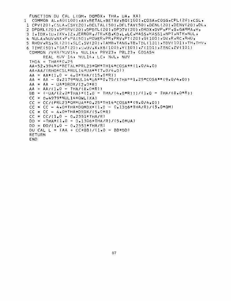
DU CAL L(QM, DQMDX, THA, UAt XA)COMMON AL,AQIIOO),AV,BETAL,BETAV,BQIIOO),COSA,COSG,CPL(20),CSL,
CPVI20),CSLA,CSVI20)_DELTALI50),DELTAV(50)_DENL(20),DENVI20),DL,
FUNCTION
1
1
2 DPDRLI20),DPDRV(20),DPDTL
3 I,[DX,IU,IXV,IZ,JERROR_JT4 NULA,NUV,NX,P_PA(50)_POWE
5 RHOV,RS,SL(20),SLC_SV(20)
6 TIME(50),TSAT(20),U,UV_X,
COMMON /VAR/NUV14_ NULl4,
REAL NUV 14, NUL14_ L
TH14 = THA**O°25
(20),DPDTVI20),DRDXgDVP,FP,G,GAMMA,H,
R,KB,KD,L,LC_MASS,MASS1,NPT_NTR,NUL,
R,PR,PRV_PT(20),Q(IOO),QW,R,RC,RHO,
,TAMB,TANG,TB,TDL(IO1),TDV(IO1),TH,THV,
XB(IOO),Y(IO1),Z(IO1),ZINC,ZV(101)
PRV23, PRL23, COSA5#
C, NUL, NUV
AA=52,394*G*BETAL*PRL23*QM*THI4_COSA**(1.0/4°O)
AA=AA/IRHO*CSL*NUL14*UA**(7°O/4°OI)
AA = AA*(1.O - 4.0*THA/(15AA = AA - 0.2179*NUL14*UA *
AA = AA - UA_DRDX/(2.0*R)
.O_R))_O°75/(THA_*1.25_COSA_(9°O/4,0))
AA = AA/(I°O - THA/(8°O*R))BB = (-UA/(2,O*THA)_(1.0 - THA/(4°O*R)))/(1,O - THA/(8°O_R))
CC = O°4979*NUL14_QWL(XA)
CC = CC/(PRL23*QM*UA_O,25_THI4_COSA**(9.O/4,0))
CC = CC - 4°O*THA_DQMDX*(I.0 - O.1306*THA/R)/IS,O*OM)
CC = CC - 4,O*THA*DRDX/(5°O*R)
CC = CC/(1,0 - O.2351*THA/R)
DD = -THA_(1,O - O°I306*THA/R)/(5,0*UA)
DD = DD/(I°O - O,2351*THA/R)
DUCAL L = (AA + CC*BB)/(I,O - BB*DD)
RETURN
END
87

27
30
FUNCTION OWL(XX)COMMON AL,AQ(IGO),AV,BETAL,BETAV,BQ(IOO),COSA,COSG,CPL(20),CSL,
I CPVI20),CSLA,CSVI2OI,DELTALISO),DELTAVISO),DENL(20),DENV(20),DL,2 DPDRL(20),DPDRV(20),DPDTL(20i,DPDTV(20),DRDX,DVP,FP,G,GAMMA,H,
3 I,IDX,IU,IXV,IZ,JERRORtJTR,KB,KD,L,LC,MASS,MASSI_NPT,NTR'NUL,
4 NULA,NUV,NX,P,PA(50),POWER,PR,PRV_PTC20),Q(IO0),QW,R,RC,RHO,
5 RHOV,RS,SL(20),SLC,SV(20),TAMB,TANG,TB,TDLI101),TDV(101)'TH,THV,
6 TIME(50),TSAT(20),U,UV_X,XB(190),Y(IOI),Z(IOI),ZINC,ZV(IOI)
DO 27 J=2,[XV
IF(XB(J).GT*XX) GO TO 30
CONTINUE
J=IXV
QWL=AQ(J)+BO(J)*XXRETURN
END
88
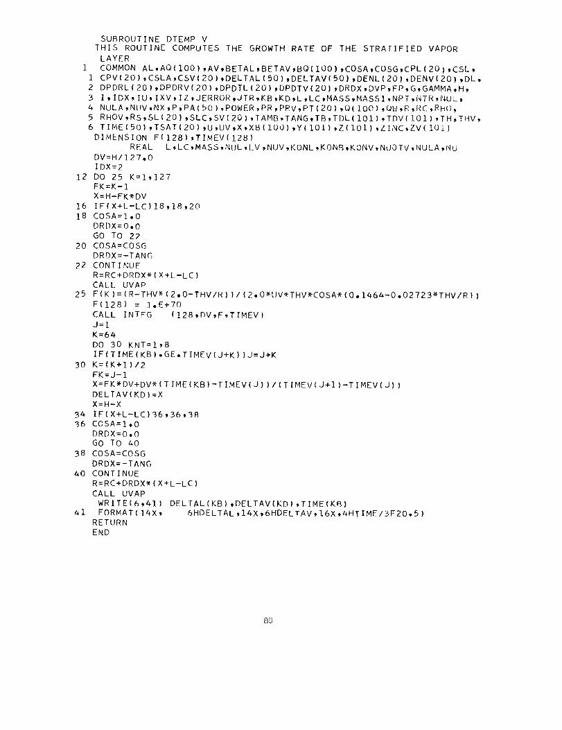
12
]6
18
20
22
25
3O
3436
38
40
41
SUBROUTINE DTEMP VTHIS ROUTINE COMPUTES THE GROWTH RATE OF THE STRATIFIED VAPOR
LAYER
COMMON AL,AQ(100) _AV�BETAL,BETAV,BQ(100) tCOSA_COSG,CPL(20) _CSL,
CPV(20),CSLA,CSVI20),DELTAL(50),DELTAV(50) _DENL(20),DENV(20) _DL_DPDRL(20),DPDRV(20),DPDTL(20)�DPDTV(20) _DRDX,DVP_FP,G_GAMMA,H_I,IDX,IU,IXV,IZ,JERROR,JTR,KB_KD_L,LC,MASS,MASSI.NPT,NTR_NUL,
NULA,NIIV_NX,P,PA(50),POWER_PR_PRV,PTI20),QIIOOI_QW,R,RC,RHO.
RHOV�RS,SL(20) _SLC,SV(20),TAMB,TANG,TB,TDLIIO1),TDV(IOI),TH_THV,
TIMEI50),TSAT(20),U,UV_X,XB[IOO),Y(IOI),Z(101),ZINC_ZV(IOI)
DIMENSION F(128) ,TIMEV(128)
REAL L ,LC 9MASS,NUL, LV _NUV _KONL ,KONB,KONV, NUO TV, NULA,Nu
DV=H/127,0IDX=2
DO 25 K=1,]27FK=K-1
X=H-FK*DV
IF(X+L-LC) 18,18_20COSA=I ,0
DRDX=O,OGO TO 22
COSA=COSG
DRDX=-TANGCONT I NUE
R=RC+DRDX*( X+L-LC )
CALL UVAP
F (K) = ( R-THV* ( 2, O-THV/R ) ) / (2, O*UV'_THV*COSA* (0o 1464-0 °02723*THV/R ) |F(128) = 1°E+70
CALL INTEG (128_DV,F,TIMEV)
J=l
K=64
DO 30 KNT=I,8
IF(T IME(KB) .GE. TIMEV(J+K ) ) J=J+K
K= ( K+I )/2
FK=J-1
X=FK*DV+DV-X-ITIME(KB)-TIMEV(J))/ITIMEV(J+I)-TIMEV(J) )
DELTAV(KD)=XX=H-X
IF(X+L-LC)36,36,38COSA=I ,0
DRDX=O,OGO TO 40
COSA=COSG
DRDX=-TANG
CONTINUE
R=RC+DRDX* (X+L-LC)
CALL UVAP
WRITE(6_41) DELTAL (KB) 4,DELTAV(KD) ,TIME (KB)FORMAT ( 14X , 6HDELTAL 914X _,6HDELTAV, 16X _,4HT I ME/3F20 ° 5 )
RETURN
END
89
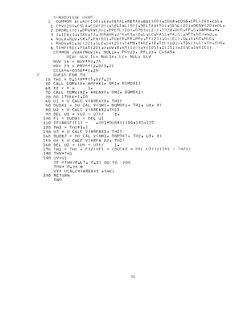
C
SIJBROUTINE UVAP
i COMMON AL,AO1100) ,AV,BETAL _BETAV,BQ(i00) ,COSA,COSG,CPL 120 _ ,CSL,
i CPV(201 ,CSLA,CSVI20),DFLTAL(5Ol _DFLTAVI50),DENL(20) ,DENVI20) ,DL_
2 DPDRL(20),DPDRV(2()),DPDTL(20) :DPDTV(2(") ,_RDX,DVP,FP,G,GAMMA,H_
3 ] , IDX _ IU, IXV, I Z, JERROR,JTR, KB,T<D,L ,LC,I_iASS,NASSL ,I'IPT,NT_<, NUL _
4 NULA,NUV,NX,P,PAIBO},POWER,PR,PPV,PT(20) ,(](ZOC),QW,R,RC,RHO_
5 RHOV,RS,SL(20),SLC,SV(2G),lAMB,TANC,TB,TDLI10].7,TDV(IO]-_'TH,THV,
6 TIME (50 I ,TSAT(20) ,U,UV,X,XB( IOU } ,Y (101) ,Z( I01 ) ,ZINE,ZV (IC1)
COMMON /VAR/NUV14, NULl1+, PRV23_ PRL23, CGSA54
REAL NUV 11+, NULl&, LC, NUL, NUV
NUV IZ+ = NUV**U,25
PRV 23 = PRVe"_(2,0/3,O)
COSA 51+=(OSA** ].• 25
GUESS FOR TH
10 TH1 = O°1_X**(5°O/7,0)
30 CALL DQMV(X, AREAX1, QMI, DOMDX1)
60 X2 = X + 1°
70 CALL DQMV(X2, AREAX2, OM2_ DQMDX2)
20 DO 170KK=1,20
1+O U1 = U CALC V(AREAXI, TH1)
50 DUDX1 = DUCAL V(OMI_ DQMDXl, TH], U1, X)
80 U2 = U CALC V(AREAX2,TH1}
gO DEL U1 = (U2 - U1)/ 1,1nO F1 = DUDX1 - DEL U1
110 IF(ABSF(F1) - °O01_-DUDX1)180,]80,120
120 TH2 = TH1*l°1130 U3 = U CALC VIAREAX1, TH2}
140 DUDX2 = DUCAL VIQ/41, DQMDX1, TH2, U3, X)
1_,0 U4 = U CALC VIAREA X2, TH2)
160 DEL U2 = (U4 - U3)/ 1,1"70 TH1 = TH] - F1/{IF1 - (DU[',X2 - DEL LI2))/(TH] - TH21)
180 THV=TH1
1QO UV=U]
IF (THV/R°LT° 0,2) GO TO 200THV= O,2_, R
UV= UEALCVIAREAX1 ,THV)200 RETURN
END
9O
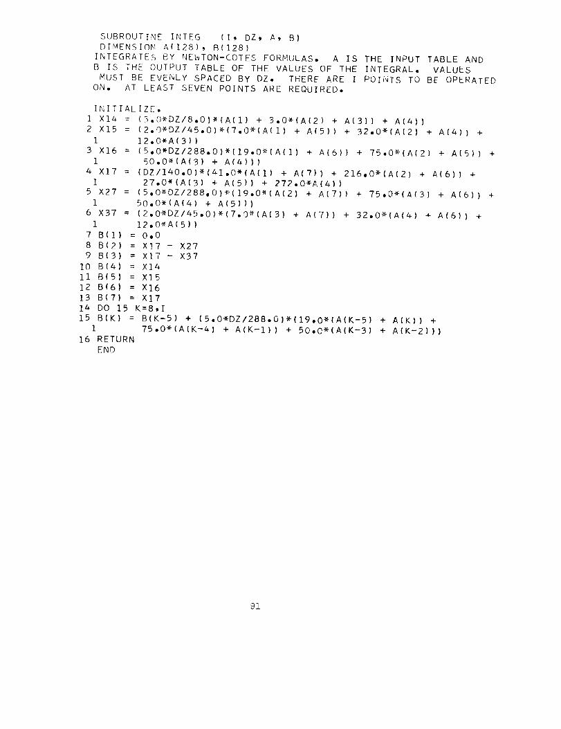
SUBROUTINE INTEG (I, DZ, A, B]
DIMENSION AI128), BI128)INTEGRATES BY NEWTON-COTES FORMULAS° A IS THE INPUT TABLE ANDB IS THE OUTPUT TABLE OF THE VALUES OF THE INTEGRAL, VALUES
MUST BE EVENLY SPACED BY DZ, THERE ARE I POINTS TO BE OPERATEDON, AT LEAST SEVEN POINTS ARE REQUIRED,
INITIALIZE,1 X14 = (3,0*DZ/8,0)*(A(1) + 3,0"(A(2) + A(3)) + A(4))
2 X15 = (2,0*DZ/45,0)*(7,0*(A(1) + A(5)) + 32,0"(A(2) + A(4)) +I ]2°0"A(3))
3 X16 = (5°O*DZ/288,0)*(19,O*(A(1) + A(6)) + 75,0_(A(2) + A(5)) +1 50,0"{A(3) + A(4)))
4 X17 = (DZ/140,O)*(41,0*(A(1) + A(7)) + 216.0"[A(2) + A(6))1 27,0"(A(3) + A(5)) + 272°O*A(4))
5 X27 = (5,0*DZ/288,0)_(19,0*(A(2) + A[7]) + 75,0"(A(3) + A(6)) +
1 50,0"(A(4) + A(5]])6 X37 = (2,0*DZ/45,0)*(7,0_(A(3) + A(7)) + 32,0"(A(4) + A(6)) +
1 12.0"A(5))
7 B(1) = 0.0
8 B(2) = X]7 - X279 B(3) = X17 - X37
10 B(4) = X1411B(5) = X1512 B(6) = X16
13 BIT) = X171_ DO 15 K=8,I15 BIK) = BIK-5) + (5.0*DZ/288.0)*I19,0*IA(K-5) + AIKI) +
1 75.0*(A(K-4] + A(K-1)) + 50.O*(A(K-B) + A(K-2])]
16 RETURNEND
91

SUBROUTINE DQMV (A8_A.QMgDQMI
1 COMMON AL,AQ(IOO),AV,BETAL,BETAV,BQ(1OO),COSA,COSGPCPLC20),CSL,
1 CPV(20},CSLA,CSVC20),DELTAL(50),DELTAV(5OI,D+ENLC20),DENVC20),DL,
2 DPDRLC20),DPDRV(20)_DPDTL(2Oi,DPDTVC20),DRDX,DVP,FP,G,GAMMA_H,
3 I,IDX,IU,IXV,IZ_JERROR,JTR.KB,KD,L,LC,MASS,MASS1,NPT,NTR,NUL,
4 NULA,NUV,NX,P,PA(5Oi,POWER,PR,PRV,PT(20).Q(IO0),QW,R,RC,RHO,
5 RHOV,RS,SL(20},SLC,SV(20),TAMB,TANG,TB,TDL(101),TDVCIO1),TH,THV,
6 TIME(50},TSATI20},U.UV,X,XB(1OO),Y(IO1),Z(101).ZINC,ZV(101)
REAL LC,L
XX=AS+L
AT=O,O
QT=0,O
DO 20 J=IXV,NX
IJ = J
IF(XB(J),GT.LC) GO TO 10
CO=1°0
TA=O°O
GO TO 15
10 CO=COSATA=-DRDX
15 CONTINUE
VALX=XB(J-1)
IF(VALX.LT,L) VALX=L
IF(XBIJ)oGE,XX} GO TO 30
XBI:XB(JI-VALX
XB2=XB(J)**2-VALX**2
XB3:XB(J)**3-VALX**3
AI=2°*RC*XBI-XB2*TA +2,*LC_XBI*TA
AX:A1*3°I4159265/COAT=AT+AX
AI:AI*AQ(J)
A2=XB2*RC-(2.*XB3*TA /3.)+XB2*TA *LC
A2=BQ(J)_A2QMI=3,141592651CO_(A1+A2}
QT=QT+QMI
20 CONTINUE
VALX=XB(IJ)
J=IJ
3O CONTINUE
XBI=XX-VALX
XB2=XX*_2-VALX*_2
XB3=XX_3-VALX_3
AI=2,_RC_XBI-XB2_TA +2._LC_XBI_TA
AX=A1_3°14159265/CO
AT=AT+AX
AI=AI_AQ(J)
A2=XB2_RC-(2._XB3_TA /3.)+XB2_TA _LC
A2=BQ(J)_A2
QMI=3,14159265/CO_(Al+A2)
QT=QT+QMI
AI=RC+LC_TADU=2,*3,14159265/CO_(AQ(J)_AI+XX_(BQ(J)_A1-AQ(J)_TA)-XX_XX_
1BQ(J)_TA)
DV=2°O_3,14159265/CO_(A1-XX_TA)
92

A=A]QM=OT/AT
DQM=(AT_QU-OT_OV)/(AT_AT)RETURN
END
93
FUNCTION U CALC V(ANCOMMONAL_AQ(IOO),A
i CPV(20)tCSLA_CSV(202 DPDRL(20)_DPDRV(20)3 I,IDX,IU,IXV,IZ,JER4 NULA,NUV,NX,P,PA(505 RHOV,RS,SL(20),SLC,6 TIME(50),TSAT(20),U
COMMON /VAR/NUV14, N
REAL NUV 14, NUU CALC V = (NUV14_AN
1 (I,0 - O,
RETURN
END
, THA)V,BETAL_BETAV_BQ(IOO),COSA,COSGtCPL(20),CSL,
),DELTAL(50),DELTAV(50)PDENL(20)tDENV(20)tDL,
,DPDTL(20),DPDTV(20),DRDX,DVP,FP,G,GAMMA,H,
ROR_JTR,KB,KD,L,LC_MASS,MASSI,NPT,NTR,NUL,
),POWER,PR,PRV,PT(20),Q(IOO)_QW,R,RC.RHO,
SVI20),TAMB.TANG,TB,TDL(IO1),TDV(IO1),TH,THV,
,UV,X,XB(IOO),Y(IO1),Z(IO1),ZINC,ZV(101)
UL14, PRV23, PRL23. COSA54
L14_ LC_ NUL, NUV
/(10.0946*PRV23*THA_*I.25*R_COSA54_
1306_THA/R)))**4
9,$

FUNCTION DU CAL V(QM. DQMDX, THA. UA. XA)1 COMMONAL,AQIIOOI.AV.BETAL.BETAV,BQ(IOOI.COSAtCOSGtCPLI20).CSLt
1 CPV(20).CSLA_CSV(20),DELTAL(50},DELTAV(50)tDENL(20).DENV(20)tDL.2 DPDRL(20),DPDRV(20}.DPDTL(20).DPDTV(20),DRDXtDVP.FP,G,GAMMA,H.3 I.IDX.IU_IXVtIZ,JERRORtJTR.KB.KD.L.LC.MASStMASS19NPT,NTR,NUL.4 NULA,NUV,NX,P,PA(50),POWER.PR_PRV.PT(20).Q(IOO)_QW.R.RC.RHO.5 RHOV.RS.SLI20).SLC,SVI20)gTANB.TANG_TB.TDL(IO1)tTDV(IO1).TH.THV,6 TIME(50),TSAT(20),U.UV_X_XB(IOO).Y(IO1).Z(IO1).ZINCgZV(101)
COMMON /VAR/NUV14. NULl4, PRV23. PRL23, COSA54
REAL NUV 14. NUL14_ LC. NUL, NUV
TH14 = THA**O,25
AA = 52o394*G_BETAV*PRV23_QM*TH1_COSA_*(I,O/_,O)
AA=AAIIRHOV_CSV(1)*NUV14*UA_(7,01#oO))
AA = AA*(1,0 - 4oO*THA/(15,0*R))
AA = AA - Oo2179*NUV14*UA*_O,75/(THA*_1o25*COSA**(9oO/4,0))
AA = AA - UA*DRDX/(2,0*R)
AA = AA/(1,0 - THA/(8,0_R))
BB = (-UAI(2,0*THA)*(1,0 - THAI(4.0*R)))I(1,0 - THAI(8.0*R))
CC = O,4979*NUV14*QWVIXA)
CC = CC/(PRV23_QM*UA**O,25_THl_COSA**(9,0/4,0))
CC = CC - 4,O*THA*DQMDX*(1,0 - O,1306*THA/R)/(5,0*QM)
CC = CC - 4,0*THA*DRDX/(5,0_R)
CC = CC/(1,0 - O,2351*THA/R)
DD = -THAW(I,0 - O,1306*THA/R)/(5,0*UA)
DD = DD/(I,0 - O,2351_THA/R)
DUCAL V = (AA + CC*BB)/(I.0 - BB*DD)
RETURN
END
95

FUNCTION oWVIXXX)1 COMMON AL_AQ(IOO),AV,BETAL,BETAV,BQ(IOO),COSA,COSG,CPL(20),CSL,
1 CPV(20),CSLA,CSV(20),DELTAL(50),DELTAVI50),DENL(20)_DENV(20},DL_2 DPDRL{20),DPDRVI20),DPDTL{20),DPDTVI20},DRDX,DVP,FP,G,GAMMA,H,
3 I,IDX,IU,IXV,IZ,JERRORgJTR,KB,KD_L,LC,MASS_MASS1,NPT,NTR,NUL,4 NULA,NUV,NX,P,PA(50),POWER,PR,PRV,PT(20),Q(IOO)_QW_R,RC,RHO,
5 RHOV,RS,SL(20),SLC,SV(20),TAMB,TANG_TB,TDL(IO1)_TDV(101),TH,THV,
6 TIMEISO),TSAT{20),U,UV_X,XB(IOO1,YIIO1}_Z(IO1),ZINC,ZVII01)
REAL LXX=XX×+L
DO 27 J=IXV,NXIF(XB(J),GToXX) GO TO 30
27 CONTINUE
J = NX30 QWV=AQ(J)+BQ(J)*XX
RETURNEND
96

SUBROUTINETHETAL1 COMMONAL,AQ(IOO),AV,BETAL,BETAV,BQ(IOO},COSA,COSG,CPL(20),CSL,
1 CPV(20}gCSLA_CSV(20),DELTAL(50),DELTAV(50),DENL(20),DENV(20)gDL,2 DPDRL(20),DPDRV(20),DPDTL(20),DPDTV(20),DRDX,DVP,FP,G,GAMMA,H,3 IgIDX,IU,IXV,IZ,JERROR_JTR,KB,KD,L,LC,MASS,MASSL,NPT,NTR,NUL,
4 NULA,NUV,NX,P,PA(5C),POWER,PR,PRV_PT(20),Q(IOO),QW,R,RC,RHO,
5 RHOV,RS,SL(20),SLC,SV(20),TAI4B,TANG,TB,TDL(IOI),TDV(IOI),TH,THV,
6 TIME(50),TSAT(20),U,UV,X,XB(IOO),Y(IOII,Z(IOI),ZINC,ZV(IOI)
DIMENSION RZ(IOI), TERM i(I01), TERM i I(lOl), TERM 2(101),
1 TERM 2 I(lO1)COMMON /VAR/NUVl#_ NULl4, PRV23, PRL23, COSA5&
REAL NUV 14, NUL14t LC, NUL, NUV, L, NULAXX=TH
XXX=U10 CSL = CSLA
20 NUL = NULA30 PR = NUL/AL40 NULl4 = NUL_O.25
50 PRL23 = PR_(2.0/3oO)60 PI = 3.1415926535
70 CON 1 = PRL23/IO.O228_CSL_RHO*NUL14}100 DZ = DELTAL(KB)/ZINC
110 IZ = ZINC111NPTS = IZ + 1120 IU = IZ + i
130 Z(1) = 0.0140 DO 150 J=2,NPTS
150 Z(J) = Z(J-1) + DZ
151 X = L - DELTAL(KB) - DZ
160 DO 420 J=I,NPTS
170 X = X + DZ
180 IF(X - LC)190,190,250
190 COSA = 1.0
200 C0SA54 = I.0
205 TANA=O.O
210 R = RC
220 RZ(J) : RC
230 DRDX = 0.0240 GO TO 290250 COSA = COSG255 TANA=TANG
260 C0SA54 = C0SA_1.25
270 DRDX = -TANG
280 R = RC - (X - LC)*TANG
290 RZ(J} : R
3O0 CALL U LIQ
310 CALL DQML(X, AREAZ, QMZt DQMDX)
320 THETA 1 = CON1_(QMZ_(TH_COSA)_Oo25)/U_O°75330 YINC = 10.0
340 NPTS Y = YINC + 1.0
350 D TH = TH/YINC
360 Y TH = 0.0
370 DO 400 JJ=I,NPTS Y380 THETA 2 = THETA 1"(1.0 - (Y TH/TH)**(I°O/7°O})
97

390 TERM 1(33) = ((R - Y TH)_THETA 2)/(1,0 + _ETAL#THETA 2)400 Y TH = Y TH + D TH410 CALL INTEG (NPTS Y_ D TH_ TERM 1_ TERM 1 I)
420 TERM 2(J) = TER_ 1 I(NPTS Y)
430 CALL INTEG (NPTS. DZ. TERM 2. TERM 2 I)
440 TERM 4 = QMZ*AREAZ*TIME(KD) + 2.0*PI*RHO*CSL*TERM 2 I(NPTS)
450 TERM 4 =(POWER+I.I*TERM 4/(DELTA L(KD)*PI*RHO*CSL)
470 DO 493 J=I,NPTS
480 IF(J-I)490.490,492
490 TDL(J) = 0.0
491 GO TO 493
492 TDLIJ} = (Z(J)/DELTALIKB))**(POWER )*TERM 4/RZIJ)**2
493 CONTINUE
TH:×X
U=XXX
5O0 RETURN
END
98
SUBROUTINE THETA V
I COMMON AL,AQ(100) ,AV,BETAL,BETAV,BQ(100) ,COSA,COSG,CPL (20) ,CSL,
1 CPV(20),CSLA,CSV(20),[)ELIALI50),DEI TAV(50),DENLI20),DENV(?Ol ,DL,
2 DPDRLI20),DPDRV(20) ,DPDTL(20),DPDTV(20),DR[);<,DVP,FP,G,GAMMA,H*
3 I,IDX,I[;,IXV,IZ,JERROR,JTR,KR,KD,L,LC,_ASS,_'IASS[,NPT,hTR,N_;L,
4 NULA,NUV,NX,P,PA(50),POWER,P_,PRV,PT(20} ,O(].DO) _()W,R_RC_IQIO,
5 RHOV,RS,SL(20),SLC,SV(201 ,TA!4B,TAP_G,TB,TDL[ 101),T!)V(1011 _iI4,THV,
6 TIMEISO),TSAT(20] ,U,UV,X,XB(IO[;),Y(1G1) ,Z(101) ,ZINC,ZV(ZOI)COMMON /VAR/t4UV14, NULl4, PRV23, PRL23, COSA54
REAL NUV 14, NULL4, LC, NUL, NUV, L, NULA
DIMENSION TERM I(I01), TERM 2(101)_ TERM 4(101), TERM 5(]01)
SOLUTION OF DIFFERENTIAL EQUATION IS BY THE RUNGE-KUTTA METHOD,
YY:THV
YYY=UV
10 IV = ZINC
20 NPTS = IV + 1
30 DV = DELTA V(KD)/ZINC40 ZVI1) = H - DELTA V(KD)
50 CSVV = CSV[1)
60 COSA5 = COSG*'1.2570 PI = 3,141592653580 THETA A = T AMB - TB
200 DO 210 J:2,NPTS
2]0 ZV(J) : ZV(J-]) + DV300 DO 480 J=I,NPTS
3]0 X = ZV(J)
320 IFIX + L - LC)33C,330,380330 COSA = 1.0
340 COSA54 = 1.0
350 R = RC360 DRDX = 0.0
370 GO TO 411
380 COSA = COSG390 COSA54 = COSA5
400 DRDX = -TANG410 R = RC - IX + L - LC)*TANG
411 TDV(J) = TB
420 CALL U VAP430 CALL DQMVIX, AREA, OM, DQMDX)
440 QWVA = QWV(X)
441 IF(J-NPTS)450,442t442442 TERM l(J) = QM*AREA/(H - X + DV/IO.O)
443 GO TO 460
450 TERM l(J) = QM*AREA/(H - X)
460 TERM 2(J) = 2.0*PI*QWVA/COSA*R470 TERM 4(J) = R*(1.O - THV/R)**2/IO.2927*UV*THV*COSA*
I (1.0 - O,18605_THV/R))
480 TERM 5(J) = PI*R*R*RHOV500 DO 970 J=I,NPTS
510 JJJ = NPTS - J + 1520 IF(J - NPTS)530,970,970
630 TERM 2 A = TERM 2(JJJ)
540 TERM 5 A = TERM 5(JJJ)550 TPS[ = TB
99

570 DO 950 JJ=l'JJJ
580 KK = JJJ - JJ + 1
590 IF(JJ - JJJ)600,9509950
600 TERM I A = TERM I(KK)
610 TERM 4 A = TERM 4(KK)
611 TPSIA = TPSI
620 KOUNT = 1
630 GO TO 900
640 SUM = XK650 TERM I A = (TERM I(KK) + TERM IIKK-I)I/2,0660 TERM 4 A = (TERM 4(KK) + TERM 4(KK-I)II2,0
670 TPSIA = TPSI + XK/2,0
680 KOUNT = 2690 GO TO 9OO700 SUM = SUM + XK*2,0
710 TPSIA = TPSI + XK/2,0720 KOUNT = 3730 GO TO 900740 SUM = SUM + XK*2,0750 TERM 1 A : TERM I(KK-1)
760 TERM 4 A = TERM 4IKK-1)770 TPSIA = TPSI + XK
780 KOUNT : 4
790 GO TO 900800 SUM : SUM + XK810 TPSI = TPSI + SUM/6,0
820 GO TO 950900 CSV(1) = PTCPIP, TPSIA)
910 TERM 3 : (THETA A + TB - TPSIA)/THETA A
920 XK = (TERM 1A + TERM 2 A'TERM 3)*DV*TERM 4 A/(TERM 5 A*CSV(1))*DV
9BO GO T0(640, 700t 740_ 800),KOUNT
95O CONTINUE
960 TDV(JJJ} = TPSI
9?0 CONTINUE
980 TDV(1) = 0,0
CSV(1) = CSVV
ZV(1) : 0,0
DO 990 J=2,NPTS
TDV(J) : TDV(J) - TB
990 ZV(J) = ZV(J-I) + DV
THV:YY
UV:YYY
RETURNEND
FUNCTION COSF(A)
lO0

COSF = COS(A)
RETURN
END
I01

FUNCTION ABSFIAIABSF = ABSIAIRETURNEND
102

FUNCTION PTCP(PRES,TEMP)PTCP=PTHEAT(PRES,TEMP,I)
RETURN
END
103

FUNCTION PTCV(PRES,TEMP)PTCV=PTHEAT(PRES,TEMP,2)
RETURN
END
104

FUNCTION PTGAMM(PRES,TEMP)
PTGAMM=PTHEAT(PRES,TEMPt3)
RETURN
END
lOS

2O
2
4
6
7
FUNCTION PTHEAT(PRESgTEMPtKTRANS)COMMON/SPHEAT/CP(823)ICV(823)
DIMENSION LOC(23)_JP(19)wMX(19),BP(19),DP(19),BT(23)gDT(19)_PS(12)
IPTS{12)tTL(10)
DATA PS/ioO22,2oP4otS._14. t25._43.t69._99._i28._lSI.p160./
DATA TS/24o845_27eOT,29e81_33.07p36.18t39°96_44.12t48°33951.97t
154,79P56e72957,46/
DATA LOC/1,50,71,113,133_141,1709165t228,264t348,372,426t492,528,
1584t626t638P734t654t682t694_718/DATA JPlTt3,69592,4t9t9o4t7_4_9,696p7_7p2t2pS/
DATA MX/5,1_4,3tO_2t2,492_5t2tTt4_4tS_590,Ot3/DATA BP/O°t20°_O°tlOOO.9100.t-lO00o_1469.690._1469°6,587°84_587.84
1,0.olO0°olO0.t40. o40°_O.oO-tlo/DATA BT/2600°t2600.t2600°_2600._800°_300°_120*_120._25*2_27o,72°_
181e_25._56._26°_41._25°_25._2600._5000,_5000._5000°,5000-/DATA DP/5°_40,_200._1000._4900._2000o_1175.68,293°92_1175*68_
1146_96_146.96_73.48,iOOe_100._20._20°_40*_40, tl,!DATA DT/4OO._400*t400°_800°_600°tlO0._30*_30*_12°6_9°_3°6"9°_ 5°_
15._4,,8°,4.,8._200o/DATA TLI24.846,27_175,29.310_31.299_33.176_34.962_36.672_38_317t
139.904_41_56/P=PRES*14.696IF(PoLT.I.O) P=l.O
T=TEMP*I,8
KTR=KTRANS
IFiT.LT.126-) GO TO 9
IF(T.LT.2600-) GO TO 5
IF(ToGE.6000.) T=5999.99999
IF(RoGE.IO0.) 6.0 TO
IF(P.GE.30.) GO TO
IF(P.GE.5.)GO TO 20
N=19
N1=19GO TO 33N=I
N1-20GO TO 33
N=2N1=21GO TO 33
IF(PeGE. IO00-) GO TO 4
N=3
NI=22
GO TO 33N-_
N1=23GO TO 33IF(T.LT°3OO,)GO TO 7
IF(T.LT.BOO.)GO TO 6
N=5GO TO 33
N=6GO TO 33
IF(PoLT.l_69.6) GO TO 8
106

N=7
GO TO 33
8 N=8GO TO 33
9 IF(P.LT,587.84) GO TO 12IF(PoLT,1469,6) GO TO 10N=9
GO TO 30lO IF(P,LT°lO28,72,AND,T,GE,72,0,AND,T,LT,90,O) GO TO 11
N=IO
GO TO 3011 N=11
GO TO 33
12 IFIT.LT,81.) GO TO 13
N=12
GO TO 33
13 IFIP.LT,160o) GO TO 15
TM=((.86867647E-7*P-,12613701E-3)_P+,lOB53383)*P+43,8056878
IF(T.GT,TM) GO TO 14
N=13
GO TO 3014 N=14
GO TO 33
15 DO 16 I=2,12
IF(P-PS(I})17,17,16
16 CONTINUE
I=12
17 TM=TS(I-I}+(TS(I)-TS(I-I))_(P-PS(I-1))/(PS(1)-PS(I-1))
IF(T,GE,TM) GO TO 18
N=15
IF(P,LTo40.) N=17
GO TO 3018 N=16
IF(P,LT,40°) N=18
GO TO 3330 F=P/587,84
I=F
IF(I°GT,8) I=8FI=I
F=F-FI
TQ=(I°O-F)*TL(I+I)+F*TL(I+2)
IF(ToLToTQ) T=TQ
33 IF(T.LE°5OOO.)N]=NFP=(P-BP(N})/DP(N)IP=FP
IF(IPoGToMX(N)) IP=MX(N)
FI=IPF=FP-FIFP=I,0-FFT=(T-BT(N1))/DT(N)IT=FTFI=IT
FF=FT-FIFT=I°O-FF
107

3536
37
I=IT_JP(N)+IP+LOC(NII
J=I+JPIN}
IFIKTR,EQ,2) GOT() 37CTCP=FP_FT_CP{I}+F_FT_CP(I+I}+FP_FF_CPCJ}+F_FF_CP{J+I}
IF{N,LT,13,OR,N,GE,17) GO TO 36
IF(N,LT,151 GO TO 35CTCP=CTCP/I187.506-P+ABS IT-TM)*28,13)
GO TO 36CTCP=CTCP/CABS CT-TM}/1,8+ABS (P-187,5061_,008008982}
IF(KTR,GE,2} GO TO 37
PTHEAT=CTCP_4,18674
RETURNPTHEAT=FP*FT_CVlI}+F_FT_CV(I+l}+FP_FF_CVCJ_+F*FF*CVIJ+l}*4,18674
IF(KTR,LT,3} RETURN
PTHEAT=CTCP/PTHEAT
RETURN
END
I08

BLOCK DATA
COMMON/SPHEAT/AA(111),AB(].1IItAC(111)gAD(111)_AE(II6},AF(II2),1AG(lll),AH(40),
2 AI(110),AJ(l11),AK(111),AL(111),AM(116),AN(112),AO(111)3,PP(4l)
DATAAA/3,80493,796,3,794,3,79a,3,793,3,793,3,793,4,025,3,951_3,937
1,3,931,3,927,3,924,3,922,4o655,4,259_4old4_4,15,4,13,4o117,_,I07,6
2°495,5°032,4°755_4o632,4°559,4°509_4°472_i0°98_6,839_6°054_5°706,5
3.498,5.356,5.252,20°06,10.48,8.6Z:6,7°8_4,7°35,7.02,6,776,35.35_16.
483_13.18_ii°55910,58,9.919,9°z'.29,3o793_3,792_3o792,3.924,3,917_3°9
513,4°l17,4°076,4.059,a°51,4°359,z'°298,5°3694°931,4°757,7.028,6°027
6,5o62,9°936,7°923,7°103,3°793,3°7QI,3°791,3o791,3°79!,3°79,5°916,3
7°9193.908,3°907_3°900,3°905,4.075,4.043,4.031,4,025,4°022,4.02,4°3
86,4,236,4°192,4°172,4°161,4.183,4,933_4.58194o457,4.401,4.369_4.34
96'6,03'5,21'4°92,4°791,4°71_,4°759,7°Q3,6°276,5°6Q2_5.4B3,5.279/
DATAAB/5°173,3°79t3°79_3°789,3_789,?°789,_,O2_4,014,4°OI1,4.OI_Z_oO
I08,4°346,4o29,4o265_4.25,ao24_5°17_,4.912_4.796,4°726,4o679_3°47_3
2°511,3.504_3.507,3°624,3°622_3°792,3.789_3°744_4°I08,4°297,4°3_6,3
3°658,3°842,3°951,4°015,3°537_3,637,3.708_3°7z_9,3°479,3°535_3°579,3
4°608,3°461,5°495,3°525_3°542_3°461,3°478,3o494,3°511_2°586,2°981,3
5.396,3.693,3.806,3.785,3°434,3.187_3.036,2.861,3°089_3.309_3.498,3
6.628_3,693,3o64_3°501,3,379_3.2_3°342_3oa74_3°584,3o673,3°737_3°8,
73°744,3°68!,3°519_3,633_3o738,3°826,3o903,3°957,4°03,4°041,4°015,3
8.744_3°838,3.921,3.994,4.06_4,111_4.223,4°248,4°243,3.877_3.951_4.
@O18,4°079,Z_-133,a.179,4,292,A°333,4._43,3.926_3.98_4°033,4.087/
DATAAC/4°I25,L.]52,4.263,4°317_4.346_I.334,1,264_I.217_I.2_I°884_I
1.742,1°667,1.587_2.387_2°151,2.025_i°947,2.871,2.506_2.337_2.232_3
2"311'2.792'2°584,2.461,3.668_3.035_2.789,2.652,3°846,3.23_2.968_2°
3821'3.84_3°37,3.113,2.963_?.767,3.475,3.25,3.104_1.543,1.515_1.491
4,1.468,1.447,1.A28,1.414_2°003_1.96,].922,1°89,1.862,1.835_1.812_2
5.51,2.426,2.357,2,301,2°253,2.21,2.173,3.151_2.967,2.836_2_734,2o6
652,2.585,2°529,4.07,3°651_3°383,3°198,3.063_2.956,2°871,5.417,4.48
76,3o997_3.69,5°477_3.318,3°196_5.793,5.081,4.509,4°i19,3°844,3°64_
83.484_4°855_4°893_4°637_4,339_4°084,_°879_3°714_4°14,4.37_4.391,4.
9286_4°134,3.98,3.84!,3.735,3.056,4°060,4.083_4.035_3.954,3.863/
DATAAD/3°505,3°692_3°819,3°881,3°891,3.a68_3.824,3_378_3.516_3°654
I_3°712,3°77_3°769_3°767_5°417_4.486_3°997_3°69,5.R2_Z:°795,A.229,3°
2862,5.887,5.022,4.43,4°033_5°659_5.!07_z_°573_4.163_5.23,5°054,_°6_
33,_,251,4°855,4.893_4.637,4.339_2°47,2°73_3,077_3,551,4°192,4.958_
45.659,5.946,5.793,2°482_2°678_2°916_3.205,3,549,3,916,4°304_4.637_
54.855,2°503,2°656,2°833_3.033_3°255_3.496_3,725,3°949,4.14_2.535_2
6°659,2°795,2°942_3°i,3°264_3°43_3.59,3°735_2°582,2°683,2°792,2._07
7,3°026,3,148,3°27_3o391,3°505,2.641_2.731,2.822_2,913_3.003_3°097,
83°191,3°284,3o378_25,22,30.03_35.61,40°25_44°37,48°45_24o47_30°!2_
936°7,42.16,47°08,51°94,22°95,29.45_36°95,43°16,48°7A,54°28_20.18/
DATAAE/27.65,36°2_43.19_49.AI_55.58_I6°I2,24.7a,34°5_42o3,49°IS_55
1.9,10.33,20.63,31.93_40,59_48°07,55.4_i.494,15.13_28o59_38°ii,46.1
25,53.98,-19°29_i0,62_24,91,35o,43.5_51.78_0o_8.28_17.76,30.56,39.5
33_48o33_0o,-55.,4.28_17,23_31.9,42,56,0°_0,_-9olI_3.79_17.,32.36,1
41o93_-5o256_i.59,0°_.ii,16o88,15.48_i!°,4°18_-13o56,0o,0°,23°81,18
5°76_13°42,-i°68,-17.82_0._31.05,25o95,27.7,!6.4!,3.2_-i0.31_78.05_
632.9_33.42_32.03,20,87_9,05,44o95_99.75_39°5V_39°66_34°95,24._6_I0
727.,I148,,1238°,1311.,1362,,1407.,1445,,962,3,1099.,1202.,1285,,13
844°,1394°,1438°,869o,i026.,i142.,1235.,1301.,1357.,1405.,727.5,906
109

9.9,1040._l145.P1219.,1282.t1335o,533.3,742.19895°5tlO16.,1099./DATAAF/l170.,1230.,333.8,512.89696.3,838.4t934.9,1015.91083. t91.2,
129012,434.2,603.4t720.39814.5t893.8_O.,O*t15314_302.5,433.2t558.1,2653o3_343.4972.4_-162,_20._151.5t276.4p378.8,929.7_692.1_477.8_2883.3t134. t90.2,-120ot1489.91269._lO82.t907.6t759.5t607.4,444.7p2037.
491817°t1634.,1469.,1331o,1195.,1053.,2584.92363.,2180ot2016.,1881.
591751.,1620.,3135. t2911.t2726.,2563.,2428.t2299.,2173.,1.566tlo557
691e78,1.77p2.059p2.037t2.377_2.333_2.?2612.724tl,O9113.21P2.46,5.2
786t2.45693.245_2,42893.431t2.434t3.02592.461t2o81392.463p2.712.465
8t2.638t2o47P2.612p35.34t16.83t13.18911o55tlO.58,9.919t9.429,54.51,
926.45,20o19,17.34t15.62t14.45,13.58t64.37t38.42929.61,25*31,22.66/
DATAAG/20.81tI9._3_56.31,49.66_39.93_34.49_30.94_28.41_26.46,9.931
1,7.923,Te103,15e62,10.89,9,417,22.66_15.12,12o?3,30.9_,20°32,16.85
2,7,93,6,276,5,692_50433_5,279_5,173_10o9_7,934_6,883,6,417,6,14,5,
395,15,15,10.31,8,585,7.82,7.364,7.052,17.4_,13.27,i0.71,9.57,8.89,
_8,_2_,5.17_,_.912,_,796,_.726,4,679,7,052,6,278,5.935,5.731,5.591,
59.796,8.258,7.575_7.167_6,891,0.,3.802,3,799_9,797,9.797,3,796,3.8
686,3.875_3,87,3.867,3.865,_,01,3.979,3.965,9,956,3,951,_.216,_.i_,
74,106,4.085,4,072_4.576_0_08,_.335,_0289,_,259,5,191,4.855,_.707,
84.618,4,558,6,202,5.582_5.308,5.144,5.032,7.785,6,713,6.238,5,954,
95.761,i0,15,8.396,7.619_7,155,6.899,13.53,10,8,9,588,8.865,8.372/
DATAAH/18.14,14.09,12,29,11.21_I0.47,24.18,18,44,15.86,14.B2,1B.26
1,31.64,23,93,20.41,18,28,16.82,40.2,30.53,25.96,23.16,21.23,48,9,3
27.93,32.38,28.89,26,_5,55.98,45.39,39,27,35.23,32.33,59.18,51.55,4
35,76,41.58,38,_2,57.08,54.85,50.68,47.04,_4,04/
DATAAI/2e819,2.811,2.809,2,809,2.808,2.808t2,808,3,032,2.963,2,95,
12.9_,2.9_,2.938,2.936,3,62_,3e255,3,186,3,155,3.136,3,12_,3,114,_
2,313,3,972,3,717,3.60_,3.537,3e_91_3._57,9,333,5,61,_,898_.582,4,
339_.265,¢.17,17,15,8.823,7,203,6._81_6,0¢9_5.75_,5.536,29,_7,1_.
%22,11,iI,9,705,8.862,8,28_,7.855,2.808,2.807_2,807,2,938,2,931,2.9
528,3.12_,3,086,3,07,3._92,3,553,3.296,4.268,3,878,3.719,5,762_.86
65,_.498,8.B,6.533,5,809_2.807,2,807,2.806,2.806_2.806,2,806,2.931,
72.925,2,923,2.922,2.921,2.92,3.085,3,055,3,0_4,3.039,3.036,3.03_,3
8,355,3,239,3,199,9.181,9,17,5,189,3,879,3,559,3,_6_3.395,3.365_3.
9945,4.867,4,129,3.867,3,751,3,682,3,72,6.5#I,5,077,_.557,_,327/
DATAAJ/_,I89,_.095,2,806,2.806,2,805,2,80_,2,803,3,034,3.029,5.026
1,3,02_,3,022,3.3_5,3.294,3.271,3,257,B.247,4.095,3,861,3,757,3.69_
2,3,652,2._85,2.509,2.519,2,52,2.699,2,637,2.807,2,803_2.884,2.996,
33,078,3,134,2.728,2,802_2.86,2.9,2.578,2.626,2,663,2.689,2.506,2.5
_98,2,562t2,578,2._82,2,50_,2.52,2.53,2._8,2.489,2.5,2,509,1.602,1.
5634,1.665,1.682,1.69_,I.706,1.758,1.8,1,838,1.876,1o895,1,911,I.92
69,1.9_7,1.961,2.005,2,0#6,2.08_,2,215,2.216,2,217,2.219,2,229,2.23
78,2.271,2.30_,2.338,2.533,2,543,2.552,2.56,2.571,2,58,2.617,2.65B,
82,684,2.759,2,776,2,791_2.806,2.82_2.833,2.882,2,92,2.951,2.892,2,
991,2.926,2.9_3,2,958,2,972,B,023,9.062,3.O93,2.9_,2.956,2.975/
DATAAK/2,989,3.003,B,OIS,3.06B,3,101,3.15_I.II3,1.083,1.06,1,05,1
I,B53,1.335,1.325,1.312,1._96,1._98,1,_9_,I._91,I.572,1.591,I,601,I
2.603,1,595,1.63,1.655,1,672,1,617,1.662,1,696,1,72_,i,651,I.699,1.
3738,1.771,i,693,1.7_I,I.782,1.819,1.757,1,807,1,85,1.888,1.173,1,I
_71,I.168_ie165,1,16,1.156,1.I_9,1,9_5,1-3_I,I.3_,i-358,1.33_,I,332
5,1.329,1,_56,1._55,1,_5_,I.W53,1._52,1,45,1._49,1,517,1,519,1.521,
61.523,1.525,1,526,1.527,1,551,i,552,1.556,1.561,I.56_,i.569,1,572,
71.583,I.571,I,571,i,575_I.581,I.587,1,591,I.61,I.591,I-584,1,584,1
8.589,1,59_,i.6,1,61,i.61tI,608,1,608,1-61,i,615,1,621,i,616,1.623,
ii0

91.627,1.632,1.63591.641ti.646,1.632,1.6491.64691.653,1°65_,I.665/DATAAL/I.671,1.665,1.67B,I.68,1o687,1.693,1.7,1o707,1.7!5,1.723,1.
1731,Io738,1o744,1.751,I.757,1.58391.571,I,571,I.575,1,597'i°578,1.2574,1.579,1.608,1.5@7,1,581,I.582,1.61,I.596,1.589,1.589,]-61,].BG34,1.598,1o598,1.61,I.61,I.608,1.608,1.485,1.511,].534,1.557,].577,41.604,1.621,i.621,i.61,I,495,1o516,1,534,i,552,1.569,I.583,1.996,15.606,1.61,1.516,1.53Z,l,54g,l.5&3,!.577,1,591,_.602,_.61,1°6_;,[,!_649,1.562,1.574,1.585,1.597,1.608,1,619,1.627_1.632,].595,1.606,].6715,1.625,1.634,1.642,1.652,1.66,1.665,1.656,1.664,1.671,1.679,1.6B86,1.693,1,701,I.708,1.715,1.131,I.132,1.]53,1.153,1.133,1.13],].249,1.239,1.238,1.237,1.236,[.235,!.342,].358,1.335,],332,1,33,1.328/
DATAAM/I.417,1.412,1.409,1.406,1,40z_,I°402,].46a,I,&£2,1.4_,!.459,ii.457,1.456,1.501,I.497,1.495,],495,1.495,].495,].565,1.555,1.529,21.52,1.52,1.522,1.754,1.78,1.564,].546,_o541,1.541,I.943,2.3,I.71,31.585,1.564,1.557,0.,2.4,1,808,1,653,],594,1,575,0.,0o,].62,1.683,41.624,1,591,1.583,2.3,3.1,0.,I.652,1.608,1.33,1.976,2.608,1.56,0.,50.,I.522,1.66,1.736,1.617,1.495,0.,i.527,1.589,1,679,1.663,1.609,16.56,1.522,1.563,1.608,1.6&8,1,627,1.601,I.52_i.551,!.579,1.613,].6722,1.609,],151,].152,1.152,].152,1.153,1.153_i.153,I.243,1.2_2,].2841,i.241,I.24,1.24,1o24,1.327,1.326,1.325,1.324,1.323,i.322,1.32!,91.393,1.392,1.391,1.39,!.589,!,388,1.387,1.4A,]oA39,1,438,I.a38/
DATAAN/I.437,1.436,1.456,1.478,1.474,1.473,1.@72,1o471,1.471,1.47,ii.508,1.503,1.506,1.50a,I.501,io5,1,498,0.,0.,I.547,1.546,1.548,1.2539,1.533,].646_],78,1.938,1.602,].615,1.628,1.641,].54_,I.607,1,639,1.805,1.978,2,346,2.652,].517,1.544,1.578,].623,1.687,].787,1.9642,1,504,1.518,1.534,1.551,i.57_I.592,1.618,1.498,1.508,1,517,1.5265,1.536,1.546,1.556_].499,].506,1.512,].519,1.526,1,532,1.539,1,1296,1.13,1.22,1.22,1,31,i7,1.7,1.475,1.671,i.4768.481,i.498,i.485,1.49993.57,21.93,!6.86,14,51
DATAAO/18.65,17.17,16.1,8.3,6.533,5.809,13.0823.88,6.611_5.077,4.557
.307,1.38,1.378,1.432,1.43,1,477,1.469,1o477
,!.619,1.477,!,544,1.478,1.517,1.478,1.504,1
,29.47,14.22,1].ii,9.705,8.862,8.284,7._55,4
,13.08,12.09,11.36,50.02,30.81,2A.I,20.75/
06,44,26,38.61,31,58,27.55,24.89,22o97,21.48
,9.068,7.803,18.65,12,54,10.56,24.89,16.66,1
,4.327,4.189,4.095,10,09,6.517,5.6,5.191,4.9
347,4o78,12.6,8.52,7.052,6.395,6.001,5.732
4.289,6.894,4,095,3.861,3,757,3.694,_.652,
546,8.056,6.756,6.173,5.816,5.449,0._2.817
62.899,2.888,2.883_2.881_2.879,3.018,2.989
73,142,3.111,3.092,5,079,3.55,3.394,3.525,
8.672,3.59,3.534,5.044,4,476,4.225,4.074,3
,16.8,10,95,8o824,7.865,7
5.732,5.06,4.761,4.58Z_,4.
,2.813,2.812,2.8!I,2,81!,
,2.976,2.968,2.963,3.214,
3.284,3.255,4.119,3,809,3
.972,6.a78_5.504,5.071,4.
9813,4.637,8.587,7.01W,6.314,5.895,5,609,iI.5_,9.]37,8.06],7.417/
DATAAP/6.976,15.49,11,99,10.42,9.471,8.822,20.48,15.66,13"46,12oI3
I,Ii.22,26._i,20.15,17.23,15.45,34.22,32.93,25-35,2!.67,19o4,17._I_
239.24,30.92_26.61_23.87_21.93,44.14_36.29,31.69,28.62,26.38,46.18,
340.53,36.27,93.17,30.8,4_.47,42.64,39.57,36.91,34.71/
END
iii

SUBROUTINE MASSCTHIS SUBROUTINE COMPUTES ULLAGE SPACE MASS AFTER
STRArIFICATION OCCURS
COMMON AL.AQ(IO0).AV.BETAL.BETAV,BQ(IOO),COSAtCOSG,CPL(20).CSL.
1 CPV(20),CSLA.CSV(20),DELTALCSO),DELTAV(5OI,DENL(20),DENVC20),DL.
2 DPDRL(20),DPDRV(20}.DPDTLC20),DPDTV(2C),DRDX.DVP.FP,G,GAMMA.H.
3 I,IDX.IU,IXV.IZ.JERRORtJTR,KB,KD,L,LC,MASStMASSI,NPT,NTR,NUL.
4 NULA.NUV,NX_P.PA(50),POWER,PR.PRV,PT(20),Q(IO0)_QW_R.RC,RHO.
5 RHOV.RS,SL(20),SLC.SV(20).TAMB.TANG.TB.TDL(IO1),TDV(IO1)_TH.THV,
6 TIME(50).TSAT(20).U.UV,X.XB(IO0),Y(IO1],ZIIO1),ZINC,ZV(101)
DIMENSION YI(IO1),PSAT(IO1).E (101),DML(1OIItDMV(IO!).VOL(!01}.
1 T(IO1),THETS(IO1), EI(IO1),EL(101)_Y2(IO1),Y3(IO1),E2(1C1),
2000
8OO
2 VOLI(IO1),TXX(101)REAL L.LC,MASS.LV_ MASS1
3 NPTS = IZ +1
KJ = 1
WRITE(6.2000) U,TH.UV.THVFORMATI1X,11HU_TH_UV_THV _4F20o6)
DML(1)=O.OPSATI1)=VP(TDLINPTS)+TB)PRESS=PSAT(1 )CALL MASSUIPRESS,CMT_TDLINPTSI+TB)
Y(1) = (3°14159*(RS_*2)*TDL(NPTSI_RHO*CSLA)YlI1)=3.14159*RS**2
DMV(1 )=CMT -MASS1IF(DMV(1}.LT°O,O) GO TO 29
WRITE (6,250)DO 20 JJ = 1,IZ
8 J=NPTS -JJFIND SATURATED PRESSURE FOR EACH MASS
PSAT(JJ+I)=VP(TDL(J)+TB)DMASS TABLE FOR LIQUID
17 R=RS+IDELTAL(KB}-Z(J))*TANG
18 IFIR.GT.RC) R=RC
19 YIJJ+I)= (3-14159_(R*'2)*Y1(JJ+1)=3°14159_R_*2
20 CONTINUEDZZ=ZINPTS)-Z(IZ)
21 CALL INTEG (IU _DZZ_Y_ECALL INTEG (IU_DZZ_YI_VOL]
IF(IU,EQ.NPTS) GO TO 23
IL=NPTS+I-IU
DO 800 JJ=I,IL
J=IU+JJ-1Y2(JJ)=Y(J)
Y3(JJ)=YI(J)
CONTINUE
DZZ=Z(2)
CALL INTEG (II..DZZ,Y2,E2)
CALL INTEG (IL.DZZ.Y3.VOL1)
DO 900 JJ=2,1L
J=IU+JJ-1EIJI=E(IU)+E2IJJ)
VOL(J)=VOL(IU)+VOLI(JJ)
TDL(J) _RHO_CSLA}
i12

900 CONTINUE23 DO 25 JJ = 1,IZ
J = NPTS -JJ
ZN=DELTAL(KB)-Z(J)ES=TDL(J)*RHO_CSLA*VOL(JJ+I)
24 EL(JJ+I) = E(JJ+I)- ES
25 CONTINUEWRITE(6_3000) E(NPTS)
3000 FORNAT(16HOTOTAL ENERGY
28 GO TO 145
29 WRITE (6,200)30 X=2,0*SORT (AL*TIME(KD))
32 Y1(1)=3,14159*RS**2*RHO*CSLA34 JJ=IZ/8*8 +136 DZ=(Z(NPTS)-Z(IZ))/16,0
38 KJ=KJ+I42 JKI:IZ
46 ZI=DZ
48 DO 94 III=2,JJ50 PHE=Z1/X
52 ERZ=ERF(PHE)5354
127
,E15.6)
IF((DELTAL(KB)-Z1).LT.Z(JKI)) JKI:JKI-1
TXX(III):TDL(JKI+I)-(TDL(JKI+I)-TDL(JKI))*(Z(JKI+I)-(DELTAL(KB)
1-Z1))/(Z(JKI+I)-Z(JKI))
56 THETS(III)=TXX(III)/(1.0-ERZ)
58 IF((THETS(III)+TB)-32.5) 70,70,59
59 IF(III-8) 65,60,60
60 NINT=III-1
62 GO TO 106
65 DZ=DZ/2°O66 GO TO 3870 PSAT(III)=VP(THETS(III)+TB)
78 R=RS+ZI*TANG80 IF(R°GT,RC) R=RC
82 Y(III)=3.14159*R**2*RHO*CSLA*TXX(III)
84 Y1(III)=3.14159*R**2*RHO*CSLA * (1.0-ERZ)
86 ZI=ZI+DZ
94 CONTINUE
104 NINT=III
106 CALL INTEG (NINT,DZ,Y1, E)
108 CALL INTEG (NINT,DZ,Y, El)
110 DO 114 III=2,NINT
112 EL(Ill)= El(Ill)- E(III)*THETS(III)
114 CONTINUE
116 PRESS=PSATININT)117 DML(NINT)=DMF(PRESS,THETS(NINT)+TB,EL(NINT))
118 CALL NASSU(PRESS,CMT,THETS(NINT)+T8)
120 DNV(NINT)=CMT-MASS1121 CONTINUE122 IF(DML(NINT)-DMV(NINT)) 132,132_124124 IF(2*NINT-JJ)126,126,128126 IF(KJ.GTolO) GO TO 173
DZ=DZ/2°O
GO TO 38
I13

128 DZ=DZ*2,0IF(KJ,GT,IO) GO TO 173
130 GO TO 38
132 CONTINUE133 111=1134 KA=NINT-2
135 KA=(KA+I)/2136 JJ=III+KA
IFIJJ.GT.NPTS} JJ:NPTS
137 PRESS=PSAT(JJ)DML(JJ)=DMF(PRESS,THETS(JJ)+TB,EL(JJ))
138 CALL MASSU(PRESS,CMT,THETS(JJ)+TB)
139 DMV(JJ)=CMT-MASS1140 IF(DML(JJ).GE.DMV(JJ)) III:III+KA
IF(KA°GT.]) GO TO 135TS=THETSIIII+I)+T_TSI=THETS(III)+TB
TS2=THETS(III+I)+TBTI3=TXX(III)+TBTI4=TXXIIII+1)+TB
143 GO TO 154145 III:1
KA=NPTS-2146 KA=(KA+I)/2
JJ=III+KAIF(JJ.GT.NPTS) JJ:NPTSPRESS=PSAT(JJ)
TDLL=TDL(NPTS-JJ+I)+TBDML(JJ}=DMF(PRESSgTDLL_EL(JJ))
CALL NASSUIPRESS_CMT,TDLL)DMV(JJ)=CMT-MASS1
147 IF(DMV(JJ).GE°DML(JJ)) III=II]+KA
IF(KA.GT.1) GO TO 146TS=TDL(NPTS-III)+TB
TSI=TDL(NPTS-III+I)+TBTS2=TDL(NPTS-III)+TBTI3=TS1
TI4=TS2154 JJ=Ill
PRESS=PSAT(JJ+I)
DML(JJ+I}=DMF(PRESS,TS,EL(JJ+I))
156 CALL MASSU(PRESS,CMT,TS)
158 DMV(JJ+I)=CMT-MASS1
160 PN=PSAT{JJ)_(DML(JJ+I)-DMV(JJ+I)}-PSAT(JJ+I)
I*(DMLIJJ|-DMV(JJ)}162 PD=DMV(JJ)-DMV(JJ+I)+DNL(JJ+I)-DML(JJ)
164 P=PN/PDTSURF=TSI+(TS2-TS1)*(P-PSAT(JJ))/(PSAT(JJ+I)-PSAT(JJ))
TINT=TI3+(TI4-TI3)*(P-PSAT(JJ))/(PSAT(JJ+I)-PSAT(JJ))166 DME=DMV(JJ+I)+(DMV(JJ}-DMV(JJ+I})*(P-PSAT(JJ+I))
1 /(PSAT(JJ)-PSAT(JJ+I)|168 KB=KB+t170 KD=KD+I171 WRITE(6,264) DME,DMV(JJ)_DMV(JJ+I)_PSAT(JJ)_PSAT(JJ+I)t
114

1 D'-:L ( J J) ,DML (JJ+l)
172 WRITE(6_,260) P,TSURF,TINTGO TO 174
173 WRITE(6,220)JERROR = 2
P=12,759174 RETURN200 FORMAT(///_ CONDENSING CASE CALLED SUB MASS Ct/ )220 FORMAT(120H ***-_*****_-_****<***ERROR IN MASSC PRESSURE IN ULLAGE A
lPPROACH_NG OR IS IN EXCESS OF CRITICAL PRESSURE *****_**_*_*****
2 // 120H ***************************************************** CRITICAL
3 POINT VALUE IS RETURNED **-*-****-***************-********************
250 FORMAT(///GX, 40HEVAPORATING CASE CALLED SUB. MASS C / )
260 FORMAT(IHO,IOX,GHNEW P=,F7°4,12H ATMOSPHERES,IOX,
113HSURFACE TEMP.,F7.3,10X,15HINTERSECT TEMP.,
2F7,3,2X,GHDEG K.)264 FORMAT(15X,3HDME,IOX_7HDMV(J,J) _7X,9HDMVIJJ+I) t7X,8HPSAT(J ,J)
16X_ IOHPSAT (J J+l) ,9X,7HDML(JJ) _6X,9HDML(JJ+I)/SX,7FIS,4)
END
i15

FUNCTION VP(TEMP)
T=TEMP
IF(T,LT,13,803) GO TO 4
IF(T,LT,20,268) GO TO 3
IF(T,GT,32,976) GO TO 6
8 V=2.00062-50,O9708/(T+IeOO44)+O,OI748495*T
P=IO,O**V
IF(T-29.0)1.1.2
I VP=PRETURN
2 A=T-29.0TTT=A*A*A
TF=TTT*A*ATS=TTT*A*TTTVP=P+O,OO1317*TTT-O.OOOO59Z6*TF+O,OOOOO3913*T$
RETURN3 VP=lOoO**(1,772454-44,36888/T+O,O2055468*T)
RETURN4 WRITE(6t5)
5 FORMAT{120H ***********************************e****** TEMPERATURE
i IS BELOW TRIPLE POINT ******************************************
2 / / 120H ********************************************* TRIPLE P
3OINT VALUE RETURNED **********************************************
T=13.803
GO TO 3
6 WRITE (6.7)7 FORMAT(120H ***************************************** TEMPERATURE
lI5 ABOVE CRITICAL POINT *****************************************
2 // 120H ********************************************* CRITICAL
3 POINT VALUE IS RETURNED ****************************************)
T=32,976
GO TO 8
END
]-]-6

L)UBROUTINE MASSU(PRESS_.CMT,TS)
THIS ROUTINE COMPUTES AN ULLAGE MASS GIVEN A PRESSURE = PRESS
AND RETt;F-NS A MASS = CMT
] CO MIv,ON I_L, AO ( 100 ) _,AV,BETAL,,BETAV,BQ( 10C, ) _,COSA,,COSG 9CPL ( 20 ) , CSL,
1 _PV(20) ,CSLA _CSV(20) ,DELTAL (50) ,DELTAV(50) ,DENL(20) _DENV[20 ) ,DL,2 DPF)RL.{ZO)_L)P[_'RV(20),DPDTL(20) :DPDTV(20) _DRDX_D\IP_FP_G_GAMMA_H_B I,IP, X_IU;I
4 _,!tJLA ,NU'.I ,51
5 RHOV,RS,SL
5 FI_4E(5C}, F
D I :%NS I ON
! 'f1(101)REAL L _LC
5 NPTS = IZ+I
31 RO=IFIND DIPRESS_0.50,TS)I-_0o00201572
32 IF(L.LT.LCI GO TO 57
CASE I STRATIFIED LAYER ENTIRELY IN NOSE CONE
C,ML ( 1 )=RO_3.14159. ( (RSVP-2 )*(H-DELTAV (KDI 1-RS* C CH-DELTAV(KD) )
_x-2):,_TANG+(I IH-DELI-AVIKD) I*_3)/3.0)*(TANGX*2) )
XV ._I Z ,JE_IXOR,JTR ,KS,K[)_.L _.LC ,.I:',ASS,MASSI ,NPT ,NTR,NUL ,,,.
X:P.-PA(50) :PCWER,PR,PRVgPT(20) ,-Q(IO0} ,QW,R_RC,RHO,
(2g') _SL(:_SV<2('/,TAMB,TA.NG,TB_TDLI101),TDV(101),TH,TFIV,•5AI (2I',) } ,[!_UV IX _X;: ( lOUt _Y ( iOl ) ,Z ( 101 I ,ZINC ,ZV ( i011
r.:Mb(lCll ,Ct!1181},CMLI!CI),ZVi[101},CMU2CIOI},CMUl(IOI),
TRANSITION
BELOW TANK TRANSITION
ZV IN CMU---IN MASSC)
_4
1
37 TANA = TANG
33 DZ = DELTAV(KDIIZINC39 ZV(I) = 0.0
A! r,o 42 LK = 2,NPTS
_2 ZV(LK) = ZVILK-1) + DZ
_5 DO_9 K = 1,NPTS
46 R = RC-(L+H-DELTAV(KDI+ZVIKi-LCi_TANA
r = TDV(K)+TS
#7 RHOG=iFIND DIPRESS,O.50_T}}_O°O0201572
48 Y(KI = 3.14159_RHOG_IR_2)
_9 CONTINUE
51 CALL INTEG ( NPTS_ DZ_ Y_ CMU)
C_4T=CML(1)+CMIJ(NPTS)
56 RETURNCASE 2 STRATIFIED LAYER CROSSES TANK
PROPORTION STRATIFIED LAYER ABOVE AND
57 IF (L+H-DELTAVIKDIoGT.LC} GO TO 10559 DU = L+H-LC
50 DL!. = DELTAV(KD)-DU
61 F_ACTL = DLL/DELTAV(KD)52 NPTSL = FRACTL _ZINC+I.0
63 IFINPTSL.GE.7) GO TO 67
64 NPTSL = 7
65 NoTSU = NPTS-6
66 GO TO 71
67 NPTSU = NPTS-NPTSL+Z
68 IF(NPTSU°GEoT) GO TO 76
69 NPTSU = 770 NPTSL = NPTS-67] IF(NPTS.GEol5) GO TO 7672 PRINT 73
73 FORMAT(48H1 NOT ENOUGH INCREMENTS FOR
74 JERROR = 2
75 RETURN
76 DZU = DU/(NPTSU-1)
117

77 DZL = DLLI(NPTSL-1)TABLE OF Y(K) FOR CYLINDER SECTION
78 ZV(1) = O°O
79 TANA = 0°0SO DO 84 KK = 1,NPTSL
81 R = RC-(L+H-DELTAV(KD)+ZV(KK)-LC)*TANAT = TDV(KK) + TS
82 R:HOG=(FIND DiPRESS,O°50oT))*O.O0201572
_3 Y(KK) = 3.14159*RHOG*(R**2)84 ZV(KK+I) = ZV(KK)+DZL
85 CALL It4TEG ( NPTSL, DZL, Y, CMLJ1)HASS IN CYLINDER SECTION BELOW STRATIFIED LAYER
86 CL1 = 3°14159*RO*IRC**2)*( H-DELTAV(KD))MASS IN PORTION OF ULLAGE BELOW TANK TRANSITION
88 CMLINPTSL)=CLI+CMUI(NPTSL)_ASS IN PORTION OF ULLAGE ABOVE TANK TRANSITION
91 TANA =TANG92 ZVI(1) = ZV(NPTSL)93 DO 97 JI = 1,NPTSU9zr R = RC-(L+H-DELTAV(KDI+ZVI(JI)-LC)*TANA
N=NPTSL-I+JIT=TDVIN)+TS
95 RHOG=(FIND D(PRESS,O.509T))*O,O020157296 YI(JI) = 3°14159*RHOG*(R**2)97 ZVIIJI+I) = ZVI(JI)+DZU98 CALL INTEG ( NPTSU,DZU, Y1, CMU2)
TOTAL MASS IN ULLAGE SPACECMT=CML(NPTSL)+CMU2(NPTSU)
RETURNCASE 3 UNSTRATIFIED PORTION OF ULLAGE CROSSES
104
TANK TRANSITION
MASS IN CYLINDER PORTION105 CL1 = 3,14159*RO*(RC**2)*(LC-L)
MASS IN NOSE BELOW STRATIFIED LAYER
H2=(L+H-DELTAV(KD)-LC)
106 RI=RS-H2*TANG107 CL2=3.14159*H2/3.*(RS**2+Rl*_2+RS*R1)*RO
MASS BELOW STRATIFIED LAYER
108 CML(1) = CL1 + CL2
109 DZ = DELTAV(KD)/ZINC
110 TANA = TANG112 ZV(1) = 0.0!13 DO 114 K = 2,NPTS
114 ZVIK ) = ZV(K -1) + DZ115 CONTINUE116 DO120 JC = 1,NPTS117 R = RC-(L+H-DELTAV(KD)+ZV(JC)-LC)*TANA
T = TDV(JC)+TS118 RHOG=(FIND D(PRESS,O°50tT))*O,O0201572
119 Y(JC) = 3.14159*RHOGm(R**2)120 CONTINUE121 CALL INTEG (NPTS, DZ9 Y_ CMU)
TOTAL MASS IN ULLAGE126 CMT=CML(1)+CMU(NPTS)

127 RETURNEND
i19
FUNCT IOND It,_ENS ION
D I MENS I ON
ERFIX)
B( i0, iO ) ,V(5) ,VINCR(5) ,Y(256) ,NVALUS(5 )
AA(5C),A-B(451,ACI45),AD[45),AEI45),AF(26)
EQUIVALENCE(AA,Y),(#.B,Y(51) ) ,(AC,,Y(96) ),(AD,Y(141)),
['/OUTV,6LENCE(AF,Y(231))
DATA AA/0•0,•02256457469,•04511110615,•06762159439
I • i 12462'J 1602, • 13475635182 , • 156947C3306,. 17901181320
2 •2227025892] ,•2442c591160,.26570005895,.28689972322
• " ' 36936452934,.389329701133 .3286267594_ ,•349125c#_480,.
4 .42839235505, •4z_746761843 ,. 46622511528,. 48465539000
5 .52C,' 9987781,•5378086304_,.55493925046,.57161576382
5 •6038550°C35 , •619411461g0, • 63458582912 , • 64937668796
v •677g0119__84,. 691433i2314, • 70467807785,. 71753675281
;} •7421009647! , • 75381075087, • 76514271145, • Z7610026832
9 .7969C'321242 ,. 80676772155 ,. 81627101898, • 82542364964
(AE,Y(186))
,.09007812584,
,.20093583902,
,.30788006803,
,.40900945342,
,.50274967069,
,.58792290038,
,.66378220274,
,.73001043130,
,.78668731917,
,•83423150434/
DATA AB/
1 .84270079295,.84883447667,.85478421145,.86055291752,.86614358664,
2 .87155927596,.87680310194,.88187823430,.88678789017,.89153532819,
3 •8961238429a,.90055675926,.90483742692,.90896921523,.91295550797,
4 •91679969838,.92050518430,•92407536352,.92751362930
5 .93400794A94,•93707072048,•94001502616,.94284417109
6 .94_17007278,.9506732958!,•95307428466,.95537617864
7 •9596(_502564,.96!718C3684,.96365406541,.96550601777
8 .96896905700,•97058568986,.97212933600,.97360262746
9 .97634838334,•97762581857,.97884283967,.98000178222
i
2
3
4
6
7
8
9
.98215447153,. 98315258690,. 98410136103
•98667167122 , . 98744281785 ,•98817419593
•990146822_0,. 99073594755 , • 99129343540
•992790z_Z-) 24, . ')932'3540256 _ . 9")365565017
.99477898959, • _9511141320, • 99542@57260
,.98500282736
,•98886754427
,.99182074761
,.99405220070
,.99571945145
.9962580_60AI,.£_9630362661,•99673440867,.99695123054
•9973459706q,.99752529267,•99769346440,.99785110820
.99813715370,.99826665559,•99838783206,.99850116734
•99870612960,.99879860642,•99888494363,.99896551257
.99911073297,.99917o03!60,.99923685799,.99929349295
.9993952340i,.99944032612,•99948320022,.99952256573
.9995930q798,.99962452471,.99965371398,.99968076986
.99972905108,.99975053947,.99977042149,•99978880894,.999_0580653,
•99982151225,.99983601774,•99984940871,•99986176523,.99987316207,
.99989366905,.99989335129,•99990226950,.99991048029,.99991803636,
.99992498681,•99993137v2 _;., ,..°999 _725025,•99994264521.
•99995214516,. 9909503151_2 , • 99996014013, • 99996364527
.999969 79696, • 9999724884'+, . 99997495086, • 99997790950
] .99998285914,.9999849i842,.99998674048,.99998835134
2 .99999103043,.99999213826,.99990311455,.99999397424
3 .99999539565,.99999597982,.99999649258,.99999694229
4 .99(_99768150,.99999798344,•9999982474!,.99999847801
5 •99999885482,.99990900780,.99999914100,•99999925690
6 •99999944518_.99999952115,.99999958704,.99999964414
7 .99999973655,.99999977333,•99999980528,•99999983285
8 .99999987712,•99999989476,.99999990995,•99999992300
,.93082336599,
,.94556143656,
,.95758207481,
,.96727674813,
,.97500813820,
,.98110492131/
DATA AC/
,.98585895940,
,.98952454462,
,.99231929313,
,.99442627546,
,.99599699195,
,.99715484503,
,.99799881667,
,.99860712112,
,.99904066481/
DATA AD/
,.99934620158,
,.99955911981,
,.99970583698,
,.99994759883,
,.99996685644,
,.99998053361/
DATA AE/
,.99998977436,
,.99999473065,
,.99999733640,
,.99999867928,
,.99999935766,
,.99999969358,
,.99999985663,
,.99999993920,
120

7
15
11
21
17
25
57
27
31
63
6O
62
9 .9799_#99520. _
.9999I) gT65dU
o_9999_99597
._999999V3_I
._'999_:99#9d0
.9999999979U
DATA NVALUS/5
DATA ViNCR/O.
DATA V/I.G,2o
LV=5
KK:7_CT_JT=.IE-IO
PI=3.1415926536
IF(X)5,15,7
X=-X
SIGN:-I.OGO TO II
SIGN=I.O
GO TO II
ERF=O.O
GO TO IOl
IFIX-5.75 )17,17,21
ERF:SIGNX=X_SIGN
GO TO 101DO 25 L=I,LVIF(X-V(L))27,57,25
CONTINUE
YY:Y(256)
DELTAX=X-5.7
Xi:5°7
GO TO 59
N=NVALUS(LI
ERF=Y(NI*SIGN
X=X*SIGN
GO TO i01IF(L-I)31,31,33
INTPT=X/VINCR(I)
IF(INTPT)63,63,64
DELTAX=X
YY=O.O
FACTOR=I.1283791671
DENOM=I.O
AK=DELTAX
SUM=AK*FACTOR
DO 62 J=2,KK
QJ=J
,.99999996230,.99999997039,o99999997678,o99999998i83/
DATA AF/
,.9999_98893,.99999999138,.99999999330,°9999999948U,
,._)9_99999689,.99999999760_.99999999815,.99999999858,
,.9999999_916,._9999999936,°99999999951_o99999999969_
,.79099_W9988,.99999999992_.99999999995,.99999999997_
,°999_9999997,.99999999999_i°091°0,i.0/
1,183,224,24zi,256/
02,0o015_0°0210°03,0.05/
98,3o8,6.4_5°N/
AK=DELTAX*DELTAX*AK*(2,0*QJ-3,O)/(2,O_QJ-I,O)
DENOM=(QJ-I°0)*DENOM
TERMK=FACTOR*AK*((-I.OI**(J-I))/DENOM
ISUM=SUM+TERMKIF( ABS(TERMK)-TEST)41,41,62
CONTINUE
121

$4GO TO 41QINTPT:INTPT
XI=QINTPT_VINCR(1)
DELTAX:X-X1
N=I
GO TO 35
33 INTPT=(X-V(L-I))/VINCR(L)
QINTPT=INTPT
XI=(OINTPT_VINCR(L))+V(L-1)
I)ELTAX=X-XI
N=_!VALUSIL-1)
35 NJ=INTPT+NYY=Y(NJ)
59 FACTOR=1.1283791671_EXPI-Xl_X1)
DENOM=I.0_1 U=DELTAX/X1
Q=DELTAX_X1BII,1)=DELTAX
SUN=BII,1)_FACTORDO 37 K=2,KKQK=KB(K,1)=2.O_{Q*(QK-I,0)*BIK-I,t)/QKAK=B(K,1)DO 39 I=2,;<OI=IB(Kgl)=(u_(QK+QI-2,0)_(QK-QI+I,)_B(K_I-I))/(2,*IQK+QI-I°)_(QI-I°))
39 AK=AK+BIK_I)DE_IOM=(QK-I,0)_DENOM
TERMK=FACTOR_AKX((-I,0)_IK-1))/DENONSU#_=SUH+TERN, KIF( ABS(TERMK)-TEST)41,41,37
37 CO_!TINUE41ERF=IYY+SUM)_SIGN
X=X_SIGN
101 RETURNEND
122

FUNCTIONDMFIPRESS,T,E}I COMM..3NAL,A'3(IOOI,AV,BETAL,BETAV,BQ(IO0| ,COSA,COSG,CPLi20),CSL,
1 CPVI20)_CSLA.CSV(20),DELTAL(SS),DELTAVISO)'DENL(20)'DENV(2OI'DL"
2 DPDRL(20),DPDRV(2C),DPDTL(20},DPDTVIZC)'DRDX'DVP'FP'G'GAMMA'H'
3 I,[DX,IC,IXV,IZ,JERROR_JTR,KB,K-D,L*LC" _ASS_!'4ASSI*NPT'r_TR'NUL"
4 _IIJLA,NUV,NX,P.PA (50) ,POWER,DR,PRV*PT(20) ,Q( IO0| ,QW,R,RC,RHO,
5 _HOV,R.S,SL(2C;,SLC,SV,'20).',Te.,'4B_TANG,T_*TDL[IOI)'TDV(IO1)*TH'THV'6 T INE (50 _ .TSAT (2C) .U.UVgX,X_(1O0] ,Y( 1O I _ ,Z (IO1) ,ZINC*ZV(I01)
°Z(= [ "_+D2ESS )/2.,0DO 5 1J=2,20
IF(PT(Ij)-PX)5_8,8
3 CC.NTINUE_IRITE (6,15;
GO TO 10S=SVfI.JII-(SVI I.J_-SV(IJ-I)}*(PT(IJI-PRESS)/(PT(IJ)-PT(IJ-1))
_L= _ S-SLC _*I/2.01572DwtF=E/VL
RETURN
I0 VL= _ SV'_: 20, _-SLC )',-x-T12.015 72D[tfF:EIVL
RETURNI5 FQRNtATI, 53:HNIO, BRACKETING VALUES l'N PROPERTIES TABLE SUB,, NASSC
END
12S

Ckl _1 I_ _ ,'-.4 CO 00 CO C_l
• • • o • e • • • • •
_ I_ 00 I_ o ,-_ _ '4:)
_ID o ,.--4 ,.-.4 O _ _ m co• • • o • • • • •
,--_ O co (N O_ _ _D (7, ,-"4 I_ _)
I_ 1._ i'_ ,--t O 00_D _D _D _ID _D _D _D _D _O if_ if_
CO (7, _ Ox _ c_l Om I_
m _ O GO '4:) CO
_'_ ,-_ 1_ _D O Ox uP, CO I'_ COO_ OO I_ O _ O _ I_ O _._
_ _ O _D ,-_ I'_ _ _" q" C_I,-_ ('%1 (v_ (v_ _" ..,1" _ _ _O ,-_
O O O O O O O O O O '-_• • • . . • • • • . •
o o o o o O o o o O Q
_ _'_ I_. _ _ _ _ I__1 ("4 om _ _ _D I_ _1"
O O O O O ,-4
,-i _ cO O ,-_ _ _ ".-1" _ ('_
_D
• • • • • • • • O •
I_ _ ur_ _D ,--4 I_ _ _D OCr, _ O O_ I_ I_ _'q I._ Oc_l _r_ <f I'_ _ O cO _D LI_ O
_ • o • 00 O _" -.1" (_1 _IDO I_- o_ o • • • •4 _ <f _ _O C_ O _ _'_ •_ _ _ O _1 O co ._T O (_
,--4 _'N _ O'_ _ ,-'-4 _,D _ O'_I_ I_ co I_ _1_ ,,D o _ ,-_
_ _D _D co o (N _ o(7, I_ _.D ,._ ._t -_T o_1 c_l c_l
• _ • • • O_ • • •
_" O co c_l _ O _'_ O I_ _ INO c_l cO CO O_ _T O I_- i'_ _ (v_
Q _ • Q • • • O • O •
O • _ o1"- • _O • _ oa"_ ,,,..l_ • <I" e_l" o(N
,-.I ,.-I i.-4 i--4 i.-4 ,--I ,--I ,-t i--I
C_ O O• O • • • • •
m_ oo _ (%lr- _ r4 _J 4 i r4 r r r_ q_ N_0 _f_0D _ _o r -4 o_ 4 o0o co
o• r
o_O •
_DD
Om
o_r _Do_ or'--
o
124

Q80,67I -126162.0
152.a
0-05
900,0
502.935.0
1.40
44]-25
12S

14o00014e50015,00015o50016,00016,50017.00017,50018.00018,50019,00019,50020,00020,50021,00021,50022,00023.00024,00025,00026,00026,500
27,000
27,500
28,000
28,500
29,000
29,500
30,000
30.500
31,000
31.500
32,000
32,500
32,700
250.7E-6
234.IE-6
221.3E-6
207.3E-6
197,5E-6
185,6E-6
177,7E-6
168,5E-6
160,5E-6
153,8E-6
147,0E-6
141°3E-6
135°4E-6
130,6E-6
125,3E-6
120,6E-6
I16,1E-6
I08,1E-6
I00,8E-6
93,5E-6
87°2E-6
84,1E-6
81,0E-6
78,1£-6
75,2E-6
72,4£-6
69,6E-6
67°0E-6
64,9E-6
61.2E-6
58,1E-6
55,7E-6
51,9E-6
47,5E-6
43,9E-6
126
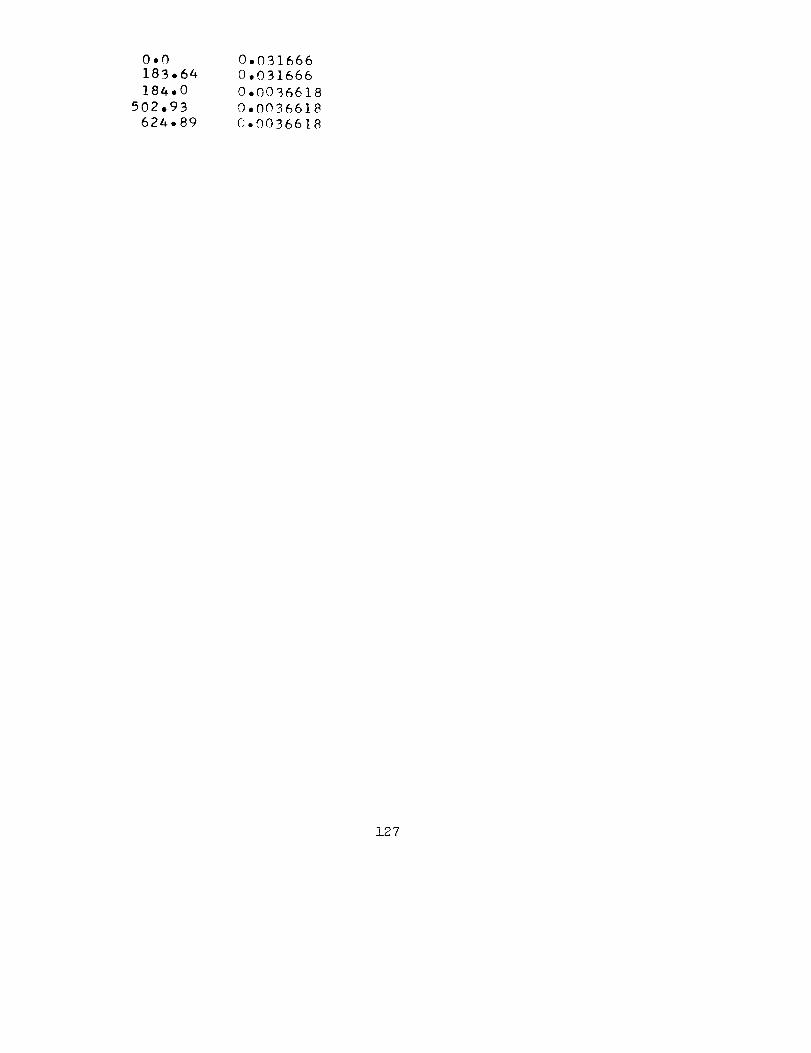
0.0
18B.64
184.0
502.9B
62A.89
0°031666
0,031666
0°0036618
0,0036618
0°0036618
127
