copy of 35174000 computer application in textiles 3 vig dhanabalan pavitra
TRANSCRIPT

8/6/2019 Copy of 35174000 Computer Application in Textiles 3 Vig Dhanabalan Pavitra
http://slidepdf.com/reader/full/copy-of-35174000-computer-application-in-textiles-3-vig-dhanabalan-pavitra 1/36
BASICS OF ONLINE MONITORING OF MACHINE AND PROCESS PERFROMANCE AT
DIFFERENT STAGES OF FABRIC PRODUCTION
The machine and process performance of the following stages of fabric production are monitored
online.
1. Cone winding
2. Warping
3. Sizing
4. Weaving
MODERN CONE WIDNING MACHINES
The modern highly automated cone winding department is faced with ever increasing
demands. Cross-wound packages with perfect winding-off qualities and long, knot free yarnlengths are required which in their size and form are adapted to the requirements of the
subsequent processes. Added to this are the requirements for consistently higher quality of the
wound yarn. Modern cone winding means constant optimizing of productivity while at the same
time achieving the required quality. The cone winding department is therefore almost ideally
suited for the on-line monitoring of quality and productivity at all production locations.
In weaving the weft accumulator unwinds yarn from a large weft supply packages and then
releases a precise amount to the weft insertion element of the loom.
Variations in winding tensions during fibre production are totally unacceptable as theslightest change in tension on the forming yarn will change its physical and dying properties.
The advent of splicing yarns means that ends may be joined in such a way that the
differences from the base yarn is virtually impossible to see. This has opened the way for
production of full size packages of knotless yarns being produced from part packages of what
once would have been simply waste. In a spinning plant this recovery can represent substantial
savings.
FULL CONE MONITORS
In cone winding, maintaining uniform and specified cone weight is major problem inalmost all the mills. Various methods are followed to maintain the cone weight. The weight
variations between cones, occurs mainly because of the variations in cop weight and also the
breakage between the cops. This problem has become acute after the introduction of electronic
clearers. This results in low cone winding productivity, weight complaints from the customers
and increased cost of production. Hence full cone monitor has become essential to manage the
above problems.

8/6/2019 Copy of 35174000 Computer Application in Textiles 3 Vig Dhanabalan Pavitra
http://slidepdf.com/reader/full/copy-of-35174000-computer-application-in-textiles-3-vig-dhanabalan-pavitra 2/36
Methods
1. Indicating ring
In manual cone winding machines, an attempt was made by providing ring in the
cone holder. When the cone touches this ring, the winder will doff the cone. This methodcauses damages or strains to the cone and hence was not successful.
2. Cyclic cop replenishment
Mills normally provide cone weight tolerance ranging from 10grams to 25 grams
for every cone. Hence, if the cop weight is maintained within plus or minus 2 grams and the
breakage rate is less than 2 per lakh meters, then the winders can follow cyclic cop
replenishment method, check our cone weight after attaining the specified size and doff all the
cones. If the variation between cops is high, then the winders have to spend not less than 0.5
minute for every cone by keeping all other drums idle by following winding and rewinding
method. When they do not wind, after weighing, it leads to cone defects.
3. Measuring discs
In this method, the yarn is passed over a measuring disc. The pulses from the disc are
converted into length and thus the cone is monitored. This system has not become
commercially successful because of high cost.
4. Template
Some mills use templates to measure the cone size and doff the full cones. The cone size
vary depending upon the climatic conditions, unwinding tension and winding tensiongiven to the yarn. Hence, this method has also failed.
AUTOMATIC DOFFER
• Doffing is carried out when the package reaches the pre-set meter age or diameter,
which can be set from 125 mm to 300 mm maximum.
• Auto doffing is carried out by one or two doffers.
• The doffers doff the package and deposits over the conveyor
• It restarts the heads
• These doffers are moved by a motor at a speed of 24 m/min on a track.
Operation Logic

8/6/2019 Copy of 35174000 Computer Application in Textiles 3 Vig Dhanabalan Pavitra
http://slidepdf.com/reader/full/copy-of-35174000-computer-application-in-textiles-3-vig-dhanabalan-pavitra 3/36
• When the metreage has reached, the winding head shuts down, actuates the trolley, arrest
transmitter and signal its conditions to the INSPECTOR CONTROL UNIT.
• The I.C instructs the trolley to move towards the head which is requesting a doff, as soon
as it reaches to the head and if all the conditions are ready then I.C. sends a doffing cycle
command to the trolley.
THE DOFFING CYCLE
1. Positioning of transfer tail and cutting of the yarn.
2. Opening of centre
3. Placement of roller on the moving centre to form the transfer tail.
4. Lifting of package holding arm to doffing position
5. Lifting of package
6. Tensioning of spring on the arm lifter
7. Lifting of yarn hook and scissor
8. Delivery of the tube between the centre
9. Actuation of package expulsion lever
10. Horizontal movement of the yarn hook.
Total time taken per cycle is 20 seconds. In 20 seconds, the above 9 steps are carried out with
respect to their timings only, but not in the same order.
YARN SPLICER
The splicer is designed for use in joining yarns where knots are either unacceptable or impossible
because of some special characteristics of the material itself.
SPLICING OPERATION
1. Yarn take-in
Push the upper and lower yarn into the splicer using the yarn guide levers, and then
clamp them there.
2. Cutting of the yarn ends
The upper and lower yarn cutters cut the ends of the upper and lower yarn

8/6/2019 Copy of 35174000 Computer Application in Textiles 3 Vig Dhanabalan Pavitra
http://slidepdf.com/reader/full/copy-of-35174000-computer-application-in-textiles-3-vig-dhanabalan-pavitra 4/36
3. Untwisting
The cut yarn ends are sucked into the untwisting nosily pipe and untwisted. At this time,
the yarn guide lever-R returns a little to allow a sufficient length of yarn to be twisted.
4. Splicing
The yarn guide lever-R is pushed in again, and it pulls the yarn ends out of the untwisting
nozzle. While the yarn ends are out they are held by the yarn holding lever, and a jet of
compressed air from the splicing nozzle tangles and twists the yarn ends together to
complete the splicing.
ELECTRONIC YARN CLEARER
Electronic yarn clearer functions either based on capacitance principle or photoelectric principle.
The setting is kept depending on the yarn count and the fault is identified based on the thickness
of the fault in the yarn and as well as the length of the fault.
The yarn is passed through the capacitors. Whenever there is variation in the yarn thickness and
also the length of the fault, the capacitance changes. This pulse is amplified and the knife is
activated by the sensitivity control and the yarn is cut.
The yarn passes through the light beam. Depending on the variation in the light intensity, the
photosensitive device gives the signal which is amplified and the knife is activated by the
sensitivity control and the yarn is cut.
WARPING
Warping is the process of winding warp threads on to a beam that can be used as the
warper’s beam in the further process of weaving. This is done with the help of a warping
machine. In this process the supply packages in the form of cones or cheeses are mounted on a
creel and the number of supply packages in the creel determines the number of ends in the beam.
The warp ends are fed in the form of a sheet wound on a beam in which all ends are parallel to
each other. Warping can be classified into direct beam warping and sectional warping. The of
control systems in this process is significant and directly influences the quality like the
appearance of the fabric that is finally woven in a loom. Warp specifications can be stored for
different parameters that are memorized by the PLC and can also be obtained even during power
failure. This PLC base control can also produce the data in a printout form. A Digital NumericalControl ensures that all beams are of the same length. It calculates the number of metres by
continuously measuring the circumference of the beam.
Controls in warping
1. Automatic Feed control system:
8/6/2019 Copy of 35174000 Computer Application in Textiles 3 Vig Dhanabalan Pavitra
http://slidepdf.com/reader/full/copy-of-35174000-computer-application-in-textiles-3-vig-dhanabalan-pavitra 5/36
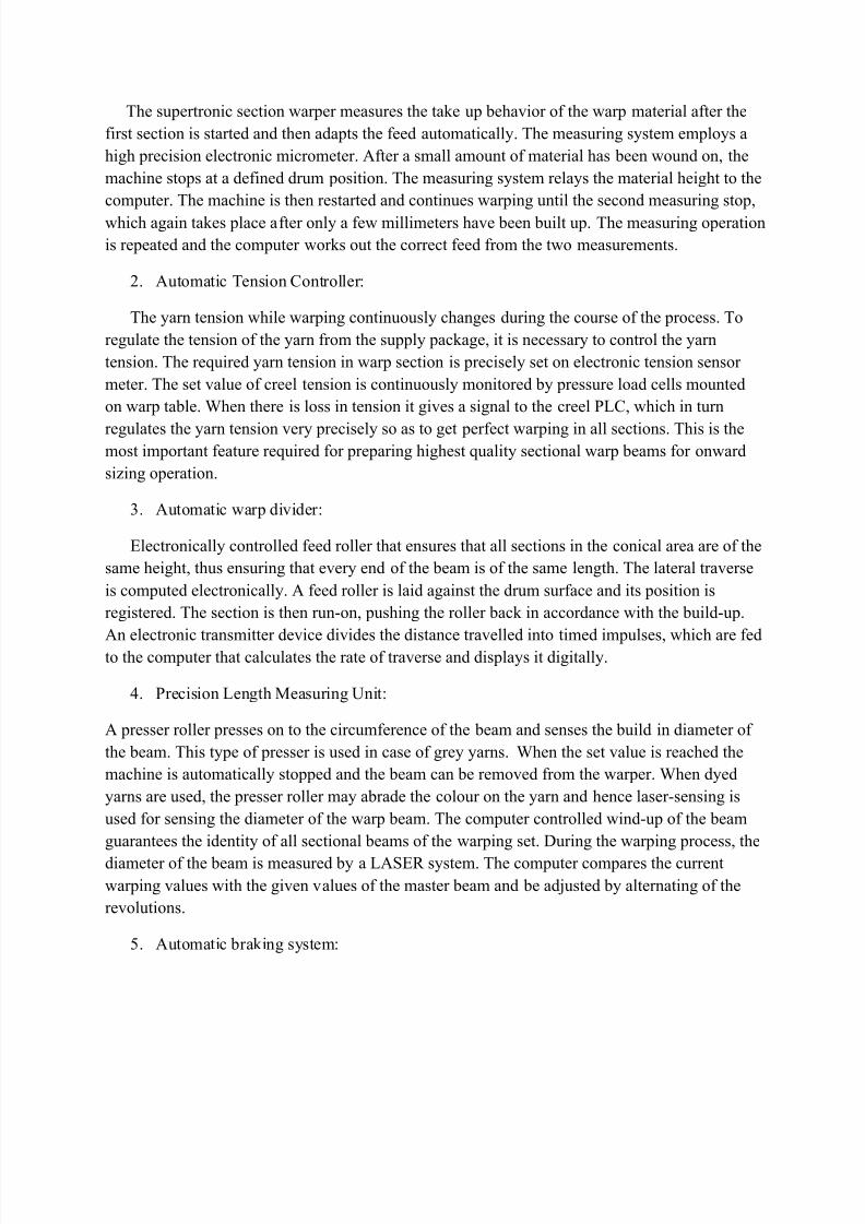
The supertronic section warper measures the take up behavior of the warp material after the
first section is started and then adapts the feed automatically. The measuring system employs a
high precision electronic micrometer. After a small amount of material has been wound on, the
machine stops at a defined drum position. The measuring system relays the material height to the
computer. The machine is then restarted and continues warping until the second measuring stop,
which again takes place after only a few millimeters have been built up. The measuring operation
is repeated and the computer works out the correct feed from the two measurements.
2. Automatic Tension Controller:
The yarn tension while warping continuously changes during the course of the process. To
regulate the tension of the yarn from the supply package, it is necessary to control the yarn
tension. The required yarn tension in warp section is precisely set on electronic tension sensor
meter. The set value of creel tension is continuously monitored by pressure load cells mounted
on warp table. When there is loss in tension it gives a signal to the creel PLC, which in turn
regulates the yarn tension very precisely so as to get perfect warping in all sections. This is themost important feature required for preparing highest quality sectional warp beams for onward
sizing operation.
3. Automatic warp divider:
Electronically controlled feed roller that ensures that all sections in the conical area are of the
same height, thus ensuring that every end of the beam is of the same length. The lateral traverse
is computed electronically. A feed roller is laid against the drum surface and its position is
registered. The section is then run-on, pushing the roller back in accordance with the build-up.
An electronic transmitter device divides the distance travelled into timed impulses, which are fedto the computer that calculates the rate of traverse and displays it digitally.
4. Precision Length Measuring Unit:
A presser roller presses on to the circumference of the beam and senses the build in diameter of
the beam. This type of presser is used in case of grey yarns. When the set value is reached the
machine is automatically stopped and the beam can be removed from the warper. When dyed
yarns are used, the presser roller may abrade the colour on the yarn and hence laser-sensing is
used for sensing the diameter of the warp beam. The computer controlled wind-up of the beam
guarantees the identity of all sectional beams of the warping set. During the warping process, the
diameter of the beam is measured by a LASER system. The computer compares the current
warping values with the given values of the master beam and be adjusted by alternating of the
revolutions.
5. Automatic braking system:

8/6/2019 Copy of 35174000 Computer Application in Textiles 3 Vig Dhanabalan Pavitra
http://slidepdf.com/reader/full/copy-of-35174000-computer-application-in-textiles-3-vig-dhanabalan-pavitra 6/36
Missing ends in the warp sheet can be avoided by using a braking system that has to function
during a thread break while warping. To achieve this control a powerful air cooled DISCBRAKE
on each side of drum is provided. The Hydro-pneumatic circuit present in this arrangement
ensures soft but extremely effective instantaneous braking during a warp brake. In addition, a
servo assisted hydro-pneumatic system helps to regulate brake pressure automatically for
uniform yarn winding on to the beam that can be mounted on the loom for weaving a fabric.
SIZING
Sizing is a very important process to produce warps for weaving. If size application can be
successfully controlled by the control system, the size application can be uniform without safety
reserves.
Controls in sizing are
1. Temperature control – It determines the viscosity of the size paste which plays a decisive
role which in turn determines the percentage of size pickup, size penetration and end
breakages during weaving.
2. Size level control – The electrically operated controlling device uses two electrodes
located in the size mixture. The electrode conductivity of the size paste itself provides the
basis for the application of the level control system. The system maintains the size level
within + or – 5 mm of the desired level.
3. Tension control on single end sizing – Each beam has a power brake impulse from the
beam tension controller. The power brake not only deal with emergency stops but
controls the creel tension by progressively reducing the braking torque as the beams arereduced in unwinding diameter.
4. Stretch control – The unit consists of two special transducers and the display unit. The
pulses generated by the transducers are processed by an electronic circuit and the result is
digitally displayed as percent stretch. The gadget is useful as it gives the operating stretch
instantaneously thus is facilitating corrective action wherever necessary.

8/6/2019 Copy of 35174000 Computer Application in Textiles 3 Vig Dhanabalan Pavitra
http://slidepdf.com/reader/full/copy-of-35174000-computer-application-in-textiles-3-vig-dhanabalan-pavitra 7/36
WEAVING
High speed weaving machines are equipped with precise positive monitoring devices with quick
response. The electromechanical and purely mechanical components are replaced by electronic
controls and monitoring devices. The automated controls used in weaving are the following.
1. Electronic shedding- Shedding is carried out by means of using servo motors.Electronic
shedding opens up completely new possibilities for producing ultra-fine,dense and
delicate fabrics of a quality never before achieved. As each shaft is controlled by servo
motor the movements of the shafts can be individually controlled. The crossing time and
duration of standstill can be programmed easily at the terminal.
2. Automatic Pick Controller ( APC)
The computer automatically sets all conditions for weft insertion according to the
weaving patterns and rpm set by the automatic initial condition setting (ICS) system.
Moreover, automatic adjustments are made to compensate for changes that occur
afterwards.
When a cheese change occurs, main pressure is momentarily increased via a by-
pass circuit at the main tank. With this system, not only is the wasteful consumption of
air is prevented, but also weft insertion is kept stable regarding of cheese changes. APC –
Main is extremely effective for filament weaving operations.
3. Warp Beam Let-off with Electronic control
Saurer developed automatic warp let-off motions of the ground and pile warps, by which
the two warps are let-off by drive motors. Control of these motors is performed by signals
from proximity switches fitted to levers of the suspended roller; the switching cycle of
the proximity switch is too small that on any slight change in the pre-selected warp
tension the warp let-off motor is switched on immediately for a short time.
4. Electronic Take-up motion
Weft density can be changed at will even while operation is in progress, making border
weaving possible for high grade handkerchiefs, etc.,
•All settings can be designated from the new function panel.
• Settings for up to 100 different patterns can be designated.
• Change – wheel changes are unnecessary, simplifying the weaving start – up
operation.

8/6/2019 Copy of 35174000 Computer Application in Textiles 3 Vig Dhanabalan Pavitra
http://slidepdf.com/reader/full/copy-of-35174000-computer-application-in-textiles-3-vig-dhanabalan-pavitra 8/36
Take –up torque is controlled according to the diameter of take-up cloth. The result is
constant cloth take-up tension. A multi-disc clutch provides stable cloth tension
regardless of the diameter of the take-up cloth.
5. Electronic weft detectors
On electronically controlled weaving machines the machine is no longer stopped by
awkward mechanical means but when weft is absent the detector fork produces an
electronic signal through a charge in the magnetic field. This is evaluated by the
electronic control and the machine is stopped in the desired position. The electronic
control can also switch on the automatic reverse and stop the machine in the open-shed
position when a weft thread breaks. Compared with the mechanical weft detectors the
reaction is appreciably quicker and adjustment and maintenance work is largely
unnecessary.
6. Electronic warp stop motion
The light beams are emitted in the shed by lamp, fixed at the reed, and lamp stationary
mounted on the machine frame. The two light sources are operated by a magnetic switch
within one part of the machine revolution as long as the shed is fully open. On the
opposite side of the warp sheet, photoelectric transistors are fitted on the reed and the
machine frame respectively.
This warp stop motion works when a warp end breaks or when spliced warp ends pass.
The luminous flux is disrupted and the weaving machine is stopped. This type of warp
stop motion is suitable for the weaving widths up to 4m. It is actually a contact less
checking of the shed cleanliness. The stop motion gives an outstanding reliability in the
silk and filament weaving. It appears that owing to the textile dust and fly connected with
the staple yarns of natural fibres as well as to the water spray connected with the water jet
weaving, it will be less reliable in the above two sectors.
7. The contact less warp protector motions
A weft carrier moves in the direction of screen and when it attains the exit position, the
light beam emits from the lamp and is directed towards the phototransistor. Disadvantage
of this system is that the stop motion fails to operate if the lamp is burnt or soiled.
According to modified design, the stop motion operates through two checking positions:
The screening of the light beam by the moving weft carrier between lamp and
photoelectric sensor is merely registered by the stop motion and the weaving is not
stopped.
When the weft carrier attains the exit position, the photoelectric sensor must again be
exposed to the light otherwise the weaving machine would be stopped. Both checks are

8/6/2019 Copy of 35174000 Computer Application in Textiles 3 Vig Dhanabalan Pavitra
http://slidepdf.com/reader/full/copy-of-35174000-computer-application-in-textiles-3-vig-dhanabalan-pavitra 9/36
interconnected so that when a short pick occurs or when the lamp filament is burnt, the
weaving machine is stopped.
A capacitance warp protector motion operates on the principle of the change of the sensor
capacitance caused by a metallic weft carrier attaining the exit position.
8. LOOMDATA
On line monitoring system employed in a loom , which monitors performance of the
loom and records the productivity of the loom as reports.
The configurations of the LOOMDATA system are
• Machine Entry station
• The production sensor
• Concentrator
• Bus Feed
• The central unit
• Terminals

8/6/2019 Copy of 35174000 Computer Application in Textiles 3 Vig Dhanabalan Pavitra
http://slidepdf.com/reader/full/copy-of-35174000-computer-application-in-textiles-3-vig-dhanabalan-pavitra 10/36
ELECTRONIC YARN CLEARER
Electronic yarn clearer is now firmly established as yarn fault detectors in all ordinary and
automatic cone winding machines. There are basically two principles namely;
Capacitance type:
Yarn
Block Diagram of Capacitance Type Electronic Yarn Clearer
The block diagram shows the principle of capacitance type electronic yarn clearer. In this
type, the yarn is passed through an air-spaced measuring condenser consisting of two parallel
plates with air as media. The yarn fault limits according to yarn cross-section, length and
spinners’s double are set by using suitable knobs in the instrument. As the yarn passes through
the capacitor , according to the length and cross section of the yarn, the capacitance value
changes. This is related to the mass of the material between the plates. The condenser measures
the material and electric signals are fed to an amplifier which amplifies the signals. The
amplified voltage is transferred to a discriminator which measures the pre-set fault limits. If the
signals exceed the limits, the signal is fed forward and through cutting impulse, a knife is
actuated to cut the yarn. A fibre type di-electric and sensitivity controls are used to get the
required sensitivity during the operation.
OSCILLATOR
SLUB SIZE
DISCRIMINATOR
KNIFE
ACTUATOR
SENSITIVITY
CONTROL
FIBRE TYPE
CONTROL
DIELECTRIC
AMPLIFIER
8/6/2019 Copy of 35174000 Computer Application in Textiles 3 Vig Dhanabalan Pavitra
http://slidepdf.com/reader/full/copy-of-35174000-computer-application-in-textiles-3-vig-dhanabalan-pavitra 11/36
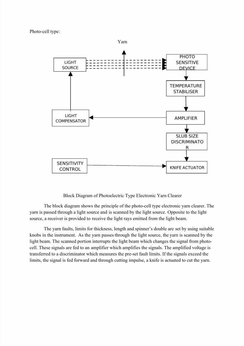
Photo-cell type:
Yarn
Block Diagram of Photoelectric Type Electronic Yarn Clearer
The block diagram shows the principle of the photo-cell type electronic yarn clearer. The
yarn is passed through a light source and is scanned by the light source. Opposite to the light
source, a receiver is provided to receive the light rays emitted from the light beam.
The yarn faults, limits for thickness, length and spinner’s double are set by using suitable
knobs in the instrument. As the yarn passes through the light source, the yarn is scanned by the
light beam. The scanned portion interrupts the light beam which changes the signal from photo-cell. These signals are fed to an amplifier which amplifies the signals. The amplified voltage is
transferred to a discriminator which measures the pre-set fault limits. If the signals exceed the
limits, the signal is fed forward and through cutting impulse, a knife is actuated to cut the yarn.
LIGHT
SOURCE
PHOTO
SENSITIVE
DEVICE
KNIFE
ACTUATOR
SLUB SIZE
DISCRIMINATO
R
AMPLIFIER
TEMPERATURE
STABILISER
LIGHT
COMPENSATOR
SENSITIVITY
CONTROL
LIGHT
SOURCE
KNIFE ACTUATOR
SLUB SIZE
DISCRIMINATO
R
AMPLIFIER
TEMPERATURE
STABILISER

8/6/2019 Copy of 35174000 Computer Application in Textiles 3 Vig Dhanabalan Pavitra
http://slidepdf.com/reader/full/copy-of-35174000-computer-application-in-textiles-3-vig-dhanabalan-pavitra 12/36
CONTROL SYSTEMS USED IN SIZING
If sensors and measuring instruments are used in the textile industry in the appropriate
manner, production process becomes safer and reproducibility is improved. This increases the
level of quality and productivity while reducing energy costs resulting in lower manufacturing
costs for any given textile material. To obtain these objectives sensors, measuring and controldevices are proposed.Sizing is a very important process to produce warps for weaving. If the size
application can be successfully controlled by the control system, the size application can be
uniform without safety reserves.
Modern sizing machines from SUKER, MULLER, BENNIGER, ZELL, TOYOTA are
having sensor controlled systems which monitor the process and operating condition and
maintain at set level, so the machine can run without stoppage and uniform size will be applied.
The following controls are employed in sizing
• Temperature control
• Size level control
• Automatic tension control on single end sizing
• Stretch control
• Size application measurement control
TEMPERATURE CONTROL
It determines the viscosity of the size paste which plays a decisive role which in turn
determines the following:
1. Percentage of size pickup
2. Size penetration
3. End breakages during weaving
The thermostat tube is inserted into the size paste through a hole on the side of the size box. It is
connected to the throttling valve by means of a capillary tube. The thermostat is equipped with atemperature setting unit which can be adjusted by means of a key at the end of the thermostat
tube. The throttling valve is situated in the steam supply line. A bypass arrangement is also
provided to supply the steam directly to the size box. In such cases the valves X and Y should
remain closed and the valve Z should be open. When temperature of the size mixture in the size
box reaches the predetermined degree, the fluid in the thermostat tube expands along the

8/6/2019 Copy of 35174000 Computer Application in Textiles 3 Vig Dhanabalan Pavitra
http://slidepdf.com/reader/full/copy-of-35174000-computer-application-in-textiles-3-vig-dhanabalan-pavitra 13/36
capillary tube and closes the throttling valve which has a double set ring thus cutting off the
steam supply
A: Thermostat tube D: Sieve
B: Throttle valve X, Y, Z: Valves
C: Capillary tube
When the temperature falls below the preset level due to the cutting off the steam supply, the
fluid in the capillary tube contracts and the spring at the top of the housing causes the valve to
open and allow the steam to pass from the supply line to the size box, once more.
SIZE LEVEL CONTROL
A, A’: Electrodes D: Relay
B: Diaphragm value E: Size box

8/6/2019 Copy of 35174000 Computer Application in Textiles 3 Vig Dhanabalan Pavitra
http://slidepdf.com/reader/full/copy-of-35174000-computer-application-in-textiles-3-vig-dhanabalan-pavitra 14/36
C: Electro-pneumatic relay G: Strainer
The electrically operated controlling device uses two electrodes located in the size mixture. The
electrode conductivity of the size paste itself provides the basis for the application of the level
control system. A slight difference between the electrodes prevents the system of cyclic opening
and closing of the size-flow value due to turbulence or foaming in the size box. When the sizelevel falls below the lower electrode the circuit is broken and the electro pneumatic relay is de-
energized and the air operated valve controlling the flow of the size paste is open. When the size
paste level rises and reaches the upper electrode the electric circuit is closed and the relay closes
the control valve.
The system maintains the size level within + or – 5mm of the desired level. The disadvantage of
this deposition of the size material on the electrode affects the working of the control device.
This problem can be overcome by coating the electrode with Teflon material. In the place of the
air operated control valve a solenoid operated control can also be used.
AUTOMATIC TENSION CONTROL ON SINGLE END SIZING
Section Beams Loom Beam
TG IM
TG PC MB
PB PB PB TG
Tension set Winding Tension set
Taper Tension set Speed set
PB- Power Brake M- Motor
PC – Power Clutch IM –Induction Motor
MB – Mechanical Brake TG – Tacho generator
Tension
Controlle
Speed
Controlle
r
Tension
Controlle
r
M
MM
M
M
TensionControlle
r
Speed
Controlle
r
Tension
Controlle
r

8/6/2019 Copy of 35174000 Computer Application in Textiles 3 Vig Dhanabalan Pavitra
http://slidepdf.com/reader/full/copy-of-35174000-computer-application-in-textiles-3-vig-dhanabalan-pavitra 15/36
The headstock is designed to operate at high speed of 140-150m/min. The winding
tension is also high. Each beam has a power brake impulse from the beam tension controller.the
power brake not only deal with emergency stops but controls the creel tension by progressively
reducing the braking torque as the beams are reduced in unwinding diameter. The draw roll in
the head stock is driven through a power clutch which is imposed from a second tension
controller. Both controller have independent settings and are interconnected and each separately
linked to the Tacho-generator. The creel power brakes are also capable of providing taper-
tension or tension gradient down the weaver’s beam.
STRETCH CONTROL
BTRA has recently developed a digital stretch meter specially designed for continuous
monitoring of percent stretch on sizing machines. The display unit along with the sensing units
consists of two special transducers and the display unit. One of the transducers is mounted on the
guide roller preceding the sow-box. The other transducer is placed on one of the rollers of the
drag roller assembly at the headstock. The pulses generated by the transducers are processed byan electronic circuit and the result is digitally displayed as percent stretch. The gadget is useful
as it gives the operating stretch instantaneously thus is facilitating corrective action whenever
necessary. One display unit can cater to three sizing machines, while a pair of transducers is
required separately for each machine. The salient features of this stretch meter are its fully solid
state circuitry, high accuracy and easily readable bright red display. The construction of the unit
is robust which help to withstand vibrations and hot humid conditions.
SIZE APPLICATION MEASUREMENT CONTROL
The moisture content of sized warp is measured continuously after the yarn passes through the
sizing trough and before the drier without contact and free of inertia by means of microwave
absorption. With constant size liquor concentration, a change in moisture content means an
immediate change in the degree of sizing.
Transducer
1
Display Unit
Electronic
Circuit Transducer
2
Guide roller Drag rollerSow-Box Headstock

8/6/2019 Copy of 35174000 Computer Application in Textiles 3 Vig Dhanabalan Pavitra
http://slidepdf.com/reader/full/copy-of-35174000-computer-application-in-textiles-3-vig-dhanabalan-pavitra 16/36
The microwave measuring heads are mounted on a stainless steel measuring frame. Since steam
clouds and high temperature occur behind the sizing trough, the measuring heads are protected
by a temperature controlled warm air cushion, a warm air unit producing hot air, which heats the
entire measuring frame and washes round each measuring head.
Measuring faults due to steam clouds are thus avoided and the measuring heads are protectedagainst too high temperature and condensation on the measuring frame and consequently
droplets on the fabric are prevented.
AS measurements can be processed visually with PLC for controlling squeeze roller pressure in
the sizing trough. In order to meet the special sizing requirements, special control algorithm have
been developed, guaranteeing a uniform degree of sizing at any time and thus maximum weaving
efficiency.
Size application is affected by numerous parameters.
• Speed
• Squeeze pressure
• Squeeze roller hardness
• Liquor temperature
The effect of all of this parameters can be identified on time with the size application meter AS.
Sizing can be largely uniform with consistent use of the AS 120 and size application control.
Sizing Trough Drier
AS
Digital
Display

8/6/2019 Copy of 35174000 Computer Application in Textiles 3 Vig Dhanabalan Pavitra
http://slidepdf.com/reader/full/copy-of-35174000-computer-application-in-textiles-3-vig-dhanabalan-pavitra 17/36
ONLINE MONITORING DEVICES IN WEAVING
1) Electronic Controls and monitoring devices on Shuttle weaving machines
The electromagnetic clutch and brake which are electronically controlled performs the
following functions
Switching ON and OFF
Slow forward and reverse running
Single pick control by push buttons
For precise control and monitoring, crank angle indicators necessary. They give information to
the electronic control of the machine position or give the signal at the time at which a process is
to be completed. The indicators are adjustable within certain limits. In order to reduce weaver
movement to the minimum, the push buttons are located at both ends of the machines on wider
machines additionally in the centre. Stop buttons at the back of the weaving machine provide for
stopping from these also. Three section warning lamps indicate the causes of stoppages so that
they may be remedied without a lengthy search.
Advantages of push button controls
Permits simple positive operation
Shorter training times
Shorter manual work for repairing weft thread breaks
Reduction in cloth faults as faulty operation is eliminated.
Shuttle flight monitoring:
The shuttle with attached permanent magnet passes over the left side sensor on entering the shed
from the left and on leaving the shed passes over the right hand sensor.
Sensor1 Sensor 2
These sensors each pass a signal to the electronic control which compares the actual time of the
shuttle with the set time of the impulse transmitter attached to the main shaft. When the time
does not agree ie., if the shuttle arrives at the right side sensor too easy or too late, the
electromagnetic brake is actuated through electronic control and the weaving machine is stopped.
Left RightShuttle
r

8/6/2019 Copy of 35174000 Computer Application in Textiles 3 Vig Dhanabalan Pavitra
http://slidepdf.com/reader/full/copy-of-35174000-computer-application-in-textiles-3-vig-dhanabalan-pavitra 18/36
Electronic Monitoring devices on Rapier weaving machines
Electronics are used on rapier machines primarily for weft monitoring. For rapier weaving
machines operating on the Dewas system (tip transfer), the piezoelectric monitoring system is
used for preference. The weft thread without any additional tensioning is passed at low angle
over the sensing unit. The start duration of monitoring are determined by the control system. TheLoepfe system consists of a stationary coil and a switching quadrant rotating with the weaving
machine crankshaft. A signal is thus produced by induction. Eltex uses a light cell for control
which operates in conjunction with a marker on the crankshaft as an electronic switch. On
electronic weft detectors for rapier weaving machines have shown that the required minimum
speeds for the positive functioning of the device on the Dewas weft insertion system is
dependent upon the following criteria.
1) The warp-round angle of the weft thread
2) The thread material
3) The yarn count and
4) The potentiometer setting
It was demonstrated that a certain “pressure” must be exerted on thread guide eye or the warp-
round pin for the weft detector to be able to register any thread movement. The following
advantages of electronic compared with mechanical weft yarn detectors may be quoted
Monitoring of weft yarns of all types over the full working width
No movable sensing parts
Simple mounting, adjustment and maintenance
Monitoring of single, double and multiple weft insertion, and
Low thread tension and no weft thread breaks in the centre of the cloth
Real time monitoring and planning for weave room
Real time machine monitoring and production reporting is still one of the primary functions of a
CIM system for a textile plant. Weave Master is a loom monitoring system. Through a GraphicalUser Interface(GUI), Weave master users are constantly informed about the actual situation in
the weave room resulting in faster reactions to problems and an increased efficiency. Powerful
analysis tools allows quick identification of poor performing machines and bottlenecks in
planning, resulting in an optimal usage of production capacities. With today’s small order
quantities and short delivery times, scheduling has become a critical function for the textile mill.
Weave Master offers the planning department an interactive tool allowing them to optimize loom

8/6/2019 Copy of 35174000 Computer Application in Textiles 3 Vig Dhanabalan Pavitra
http://slidepdf.com/reader/full/copy-of-35174000-computer-application-in-textiles-3-vig-dhanabalan-pavitra 19/36
loading based on real time information. Using the World Wide Web, the salesman can give
immediate and correct information about deliveries.
Color Mill:
The most important real time analysis tool of the Weave Master is the Color Mill. On this colour coded lay-out of the mill, the machines are pictured in a number of colour, each colour indicating
a certain machine status or alarm condition. From a data selection window, the user selects the
type of information to be displayed: efficiency, speeds, stop rates etc., For each data item,
exception limits can be defined and problem machines are automatically flagged. User definable
“filter sets” allow the user to display only these machines which correspond with a certain
condition, for example all machines with an efficiency less than 85%, all machines waiting for
an intervention, all machines weaving a specific style etc., A “mouse click” on a specific
machine opens a window with a detailed report showing all required information for the selected
machines. As a unique feature within Weave Master, these detail reports may contain any user
defined mixture of text and graphics.
Cockpit view:
The Cockpit view is the ultimate analysis tool for the plant manager and the industrial engineer.
Four graphs show the vital information needed to take quick decisions at the glance of just one
screen.
Film Report:
The film report is the result of an automatic machine activity sampling carried out by Weave
master. Based on user definable time intervals, the film report makes a complete machinediagonistic and shows whether efficiency loses were due to one long stop or were caused by
several short stops.
Electronic yarn tension control:
An additional tension meter allows you to quickly measure weft tensions accurately. The
portable and precise sensor is connected to the microprocessor of the machine. The tension
values are displayed as a graph, so that operator obtains the information needed to fine-tune and
control setting very fast. Fine-tuning and troubleshooting is easy thanks to the immediate
feedback. The results are repeatable and reproducible on other machines.
Using the tension meter will have a direct impact on productivity and quality. Each prewinder
can be equipped with a new type of Programmable Filling Tensioner (PFT). This PFT is
microprocessor-controlled and ensures optimum yarn tension during complete insertion cycle.
Reducing the basic tension is an important advantage when picking up weak yarns, while adding
tension is an advantage at transfer of the yarns and avoids the formation of loops. The tension
control enables you to weave strong or weak yarns at even higher speeds. It also drastically

8/6/2019 Copy of 35174000 Computer Application in Textiles 3 Vig Dhanabalan Pavitra
http://slidepdf.com/reader/full/copy-of-35174000-computer-application-in-textiles-3-vig-dhanabalan-pavitra 20/36
reduces the amount of filling stops, and enables you to set an individual waste length per channel
and reduce the waste length for some channels.

8/6/2019 Copy of 35174000 Computer Application in Textiles 3 Vig Dhanabalan Pavitra
http://slidepdf.com/reader/full/copy-of-35174000-computer-application-in-textiles-3-vig-dhanabalan-pavitra 21/36
LOOM DATA
The continuous supervision of the efficiency of all machines provides for immediate
determination of weaknesses which can then be corrected. A subdivision of down-times with
respect to short stops and longer out of the production times provides directives for instituting
systematic increase in machine output.
Lower stop frequencies
The automated and continuous control of the stop frequencies at each single machine makes
possible and immediate detection of outsider conditions, which can then be corrected. Many
comparison possibilities between separate machines and any number of selected machine groups
facilitate the determination of improved operating conditions and a means of reducing stop
frequencies step by step.
Improved Cloth Quality
Every mahine stop, very correction at the machine and every start position is a reason for a cloth
fault. A reduction of the stop frequency which can be achieved with the USA loomdata which
also represents a reduced amount of control at cloth inspection and lower of second quality
fabrics.
Purpose oriented use of Personnel
The activity of the over looker and the maintenance personnel is concentrated correcting
weakeness in the production process. The success of the measures undertaken checked by those
responsible in a simple manner.
Increased production speeds
Up –to- date information with respect to style-specific running conditions is the important pre-
requisite for an increased pick entry rate. The automatic nominalized comparison of the speeds
of all machines immediately indicates any deviations with machines.
Simplified Production Planning
Reliable mean values with reference to style-specific machine outputs and the determination of
production improvements facilitate production planning. Special reports the necessary survey
with respect to warps on stock and the warp-out prediction at the weaving machines.
Applications
• Quick achievement of optimum operating conditions after a style change
• Purpose oriented application of maintenance personnel instead of routine control
maintenance work.

8/6/2019 Copy of 35174000 Computer Application in Textiles 3 Vig Dhanabalan Pavitra
http://slidepdf.com/reader/full/copy-of-35174000-computer-application-in-textiles-3-vig-dhanabalan-pavitra 22/36
• Adaptation of the machine allocations per weaver to actual workload conditions.
• Shorter running –in-times for newly installed weaving machines and therefore an earlier
use of capital-intensive machinery.
•Avoidance of production losses as a result of missing warps or due to an unexpectedconcentration of warp change-over.
• Tracing out of long trends and achieved improvements by means of a simple graphical
representation of the more important characteristic data.
• Reduction in the number of styles by determining those styles which are being produced
under uneconomic conditions.
• Reduction of the warps on stack with the corresponding cost savings by means of an
improved survey and more accurate planning of warp manufacture
• Discontinuation of the reading of pick clocks and the manual methods of production
control
• Discontinuation of routine stop checks
• Determination of optimum operating conditions with respect to humidity and temperature
effects, the yarn material being applied , warp preparation, machine settings etc.,
• Further processing of the automatically determined production planning, calculations,
bonus systems, material control etc via a central computer system.
Configuration of loomdata
Machine entry
station
Production sensor
Concentrator
Central Unit
Bus Feed
Terminals

8/6/2019 Copy of 35174000 Computer Application in Textiles 3 Vig Dhanabalan Pavitra
http://slidepdf.com/reader/full/copy-of-35174000-computer-application-in-textiles-3-vig-dhanabalan-pavitra 23/36
Machine entry station monitors the important production datas such as efficiency etc.,
Production sensor:
The sensor determines the speed of a shaft which is rotating in proportion to the production.
From the revolving impulses, the following information is available via the weaving machine:
• Running/stop
• Efficiency in percentage
• Number, frequency and average duration of the shorts stops
• Out of production times
• Production speed
• Production amount
The production sensor has been arranged for the special ambient conditions encountered in
textile mills.
• The signal determination is undertaken by means of an inductive sensor and is therefore
not influenced by dust or dirt.
• The built-in light emitting diode signalizes the revolving impulses and provides for a
simple function control directly at the weaving machine.
Concentrator- The data are temporarily stored in the concentrator
Bus feed – It provides central current supply for the detection system
The Central Unit
The central unit is the heart of the LOOMDATA computer controlled data system. It fulfills
primarily the following functions:
• Periodic calling up of the concentrators and machine stations
• Continuous preparation and memorizing of the machine signals.
• Control of the dialogue with the user via the monitor and printer.
• Output of reports
• Output of pre-ordered data via the special on-line interface for further processing on and
central computer system

8/6/2019 Copy of 35174000 Computer Application in Textiles 3 Vig Dhanabalan Pavitra
http://slidepdf.com/reader/full/copy-of-35174000-computer-application-in-textiles-3-vig-dhanabalan-pavitra 24/36
• Control of the program timings via a built-in timer
• Determination of the allocation and control entire
The central unit is arranged according to the special requirements of a process data system
applied to weaving:
• The central unit is fully electronic and requires no special climatic conditions. It contains
neither parts which are sensitive to dust nor to wear such as ventilators, disc drives, etc.,
• The program cannot become lost as it is contained in fixed value memories (EPROM’S)
Terminals
This gives the most important production data as summarized reports known as standard reports.

8/6/2019 Copy of 35174000 Computer Application in Textiles 3 Vig Dhanabalan Pavitra
http://slidepdf.com/reader/full/copy-of-35174000-computer-application-in-textiles-3-vig-dhanabalan-pavitra 25/36
COMPUTER APPLICATI0NS IN WET PROCESSING
The first requirement in process control in textiles is to monitor the variable following
parameters
1) Temperature of the liquor
2) Flow rate
3) Level of Liquor and concentration
4) Pressure and PH value
The above parameters are controlled by
1) Electronically controlled valves
2) Motor drives
3) Pumps
4) Heating elements
5) Microprocessor based equipments
Functional diagram of process control system
In a wet processing unit the raw material which is fed is monitored and its datas are stored in the
computer. The process parameters like temperature, pressure, flow and speed are monitored and
controlled accordingly to get better productivity which can be tested in the final product.
Raw material
qualityTemperature Pressure Flow Speed
Product
quality
Computer
Wet Processing unit

8/6/2019 Copy of 35174000 Computer Application in Textiles 3 Vig Dhanabalan Pavitra
http://slidepdf.com/reader/full/copy-of-35174000-computer-application-in-textiles-3-vig-dhanabalan-pavitra 26/36
Microprocessor based chemical dosing system
Level sensor Level sensor Level sensor
Steam supply
Microprocessor based system to control various operation. The input details are fed into the
microprocessor control through the keyboard. The microprocessor with the software works and
controls the various operations in the dyeing unit. The hardware system involved here is
1) Micro computer unit
2) Various tanks
3) Motorized valves
4) Temperature and level sensors
5) Alarm which activates if anything goes beyond the set limits.
Water consumption control system
This system measures the rate of fabric being processed and calculates the volume of water. It
actuates the appropriate motorized control valve. If the water is full in the tank, the system
ensures to stop valves to stop the water flow. Conductivity and turbidity sensors are also utilized
to sense the level of the water while washing.
Alkali
Printer
Display
KeyboardMicroprocessor
Temperature sensor
Dye Salt

8/6/2019 Copy of 35174000 Computer Application in Textiles 3 Vig Dhanabalan Pavitra
http://slidepdf.com/reader/full/copy-of-35174000-computer-application-in-textiles-3-vig-dhanabalan-pavitra 27/36
Fabric
Water Overloading tank
Wet – on-wet control system
Microprocessor based instrument system can be utilized for better mercerization by monitoring
and controlling following parameters
1) Concentration of caustic solution (280g/l)
2) Liquor temperature which influences viscosity
3) Penetration time (35-50 sec,10-20ºC for cold mercerization and 25-35 sec,60-80ºC for
hot mercerization)
4) Tension of material
Computer Colour Matching
Colour matching is the art of reproducing the exact shade. Computer colour matching is the
science of predicting the recipe or the formula for exact shade reproduction.Visual colour
matching is subjective method whereas colour matching using Spectrophotometer is Objective
colour matching. This works under the optical principle.
When two samples match, their tristimulus value are identical . ie.,
X1=X2
Y1= Y2
Z1 = Z2
Where X, Y, and Z are the tristimulus values of coloured materials 1 and 2
Water control
system

8/6/2019 Copy of 35174000 Computer Application in Textiles 3 Vig Dhanabalan Pavitra
http://slidepdf.com/reader/full/copy-of-35174000-computer-application-in-textiles-3-vig-dhanabalan-pavitra 28/36
Usually when light is distributed from the source, the spectral power distribution of source is the
X value determined from the graph as
400 700 where X= K∑ PR x
λ (nm)
Y is the spectral reflectance of object and Z is reflectance of the observer which are shown in
the following graphs.
400 700 400 700
λ (nm) λ (nm)
where X= K∑ PR z where X= K∑ PR y
Colour mixing law
Colour mixing law is of three types
1. Additive colour mixing

8/6/2019 Copy of 35174000 Computer Application in Textiles 3 Vig Dhanabalan Pavitra
http://slidepdf.com/reader/full/copy-of-35174000-computer-application-in-textiles-3-vig-dhanabalan-pavitra 29/36
2. Subtractive colour mixing
3. Complex Subtractive mixing
Complex subtractive mixing:
When energy is removed from the incident beam by the process of absorption and scattering.
Kubleka –munk law is used to predict the colours obtained by complex subtractive colour mixing
As per Kubleka –munk function
Reflectance ∞ Concentration of solution
F(R)
Concentration %
Spectrophotometer is used to measure the reflectance value

8/6/2019 Copy of 35174000 Computer Application in Textiles 3 Vig Dhanabalan Pavitra
http://slidepdf.com/reader/full/copy-of-35174000-computer-application-in-textiles-3-vig-dhanabalan-pavitra 30/36
Flowchart of Computer colour matching
NO Yes
Yes No
Yes NO
Print out
Input Reflectance value of and X,
Y, Z standards
Choose three dyes from the datalist
Calculate dye concentrations C1,
C2, C3
Negative Concentration outside
tolerance limit
Compute X,Y,Z values for
three dyes
Calculate and compare with
standards
Calculate cost of dyeing
Print out

8/6/2019 Copy of 35174000 Computer Application in Textiles 3 Vig Dhanabalan Pavitra
http://slidepdf.com/reader/full/copy-of-35174000-computer-application-in-textiles-3-vig-dhanabalan-pavitra 31/36
Computer Colour Matching for fabric
Yes No
Customer Sample
Analyse Reflectance value by
spectrophotometer
Recipe suggested from computer
data(C1,C2, C3)
Production
department

8/6/2019 Copy of 35174000 Computer Application in Textiles 3 Vig Dhanabalan Pavitra
http://slidepdf.com/reader/full/copy-of-35174000-computer-application-in-textiles-3-vig-dhanabalan-pavitra 32/36
TEXTILE CAD
Technology is radically changing the relationship between the designer and the finished product.
As the work that occupies the space between the designer and consumer is now capable of being
totally automated, job functions, job descriptions and the entire product development and
production process are changing. Software simplify and streamline the endless repetition that gointo producing designs, revising size specifications, costing, infact the entire product
development process.
Textile CAD refers to products for Fabric Design. The software is not only meant to assist you in
design but also for further implementation to different production procedures. Apart from the
vast array of facilities, the three main applications of any of our products are
1. Research and Development of Design and Fabric
2. Production Planning and Implementation
3. Presentation for Marketing and sales
Design creation softwares
Some of the design creation software used are
• Adobe Photoshop
• Adobe Illustrator
•
Corel draw
• Photo Paint
• Micrografx picture publisher
• MS paint etc.,
Software Companies
• Textronics
• Wonder Weaves System
• Dream weavers
• TDS Jacquard
Software Development

8/6/2019 Copy of 35174000 Computer Application in Textiles 3 Vig Dhanabalan Pavitra
http://slidepdf.com/reader/full/copy-of-35174000-computer-application-in-textiles-3-vig-dhanabalan-pavitra 33/36
• Mostly VB, ASPL(Advanced Software Programming Language) are used for developing
softwares.
• CAD/CAM/CIM
Features of designing softwares
1. Colour mode- A colour mode determines the colour model used to display and
print images. Photoshop bases its colour modes on established models for
describing and reproducing colours. Common modes include HSD, RGB, CMYK.
2. Layout of designs- Layout determines the height and width of the designs to be
created. These layouts vary for different end uses. Approximately one pixel is
determined as one thread for Textile purpose. Therefore for Jacquard design
creation, initial layout creation varies according to the hook capacity of the
Jacquard.
3. Design creation using Tools
Tools in a software are the basic elements for creating a design. Tools vary from package to
package but their aim is to create a design effectively with less effort. The tools are classified as
Vector tools and bitmap design creation tools which are further classified as design creating and
design editing tools.
Ex. The move tool, The lasso tool, magic tool, crop tool.
4. Vector based designs
Vector designs are made up of lines and curves defined by mathematical objects called vectors.
Vectors describe an image according to its geometric characteristics.
5. Transformation of designs- Operations like to scale, rotate, skew, distort or apply are the
transformations performed in the design.
Scanning of fabrics and art works
A scanner captures images from fabrics, prints, poster, magazine pages and similar sources of
computers editing and display. Very high resolution scanner are used for scanning for high
resolution printers. Scanner usually come with Adobe’s Photoshop product.
GARMENT CAD
Richpeace Garment CAD system product series is of three types
1. Pattern design system (PDS)
8/6/2019 Copy of 35174000 Computer Application in Textiles 3 Vig Dhanabalan Pavitra
http://slidepdf.com/reader/full/copy-of-35174000-computer-application-in-textiles-3-vig-dhanabalan-pavitra 34/36
2. Garment Grading System (GGS)
3. Garment Marking System (GMS)
Pattern Design System (PDS)
• It has powerful and abundant pattern design tools.
• Free modifications and precise measurements
• Auto magnetic sizing enable you to locate each point accurately.
• Easy Darts shift
• Pieces overturn
• Copy
• Mirror
• Spread
• Modify
• Rotate
This system can be connected with scanner, plotter and printer.
PDS
Free Design Formula Design
Free Design:
It is easy to make the frame of your pattern in Richpeace. There are many professional
design tools which can help you draw and adjust your designs easily. It can help you draw the
corner of the pockets easily, merge darts. Curves can be adjusted or merged. The pattern can be
rotated.
Formula draw:
1. The system can record all formularies and measurements of each step in your design. So
that one can revise their design by one mouse click of the right button.

8/6/2019 Copy of 35174000 Computer Application in Textiles 3 Vig Dhanabalan Pavitra
http://slidepdf.com/reader/full/copy-of-35174000-computer-application-in-textiles-3-vig-dhanabalan-pavitra 35/36
2. Specifically, one can change the measure of each body part easily or create new size
easily by editing the measure and size again(Auto grading)
3. Intelligent: when one piece is adjusted, the other pieces related to it will be adjusted .
For example.when the armhole curve is adjusted, the sleeve will move together automatically.
Garment Grading System (GGS)
Providing point grading, line grading, regular grading and body grading. Editing the pattern input
through digitizer. Various and sufficient options for points, lines, curves, darts, pleats, notches
and shirring. There are also many modifications tools – False sewing, adding pleat, segment
duplication, spreading etc., wonder scale zooming and auto shrinking. Easily connect with
pattern design system and garment marking system and also can connect with different Input/
output equipments, such as digitizer, plotter and printer.
Garment Marking System (GMS)
Fully automatic and interactive marking methods. Multiple option settings enhance efficiency.
This system can give efficient marker. It can provide localizers with which patches can be
removed or rotated. The whole marker can be viewed and much more details can be obtained.
The plotter or printer can be used for outputting different scale marker.
Richpeace Garment CAD can connect with most of the popular plotter, digitizer, printer, cutter,
scanner etc., Usually, if one make patterns by themselves, a plotter is enough. If the patterns are
completed by others and you want to use the computer to get the different sizes and arrange themarker, then you need a digitizer and plotter.
Richpeace Digitizer
Overview- Richpeace digitizer is vey useful in all kinds of digital area, ie., Garment Industry.
Fashion Designing, Mapping, Mining, Punching and Environment Protection. It allows savings
most standard settings for more than 30 kinds of software in the option parameters set up and
supports about 30 kinds of digital formats. It is friendly, compatible and easy to connect with
most popular graphic applications ie., AutoCAD, Mapgis, Citystar, Mapinfo, Arcinfo,
Microstation, Supermap, Openinfo, Optitex, Arise, Billy, Cyber, GmCAD, Genemap, ViewGISetc.,
Standard features
1. Hardware interface Rs-232 serial Interface
2. Baud rate upto 19,200

8/6/2019 Copy of 35174000 Computer Application in Textiles 3 Vig Dhanabalan Pavitra
http://slidepdf.com/reader/full/copy-of-35174000-computer-application-in-textiles-3-vig-dhanabalan-pavitra 36/36
3. Output rate up to 100 pps
4. Technology Electromagnetic
5. Power Requirements 220V± 10% ,50Hz
Richpeace Plotter
Richpeace plotter which is supported by a wide range of popular CAD software, plots efficiency
on Textile papers, including Heat Seal and Brown paper of various widths from 1000mm up to
2000nm. The compact and reliable system works over unlimited length and provides a wide
selection of pen types ie., standard fibre tip plotter pen.
LECTRA
This the latest software used in Garment designing and following are the different modules used.
1. Modaris- This is used for pattern making
2. Dlamino – This is used for marker planning
3. Kalideo weave – This is used for Woven fabric
4. Kalideo Knit – This is used for knitted fabric
5. Kalideo Print - This is used for Printing and designing.