copyright © 2010 rockwell automation, inc. all rights reserved. instantaneous maintenance mode...
TRANSCRIPT
Copyright © 2010 Rockwell Automation, Inc. All rights reserved.
Instantaneous Maintenance Mode (IMM) MCCBs
(Confidential – For Internal Use Only) Copyright © 2010Rockwell Automation, Inc. All rights reserved. 2
Contents
1. Benefits
2. Applications
3. Product positioning
Copyright © 2010 Rockwell Automation, Inc. All rights reserved. 3
What is IMM
• MCCBs with IMM allow users another tool in mitigating the damage associated with Arc Flash in industrial control panels and Motor Control Centers.
• The IMM provides a separate maintenance mode, externally enabled which can be set to trip the breaker at currents from 2.5 to 4 times the breaker rating in approximately 30msec.
• IMM provides reduced response time to Arcing faults when compared to normal MCCBs adjusted for maximum coordination or to fuses.

Benefits of IMM MCCBs
• Faster reaction to Arcing Faults– Allowing less energy under arcing fault conditions– Resulting in less potential damage
• IMM Can be remotely engaged– Allows maintenance personal to enable the protection wearing PPE suitable for the
lower energy level.– Results in more productivity gains lost by not fully suiting up in some applications
• IMM offers second instantaneous trip settings– Provides ability adjust the breaker for maintenance conditions.– Provides improved Arc mitigation while adjustability reduces nuisance tripping
• Multiple confirmations provided with module.– Pilot light and separate hard contact provided.– Provides additional confirmation unit is in maintenance mode both locally or through
another output device.
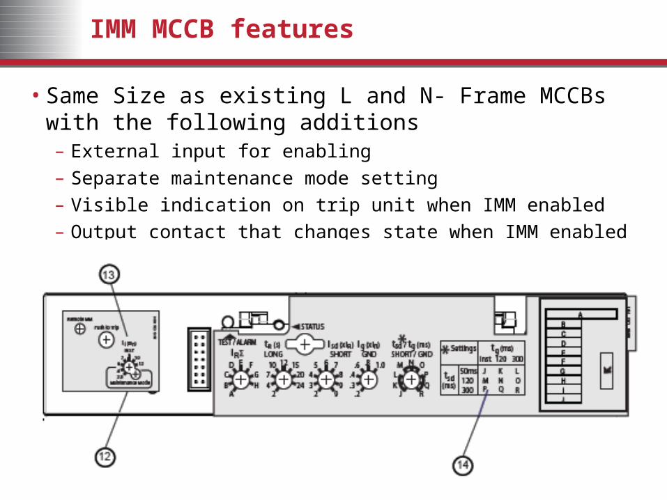
IMM MCCB features
• Same Size as existing L and N- Frame MCCBs with the following additions– External input for enabling– Separate maintenance mode setting– Visible indication on trip unit when IMM enabled– Output contact that changes state when IMM enabled
Why is an MCCB with IMM Important?
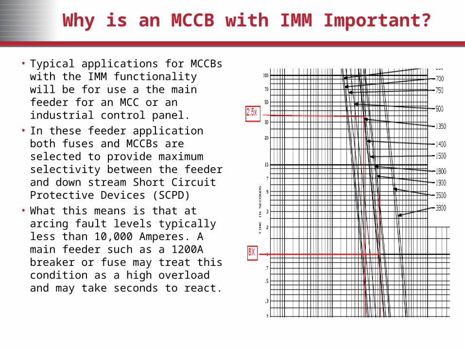
• Typical applications for MCCBs with the IMM functionality will be for use a the main feeder for an MCC or an industrial control panel.
• In these feeder application both fuses and MCCBs are selected to provide maximum selectivity between the feeder and down stream Short Circuit Protective Devices (SCPD)
• What this means is that at arcing fault levels typically less than 10,000 Amperes. A main feeder such as a 1200A breaker or fuse may treat this condition as a high overload and may take seconds to react.

Response time with IMM enabled
• MCCB’s with IMM enabled are able to react to fault levels at 2.5 or 4.0 x the rating of the breaker in 30msec or less.
• This feature allows the MCCB to be set in a more responsive state for conditions such as maintenance, providing an additional tool in mitigating the damage cause by Arcing faults, faster and better than they would be if they were set using their normal settings.
• The benefit is particularly useful when the arcing fault occurs between the feeder breaker and a branch SCPD, as under normal conditions the arcing current isn’t to a level that it would normally cause a fuse or MCCB to trip instantaneously.
Testing proves the benefits
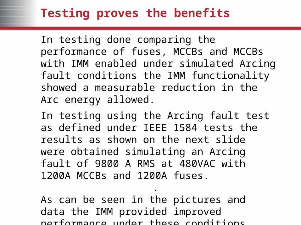
In testing done comparing the performance of fuses, MCCBs and MCCBs with IMM enabled under simulated Arcing fault conditions the IMM functionality showed a measurable reduction in the Arc energy allowed.
In testing using the Arcing fault test as defined under IEEE 1584 tests the results as shown on the next slide were obtained simulating an Arcing fault of 9800 A RMS at 480VAC with 1200A MCCBs and 1200A fuses.
.As can be seen in the pictures and data the IMM provided improved performance under these conditions when compared to a fuse or MCCB without IMM.

The Test results
The pictures below show the arc created using the IEEE 1584 test criteria . An actual Arcing fault is created what you see is the Arc and the calorimeter placed in front of the test to measure the energy let through by each of the devices
Results of test using 1200A fuseBrand X -Class L 1200A Fuse
Result: Fuse tripped at 771 ms, 15.7 kA peak
17.89 Calories/cm2
Results of Test using 1200A MCCB with IMM enabled IR=1200A,
Result: Breaker tripped at 18.7 ms, 16.8 kA peak
0.71 Calories/cm2
What do these test results mean?
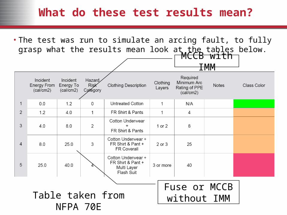
• The test was run to simulate an arcing fault, to fully grasp what the results mean look at the tables below.
MCCB with IMM
Fuse or MCCB without IMMTable taken from NFPA 70E

Taking the results to the next level
Hazard Risk Category 0
Hazard Risk Category 0
Hazard Risk Category 1
Hazard Risk Category 1 Hazard Risk
Category 2Hazard Risk Category 2
Hazard Risk Category 3
Hazard Risk Category 3
Hazard Risk Category 4
Hazard Risk Category 4Hazard Risk
Category 0Hazard Risk Category 0
Hazard Risk Category 1
Hazard Risk Category 1 Hazard Risk
Category 2Hazard Risk Category 2
Hazard Risk Category 3
Hazard Risk Category 3
Hazard Risk Category 4
Hazard Risk Category 4
PPE suggestions based upon NFPA 70E Hazard Risk Categories

IMM Trip Module Notes
• The test results and illustrations used in this presentation represent a specific example, it is critical that users have a qualified Arc Flash Analysis done to determine the Risk Category that exists in their application.
• A MCCB with IMM cannot eliminate arc faults, The IMM module is a tool in mitigation of the damage caused by arcing fault conditions.
• Ultimately the end user is responsible for establishing the risk category for their installation.
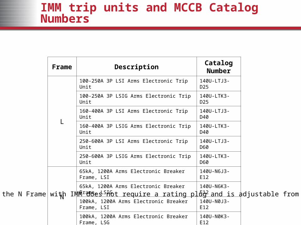
IMM trip units and MCCB Catalog Numbers
Frame DescriptionCatalog Number
L
100-250A 3P LSI Arms Electronic Trip Unit 140U-LTJ3-D25
100-250A 3P LSIG Arms Electronic Trip Unit 140U-LTK3-D25
160-400A 3P LSI Arms Electronic Trip Unit 140U-LTJ3-D40
160-400A 3P LSIG Arms Electronic Trip Unit 140U-LTK3-D40
250-600A 3P LSI Arms Electronic Trip Unit 140U-LTJ3-D60
250-600A 3P LSIG Arms Electronic Trip Unit 140U-LTK3-D60
N
65kA, 1200A Arms Electronic Breaker Frame, LSI 140U-N6J3-E12
65kA, 1200A Arms Electronic Breaker Frame, LSIG 140U-N6K3-E12
100kA, 1200A Arms Electronic Breaker Frame, LSI 140U-N0J3-E12
100kA, 1200A Arms Electronic Breaker Frame, LSG 140U-N0K3-E12
Note that the N Frame with IMM does not require a rating plug and is adjustable from 500 – 1200A

Support Materials
• Instructions Sheets– L Frame
• 40752-054 (2)• 40752-196 (1)
– N Frame• 40752-195 (1)
• Time Current Curves– L Frame
• 40752-744 (1)– N Frame
• 40752-745 (1)
• Selection tools– A117