corporate networking - univ-pau.frcpham.perso.univ-pau.fr/enseignement/vietnam/int... · –traffic...
TRANSCRIPT

CORPORATENETWORKINGC. PhamUniversité de Pau et des Pays de l’AdourDépartement Informatiquehttp://www.univ-pau.fr/[email protected]

Typical example Typical example of Ethernet local networksof Ethernet local networks
Mostly based on Ethernet: 10, 100, 1000 Mbps Multiple segments are interconnected with layer 2
switches or bridges

Collision Collision domaindomain

Collision Collision domaindomain
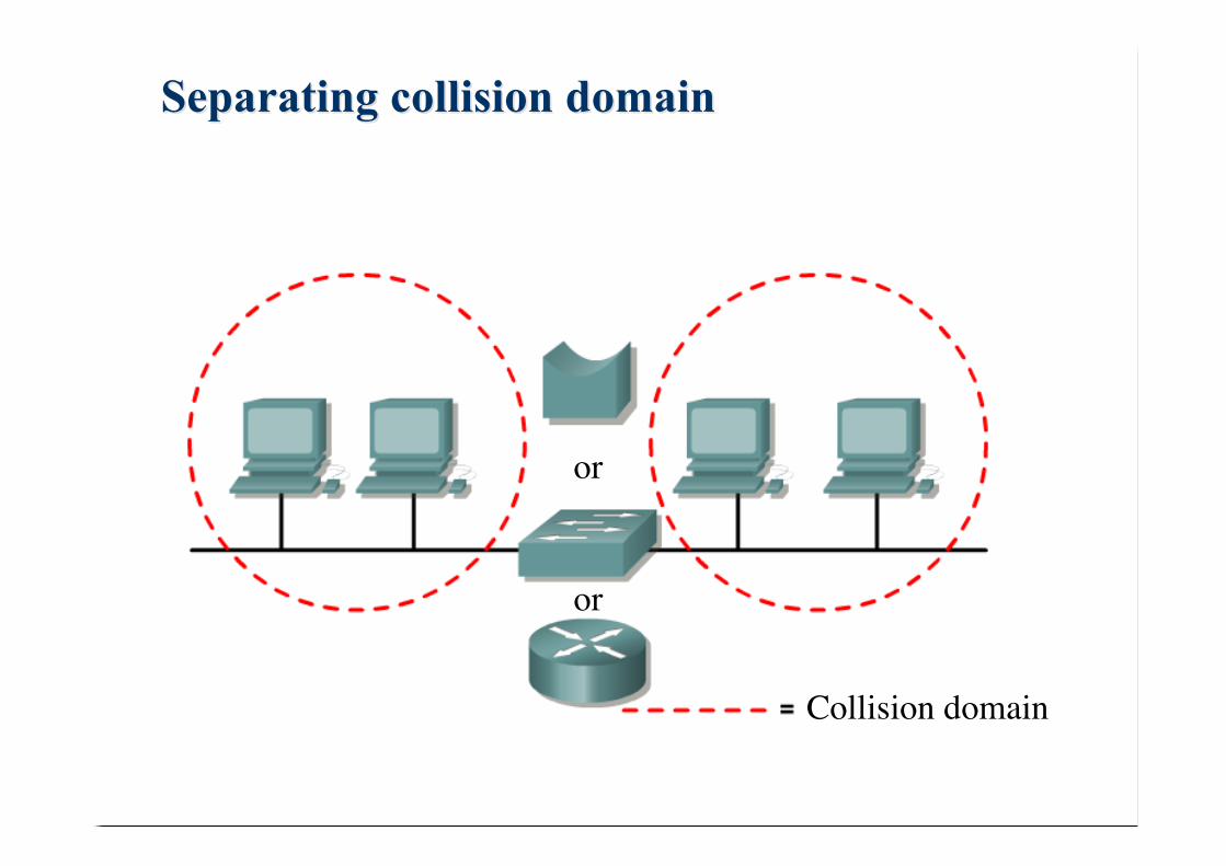
Separating Separating collision collision domaindomain
or
Collision domain
or

Segmentation Segmentation with with a bridgea bridge

Switched/Bridged LANsSwitched/Bridged LANs
Switched/bridged LANs– Are layer 2 devices that are able to forward specifically one
incoming frame to any output port, and only this one.
Bridge– Software based switching engine– Store & forward: about 50000 frames/s
Switch– Hardware based switching fabric (ASIC)– Store&forward, cut-through, fragment free: about 500000 frames/s– High density of ports– Half & Full duplex

Switch/bridge architectureSwitch/bridge architecture
switchingunit
controlprocessor
portDTE
FIFO
FIFO
FIFO
FIFO
CD Di Do CD Di Do CD Di Do CD Di Do
controldata
Shared mem

Redundant bridgingRedundant bridging
redundancy forreliability (failures)but addscomplexity.
source L. Toutain

source L. Toutain

Spanning Tree Protocol Spanning Tree Protocol (STP)(STP)
Brigdes will exchange messages in the form of:– Supposed id of the root (MAC addr.). At initialization, they assume
they are the root bridge– Supposed cost of the link. For a root bridge, the cost is zero.– Id of the sender.– Port number on which the msg is sent.
Algorithm for each bridge:– Search for the best msg (smallest root id first, then lowest cost,
then lowest sender’s addr, then smalest port) on all ports.– If a msg is better than configuration :
• This path becomes the path to the root. A new configuration is computed. Cost isincreased by 1.
• Ports that are between the best configuration and the newly computedconfiguration are deactivated. The other ports belongs to the spanning tree
• This configuration is sent on ports except those that lead to the root bridge
– If no msg is better that the one sent by a bridge B, B will consideritself as the root. source L. Toutain

Spanning Tree Protocol Spanning Tree Protocol (STP, IEEE 802.1d)(STP, IEEE 802.1d)
13,0,13,x
(id. root, cost, id. src, port)15,0,15,2
13,0,13,1 15,0,15,1
13,0,13,2
15,0,15,x 13,0,13,x
13,0,13,1
13,0,13,2
13,1,15,x
13,0,13,1
13,0,13,x
13,0,13,1
13,0,13,2
13,1,15,1
13,1,15,2
13,1,15,1
13,1,15,2
13,1,15,x
13,0,13,1
13,0,13,1 < 13,0,13,2 < 13,1,15,xthen disable port 2
best
calculated
best
calculated
best
calculated
best
calculated
best
calculated
best
calculated

Spanning treeSpanning tree, 4 networks, 4 networks
4,0,4,1
4,0,4,2
2,0,2,1
2,0,2,21,0,1,1
1,0,1,23,0,3,1
3,0,3,2
After a new 2nd phase of msg
1,1,3,2
1,1,2,1
1,1,2,1 < 1,1,3,2 < 1,2,4,xdisable port 2

Switched LANs vs RoutingSwitched LANs vs Routing
Well-known problems of switched/bridged LANs– Loops spanning tree protocol– High convergence time– Broadcast broadcast storm– Subnetworking– Limit to the smallest MTU of various LANs
What routers brings– Breaks up broadcast domains– Multicast control– Optimal path determination, fast convergence– Traffic management, redundancy and load balancing– Layer 3 addressing and hierarchical addressing– Advanced security– QoS

LAN inLAN in corporates corporates
Used the 80/20 rules: 80% of traffic is local, 20% oftraffic cross the corporate backbone– Network administrators made sure that all resources for the users
were contained within their own segment– Resources include: network servers, printers, applications
80%20%

The new 20/80 paradigmThe new 20/80 paradigm
Web-based applications, remote servers farms forvarious network services have created a newcommunication model where most of the traffic has tocross the corporate backbone
This new demand is putting a high load on routers:they must handle an enormous number of packets atwire speed
Handling 20/80 traffic model with layer 2 switchinghas lead to VLAN mechanisms– Virtual LAN: create logical groups of users– Support user’s mobility– Limits collision & broadcast domain, but still need router to route
between VLANs– Each VLAN runs its spanning tree

Segmenting in the old waySegmenting in the old way
IBM Compatible
IBM Compatible
IBM Compatible
Research
Teaching
Administration
IBM Compatible
Backbone
Location gives the subnetwork
Translated from Gille Rech

VLAN: Virtual LANVLAN: Virtual LAN
IBM Compatible
IBM CompatibleIBM Compatible
ResearchTeaching
TeachingAdministration
IBM Compatible
Research
BackboneTrunk

VLAN: Virtual LAN, on several switchesVLAN: Virtual LAN, on several switches
IBM Compatible
IBM Compatible IBM Compatible
Research
Teaching
Teaching
Administration
TrunkIBM Compatible
IBM Compatible IBM Compatible
Research
Teaching
Teaching

VLAN by port: segment-based VLANVLAN by port: segment-based VLAN
http://www.univ.edu.dj/cours/equipements/vlan.htm
Multiple VLAN on asingle port is difficult tomanage

VLAN by user-defined value: MAC addressesVLAN by user-defined value: MAC addresses
http://www.univ.edu.dj/cours/equipements/vlan.htm
MultipleVLAN/port ispossible, but needsfiltering and MACtable exchanges

VLAN by protocolsVLAN by protocols
http://www.univ.edu.dj/cours/equipements/vlan.htm
Only with routableprotocols

Built on 802.1D (transparent bridge) and 802.1p fortrunking VLANs
Dimensioning the VLAN Broadcast
– IP < 500 hosts– IPX < 300 hosts– Appletalk < 200 hosts
IEEE 802.1q VLANIEEE 802.1q VLAN

Core layer, layer 2 switches
Distribution layer, layer 3 switches/routers
Access layerLayer 2 switches
The classic 3-layer hierarchical modelThe classic 3-layer hierarchical model
Each layer withspecificfunctionalities
Layers can be logical

The core layerThe core layer
Responsible of transporting large amounts of traffic,common to a majority of users
The only purpose of the core is to switch traffic asfast as possible: routing is not mandatory (usually notrecommended)
Fault tolerance is an issue since a single failure couldaffect a large number of users, if not all
Design issues:– No acces lists, no VLANs and packet filtering– Avoid expanding the core size when the internetwork grows, give
preference to upgrades over expansion» Design the core for high reliability: FDDI, ATM, FastEthernet/GigaEth with
redundant links
– Select routing protocols with lower convergence time!

The distribution layerThe distribution layer
Sometimes referred to as workgroup layer The primary functions are to perform routing, filtering,
WAN access and policies for the networks Usually use routers or layer 3 switches Determine how packets access the core if needed The following things should be done:
– Implements access lists, packet filtering and queuing– Implements security and network policies, including address
translation and firewalls– Route between VLANs and other workgroup functions– Define broadcast and multicast domains

The distribution layer with minimal routingThe distribution layer with minimal routing
Scale well when VLANs are designed so that the majority ofresources are available in the VLAN (the 80/20 rule). If not,access to routing in the core is a problem

The distribution layer at low costThe distribution layer at low cost
Scaled switching is a low-cost and easy-to-install solution for a smallnetwork. Note that when VLANs are used, end users in one VLANcannot communicate with end users in another VLAN unless routersare deployed.
Access layerAccess layer
Continued (from distribution layer) access control andpolicies
Creation of separate collision domains (segmentation) Technologies such as switched Ethernet is frequently
seen in the access layer Static routing (instead of dynamic) is seen here as
well

Example of core blockExample of core block
core core
The core will usually not carry multiple subnet per link, thedistribution layer will: core is pass-through after routing hasbeen performed

Dual core exampleDual core example
core core
In this example, the 2 core are not connected, this allow forpreventing loops without STP, but need redundant linksfrom distribution layer routers to the core

Layer 2 or layer 3 core?Layer 2 or layer 3 core?
Core blocks are usually realized with layer 2 switchessince the core should only forward frames whenrouting has been done in the distribution layer
Layer 3 core may be needed for– Fast convergence: in layer 2 core, STP is used to prevent loops
(about 50s of convergence) . If the core is large, routing protocolhave faster convergence time
– Automatic load-balancing: with routing protocol in the core, multipleequal-cost links could be defined in the core, which is not easy tohave with (distribution)layer 3/(core)layer 2 model
– Elimination of peering problem: since routing is performed in thedistribution layer, each distribution layer device must keep“reachability” information to other distribution layer devices. Havinglayer 3 devices in the core creates a hierarchy. This scheme isusually realized when there are more than 100 switch blocks

What is the core size?What is the core size?
Routing protocols are the main factor in determiningthe core size: the convergence time of routingprotocol in the distribution layer
The routing protocol dictates the size of thedistribution layer devices that can communicate withthe core
15230RIP
25250EIGRP
25250OSPF
Max # ofsupportedblocks
# of linksto the core
Max # ofpeers
RoutingProtocol

Connecting Connecting corporates corporates to WANto WAN
Used to be leased lines (synchronous serialconnection, mostly for short distance connection)
Now: RNIS, xDSL, FR, ATM, SONET/SDH
Redondant WAN segment Multi-homing
RNIS, xDSL,FR, ATM…
E0 S0
S1
T1,E1
packetswitched
access distribution

DTE
DCE
EIA-232D (RS232-D)ITU-TSS (CCITT) V.24/V.28ISO 2110
ITU-TSS (CCITT) X.21ISO 4903
WAN connectorsWAN connectors
Uses serial transmission on twisted pair, coaxial,optical fiber…
Typical WAN connections are mainly based on HDLC,PPP, ISDN or Frame Relay data link layer.
See http://www.hardwarebook.net/connector/index.html#Serial
EIA-449, RS-449ISO 4902
ITU-TSS (CCITT) V.35

Some productsSome productsCisco SOHOEthernet, ADSL
Cisco 800Ethernet, ADSL,RNIS, Serial, VPN
Cisco 1700Ethernet, ADSL,T1/E1, FR, X25VLAN, VPN
CXR CyberConnect
CXR IX4100&4200