counter dan register - … · introduction circuits for counting events are frequently used in...
TRANSCRIPT

Counter dan Register

Introduction
Circuits for counting events are frequently used in
computers and other digital systems.
Since a counter circuit must remember its past
states, it has to possess memory.
The chapter about flip-flops introduced how flip-
flops are connected to make a counter.
The number of flip-flops used and how they are
connected determine the number of states and the
sequence of the states that the counter goes
through in each complete cycle.

Counters Classification
Counters can be classified into two broad
categories according to the way they are
clocked:
◦ Asynchronous (Ripple) Counters;
the first flip-flop is clocked by the external clock
pulse, and then each successive flip-flop is clocked
by the Q or Q' output of the previous flip-flop
◦ Synchronous Counters;
all memory elements are simultaneously triggered
by the same clock

Asynchronous (Ripple) Counters (two-
bits)
A two-bit asynchronous
counter is shown on the
right.
The external clock is
connected to the clock
input of the first flip-flop
(FF0) only.

Asynchronous (Ripple) Counters (two-bits)
FF0 changes state at the falling edge of each clock pulse,
but FF1 changes only when triggered by the falling edge
of the Q output of FF0.
Because of the inherent propagation delay through a flip-
flop, the transition of the input clock pulse and a
transition of the Q output of FF0 can never occur at
exactly the same time.
Therefore, the flip-flops cannot be triggered
simultaneously, producing an asynchronous operation.
Note that for simplicity, the transitions of Q0, Q1 and CLK in the timing diagram above are shown as
simultaneous even though this is an asynchronous counter. Actually, there is some small delay between
the CLK, Q0 and Q1 transitions.

Asynchronous (Ripple) Counters (two-bits)
The 2-bit ripple counter circuit above has
four different states, each one
corresponding to a count value.
Similarly, a counter with n flip-flops can
have 2 to the power n (2n) states.
The number of states in a counter is
known as its mod (modulo) number. Thus
a 2-bit counter is a mod-4 counter.

Asynchronous (Ripple) Counters (three-
bits)
It works exactly the same
way as a two-bit
asynchronous binary
counter mentioned
above, except it has eight
states due to the third
flip-flop.

Asynchronous Decade Counters
The binary counters previously introduced have
two to the power n (2n) states. But counters with
states less than this number are also possible.
They are designed to have the number of states in
their sequences, which are called truncated
sequences.
A common modulus for counters with truncated
sequences is ten. A counter with ten states in its
sequence is called a decade counter.

Asynchronous Decade Counters
Once the counter counts to ten (1010), all the flip-flops
are being cleared. Notice that only Q1 and Q3 are
used to decode the count of ten.
This is called partial decoding, as none of the other
states (zero to nine) have both Q1 and Q3 HIGH at
the same time.

Asynchronous Decade Counters
The sequence of the decade counter is shown in
the table below:

Asynchronous
Up-Down Counters
In certain applications a counter must be able to
count both up and down.
The circuit below is a 3-bit up-down counter. It
counts up or down depending on the status of the
control signals UP and DOWN.

Synchronous Counters
In synchronous counters, the clock inputs of all the
flip-flops are connected together and are triggered
by the input pulses.
Thus, all the flip-flops change state simultaneously
(in parallel).

Synchronous Counters

Synchronous Counters
The most important advantage of
synchronous counters is that there is no
cumulative time delay because all flip-flops
are triggered in parallel.
Thus, the maximum operating frequency
for this counter will be significantly higher
than for the corresponding ripple counter.

Synchronous Decade Counters
Similar to an asynchronous decade counter, a
synchronous decade counter counts from 0 to 9 and
then recycles to 0 again.
This is done by forcing the 1010 state back to the
0000 state.

Synchronous Decade Counters
From the sequence on the left, we notice that:
◦ Q0 toggles on each clock pulse.
◦ Q1 changes on the next clock pulse each time Q0=1 and Q3=0.
◦ Q2 changes on the next clock pulse each time Q0=Q1=1.
◦ Q3 changes on the next clock pulse each time Q0=1, Q1=1 and Q2=1 (count 7), or when Q0=1 and Q3=1 (count 9).

Synchronous Up-Down Counters
A circuit of a 3-bit synchronous up-down counter
and a table of its sequence are shown below.

Applications
Digital counters are very useful in many applications.
They can be easily found in digital clocks and parallel-to-serial data conversion (multiplexing).
A group of bits appearing simultaneously on parallel lines is called parallel data. A group of bits appearing on a single line in a time sequence is called serial data.
Parallel-to-serial conversion is normally accomplished by the use of a counter to provide a binary sequence for the data-select inputs of a multiplexer.
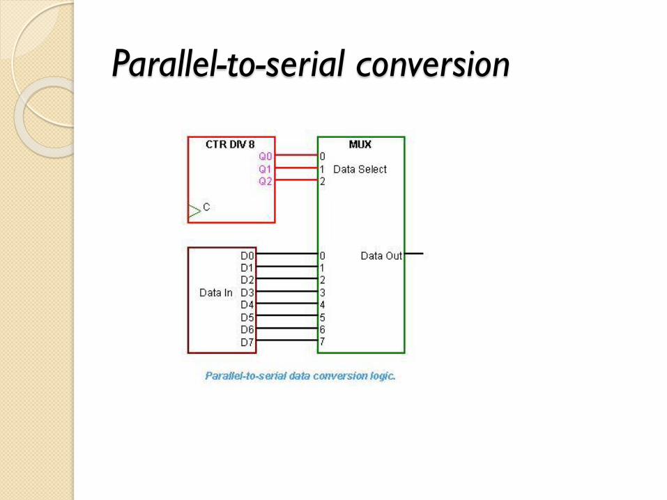
Parallel-to-serial conversion

Register Types
The basic types of shift registers
◦ Serial In - Serial Out
◦ Serial In - Parallel Out
◦ Parallel In - Serial Out
◦ Parallel In - Parallel Out
◦ bidirectional shift registers
A special form of counter - the shift
register counter

Serial In - Serial Out
Shift Registers (1) A basic four-bit shift register can be
constructed using four D flip-flops

Serial In - Serial Out
Shift Registers (2)
In order to get the data out of the register, they
must be shifted out serially
◦ destructive readout, the original data is lost and at the
end of the read cycle, all flip-flops are reset to zero

Serial In - Serial Out
Shift Registers (3)
To avoid the loss of data, an arrangement for a non-destructive reading can be done by adding two AND gates, an OR gate and an inverter to the system.
The data is loaded to the register when the control line is HIGH (ie WRITE).
The data can be shifted out of the register when the control line is LOW (ie READ).

Serial In - Parallel Out
Shift Registers
Data bits are entered serially
Once the data are stored, each bit appears on its
respective output line, and all bits are available
simultaneously

Parallel In - Serial Out
Shift Registers
The circuit uses D flip-flops and NAND gates for
entering data (ie writing) to the register
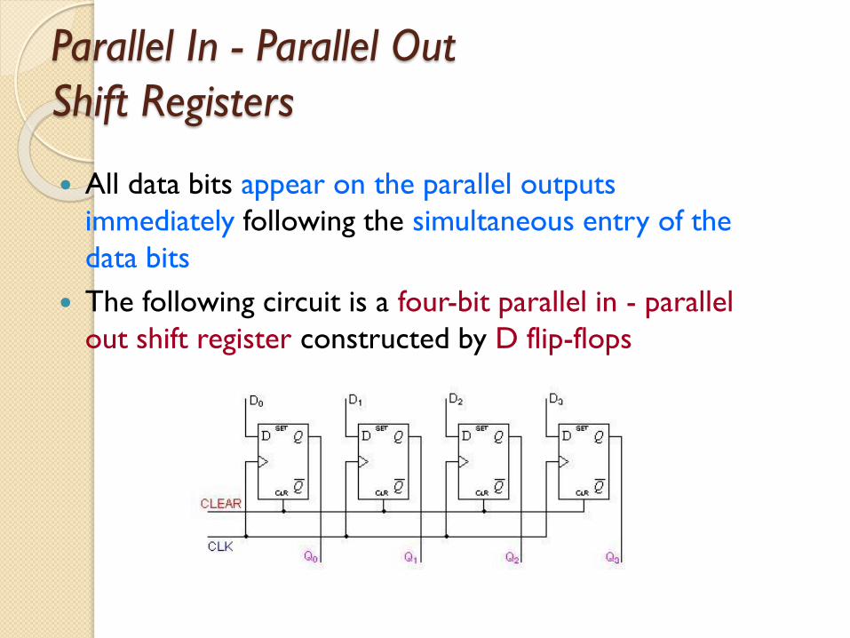
Parallel In - Parallel Out
Shift Registers
All data bits appear on the parallel outputs
immediately following the simultaneous entry of the
data bits
The following circuit is a four-bit parallel in - parallel
out shift register constructed by D flip-flops

Bidirectional
Shift Registers (1)
The registers discussed so far involved only right shift operations
Each right shift operation has the effect of successively dividing the binary number by two
If the operation is reversed (left shift), this has the effect of multiplying the number by two
A bidirectional, or reversible, shift register is one in which the data can be shift either left or right
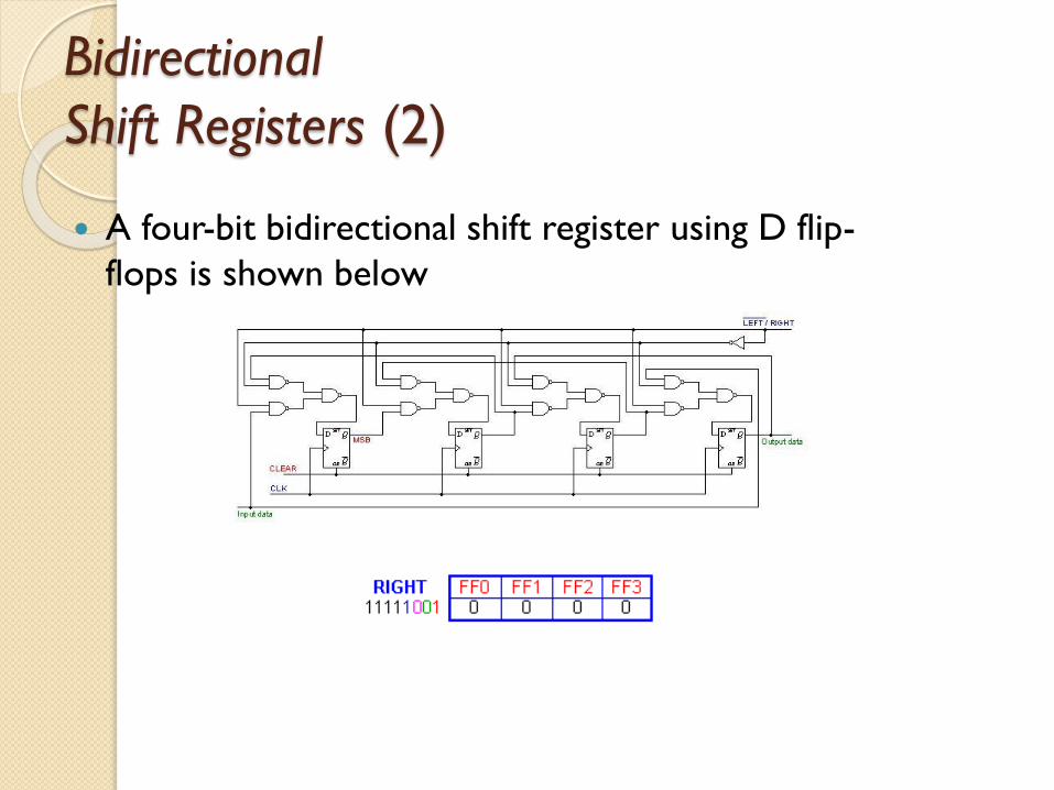
Bidirectional
Shift Registers (2)
A four-bit bidirectional shift register using D flip-
flops is shown below

Shift Register Counters
(Ring Counter)
A ring counter is basically a circulating shift register in
which the output of the most significant stage is fed
back to the input of the least significant stage

Shift Register Counters
(Johnson Counter)
Inverted output of the last stage fed back to the
input of the first stage
They are also known as twisted ring counters
Applications
To produce time delay
◦ The serial in -serial out shift register can be
used as a time delay device.
◦ The amount of delay can be controlled by:
the number of stages in the register
the clock frequency
To convert serial data to parallel data
◦ Use a serial in - parallel out register