coupled field finite element analysis of switched ...staff.jekman/peec/articles/getpdf13.pdf ·...
TRANSCRIPT
Coupled Field Finite Element Analysis of Switched Reluctance Motor with Soft Magnetic
Composite Material for Thermal Characterization K. Vijayakumar1, Member IEEE, R. Karthikeyan1, R. Arumugam2, Member IEEE, G. Premsunder3 and S. Kannan4
1Research scholars, 2 Retired Professor, Department of Electrical Engineering, Anna University, Chennai, India 3Senior Lecturer, Department of Electrical Engineering, Mailam Engineering College, TamilNadu, India
4Under Graduate Student, Mailam Engineering College, TamilNadu, India [email protected], [email protected], [email protected] and [email protected]
Abstract-This paper describes a more precise technique for thermal analysis due to joule heat loss in switched reluctance motor with soft magnetic composite material (SMC) by two dimensional (2-D) coupled field finite element analysis. The finite element model is solved in tandem by a cascaded procedure comprising electromagnetic and thermal analysis. The results of the coupled field finite element analysis of two configurations viz (a) Switched reluctance motor made of lamination sheet steel (SRM-M19) and (b) Switched reluctance motor made of soft magnetic composite material (SRM-SMC) are presented.
I. INTRODUCTION
The proliferation of power electronics technology with advances in material technology has led to the development of special machines for myriad applications in recent times. One of the special machines, the Switched Reluctance Motor (SRM) [1] is gaining recognition in the electric drives market due to its simple and rugged construction; low expected manufacturing costs, fault tolerance capability, high speed, high efficiency and high torque density. Innovative practices in powder metallurgy technology has led to the development of Soft Magnetic Composite (SMC) materials that have unique properties [2]-[3], which include three dimensional (3D) isotropic ferromagnetic behavior, very low eddy current loss, relatively low total iron loss at medium and high frequencies, possibilities for improved thermal and vibration characteristics, flexible machine design and assembly and a prospect for greatly reduced production cost. One of the possible approaches is to replace the classical laminated magnetic circuit of electric machines made from silicon iron sheets with soft magnetic composite or iron powder material. The results of using these materials are shorter magnetic circuit manufacturing time, a smaller number of components and less scrap. Electromagnetic field analysis has been developed for motor design and thermal fields are often a separate problem for electromagnetic devices, like electric motors. Therefore the coupled calculations of thermal and electromagnetic fields become essential for electric motors, like switched reluctance motor. Thus temperature analysis of two configurations viz a) SRM made of Sheet Steel (SRM-M19) and (b) SRM made of Soft Magnetic Composite material (SRM-SMC) has been presented in this paper.
When developing and optimizing motor drives calculation of the losses are desirable. These losses are often the cause of temperature rise in the motor. The losses in SRM comprise electrical and mechanical losses. This paper focuses on joule heat loss (copper loss). The loss distributions [4] are obtained from the electromagnetic coupled field analysis. The outline of this analysis is indicated in Fig. 1.
II. SWITCHED RELUCTANCE MOTOR
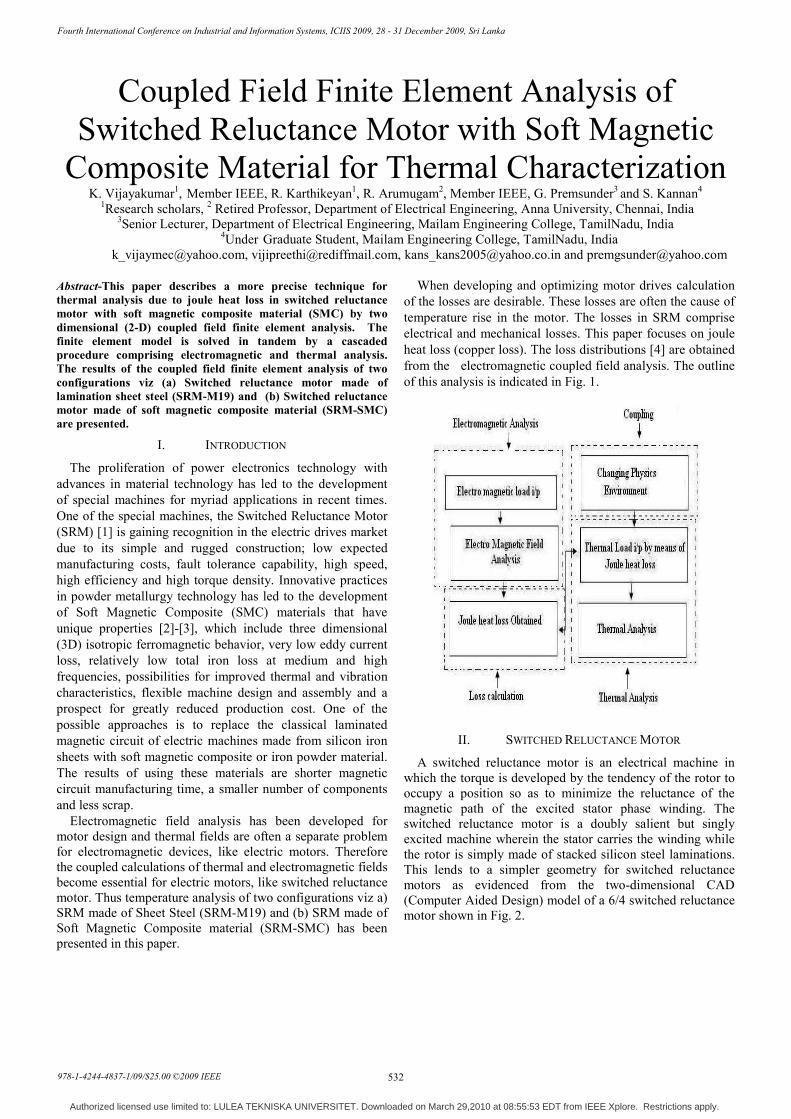
A switched reluctance motor is an electrical machine in which the torque is developed by the tendency of the rotor to occupy a position so as to minimize the reluctance of the magnetic path of the excited stator phase winding. The switched reluctance motor is a doubly salient but singly excited machine wherein the stator carries the winding while the rotor is simply made of stacked silicon steel laminations. This lends to a simpler geometry for switched reluctance motors as evidenced from the two-dimensional CAD (Computer Aided Design) model of a 6/4 switched reluctance motor shown in Fig. 2.
Fourth International Conference on Industrial and Information Systems, ICIIS 2009, 28 - 31 December 2009, Sri Lanka
978-1-4244-4837-1/09/$25.00 ©2009 IEEE 532
Authorized licensed use limited to: LULEA TEKNISKA UNIVERSITET. Downloaded on March 29,2010 at 08:55:53 EDT from IEEE Xplore. Restrictions apply.
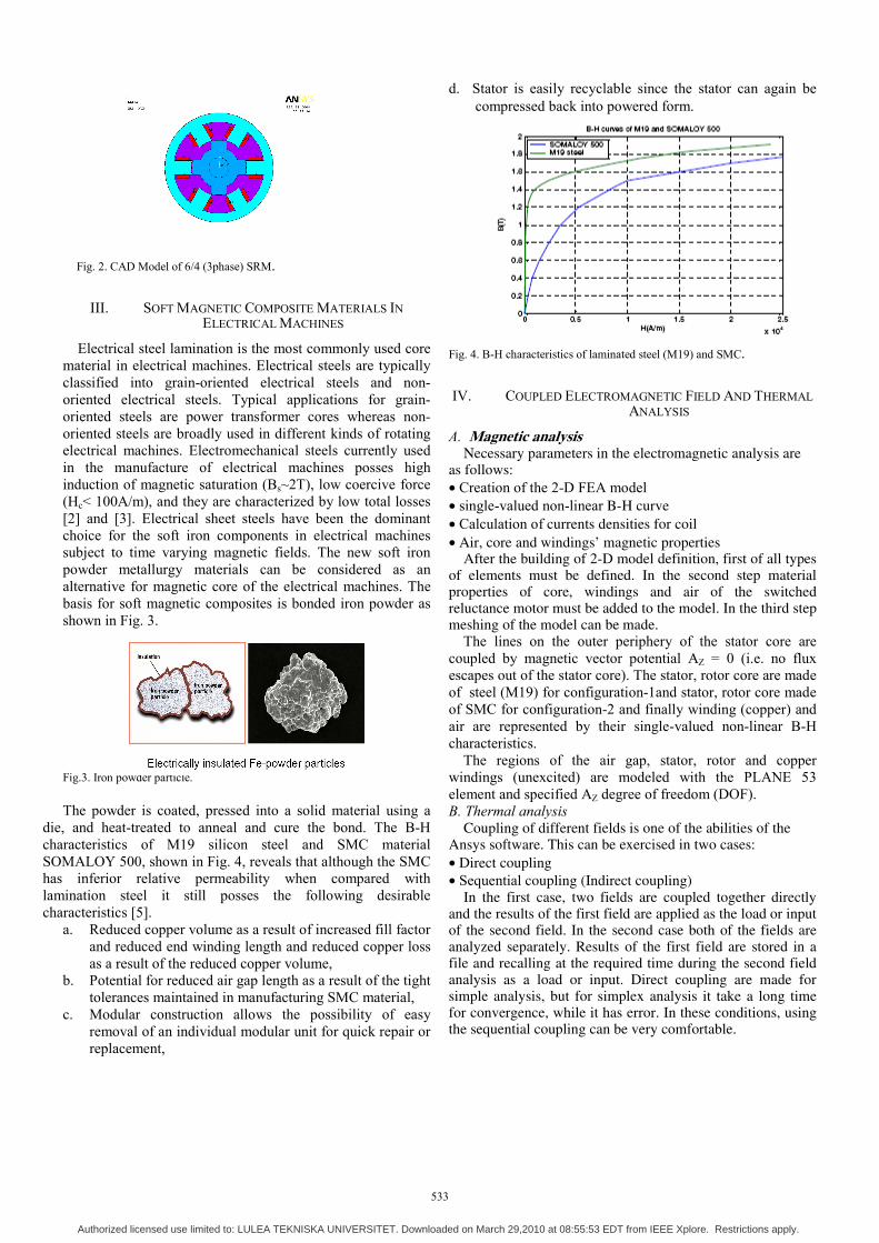
Fig. 2. CAD Model of 6/4 (3phase) SRM.
III. SOFT MAGNETIC COMPOSITE MATERIALS IN ELECTRICAL MACHINES
Electrical steel lamination is the most commonly used core material in electrical machines. Electrical steels are typically classified into grain-oriented electrical steels and non-oriented electrical steels. Typical applications for grain-oriented steels are power transformer cores whereas non-oriented steels are broadly used in different kinds of rotating electrical machines. Electromechanical steels currently used in the manufacture of electrical machines posses high induction of magnetic saturation (Bs~2T), low coercive force (Hc< 100A/m), and they are characterized by low total losses [2] and [3]. Electrical sheet steels have been the dominant choice for the soft iron components in electrical machines subject to time varying magnetic fields. The new soft iron powder metallurgy materials can be considered as an alternative for magnetic core of the electrical machines. The basis for soft magnetic composites is bonded iron powder as shown in Fig. 3.
Fig.3. Iron powder particle.
The powder is coated, pressed into a solid material using a die, and heat-treated to anneal and cure the bond. The B-H characteristics of M19 silicon steel and SMC material SOMALOY 500, shown in Fig. 4, reveals that although the SMC has inferior relative permeability when compared with lamination steel it still posses the following desirable characteristics [5].
a. Reduced copper volume as a result of increased fill factor and reduced end winding length and reduced copper loss as a result of the reduced copper volume,
b. Potential for reduced air gap length as a result of the tight tolerances maintained in manufacturing SMC material,
c. Modular construction allows the possibility of easy removal of an individual modular unit for quick repair or replacement,
d. Stator is easily recyclable since the stator can again be compressed back into powered form.
Fig. 4. B-H characteristics of laminated steel (M19) and SMC.
IV. COUPLED ELECTROMAGNETIC FIELD AND THERMAL ANALYSIS
A. Magnetic analysis Necessary parameters in the electromagnetic analysis are as follows: • Creation of the 2-D FEA model • single-valued non-linear B-H curve • Calculation of currents densities for coil • Air, core and windings’ magnetic properties After the building of 2-D model definition, first of all types of elements must be defined. In the second step material properties of core, windings and air of the switched reluctance motor must be added to the model. In the third step meshing of the model can be made. The lines on the outer periphery of the stator core are coupled by magnetic vector potential AZ = 0 (i.e. no flux escapes out of the stator core). The stator, rotor core are made of steel (M19) for configuration-1and stator, rotor core made of SMC for configuration-2 and finally winding (copper) and air are represented by their single-valued non-linear B-H characteristics. The regions of the air gap, stator, rotor and copper windings (unexcited) are modeled with the PLANE 53 element and specified AZ degree of freedom (DOF). B. Thermal analysis Coupling of different fields is one of the abilities of the Ansys software. This can be exercised in two cases: • Direct coupling • Sequential coupling (Indirect coupling) In the first case, two fields are coupled together directly and the results of the first field are applied as the load or input of the second field. In the second case both of the fields are analyzed separately. Results of the first field are stored in a file and recalling at the required time during the second field analysis as a load or input. Direct coupling are made for simple analysis, but for simplex analysis it take a long time for convergence, while it has error. In these conditions, using the sequential coupling can be very comfortable.
533
Authorized licensed use limited to: LULEA TEKNISKA UNIVERSITET. Downloaded on March 29,2010 at 08:55:53 EDT from IEEE Xplore. Restrictions apply.

In this analysis for simplicity sequential coupling of electromagnetic and thermal fields are used. Output of the electromagnetic analysis is directly applied as input to the thermal analysis as the load. Fig. 5, shows distribution of the joule heat loss at rated current of 13A. This joule heat loss forms the heat flux for the thermal problem. C. Numerical conditions
TABLE I THE NUMERICAL CONDITIONS FOR COUPLED ELECTROMAGNETIC-THERMAL
ANALYSIS
Coupling method Sequentially coupled method
Shape of element Quadrilateral Element type Plane 53&Plane 77
Characteristics of the material Non linear Type of analysis Two stage Step time (sec) 300
Fig. 5. Distribution of joule heat loss. V. RESULTS AND DISCUSSION
The steady state and transient temperature distribution obtained when the temperature distribution is non-uniform at 13A in the coupled electromagnetic thermal analysis for two configurations SRM-M19 and SRM-SMC is shown in Figs. 6-9. The calculated result of temperature rise at the midpoint of the stator pole, at the mid point of the stator winding and the mid point of the rotor at 13A for two configurations by coupled magnetic thermal analysis is shown in Figs. 10-15. The thermal analysis results indicate that SRM-SMC (configuration-2) has improved heat dissipation (heat removal) capacity which is also evident from Table II.
Fig.6. Non uniform temperature distribution by coupled magnetic thermal analysis in 300 sec for SRM-M19.
Fig.7. Steady state temperature distribution by coupled magnetic thermal analysis for SRM-M19.
Fig.8. Non uniform temperature distribution by coupled magnetic thermal analysis in 300 sec for SRM-SMC.
Fig.9. Steady state temperature distribution by coupled magnetic thermal analysis for SRM-SMC.
Fig. 10. Temperature rise at the midpoint of the stator pole with coupled magnetic thermal analysis for SRM-M19.
534
Authorized licensed use limited to: LULEA TEKNISKA UNIVERSITET. Downloaded on March 29,2010 at 08:55:53 EDT from IEEE Xplore. Restrictions apply.

Fig. 11. Temperature rise at the midpoint of the stator winding with coupled magnetic thermal analysis for SRM-M19.
Fig.12. Temperature rise at the midpoint of the rotor with coupled magnetic thermal analysis for SRM-M19.
Fig.13. Temperature rise at the midpoint of the stator pole with coupled magnetic thermal analysis for SRM-SMC.
Fig.14. Temperature rise at the midpoint of the stator winding with coupled magnetic thermal analysis for SRM-SMC.
Fig. 15. Temperature rise at the midpoint of the rotor with coupled magnetic thermal analysis for SRM-SMC.
TABLE II
THE TEMPERATURE DISTRIBUTION BETWEEN TWO CONFIGURATIONS
* Temperatures are in Kelvin
VI. CONCLUSION
The temperature rise due to joule heat loss in SRM with soft magnetic composite material is presented by means of 2-D coupled field finite element analysis. It is observed that the SRM-SMC configuration renders improved thermal heat dissipation when compared with SRM-M19 configuration in the high-speed applications regime.
REFERENCES [1] R. Arumugam, D. A. Lowther, R. Krishnan and J. F. Lindsay,
“Magnetic field analysis of a switched reluctance motor using a two dimensional finite element model,” IEEE Trans. Magn., vol. MAG-21, no. 5, pp. 1883-1885, Sep. 1985.
[2] M. Persson, P. Jansson, A. G. Jack, B. C. Mecrow, “Soft Magnetic Composite Materials – Use for Electrical Machines”; 7th International Conference on Electrical Machines and Drive at Durham, England, Sep. 1995.
[3] A.G. Jack, “Experience with the Use of Soft Magnetic Composites in Electrical Machines”, International Conference on Electrical Machines, Istanbul, Turkey, 1998, pp. 1441-1448.
[4] Shingo Inamura, Tomokazu Sakai and Koichiro Sawa, "A temperature rise analysis of switched reluctance motor due to core and copper losses by FEM," IEEE Trans. Magn.,, vol. 39, no. 3, pp. 1554-1557, May 2003.
[5] “The Latest Development in Soft magnetic Composite Technology from Hoganas Metal Powders”, Hoganas Manual, 1999-2003.
[6] J. P. Holman, Heat Transfer. New York: McGraw-Hill, 1986. [7] Ansys Software Documents, Version 9.0, 2004.
Name of the configurations
Steady state analysis Transient analysis
Min temp
Max temp
Min temp
Max temp
SRM-M19 281 312 21 311 SRM-SMC
257 312 32 311
535
Authorized licensed use limited to: LULEA TEKNISKA UNIVERSITET. Downloaded on March 29,2010 at 08:55:53 EDT from IEEE Xplore. Restrictions apply.