course 1 a general view on the fixed telephone network...
TRANSCRIPT
Course 1A general view on the fixed telephone network. Digital
networks. General aspects. Definitions.
Zsolt Polgar
Communications Department
Faculty of Electronics and Telecommunications,
Technical University of Cluj-Napoca
Content of the course
� A general view on the fixed telephone networks;
� Basic aspects concerning the switching techniques;
� IDN networks and the evolution toward ISDN;
� Terms and definitions used for describing the fixed telephone networks;
Year 2015 – 2016
Semester IITelephony 2

A general view
� The telephone networks:
� communication network dedicated to voice transmission;
� the network parameters are adapted to the offered service;
� frequency bands;
� signal processing;
� delays;
� the network must ensure the transmission of the voice signal
between two or more subscribers with a given quality of the
service:
� signal to noise/ratio;
� distortion level;
� delays;
� waiting time for connection;
� connection rejection probability;
Year 2015 – 2016
Semester IITelephony 3
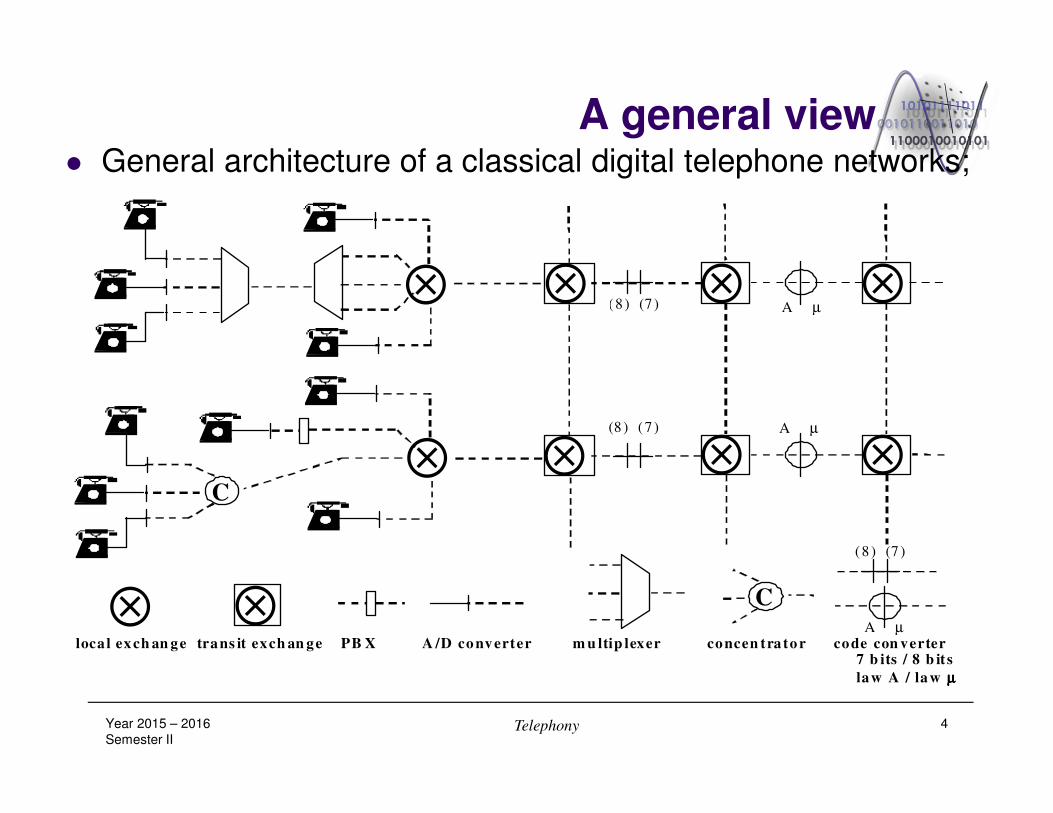
A general view� General architecture of a classical digital telephone networks;
Year 2015 – 2016
Semester IITelephony 4
⊗
⊗C
⊗
⊗ ⊗
⊗ ⊗
⊗(8 ) (7 )
(8 ) (7 )
A µ
A µ
⊗ ⊗loca l ex ch an ge trans it exch an ge PB X A /D co nv erter m u ltip lexer concen tra to r code con verter 7 b its / 8 b it s
law A / la w µµµµ
C A µ
(8 ) (7 )

A general view� The elements of a classical telephone network:
� subscriber terminal:
� performs the conversion of the voice in analog or digital signal;
� ensures the connection to the access network;
� the analogue or digital access network:
� allows the access in the network;
� ensures the remote power supply and the signaling with the subscriber;
� could ensure the multiplexing in some situations;
� the local and the transit analogue or digital switching:
� ensures connectivity between any two or more subscribers;
� the analogue or digital transport network between the local or
transit switching points;
� ensures the transmission of the data streams between switching points and
the multiplexing of these data streams on wide bandwidth channels;
Year 2015 – 2016
Semester IITelephony 5

Basic aspects concerning the switching
� The basic architecture of a telephone exchange;
Year 2015 – 2016
Semester IITelephony 6
Switching Maintenance - Billing
Access Interfaces
Processors
Messaging Bus
Maintenance Module. In-Out Controllers
Line
controllers Trunk
controllers Digital line
controllers
Central
processor
central
Switching
matrix
Processors for special applications
Basic aspects concerning the switching
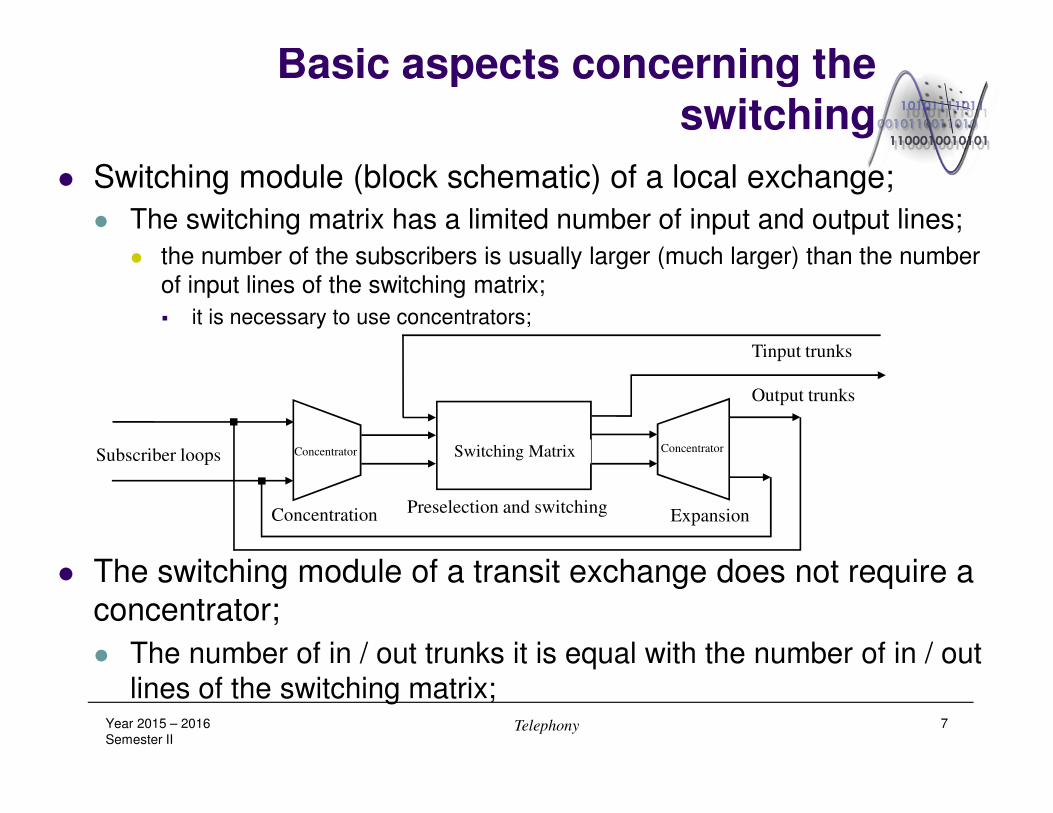
� Switching module (block schematic) of a local exchange;
� The switching matrix has a limited number of input and output lines;
� the number of the subscribers is usually larger (much larger) than the number
of input lines of the switching matrix;
� it is necessary to use concentrators;
� The switching module of a transit exchange does not require a
concentrator;
� The number of in / out trunks it is equal with the number of in / out
lines of the switching matrix;Year 2015 – 2016
Semester IITelephony 7
Concentration ExpansionPreselection and switching
Subscriber loops
Output trunks
Tinput trunks
Switching Matrix ConcentratorConcentrator

Basic aspects concerning the switching
� Typical call structure:
� Detection of the service request;
� Dialing connection;
� Routing through the network;
� Ringing connection and answer detection;
� Talking connection;
� Billing procedure (if necessary);
� Call disconnect;
Year 2015 – 2016
Semester IITelephony 8
Basic aspects concerning the switching
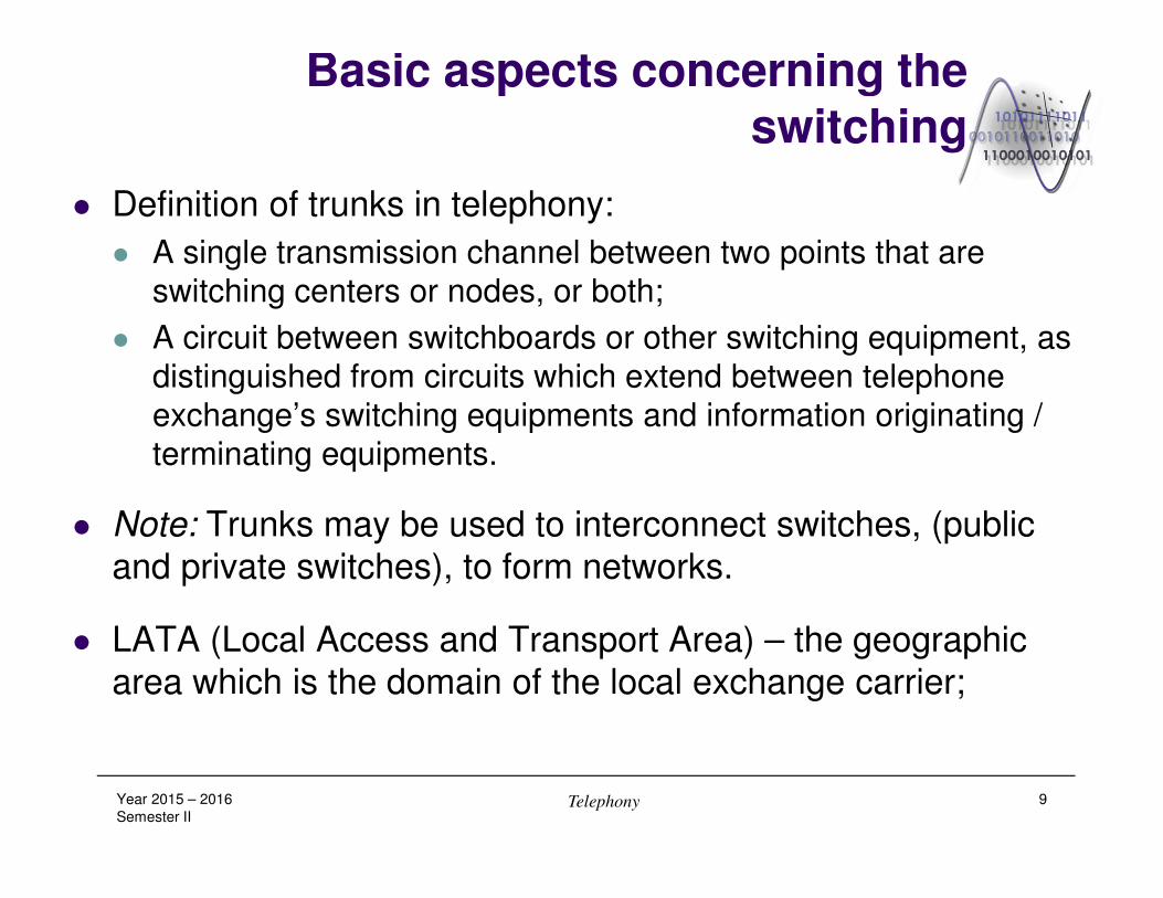
� Definition of trunks in telephony:
� A single transmission channel between two points that are
switching centers or nodes, or both;
� A circuit between switchboards or other switching equipment, as
distinguished from circuits which extend between telephone
exchange’s switching equipments and information originating /
terminating equipments.
� Note: Trunks may be used to interconnect switches, (public
and private switches), to form networks.
� LATA (Local Access and Transport Area) – the geographic
area which is the domain of the local exchange carrier;
Year 2015 – 2016
Semester IITelephony 9
Basic aspects concerning the switching
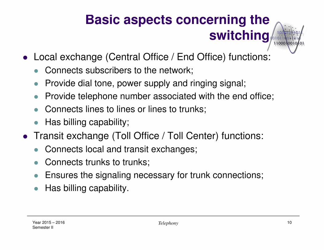
� Local exchange (Central Office / End Office) functions:
� Connects subscribers to the network;
� Provide dial tone, power supply and ringing signal;
� Provide telephone number associated with the end office;
� Connects lines to lines or lines to trunks;
� Has billing capability;
� Transit exchange (Toll Office / Toll Center) functions:
� Connects local and transit exchanges;
� Connects trunks to trunks;
� Ensures the signaling necessary for trunk connections;
� Has billing capability.
Year 2015 – 2016
Semester IITelephony 10
Basic aspects concerning the switching
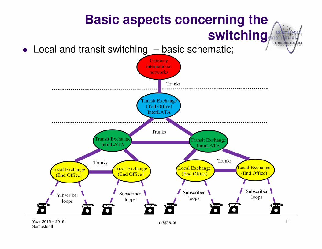
� Local and transit switching – basic schematic;
Year 2015 – 2016
Semester IITelefonie 11
Gateway
international
networks
Transit Exchange
(Toll Office)
InterLATA
Transit Exchange
IntraLATA Transit Exchange
IntraLATA
Local Exchange
(End Office)
Local Exchange
(End Office)
Local Exchange
(End Office)
Local Exchange
(End Office)
Trunks
Subscriber
loops
Trunks
Trunks
Subscriber
loops Subscriber
loops Subscriber
loops
Trunks
Telephone IDN networks
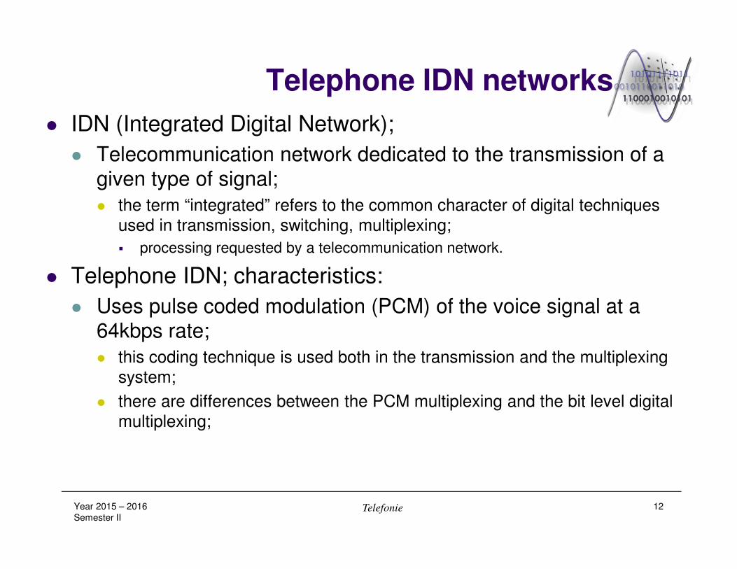
� IDN (Integrated Digital Network);
� Telecommunication network dedicated to the transmission of a
given type of signal;
� the term “integrated” refers to the common character of digital techniques
used in transmission, switching, multiplexing;
� processing requested by a telecommunication network.
� Telephone IDN; characteristics:
� Uses pulse coded modulation (PCM) of the voice signal at a
64kbps rate;
� this coding technique is used both in the transmission and the multiplexing
system;
� there are differences between the PCM multiplexing and the bit level digital
multiplexing;
Year 2015 – 2016
Semester IITelefonie 12

Telephone IDN networks
� Typical multiplexing and transmission system used in a digital
telephone network;
Year 2015 – 2016
Semester IITelephony 13
PCM
MUX
PCM
MUX
PCM
SWITCH
DIGI-
TAL
MUX
DIGI-
TAL
MUX
DIGI-
TAL
MUX
DIGI-
TAL
MUX
PCM
MUX
PCM
MUX
PCM
SWITCH
LT LT LT LT
64kbps 2Mbps 8Mbps 34Mbps 34Mbps 8Mbps 8Mbps 2Mbps 64kbps
Digital line
(cable)
Digital radio link
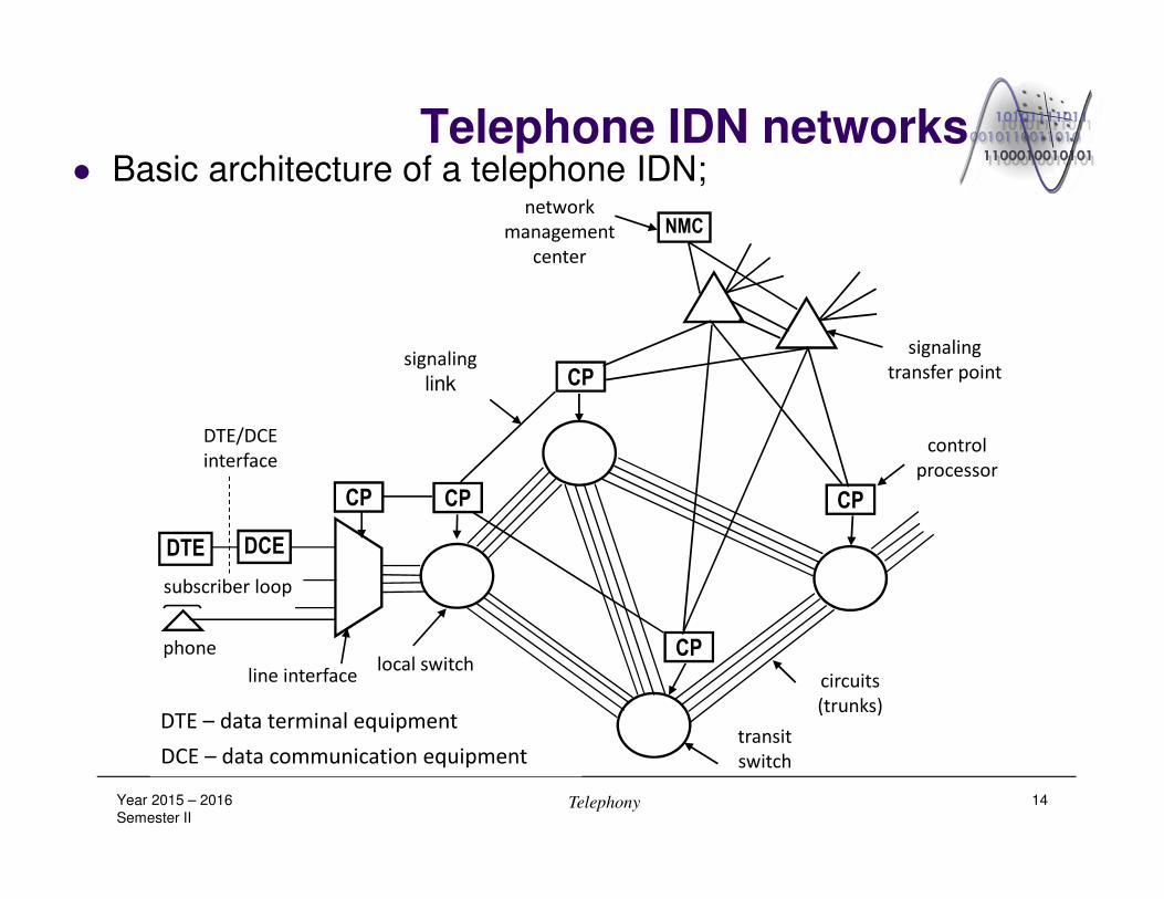
Telephone IDN networks� Basic architecture of a telephone IDN;
Year 2015 – 2016
Semester IITelephony 14
network
management
center
DTE DCE
CP CP
CP
CP
CP
NMC
phone
subscriber loop
local switchline interface
DTE/DCE
interface
signaling
link
transit
switch
control
processor
signaling
transfer point
circuits
(trunks)
DCE – data communication equipment
DTE – data terminal equipment
Telephone IDN networks� Main characteristics of the telephone IDN:
� Circuit switching;
� it ensures input-output connection at 64kbps bit rate;
� the circuit switching (using standardized bandwidths) solves the problem of
resource allocation in extended (global) networks;
� it operates with multiplexed signals having bit rates bigger or equal with the
primary rates – 2048kbps (E1), 1544kbps (T1);
� The local switches are composed of the subscriber stages
(interfacing and concentration role) and group stages (distribution
role); the transit switches are composed of group stages;
� The trunk circuits are provided at 64kbps;
� The PCM multiplex and switching equipments work synchronously
with a common reference frequency of the network;
� it is necessary to implement o proper distribution of the clock according to the
synchronization strategy of the network.
Year 2015 – 2016
Semester IITelephony 15
Telephone IDN networks
� The exchanges are controlled by software programs stored in
reliable processing units;
� The call control information (the signaling) is exchanged between
the switching centers through a dedicated signaling network
using a common channel (CCS – Common Channel Signaling);
� the CCS network is a communication network between computers and uses
packet switching technique to transfer the signaling messages between the
control computers of the exchanges;
� the CCS switch are referred as signaling transfer points (STP – Signaling
Transfer Points);
� the packet switching used in the CCS network is based on datagrams (DG);
� DG is a message that contains in his header the addresses of the transmitter and
receiver exchange and can be routed through the network as an independent
message;
� the datagrams corresponding to a given signaling transaction are routed through
the same path in the CCS network.
Year 2015 – 2016
Semester IITelephony 16
Data IDN networks
� Data applications can be classified according to the terminal
activity during a call:
� the time interval in which the data terminal is active during the
data transfer phase;
� there are two type of data:
� volume data (ex. facsimile, teletex, file transfer) - are characterized by a
intense activity of the terminal;
� and burst data (ex. start-stop transmissions between the data terminal and
the computer, telemetry) - present a low activity of the terminal during the call.
� The IDNs for data communications use circuit switching or
packet switching;
Year 2015 – 2016
Semester IITelephony 17
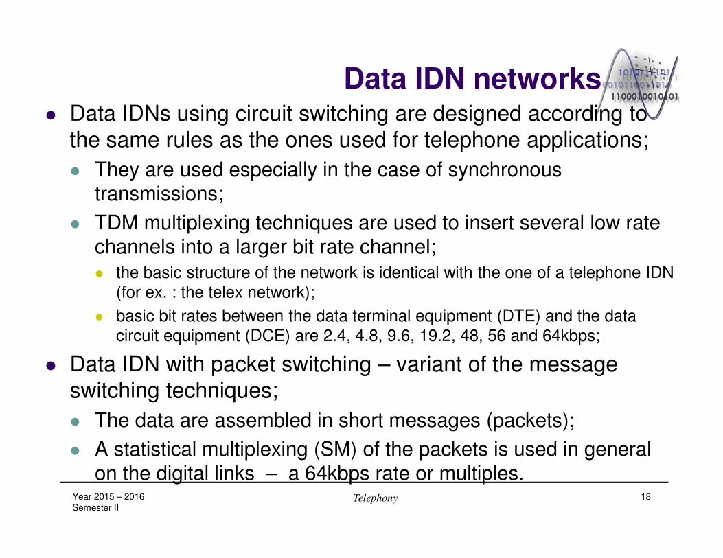
Data IDN networks� Data IDNs using circuit switching are designed according to
the same rules as the ones used for telephone applications;
� They are used especially in the case of synchronous
transmissions;
� TDM multiplexing techniques are used to insert several low rate
channels into a larger bit rate channel;
� the basic structure of the network is identical with the one of a telephone IDN
(for ex. : the telex network);
� basic bit rates between the data terminal equipment (DTE) and the data
circuit equipment (DCE) are 2.4, 4.8, 9.6, 19.2, 48, 56 and 64kbps;
� Data IDN with packet switching – variant of the message
switching techniques;
� The data are assembled in short messages (packets);
� A statistical multiplexing (SM) of the packets is used in general
on the digital links – a 64kbps rate or multiples.Year 2015 – 2016
Semester IITelephony 18
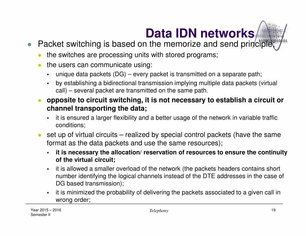
Data IDN networks� Packet switching is based on the memorize and send principle;
� the switches are processing units with stored programs;
� the users can communicate using:
� unique data packets (DG) – every packet is transmitted on a separate path;
� by establishing a bidirectional transmission implying multiple data packets (virtual
call) – several packet are transmitted on the same path.
� opposite to circuit switching, it is not necessary to establish a circuit or
channel transporting the data;
� it is ensured a larger flexibility and a better usage of the network in variable traffic
conditions;
� set up of virtual circuits – realized by special control packets (have the same
format as the data packets and use the same resources);
� it is necessary the allocation/ reservation of resources to ensure the continuity
of the virtual circuit;
� it is allowed a smaller overload of the network (the packets headers contains short
number identifying the logical channels instead of the DTE addresses in the case of
DG based transmission);
� it is minimized the probability of delivering the packets associated to a given call in
wrong order;
Year 2015 – 2016
Semester IITelephony 19
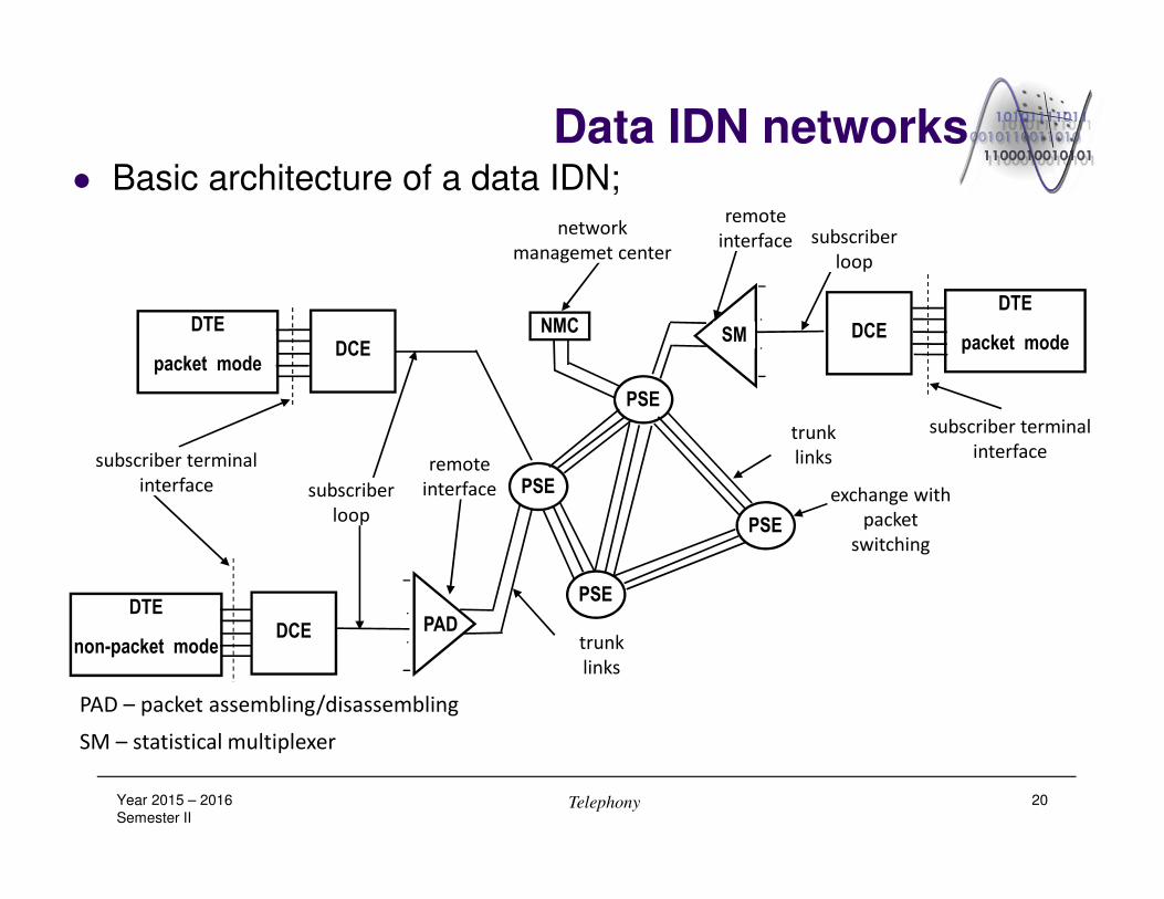
Data IDN networks� Basic architecture of a data IDN;
Year 2015 – 2016
Semester IITelephony 20
DTE
non-packet mode
DTE
packet modeDCE
DCE
DTE
packet mode
PAD
SM
-
.
.
-
-
.
.
-
PSE
PSE
PSE
PSE
NMC
subscriber terminal
interface subscriber
loop
remote
interface
remote
interface
trunk
links
trunk
links
subscriber
loop
subscriber terminal
interface
exchange with
packet
switching
network
managemet center
DCE
PAD – packet assembling/disassembling
SM – statistical multiplexer

ISDN networks
� ISDN (Integrated Services Digital Network) – digital network
with integrated services;
� Requested by the apparition of new communication services;
� An ISDN network is characterized by three main aspects:
� 1. End-to-end digital connectivity;
� 2. Multi-service capacity (voice, data, video);
� 3. Standard interfaces;
� it is ensured a multitude of digital communication modes, unitary
administration and a limited set of standard user interfaces.
� Usually an ISDN network is based on the telephone IDN with
64kbps bit rate channels, including the digital subscriber line
equipments;
Year 2015 – 2016
Semester IITelephony 21
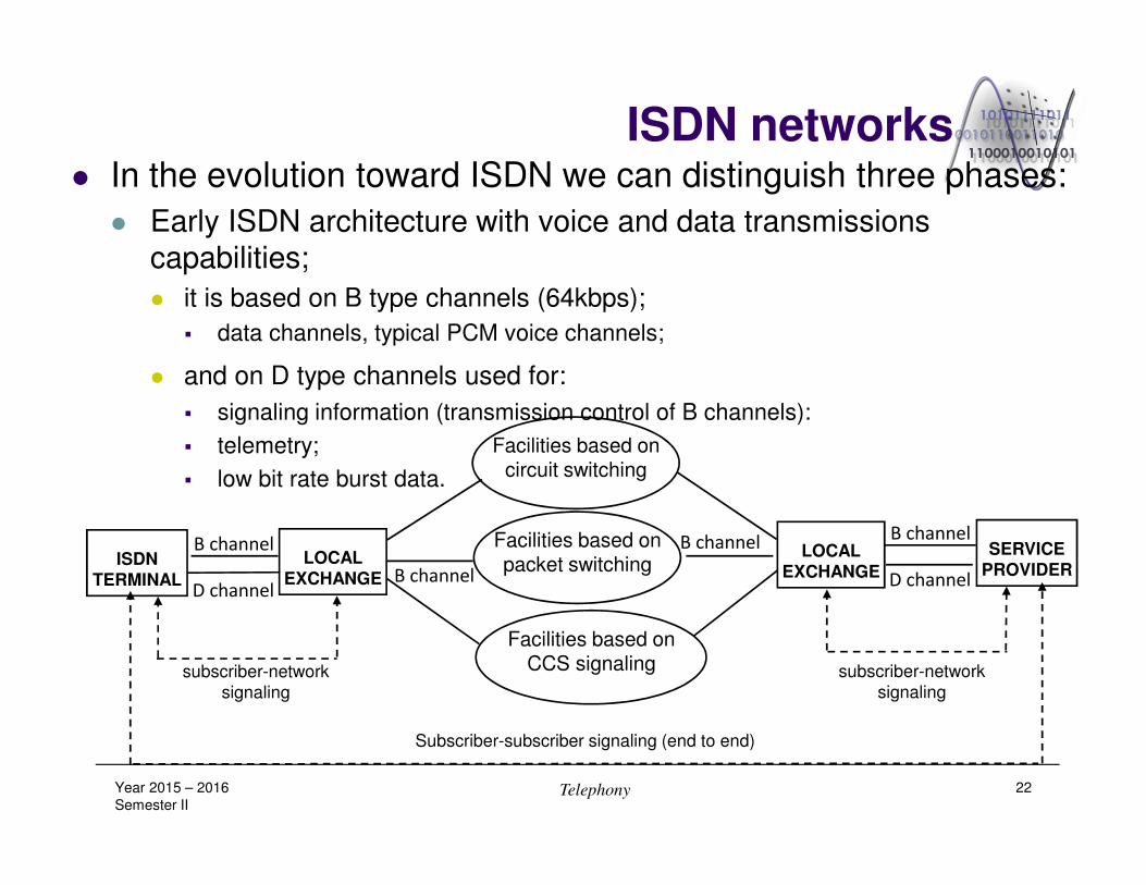
ISDN networks� In the evolution toward ISDN we can distinguish three phases:
� Early ISDN architecture with voice and data transmissions
capabilities;
� it is based on B type channels (64kbps);
� data channels, typical PCM voice channels;
� and on D type channels used for:
� signaling information (transmission control of B channels):
� telemetry;
� low bit rate burst data.
Year 2015 – 2016
Semester IITelephony 22
ISDNTERMINAL
LOCALEXCHANGE
SERVICEPROVIDER
LOCALEXCHANGE
B channel
D channel
B channel
D channelB channel
B channelFacilities based on packet switching
Facilities based on CCS signaling
Facilities based on circuit switching
subscriber-network
signaling
subscriber-network
signaling
Subscriber-subscriber signaling (end to end)
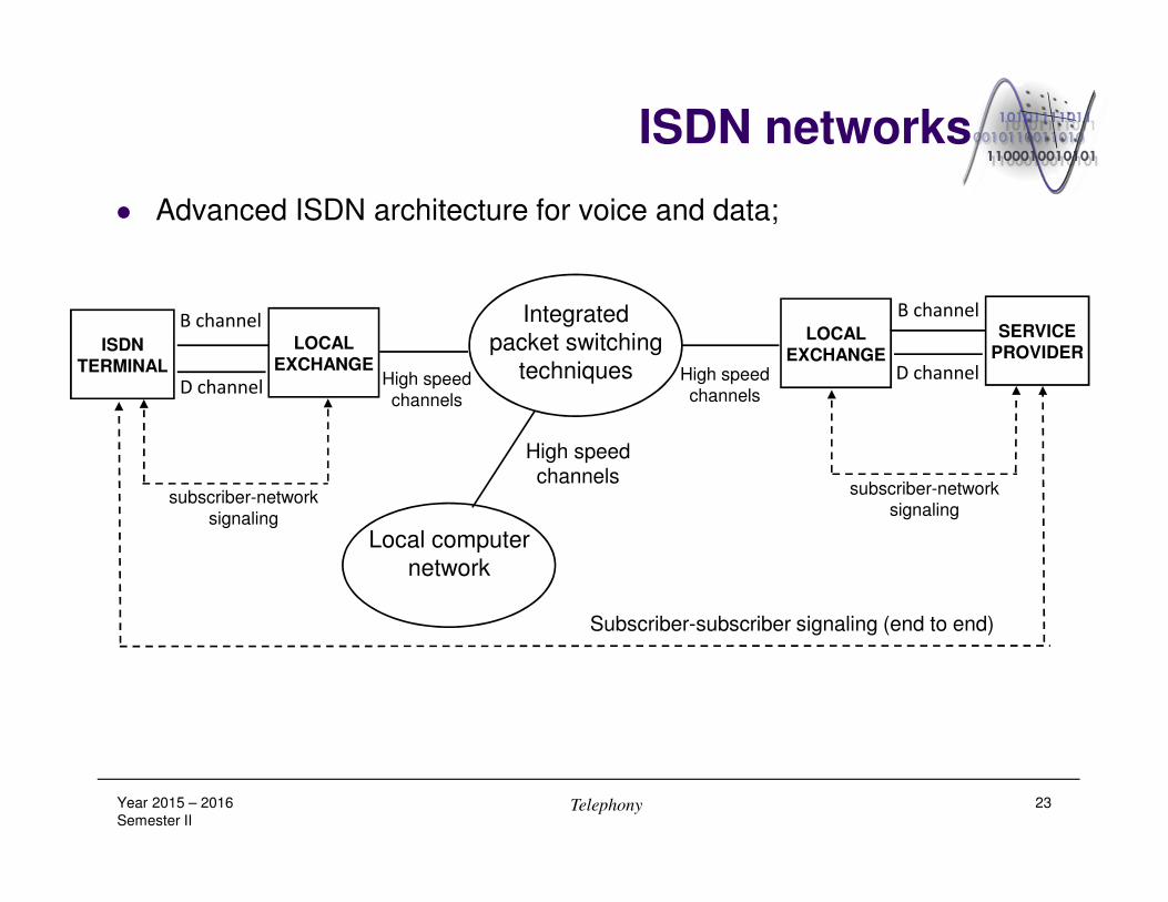
ISDN networks
� Advanced ISDN architecture for voice and data;
Year 2015 – 2016
Semester IITelephony 23
ISDNTERMINAL
LOCALEXCHANGE
SERVICEPROVIDER
LOCALEXCHANGE
D channel
B channel
D channelHigh speed
channels
subscriber-network
signaling
subscriber-network
signaling
High speed
channels
B channel Integrated
packet switching
techniques
Local computer
network
High speed channels
Subscriber-subscriber signaling (end to end)

ISDN networks
� ISDN architecture with wide band capability;
Year 2015 – 2016
Semester IITelephony 24
Facilities based on packet switching
Facilities based on circuit switching
Facilities based on wide band packet
switching
Video service provider
RSU
NBS
WBS
analogue loop
digital loop
optic fiber digital loop
optic fiber connection
localexchange
remote switching unit
voice
voice
data
voice
data
video
RSU – remote switching unit
NBS – narrow band switching system
WBS – wide band switching system

ISDN networks� Basic architecture of a narrow band ISDN exchange;
Year 2015 – 2016
Semester IITelephony 25
Digital
switching
network
Stored program control module
Trunk handling stage
(Inter-exchange
signaling interface)
NT ISDN line circuit
Analogue line
circuit A/D
ISDN workstation
Subscriber
access unit
Internal digital
communication interface
Internal digital
signaling interface
Digital switching exchange
Main distribution frame
Digital distribution frame
ISDN phone
Computer Network
terminator 1
S/T U
ISDN service access point
ISDN line
2B+D channels
Digital multiplex trunk
Digital multiplex trunk
Multiplex trunk interfaces
To/from other
exchange
Analogue line Analogue
phone
ISDN line
interface
Analogue line
interface
Analogue service access point
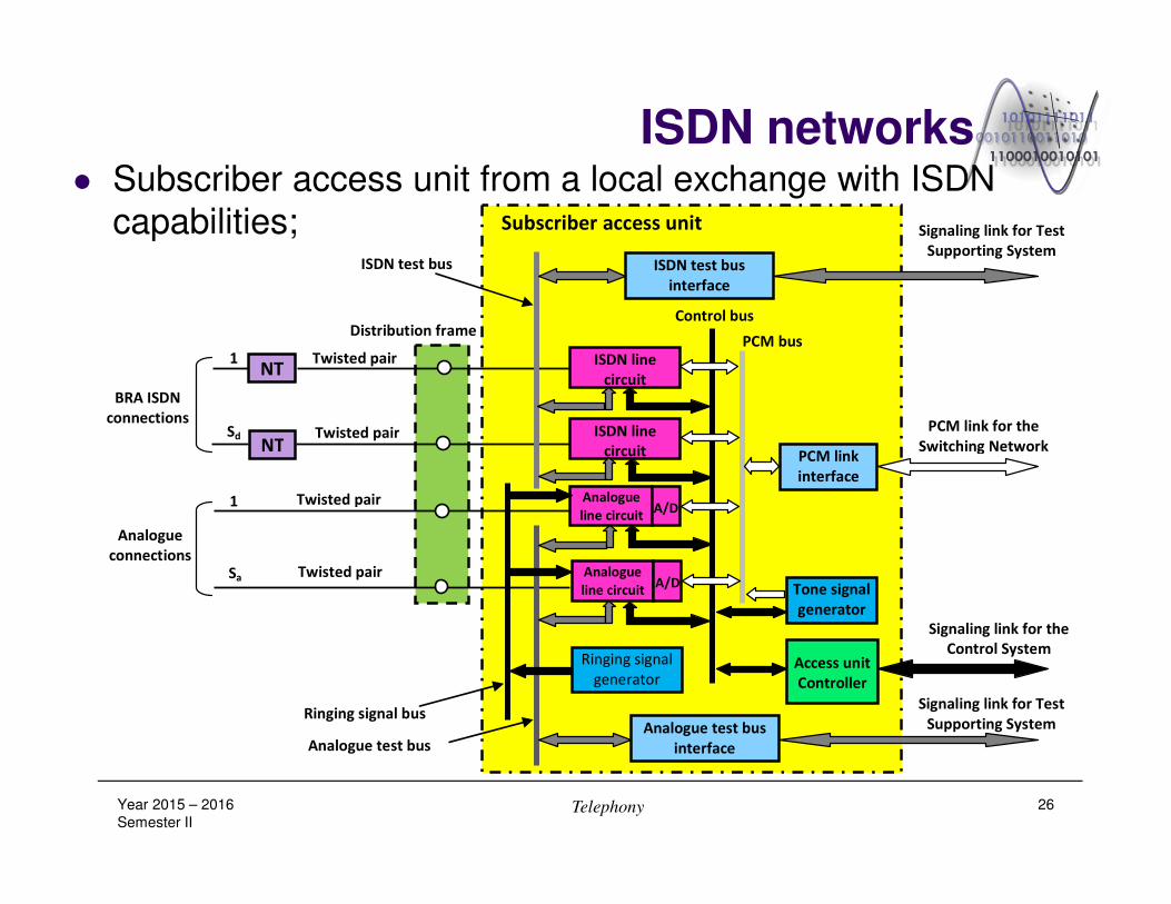
ISDN networks� Subscriber access unit from a local exchange with ISDN
capabilities;
Year 2015 – 2016
Semester IITelephony 26
BRA ISDN
connections
Analogue
connections
NT
NT
ISDN line
circuit
ISDN line
circuit
Analogue
line circuit A/D
Analogue
line circuit A/D
ISDN test bus
interface
PCM link
interface
Tone signal
generator
Analogue test bus
interface
Ringing signal
generator Access unit
Controller
Twisted pair
Twisted pair
Twisted pair
Twisted pair
1
1
Sd
Sa
Distribution frame
Subscriber access unit
ISDN test bus
Analogue test bus
Ringing signal bus
PCM bus
Control bus
Signaling link for Test
Supporting System
PCM link for the
Switching Network
Signaling link for Test
Supporting System
Signaling link for the
Control System

Usual definitions in classical telephony
� 1. Transmission channel (path);
� The combination of means necessary to ensure the transmission
of signals in one direction between two points;
� several channels can be multiplexed on a common transmission medium by
frequency or time division multiplexing;
� a digital channel is provided at 64kbps rate on a digital link;
� 2. Circuit section;
� Includes two digital channels, one for every transmission direction;
� It is defined by two consecutive points in which time conversions are
performed;
� 3. Circuit;
� The combination of two channels that ensures a bidirectional
transmission between two points;
� Note: in telephony the term „circuit” is synonymous with „telecommunication
circuit” which connects two switching centers;Year 2015 – 2016
Semester IITelephony 27
Usual definitions in classical telephony
� 4. Digital link (Digital path);
� The combination of means that allow to transmit and receive a
digital signal with specified bit rate between two digital distribution
frames (or equivalent equipments);
� Note: a digital link includes one or more digital sections;
� 5. Digital section;
� The combination of means that allow the transmission and the
reception of digital signals with specified bit rates between two
consecutive digital distribution frames (or equivalent equipments).
� 6. Digital line section;
� Consists of two consecutive line terminating equipments, the
transmission medium that connects them and the internal cabling
of the exchange located between them and the distribution frames
(or their equivalent);Year 2015 – 2016
Semester IITelephony 28

Usual definitions in classical telephony
� 7. Digital line path (Digital line link);
� It is formed by two or more digital line sections connected so that
the specified bit rate is the same on the entire path between two
terminal digital distribution frames (or their equivalent);
� 8. Digital block:
� The combination formed by a digital link and the associated
multiplexing equipments;
� 9. Primary block:
� Is the basic PCM group, assembled by time domain multiplexing;
� Primary block „µ” – basic PCM group formed from 24 basic 64kbps channels
having a 1544kbps rate;
� Primary block „A” – basic PCM group formed from 32 basic 64kbps channels
having a 2048kbps rate;
Year 2015 – 2016
Semester IITelephony 29
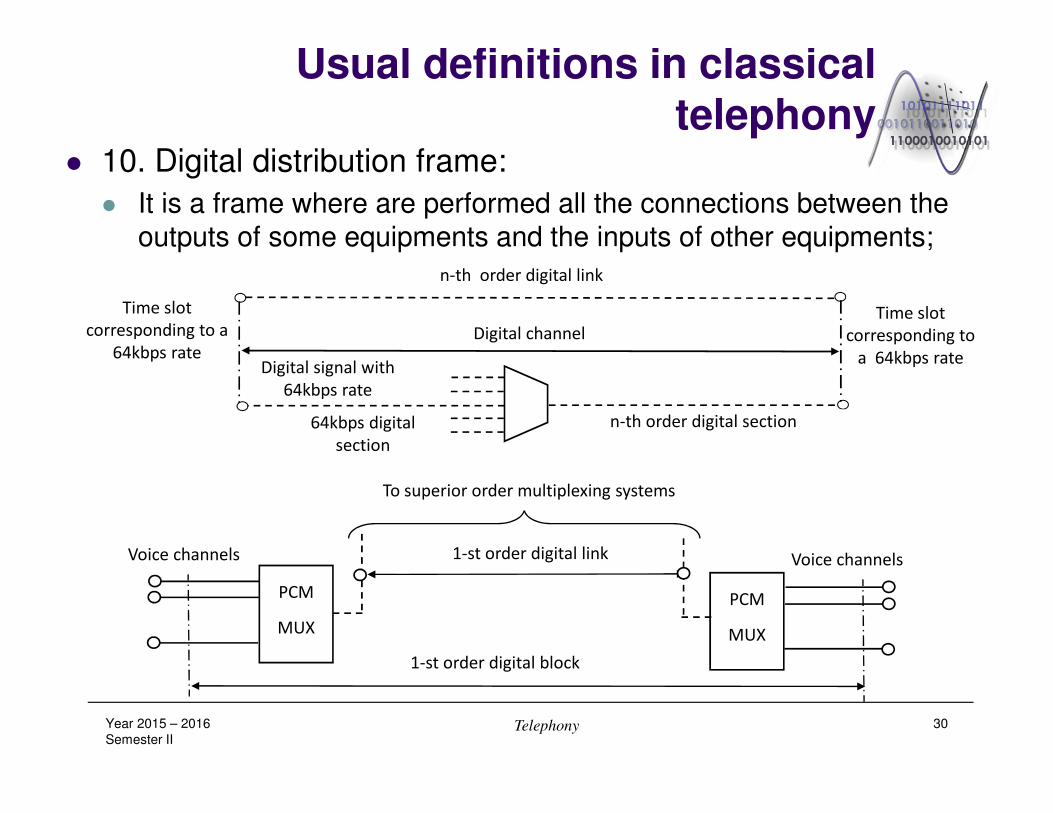
Usual definitions in classical telephony
� 10. Digital distribution frame:
� It is a frame where are performed all the connections between the
outputs of some equipments and the inputs of other equipments;
Year 2015 – 2016
Semester IITelephony 30
Time slot
corresponding to a
64kbps rate
Time slot
corresponding to
a 64kbps rate
n-th order digital link
Digital channel
Digital signal with
64kbps rate
64kbps digital
section
n-th order digital section
PCM
MUX
PCM
MUX
Voice channels Voice channels
1-st order digital block
1-st order digital link
To superior order multiplexing systems

Usual definitions in classical telephony
Year 2015 – 2016
Semester IITelephony 31
64kbps transmission system
(ex. twisted pairs)
Echipamen de
transmisie
64kbps transmission system (ex. twisted pairs)
1-st order transmission system (ex. twisted pairs)
(de ex. perechi de fire torsate)
n-th order transmission system
(ex. ex.) optic fiber radio relay)
Digital section
64 kbps Digital section at de 64 kbps
Digital link at 64 kbps
Digital section
64 kbps
Line digital section at 64 kbps
Line digital section at 64 kbps
1-st order Digital bloc
2-nd order Digital block
n-th order Digital block
n-th order Line
digital section
n-th order Line
digital section 1-st order Line digital section
1-st order Line digital section
1-st order Digital section
1-st order Digital section 1-st order Digital section
1-st order Digital link
2-nd order Digital section
n-th order Digital link
64 kbps
level
1-st order
2-nd order
n-th order
transmission
systems
Transmission equipment
Digital distribution
frame
Multiplexing/ Demultiplexing equipment