course on design of steel structures professor …...gusset plate. design the welded connection to...
TRANSCRIPT

Course on Design of Steel StructuresProfessor Damodar Maity
Department of Civil EngineeringIndian Institute of Technology Kharagpur
Lecture 10Module 2
Design of Fillet welds
Hello, today I am going to discuss about design of Fillet welds. In last lecture I have
discussed about the fillet welds, means different parameters used for fillet welds like what is
the effective length of the weld, what is the total length of the weld, what is the size of the
welds, what is the effective thickness of the weld etc. We have also discussed to find out the
maximum allowable throat thickness of the size and minimum size of the weld on the basis of
the plate thickness and finally we have discussed about the design strength of fillet weld,
right.
(Refer Slide Time: 1:10)
This is the same formula to calculate the design strength of the fillet weld,
u w edw
mw
f L tP =
3γ

Lw = length of weld in mm
fu = ultimate stress of weld in MPa
te = effective throat thickness = 0.7S
γmw = partial safety factor
= 1.25 for shop welding and
= 1.5 for site welding
S = size of weld in mm
We generally use right angle and for that it is 0.707S and on the basis of this, we will go
through one workout example. If some load is given then how to find out the length of the
weld and how to distribute the length of the weld in different site that will see through this
workout example.
(Refer Slide Time: 2:04)
Example:A tie member of a roof truss consists of ISA 100×75×8 of Fe410 grade, is welded to a 10 mmgusset plate. Design the welded connection to transmit a tensile load, T. Assume connectionare made in the workshop.
So here the thickness is given means thickness of the gusset plate is given 10 mm and
thickness of the angle is 8 mm, so from these two we can find out the size of the weld right.
So this is one thing second thing is that this is an angle section so its cg distance will not be at
the middle not at will be at the centre. So that means the weld length will not be distributed
equally in upper side and lower side so, the design of weld has to be made in such a way the
equivalent strength passes through the cg.
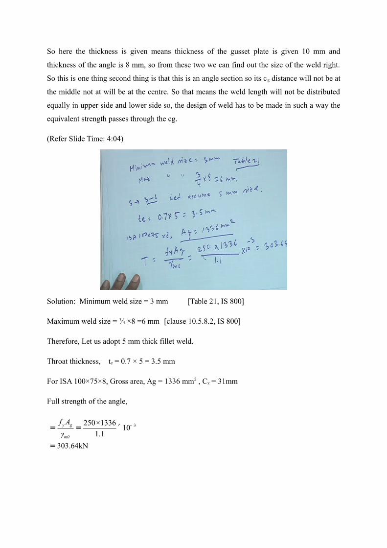
(Refer Slide Time: 4:04)
Solution: Minimum weld size = 3 mm [Table 21, IS 800]
Maximum weld size = ¾ ×8 =6 mm [clause 10.5.8.2, IS 800]
Therefore, Let us adopt 5 mm thick fillet weld.
Throat thickness, te = 0.7 × 5 = 3.5 mm
For ISA 100×75×8, Gross area, Ag = 1336 mm2 , Cz = 31mm
Full strength of the angle,
3250×133610
1.1
303.64kN
y g
m0
f A
γ-= = ´
=

Strength of 5-mm weld,
3.5 410662.8 /
3 1.25
N mm
Force to resist by weld at 100 mm side of angle,
32 662.8 100 10 66.28 P kN
Force to resist by weld at upper side of angle,
21
303.64 31 66.2861
2 100 2
PTyP kN
d
Force to resist by weld at lower side of angle,
3
1
61 1092
662.8
wL mm
Length required at upper side of angle
3
3
176.36 10266
662.8
wL mm
Total Length (effective) of weld = 266 + 92+100 = 458 mm
Note: Add twice the weld size at the ends.
Thus total length = 458+2S = 468 mm

(Refer Slide Time: 8:07)
(Refer Slide Time: 12:21)

(Refer Slide Time: 13:22)
(Refer Slide Time: 16:07)
So whatever you are getting you have to represent in terms of drawing so that engineer can
understand at the site. Here one thing we have to remember, we provide the effective length
suppose length whatever we are providing is effective length and engineer has to add to this

that means the size of the weld it has to add and then it has to fabricate right. So this is one
example.
(Refer Slide Time: 18:26)
Example Design a suitable fillet weld to connect web plate to flange plate and flange plate toflange cover plate of a built-up girder as shown in the figure, for the following data. Assumeshop welding.
Web plate: 1200 mm × 12 mm
Flange plate: 450 mm × 20 mm
Flange cover plate: 350 mm × 16 mm
Maximum Factored shear force: 1600 kN
(Refer Slide Time: 19:25)

(Refer Slide Time: 20:32)

For Fe 410 steel:
410uf MPa
For shop weld:
1.25mw
Permissible shear stress
2410189.37 /
3 3 1.25
u
mw
fN mm
Connection of web plate to flange plate:
Size of weld: Minimum = 5 mm [Table 21, IS 800]
Maximum = 12 – 1.5 =10.5 mm [clause 10.5.8.1, IS 800]
Let us provide 7 mm size of fillet weld.
Effective throat thickness of weld
0.7 7 4.9 et KS mm
2 4.9 9.8 et mm
450 20 (600 10) 350 16 (600 20 8) Ay
4 3900.68 10 mm

3 3 32 2350 16 450 20 12 1200
2 [ 350 16 628 450 20 610 ]12 12 12
zzI
9 412.8 10 mm
Shear stress:
3 42 2
9
1600 10 (900.68 10 )114.9 / 189.37 /
12.8 10 9.8
zz e
VAyN mm N mm
I t
Hence, the weld is safe.

(Refer Slide Time: 27:30)
Connection of flange plate to flange cover plate:
Adopt a 7 mm fillet weld.
0.7 7 4.9 et KS mm
2 4.9 9.8 et mm
4 3350 16 (600 20 8) 351.68 10 Ay mm
(Refer Slide Time: 29:18)

Shear stress:
3 42 2
9
1600 10 (351.68 10 )44.86 / 189.37 /
12.8 10 9.8
zz e
VAyN mm N mm
I t
Hence, the weld is safe.
(Refer Slide Time: 30:57)
This is how we can check the joint whether it is ok or not right. So in todays lecture what we
have seen that two type of problem we have come across and we have seen how to calculate
the design strength of the weld or how to design the weld joint. And in first case we have seen
how the distribution of the weld will be done for an angle section because in angle section cg
distance is not at the centre so we have to make the weld connection in such a way that
strength of the weld connection coincide with the cg of the joint. So this is what we have
done, this is all for todays lecture, thank you.