cover - single sided - keith fowler agencies · designed with improved point and flute geometries...
TRANSCRIPT

S O M T A U S E R G U I D E

SOMTA TECHNICAL SERVICES
FULL SPECIFICATIONS IN SOMTA CATALOGUES
PRODUCT RANGE STANDARDS & SPECIALS
TechnicalAssistance
This handbook is intended to help you get maximum performance fromSOMTA cutting tools. Whilst the information covers most common uses andproblems it is not possible to deal with every situation. Our trained salesrepresentatives are available to further assist and advise, fully backed up byfactory technical services.
SOMTA TOOLS (PTY) LTD is a world class manufacturer producing precision
cutting tools to international standards and specifications which include British Standard, DIN, ISO, ANSI and JIS. Full details of specifications arelisted in our catalogues which are available from leading Industrial Distributors or directly from the Somta factory.
The SOMTA range consists of over 7 000 standard items and we have a cutting tool available for almost every application. Sometimes a specialtool is needed and our product engineers at the SOMTA factory can designa special purpose tool to do the job. These can also be manufactured tocustomers’ specifications or to a sample.

IntroductionManufacturers & Suppliers of Drills, Reamers, End Mills,
Bore Cutters, Taps & Dies, Toolbits, Solid Carbide Tooling,
Carbide Insert Tooling, Custom Tools and Surface Coatings
Profile
SOMTA TOOLS vision as a world class provider of cutting tools, is supported
by ISO 9001 accreditation.
SOMTA TOOLS specialises in the design and manufacture of drills, reamers,
milling cutters, toolbits, threading tools and custom tools for the industrialand “DIY” markets, offering the innovative range of Balzers BALINIT highperformance coatings on all cutting tools.
®
The CompanySOMTA TOOLS factory in Pietermaritzburg manufactures over 7 000 standard
items and a further 3 000 made-to-order items to serve the domestic and export markets in over 70 countries worldwide.
The ProductSOMTA TOOLS standard catalogue range of
precision cutting tools are supplied through aextensive network of industrial distributors,backed up by technical sales representativeswho are available to provide technical assistance where required.
Should a special production applicationrequiring specially designed customtooling be requested, Somta is able to provide a full technical design service.

Manufacturers of precision industrial andDIY coated cutting toolsStandard and custom designed tooling
The major functions the end user,
apprentice or student can expect from
Somta’s technical representatives and
design departments are as follows:
• Provision of technical literature to assist
with the correct application of Somta’s
tooling.
• Assistance with and solution of any tooling
design and application relating to Somta’s
custom tooling.
• Advice, suggestions and
recommendations on product
improvement or innovation. Provision of
training in the use, care and
resharpening of high speed steel cutting
tool on request.
• Liaison between the customer and
Somta’s factory estimator and production
staff, to deliver the required tooling on
time according to specification, to the
customers complete satisfaction.
Contact our technical department on
for technical assistance if experiencing
a cutting tool problem.
Tel: +27 33 355 6600 or
e-mail: [email protected]
AN EXAMPLE OF BEFORE
AND AFTER REGRINDING
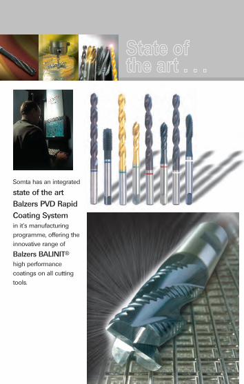
State ofthe art . . .
Somta has an integrated
state of the art
Balzers PVD Rapid
Coating Systemin it’s manufacturing
programme, offering the
innovative range of
®Balzers BALINIT
high performance
coatings on all cutting
tools.
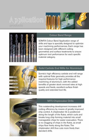
Applicationproducts
SOMTA Colour Band Application range of drills and taps is specially designed to optimize your machining performances. Each range has been designed with different cutting geometries and surface treatments to ensure optimum tool performance for each specific material category.
This outstanding development increases drill cutting efficiency by means of greatly improved chip control. A chipbreaker rib is positioned along the length of the flutes, which curls and breaks long chip forming material into small manageable chips for easier evacuation. There is no clogging of chips in the flutes, as small chips flow freely along the flutes. The chipbreaker drill thus cuts more freely than standard drills.
MTS Chipbreaker Drills
Colour Band Range
Solid Carbide End Mills for Aluminium
Somta's high efficiency carbide end mill range with optimal flute geometry provides all the required features for high performance machining of aluminium, with the added benefits of greater stock removal rates at high speeds and feeds, excellent surface finish quality and extended tool life.

Reamer Tool Range
Established in 1954, Somta offers a range of high quality standard reamer products and custom reaming solutions. From closest tolerance precision machining of extremely accurate holes through to enlargement, alignment and deburring of holes for construction, assembly and general purpose applications. We have a product or a solution to satisfy your specific engineering requirements.
Application
UD Ultra Parabolic Twist Drills
A comprehensive range of heavy duty drills designed with improved point and flute geometries for enhanced penetration and chip removal in long chip forming, short chip forming and abrasive material groups. This range of Parabolic Flute Ultra Drills are designed to meet the challenges of a broad spectrum of difficult drilling applications.
products
Somta's Solid Carbide Tooling Range is a comprehensive family of solid carbide stub and jobber length drills, 2 and 4 flute end mills and ball nose end mills, in both regular and long series, and almost any special form carbide tooling.
Solid Carbide Tooling (Standard Range)

Applicationproducts
Solid Carbide VariCut End Mills
Somta's new "Vari-Style" End Mill, VariCut has a new patent pending tool design. This unique design uses a new core form and a new reinforced end geometry with unequal flute spacing which enables it to remove the most amount of material in the least amount of time with an excellent surface finish. On Stainless, or Titanium, it will match or outperform any other 4 flute "Vari-Style" End Mill in the market.
IF YOU CANNOT FIND AN ANSWER TO YOUR PROBLEM INTHIS BOOKLET PLEASE CONTACT THE SOMTA FACTORY
Solid Carbide Hard Material End Mills
A range of high performance finishing end mills for operation on hard materials up to 52HRC (512HB), plus Somta's Hi-Feed end mill with patent pending geometry that removes the most amount of material in the least amount of time combined with extended tool life, for use on hard and super hard steels up to 62HRC (684HB).

Standardproducts
Morse Taper Shank Drills
Reamers, Countersinks& Counterbores
Bore Cutters
Toolbits
Straight Shank Drills
Shank Cutters
Threading Tools
Standardproducts

ContentsCUTTING TOOL MATERIALS
SURFACE TREATMENTS 3-4
DRILLS
- Selecting the correct drill 5-10
- Drill nomenclature 11-12
- Types of spiral (or helix) angles 12
- Drill point styles 13-15
- Flute forms 15
- Common re-sharpening errors 16-17
- Standard morse taper shank 17
- How to order specials 18-20
- Cutting diameter tolerance 21
- Core drilling
- Core drill nomenclature 22-23
- A guide to core drilling 23
- Centre drills
- Centre drill nomenclature 24
- Selecting the correct centre drill 25
- The correct use of centre drills 26
- The correct use of drills 27-28
- Drilling problems: Causes and solutions 29-32
- Drill feed curve chart 32-33
- Drill technical data 34-35
- UD drill technical data 36-37
- Solid carbide drills technical data 38-39
REAMERS, COUNTERSINKS & COUNTERBORES
- Selecting the correct reamer, countersink & counterbore 40-41
- Reamers
- Reamer nomenclature 42
- The correct use of reamers 43-44
1-2
Contents - Re-sharpening reamers 44-45
- Counterbores
- Counterbore nomenclature 45
- The correct use of counterbores 46
- Re-sharpening counterbores 46
- Countersinks
- Countersink nomenclature 47
- The correct use of countersinks 47
- Re-sharpening countersinks 47
- Reaming problems: Causes and solutions 48-49
- Reamer technical data 50-51
TAPS
- Selecting the correct tap 52-58
- Tap nomenclature 59-60
- Standard lead (chamfer angles) 61
- Thread forms 62-67
- Recommended tapping drill sizes 68-74
- Fluteless taps 75
- Correct use of taps 76-80
- Re-sharpening taps 80
- Tapping problems: Causes and solutions 81-87
- Tap technical data 88-91
- CBA tap technical data 92-93
- Tap peripheral speed to rpm conversion chart 94-95
CUTTERS
- Shank cutters
- Selecting the correct shank cutter 96-100
- Shank cutter nomenclature 101-105
- Shank options 106
- Hints for successful shank cutter usage 107
Contents - Arbor mounted cutters
- Selecting the correct arbor mounted cutter 108-110
- Arbor mounted cutter nomenclature 111-114
- Hints for successful arbor mounted cutter usage 115-116
- Slitting saws
- Selecting the correct slitting saw 117
- Slitting saw nomenclature 118
- Hints for successful slitting saw usage 119
- Climb or conventional milling 120-121
- Problem solving 122-123
- Difficult to machine materials 124
- Re-sharpening and care of milling cutters 125
- Solid carbide end mills technical data 126-133
- Cutter technical data 134-137
- Feeds per tooth 138-145
- Speed and feed formula 146
GENERAL INFORMATION
- Tolerances 147
- Peripheral speed to rpm conversion chart 148-149
- Inch-millimeter conversion table 150-151
- Approximate hardness and tensile strength conversions 152
- Hardness conversion chart for high speed steel 153
- Useful formulae 154-158
- Useful tapers 159
- Morse taper and brown and sharpe tapers 160
- Conversion factors 161
- Number and letter drill sizes 162
NOTES 163-166
1WORLD CLASS CUTTING TOOLS
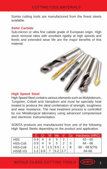
Somta cutting tools are manufactured from the finest steelsavailable.
Solid CarbideSub-micron or ultra fine cabide grade of European origin. Highstock removal rates with excellant rigidity at high speeds andfeeds and extended wear life are the major benefits of thismaterial.
High Speed SteelHigh Speed Steel contains various elements such as Molybdenum,Tungsten, Cobalt and Vanadium and must be specially heattreated to produce the ideal combination of strength, toughnessand wear resistance. The heat treatment process is controlledby our Metallurgical laboratory using advanced computerisedand electronic instrumentation.
SOMTA products are manufactured from one of the followingHigh Speed Steels depending on the product and application.
Hardness (HRC)63 - 6564 - 66
66 - 68.5(70)64-66
C0.90.91.11.2
Cr444
3.9
W66
1.57
Mo55
9.55.2
V221
2.7
Co-58-
HSSHSS-Co5HSS-Co8HSSE-V3
CUTTING TOOL MATERIALS
2 WORLD CLASS CUTTING TOOLS
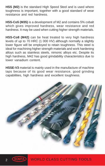
HSS (M2) is the standard High Speed Steel and is used wheretoughness is important, together with a good standard of wearresistance and red hardness.
HSS-Co5 (M35) is a development of M2 and contains 5% cobaltwhich gives improved hardness, wear resistance and redhardness. It may be used when cutting higher strength materials.
HSS-Co8 (M42) can be heat treated to very high hardnesslevels of up to 70 HRC (1 000 HV) although normally a slightlylower figure will be employed to retain toughness. This steel isideal for machining higher strength materials and work hardeningalloys such as stainless steels, nimonic alloys etc. Despite itshigh hardness, M42 has good grindability characteristics due tolower vanadium content.
HSSE-V3 material is mainly used in the manufacture of machinetaps because of its good wear resistance, good grindingcapabilities, high hardness and excellent toughness.
3WORLD CLASS CUTTING TOOLS
Bright FinishA bright finish tool has no surface treatment and is suitable forgeneral purpose use.
Blue FinishA blue finish is achieved by steam tempering - a thermal pro-cess which imparts a non-metallic surface to the tool. Thissurface is porous and by absorbing lubricant, helps preventrusting, reduces friction and cold welding, resulting in increasedtool life. Steam tempered products can successfully be used atslightly increased machining rates or on more difficult to machinematerials.
Gold Oxide FinishThis is a metallic brown coloured surface treatment achievedby a low temperature temper and is normally only used oncobalt products for identification purposes.
NitridingNitriding imparts a hard surface to the tool and is used forprolonging tool life and machining difficult to machine materials.Because nitriding makes the edge more brittle, care must beexercised in the type of application.Nitrided tools are normally also steam tempered.
Titanium Nitride Coating (TiN)TiN coating is a very hard, gold coloured surface coating a fewmicrons thick which is applied by means of a complex process,called Physical Vapour Deposition (PVD), by advanced modernequipment. The coating is non-metallic and therefore reducescold welding.
In certain applications increased speed and feed rates can beachieved because of:
(a) The hardness of the coating.
SURFACE TREATMENTS

4 WORLD CLASS CUTTING TOOLS
(b) The reduction in cutting force required due to a decrease infriction between the tool and the workpiece.
Tool performance will deteriorate after re-sharpening.
TiCN (Titanium Carbonitride)The addition of carbon to TiN results in a significant increase inthe hardness of TiCN over TiN. TiCN also has a much lowercoefficient of friction which enhances the surface finish ofcomponents machined with TiCN coated tools, higher productivitycan be achieved on a wide range of materials but, in particularstainless steel, titanium and nickel based alloys. It is nowgenerally accepted that TiCN coating has been superseded byTiAlN for most machining applications.
TiAlN (Titanium Aluminium Nitride)In addition to a higher hardness than both TiN and TiCN thealuminium in the coating imparts a much greater oxidation stability.This is as a result of a very thin film of (Aluminium Oxide) beingformed on the surface of the TiAlN. The film is self repairing,leading to additional increased service life. These improvementsallow the coating to withstand much higher temperatures whichin turn allows increased cutting conditions, especially usefulwhen machining Cast Iron and tough steels.
Carbide CoatingsThe material and properties ofthe coating used is bestmatched to solid carbidecutting tool substrate materialallowing the coated solidcarbide tool to be successfullyemployed under the extremeconditions of hard machiningand typically permits muchfaster and more economicalmachining of dies in hard andsuper hard steels.

5WORLD CLASS CUTTING TOOLS
DRILLS
SELECTING THE CORRECT DRILL
Straight Shank DrillsThe following are available ex-stock from Somta.
Stub Drills
Solid Carbide for high production drilling.
Coolant Feed Solid Carbide for high production drilling.
A robust drill suited to portable drill application.
UDL for use on CNC machines where high productivity andaccurate holes are required.
Jobber Drills
Solid Carbide for high production drilling.
Coolant Feed Solid Carbide for high production drilling.
For precision drilling.
For light industrial drilling.
For drilling high tensile steels and other difficult materials.
DRILLS

6 WORLD CLASS CUTTING TOOLS
UDL for use on CNC machines where high productivity andaccurate holes are required.
CBA - Yellow Band Quick Spiral for drilling Aluminium.
CBA - Blue Band RF for drilling Stainless Steel (VA).
CBA - Green Band NDX for drilling Carbon Steel.
CBA - Red Band UDS for drilling Tough Treatable Steel.
CBA - White Band UDC for drilling Cast Iron.
Double Ended Sheet Metal / Body Drills
Double ended self centering drill designed to produceaccurate holes in thin materials.
Reduced Shank (Electricians) Drills
For general purpose drilling.
Long Series Drills
For general purpose long reach drilling.
UDL for use on CNC machines where high productivity andaccurate holes are required. High performance deep holedrilling.

7WORLD CLASS CUTTING TOOLS
Extra Length Drills
For extra deep hole drilling.
UDL for use on CNC machines where high productivity andaccurate holes are required. High performance extra deephole drilling.
NC Spotting Drills
For accurate positioning of holes. Ideal for CNC lathes.Alternative to using centre drills.
Centre Drills - Form A, B, R and American Standard
For general centering operations on workpieces requiringadditional machining between centres.
Masonry Drills
For drilling concrete, brick and tile.
Heavy Duty SDS Plus Drills
For drilling concrete, brick and tile.
Cutting tools may shattereye protection should be worn

8 WORLD CLASS CUTTING TOOLS
Morse Taper Shank DrillsThe following are available ex-stock from Somta.
Morse Taper Shank Drills
For general purpose drilling.
For general purpose drilling in difficult materials.
MTS Extra Length Drills
For extra deep hole drilling.
MTS Chipbreaker Drills
High performance production drilling.
MTS Oil Tube Chipbreaker Drills
High performance production drilling.
MTS Armour Piercing Drills
Heavy duty drilling in work hardening and heat treated steels.
MTS Rail Drills
For drilling manganese rails and other tough steels.
9WORLD CLASS CUTTING TOOLS
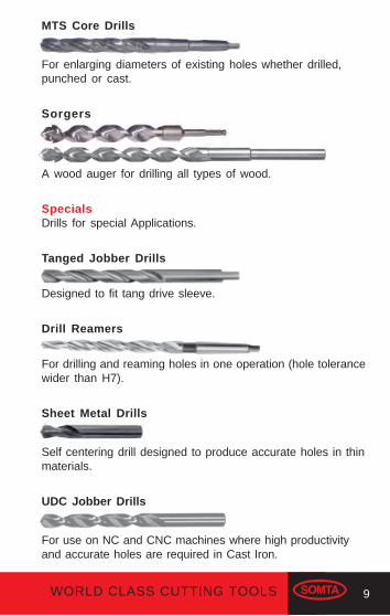
MTS Core Drills
For enlarging diameters of existing holes whether drilled,punched or cast.
Sorgers
A wood auger for drilling all types of wood.
SpecialsDrills for special Applications.
Tanged Jobber Drills
Designed to fit tang drive sleeve.
Drill Reamers
For drilling and reaming holes in one operation (hole tolerancewider than H7).
Sheet Metal Drills
Self centering drill designed to produce accurate holes in thinmaterials.
UDC Jobber Drills
For use on NC and CNC machines where high productivityand accurate holes are required in Cast Iron.
10 WORLD CLASS CUTTING TOOLS
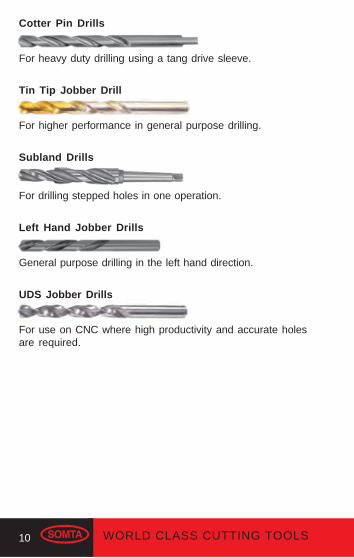
Cotter Pin Drills
For heavy duty drilling using a tang drive sleeve.
Tin Tip Jobber Drill
For higher performance in general purpose drilling.
Subland Drills
For drilling stepped holes in one operation.
Left Hand Jobber Drills
General purpose drilling in the left hand direction.
UDS Jobber Drills
For use on CNC where high productivity and accurate holesare required.
11WORLD CLASS CUTTING TOOLS
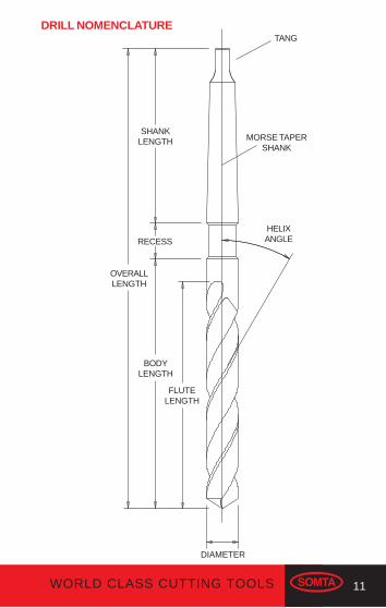
DRILL NOMENCLATURETANG
SHANKLENGTH
BODYLENGTH
FLUTELENGTH
DIAMETER
RECESS
OVERALLLENGTH
HELIXANGLE
MORSE TAPERSHANK
12 WORLD CLASS CUTTING TOOLS
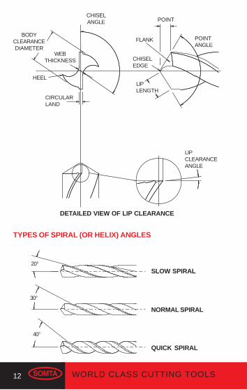
LIPCLEARANCEANGLE
BODYCLEARANCEDIAMETER
FLANK POINTANGLE
CHISELANGLE
WEBTHICKNESS
CIRCULARLAND
CHISELEDGE
LIPLENGTH
HEEL
DETAILED VIEW OF LIP CLEARANCE
POINT
TYPES OF SPIRAL (OR HELIX) ANGLES
20°
30°
40°
SLOW SPIRAL
NORMAL SPIRAL
QUICK SPIRAL

13WORLD CLASS CUTTING TOOLS
Standard Point
This point is suitable for general purpose drilling.
Split Point
The split point minimises end thrust and is self centering.
Long Point
Used for wood, plastic, hard rubber, fibres etc.
Cast Iron Point ("DX" Point)
The secondary angle reduces wear on the outer corners.
118°
125° - 135°
90°
125° - 135°
140° - 145°
118°
125° - 135°
70°
DRILL POINT STYLES

14 WORLD CLASS CUTTING TOOLS
Heavy Duty Notched Point
The notched point reduces end thrust and optimises centrecutting efficiency with chisel strength. It is recommended forhard and high strength materials.
Web Thinned Point
The web thinned point reduces end thrust and improves centrecutting efficiency.
"UX" Point
The 130° special notched "UX" point style provides self centering,easier penetration, improved hole accuracy and improved loaddistribution. This special notch geometry gives a corrected rakeangle of 15° which provides strong point for harder materials,as well as preventing snatching with materials such asAluminium, Brass, Bronze and Plastics. Available on UDL andUDS drills.
125° - 135°
125° - 135°
125° - 135°
118°
135°
130° 10% D

15WORLD CLASS CUTTING TOOLS
Part Split Point
The 130° part split point is similar to the conventional split point.The part split point has a wider chisel edge. Provides easypenetration, self centering and optimises centre cutting efficiencywith chisel strength.
130°
140° - 145°
Benefits of the Parabolic Flute FormHeavy web construction increases rigidity under torsional loadthus eliminating chatter at the cutting edges which cause edgebreak down and early failure. The Parabolic drill web is 50-90%thicker than the standard drill, depending on drill diameter.
Wider flute form, together with quicker spiral, promotes betterchip removal while allowing easier coolant flow to the drill point.
• Conventional Web • Parabolic Flute Form• Thicker Web
• Chipbreaker
FLUTE FORMS
16 WORLD CLASS CUTTING TOOLS
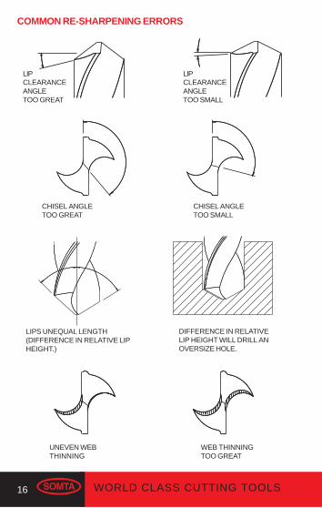
DIFFERENCE IN RELATIVELIP HEIGHT WILL DRILL ANOVERSIZE HOLE.
UNEVEN WEBTHINNING
WEB THINNINGTOO GREAT
LIPS UNEQUAL LENGTH(DIFFERENCE IN RELATIVE LIPHEIGHT.)
LIPCLEARANCEANGLETOO GREAT
LIPCLEARANCEANGLETOO SMALL
CHISEL ANGLETOO GREAT
CHISEL ANGLETOO SMALL
COMMON RE-SHARPENING ERRORS
17WORLD CLASS CUTTING TOOLS
STANDARD MORSE TAPER SHANK
To ISO 296 DIN 228 BS 1660
d b
R
e
D
a LL1
D1 d1
No.of
Taper
Fittingline
DiameterD
Diameterd
OverallLength
MaxL
D1 a MaxL1
Maxe
H13b
Maxd1
Taper /mm
on Dia
MaxR
123456
12.06517.78023.82531.26744.39963.348
9.014.019.025.036.052.0
65.580.099.0124.0156.0218.0
12.218.024.131.644.763.8
3.55.05.06.56.58.0
62.075.094.0117.5149.5210.0
13.516.020.024.029.040.0
5.26.37.911.915.919.0
8.713.518.524.535.751.0
5.06.07.08.010.013.0
0.049980.049950.050200.051940.052630.05214
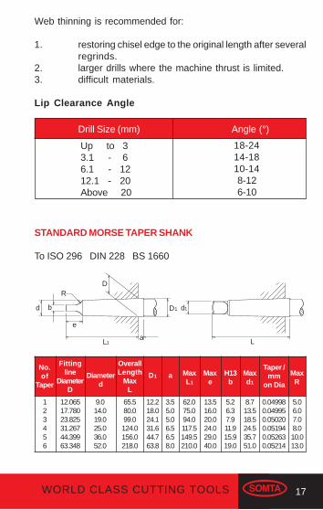
Web thinning is recommended for:
1. restoring chisel edge to the original length after severalregrinds.
2. larger drills where the machine thrust is limited.3. difficult materials.
Lip Clearance Angle
Drill Size (mm) Angle (°)
Up to 33.1 - 66.1 - 1212.1 - 20Above 20
18-2414-1810-14 8-12 6-10

18 WORLD CLASS CUTTING TOOLS
Multiple Diameter Drills
Specify whether drill is to be Step or Subland Type.D = Diameter of large, fluted section.P = Diameter of small, fluted section.A = Shank Diameter.L = Overall Length.F = Flute Length.E = Length of Small Diameter. This is measured from the extreme point to the bottom corner of the step angle.X°= Included angle of the step angle.S = Shank Length.
It is possible to drill two or more diameters in a hole onone operation with a correctly designed drill and theseare often used in mass production engineering.
Some of the hole types that can be drilled in a singleoperation.
If you have any cutting tool problem, please feel freeto contact our technical sales representatives.
D
E S
L
F
AP
X°
HOW TO ORDER SPECIALS

19WORLD CLASS CUTTING TOOLS
Modified Standards
There are many instances when a special tool (a tool not foundin the Somta catalogue or price list) can be manfactured from astandard product. We call this a ‘modified standard’.
Somta has both the capability and capacity to offer this servicewhich, under normal circumstances, means a short deliverytime.
The following are typical drill modifications:
Intermediate DiametersStandard sizes can be ground down to special diameters andtolerances.
Reduced Overall LengthsStandard drills can be cut to special lengths.
Drill PointsThe standard drill point angle is 118° included. This can be modifiedto any angle required. Many special points are available whichinclude web thinning, notch points, split points, double anglepoints, spur and brad points etc.
Tangs and FlatsTangs can be produced to DIN, ASA and ISO, also special whistlenotch flats on shanks.
Step DrillsStandard drills can be modified into step drills. (See drawing onpage 18).
Surface TreatmentsA full range of surface treatments including nitriding, streamoxide, chemical blackening, gold oxide and various PVD coatingsare available.

20 WORLD CLASS CUTTING TOOLS
When an intermediate diameter or a non standard length of drillis required, the following diameters and lengths need to bespecified.
Straight Shank Drills
D = Drill DiameterA = Shank DiameterL = Overall LengthF = Flute LengthS = Shank Length
Morse Taper Shank Drills
D = Drill DiameterL = Overall LengthF = Flute LengthM = Morse Taper Size
F
S
L
AD
F
L
D
M
21WORLD CLASS CUTTING TOOLS
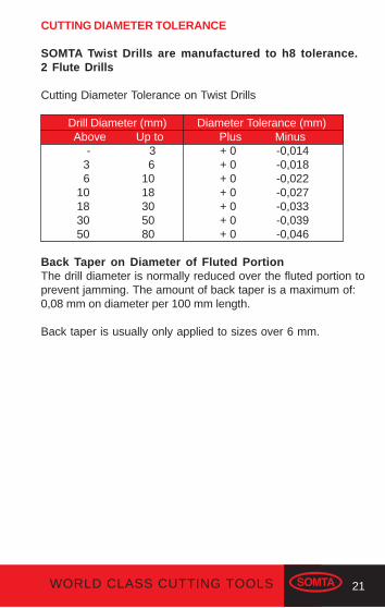
CUTTING DIAMETER TOLERANCE
SOMTA Twist Drills are manufactured to h8 tolerance.2 Flute Drills
Cutting Diameter Tolerance on Twist Drills
Drill Diameter (mm) Diameter Tolerance (mm) Above Up to Plus Minus - 3 + 0 -0,014 3 6 + 0 -0,018 6 10 + 0 -0,022 10 18 + 0 -0,027 18 30 + 0 -0,033 30 50 + 0 -0,039 50 80 + 0 -0,046
Back Taper on Diameter of Fluted PortionThe drill diameter is normally reduced over the fluted portion toprevent jamming. The amount of back taper is a maximum of:0,08 mm on diameter per 100 mm length.
Back taper is usually only applied to sizes over 6 mm.

22 WORLD CLASS CUTTING TOOLS
CORE DRILLING
Core Drill Nomenclature
OVERALL LENGTH
BODY
FLUTE LENGTH
RECESS SHANK
DIA
ME
TE
R
HELIXANGLE
LAND
BODYCLEARANCEDIAMETER
3 FLUTES
WEBLAND
4 FLUTES
BODYCLEARANCEDIAMETER
LIP CLEARANCEANGLE
CHAMFERLENGTH
LIPLENGTH

23WORLD CLASS CUTTING TOOLS
Cutting Diameter Tolerance on Core Drills
Core Drill Diameter (mm) Diameter Tolerance (mm) Above Up to Plus Minus - 6 + 0 - 0,018 6 10 + 0 - 0,022 10 18 + 0 - 0,027 18 30 + 0 - 0,033 30 50 + 0 - 0,039
A Guide to Core Drilling
Core drills are only used for enlarging diameters of existingholes whether drilled, punched or cored. Having no point, thedrill is only able to cut on the chamfer. The maximum amount ofmaterial that can be removed is restricted by the chamfer rootdiameter to 60% of the core drill diameter.
Because of its multi-flute construction the core drill gives betterhole size and surface finish than a two flute drill. Two flute drillsshould not be used to enlarge existing holes as they will tend tochip and break.
Speed and Feed rates for Core Drills
Speed - As for 2 flute drills
Feed - 3 Flute 1 to 1,5 x 2 flute drill feed rate
4 Flute 1,5 to 2 x 2 flute drill feed rate

24 WORLD CLASS CUTTING TOOLS
OVERALL LENGTH
FLUTELENGTH
PILOTLENGTH
60°118°
60° 120°
TYPE 'B'
TYPE 'R'
RADIUS
PILOTDIAMETER
BODY DIAMETER
TYPE 'A'
CENTRE DRILLS
Centre Drill Nomenclature
25WORLD CLASS CUTTING TOOLS
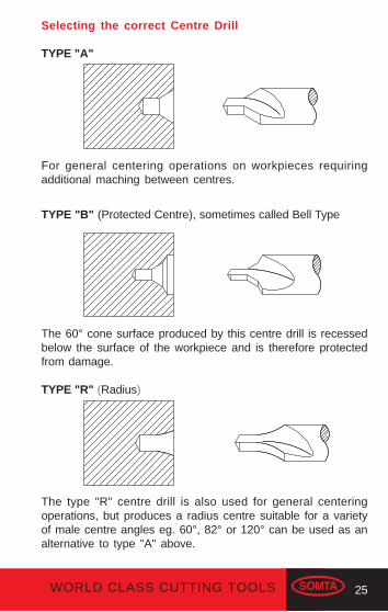
Selecting the correct Centre Drill
TYPE "A"
For general centering operations on workpieces requiringadditional maching between centres.
TYPE "B" (Protected Centre), sometimes called Bell Type
The 60° cone surface produced by this centre drill is recessedbelow the surface of the workpiece and is therefore protectedfrom damage.
TYPE "R" (Radius)
The type "R" centre drill is also used for general centeringoperations, but produces a radius centre suitable for a varietyof male centre angles eg. 60°, 82° or 120° can be used as analternative to type "A" above.

26 WORLD CLASS CUTTING TOOLS
The correct use of Centre Drills
A guide to successful drilling
Recommended SpeedsThe peripheral speeds for centre drills are the same as for 2flute drills given on page 34-35. For calculation purposes thenominal diameter given below should be used.
Centre Drill Nominal Centre Drill Nominal Size Diameter (mm) Size (mm) Diameter (mm)
BS 1 2 1 2 BS 2 3 1.25 2 BS 3 4 1.6 3 BS 4 6 2 4 BS 5 8 2.5 5 BS 6 11 3.15 6 BS 7 14 4 7
5 9 6.3 11 8 14 10 18
Recommended FeedsUse the nominal diameter given above to establish the feed asgiven on page 32-33, and then reduce by 40% for centre drills.
Re-sharpening of Centre DrillsCentre Drill can be re-sharpened on the point only. Refer to there-sharpening guide for 2 flute drill on page 16-17.

27WORLD CLASS CUTTING TOOLS
THE CORRECT USE OF DRILLS
A guide to successful drilling
• Make sure the workpiece is securely held and supported.Should it bend or move, it could cause the drill to break.
• Use a good socket and thoroughly clean both the socketand the taper shank of the drill. Do not use steel objects toseat the drill.
• Straight shank drill chucks must be able to hold the drillsecurely.
• Keep the drill sharp. Do not allow it to become blunt as itwill require extra-grinding to get it sharp again.
• Direct an adequate supply of the recommended coolant tothe point of the drill. (see page 34-35).
• Do not allow chips to clog the drill flutes.• When re-sharpening take care to achieve the correct point
geometry (see page 13-15) and do not overheat the drillwhen grinding.
• Use core drills for enlarging existing holes - 2 flute drillsare not designed for this purpose.
• Use the correct drill to suit the application (see page 5-10).
Deep Hole Drilling
A general guide
A hole deeper than 3 times its diameter is considered a “deephole”. Deep holes are successfully drilled by reducing speedand feed rates, as shown in the table on page 28. Care must betaken not to clog the flutes with chips.
In very deep holes it may be necessary to withdraw the drillfrequently to clear the flutes. Extra length drills should be usedwith a guide bush as close to the workpiece as possible tosupport the drill.
28 WORLD CLASS CUTTING TOOLS
Depth of Hole % SpeedReduction
Depth of Hole % FeedReduction
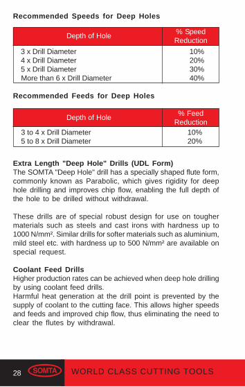
Recommended Speeds for Deep Holes
3 x Drill Diameter 10% 4 x Drill Diameter 20% 5 x Drill Diameter 30% More than 6 x Drill Diameter 40%
Recommended Feeds for Deep Holes
3 to 4 x Drill Diameter 10% 5 to 8 x Drill Diameter 20%
Extra Length "Deep Hole" Drills (UDL Form)The SOMTA "Deep Hole" drill has a specially shaped flute form,commonly known as Parabolic, which gives rigidity for deephole drilling and improves chip flow, enabling the full depth ofthe hole to be drilled without withdrawal.
These drills are of special robust design for use on toughermaterials such as steels and cast irons with hardness up to1000 N/mm². Similar drills for softer materials such as aluminium,mild steel etc. with hardness up to 500 N/mm² are available onspecial request.
Coolant Feed DrillsHigher production rates can be achieved when deep hole drillingby using coolant feed drills.Harmful heat generation at the drill point is prevented by thesupply of coolant to the cutting face. This allows higher speedsand feeds and improved chip flow, thus eliminating the need toclear the flutes by withdrawal.
29WORLD CLASS CUTTING TOOLS
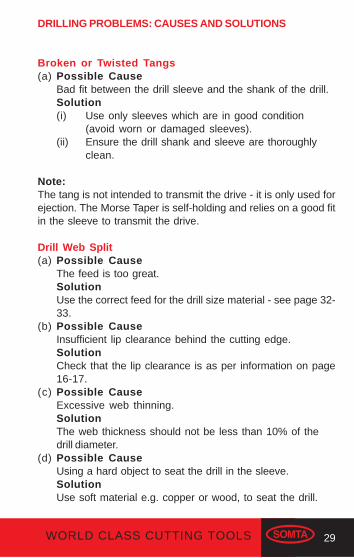
DRILLING PROBLEMS: CAUSES AND SOLUTIONS
Broken or Twisted Tangs(a) Possible Cause
Bad fit between the drill sleeve and the shank of the drill.Solution(i) Use only sleeves which are in good condition
(avoid worn or damaged sleeves).(ii) Ensure the drill shank and sleeve are thoroughly
clean.
Note:The tang is not intended to transmit the drive - it is only used forejection. The Morse Taper is self-holding and relies on a good fitin the sleeve to transmit the drive.
Drill Web Split(a) Possible Cause
The feed is too great.SolutionUse the correct feed for the drill size material - see page 32-33.
(b) Possible CauseInsufficient lip clearance behind the cutting edge.SolutionCheck that the lip clearance is as per information on page16-17.
(c) Possible CauseExcessive web thinning.SolutionThe web thickness should not be less than 10% of thedrill diameter.
(d) Possible CauseUsing a hard object to seat the drill in the sleeve.SolutionUse soft material e.g. copper or wood, to seat the drill.
30 WORLD CLASS CUTTING TOOLS
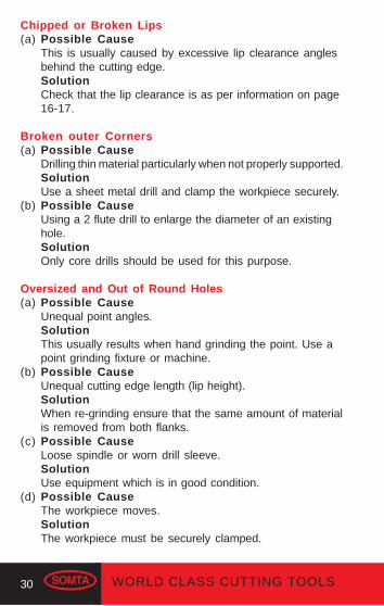
Chipped or Broken Lips(a) Possible Cause
This is usually caused by excessive lip clearance anglesbehind the cutting edge.SolutionCheck that the lip clearance is as per information on page16-17.
Broken outer Corners(a) Possible Cause
Drilling thin material particularly when not properly supported.SolutionUse a sheet metal drill and clamp the workpiece securely.
(b) Possible CauseUsing a 2 flute drill to enlarge the diameter of an existinghole.SolutionOnly core drills should be used for this purpose.
Oversized and Out of Round Holes(a) Possible Cause
Unequal point angles.SolutionThis usually results when hand grinding the point. Use apoint grinding fixture or machine.
(b) Possible CauseUnequal cutting edge length (lip height).SolutionWhen re-grinding ensure that the same amount of materialis removed from both flanks.
(c) Possible CauseLoose spindle or worn drill sleeve.SolutionUse equipment which is in good condition.
(d) Possible CauseThe workpiece moves.SolutionThe workpiece must be securely clamped.

31WORLD CLASS CUTTING TOOLS
Cracks in cutting edges(a) Possible Cause
The point is overheated and cooled too quickly when re-sharpening.SolutionUse coolant when grinding or grind in stages, quenchingfrequently in soluble oil.
Worn outer Corners(a) Possible Cause
The peripheral speed is too high for the material beingdrilled.SolutionUse the recommended speed - see page 34-35.
Drill rubbing and not cutting(a) Possible Cause
Too little lip clearance behind the cutting edge.SolutionCheck that the lip clearance is as per information on page16-17.
Drill breaks at flute runout(a) Possible Cause
The workpiece moves during drilling.SolutionThe workpiece must be securely clamped.
(b) Possible CauseThe flutes are clogged with swarf.SolutionClear the flutes by frequently withdrawing the drill, or use adrill more suited to the material e.g. a UDL drill for aluminium.
(c) Possible CauseUsing the wrong type of drill e.g. using a jobber drill for thinmaterial.SolutionSee pages 5-10 for the correct drill to suit the application.
32 WORLD CLASS CUTTING TOOLS
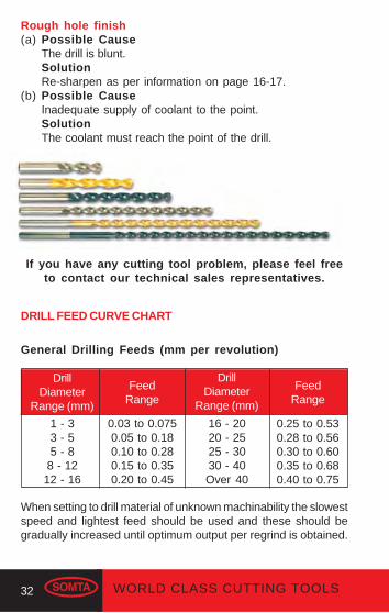
When setting to drill material of unknown machinability the slowestspeed and lightest feed should be used and these should begradually increased until optimum output per regrind is obtained.
Rough hole finish(a) Possible Cause
The drill is blunt.SolutionRe-sharpen as per information on page 16-17.
(b) Possible CauseInadequate supply of coolant to the point.SolutionThe coolant must reach the point of the drill.
If you have any cutting tool problem, please feel freeto contact our technical sales representatives.
DRILL FEED CURVE CHART
General Drilling Feeds (mm per revolution)
DrillDiameter
Range (mm)
FeedRange
DrillDiameter
Range (mm)
FeedRange
1 - 33 - 55 - 88 - 12
12 - 16
0.03 to 0.0750.05 to 0.180.10 to 0.280.15 to 0.350.20 to 0.45
16 - 2020 - 2525 - 3030 - 40Over 40
0.25 to 0.530.28 to 0.560.30 to 0.600.35 to 0.680.40 to 0.75
33WORLD CLASS CUTTING TOOLS
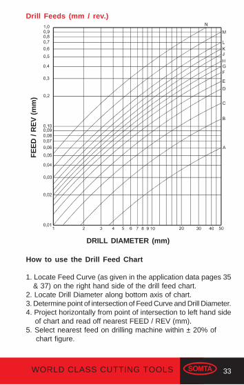
Drill Feeds (mm / rev.)
FE
ED
/ R
EV
(m
m)
DRILL DIAMETER (mm)
How to use the Drill Feed Chart
1. Locate Feed Curve (as given in the application data pages 35 & 37) on the right hand side of the drill feed chart.2. Locate Drill Diameter along bottom axis of chart.3. Determine point of intersection of Feed Curve and Drill Diameter.4. Project horizontally from point of intersection to left hand side of chart and read off nearest FEED / REV (mm).5. Select nearest feed on drilling machine within ± 20% of chart figure.
34 WORLD CLASS CUTTING TOOLS
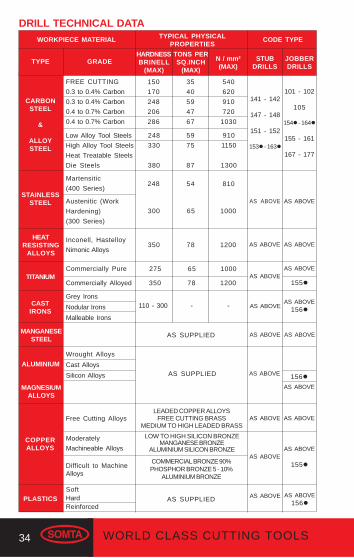
WORKPIECE MATERIAL
TYPE GRADE
CARBONSTEEL
&
ALLOYSTEEL
TYPICAL PHYSICALPROPERTIES
CODE TYPE
FREE CUTTING
0.3 to 0.4% Carbon
0.3 to 0.4% Carbon
0.4 to 0.7% Carbon
0.4 to 0.7% Carbon
HARDNESSBRINELL
(MAX)
TONS PERSQ.INCH
(MAX)
N / mm²(MAX)
STAINLESSSTEEL
HEATRESISTING
ALLOYS
TITANIUM
CASTIRONS
150
170
248
206
286
35
40
59
47
67
540
620
910
720
1030
Low Alloy Tool Steels
High Alloy Tool Steels
Heat Treatable Steels
Die Steels
248
330
380
59
75
87
910
1150
1300
Martensitic
(400 Series)248
Austenitic (Work
Hardening)
(300 Series)
300
54
65
810
1000
Inconell, Hastelloy
Nimonic Alloys350 78 1200
Commercially Pure
Commercially Alloyed
275
350
65
78
1000
1200
Grey Irons
Nodular Irons
Malleable Irons
110 - 300 - -
MANGANESESTEEL
ALUMINIUM
MAGNESIUMALLOYS
COPPERALLOYS
PLASTICS
AS SUPPLIED
Wrought Alloys
Cast Alloys
Silicon Alloys
Moderately
Machineable Alloys
LEADED COPPER ALLOYSFREE CUTTING BRASS
MEDIUM TO HIGH LEADED BRASS
LOW TO HIGH SILICON BRONZEMANGANESE BRONZE
ALUMINIUM SILICON BRONZE
COMMERCIAL BRONZE 90%PHOSPHOR BRONZE 5 - 10%
ALUMINIUM BRONZE
SoftHardReinforced
Free Cutting Alloys
Difficult to MachineAlloys
DRILL TECHNICAL DATA
AS SUPPLIED
AS SUPPLIED
141 - 142
147 - 148
151 - 152
153 - 163
STUBDRILLS
JOBBERDRILLS
101 - 102
105
154 - 164
155 - 161
167 - 177
AS ABOVE
AS ABOVE
AS ABOVE
AS ABOVE
AS ABOVE
AS ABOVE
AS ABOVE
AS ABOVE
155
AS ABOVE
AS ABOVE
AS ABOVE
AS ABOVE
155
AS ABOVE156
AS ABOVE
156
AS ABOVE
AS ABOVE
AS ABOVE
AS ABOVE156

35WORLD CLASS CUTTING TOOLS
LONGSERIES
SPEEDMETRES /
MINCOOLANT
SOLUBLE OIL
OR
SEMI-
SYNTHETIC
OIL
25 - 30
15 - 20
10 - 15
15 - 24
10 - 15
4 - 8
12 - 16
6
5 - 10
15 - 25
7 - 11
25 - 35
15 - 30
25 - 30
4 - 6
Up to 45
30 - 35
40 - 100
40 - 50
30 - 36
15 - 20
25 - 30
< 20
FEEDCURVESee Page
32-33
H
F
H
H
C
E
F
C
K
C
L
L
M
L
-
SOLUBLE OIL
SOLUBLE OILEXTREME
PRESSURE
SOLUBLE OILEXTREME
PRESSUREOR
SULPHO-CHLORINATED
SOLUBLE OILEXTREME PRESSURE
ORSULPHO-CHLORINATED
SOLUBLE OILSULPHO-CHLORINATED
EXTREME PRESSURECHLORINATED OIL
DRY ORDETERGENT
WATER - SOLUBLEEMULSION
DRY OR
NEAT E.P. OIL
SOLUBLE OIL
(1 : 25)
LOW VISCOSITY
MINERAL OIL
SOLUBLE OIL
(1 : 20)
SOLUBLE OIL(1 : 20)
LIGHT MINERALOIL
DRY OR
SOLUBLE OIL
DRILL TECHNICAL DATA (cont.)
EXTRALENGTH
MORSETAPER
STANDARD
MORSETAPER
E/LENGTH
CODE TYPE DENOTES RECOMMENDED
116 - 117
109 - 110
118 - 119
120 - 121
122 - 123
124 - 125
126
201 - 202
203 - 204
205 - 206
208
241 - 242
244 - 245
251 - 252
254 - 255
AS ABOVE AS ABOVEAS ABOVE
261279
AS ABOVE
AS ABOVE AS ABOVEAS ABOVE
261279
AS ABOVE
AS ABOVE AS ABOVEAS ABOVE
261279
AS ABOVE
AS ABOVE AS ABOVE AS ABOVE AS ABOVE
AS ABOVE AS ABOVEAS ABOVE
261279
AS ABOVE
AS ABOVE AS ABOVE AS ABOVE AS ABOVE
AS ABOVE AS ABOVE AS ABOVE AS ABOVE
36 WORLD CLASS CUTTING TOOLS
8501200
1200
850
850
1000
500
7001000
350
250
250
300
150
250350
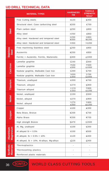
UD DRILL TECHNICAL DATA
Free Cutting steels
Structural steel. Case carburizing steel
Plain carbon steel
Alloy steel
Alloy steel. Hardened and tempered steel
Alloy steel. Hardened and tempered steel
Free machining Stainless steel
Austenit ic
Ferritic + Austenitic, Ferritic, Martensitic
Lamellar graphite
Lamellar graphite
Nodular graphite, Malleable Cast Iron
Nodular graphite, Malleable Cast Iron
Titanium, unalloyed
Titanium, alloyed
Titanium alloyed
Nickel, unalloyed
Nickel, alloyed
Nickel, alloyed
Copper
Beta Brass, Bronze
Alpha Brass
High strength Bronze
Al, Mg, unalloyed
Al alloyed Si < 0.5%
Al alloyed, Si > 0.5% < 10%
Al alloyed, Si > 10%, Al-alloys, Mg-alloys
Thermoplastics
Thermosetting plastics
Reinforced plastic materials
MATERIAL TYPESHARDNESS
HB
TENSILESTRENGTH
N/mm²
Ste
elS
tain
less
Ste
elC
ast I
ron
Tit
aniu
mN
icke
lC
op
per
Alu
min
ium
Mag
nes
ium
Syn
thet
icM
ater
ials
120
200
250
250
150300
200
200300
200
270
270350
150
270
270350
100
200
200
470
100
150
120
120
-
-
-
400
700
850
850
5001000
700
9001200
500
900
9001200
350
700
700
1500
350
500
400
400
-
-
-
700
900

37WORLD CLASS CUTTING TOOLS
SURFACE SPEEDMETRES
PER MINUTE
FEEDCURVE
see Page 32-33
DRILL TYPE &SURFACE
TREATMENT
NORMALCHIPFORM
extra long
middle/long
long
long
long
long
middle
long
long
extra short
extra short
middle/short
middle/short
extra long
middle/short
middle/short
extra long
long
long
extra long
middle/short
long
short
extra long
middle
middle/short
short
extra long
short
extra short UDCTiN
15 - 2020 - 30
JL
UDLTiNUDLTiNUDL
TiN TiCN TiAlNUDL
TiN TiCN TiAlNUDL
TiN TiCN TiAlNUDL
TiN TiCN TiAlNUDL
TiN TiCN TiAlNUDL
TiN TiCN TiAlNUDL
TiN TiCN TiAlNUDC
TiAlNUDC
TiAlNUDC
TiAlNUDC
TiAlNUDLTiCNUDSTiCNUDSTiCNUDL
TiCN TiAlNUDL
TiCN TiAlNUDL
TiCN TiAlNUDLTiNUDSTiNUDLTiNUDSTiNUDLTiNUDLTiNUDSTiNUDSTiNUDLTiNUDSTiN
35 - 4550 - 7025 - 3540 - 5025 - 3035 - 4025 - 3035 - 4015 - 2025 - 3015 - 2020 - 2518 - 2127 - 328 - 10
12 - 1510 - 1516 - 2230 - 3545 - 5525 - 3035 - 4518 - 2125 - 3512 - 1722 - 2620 - 2530 - 3513 - 1720 - 25
5 - 67 - 11
12 - 1620 - 25
6 - 810 - 12
5 - 610 - 1255 - 6580 - 9560 - 70
90 - 10530 - 4045 - 5027 - 3340 - 5075 - 85
110 - 12565 - 75
100 - 11555 - 65
80 - 10027 - 3340 - 5075 - 85
110 - 12555 - 65
80 - 100
HJHJGIGIEGEGEG
KMEGGIGIEGEGEGEGCEGIGICELNLNLNKMNNNNLNKMLNJL
UD DRILL TECHNICAL DATA (cont.)
38 WORLD CLASS CUTTING TOOLS
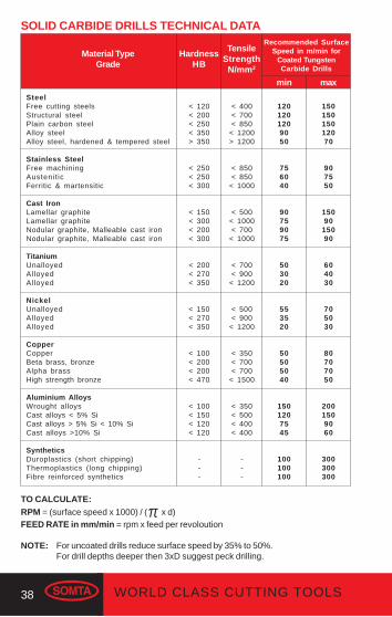
SOLID CARBIDE DRILLS TECHNICAL DATA
HardnessHB
Material TypeGrade
SteelFree cutting steelsStructural steelPlain carbon steelAlloy steelAlloy steel, hardened & tempered steel
Stainless SteelFree machiningAustenit icFerritic & martensitic
Cast IronLamellar graphiteLamellar graphiteNodular graphite, Malleable cast ironNodular graphite, Malleable cast iron
TitaniumUnalloyedAlloyedAlloyed
NickelUnalloyedAlloyedAlloyed
CopperCopperBeta brass, bronzeAlpha brassHigh strength bronze
Aluminium AlloysWrought alloysCast alloys < 5% SiCast alloys > 5% Si < 10% SiCast alloys >10% Si
SyntheticsDuroplastics (short chipping)Thermoplastics (long chipping)Fibre reinforced synthetics
1201201209050
756040
90759075
503020
553520
50505040
1501207545
100100100
Recommended SurfaceSpeed in m/min for
Coated TungstenCarbide Drills
< 120< 200< 250< 350> 350
< 250< 250< 300
< 150< 300< 200< 300
< 200< 270< 350
< 150< 270< 350
< 100< 200< 200< 470
< 100< 150< 120< 120
---
min max
< 400< 700< 850
< 1200> 1200
< 850< 850
< 1000
< 500< 1000< 700
< 1000
< 700< 900
< 1200
< 500< 900
< 1200
< 350< 700< 700
< 1500
< 350< 500< 400< 400
---
TensileStrength
N/mm2
15015015012070
907550
15090
15090
604030
705030
80707050
2001509060
300300300
TO CALCULATE:RPM = (surface speed x 1000) / (π x d)FEED RATE in mm/min = rpm x feed per revoloution
NOTE: For uncoated drills reduce surface speed by 35% to 50%.For drill depths deeper then 3xD suggest peck drilling.

39WORLD CLASS CUTTING TOOLS
Recommended feed in mm per revolutionfor Coated Tungsten Carbide Drills
Drill Diameter in mm
0.030.030.030.020.02
0.020.020.02
0.030.020.030.02
0.020.020.02
0.020.020.02
0.030.020.020.02
0.030.030.030.03
0.040.040.04
1
0.050.050.050.040.04
0.040.030.04
0.050.040.050.04
0.040.040.03
0.040.040.03
0.050.040.040.04
0.060.060.060.06
0.070.080.07
2
0.080.080.080.060.05
0.050.050.05
0.080.060.080.06
0.060.060.05
0.060.060.05
0.080.060.060.06
0.090.090.090.09
0.110.120.11
3
0.300.300.300.240.18
0.220.190.22
0.300.240.300.24
0.240.240.18
0.240.240.19
0.300.240.240.24
0.360.360.360.36
0.420.480.42
12
0.100.100.100.080.06
0.070.070.07
0.100.080.100.08
0.080.080.06
0.080.080.07
0.100.080.080.08
0.120.120.120.12
0.140.160.14
4
0.130.130.130.100.08
0.090.080.09
0.130.100.130.10
0.100.100.08
0.100.100.08
0.130.100.100.10
0.150.150.150.15
0.180.200.18
5
0.250.250.250.200.15
0.180.160.18
0.250.200.250.20
0.200.200.15
0.200.200.16
0.250.200.200.20
0.300.300.300.30
0.350.400.35
10
0.200.200.200.160.12
0.140.130.14
0.200.160.200.16
0.160.160.12
0.160.160.13
0.200.160.160.16
0.240.240.240.24
0.280.320.28
8
0.150.150.150.120.09
0.110.100.11
0.150.120.150.12
0.120.120.09
0.120.120.10
0.150.120.120.12
0.180.180.180.18
0.210.240.21
6
0.330.330.330.260.20
0.230.210.23
0.330.260.330.26
0.260.260.20
0.260.260.21
0.330.260.260.26
0.390.390.390.39
0.460.520.46
13
0.350.350.350.280.21
0.250.220.25
0.350.280.350.28
0.280.280.21
0.280.280.22
0.350.280.280.28
0.420.420.420.42
0.490.560.49
14
0.400.400.400.320.24
0.290.260.29
0.400.320.400.32
0.320.320.24
0.320.320.26
0.400.320.320.32
0.480.480.480.48
0.480.640.48
16
SOLID CARBIDE DRILLS TECHNICAL DATA (cont.)
% feed reduction for deep hole drilling
Hole Depth % reduction
3 x drill diameter4 x drill diameter5 x drill diameter
> 6 x drill diameter
10%20%30%40%

40 WORLD CLASS CUTTING TOOLS
SELECTING THE CORRECT REAMER, COUNTERSINK &COUNTERBORE
Standard Reamers, Countersinks & CounterboresThe following are available ex-stock from Somta.
Parallel Shank Countersinks
MTS Countersinks
To produce a countersink suitable for countersunk head screws,also used as a deburring tool.
Parallel Shank Counterbores
MTS Counterbores
For counterboring holes to suit capscrew heads.
Parallel Hand Reamers
General hand reaming.
MTS Parallel Machine Reamers
General machine reaming.
REAMERS, COUNTERSINKS & COUNTERBORES
41WORLD CLASS CUTTING TOOLS
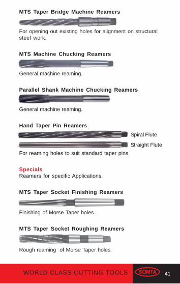
MTS Taper Bridge Machine Reamers
For opening out existing holes for alignment on structuralsteel work.
MTS Machine Chucking Reamers
General machine reaming.
Parallel Shank Machine Chucking Reamers
General machine reaming.
Hand Taper Pin Reamers
For reaming holes to suit standard taper pins.
SpecialsReamers for specific Applications.
MTS Taper Socket Finishing Reamers
Finishing of Morse Taper holes.
MTS Taper Socket Roughing Reamers
Rough reaming of Morse Taper holes.
Straight Flute
Spiral Flute

42 WORLD CLASS CUTTING TOOLS
REAMERS
Reamer Nomenclature
SECTION A-A
NO CIRCULARLAND
BEVEL LEADANGLE
TAPER LEAD
BB
AA
TAPER LEADANGLE
SHANK
SQUARE
SIZE OFSQUARE
DIA
ME
TE
R
OVERALL LENGTH
CUTTING LENGTH RECESS SHANK
B
B
DIA
ME
TE
R
PRIMARYCLEARANCEANGLE
CLEARANCEANGLE
CIRCULARLAND
SECTION B-B
CIRCULARLAND
CLEARANCEANGLE
FLUTE
CENTRE HOLE
RADIAL FACECUTTING EDGE
FRONT END VIEW OF PARALLELMACHINE REAMER
MORSE TAPER
43WORLD CLASS CUTTING TOOLS
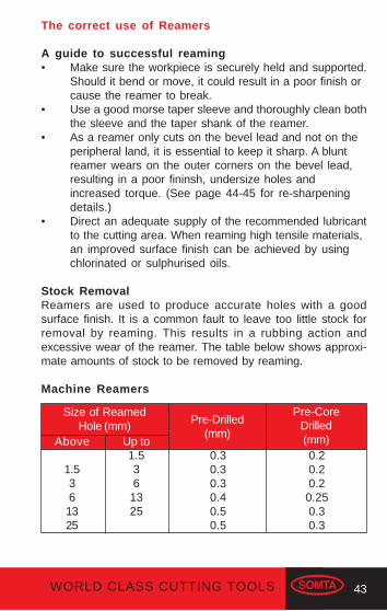
The correct use of Reamers
A guide to successful reaming• Make sure the workpiece is securely held and supported.
Should it bend or move, it could result in a poor finish orcause the reamer to break.
• Use a good morse taper sleeve and thoroughly clean boththe sleeve and the taper shank of the reamer.
• As a reamer only cuts on the bevel lead and not on theperipheral land, it is essential to keep it sharp. A bluntreamer wears on the outer corners on the bevel lead,resulting in a poor fininsh, undersize holes andincreased torque. (See page 44-45 for re-sharpeningdetails.)
• Direct an adequate supply of the recommended lubricantto the cutting area. When reaming high tensile materials,an improved surface finish can be achieved by usingchlorinated or sulphurised oils.
Stock RemovalReamers are used to produce accurate holes with a goodsurface finish. It is a common fault to leave too little stock forremoval by reaming. This results in a rubbing action andexcessive wear of the reamer. The table below shows approxi-mate amounts of stock to be removed by reaming.
Machine Reamers
Above
1.5361325
Up to1.536
1325
Pre-Drilled(mm)
Pre-CoreDrilled(mm)
0.30.30.30.40.50.5
0.20.20.20.250.30.3
Size of ReamedHole (mm)
44 WORLD CLASS CUTTING TOOLS
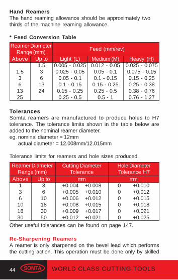
Reamer DiameterRange (mm)
Feed (mm/rev)
Above
1.536
1325
Up to1.536
1324
Light (L)0.005 - 0.0250.025 - 0.05
0.05 - 0.10.1 - 0.15
0.15 - 0.250.25 - 0.5
Medium (M)0.012 - 0.05
0.05 - 0.10.1 - 0.150.15 - 0.250.25 - 0.5
0.5 - 1
Heavy (H)0.025 - 0.0750.075 - 0.150.15 - 0.250.25 - 0.380.38 - 0.760.76 - 1.27
TolerancesSomta reamers are manufactured to produce holes to H7tolerance. The tolerance limits shown in the table below areadded to the nominal reamer diameter.eg. nominal diameter = 12mm actual diameter = 12.008mm/12.015mm
Tolerance limits for reamers and hole sizes produced.
Reamer DiameterRange (mm)
Cutting DiameterTolerance
Above136101830
Up to3610183050
mm+0.004 +0.008+0.005 +0.010+0.006 +0.012+0.008 +0.015+0.009 +0.017+0.012 +0.021
mm0 +0.0100 +0.0120 +0.0150 +0.0180 +0.0210 +0.025
Hole DiameterTolerance H7
Other useful tolerances can be found on page 147.
Hand ReamersThe hand reaming allowance should be approximately twothirds of the machine reaming allowance.
* Feed Conversion Table
Re-Sharpening ReamersA reamer is only sharpened on the bevel lead which performsthe cutting action. This operation must be done only by skilled

45WORLD CLASS CUTTING TOOLS
SHANK DIAMETER
SHANK
LENGTH
PILOT
PILOT DIAMETER
RECESS
BODY
BODY DIAMETER
COUNTERBORES
Counterbore Nomenclature
operators on appropriate machine tools. When re-sharpening itis essential to maintain both the original relief angle of 6°- 8° andthe concentricity of the bevel lead.

46 WORLD CLASS CUTTING TOOLS
The correct use of Counterbores
A General GuideCounterbores are used to create seatings for cap screw headsand are therefore identified by the cap screw they suit. Theyare available with straight or Morse Taper shanks.
Cap Screw Pilot Drill Counterbore Size Size (mm) Diameter (mm) M 3 3.4 6 M 3.5 3.9 6.5 M 4 4.5 8 M 5 5.5 10 M 6 6.6 11 M 8 9 15 M 10 11 18 M 12 14 20
Speeds & FeedsThe speeds and feeds for counterbores are approximately 80%to 85% of those for drills as given on page 34-35.The counterbore diameter given in the above table is used forthis calculation.
Re-Sharpening CounterboresCounterbores are re-sharpened only by grinding the front cuttingedges, maintaining the original relief angle of 6°- 8°.
47WORLD CLASS CUTTING TOOLS
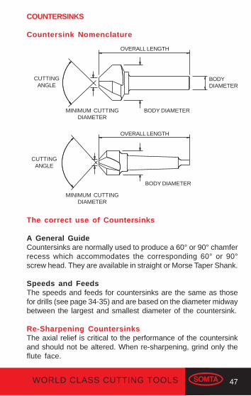
The correct use of Countersinks
A General GuideCountersinks are normally used to produce a 60° or 90° chamferrecess which accommodates the corresponding 60° or 90°screw head. They are available in straight or Morse Taper Shank.
Speeds and FeedsThe speeds and feeds for countersinks are the same as thosefor drills (see page 34-35) and are based on the diameter midwaybetween the largest and smallest diameter of the countersink.
Re-Sharpening CountersinksThe axial relief is critical to the performance of the countersinkand should not be altered. When re-sharpening, grind only theflute face.
OVERALL LENGTH
CUTTINGANGLE
BODYDIAMETER
MINIMUM CUTTINGDIAMETER
BODY DIAMETER
CUTTINGANGLE
MINIMUM CUTTINGDIAMETER
BODY DIAMETER
OVERALL LENGTH
COUNTERSINKS
Countersink Nomenclature

48 WORLD CLASS CUTTING TOOLS
REAMING PROBLEMS: CAUSES AND SOLUTIONS
Poor Surface Finish(a) Possible Cause
Incorrect speed and/or feed.SolutionUse the recommended speed/feed - see page 50-51.
(b) Possible CauseA Worn reamerSolutionDo not allow the reamer to become too blunt. See page 44-45 for re-sharpening details.
(c) Possible CauseInsufficient or wrong type of lubricant.SolutionApply an adequate supply of the correct lubricant to thecutting area. See the drill table on page 34-35 for therecommended lubricants.
(d) Possible CauseDamaged cutting edges.SolutionUse a reamer which is in good condition.
Reamer Chattering(a) Possible Cause
Lack of rigidity in set up.SolutionOnly use equipment which is in good condition and makesure the workpiece is securely held.
(b) Possible CauseFeed too low.SolutionUse the recommended speed/feed - see page 50-51.
Reamer showing rapid wear(a) Possible Cause
Too little stock in the hole for reaming causing the reamerto rub and not cut.

49WORLD CLASS CUTTING TOOLS
Solutionsee page 43 for recommended stock removal.
(b) Possible CauseSpeed too high or feed too low.SolutionUse the recommended speed/feed - see page 50-51.
(c) Possible CauseThe workpiece material is too hard.SolutionUse a HSS-Co reamer.
Tapered or Bell-Mouthed holes(a) Possible Cause
Mis-alignment of the reamer and the hole.SolutionAlign the reamer and the hole.
(b) Possible CauseThe machine spindle and/or bearings are worn.SolutionOnly use equipment which is in good condition.
Reamer rubbing and not cutting(a) Possible Cause
Too little reaming allowance in the hole.SolutionSee table of stock removal on page 43.
(b) Possible CauseReamer re-sharpened with too little or no relief on thebevel lead.SolutionRe-grind the bevel lead to a 6°- 8° relief.
Oversized holes(a) Possible Cause
Excessive run-out on the machine spindle or holdingdevice eg. taper sleeve, collet or chuck.SolutionOnly use equipment which is in good conditon.

50 WORLD CLASS CUTTING TOOLS
†Speedm/min
*Typeof
FeedTYPE GRADE
CARBONSTEEL
&
ALLOYSTEEL
FREE CUTTING
0.3 to 0.4% Carbon
0.3 to 0.4% Carbon
0.4 to 0.7% Carbon
0.4 to 0.7% Carbon
HARDNESS
BRINELL
TONS PER SQIN. (MAX)
N/mm²(MAX)
150
170
248
206
286
35
40
59
47
67
525
600
900
700
1000
248
330
380
59
75
87
900
1125
1300
STAINLESSSTEEL
MartensiticFree Cutting
MartensiticStd. Grade
AusteniticFree Cutting
Austenitic Std. Grade
12-15
7-10
5-8
M-H
M
L
7-10
5-8
2-4
5-8
2-5
M
L-M
5-8
2-5
L-M
L-M
As Supplied
380 54 810
TITANIUM
Titanium Comm: Pure
Titanium Comm: Pure
Titanium Comm: Pure
Titanium Alloyed
Titanium Alloyed
NIMONICALLOYS
Wrought
Cast
300
350
67
78
1000
12002-5 L
170
200
275
340
380
40
43
65
76
85
600
650
975
1140
1275
7-10 M
2-4 L-M
TOOLSTEEL
HSS Standard
Grades
HSS Cobalt Grades
Hot Working Steel
Cold Working Steel
225
225
48
54
720
800
7-10 M
REAMER TECHNICAL DATA
† See Speed Conversion Chart on page 148-149.* See table on page 44.
M
M
L
TYPICAL PHYSICALPROPERTIES
51WORLD CLASS CUTTING TOOLS
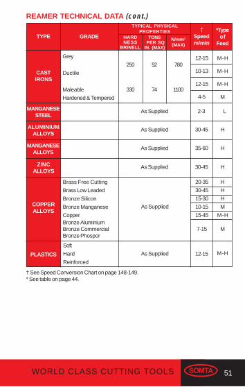
REAMER TECHNICAL DATA (cont.)
† See Speed Conversion Chart on page 148-149.* See table on page 44.
†Speedm/min
*Typeof
FeedTYPE GRADE
CASTIRONS
Grey
Ductile
Maleable
Hardened & Tempered
HARDNESS
BRINELL
N/mm²(MAX)
MANGANESESTEEL
250
330
52
74
780
1100
As Supplied
COPPERALLOYS
12-15
10-13
12-15
4-5
2-3
20-35
30-45
15-30
10-15
15-45
7-15
H
H
H
M
M-H
M
As Supplied
Brass Free Cutting
Brass Low Leaded
Bronze Silicon
Bronze Manganese
CopperBronze AluminiumBronze CommercialBronze Phospor
12-15 M-HPLASTICS
Soft
Hard
Reinforced
M-H
M-H
M-H
M
L
ALUMINIUMALLOYS
As Supplied 30-45 H
MANGANESEALLOYS
As Supplied 35-60 H
ZINCALLOYS
As Supplied 30-45 H
As Supplied
TYPICAL PHYSICALPROPERTIES
TONS PER SQIN. (MAX)
52 WORLD CLASS CUTTING TOOLS
SELECTING THE CORRECT TAP
Short Hand Taps
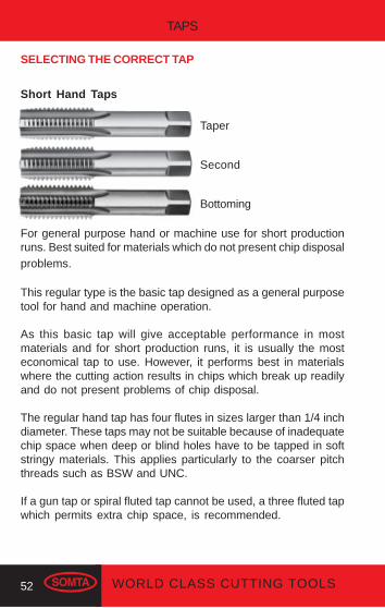
For general purpose hand or machine use for short productionruns. Best suited for materials which do not present chip disposalproblems.
This regular type is the basic tap designed as a general purposetool for hand and machine operation.
As this basic tap will give acceptable performance in mostmaterials and for short production runs, it is usually the mosteconomical tap to use. However, it performs best in materialswhere the cutting action results in chips which break up readilyand do not present problems of chip disposal.
The regular hand tap has four flutes in sizes larger than 1/4 inchdiameter. These taps may not be suitable because of inadequatechip space when deep or blind holes have to be tapped in softstringy materials. This applies particularly to the coarser pitchthreads such as BSW and UNC.
If a gun tap or spiral fluted tap cannot be used, a three fluted tapwhich permits extra chip space, is recommended.
TAPS
Taper
Second
Bottoming

53WORLD CLASS CUTTING TOOLS
Rougher
Intermediate
Finisher
Left Hand Short Hand Taps
For general purpose hand or machine use for short productionruns. Best suited for materials which do not present chip disposalproblems.
Serial Hand Taps
Serial taps comprise of one or more undersized roughing tapswhich remove most of the material before final sizing with afinishing tap.
Some reasons for using serial taps are:
(a) The toughness of the material being tapped.(b) The amount of material to be removed could cause
swarf choking with a single tap.(c) The very small tolerance on pitch diameter.(d) An extremely good finish required.
For general purpose machine or hand use in tough materials,producing accurate threads with a high finish. Used in sequenceto remove most of the material in stages before finally sizingwith the finishing tap.
Cutting tools may shattereye protection should be worn

54 WORLD CLASS CUTTING TOOLS
Spiral Flute Short Machine Taps
Mainly for work in blind holes and on ductile materials, such asaluminium and zinc alloys, which produce long stringy chips.The taps have a 15° or 35° right hand helix. The flute shapeeliminates clogging and jamming, resulting in improved tap life.
These taps are designed primarliy for machine tapping of blindholes, are used to the best advantage in materials which producelong stringy chips. The shearing action provided by the spiralflutes produces a better finish on difficult to machine metals andcauses the chips to be drawn back, eliminating clogging at thecutting chamfer.
Gun Nose (Spiral Point) Short Machine Taps
For machine use on through holes. Suitable for a wide range ofmaterials. The gun nose creates chip disposal ahead of the tapwhile the flute geometry allows an adequate supply of lubricantto the cutting area, making higher tapping speed possible.
Gun nose taps have straight flutes supplemented by angularcutting faces at the point. These faces cut with a shearingaction which propels the chips ahead of the tap leaving theflutes clear for the free flow of coolant to the point.
Primarily designed for use in through holes, these taps can beused in blind holes providing that there is ample clearancebeyond the threaded section to accomodate the chips. Theadvantages of a gun nose tap are, the shearing action of theangular cutting faces which produce a fine finish on the threadsand, shallower flutes which permit a stronger cross sectionthroughout the tap.
15° Spiral Flute
35° Spiral Flute

55WORLD CLASS CUTTING TOOLS
Pipe Taps
For machine use on pipe work for parallel threads.
For machine use on pipe work for tapered threads.
Pipe taps are supplied with PARALLEL threads or with TAPERthreads. These taps are shorter than a similar size of regularhand tap, but the design features are the same. They are suitablefor hand or machine use.
Colour Band Application (CBA) Taps
The primary benefit of the CBA range is enhanced threadingperformance due to geometry designed for specific materialapplication groups. The result is an improved quality of finishand an increased number of holes per tap, giving extended taplife and reduced cost per hole. Manufactured from HSSE-V3steel (High Vanadium) for greater wear resistance.

56 WORLD CLASS CUTTING TOOLS
Yellow Band
Designed for more ductile materials such as Aluminium,Magnesium Alloys, Soft Brass (MS58), Plastics, Zinc Alloys andCopper. Used to tap materials with hardness up to 200HB, tensilestrength up to 700N/mm².
Wide flutes allow more efficient swarf removal which preventsclogging and excessive torque. High rake angle improves shearcharacteristic and reduces build-up on the cutting edge, allowingtap to cut more freely for longer periods. Spiral flute taps have40° right hand helix, allowing ductile material swarf to beefficiently forced out of the hole. The yellow band tap is suppliedas standard in bright condition.
Green Band
The machinebility of different steels is just as varied as theirproperties. Soft-tough construction steels place completelydifferent demands on the tools, and the green band combinationof taps has been perfected for this range of steels.
Green Band characteristics include ability to machine materialswith hardness up to 250HB, tensile strength up to 900N/mm².Surface finish - TiN Coating (standard) increases surface hard-ness of the tool to around 85RC, with excellent resistance toabrasion and cold welding. Thread and flute configuration designfor free cutting and structural steels in the general purposerange of medium tensile strengths.
Gun Nose
Spiral Flute
15° Spiral Flute
35° Spiral Flute
Gun Nose
57WORLD CLASS CUTTING TOOLS
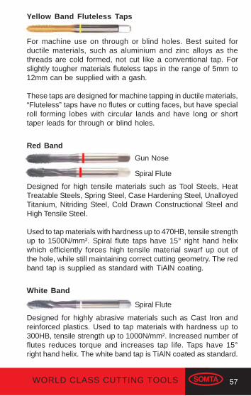
Yellow Band Fluteless Taps
For machine use on through or blind holes. Best suited forductile materials, such as aluminium and zinc alloys as thethreads are cold formed, not cut like a conventional tap. Forslightly tougher materials fluteless taps in the range of 5mm to12mm can be supplied with a gash.
These taps are designed for machine tapping in ductile materials,“Fluteless” taps have no flutes or cutting faces, but have specialroll forming lobes with circular lands and have long or shorttaper leads for through or blind holes.
Red Band
Designed for high tensile materials such as Tool Steels, HeatTreatable Steels, Spring Steel, Case Hardening Steel, UnalloyedTitanium, Nitriding Steel, Cold Drawn Constructional Steel andHigh Tensile Steel.
Used to tap materials with hardness up to 470HB, tensile strengthup to 1500N/mm². Spiral flute taps have 15° right hand helixwhich efficiently forces high tensile material swarf up out ofthe hole, while still maintaining correct cutting geometry. The redband tap is supplied as standard with TiAlN coating.
White Band
Designed for highly abrasive materials such as Cast Iron andreinforced plastics. Used to tap materials with hardness up to300HB, tensile strength up to 1000N/mm². Increased number offlutes reduces torque and increases tap life. Taps have 15°right hand helix. The white band tap is TiAlN coated as standard.
Gun Nose
Spiral Flute
Spiral Flute

58 WORLD CLASS CUTTING TOOLS
Blue Band
Designed for tough materials, such as Stainless Steel, TitaniumAlloys, Cast Steel, Heat Resisting Steel and Work HardeningSteel. Used to tap materials with hardness up to 350HB, tensilestrength up to 1250N/mm².
Truncated thread after lead reduces frictional contact with thethreaded hole and allows easier penetration of coolant. Spiralflute taps have 40° right hand helix allowing tough material swarfto be efficiently removed from the hole. Supplied as standardwith TiAIN coating.
Special taps are available on request.
Spiral Flute
Gun Nose

59WORLD CLASS CUTTING TOOLS
TAP NOMENCLATURE
SIZE OF SQUAREACROSS FLATS
SECTION B-B
BB
FLA
T L
EN
GT
H
AA
n
LEADANGLE
NOMINALDIAMETER
ROOTDIAMETER
TH
RE
AD
LE
NG
TH
CH
AM
FE
R L
EA
D
n = No. OF THREADSPER INCH.
p = PITCH
LAND
FLUTE CUTTINGFACE
WEBTHICKNESS
SECTION A-A
SHANKDIAMETER
p
OV
ER
ALL
LE
NG
TH

60 WORLD CLASS CUTTING TOOLS
Abbreviations for standard thread forms
BSW - British Standard WhitworthBSF - British Standard FineBA - British AssociationBSB - British Standard Brass
General Specifications: ISO 529Threads ground to: BS 949: 1976 CLASS 2
BSP - British Standard Pipe (Fine) "G" SeriesBSPT - British Standard Pipe Taper (Rc Series)
General Specifications: ISO 2284Threads ground to: BS 949: 1976 G-Series
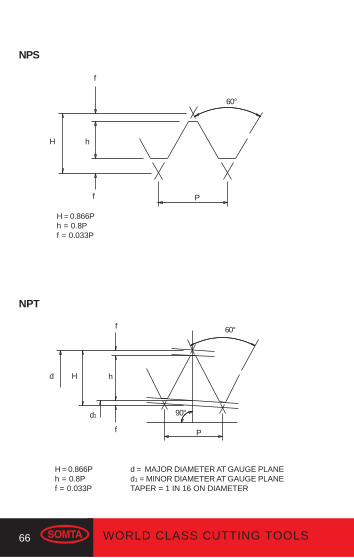
NPS - National Pipe StraightNPT - National Pipe Taper
General Specifications: ANSI 94.9 1979Threads ground to: ANSI 94.9 1979
UNC - Unified National CoarseUNF - Unified National Fine
General Specifications: ISO 529Threads ground to: ANSI B1.1 1982 2B
M - MetricM F - Metric Fine
General Specifications: ISO 529 ISO 2283 (Long Series)Threads ground to: ISO 2857 - 1973, Class 2
General Specifications: DIN 371 / DIN 374 / DIN 376Threads ground to: DIN 802 CLASS 6H
U N E F - Unified Extra Fine
61WORLD CLASS CUTTING TOOLS
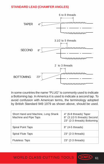
In some countries the name “PLUG” is commonly used to indicatea Bottoming tap. In America it is used to indicate a second tap. Toavoid confusion with American terms, the terminology adoptedby British Standard 949 1979 as shown above, should be used.
STANDARD LEAD (CHAMFER ANGLES)
TAPER
SECOND
BOTTOMING
6 to 8 threads
3.1/2 to 5 threads
2 to 3 threads
4°
8°
23°
Short Hand and Machine, Long Shank 4° (6-8 threads) TaperMachine and Pipe Taps 8° (3.1/2-5 threads) Second
23° (2-3 threads) Bottoming
Spiral Point Taps 8° (4-5 threads)
Spiral Flute Taps 23° (2-3 threads)
Fluteless Taps 23° (2-3 threads)

62 WORLD CLASS CUTTING TOOLS
NUT
MAJOR DIA.
PITCH DIA.
MINOR DIA.
THREADANGLE
HELIX ANGLEAT PITCH DIA.
PITCH
SCREW
THREAD FORMS
COMPONENT ELEMENTS

63WORLD CLASS CUTTING TOOLS
WHITWORTH
H = 0.866Ph = 0.61343Pr = 0.1443P
ISO METRIC
60°
p
H hr
r
55°
p
H = 0.960491Ph = 0.640327Pr = 0.137329P
H h
64 WORLD CLASS CUTTING TOOLS
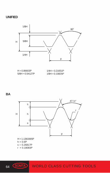
UNIFIED
H = 0.86603P5/8H = 0.54127P
1/4H = 0.21651P1/8H = 0.10825P
BA
H = 1.1363365Ph = 0.6Ps = 0.26817Pr = 0.18083P
1/4H
p
1/8H60°
5/8H
p
s47-½°
H
s
h
r
H

65WORLD CLASS CUTTING TOOLS
H = 0.960237Ph = 0.640327Pr = 0.137278P
BSPT
d = MAJOR DIAMETER AT GAUGE PLANEd1 = MINOR DIAMETER AT GAUGE PLANETAPER = 1 IN 16 ON DIAMETER
BSB
H = 0.86603Ph = 0.5237Pr = 0.1667P
55°
P
90°d1
H hr
d
P
55°
rhH
66 WORLD CLASS CUTTING TOOLS
H = 0.866Ph = 0.8Pf = 0.033P
H = 0.866Ph = 0.8Pf = 0.033P
NPT
d = MAJOR DIAMETER AT GAUGE PLANEd1 = MINOR DIAMETER AT GAUGE PLANETAPER = 1 IN 16 ON DIAMETER
Pf
NPS
f
hH
60°
P
90°d1
f
60°f
H hd
67WORLD CLASS CUTTING TOOLS
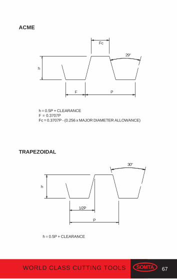
ACME
h = 0.5P + CLEARANCEF = 0.3707PFc = 0.3707P - (0.256 x MAJOR DIAMETER ALLOWANCE)
TRAPEZOIDAL
h = 0.5P + CLEARANCE
Fc
29°
F P
h
30°
h
1/2P
P

68 WORLD CLASS CUTTING TOOLS
RECOMMENDED TAPPING DRILL SIZES
Size0.40.450.50.60.70.750.811
1.251.251.51.51.75
22
2.52.52.533
3.53.53.544
4.54.555
5.5
TappingDrill Size (mm)
*Fluteless Tapping Drill Sizes
M2M2.5M3M3.5M4M4.5M5M6M7M8M9M10M11M12M14M16M18M20M22M24M27M30M32M33M36M39M42M45M48M52M56
1.6 (1.8)*2.05
2.5 (2.75)*2.9 (3.2)*3.3 (3.65)*3.7 (4.1)*4.2 (4.6)*5 (5.5)*
66.8 (7.4)*
7.88.5 (9.25)*
9.510.2 (11.1)*
1214
15.517.519.52124
26.528.529.53235
37.540.54347
50.5
Metric Coarse
Pitch
(For 75% thread depth)

69WORLD CLASS CUTTING TOOLS
Metric FineSize
TappingDrill Size (mm)
MF2MF2.5MF3MF3.5MF4MF4.5MF5MF6MF7MF8MF8MF9MF10MF10MF12MF12MF14MF14MF16MF16MF18MF18MF20MF20MF22MF22MF24MF24MF25MF25MF27MF30MF30MF32MF33MF36
0.250.350.350.350.50.50.5
0.750.750.75
111
1.251.251.5
1.251.51
1.51.52
1.52
1.52
1.52
1.522
1.52
1.51.51.5
1.752.152.653.153.54
4.55.256.257.2789
8.7510.7510.5
12.7512.515
14.516.516
18.518
20.520
22.522
23.52325
28.528
30.531.534.5
Pitch

70 WORLD CLASS CUTTING TOOLS
Metric Fine (cont)
MF36MF39MF40MF42MF45MF48MF50MF52
2.01.51.51.51.51.51.51.5
3437.538.540.543.546.548.550.5
3/321/85/323/167/321/45/163/87/161/29/165/83/47/81"1.1/81.1/41.1/21.3/42"
48403224242018161412121110987765
4.1/2
1.92.553.23.74.55.16.58
9.310.512.213.516.519.5222528343945
SizeTapping
Drill Size (mm)Pitch
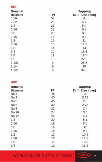
BSWNominalDiameter
TappingDrill Size (mm)TPI
If you have any cutting tool problem, please feel freeto contact our technical sales representatives.
71WORLD CLASS CUTTING TOOLS
3/167/321/45/163/87/161/29/165/83/47/81"1.1/81.1/41.1/2
322826222018161614121110998
44.75.46.88.39.811
12.714
16.519.522.525.529
34.5
No.3No.4No.5No.6No.8No.10No.121/45/163/87/161/29/165/83/4
484040323224242018161413121110
22.252.6
2.753.43.84.45.16.68
9.410.812.213.516.5
BSFNominalDiameter
TappingDrill Size (mm)TPI
UNCNominalDiameter
TappingDrill Size (mm)TPI
72 WORLD CLASS CUTTING TOOLS
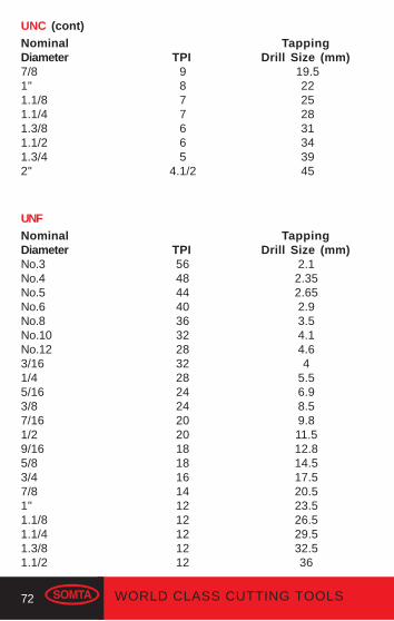
No.3No.4No.5No.6No.8No.10No.123/161/45/163/87/161/29/165/83/47/81"1.1/81.1/41.3/81.1/2
56484440363228322824242020181816141212121212
2.12.352.652.93.54.14.64
5.56.98.59.811.512.814.517.520.523.526.529.532.536
UNC (cont)NominalDiameter
TappingDrill Size (mm)TPI
19.522252831343945
9877665
4.1/2
7/81"1.1/81.1/41.3/81.1/21.3/42"
UNFNominalDiameter
TappingDrill Size (mm)TPI

73WORLD CLASS CUTTING TOOLS
BANominalDiameter
TappingDrill Size (mm)TPI
012345678910
25.428.231.334.838.343.147.952.959.165.172.6
5.14.53.93.43
2.652.3
2.051.8
1.551.4
NPS
NominalDiameter
TappingDrill Size (mm)TPI
1/81/43/81/23/41"1.1/41.1/22"
2718181414
11.1/211.1/211.1/211.1/2
9.112
15.519
24.530.539.445.557.5
1/81/43/81/23/4
2718181414
8.411
14.2517.523
NPTNominalDiameter
TappingDrill Size (mm)TPI
74 WORLD CLASS CUTTING TOOLS
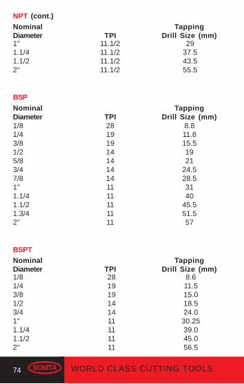
1/81/43/81/25/83/47/81"1.1/41.1/21.3/42"
281919141414141111111111
8.811.815.51921
24.528.53140
45.551.557
BSP
NominalDiameter
TappingDrill Size (mm)TPI
BSPTNominalDiameter
TappingDrill Size (mm)TPI
281919141411111111
8.611.515.018.524.0
30.2539.045.056.5
1/81/43/81/23/41"1.1/41.1/22"
1"1.1/41.1/22"
11.1/211.1/211.1/211.1/2
2937.543.555.5
NPT (cont.)NominalDiameter
TappingDrill Size (mm)TPI

75WORLD CLASS CUTTING TOOLS
FLUTELESS TAPS
Fluteless taps are used for cold forming threads in ductilematerials and have the following advantages.
(a) Increased strength and tap life resulting from:(i) Elimination of flutes which reduce the shear strength
of the tap.(ii) The lack of cutting edges which, in a conventional
tap, wear and break down.(iii) The lack of chips, which sometimes causes jamming.
(b) Better blind hole tapping due to the lack of chips and problemsrelating to chip removal.
(c) Higher productivity due to faster tapping speeds.(d) Stronger threads.
The grain fibres of the metal are not cut, but displaced, to formthe threads, which are stronger than cut threads. It is acceptedthat a 60% cold formed thread is as strong as a 75% cut thread.
STRONGER THREAD
GRAIN FIBRE OFMETAL UNBROKENBURNISHED THREAD
NO CHIPS
76 WORLD CLASS CUTTING TOOLS
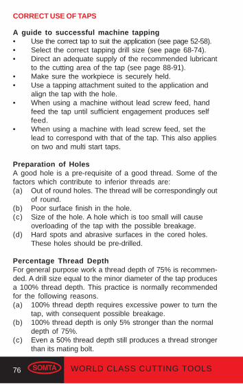
CORRECT USE OF TAPS
A guide to successful machine tapping• Use the correct tap to suit the application (see page 52-58).• Select the correct tapping drill size (see page 68-74).• Direct an adequate supply of the recommended lubricant
to the cutting area of the tap (see page 88-91).• Make sure the workpiece is securely held.• Use a tapping attachment suited to the application and
align the tap with the hole.• When using a machine without lead screw feed, hand
feed the tap until sufficient engagement produces selffeed.
• When using a machine with lead screw feed, set thelead to correspond with that of the tap. This also applieson two and multi start taps.
Preparation of HolesA good hole is a pre-requisite of a good thread. Some of thefactors which contribute to inferior threads are:(a) Out of round holes. The thread will be correspondingly out
of round.(b) Poor surface finish in the hole.(c) Size of the hole. A hole which is too small will cause
overloading of the tap with the possible breakage.(d) Hard spots and abrasive surfaces in the cored holes.
These holes should be pre-drilled.
Percentage Thread DepthFor general purpose work a thread depth of 75% is recommen-ded. A drill size equal to the minor diameter of the tap producesa 100% thread depth. This practice is normally recommendedfor the following reasons.(a) 100% thread depth requires excessive power to turn the
tap, with consequent possible breakage.(b) 100% thread depth is only 5% stronger than the normal
depth of 75%.(c) Even a 50% thread depth still produces a thread stronger
than its mating bolt.

77WORLD CLASS CUTTING TOOLS
1/2PITCH
WIDTH OFFLAT CREST
CRESTRAD.
MIN
OR
DIA
.
EF
FE
CT
IVE
DIA
.
MA
JOR
DIA
.TR
IAN
GU
LAR
HE
IGH
T
NUT
BOLT
CRESTRAD.
BASIC DEPTHOF THREAD
WIDTH OFFLAT ROOT
ROOTRAD.
MIN
OR
DIA
.
EF
FE
CT
IVE
DIA
.
MA
JOR
DIA
.
1/2PITCH
PITCH
Basic sizes and tolerance classes
To allow for clearance between mating internal and externalthreads, taps are manufactured with oversize allowances addedto the basic diameters.These basic diameters plus the oversize allowances establish:
(a) the minimum effective diameter; and
(b) the minimum major diameter.
ROOTRAD.
THREADANGLE
78 WORLD CLASS CUTTING TOOLS
Limits of Tolerance
Effective Diameter - The tolerance is the amount of variationallowed in the manufacture of the tap. This tolerance is addedto the minimum effective diameter to establish the maximumeffective diameter.
It follows that:Basic Effective + Oversize
= Minimum Effective
Basic Effective + Oversize + tolerance= Maximum Effective
The effective diameter can only be measured with special tapmeasuring equipment.
Major Diameter - The minimum major diameter is established byadding the oversize allowance to the basic major diameter (thenominal thread size). Therefore, on measurement, the majordiameter of the tap is larger than the nominal thread size, andmust not be used to judge the size of the tap.
The maximum major diameter of the tap is governed by thethread form and is therefore not subject to a tolerance.
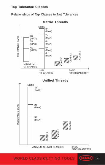
79WORLD CLASS CUTTING TOOLS
Tap Tolerance Classes
Relationships of Tap Classes to Nut Tolerances
Metric Threads
Unified Threads
6G(MAX)5G(MAX)
4G(MAX)
MINIMUM'G' GRADES
NUTS8H(MAX)
7H(MAX)6H(MAX)
5H(MAX)4H(MAX)
MIN.'H' GRADES
BASICPITCH DIAMETER
12345123451234512345
TO
LER
AN
CE
BA
ND
12345123451234512345
1234123412341234
CLA
SS
1
CLA
SS
2
CLA
SS
3
TO
LER
AN
CE
BA
ND
NUTS1B(MAX)
2B(MAX)
3B(MAX)
MINIMUM ALL NUT CLASSES BASICPITCH DIAMETER
1234512345123451234512345
1234512345123451234512345123451234512345
12345123451234512345123451234512345
CLA
SS
1
CLA
SS
2 CLA
SS
3

80 WORLD CLASS CUTTING TOOLS
Class 1 TapThis is closest to basic, having little oversize allowance, and isnormally specified for "close" fit threads, eg. Unified 3B, Metric4H, 5H.
Class 2 TapThis is normally specified for "medium" fit threads, eg. Unified2B, Metric 6H, 4G, 5G.
Class 3 TapThis is futhermost above basic size and used for "free" fitthreads, eg. Unified 1B, Metric 7H, 8H, 6G.
Under favourable working conditions, the following threadtolerances should be produced by the new class taps.
All Somta HSS taps are supplied to Class 2, 6H unless otherwisespecified.
RE-SHARPENING TAPSMaximum productivity and tap life can only be obtained from atap that is kept in good condition and handled with care.
When re-sharpening becomes necessary, regrinding by handis not recommended, though it is probably better than usingchipped or worn taps. The recommended method is to usespecial tap grinding attachments or machines, and to follow theoriginal form of the tap.
MetricUnifiedWhitworth FormBA
Class 14H, 5H3BClose ClassClose Class
Class 26H, 4G, 5G2BMedium ClassMedium Class
Class 37H, 8H, 6G1BFree ClassFree Class

81WORLD CLASS CUTTING TOOLS
TAPPING PROBLEMS: CAUSES AND SOLUTIONS
Damaged tap threads in the hole(a) Possible Cause
Mis-alignment of the tap with the hole before starting to tap.SolutionCare must be taken to align the tap with the hole beforestarting to tap.
(b) Possible CauseThe tap is too dullSolutionUse a tap which is in good condition.
(c) Possible CauseWork hardened skin in the drilled hole.SolutionWork hardening can be avoided when drilling by using thecorrect speeds,and coolants. See page 34-35. Use serialtaps.
(d) Possible CauseIncorrect rake angleSolutionUse the recommended tap for the material. See page 52-58.
Poor finish of the thread(a) Possible Cause
Using the incorrect tap.SolutionUse the recommended tap.
(b) Possible CauseThe drilled hole is too small.SolutionUse the recommended drill size. See page 68-74.
(c) Possible CauseThe tap is too dull.SolutionUse a tap which is good condition.
(d) Possible CauseInsufficient number of threads on the lead.

82 WORLD CLASS CUTTING TOOLS
SolutionUse a tap with the correct lead.
(e) Possible CauseMis-alignment of the tap and the hole.SolutionCare must be taken to align the tap with the hole beforestarting to tap.
(f) Possible CauseIncorrect rake angleSolutionUse the recommended tap for the material. See page 52-58.
Torn threads in the tapped hole(a) Possible Cause
The flutes are clogged by chips.SolutionUse a spiral point or a spiral flute tap.
(b) Possible CauseDistortion of the walls in a thin walled workpiece.SolutionUse a multi-fluted tap.
(c) Possible CauseThe threads on the tap are broken.SolutionUse a tap which is in good condition.
(d) Possible CauseLack of/or the wrong type of lubricant.SolutionApply an adequate supply and the correct type of lubricantto the cutting area. See page 88-91.
(e) Possible CauseUsing the incorrect or unsuitable tap for the material.SolutionUse the recommended tap for the material. See page 52-58.
(f) Possible CauseTap hitting the bottom of the hole.SolutionAllow sufficient clearance at the bottom of the hole.

83WORLD CLASS CUTTING TOOLS
(g) Possible CauseIncorrect rake angle.SolutionUse the recommended tap for the material. See page 52-58.
Excessive Tap Wear(a) Possible Cause
Mis-alignment of the tap and the hole.SolutionCare must be taken to align the tap with the hole beforestarting to tap.
(b) Possible CauseLack of/or the wrong type of lubricant.SolutionApply an adequate supply and the correct type of lubricantto the cutting area.
(c) Possible CauseThe material is abrasive.Solution(i) Use the correct type of tap.(ii) Use a surface treated tap.
(d) Possible CauseUsing the incorrect tap.Solution(i) Use a tap with the correct lead.(ii) Use a surface treated tap.
(e) Possible CauseIncorrect rake angleSolutionUse the recommended tap for the material. See page 52-58.
Over-Heating of tap(a) Possible Cause
Lack of/or the wrong type of lubricant.SolutionApply an adequate supply and the correct type of lubricantto the cutting area.
(b) Possible Cause
84 WORLD CLASS CUTTING TOOLS
The tap is too dull.SolutionUse a tap which is in a good condition.
(c) Possible CauseThe wrong type of tap is used.SolutionUse the recommended tap. See page 52-58.
(d) Possible CauseExcessive tapping speed is applied.SolutionUse the recommended tapping speed. See page 88-91.
Bell-Mouthed Tapped Hole(a) Possible Cause
Mis-alignment of the tap and the hole.SolutionCare must be taken to align the tap with the hole beforestarting to tap.
(b) Possible CauseThe workpiece is not rigidly held.SolutionSecure the workpiece
(c) Possible CauseExcessive pressure is applied when starting to tap.SolutionOnly sufficient pressure to initiate self-feeding should beapplied.
(d) Possible CauseInsufficient number of threads on the lead.SolutionUse a tap with a longer lead.
(e) Possible CauseThe drilled hole is too small.SolutionUse the recommended drill size. See page 68-74.
Over-size tapped hole(a) Possible Cause
85WORLD CLASS CUTTING TOOLS
Using the incorrect tap.SolutionUse the recommended tap. See page 52-58.
(b) Possible CauseMis-alignment of the tap and the hole.SolutionCare must be taken to align the tap with the hole beforestarting to tap.
(c) Possible CauseLack of/or wrong type of lubricant.SolutionApply an adequate supply and the correct type of lubricant
to the cutting area.(d) Possible Cause
Incorrect rake angle.SolutionUse the recommended tap for the material. See page 52-58.
Tap binding in the hole(a) Possible Cause
Using the incorrect tap.SolutionUse the recommended tap.See page 52-58.
(b) Possible CauseThe drilled hole is too small.SolutionUse the recommended drill size. See page 68-74.
(c) Possible CauseLack of/or the wrong type of lubricant.SolutionApply an adequate supply and the correct type of lubricantto the cutting area. See page 88-91.
(d) Possible CauseThe flutes are clogged with chips.SolutionUse a spiral point or a spiral flute tap.
(e) Possible CauseIncorrect rake angle.

86 WORLD CLASS CUTTING TOOLS
SolutionUse the recommended tap for the material. See page 52-58.
Flutes clogged with chips(a) Possible Cause
Using the incorrect tap.SolutionUse a spiral point or spiral flute tap.
(b) Possible CauseLack of/or the wrong type of lubricant.SolutionApply an adequate supply and the correct type of lubricantto the cutting area.
Tap Breakage(a) Possible Cause
Using the incorrect tap.SolutionUse the recommended tap. See page 52-58.
(b) Possible CauseThe tap is too dull.SolutionUse a tap which is in good condition.
(c) Possible CauseThe drilled hole is too small.SolutionUse the recommended tapping drill size. See page 68-74.
(d) Possible CauseThe drilled hole is too shallow.SolutionAllow clearance at the bottom of the hole when drilling.
(e) Possible CauseMis-alignment of the tap and the hole.SolutionCare must be taken to align the tap with the hole beforestarting to tap.
(f) Possible CauseThe flutes are clogged with chips.
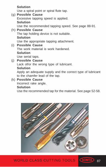
87WORLD CLASS CUTTING TOOLS
SolutionUse a spiral point or spiral flute tap.
(g) Possible CauseExcessive tapping speed is applied.SolutionUse the recommended tapping speed. See page 88-91.
(h) Possible CauseThe tap holding device is not suitable.SolutionUse the appropriate tapping attachment.
(i) Possible CauseThe work material is work hardened.SolutionUse serial taps.
(j) Possible CauseLack of/or the wrong type of lubricant.SolutionApply an adequate supply and the correct type of lubricantto the chamfer lead of the tap.
(k) Possible CauseIncorrect rake angle.SolutionUse the recommended tap for the material. See page 52-58.

88 WORLD CLASS CUTTING TOOLS
TYPE GRADE
CARBONSTEEL
FREE CUTTING
0.3 to 0.4% Carbon
0.3 to 0.4% Carbon
0.4 to 0.7% Carbon
0.4 to 0.7% Carbon
HARDNESS
BRINELL
TONS PER
SQ IN.N/mm²
ALLOYSTEEL
150
170
248
206
286
33
38
54
44
63
500
570
800
650
950
248
330
380
54
74
82
810
1100
1250
STAINLESSSTEEL
Martensitic Free CuttingMartensitic Std. GradeAustenitic Free CuttingAustenitic Std. Grade
TYPICAL PHYSICALPROPERTIES
As Supplied
248 54 810
TITANIUM
Titanium Comm: Pure
Titanium Comm: Pure
Titanium Comm: Pure
Titanium Alloyed
Titanium Alloyed
NIMONICALLOYS
Wrought
Cast
300
350
67
78
1000
1170
170
200
275
340
380
38
43
65
76
85
570
650
975
1140
1275
TOOL STEEL
HSS Standard
Grades
HSS Cobalt Grades
Hot Working Steel
Cold Working Steel
225
225
48
54
720
810
MANGANESESTEEL
As Supplied
Tough
Hard
TAP TECHNICAL DATA

89WORLD CLASS CUTTING TOOLS
*TAPPERIPHERAL
SPEEDm/min
THROUGHHOLE
RECOMMENDEDTAP TYPE
BLINDHOLE
ALTERNATIVETAP TYPE
THROUGHHOLE
BLINDHOLE
LUBRICANTS
Sp/Point Sp/Flute Str/Flute Str/Flute
8-10
8-12
10-15
Sulphur
based oil
Sp/Point Sp/Flute Str/Flute Str/Flute 8-12Sulphur
based oil
Sp/Point Sp/Flute Str/Flute Str/Flute 2-6
Heavy duty
Sulphur
based oil
See CBA Tap section pages 92-93. 2-4Chlorinated
oil
2-4Chlorinated
oil
Sp/Point Sp/Flute Str/Flute Str/Flute 8-10Sulphur
based oil
Sp/Point Str/Flute Str/Flute - 15-20Sulphur
based oil
TAP TECHNICAL DATA (cont.)
See CBA Tap section pages 92-93.
* Tapping speeds for fluteless taps are 2-3 times higher than the recommended speeds given.
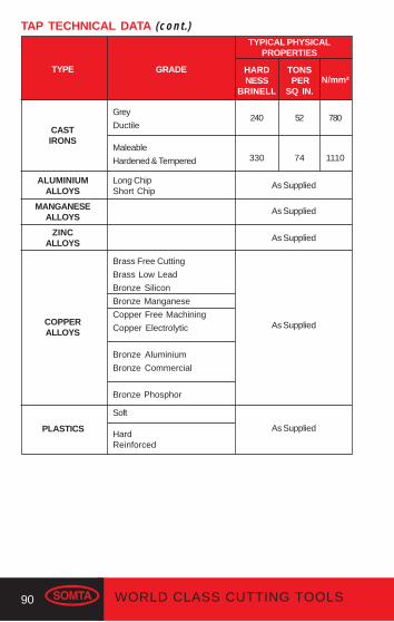
90 WORLD CLASS CUTTING TOOLS
TYPE GRADE HARDNESS
BRINELL
TONS PER
SQ IN.N/mm²
ALUMINIUMALLOYS
240
330
52
74
780
1110
COPPERALLOYS
Brass Free Cutting
Brass Low Lead
Bronze Silicon
Bronze Manganese
Copper Free Machining
Copper Electrolytic
Bronze Aluminium
Bronze Commercial
Bronze Phosphor
TYPICAL PHYSICALPROPERTIES
As Supplied
PLASTICS
TAP TECHNICAL DATA (cont.)
CASTIRONS
Grey
Ductile
Maleable
Hardened & Tempered
Long ChipShort Chip
As Supplied
MANGANESEALLOYS
As Supplied
ZINCALLOYS
As Supplied
Soft
HardReinforced
As Supplied
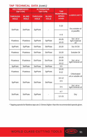
91WORLD CLASS CUTTING TOOLS
*TAPPERIPHERAL
SPEEDm/min
THROUGHHOLE
RECOMMENDEDTAP TYPE
* Tapping speeds for fluteless taps are 2-3 times higher than the recommended speeds given.
BLINDHOLE
ALTERNATIVETAP TYPE
THROUGHHOLE
BLINDHOLE
LUBRICANTS
Str/Flute Str/Flute Sp/Point -
4 -8
5-10
Dry soluble oilor paraffin
Fluteless Fluteless Sp/Point Sp/Flute20-25
10-15
Sol. oil orlight material
oil
Sol. oil orlight mineral oil
Chlorinatedoil or soluble oil
Sp/Point Sp/Flute Str/Flute Str/Flute 15-20 Sul. B Oil
Fluteless Fluteless Str/Flute Str/Flute 15-20 Soluble Oil
Fluteless
Sp/Point
Fluteless
Sp/Point
Fluteless
Str/Flute
Fluteless
Str/Flute
Str/Flute
Str/Flute
Sp/Point
Str/Flute
Str/Flute
Str/Flute
Sp/Point
Str/Flute
15-20
25-30
10-12
3-5
15-20
8-12
10-12
3-5
3-5Sol. oil or
light mineral oil
Str/Flute Str/Flute Sp/Point - Dry4-7
12-15
TAP TECHNICAL DATA (cont.)

92 WORLD CLASS CUTTING TOOLS
CBA TAP TECHNICAL DATA
MATERIAL TYPES HARDNESSHB
TENSILESTRENGTH
N/mm²
Ste
elS
tain
less
Ste
elC
ast I
ron
Tita
nium
Nic
kel
Cop
per
Alu
min
ium
Mag
nesi
umS
ynth
etic
Mat
eria
ls
120
200
250
250
250350
350
250
250
300
150
150300
200
200300
200
270
270350
150
270
270350
100
200
200
470
100
150
120
120
400
700
850
850
8501200
1200
850
850
1000
500
5001000
700
7001000
700
900
9001200
500
900
9001200
350
700
700
1500
350
500
400
400
-
-
-
Surface Treatment (Coating) TiN, TiCN, TiAIN coatings are available on request
Free Cutting steels
Structural steel. Case carburizing steel
Plain carbon steel
Alloy steel
Alloy steel.Hardened and tempered steel
Alloy steel. Hardened and tempered steel
Free machining Stainless steel
Austenit ic
Ferritic + Austenitic, Ferritic, Martensitic
Lamellar graphite
Lamellar graphite
Nodular graphite, Malleable Cast Iron
Nodular graphiteMalleable Cast Iron
Titanium, unalloyed
Titanium, alloyed
Titanium alloyed
Nickel, unalloyed
Nickel, alloyed
Nickel, alloyed
Copper
Beta Brass, Bronze
Alpha Brass
High strength Bronze
Al, Mg, unalloyed
Al alloyed Si < 0.5%
Al alloyed, Si > 0.5%< 10%
Al alloyed, Si > 10%Al-alloys, Mg-alloys
Thermoplastics
Thermosetting plastics
Reinforced plastic materials
-
-
-
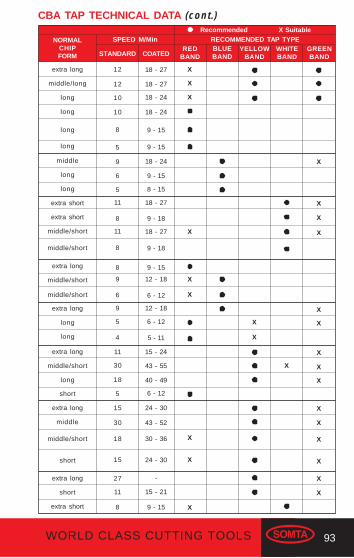
93WORLD CLASS CUTTING TOOLS
RECOMMENDED TAP TYPE
CBA TAP TECHNICAL DATA (cont.)
NORMALCHIPFORM
Recommended X SuitableSPEED M/Min
STANDARD COATEDWHITEBAND
YELLOWBAND
BLUEBAND
REDBAND
extra long
middle/long
long
long
long
middle
long
long
extra short
extra short
middle/short
extra long
middle/short
12
12
10
10
8
5
9
6
5
11
8
11
8
8
9
6
9
18 - 27
18 - 27
18 - 24
18 - 24
9 - 15
9 - 15
18 - 24
9 - 15
8 - 15
18 - 27
9 - 18
18 - 27
9 - 18
9 - 15
12 - 18
6 - 12
12 - 18
5
4
11
30
18
5
15
6 - 12
5 - 11
15 - 24
43 - 55
40 - 49
6 - 12
24 - 30
30
18
15
27
11
8
43 - 52
30 - 36
24 - 30
-
15 - 21
9 - 15
X
X
X
X
X
X
X
X
X
X
X
X
long
middle/short
middle/short
extra long
long
long
extra long
middle/short
long
short
extra long
middle
middle/short
short
extra long
short
extra short
GREENBAND
X
X
X
X
X
X
X
X
X
X
X
X
X
X
X
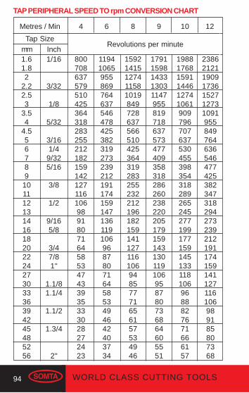
94 WORLD CLASS CUTTING TOOLS
2386212119091736152712731091955849764636546477425382347318294273239212191174159141127116106989185807368
Metres / Min 4 6 8 9 10 12
Tap Sizemm Inch1.61.82
2.22.53
3.54
4.556789
1011121314161820222427303336394245485256
1/16
3/32
1/8
5/32
3/161/4
9/325/16
3/8
1/2
9/165/8
3/47/81"
1.1/81.1/4
1.1/2
1.3/4
2"
8007086375795104253643182832552121821591421271161069891807164585347433935333028272423
1194106595586976463754647842538231927323921219117415914713611910696878071645853494642403734
1592141512741158101984972863756651042536431928325523221219618215914112711610694857771656157534946
17911598143313031147955819718637573477409358318286260238220205179159143130119106958780736864605551
1988176815911446127410619097967076375304553983543182892652452771991771591451331181069688827671666157
Revolutions per minute
TAP PERIPHERAL SPEED TO rpm CONVERSION CHART
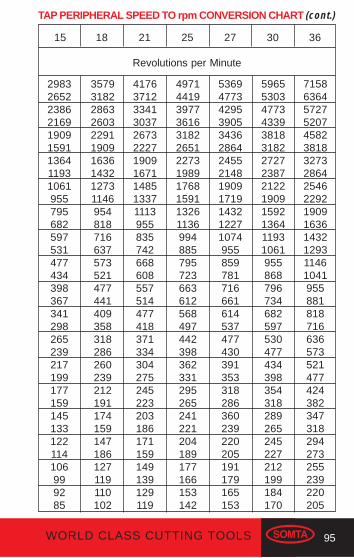
95WORLD CLASS CUTTING TOOLS
15 18 21 25 27 30 36
298326522386216919091591136411931061955795682597531477434398367341298265239217199177159145133122114106999285
3579318228632603229119091636143212731146954818716637573521477441409358318286260239212191174159147186127119110102
41763712334130372673222719091671148513371113955835742668608557514477418371334304275245223203186171159149139129119
497144193977361631822651227319891768159113261136994885795723663612568497442398362331295265241221204189177166153142
5369477342953905343628642455214819091719143212271074955859781716661614537477430391353318286360239220205191179165153
59655303477343393818318227272387212219091592136411931061955868796734682597530477434398354318289265245227212199184170
7158636457275207458238183273286425462292190916361432129311461041955881818716636573521477424382347318294273255239220205
Revolutions per Minute
TAP PERIPHERAL SPEED TO rpm CONVERSION CHART (cont.)

96 WORLD CLASS CUTTING TOOLS
CUTTERS
SHANK CUTTERS
Selecting the correct Shank Cutter
Two and Three Flute End Mills
Two and three flute end mills are shank type cutters withperipheral teeth and end teeth of the plunging type. Intended forgeneral purpose use, they have right hand cutting, right handhelical teeth; they are used on keyway and closed slottingoperations where the close minus tolerance of the cuttingdiameter allows slot widths to be produced in one pass.
These cutters are also extensively used when profiling andend milling aluminium alloys, due to the greater chip spacerequired by this material.
Two Flute Ball Nose End Mills
Ball nosed two flute end mills are manufactured to the sametolerances as the normal two flute end mill, and have a centrecutting ball end. They are used extensively in die making forcutting fillets, radiused slots, pocketing etc. These cutters haveright hand cutting, right hand helical teeth.
Cutting tools may shattereye protection should be worn

97WORLD CLASS CUTTING TOOLS
Multi-Flute End Mills
Multi-flute end mills are shank type cutters with peripheral teethand end teeth of the both plunging and non-plunging type.
Designed for general purpose use they have right hand cutting,right hand helical teeth, and are used in stepping and profilingapplications. They can also be used on slots where the plustolerance of the cutting diameter is not critical.
Roughing End Mills
Shank type cutters with right hand cutting, right hand helicalteeth on the periphery with roughing profile and with heavyduty end teeth.
These cutters are robust and durable even under heavy cuttingconditions on a wide range of materials. They are intended forrapid and heavy rates of stock removal where surface finish isof lesser importance. Available in coarse and fine pitch knuckleform and flat crest type.
Corner Rounding Cutters
Straight tooth cutters with right hand cutting teeth. Intended toproduce a true convex up to 90° of arc.

98 WORLD CLASS CUTTING TOOLS
Woodruff Cutters
Shank type cutters with right hand cutting alternate helicalperipheral teeth. Available in a range of diameters and widths.Designed to produce slots to suit standard woodruff keys.
T-Slot Cutters
Shank type cutters with right hand cutting alternate helicalperipheral teeth as well as teeth on either face. Intended foropening out existing slots to form the T-slots used extensivelyon machine tables. They are produced in a range of diametersand widths to allow clearance on a standard range of bolt headsizes.
Dovetail Cutters
These angle cutters have right hand cutting straight teeth andnon-plunging end teeth. They are used wherever dovetails orangles are required and are available in a range of angles anddiameters.
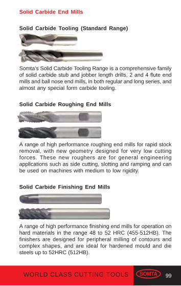
99WORLD CLASS CUTTING TOOLS
Solid Carbide End Mills
Solid Carbide Tooling (Standard Range)
Somta’s Solid Carbide Tooling Range is a comprehensive familyof solid carbide stub and jobber length drills, 2 and 4 flute endmills and ball nose end mills, in both regular and long series, andalmost any special form carbide tooling.
Solid Carbide Roughing End Mills
A range of high performance roughing end mills for rapid stockremoval, with new geometry designed for very low cuttingforces. These new roughers are for general engineeringapplications such as side cutting, slotting and ramping and canbe used on machines with medium to low rigidity.
Solid Carbide Finishing End Mills
A range of high performance finishing end mills for operation onhard materials in the range 48 to 52 HRC (455-512HB). Thefinishers are designed for peripheral milling of contours andcomplex shapes, and are ideal for hardened mould and diesteels up to 52HRC (512HB).
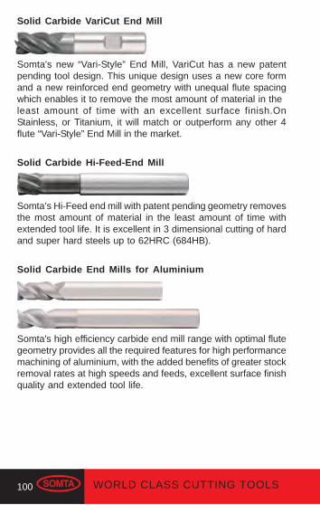
100 WORLD CLASS CUTTING TOOLS
Solid Carbide VariCut End Mill
Somta's new “Vari-Style” End Mill, VariCut has a new patentpending tool design. This unique design uses a new core formand a new reinforced end geometry with unequal flute spacingwhich enables it to remove the most amount of material in theleast amount of time with an excellent surface finish.OnStainless, or Titanium, it will match or outperform any other 4flute “Vari-Style” End Mill in the market.
Solid Carbide Hi-Feed-End Mill
Somta’s Hi-Feed end mill with patent pending geometry removesthe most amount of material in the least amount of time withextended tool life. It is excellent in 3 dimensional cutting of hardand super hard steels up to 62HRC (684HB).
Solid Carbide End Mills for Aluminium
Somta's high efficiency carbide end mill range with optimal flutegeometry provides all the required features for high performancemachining of aluminium, with the added benefits of greater stockremoval rates at high speeds and feeds, excellent surface finishquality and extended tool life.
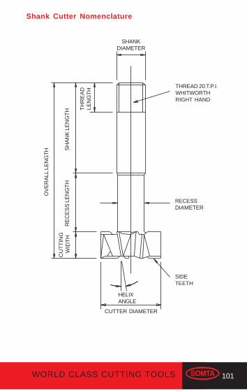
101WORLD CLASS CUTTING TOOLS
Shank Cutter Nomenclature
SHANKDIAMETER
THREAD 20 T.P.I.WHITWORTHRIGHT HAND
RECESSDIAMETER
SIDETEETH
HELIXANGLE
CUTTER DIAMETER
CU
TT
ING
WID
TH
RE
CE
SS
LE
NG
TH
SH
AN
K L
EN
GT
H
OV
ER
ALL
LE
NG
TH
TH
RE
AD
LEN
GT
H
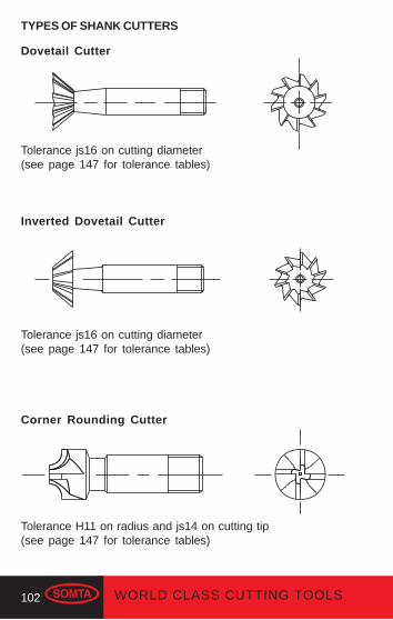
102 WORLD CLASS CUTTING TOOLS
Dovetail Cutter
Tolerance js16 on cutting diameter(see page 147 for tolerance tables)
Inverted Dovetail Cutter
Tolerance js16 on cutting diameter(see page 147 for tolerance tables)
Corner Rounding Cutter
Tolerance H11 on radius and js14 on cutting tip(see page 147 for tolerance tables)
TYPES OF SHANK CUTTERS
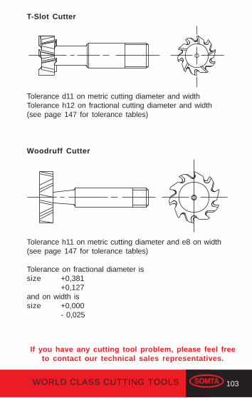
103WORLD CLASS CUTTING TOOLS
T-Slot Cutter
Tolerance d11 on metric cutting diameter and widthTolerance h12 on fractional cutting diameter and width(see page 147 for tolerance tables)
Woodruff Cutter
Tolerance h11 on metric cutting diameter and e8 on width(see page 147 for tolerance tables)
Tolerance on fractional diameter issize +0,381
+0,127and on width issize +0,000
- 0,025
If you have any cutting tool problem, please feel freeto contact our technical sales representatives.
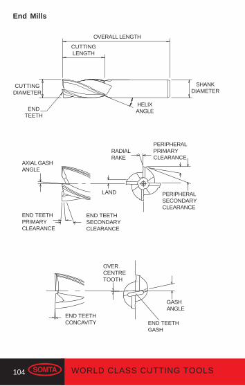
104 WORLD CLASS CUTTING TOOLS
OVERALL LENGTH
CUTTINGLENGTH
CUTTINGDIAMETER
SHANKDIAMETER
ENDTEETH
HELIXANGLE
End Mills
AXIAL GASHANGLE
END TEETHPRIMARYCLEARANCE
END TEETHSECONDARYCLEARANCE
LAND
RADIALRAKE
PERIPHERALPRIMARYCLEARANCE
PERIPHERALSECONDARYCLEARANCE
END TEETHCONCAVITY
OVERCENTRETOOTH
GASHANGLE
END TEETHGASH
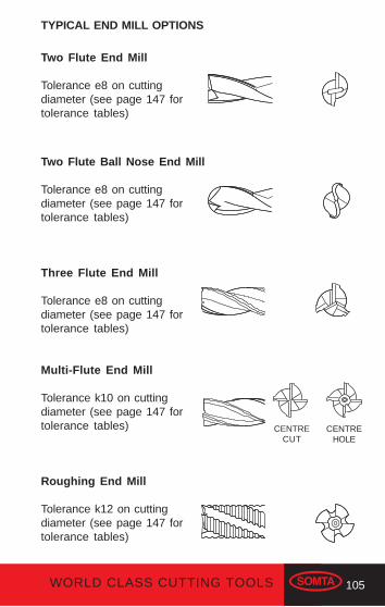
105WORLD CLASS CUTTING TOOLS
Two Flute End Mill
Tolerance e8 on cuttingdiameter (see page 147 fortolerance tables)
Two Flute Ball Nose End Mill
Tolerance e8 on cuttingdiameter (see page 147 fortolerance tables)
Three Flute End Mill
Tolerance e8 on cuttingdiameter (see page 147 fortolerance tables)
Multi-Flute End Mill
Tolerance k10 on cuttingdiameter (see page 147 fortolerance tables)
Roughing End Mill
Tolerance k12 on cuttingdiameter (see page 147 fortolerance tables)
TYPICAL END MILL OPTIONS
CENTRECUT
CENTREHOLE
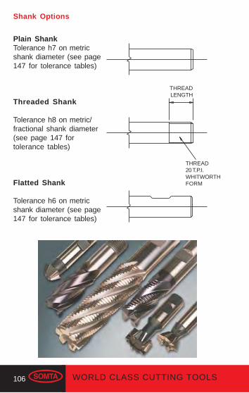
106 WORLD CLASS CUTTING TOOLS
Shank Options
Plain ShankTolerance h7 on metricshank diameter (see page147 for tolerance tables)
Threaded Shank
Tolerance h8 on metric/fractional shank diameter(see page 147 fortolerance tables)
Flatted Shank
Tolerance h6 on metricshank diameter (see page147 for tolerance tables)
THREADLENGTH
THREAD20 T.P.I.WHITWORTHFORM

107WORLD CLASS CUTTING TOOLS
Hints for successful Shank Cutter usage
It is assumed that the workpiece clamping and machine sizeand power are adequate for the intended operation. Alwaysselect the most suitable tool for the job on hand; a few minutesspent on selection can save hours of machining. Use roughingend mills when removing large amounts of stock; two or threeflute end mills for deep slotting applications, for edge cuttingand espically when machining light alloys. Use multi-flute endmills for edge cutting as well as for light finishing cuts.
Use threaded shank or flatted shank cutters where heavy stockremoval and high tooth loads are involved. Plain shank cuttersare particularly suitable for quick change CNC applications andfor pre-setting off the machine.
Where possible check workpiece condition and hardness. Checkchucks and collets regularly ensuring that they are in goodcondition. The most likely cause of cutter run-out is damagedchucks and collets. Always clean cutter shanks and colletsprior to assembly. Check that cutters are running true. Maintaincutters in a sharp condition to ensure maximum stock removal,surface finish and maximum power requirement.
Re-sharpen immediately when signs of wear are visible, sinceregrinding is then a relatively quick operation requiring little stockremoval and with resulting increase in tool life. (See page 125for resharpening details). Cutter storage is of paramountimportance due to the brittle nature of the hardened cuttingedges of all cutting tools. Poor storage often causes damagesuch as chipping of the cutting edges and breakage of corners,resulting in a tool which is useless. As in all machining operationscleaniless is essential.
The best machining results are produced by cutters operatingat the correct speed and feed to suit the material being worked.(See page 134-137 for technical data.)
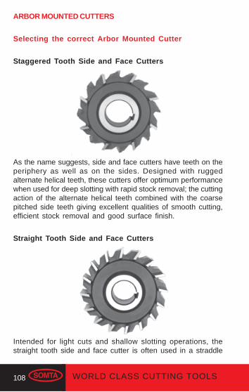
108 WORLD CLASS CUTTING TOOLS
ARBOR MOUNTED CUTTERS
Selecting the correct Arbor Mounted Cutter
Staggered Tooth Side and Face Cutters
As the name suggests, side and face cutters have teeth on theperiphery as well as on the sides. Designed with ruggedalternate helical teeth, these cutters offer optimum performancewhen used for deep slotting with rapid stock removal; the cuttingaction of the alternate helical teeth combined with the coarsepitched side teeth giving excellent qualities of smooth cutting,efficient stock removal and good surface finish.
Straight Tooth Side and Face Cutters
Intended for light cuts and shallow slotting operations, thestraight tooth side and face cutter is often used in a straddle

109WORLD CLASS CUTTING TOOLS
Cylindrical Cutters
Intended for medium/light surfacing cuts these helical cuttersoffer the benefits of shock reduction combined with a goodcutting action.
Angle Cutters
Produced with light duty straight teeth these cutters are usedmainly for cutting dovetails, serrations and angled slots on lessdifficult materials.
milling function where two parallel surfaces are machinedsimultaneously. It is considered to be a compromise tool due tothe reduced cutting action of its straight teeth, which causegreater shock when meeting the workpiece than cutters withhelical teeth.
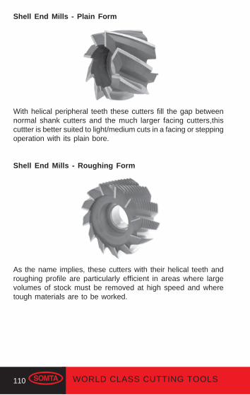
110 WORLD CLASS CUTTING TOOLS
Shell End Mills - Plain Form
With helical peripheral teeth these cutters fill the gap betweennormal shank cutters and the much larger facing cutters,thiscuttter is better suited to light/medium cuts in a facing or steppingoperation with its plain bore.
Shell End Mills - Roughing Form
As the name implies, these cutters with their helical teeth androughing profile are particularly efficient in areas where largevolumes of stock must be removed at high speed and wheretough materials are to be worked.
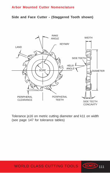
111WORLD CLASS CUTTING TOOLS
Arbor Mounted Cutter Nomenclature
Side and Face Cutter - (Staggered Tooth shown)
Tolerance js16 on metric cutting diameter and k11 on width(see page 147 for tolerance tables)
LAND
RAKEANGLE WIDTH
KEYWAY
PERIPHERALCLEARANCE
PERIPHERALTEETH
SIDE TEETH
HELIXANGLE
DIAMETER
SIDE TEETHCONCAVITY
BORE

112 WORLD CLASS CUTTING TOOLS
OVERALLLENGTH
RAKEANGLE
HELIXANGLE
INTERNALDIAMETER
DIA
ME
TE
RShell End Mills - Plain Form
See page 110 for application.
Shell End Mills - Roughing Form
See page 110 for application.

113WORLD CLASS CUTTING TOOLS
Side and Face Cutter - Straight Tooth
Tolerance js16 on metric/fractional cutting diameter and k11 onmetric/fractional width(see page 147 for tolerance tables)
Cylindrical Cutter
Tolerance js16 on cutting diameter and width(see page 147 for tolerance tables)
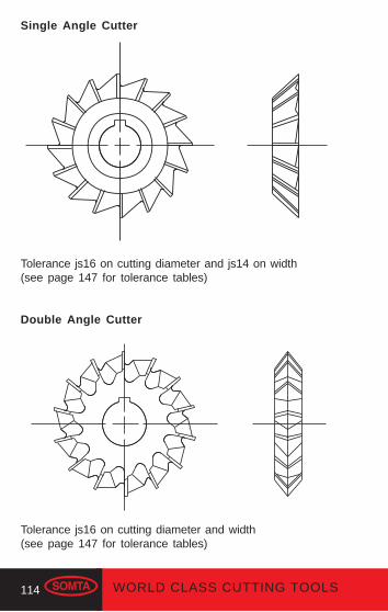
114 WORLD CLASS CUTTING TOOLS
Single Angle Cutter
Tolerance js16 on cutting diameter and js14 on width(see page 147 for tolerance tables)
Double Angle Cutter
Tolerance js16 on cutting diameter and width(see page 147 for tolerance tables)
115WORLD CLASS CUTTING TOOLS
Hints for successful Arbor Mounted Cutter Usage
Some of the many factors governing efficient use of bore cuttersare:-
1) Condition of machine2) Machine power available3) Machine capacity4) Nature of the workpiece
Attention should be given to these factors prior to commence-ment. When using arbor mounted cutters the following pointsshould be observed:-
Taper drive of arbor should be in good condition and fit correctlyinto machine drive.
Arbor and bushes should be kept in good and clean condition;dirty bushes cause run-out of cutters.
Arbors should be oiled and carefully stored when not in use;bent arbors are useless and expensive to replace.
Cutters should run true to prevent overloading of one or twoteeth and extensive regrinding later.
Fit the cutter as closely as possible to the machine column witha support as near to the cutter as the workpiece will allow.
Running bushes and support bearings should be kept clean andin good running condition, particularly with regard to the bushfaces. Lack of support will cause damage to the cutter and theworkpiece. Always use correct lubricants.
Workpiece clamping should be rigid and able to withstand theforces acting upon it under the action of the cutter.

116 WORLD CLASS CUTTING TOOLS
Select correct speeds and feeds for the cutter in use and thenature of the workpiece material and the size of the cut to betaken.
Use recommended coolants and direct flow to the point ofcutting. Consult the coolant suppliers for specific recommen-dations. Adequate cooling is essential to prevent overheating ofthe cutter and failures associated with overheating.
Always use drive keys between the cutter and the arbor; frictionbetween the cutter and the arbor bushes is seldom sufficientwhen cutters are under correct load.
Never force a cutter onto a arbor or over an ill-fitted key. Protectyour hands by wrapping the cutter in a soft material whenfitting or removing it from the arbor.
Due to the brittle nature of hardened tool steels it is not advisableto “remove” a cutter with a mallet once it has been tightenedonto the arbor.
Maintain cutters in sharp condition. Regrind as soon as wearbecomes apparent.
Store cutters carefully when not in use, using a light film of oil toprevent rusting.
Cleanliness of cutters and arbors is essential.
Use helically fluted cutters wherever possible to minimise shockas teeth contact the workpiece.
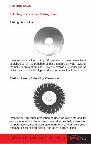
117WORLD CLASS CUTTING TOOLS
SLITTING SAWS
Selecting the correct Slitting Saw
Slitting Saw - Plain
Intended for shallow cutting-off operations, these saws havestraight teeth on the periphery and are tapered on width towardsthe bore to prevent binding. They are available in either coarseor fine pitch to suit the type and section of materials to be cut.
Slitting Saws - Side Chip Clearance
Intended for optimum production of deep narrow slots and forsawing operations, these saws have alternate helical teeth onthe periphery combined with side teeth to ensure efficient stockremoval, clean cutting action, and good surface finish.
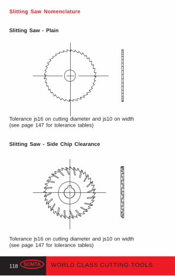
118 WORLD CLASS CUTTING TOOLS
Slitting Saw Nomenclature
Slitting Saw - Plain
Tolerance js16 on cutting diameter and js10 on width(see page 147 for tolerance tables)
Slitting Saw - Side Chip Clearance
Tolerance js16 on cutting diameter and js10 on width(see page 147 for tolerance tables)

119WORLD CLASS CUTTING TOOLS
± 2 times depth of cut
Hints for successful Slitting Saw usage
It is recommended that side plates be used with slitting saws.
120 WORLD CLASS CUTTING TOOLS
CLIMB OR CONVENTIONAL MILLING
From the very beginning of the milling process, it was foundpractical to always rotate the end mill in the opposite direction tothe feed of the workpiece. This is termed conventional milling.
In conventional milling the end mill engages the workpiece at thebottom of the cut. The end mill teeth slide along until sufficientpressure builds up to break through the surface of the work.This sliding action under pressure tends to abrade the periph-ery of the end mill with resulting dulling.
Also in horizontal conventional milling, the cutting action has atendency to lift the workpiece, fixture and table from their bear-ings. In recent years, milling machines have been greatly im-proved through backlash elimination and greater rigidity so thatclimb milling is now possible. Climb milling improves surfacefinish and increases tool life.
In climb milling the end mill rotates in the direction of the feed.The tooth meets the work at the top of the cut at the thickestportion of the chip. This provides instant engagement of the endmill with the workpiece producing a chip of definite thickness atthe start of the cut without the rubbing action resulting fromconventional milling. It further permits the gradual disengage-ment of the teeth and work so that feed marks are largelyeliminated.
Climb milling will often provide better product finish, permit greaterfeed per tooth and prolong the cutter life per sharpening. It isparticularly desirable to climb mill such materials as heat treatedalloy steels and non-free machining grades of stainless steelfor better tool life and to reduce work hardening. It is not recom-mended on material having a hard scale, such as cast or scalyforged surfaces, because abrasion would quickly ruin the cut-ting edges. Also some very soft steels do not lend themselvesto climb milling because of their tendency to drag and tear.
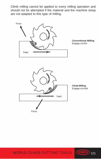
121WORLD CLASS CUTTING TOOLS
Climb milling cannot be applied to every milling operation andshould not be attempted if the material and the machine setupare not adapted to this type of milling.
Conventional MillingEngage cut thin
Climb MillingEngage cut thick
Feed
Feed
Force
Force

122 WORLD CLASS CUTTING TOOLS
PROBLEM SOLVING
Milling problems are often caused by one or more of the follow-ing factors, which should be carefully checked in a systematicand logical manner.
Speeds and FeedsSee page 134-137 for recommendations.
CoolantsSeek advice from your supplier.
Cutter SelectionAlways select the correct type and quality of cutter to suit theapplication.
ArborsStraightness/runout/size/wear/damageBushing-wear/damage.
Re-sharpeningClearance angles. See page 125.RunoutBurning/overheatingSurface finish
Milling MachinesSlides and gib stripsLead screws and nutsBacklash eliminationAttachmentsDefective workheadsWorn tailstocksWorn centres
If you have any cutting tool problem, please feel freeto contact our technical sales representatives.

123WORLD CLASS CUTTING TOOLS
WorkholdingWorkholder conditionWorkholder suitabilityWorkholder alignmentWorkholder rigidity
Workpiece ConditionMachine suitabilityMaterial specificationsMaterial hardnessMaterial surface conditionsMachining characteristics
Cutter HoldersColletsChucksDraw barsRunoutDamage
124 WORLD CLASS CUTTING TOOLS
DIFFICULT TO MACHINE MATERIALS
There are number of materials which are generally regarded asbeing difficult to machine. In general terms the material beingworked is considered to be difficult when it does not respondreadily to normal machining techniques. Among these “difficult’materials are aluminium alloys, stainless steel and work hard-ening steels.
Aluminium Alloys require relatively high speeds and feeds.They respond best to cutters with few teeth and correspond-ingly wide chip spaces, and can be worked very effectivelyby using two flute end mills, which have the advantage offewer teeth engaged in the cut. In many cases coolant maynot be needed to cool the cutter although it is of benefit inlubricating and particularly in removing chips. Climb milling givesdefinite advantages and shows significant benefits where agood quality surface finish is needed. These materials can beworked quite effectively with regular tooling, although ben-efits would be obtained from custom tools in the event of largevolume production being the norm.
Stainless Steels require lower speeds and higher feed ratesand often benefits are obtained from using corner radii andchamfers. These materials respond well to the conventionalcutting method but rigidity of machine and setup are critical.Light finishing cuts are to avoided but where necessary shouldbe taken at a feed rate as high as possible to meet with sur-face finishing requirements. It is crucial that these materials be“worked”, and “rubbing” of the cutter against the workpieceshould be avoided. Selection of speed and feed rates is ofgreat importance. Coolant must be used in large volume andbe directed at the cutting area. Benefits are often obtainedfrom a higer coolant concentration or from using cutting oils.
Work Hardening Steels such as some stainless and man-ganese steels can be successfully machined by using thesame techniques as described for stainless steels above.

125WORLD CLASS CUTTING TOOLS
RE-SHARPENING AND CARE OF MILLING CUTTERS
The productivity of a milling machine depends to a large degreeon the efficiency of the milling cutter. Best results in both pro-duction and cutter life are obtained by sharpening cutters cor-rectly and carefully, and by taking proper care in handling andstorage. A correctly sharpened cutter requires less driving power,produces better quality work and gives longer service than anincorrectly or hastily sharpened cutter.
The following factors should be considered:- Correct handling and storage to prevent damage.- Restoration of the cutting edges to their original geometry using correct procedures.- Suitable wheel selection to ensure correct surface finish and stock removal. Consult wheel suppliers for specific recommendations.
Remember that milling cutters are precision tools and must behandled carefully. Damage due to incorrect handling or storagecan be seen as a flaw upon the milled surface of a workpiece.Grinding should be needed only as a result of dulling due to use.Regrinding to remove damage caused by rough handling mustbe considered to be a wasted process which reduces the lifeof a cutter.
Correct clearance angles and radial rakes can be obtained fromdata given on page 134-137.
Primary
Secondary
RadialRake
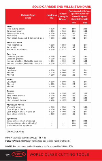
126 WORLD CLASS CUTTING TOOLS
SOLID CARBIDE END MILLS (STANDARD
HardnessHB
Material TypeGrade
SteelFree cutting steelsStructural steelPlain carbon steelAlloy steelAlloy steel, hardened & tempered steel
Stainless SteelFree machiningAustenit icFerritic & martensitic
Cast IronLamellar graphiteLamellar graphiteNodular graphite, Malleable cast ironNodular graphite, Malleable cast iron
TitaniumUnalloyedAlloyedAlloyed
NickelUnalloyedAlloyedAlloyed
CopperCopperBeta brass, bronzeAlpha brassHigh strength bronze
Aluminium AlloysWrought alloysCast alloys < 5% SiCast alloys > 5% Si < 10% SiCast alloys >10% Si
SyntheticsDuroplastics (short chipping)Thermoplastics (long chipping)Fibre reinforced synthetics
150100805030
504035
80608060
504025
302515
80808050
75754545
100100100
Recommended SurfaceSpeed in m/min for
Coated TungstenCarbide End Mills
< 120< 200< 250< 350> 350
< 250< 250< 300
< 150< 300< 200< 300
< 200< 270< 350
< 150< 270< 350
< 100< 200< 200< 470
< 100< 150< 120< 120
---
min max
< 400< 700< 850
< 1200> 1200
< 850< 850
< 1000
< 500< 1000< 700
< 1000
< 700< 900
< 1200
< 500< 900
< 1200
< 350< 700< 700
< 1500
< 350< 500< 400< 400
---
TensileStrength
N/mm2
2001501208050
807060
160120160120
806040
504020
120120120100
1351008080
300300300
TO CALCULATE:
RPM = (surface speed x 1000) / (π x d)FEED RATE in mm/min = rpm x feed per tooth x number of teeth
NOTE: For uncoated end mills reduce surface speed by 35% to 50%
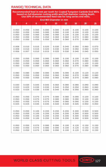
127WORLD CLASS CUTTING TOOLS
Recommended feed in mm per tooth for Coated Tungsten Carbide End Millsbased on full diameter cutting width and half diameter cutting depth.
Use 50% of recommended feed rate for long series end mills.
0.0500.0500.0500.0500.050
0.0080.0080.006
0.0500.0500.0500.050
0.0800.0500.050
0.0300.0200.020
0.0500.0500.0500.025
0.0500.0500.0500.050
0.0500.0500.050
2
0.0500.0500.0500.0500.050
0.0100.0100.007
0.0500.0500.0500.050
0.0800.0500.050
0.0300.0200.020
0.0500.0500.0500.025
0.0500.0500.0500.050
0.0500.0500.050
4
0.0600.0600.0600.0500.050
0.0150.0150.010
0.0600.0500.0600.050
0.0800.0500.050
0.0450.0300.030
0.0700.0700.0700.035
0.1000.1000.1000.100
0.0700.0700.070
6
0.1000.1000.1000.0800.080
0.0700.0700.050
0.1000.0800.1000.080
0.1200.0800.080
0.0900.0600.060
0.1000.1000.1000.050
0.5000.5000.5000.500
0.1500.1500.150
25
0.0800.0800.0800.0500.050
0.0200.0200.015
0.0800.0600.0800.060
0.0800.0500.050
0.0450.0300.030
0.0700.0700.0700.035
0.2000.2000.2000.200
0.0800.0800.080
8
0.0800.0800.0800.0600.060
0.0300.0300.020
0.0800.0600.0800.060
0.0900.0600.060
0.0600.0400.040
0.0800.0800.0800.040
0.2000.2000.2000.200
0.0900.0900.090
10
0.1000.1000.1000.0800.080
0.0600.0600.045
0.1000.0801.1000.080
0.1200.0800.080
0.0900.0600.060
0.1000.1000.1000.050
0.5000.5000.5000.500
0.1500.1500.150
20
0.1000.1000.1000.0700.070
0.0500.0500.040
0.1000.0700.1000.070
0.1000.0700.070
0.0800.0500.050
0.0900.0900.0900.045
0.3000.3000.3000.300
0.1200.1200.120
16
0.1000.1000.1000.0600.060
0.0400.0400.030
0.1000.0600.1000.060
0.0900.0600.060
0.0800.0500.050
0.0800.0800.0800.040
0.2000.2000.2000.200
0.1000.1000.100
12
RANGE) TECHNICAL DATA
End Mill Diameter in mm
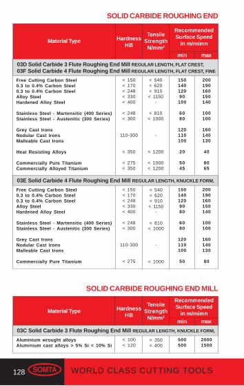
128 WORLD CLASS CUTTING TOOLS
HardnessHB
Material Type
max
RecommendedSurface Speed
in m/mimn
min
TensileStrength
N/mm2
SOLID CARBIDE ROUGHING END
Free Cutting Carbon Steel0.3 to 0.4% Carbon Steel0.3 to 0.4% Carbon SteelAlloy SteelHardened Alloy Steel
Stainless Steel - Martensitic (400 Series)Stainless Steel - Austenitic (300 Series)
Grey Cast IronsNodular Cast IronsMalleable Cast Irons
Heat Resisting Alloys
Commercially Pure TitaniumCommercially Alloyed Titanium
15014012090
100
6080
120110100
20
5045
< 150< 170< 248< 330< 400
< 248< 300
110-300
< 350
< 275< 350
200190160150140
100100
160140130
40
8065
< 540< 620< 910< 1150
-
< 810< 1000
-
< 1000
Free Cutting Carbon Steel0.3 to 0.4% Carbon Steel0.3 to 0.4% Carbon SteelAlloy SteelHardened Alloy Steel
Stainless Steel - Martensitic (400 Series)Stainless Steel - Austenitic (300 Series)
Grey Cast IronsNodular Cast IronsMalleable Cast Irons
Commercially Pure Titanium
1501401209080
6080
120110100
50
< 150< 170< 248< 330< 400
< 248< 300
110-300
< 275
200190160150140
100100
160140130
80
SOLID CARBIDE ROUGHING END MILL
HardnessHB
Material Type
max
RecommendedSurface Speed
in m/mimnmin
TensileStrength
N/mm2
< 350< 400
Aluminium wrought alloysAluminium cast alloys > 5% Si < 10% Si
500500
< 100< 120
20001500
03C Solid Carbide 3 Flute Roughing End Mill REGULAR LENGTH, KNUCKLE FORM,
< 540< 620< 910< 1150
-
< 810< 1000
-
< 1200
< 1000< 1200
03D Solid Carbide 3 Flute Roughing End Mill REGULAR LENGTH, FLAT CREST,03F Solid Carbide 4 Flute Roughing End Mill REGULAR LENGTH, FLAT CREST, FINE
03E Solid Carbide 4 Flute Roughing End Mill REGULAR LENGTH, KNUCKLE FORM,
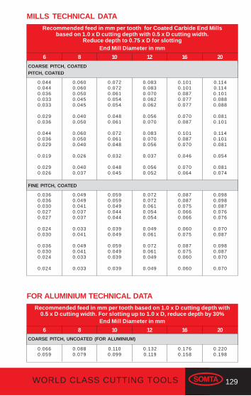
129WORLD CLASS CUTTING TOOLS
Recommended feed in mm per tooth for Coated Carbide End Millsbased on 1.0 x D cutting depth with 0.5 x D cutting width.
Reduce depth to 0.75 x D for slotting
6 8 10 12 2016
End Mill Diameter in mm
0.0440.0440.0360.0330.033
0.0290.036
0.0440.0360.029
0.019
0.0290.026
0.0600.0600.0500.0450.045
0.0400.050
0.0600.0500.040
0.026
0.0400.037
0.0720.0720.0610.0540.054
0.0480.061
0.0720.0610.048
0.032
0.0480.045
0.0830.0830.0700.0620.062
0.0560.070
0.0830.0700.056
0.037
0.0560.052
0.1140.1140.1010.0880.088
0.0810.101
0.1140.1010.081
0.054
0.0810.074
0.1010.1010.0870.0770.077
0.0700.087
0.1010.0870.070
0.046
0.0700.064
MILLS TECHNICAL DATA
0.0360.0360.0300.0270.027
0.0240.030
0.0360.0300.024
0.024
0.0490.0490.0410.0370.037
0.0330.041
0.0490.0410.033
0.033
0.0590.0590.0490.0440.044
0.0390.049
0.0590.0490.039
0.039
0.0980.0980.0870.0760.076
0.0700.087
0.0980.0870.070
0.070
0.0870.0870.0750.0660.066
0.0600.075
0.0870.0750.060
0.060
0.0720.0720.0610.0540.054
0.0490.061
0.0720.0610.049
0.049
Recommended feed in mm per tooth based on 1.0 x D cutting depth with0.5 x D cutting width. For slotting up to 1.0 x D, reduce depth by 30%
6 8 10 12 2016
FOR ALUMINIUM TECHNICAL DATA
End Mill Diameter in mm
0.0660.059
0.0880.079
0.2200.198
0.1760.158
0.1100.099
COARSE PITCH, UNCOATED (FOR ALUMINIUM)
0.1320.119
COARSE PITCH, COATEDPITCH, COATED
FINE PITCH, COATED
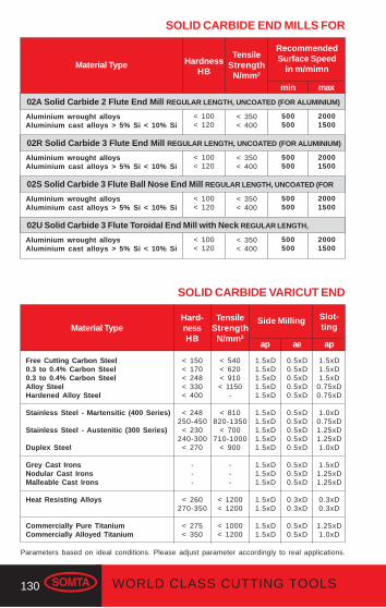
130 WORLD CLASS CUTTING TOOLS
HardnessHB
Material Type
max
RecommendedSurface Speed
in m/mimn
min
TensileStrength
N/mm2
SOLID CARBIDE END MILLS FOR
< 350< 400
Aluminium wrought alloysAluminium cast alloys > 5% Si < 10% Si
500500
< 100< 120
20001500
02A Solid Carbide 2 Flute End Mill REGULAR LENGTH, UNCOATED (FOR ALUMINIUM)
< 350< 400
Aluminium wrought alloysAluminium cast alloys > 5% Si < 10% Si
500500
< 100< 120
20001500
02R Solid Carbide 3 Flute End Mill REGULAR LENGTH, UNCOATED (FOR ALUMINIUM)
< 350< 400
Aluminium wrought alloysAluminium cast alloys > 5% Si < 10% Si
500500
< 100< 120
20001500
02S Solid Carbide 3 Flute Ball Nose End Mill REGULAR LENGTH, UNCOATED (FOR
< 350< 400
Aluminium wrought alloysAluminium cast alloys > 5% Si < 10% Si
500500
< 100< 120
20001500
02U Solid Carbide 3 Flute Toroidal End Mill with Neck REGULAR LENGTH,
Free Cutting Carbon Steel0.3 to 0.4% Carbon Steel0.3 to 0.4% Carbon SteelAlloy SteelHardened Alloy Steel
Stainless Steel - Martensitic (400 Series)
Stainless Steel - Austenitic (300 Series)
Duplex Steel
Grey Cast IronsNodular Cast IronsMalleable Cast Irons
Heat Resisting Alloys
Commercially Pure TitaniumCommercially Alloyed Titanium
SOLID CARBIDE VARICUT END
Hard-nessHB
Material TypeSlot-ting
< 150< 170< 248< 330< 400
< 248250-450
< 230240-300
< 270
---
< 260270-350
< 275< 350
ae ap
1.5xD1.5xD1.5xD
0.75xD0.75xD
1.0xD0.75xD1.25xD1.25xD1.0xD
1.5xD1.25xD1.25xD
0.3xD0.3xD
1.25xD1.0xD
Parameters based on ideal conditions. Please adjust parameter accordingly to real applications.
Side Milling
ap
0.5xD0.5xD0.5xD0.5xD0.5xD
0.5xD0.5xD0.5xD0.5xD0.5xD
0.5xD0.5xD0.5xD
0.3xD0.3xD
0.5xD0.5xD
1.5xD1.5xD1.5xD1.5xD1.5xD
1.5xD1.5xD1.5xD1.5xD1.5xD
1.5xD1.5xD1.5xD
1.5xD1.5xD
1.5xD1.5xD
TensileStrength
N/mm2
< 540< 620< 910< 1150
-
< 810820-1350
< 700710-1000
< 900
---
< 1200< 1200
< 1000< 1200
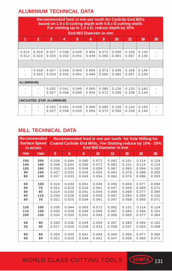
131WORLD CLASS CUTTING TOOLS
Recommended feed in mm per tooth for Carbide End Millsbased on 1.0 x D cutting depth with 0.5 x D cutting width.
For slotting up to 1.0 x D, reduce depth by 30%
1 2 3 4 65
End Mill Diameter in mm
ALUMINIUM TECHNICAL DATA
0.0140.012
0.0180.016
0.0270.024
0.0540.049
0.0450.041
0.0360.032
8 1210
0.1080.097
0.0900.081
0.0720.065
16 20
--
0.1440.130
--
0.0180.016
0.0270.024
0.0540.049
0.0450.041
0.0360.032
0.1080.097
0.0900.081
0.0720.065
--
0.1440.130
--
--
0.0320.027
0.0600.054
0.0490.045
0.0410.036
0.1200.108
0.1000.090
0.0800.072
--
0.1600.144
--
--
0.0320.027
0.0600.054
0.0490.045
0.0410.036
0.1200.108
0.1000.090
0.0800.072
--
0.1600.144
ALUMINIUM)
UNCOATED (FOR ALUMINIUM)
Recommended feed in mm per tooth for Side Milling forCoated Carbide End Mills,. For Slotting reduce by 10% - 20%
0.0440.0440.0360.0330.033
0.0300.0250.0300.0360.025
0.0440.0360.030
0.0360.020
0.0300.025
6
0.0600.0600.0490.0450.045
0.0410.0340.0410.0490.034
0.0600.0490.041
0.0490.028
0.0410.034
8
0.0720.0720.0590.0540.054
0.0490.0410.0490.0590.041
0.0720.0590.049
0.0590.033
0.0490.041
10
0.0820.0820.0670.0620.062
0.0560.0470.0560.0670.047
0.0820.0670.056
0.0670.038
0.0560.047
12
0.1240.1240.1020.0930.093
0.0840.0710.0840.1020.071
0.1240.1020.084
0.1020.058
0.0840.071
25
0.1140.1140.0940.0860.086
0.0770.0650.0770.0940.065
0.1140.0940.077
0.0940.053
0.0770.065
20
0.1010.1010.0830.0760.076
0.0690.0580.0690.0830.058
0.1010.0830.069
0.0830.047
0.0690.058
16
MILL TECHNICAL DATA
End Mill Diameter in mm
1501401209080
6050609060
120110100
5025
6050
RecommendedSurface Speed
in m/minmin max
200190160150140
1007580
11570
150130130
9040
8060
0.0360.0360.0300.0270.027
0.0240.0210.0240.0300.021
0.0360.0300.024
0.0300.017
0.0240.021
5

132 WORLD CLASS CUTTING TOOLS
SOLID CARBIDE HARD MATERIAL
RockwellC
HRCMaterial Type
Hardened Steels, IronsHardened Steels, Irons
12080
RecommendedSurface Speed
in m/min
< 4848-52
min max
140130
03G Solid Carbide 6 Flute Finishing End Mill REGULAR LENGTH, COATED
RockwellC
HRCMaterial Type
RecommendedSurface Speed
in m/minmin max
Hardened Steels, IronsHardened Steels, Irons
290200
< 4848-52
400350
03I Solid Carbide 2 Flute Ball Nose Finishing End Mill REGULAR LENGTH, COATED
Hardened Steels, IronsHardened Steels, Irons
290200
< 4848-52
400350
03J Solid Carbide 2 Flute Ball Nose Finishing End Mill LONG SERIES, COATED
RockwellC
HRCMaterial Type
RecommendedSurface Speed
in m/minmin max
Hardened Steels, IronsHardened Steels, Irons
10070
48-5252-62
120100
03H Solid Carbide Hi-Feed End Mill REGULAR LENGTH, COATED
132 WORLD CLASS CUTTING TOOLS
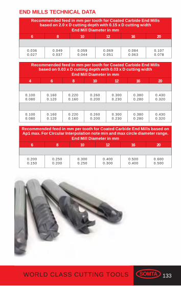
133WORLD CLASS CUTTING TOOLS
Recommended feed in mm per tooth for Coated Carbide End Millsbased on 2.0 x D cutting depth with 0.15 x D cutting width
0.0360.027
6
0.0490.037
8
0.0590.044
10
0.1070.078
20
0.0840.063
16
0.0690.051
12
END MILLS TECHNICAL DATA
End Mill Diameter in mm
Recommended feed in mm per tooth for Coated Carbide End Millsbased on 0.03 x D cutting depth with 0.03 x D cutting width
4 6 8 10 201612
End Mill Diameter in mm
0.1000.080
0.1600.120
0.2200.160
0.2600.200
0.4300.320
0.3800.280
0.3000.230
0.1000.080
0.1600.120
0.2200.160
0.2600.200
0.4300.320
0.3800.280
0.3000.230
Recommended feed in mm per tooth for Coated Carbide End Mills based onAp1 max. For Circular Interpolation note min and max circle diameter range.
6 8 10 201612
End Mill Diameter in mm
0.2000.150
0.2500.200
0.3000.250
0.6000.500
0.5000.400
0.4000.300
133WORLD CLASS CUTTING TOOLS
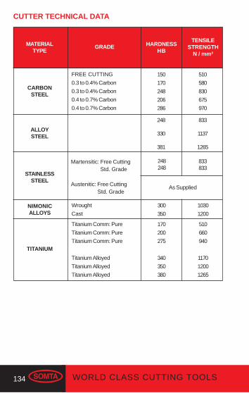
134 WORLD CLASS CUTTING TOOLS
CUTTER TECHNICAL DATA
MATERIALTYPE
GRADE
CARBONSTEEL
FREE CUTTING
0.3 to 0.4% Carbon
0.3 to 0.4% Carbon
0.4 to 0.7% Carbon
0.4 to 0.7% Carbon
HARDNESSHB
TENSILESTRENGTH
N / mm²
ALLOYSTEEL
150
170
248
206
286
510
580
830
675
970
248
330
381
833
1137
1265
STAINLESSSTEEL
Martensitic: Free Cutting Std. Grade
Austenitic: Free Cutting Std. Grade
As Supplied
248248
833833
TITANIUM
Titanium Comm: Pure
Titanium Comm: Pure
Titanium Comm: Pure
Titanium Alloyed
Titanium Alloyed
Titanium Alloyed
NIMONICALLOYS
Wrought
Cast
300
350
1030
1200
170
200
275
340
350
380
510
660
940
1170
1200
1265
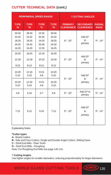
135WORLD CLASS CUTTING TOOLS
PERIPHERAL SPEED RANGE
PRIMARYCLEARANCE
† CUTTING ANGLES
8° - 20°
16-20
12-18
9-15
4-8
TYPE*A
TYPE*B
TYPE*C
TYPE*D
SECONDARYCLEARANCE
RADIALRAKE
30-40
24-32
18-25
24-32
16-25
28-40
24-32
18-25
24-32
16-20
24-32
20-26
14-20
20-26
12-20
30-40
24-32
18-25
24-32
16-25
Add 10°to
primary9° - 14°
16-20
12-18
8-14
12-16
10-15
8-12
16-20
10-16
8-12
8° - 20°Add 10°
toprimary
9° - 14°
10-205-10
10-205-10
12-165-10
12-165-10
8-154-8
8-154-8
10-205-10
10-205-10
8° - 20°Add 10°
toprimary
5-10 3-7 4-8 8° - 20° Add 10° toprimary
9° - 14°
9° - 14°
7-12 5-12 5-10 7-12 8° - 20°
Add 10°
to
primary
9° - 14°
CUTTER TECHNICAL DATA (cont.)
Explanatory Notes
*Cutter typesA - Shank CuttersB - Side and Face Cutters, Single and Double Angle Cutters, Slitting SawsC - Shell End Mills - Plain ToothD - Shell End Mills - RoughingNote: For Roughing End Mills see page 140-141.
† Cutting AnglesUse higher angles for smaller diameters, reducing proportionately for larger diameters.
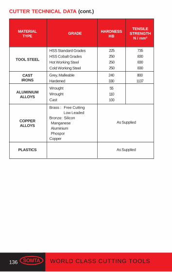
136 WORLD CLASS CUTTING TOOLS
MATERIALTYPE
GRADE
ALUMINIUMALLOYS
Wrought
Wrought
Cast
HARDNESSHB
TENSILESTRENGTH
N / mm²
COPPERALLOYS
55
110
100
PLASTICS
Brass : Free Cutting Low LeadedBronze: Silicon Manganese Aluminium PhosporCopper
As Supplied
As Supplied
CUTTER TECHNICAL DATA (cont.)
TOOL STEEL
HSS Standard Grades
HSS Cobalt Grades
Hot Working Steel
Cold Working Steel
225
250
250
250
735
830
830
830
CASTIRONS
Grey, Malleable
Hardened
240
330
800
1137

137WORLD CLASS CUTTING TOOLS
PERIPHERAL SPEED RANGE
PRIMARYCLEARANCE
† CUTTING ANGLES
10° - 20°
40-7050-8040-7025-4515-2515-2540-70
TYPE*A
TYPE*B
TYPE*C
TYPE*D
SECONDARYCLEARANCE
RADIALRAKE
200-1500
100-250
40-100
120-180
100-180
50-70
50-180
50-100
30-80
Add 10°
to
primary
20° - 28°
8° - 20°Add 10°
toprimary
9° - 14°
50-200 50-200 10° - 20°Add 10°
toprimary
9° - 14°
35-4545-7035-4520-4015-2515-2535-45
30-6040-6530-6020-3512-2012-2030-60
8° - 20° 9° - 14°
10° - 20° 20° - 28°
Explanatory Notes
*Cutter typesA - Shank CuttersB - Side and Face Cutters, Single and Double Angle Cutters, Slitting SawsC - Shell End Mills - Plain ToothD - Shell End Mills - RoughingNote: For Roughing End Mills see page 140-141.
† Cutting AnglesUse higher angles for smaller diameters, reducing proportionately for larger diameters.
CUTTER TECHNICAL DATA (cont.)
10-20
10-16
10-16
10-16
10-20
10-20
10-16
10-16
8-15
8-13
8-13
8-13
10-20
10-16
10-16
10-16
8° - 20°Add 10°
toprimary
9° - 14°
16-20
12-16
16-20
10-14
12-16
10-12
20-28
16-228° - 20°
Add 10° to
primary9° - 14°
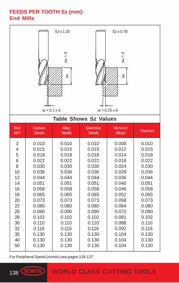
138 WORLD CLASS CUTTING TOOLS
FEEDS PER TOOTH Sz (mm):End Mills
345681012141618202225283032354050
EndMill
Table Shows Sz Values
CarbonSteels
AlloySteels
StainlessSteels
NimonicAlloys Titanium
0.0100.0150.0180.0220.0300.0360.0440.0510.0580.0650.0730.0800.0900.1020.1100.1160.1300.1300.130
0.0100.0150.0180.0220.0300.0360.0440.0510.0580.0650.0730.0800.0900.1020.1100.1160.1300.1300.130
0.0100.0150.0180.0220.0300.0360.0440.0510.0580.0650.0730.0800.0900.1020.1100.1160.1300.1300.130
0.0080.0120.0140.0180.0240.0290.0360.0400.0460.0520.0580.0640.0720.0810.0880.0920.1040.1040.104
0.0100.0150.0180.0220.0300.0360.0440.0510.0580.0650.0730.0800.0900.1020.1100.1160.1300.1300.130
Sz x 1.25 Sz x 0.78
ar = 0.1 x d ar = 0.25 x d
aa =
d
aa =
d
aaaa
For Peripheral Speed (m/min) see pages 134-137
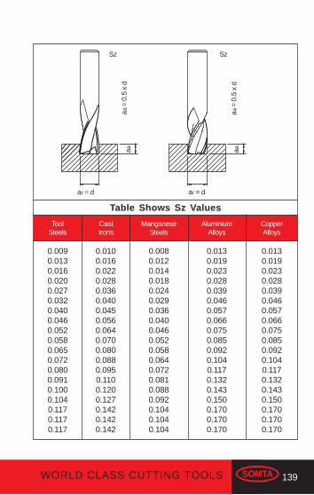
139WORLD CLASS CUTTING TOOLS
Table Shows Sz Values
ToolSteels
CastIrons
ManganeseSteels
AluminiumAlloys
CopperAlloys
0.0090.0130.0160.0200.0270.0320.0400.0460.0520.0580.0650.0720.0800.0910.1000.1040.1170.1170.117
0.0100.0160.0220.0280.0360.0400.0450.0560.0640.0700.0800.0880.0950.1100.1200.1270.1420.1420.142
0.0080.0120.0140.0180.0240.0290.0360.0400.0460.0520.0580.0640.0720.0810.0880.0920.1040.1040.104
0.0130.0190.0230.0280.0390.0460.0570.0660.0750.0850.0920.1040.1170.1320.1430.1500.1700.1700.170
0.0130.0190.0230.0280.0390.0460.0570.0660.0750.0850.0920.1040.1170.1320.1430.1500.1700.1700.170
Sz Sz
ar = d
aa =
0.5
x d
aa =
0.5
x d
aaaa
ar = d
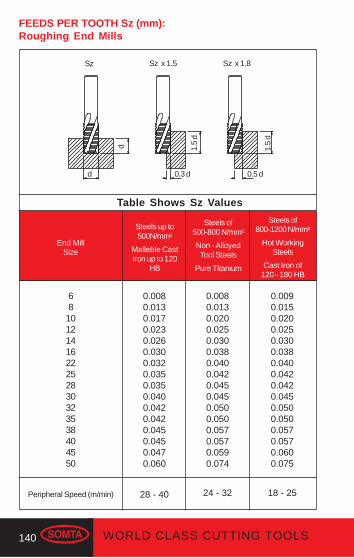
140 WORLD CLASS CUTTING TOOLS
End MillSize
Table Shows Sz Values
Steels up to500N/mm²
Malleble CastIron up to 120
HB
Steels of500-800 N/mm²
Non - AlloyedTool Steels
Pure Titanium
Steels of800-1200 N/mm²
Hot WorkingSteels
Cast Iron of120 - 180 HB
0.0080.0130.0170.0230.0260.0300.0320.0350.0350.0400.0420.0420.0450.0450.0470.060
28 - 40
681012141622252830323538404550
0.0080.0130.0200.0250.0300.0380.0400.0420.0450.0450.0500.0500.0570.0570.0590.074
24 - 32
0.0090.0150.0200.0250.0300.0380.0400.0420.0420.0450.0500.0500.0570.0570.0600.075
18 - 25
FEEDS PER TOOTH Sz (mm):Roughing End Mills
Peripheral Speed (m/min)
Sz Sz x 1.5 Sz x 1.8
d 0.3 d 0.5 d
d 1.5
d
1.5
d
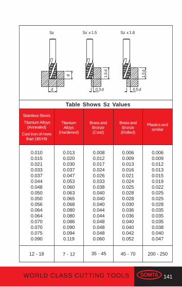
141WORLD CLASS CUTTING TOOLS
Table Shows Sz Values
Brass andBronze(Cast)
Brass andBronze(Rolled)
Plastics andsimilar
0.0080.0120.0170.0240.0260.0330.0380.0400.0400.0400.0440.0440.0480.0480.0480.060
35 - 45
0.0060.0090.0130.0160.0210.0240.0250.0280.0280.0300.0360.0360.0400.0400.0420.052
45 - 70
0.0060.0090.0120.0130.0150.0190.0220.0250.0250.0280.0350.0350.0350.0380.0400.047
200 - 250
Stainless Steels
Titanium Alloys(Annealed)
Cast Iron of morethan 180 HB
TitaniumAlloys
(Hardened)
0.0100.0150.0210.0330.0370.0440.0480.0500.0500.0560.0640.0640.0700.0700.0750.090
12 - 18
0.0130.0200.0300.0370.0470.0530.0600.0630.0650.0680.0800.0800.0860.0900.0940.119
7 - 12
Sz Sz x 1.5 Sz x 1.8
d 0.3 d 0.5 d
d 1.5
d
1.5
d
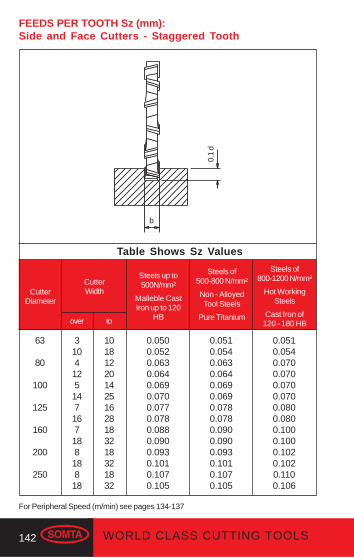
142 WORLD CLASS CUTTING TOOLS
CutterDiameter
Table Shows Sz Values
CutterWidth
Steels up to500N/mm²
Malleble CastIron up to 120
HB
Steels of500-800 N/mm²
Non - AlloyedTool Steels
Pure Titanium
Steels of800-1200 N/mm²
Hot WorkingSteels
Cast Iron of120 - 180 HB
0.0500.0520.0630.0640.0690.0700.0770.0780.0880.0900.0930.1010.1070.105
63
80
100
125
160
200
250
0.0510.0540.0630.0640.0690.0690.0780.0780.0900.0900.0930.1010.1070.105
0.0510.0540.0700.0700.0700.0700.0800.0800.1000.1000.1020.1020.1100.106
FEEDS PER TOOTH Sz (mm):Side and Face Cutters - Staggered Tooth
310412514716718818818
1018122014251628183218321832
over to
b0.
1 d
For Peripheral Speed (m/min) see pages 134-137
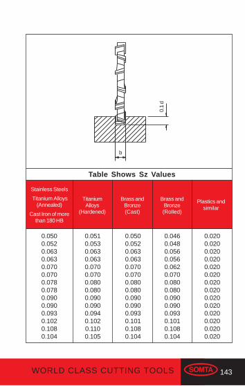
143WORLD CLASS CUTTING TOOLS
Table Shows Sz Values
Brass andBronze(Cast)
Brass andBronze(Rolled)
Plastics andsimilar
0.0500.0520.0630.0630.0700.0700.0800.0800.0900.0900.0930.1010.1080.104
0.0460.0480.0560.0560.0620.0700.0800.0800.0900.0900.0930.1010.1080.104
0.0200.0200.0200.0200.0200.0200.0200.0200.0200.0200.0200.0200.0200.020
Stainless Steels
Titanium Alloys(Annealed)
Cast Iron of morethan 180 HB
TitaniumAlloys
(Hardened)
0.0500.0520.0630.0630.0700.0700.0780.0780.0900.0900.0930.1020.1080.104
0.0510.0530.0630.0630.0700.0700.0800.0800.0900.0900.0940.1020.1100.105
b
0.1
d

144 WORLD CLASS CUTTING TOOLS
Type
Table Shows Sz Values
CutterDiameter
Steels up to500N/mm²
Malleble CastIron up to 120
HB
Steels of500-800 N/mm²
Non - AlloyedTool Steels
Pure Titanium
Steels of800-1200 N/mm²
Hot WorkingSteels
Cast Iron of120 - 180 HB
0.0800.0800.1000.1000.1000.1000.105
40506380100125160
0.0800.0800.1000.1000.1000.1000.105
0.0800.0800.1000.1000.1000.1000.105
40506380100125160
0.0600.0700.0750.1000.1100.1150.120
0.0600.0700.0800.1000.1100.1150.120
0.0600.0700.0700.1000.1100.1150.125
0.75 d
0.1
d
Plain Tooth
PlainTooth
RoughingForm
FEEDS PER TOOTH Sz (mm):Shell End Mills
For Peripheral Speed (m/min) see pages 134-137
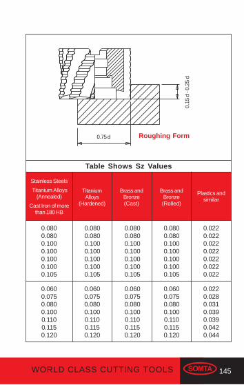
145WORLD CLASS CUTTING TOOLS
Table Shows Sz Values
Brass andBronze(Cast)
Brass andBronze(Rolled)
Plastics andsimilar
0.0800.0800.1000.1000.1000.1000.105
0.0800.0800.1000.1000.1000.1000.105
0.0220.0220.0220.0220.0220.0220.022
0.0600.0750.0800.1000.1100.1150.120
Stainless Steels
Titanium Alloys(Annealed)
Cast Iron of morethan 180 HB
TitaniumAlloys
(Hardened)
0.0800.0800.1000.1000.1000.1000.105
0.0800.0800.1000.1000.1000.1000.105
0.0600.0750.0800.1000.1100.1150.120
0.0600.0750.0800.1000.1100.1150.120
0.0600.0750.0800.1000.1100.1150.120
0.0220.0280.0310.0390.0390.0420.044
0.75 d
0.15
d -
0.25
d
Roughing Form
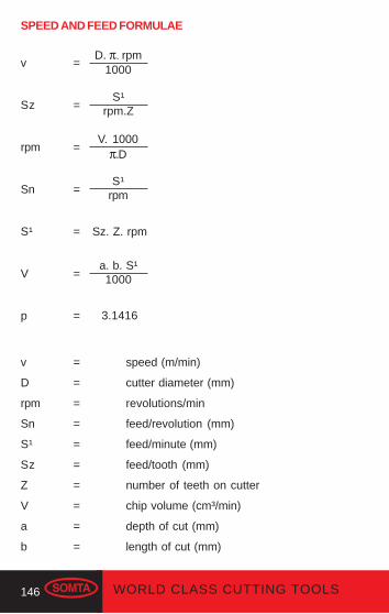
146 WORLD CLASS CUTTING TOOLS
v =
Sz =
rpm =
Sn =
S¹ =
V =
p =
v = speed (m/min)
D = cutter diameter (mm)
rpm = revolutions/min
Sn = feed/revolution (mm)
S¹ = feed/minute (mm)
Sz = feed/tooth (mm)
Z = number of teeth on cutter
V = chip volume (cm³/min)
a = depth of cut (mm)
b = length of cut (mm)
D. π. rpm1000
S¹rpm.Z
V. 1000π.D
S¹rpm
Sz. Z. rpm
a. b. S¹1000
3.1416
SPEED AND FEED FORMULAE

147WORLD CLASS CUTTING TOOLS
+12 0
+150
+18 0
+210
+250
+300
+350
+10 0
H7
+70-70
+60-60
+50-50
+42-42
+35-35
+24-24
3 to6mm
6 to 10mm
10 to18mm
18 to30mm
30 to50mm
50 to80mm
80 to120mm
-30-105
-40-130
-50-160
-65-195
-80-240
-100-290
-120-340
-20-38
-25-47
-32-59
-40-73
-50-89
-60-106
-72-126
0-75
0-90
0-110
0-130
0-160
0-190
0-220
0-120
0-150
0-180
0-210
0-250
0-300
0-350
+150 -150
+180 -180
+215 -215
+260 -260
+310 -310
+370 -370
+435 -435
+375 -375
+450 -450
+550 -550
+650 -650
+800 -800
+950 -950
+1100 -1100
3mm
-20-80
-14-28
d11
0-60
0-100
+300 -300
+125 -125
Tolerances in μm = 1 micron (1/1000mm)
DIAMETER OR WIDTH
0-6
0-14
0-8
0-9
0-11
0-13
0-16
0-19
0-22
0-18
0-22
0-27
0-33
0-39
0-46
0-54
+90-0
+110-0
+130-0
+160-0
+190-0
+220-0
+60-0
+75-0
+29-29
+20-20
e8
h11
h12
js16
h6
h8
k11
js14
Tol.
TOLERANCES
+120 -0
+150-0
+180 -0
+210-0
+250-0
+300-0
+350-0
+100 -0
K12
h7 0-10
0-12
0-15
0-18
0-21
0-25
0-30
0-35
k10 +400
+480
+580
+700
+840
+1000
+1200
+1400
js10
GENERAL INFORMATION
+900
+1100
+1300
+1600
+1900
+2200
+600
+750
H11

148 WORLD CLASS CUTTING TOOLS
PERIPHERAL SPEED TO rpm CONVERSION CHART
METRESPER MIN
5 10 20 30 40
Dia.mm
123456789
1011121314151618202224262830354045506375
100
15917955303983182652271991771591451331221141061008980736761575345403532252116
31821590106079563653045539835331828926524522721219917715914513312211310691807064504232
6364318221201590127210609107967066365785304904544243983543182902662442282121821601401281008464
95464770318023851908159013651194105995486779573568163659753147743539936634231827324021019215012696
1272863604240318025442120182015921412127211561060980908848796708636580532488456424364320280256200168128
Revolutions per Minute
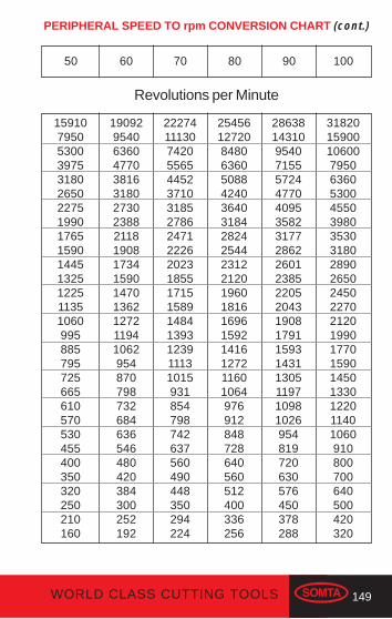
149WORLD CLASS CUTTING TOOLS
1591079505300397531802650227519901765159014451325122511351060995885795725665610570530455400350320250210160
50 70 80 90 10060
190929540636047703816318027302388211819081734159014701362127211941062954870798732684636546480420384300252192
222741113074205565445237103185278624712226202318551715158914841393123911131015931854798742637560490448350294224
2545612720848063605088424036403184282425442312212019601816169615921416127211601064976912848728640560512400336256
286381431095407155572447704095358231772862260123852205204319081791159314311305119710981026954819720630576450378288
31820159001060079506360530045503980353031802890265024502270212019901770159014501330122011401060910800700640500420320
Revolutions per Minute
PERIPHERAL SPEED TO rpm CONVERSION CHART (cont.)

150 WORLD CLASS CUTTING TOOLS
INCH-MILLIMETER CONVERSION TABLE
3"m m
76.20076.59776.99477.39177.78878.18478.58178.97879.37579.77280.16980.56680.96281.35981.75682.15382.55082.94783.34483.74184.13884.53484.93185.32885.72586.12286.51986.91687.31287.70988.10688.503
2"m m
50.80051.19751.59451.99152.38852.78453.18153.57853.97554.37254.76956.16655.56255.95956.35656.75357.15057.54757.94458.34158.73859.13459.53159.92860.32560.72261.11961.51661.91262.30962.70663.103
1"m m
25.40025.79726.19426.59126.98827.38427.78128.17828.57528.97229.36929.76630.16230.59930.95631.35331.75032.14732.54432.94133.33833.73434.13134.52834.92535.32235.71936.11636.51236.90937.30637.703
0"m m
0.3970.7941.1911.5881.9842.3812.7783.1753.5723.9694.3664.7625.1595.5565.9536.3506.7477.1447.5417.9388.3348.7319.1289.5259.92210.31910.71611.11211.50911.90612.303
0 . . . . .1/64 . . . .1/32 . . . .3/64 . . . .1/16 . . . .5/64 . . . .3/32 . . . .7/64 . . . .1/8 . . . . .9/64 . . . .5/32 . . . .11/64 . . . .3/16 . . . .13/64 . . . .7/32 . . . .15/64 . . . .1/4 . . . . .17/64 . . . .9/32 . . . .19/64 . . . .5/16 . . . .21/64 . . . .11/32 . . . .23/64 . . . .3/8 . . . . .25/64 . . . .13/32 . . . .27/64 . . . .7/16 . . . .29/64 . . . .15/32 . . . .31/64 . . . .

151WORLD CLASS CUTTING TOOLS
INCH-MILLIMETER CONVERSION TABLE (cont)
3"m m
89.90089.29789.69490.09190.48890.88491.28191.67892.07592.47192.86893.26693.66294.05994.45694.85395.25095.64796.04496.44196.83897.23497.63198.02898.42598.28299.21999.616100.012100.409100.806101.203
2"m m
63.50063.89764.29464.69165.08865.48465.88166.27866.67567.07167.46867.86668.26268.85969.05669.45369.85070.24770.64471.04171.43871.83472.23172.62873.02573.42273.81974.21674.61275.00975.40675.803
1"m m
38.10038.49738.89439.29139.68840.08440.48140.87841.27541.67142.06842.46642.86243.85943.65644.05344.45044.84745.24445.64146.03846.43446.83147.22847.62548.02248.41948.81649.21249.60950.00650.403
0"m m
12.70013.09713.49413.89114.28814.68415.08115.74815.87516.27116.66817.06617.46217.85918.25618.65319.05019.44719.84420.24120.63821.03421.43121.82822.22522.62223.01923.41623.81224.20924.60625.003
1/2 . . . . .33/64 . . . .17/32 . . . .35/64 . . . .9/16 . . . .37/64 . . . .19/32 . . . .39/64 . . . .5/8 . . . . .41/64 . . . .21/32 . . . .43/64 . . . .11/16 . . . .45/64 . . . .23/32 . . . .47/64 . . . .3/4 . . . . .49/64 . . . .25/32 . . . .51/64 . . . .13/16 . . . .53/64 . . . .27/32 . . . .55/64 . . . .7/8 . . . . .57/64 . . . .29/32 . . . .59/64 . . . .15/16 . . . .61/64 . . . .31/32 . . . .63/64 . . . .

152 WORLD CLASS CUTTING TOOLS
APPROXIMATE HARDNESS AND TENSILESTRENGTH CONVERSIONS
TENSILE STRENGTH
MPa orN/mm²
HRB HRC HV HB Tons/inch²
50556065707580859095100——————————————————————————
——————————202224262830323436384042444648505254565860646668707580
95100110120130140150165185205230240255265280295310325345360380405425450480505545580615655695790855940107514801865
90100105110120130140160175195220230240250265280290310325345365385405430455480———————————
212325272931343740455053565962656872757883889296102108112117122130135150163179197——
32035039042045048052057062069077082086091096010001050111011501200128013601420148015401670172018001890200021002320251027703030——
HRB = Hardness Rockwell BHRC = Hardness Rockwell CHV = Hardness Vickers. Also DPN, VPN, DPH, VPHHB = Hardness Brinell. Also BHN
Note: These values should be treated as approximate only and aresuitable for calculating speeds and feeds or for general informationpurposes. Do not use for treated high speed steel.
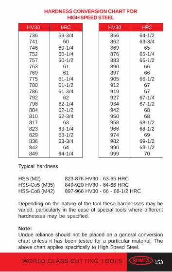
153WORLD CLASS CUTTING TOOLS
HARDNESS CONVERSION CHART FORHIGH SPEED STEEL
HV30 HRC HV30 HRC
736741746752757763769775780786792798804810817823829836842849
59-3/460
60-1/460-1/460-1/2
6161
61-1/461-1/261-3/4
6262-1/462-1/262-3/4
6363-1/463-1/263-3/4
6464-1/4
856862869876883890897905912919927934942950958966974982990999
64-1/263-3/4
6565-1/465-1/2
6666
66-1/26767
67-1/467-1/2
6868
68-1/268-1/2
6969-1/269-1/2
70
Typical hardness
HSS (M2) 823-876 HV30 - 63-65 HRCHSS-Co5 (M35) 849-920 HV30 - 64-66 HRCHSS-Co8 (M42) 897-966 HV30 - 66 - 68-1/2 HRC
Depending on the nature of the tool these hardnesses may bevaried, particularly in the case of special tools where differenthardnesses may be specified.
Note:Undue reliance should not be placed on a general conversionchart unless it has been tested for a particular material. Theabove chart applies specifically to High Speed Steel.

154 WORLD CLASS CUTTING TOOLS
USEFUL FORMULAE
rpm = Surface Speed (metres/min) ÷Dia (mm) x π
1000
Surface Speed (metres/min) = x rpmDia (mm) x π
1000
Feed Rate (mm/rev) =Feed rate (mm/min
rpm
Penetration rate (mm/min) = rpm x feed rate (mm/rev)

155WORLD CLASS CUTTING TOOLS
Trigonometry
Formulae for the solution of Formulae for the solution ofRIGHT ANGLED OBLIQUE ANGLEDTRIANGLES TRIANGLES
A
B C
cb
a
θθθθθ
A
B C
c
a
b
Tan θ θ θ θ θ =
Sin θ θ θ θ θ =
Cos θ θ θ θ θ =
oppositeadjacent
oppositehypotenuse
adjacenthypotenuse
=
=
=
ca
cb
ab
The Sine rule: a b cSin A Sin B Sin CThe Cosine rule:a² = b² + c² - 2bc Cos Ab² = a² + c² - 2ac Cos Bc² = a² + b² - 2ab Cos C
= =
USEFUL VALUES IN TRIGNOMETRICAL RATIOSFor right angled triangles
60°
30°
12
45°
45°1
1√ 3
√ 2
ANGLES 30° - 45° - 60°
θθθθθ Tan θθθθθ Sin θθθθθ Cos θθθθθ
30°
45°
60°
13
12√ = 0.577350 = 0.500000
32
√= 0.866025
1 12√ = 0.707107
12√ = 0.707107
3 = 1.732051√ 32
√= 0.866025
12 = 0.500000

156 WORLD CLASS CUTTING TOOLS
Useful formulae for FindingDimensions of Circles, Squares, etc.
D is diameter of stock necessary to turn shape desired.E is distance “across flats,” or diameter of inscribed circle.C is depth of cut into stock turned to correct diameter.
C
E
D
CE
D
CE
D
CE
D
C
E
D
TRIANGLE
E = side x 0.57735D = side x 1.1547 = 2ESide = D x 0.866C = E x 0.5 = D x 0.25
SQUARE
E = side = D x 0.7071D = side x 1.4142 = diagonalSide = D x 0.7071C = D x 0.14645
PENTAGON
E = side x 1.3764 = D x 0.809D = side x 0.7013 = E x 1.2361Side = D x 0.5878C = D x 0.0955
HEXAGON
E = side x 1.7321 = D x 0.866D = side x 2 = E x 1.1547Side = D x 0.5C = D x 0.067
OCTAGON
E = side x 2.4142 = D x 0.9239D = side x 2.6131 = E x 1.0824Side = D x 0.3827C = D x 0.038
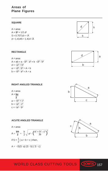
157WORLD CLASS CUTTING TOOLS
SQUARE
A = areaA = S² = 1/2 d²S = 0.7071d = √Ad = 1.414S = 1.414 √A
RECTANGLE
A = areaA = ab = a √d² - a² = b √d² - b²d = √a² + b²a = √d² - b² = A ÷ bb = √d² - a² = A ÷ a
RIGHT ANGLED TRIANGLE
A = areaA = bc 2a = √b² + c²b = √a² - c²c = √a² - b²
ACUTE ANGLED TRIANGLE
A = area
A =
if S = ( a + b + c ) then,
A = √S(S -a) (S - b) ( S - c)
Areas ofPlane Figures
a² - ( )12
s
s
d
d
b
a
c
b
a
c
b
a
hbh2 =
b2 √
a² + b² - c²2b
²

158 WORLD CLASS CUTTING TOOLS
OBTUSE ANGLED TRIANGLE
A = area
A =
if S = ( a + b + c ) then,
A = √S(S -a) (S - b) ( S - c)
CIRCLE
A = area C = circumferenceA = π r² = 3.1416 r²
A = = 0.7854 d²
C = 2 πr = 6.2832r = 3.1416d
r = C ÷ 6.2832 = √A ÷ 3.1416 = 0.564 √A
d = C ÷ 3.1416 = √A ÷ 0.7854 = 1.128 √A
REGULAR HEXAGON
A = areaR = radius of circumscribed circler = radius of inscribed circleA = 2.598S² = 2.598R² = 3.464r²R = S = 1.155rr = 0.866S = 0.866R
= a² - ( )√
c² - a² - b²2b
²
12
b2
c
b
a
rd
h
r
60°R
s
π d²4
The construction of a regular hexagon forms six equilateral triangles,thusthe area of the hexagon can also be found by calculating the area of theequilateral triangle and multiplying the result by six.
bh2

159WORLD CLASS CUTTING TOOLS
Cone of Included Angle Angle with Centre Line
1 in 22-1/21 in 33-1/21 in 44-1/21 in 55-1/21 in 66-1/21 in 77-1/21 in 88-1/21 in 99-1/2
1 in 101 in 111 in 121 in 131 in 141 in 151 in 161 in 171 in 181 in 191 in 201 in 251 in 301 in 351 in 401 in 451 in 481 in 501 in 551 in 60
28°22°18°16°14°12°11°10°9°8°8°7°7°6°6°6°5°5°4°4°4°3°3°3°3°3°2°2°1°1°1°1°1°1°1°
4´37´55´15´15´40´25´23´31´47´10´37´9´43´21´1´43´12´46´24´5´49´34´22´10´0´51´17´54´38´25´16´11´8´2´57´
20″12″28″38″0″
50″16″20″36″52″16″43″10″58″34″32″31″18″19″16″26″6″
48″9″
58″54″52″31″36″14″56″24″37″46″29″17″
14°11°9°8°7°6°5°5°4°4°4°3°3°3°3°3°2°2°2°2°2°1°1°1°1°1°1°1°
2´18´27´7´7´
20´42´11´45´23´5´
48´34´21´10´0´
51´36´23´12´2´
54´47´41´35´30´25´8´
57´49´42´38´35´34´31´28´
10″36″44″49″30″25″38″40″48″56″8″52″35″59″47″46″46″9″9″8″43″33″24″4″29″27″56″46″18″7″58″12″48″23″14″39″
USEFUL TAPERS
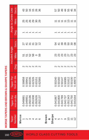
160 WORLD CLASS CUTTING TOOLS
MO
RS
E T
AP
ER
S A
ND
BR
OW
N &
SH
AR
PE
TA
PE
RS
Tape
rN
umbe
rTa
per
Per
mm
on
dia.
Tape
r P
erfo
ot o
n di
a.In
clud
ed A
ngle
Ang
le t
o C
entr
e Li
neD
eg.
Min
s.S
ecs
.D
eg.
Min
s.S
ecs
.
Mo
rse
1 2 3 4 5 6
Bro
wn
&S
ha
rpe
4 5 7 9 10 11 12
0.04
9881
0.04
9951
0.05
0196
0.05
1938
0.05
2626
0.05
2137
0.04
1867
0.04
1800
0.04
1789
0.04
1737
0.05
1343
0.04
1750
0.04
1644
0.59
858
0.59
941
0.60
235
0.62
326
0.63
151
0.62
565
0.50
240
0.50
160
0.50
147
0.50
085
0.51
612
0.50
100
0.49
973
2 2 2 2 3 2 2 2 2 2 2 2 2
51 51 52 58 0 59 23 23 23 23 27 23 23
27 41 31 31 52 12 54 41 39 28 50 30 08
1 1 1 1 1 1 1 1 1 1 1 1 1
25 25 26 29 30 29 11 11 11 11 13 11 11
43 50 16 15 26 36 57 50 49 44 55 45 34

161WORLD CLASS CUTTING TOOLS
CONVERSION FACTORS
British - MetricTo convert Multiply byInches to millimetres 25.40Feet to metres 0.3048Yards to metres 0.9144Miles to kilometres 1.60934Square inches to square centimetres 6.4516Square feet to square metres 0.092903Square yards to square metres 0.836127Square miles to square kilometres 2.58999Cubic inches to cubic centimetres 16.3871Cubic feet to cubic metres 0.028317Cubic yards to cubic metres 0.764555Pints to litres 0.568261Gallons to litres 4.54609Ounces to grams 28.3495Pounds to kilograms 0.453592Tons to tonnes (1.000kg) 1.01605Lb/sq.in. to kg/sq.m 703.070Fahrenheit = 9/5°C+32
Metric - BritishTo convert Multiply byMillimetres to inches 0.0393701Metres to feet 3.28084Metres to yards 1.09361Kilometres to miles 0.621371Square centimetres to square inches 0.1550Square metres to square feet 10.76391Square metres to square yards 1.19599Square kilometres to square miles 0.3861Cubic centimetres to cubic inches 0.061024Cubic metres to cubic feet 35.3147Litres to pints 1.76Litres to gallons 0.22Grams to ounces 0.035274Kilograms to pounds 2.20462Tonnes to tons 0.984207Kg/sq.mm to lb/sq.in. 0.001422Centigrade (Celcius) = 5/9° (F-32)

162 WORLD CLASS CUTTING TOOLS
.1mm
.2mm
.3mm8079
1/64.4mm
7877
.5mm767574
.6mm737271
.7mm706968
1/32.8mm
676665
.9mm64636261
1mm6059585756
3/64555453
1/165251504948
5/6447
2mm46
Decimal Equivalentsmm-Inch-Wire
.0039
.0079
.0118
.0135
.0145
.0156
.0157
.0160
.0180
.0197
.0200
.0210
.0225
.0236
.0240
.0250
.0260
.0276
.0280
.0292
.0310
.0312
.0315
.0320
.0330
.0350
.0354
.0360
.0370
.0380
.0390
.0394
.0400
.0410
.0420
.0430
.0465
.0469
.0520
.0550
.0595
.0625
.0635
.0670
.0700
.0730
.0760
.0781
.0785
.0787
.0810
DecimalInch
mm-Inch-Wire
DecimalInch
mm-Inch-Wire
DecimalInch
mm-Inch-Wire
DecimalInch
45444342
3/32414039383736
7/6435343332
3mm311/8302928
9/642726252423
5/3222
4mm21201918
11/641716151413
3/161211109
5mm87
13/646
.0820
.0860
.0890
.0935
.0938
.0960
.0980
.0995
.1015
.1040
.1060
.1094
.1100.1110.1130.1160.1181.1200.1250.1285.1360.1405.1406.1440.1470.1495.1520.1540.1562.1570.1575.1590.1610.1660.1695.1719.1730.1770.1800.1820.1850.1875.1890.1910.1935.1960.1969.1990.2010.2031.2040
543
7/3221A
15/646mm
BCD
1/4 & EFG
17/64HI
7mmJK
9/32LM
19/64N
5/168mm
OP
21/64QR
11/32S
9mmT
23/64U3/8VW
25/6410mm
XY
13/32Z
27/6411mm7/16
.2055
.2090
.2130
.2188
.2210
.2280
.2340
.2344
.2362
.2380
.2420
.2460
.2500
.2570
.2610
.2656
.2660
.2720
.2756
.2770
.2810
.2812
.2900
.2950
.2969
.3020
.3125
.3150
.3160
.3230
.3281
.3320
.3390
.3438
.3480
.3543
.3580
.3594
.3680
.3750
.3770
.3860
.3906
.3937
.3970
.4040
.4062
.4130
.4219
.4331
.4375
29/6415/3212mm31/641/2
13mm33/6417/3235/6414mm9/1637/6415mm19/3239/645/8
16mm41/6421/3217mm43/6411/1645/6418mm23/3247/6419mm
3/449/6425/3220mm51/6413/1621mm53/6427/3255/6422mm
7/857/6423mm29/3259/6415/1624mm61/6431/3225mm63/64
1”
.4531
.4688
.4724
.4844
.5000
.5118
.5156
.5313
.5469
.5512
.5625
.5781
.5906
.5938
.6094
.6250
.6299
.6406
.6562
.6693
.6719
.6875
.7031
.7087
.7188
.7344
.7480
.7500
.7656
.7812
.7874
.7969
.8125
.8268
.8281
.8438
.8594
.8661
.8750
.8906
.9055
.9062
.9219
.9375
.9449
.9531
.9688
.9843
.98441.0000
NUMBER AND LETTER DRILL SIZES

Head Office and Surface Coating Division
Somta House, 290-294 Moses Mabhida (Edendale) Road, Pietermaritzburg, 3201Private Bag X401, Pietermaritzburg, 3200South Africa
Tel: Factory: +27 33 355 6600Fax: Factory: +27 33 394 0564Tel: Sales: +27 11 390 8700 (Local)Fax: Sales: +27 11 397 6720/1 (Local)Email: [email protected] (Local)Tel: Sales: +27 33 355 6600 (Exports)Fax: Sales: +27 33 394 7509 (Exports)Email: [email protected] (Exports)
Gauteng Sales Office
43 Bisset Road, Hughes Ext. 7, Boksburg, 1459P.O.Box 14212, Witfield, 1467South Africa
Tel: +27 11 390 8700Fax: +27 11 397 6720/1Sharecall: 086 010 4367Email: [email protected]
Technical Information:
Email: [email protected] Free Number: 0800-331-399Technical Representatives Cell Numbers: 082 801 8930, 082 800 5259, 082 906 3486082 806 8202, 082 803 0505
Manufacturers & Suppliers
of Drills, Reamers, End Mills,
Bore Cutters, Taps & Dies,
Toolbits, Solid Carbide
Tooling, Carbide Insert
Tooling, Custom Tools
and Surface Coatings
ISO
9 001