cp-4 and cp-4uh
TRANSCRIPT

Waterous Company • 125 Hardman Avenue South • South Saint Paul, MN 55075 • (651) 450-5000www.waterousco.com
CP-4 and CP-4UHOverhaul Instructions
Form Number F-2915 Issue Date: May 27, 2021Revision Date: Jul 6, 2021


Table of ContentsSafety 4Safety Precautions 4
Introduction 5Using this Document 5
Viewing the Document Electronically 5Printing the Document 5
Symbols 5Identifying Exterior Components—Top 6Identifying Exterior Components—Bottom 7
Disassembly 8Preparing to Disassemble the Pump 8Tools Required 8Preparing the Apparatus 8Best Practices 8Removing the Pump 8Disassembling the Pump Components 8Optional Equipment 8Separating the Pump and Transmission 9
Removing the Packing Cooler Hose 9Removing the Bearing Housing 10Removing the Packing Housing Screws 11Removing the Pump Body Hardware 12Removing the Dowel Pins 14Removing the Upper Pump Body and Bearing Cover 15Removing the Lower Pump Body 16Removing the Impeller Shaft Assembly 17
Removing the Impeller Shaft Components 18
Assembly 21Preparing to Assemble the Pump 21Tools Required 21Best Practices 21Optional Equipment 21Assembling the Pump Components 21Installing the Pump 21Understanding the Illustrations 21Impeller Shaft Assembly 22Assembling the Bearing Housing 23Assembling the Impeller Shaft 24Installing and Tightening the Packing 27Pump Body Assembly 28Installing the Lower Pump Body 30Installing the Bearing Cover 31Installing the Upper Pump Body 32Installing the Pump Body Hardware 34Installing the Packing Housing Hardware 35Installing the Flinger Ring and Bearing 36Installing the Bearing Housing 37Installing the Packing Cooler Hose 38Testing After Installation 39

4 | 41
Safety Introduction Disassembly Assembly
Safety Precautions• Read and understand this document before you begin the overhaul.• Read and understand all the notices and safety precautions.• Be aware that these instructions are only guidelines and are not meant to be
definitive. Contact Waterous when you have questions.• Do not overhaul this equipment if you are not familiar with the tools and skills
needed to safely perform the required procedures.• Do not modify the equipment.• Waterous reserves the right to make modifications to the instructions without
notice.
Always support heavyequipment while servicing.
Unsupported equipmentmay shift or fall during dis-assembly, causing injuryor damage.
Unsupported Equipment•
•
Do not touch the surfaceduring operation––allowit to cool after operating.
Hot surface can burn you.
Hot Surface•
•
Drain the pump after useand before servicing.
Liquid ejected at highpressure can cause serious injury.
High Pressure•
•

5 | 41
Safety Introduction Disassembly Assembly
Use this document to overhaul your Waterous equipment. Please understand the following conditions:• Be aware that these instructions are only guidelines and are not meant to be
definitive. Contact Waterous when you have questions.• Understand that your configuration may require additional steps, that are not
described in the illustrations or instructions, to perform the overhaul.• The equipment described in this document is intended to be overhauled by
a person or persons with the necessary skills and knowledge to perform the overhaul.
This document is divided into the following sections:Safety
This section describes general precautions and alert symbols that are in this document.Introduction
This section is an overview of the document.Disassembly
This section describes disassembly procedures.Assembly
This section describes assembly procedures.
Using this DocumentUse the guidelines below when viewing this document.
Viewing the Document Electronically• View this document in landscape orientation.• Use the table of contents to navigate directly to that section.• Text with this appearance is linked to a reference.
Printing the Document• The document is viewed the best when printed in color.• The print on both sides and flip on long edge features can provide the
best results.• Use a 3-ring binder to store the document.
SymbolsSymbols are used to illustrate additional tools or operations that are required to complete the instruction.
Arbor press—This symbol tells you to use an arbor press to complete this step.
Discard—This symbol tells you to discard or recycle the part in accordance with local regulations.
Finger tight, then full turn—This symbol tells you to secure the hardware to finger tight, then use a wrench to tighten the hardware an additional turn.
High-pressure grease—This symbol tells you to apply high-pressure grease to the surfaces that you are pressing together.
Lubrication—This symbol tells you to apply the appropriate lubricant to the part.
Sealant—This symbol tells you to apply a appropriate sealant to the part.
Torque to specification—This symbol tells you to torque the hardware to the specified value.

6 | 41
Safety Introduction Disassembly Assembly
Identifying Exterior Components—Top
6
6
4
32
1
5
Use the illustration to identify various components on the pump.
1 Transmission2 Oil fill plug3 Transmission mounting hardware4 Discharge5 Packing cooler hose6 Flange hardware

7 | 41
Safety Introduction Disassembly Assembly
Identifying Exterior Components—Bottom
2
3
8
4
7
5 6
1
Use the illustration to identify various components on the pump.
1 Transmission2 Transmission mounting hardware3 Intake4 Packing cooler hose5 Drain port6 Flange hardware7 Oil drain plug8 Oil level plug

8 | 41
Safety Introduction Disassembly Assembly
Preparing to Disassemble the Pump• Read and understand the instructions before disassembling the equipment.• Prepare a workspace suitable to accommodate and support the pump.• Gather the necessary tools, cleaning cloths, brushes, and penetrating fluids.• Understand that your configuration may require additional steps that are not
described in the illustrations or instructions to perform the disassembly.• This equipment is intended to be disassembled by a person or persons with
the basic knowledge of servicing similar equipment. Contact Waterous for more information.
Tools Required• Typical automotive mechanics hand tools.• Suitable arbor press.• Suitable support and lifting equipment.
Preparing the Apparatus• Park the apparatus on a level surface in a well-lit area.• Engage the parking brake.• Shut off the engine and remove the key from the ignition switch.• Allow the apparatus to cool before servicing.
Best Practices• Remove any dirt, sand, grease, or oil from the enclosure before you
disassemble the transmission. Surface debris can transfer into the pump interior and prematurely wear internal parts.
• Only use a clean lint-free cloth, a debris-free work surface, and properly maintained tools to perform the disassembly.
• Replace any gaskets and O-ring seals during the overhaul.• Do not reuse the self-locking nuts.• Apply penetrating oil to screws and nuts before disassembly.
Removing the PumpRemoving the pump for overhaul varies by application. Your application may require components such as drain lines, support brackets, plumbing connections, and other accessories be removed or disconnected before removing the pump.Furthermore, some applications require you to remove the transmission and pump together before separating the pump from the transmission. Other applications allow you to separate the pump without removing the transmission from the apparatus. Refer to the transmission instructions before proceeding.Record the process used to remove the equipment from the apparatus. Use this information to install the equipment into the apparatus after the overhaul.
Disassembling the Pump Components• Refer to the service parts list (SPL) for part identification and disassemble
order.Note: Documents specific to your application are available through the
MyWaterous login at Waterousco.com by entering the serial number for your system. Depending on the application, the serial number for your equipment is located on the operator panel, pump, transmission, or some combination of the three.
• Use established industry practices to disassemble the pump.• Record or mark components as you remove them to make sure that you
install them in the same orientation.• Discard or recycle drained fluids collected during the overhaul in accordance
with local regulations.
Optional EquipmentBe aware that the disassembly instructions may include optional equipment not included in your application.

9 | 41
Safety Introduction Disassembly Assembly
Separating the Pump and Transmission
1
2
Removing the Packing Cooler HoseUse the illustrations and instructions to remove the packing cooler hose.
1 Remove the hose from the upper pump body fitting.
2 Remove the hose from the pump intake fitting.

10 | 41
Safety Introduction Disassembly Assembly
Separating the Pump and Transmission
1
2
Removing the Bearing HousingUse the illustrations and instructions to remove the bearing housing.
1 Remove the bearing housing hardware.2 Remove the bearing housing and bearing from
the pump.Note: In some cases, the bearing housing
and bearing may need to be removed separately.

11 | 41
Safety Introduction Disassembly Assembly
Separating the Pump and Transmission
1
2
Removing the Packing Housing ScrewsUse the illustrations and instructions to remove the packing housing hardware.
1 Remove the packing housing screws.2 Remove the packing housing screws.

12 | 41
Safety Introduction Disassembly Assembly
Separating the Pump and Transmission
1
2
Removing the Pump Body HardwareUse the illustrations and instructions to remove the pump body hardware.
1 Remove the hardware from the lower pump body.
2 Remove the hardware from the upper pump body.

13 | 41
Safety Introduction Disassembly Assembly
Separating the Pump and Transmission
2
1
Removing the Transmission HardwareUse the illustration and instructions to remove the upper transmission mounting hardware.
1 Remove the upper transmission mounting hardware.
2 Loosen, but do not remove, the lower transmission mounting hardware.

14 | 41
Safety Introduction Disassembly Assembly
Separating the Pump and Transmission
1
2
Removing the Dowel PinsUse the illustrations and instructions to remove the dowel pins from the pump bodies.
1 Use a hammer and punch to remove the dowel pin.
2 Use a hammer and punch to remove the dowel pin.
15 | 41
Safety Introduction Disassembly Assembly
Separating the Pump and Transmission
2
1
3
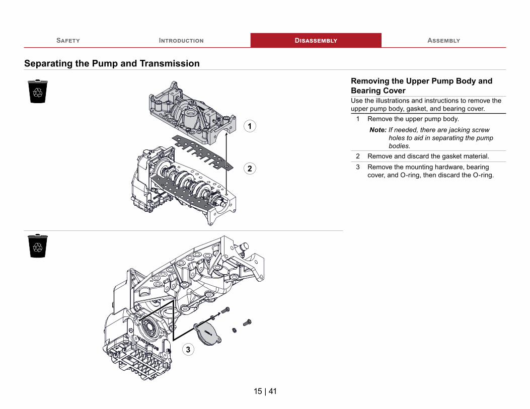
Removing the Upper Pump Body and Bearing CoverUse the illustrations and instructions to remove the upper pump body, gasket, and bearing cover.
1 Remove the upper pump body.Note: If needed, there are jacking screw
holes to aid in separating the pump bodies.
2 Remove and discard the gasket material.3 Remove the mounting hardware, bearing
cover, and O-ring, then discard the O-ring.

16 | 41
Safety Introduction Disassembly Assembly
Separating the Pump and Transmission
3
Removing the Lower Pump BodyUse the illustrations and instructions to remove the remaining transmission mounting hardware and lower pump body.
1 Remove the nuts and washers.2 Remove the threaded studs.3 Remove the lower pump body.
1
2

17 | 41
Safety Introduction Disassembly Assembly
Separating the Impeller Shaft Components
Removing the Impeller Shaft AssemblyUse the illustrations and instructions to remove the impeller shaft assembly.
1 Use locally sourced jacking screws (3/8-24 UNF with a minimum length of 1-1/2 inches) to separate the impeller shaft assembly and transmission case.
2 Remove the impeller shaft assembly from the transmission case.
1
2

18 | 41
Safety Introduction Disassembly Assembly
Removing the Impeller Shaft Components
1 4
2 5
3 6
Use the illustrations and instructions to disassemble the impeller shaft.
1 Remove the hardware and gland halves.2 Remove the packing rings and packing
housing. Discard the gasket.3 Remove the retaining ring.4 Use an arbor press to remove the wear
rings and impellers up to the interstage seal. Remove the key after removing the second impeller.Note: Make sure to note the orientation of
the impellers as you remove them for later in the assembly.
5 Remove the interstage seal.6 Remove the retaining ring.

19 | 41
Safety Introduction Disassembly Assembly
Removing the Impeller Shaft Components
7
8
10
9
11
Use the illustrations and instructions to disassemble the impeller shaft.
7 Use an arbor press to remove the wear rings and impellers up to the packing housing. Remove the key after removing the second impeller.
8 Discard the gasket, then remove the packing housing, packing rings, gland halves, and hardware.
9 Remove the flinger ring.10 Remove the hardware, bearing, driven gear,
bearing spacer, and key.11 Remove the bearing housing.

Notes

21 | 41
Safety Introduction Disassembly Assembly
Preparing to Assemble the Pump• Read and understand the instructions before assembling the pump.• Prepare a workspace suitable to accommodate and support the pump.• Gather the necessary tools and assembly aids.• Gather the necessary overhaul components, such as lubricant, bearings,
seals, and O-rings—only use equivalent components.• Understand that your configuration may require additional steps that are not
described in the illustrations or instructions to perform the assembly.• This equipment is intended to be assembled by a person or persons with the
basic knowledge of servicing similar equipment. Contact Waterous for more information.
Tools Required• Typical automotive mechanics hand tools.• Suitable arbor press.• Torque wrench capable of 200 ft-lb (271 N∙m).• Suitable support and lifting equipment.
Best Practices• Remove any dirt, sand, grease, or oil from the enclosure before you begin the
assembly. Surface debris can transfer into the pump interior and prematurely wear internal parts.
• Replace any gaskets and O-ring seals during the assembly.• Do not reuse the self-locking nuts.• Apply anti-seize to the self-locking nut threads before installation.
Optional EquipmentBe aware that the assembly instructions may include optional equipment not included in your application.
Assembling the Pump Components• Refer to the service parts list (SPL) for part identification.• The SPL specific to your application is determined by the following:
• The transmission drive method.• Whether the transmission drives a CAFS compressor.
Note: Documents specific to your application are available through the MyWaterous login at Waterousco.com by entering the serial number for your system. Depending on the application, the serial number for your equipment is located on the operator panel, pump, transmission, or some combination of the three.
• Use established industry practices to assemble the pump.• Tighten hardware to industry standard torque specification—unless otherwise
noted.• Make sure that you do not over-tighten plugs.• Install retaining rings with the rounded face toward the component you are
retaining.• Replace items such as O-rings, bearings, gaskets, oil seals, lubricants, and
locknuts with their equivalent.
Installing the PumpUse the information that you recorded when you removed the equipment to install it into the apparatus.
Understanding the IllustrationsThe assembly illustrations depict a typical application. Plugs, breathers, cooling hoses, and fittings are not illustrated, as they may be in a different location on your application. Refer to the SPL for your application to identify the various plug locations.

22 | 41
Safety Introduction Disassembly Assembly
Impeller Shaft Assembly

23 | 41
Safety Introduction Disassembly Assembly
Assembling the Bearing HousingUse the illustrations and instructions to assemble the bearing housing.
1 Apply grease to the bearing, then press it into the bearing housing.
2 Apply lubricant to the O-ring groove, then install the O-ring around the bearing housing.
3 Apply silicon sealant around the oil seal, then install it into the bearing housing.
1
3
2

24 | 41
Safety Introduction Disassembly Assembly
Assembling the Impeller ShaftUse the illustrations and instructions to assemble the impeller shaft.
1 Apply grease to the driven gear, then press it into the bearing.
2 Insert the key into the keyway. Apply grease to the shaft, then press the driven gear onto the shaft.
3 Install the washer and locknut onto the end of the shaft, then tighten the locknut.
4 Apply grease to the shaft, then install the bearing spacer onto the shaft.
5 Apply grease to the bearing, then press the bearing housing onto the shaft.
6 Install the flinger ring onto the shaft with the rounded edge toward the bearing housing.Note: The flinger ring should sit 1/16 inch
(1.5875 mm) from the edge of the inner shoulder.
1
2
3
4
5
6
100 ft-lb136 N∙m

25 | 41
Safety Introduction Disassembly Assembly
Assembling the Impeller Shaft
8
9 10
Use the illustrations and instructions to assemble the impeller shaft.
7 Install the gland halves, packing rings, packing housing, and gasket onto the shaft, then secure them with the hardware that you removed earlier.Refer to: "Installing and Tightening the Packing" on page 27.
8 Use an arbor press to install the wear rings and impellers onto the shaft in the reverse order you removed them. Insert the key into the keyway before installing the first impeller.
9 Install the retaining ring onto the shaft.10 Install the interstage seal onto the shaft.
7

26 | 41
Safety Introduction Disassembly Assembly
Assembling the Impeller Shaft
11 12
13
14
Use the illustrations and instructions to assemble the impeller shaft.
11 Use an arbor press to install the wear rings and impellers onto the shaft in the reverse order you removed them. Insert the key into the keyway before installing the first impeller.
12 Install the retaining ring onto the shaft.13 Install the gasket, packing housing, and
packing rings onto the shaft. Refer to: "Installing and Tightening the Packing" on page 27.
14 Install the gland halves onto the packing housing studs, then secure them with the hardware that you removed earlier. Refer to: "Installing and Tightening the Packing" on page 27.

27 | 41
Safety Introduction Disassembly Assembly
Installing and Tightening the Packing
1
2
Use the illustrations and instructions to install and tighten the packing.
1 When installing the packing rings, stagger the joints so that they are 90° apart.
2 To properly set the gland, do the following: • Install the nuts onto the packing housing
studs so that the milled slots are facing the gland.
• Finger-tighten the nuts, alternating between them to make sure that the gland stays level.
• Use a wrench to tighten the nuts one additional turn.

28 | 41
Safety Introduction Disassembly Assembly
Pump Body Assembly

29 | 41
Safety Introduction Disassembly Assembly
Installing the Impeller Shaft Assembly
1
Use the illustrations and instructions to install the impeller shaft assembly.
1 Apply grease to the bearing, then press the impeller shaft assembly into the transmission case.

30 | 41
Safety Introduction Disassembly Assembly
Installing the Lower Pump Body
1
2 3
Use the illustrations and instructions to secure the lower pump body to the transmission case.
1 Align the lower pump body with the impeller shaft assembly.
2 Use the threaded studs that you removed earlier to secure the lower pump body to the transmission case.
3 Loosely install the washers and nuts that you removed earlier onto the studs.

31 | 41
Safety Introduction Disassembly Assembly
Installing the Bearing Cover
1
2
Use the illustrations and instructions to install the bearing cover.
1 Apply lubricant to the O-ring groove, then install the O-ring around the bearing cover.
2 Use the hardware that you removed earlier to secure the bearing cover to the transmission case.

32 | 41
Safety Introduction Disassembly Assembly
Installing the Upper Pump Body
1
2
3
4
Use the illustrations and instructions to install the upper pump body.
1 Remove any remaining gasket material, then align the new gaskets with the lower pump body.
2 Align the upper pump body with the lower pump body.
3 Use the dowel pin that you removed earlier to connect the pump bodies.
4 Use the dowel pin that you removed earlier to connect the pump bodies.

33 | 41
Safety Introduction Disassembly Assembly
Installing the Upper Pump Body
2
1
Use the illustration and instructions to install the upper transmission mounting hardware.
1 Use the screws that you removed earlier to secure the upper pump body to the transmission case.
2 Loosely install the washers and nuts that you removed earlier onto the screw threads.

34 | 41
Safety Introduction Disassembly Assembly
Installing the Pump Body Hardware
1
2
3
Use the illustrations and instructions to install the upper and lower pump body hardware.
1 Use the hardware that you removed earlier to secure the upper pump body to the lower pump body.
2 Use the hardware that you removed earlier to secure the lower pump body to the upper pump body.
3 Tighten the transmission mounting hardware.
200 ft-lb271 N∙m
200 ft-lb271 N∙m

35 | 41
Safety Introduction Disassembly Assembly
Installing the Packing Housing Hardware
1
2
Use the illustrations and instructions to install the packing housing hardware.
1 Use the hardware that you removed earlier to secure the packing housing to the pump.
2 Use the hardware that you removed earlier to secure the packing housing to the pump.

36 | 41
Safety Introduction Disassembly Assembly
Installing the Flinger Ring and Bearing
1
2
Use the illustrations and instructions to install the flinger ring and bearing.
1 Install the flinger ring onto the shaft with the rounded edge toward the packing housing.Note: The flinger ring should sit flat against
the edge of the impeller shaft groove.2 Apply grease to the bearing, then press it onto
the shaft.

37 | 41
Safety Introduction Disassembly Assembly
Installing the Bearing Housing
1
2
Use the illustrations and instructions to install the bearing housing.
1 Align the bearing housing with the pump.2 Use the hardware that you removed earlier to
secure the bearing housing to the pump.

38 | 41
Safety Introduction Disassembly Assembly
Installing the Packing Cooler Hose
1
2
Use the illustrations and instructions to install the packing cooler hose.
1 Insert one end of the hose into the pump intake fitting.
2 Insert the other end of the hose into the upper pump body fitting.

39 | 41
Safety Introduction Disassembly Assembly
Testing After Installation
2
Use the illustration and instructions to adjust the packing after installing the pump into the apparatus. Note: Certain parts have been removed from the
illustration to provide a clear view of the equipment being tested.
1 Operate the pump at its maximum intended pressure for 10 minutes.
2 Observe the drip rate. Optimal leakage is 10 to 120 drops per minute. Maintaining this rate facilitates the cooling of the packing.
3 If the drip rate is too high, turn off the pump and gradually tighten the gland nuts, alternating between them to make sure that the gland stays level.
4 Operate the pump at its maximum intended pressure for 2 minutes. Observe the drip rate, then repeat the previous step until leakage is within the optimal range.
5 Repeat the process with the packing housing at the other end of the pump.
6 Make sure that you perform all tests required by the National Fire Protection Association.

Notes

Waterous Company125 Hardman Avenue SouthSouth Saint Paul, MN 55075
(651) 450-5000www.waterousco.com