cpx terminal - festo...cpx terminal modular, electric terminal type 50 cpx modules collective term...
TRANSCRIPT

Description Electronics
System manual
Installing andcommissioning CPXterminals
CPX terminal
Description526 446en 0902e [742939]


Contents and general safety instructions
I
Original en. . . . . . . . . . . . . . . . . . . . . . . . . . . . . . . . . . . . . . .
Edition en 0902e. . . . . . . . . . . . . . . . . . . . . . . . . . . . . . . . . .
Designation P.BE−CPX−SYS−EN. . . . . . . . . . . . . . . . . . . . . . . .
Order�no. 526 446. . . . . . . . . . . . . . . . . . . . . . . . . . . . . . . . .
E (Festo SE�&�Co. KG, D�73726 Esslingen, Germany, 2009) Internet: �http://www.festo.comE−mail: �[email protected]
The copying, distribution and utilisation of this document as well as the communication of its contents to others without expressed authorization is prohibited. Offenders will be held liable for compensation of damages. All rights are reserved, in particular the right to carry out patent, registered design or ornamental design registration.
Festo P.BE−CPX−SYS−EN en 0902e

Contents and general safety instructions
II Festo P.BE−CPX−SYS−EN en 0902e
HARAX®, INTEL®, Interbus®, Modbus®, MOTOROLA®, PROFIBUS®, Push−Pull®, TÜV® and VDE® are registeredtrademarks of the respective trademark owners in certaincountries.

Contents and general safety instructions
IIIFesto P.BE−CPX−SYS−EN en 0902e
Contents
Intended use VII . . . . . . . . . . . . . . . . . . . . . . . . . . . . . . . . . . . . . . . . . . . . . . . . . . . . . . . . . .
Range of application and certification VIII . . . . . . . . . . . . . . . . . . . . . . . . . . . . . . . . . . . . . . Target group IX . . . . . . . . . . . . . . . . . . . . . . . . . . . . . . . . . . . . . . . . . . . . . . . . . . . . . . . . . .
Service IX . . . . . . . . . . . . . . . . . . . . . . . . . . . . . . . . . . . . . . . . . . . . . . . . . . . . . . . . . . . . . . . Important user instructions X . . . . . . . . . . . . . . . . . . . . . . . . . . . . . . . . . . . . . . . . . . . . . .
Notes on the use of this manual XII . . . . . . . . . . . . . . . . . . . . . . . . . . . . . . . . . . . . . . . . . . .
1. Overview of components 1−1 . . . . . . . . . . . . . . . . . . . . . . . . . . . . . . . . . . . . . . . .
1.1 Structure of the CPX terminal 1−3 . . . . . . . . . . . . . . . . . . . . . . . . . . . . . . . . . . . . .
1.1.1 Mode of operation of the CPX terminal 1−7 . . . . . . . . . . . . . . . . . . . . . .
1.1.2 Structure of the electric CPX modules 1−17 . . . . . . . . . . . . . . . . . . . . . . .
1.1.3 The power supply concept of the CPX terminal 1−19 . . . . . . . . . . . . . . . .
1.2 Commissioning, diagnosis and operational functions 1−24 . . . . . . . . . . . . . . . . . .
2. Assembly 2−1 . . . . . . . . . . . . . . . . . . . . . . . . . . . . . . . . . . . . . . . . . . . . . . . . . . . . .
2.1 General instructions on assembly and dismantling 2−3 . . . . . . . . . . . . . . . . . . . .
2.2 Assembling electric modules with plastic interlinking blocks 2−6 . . . . . . . . . . . .
2.2.1 Replacing a complete module or interlinking block with tie rodinterlinking 2−7 . . . . . . . . . . . . . . . . . . . . . . . . . . . . . . . . . . . . . . . . . . . . .
2.2.2 Increasing or reducing the number of electric modules 2−10 . . . . . . . . .
2.2.3 Fitting the right−hand end plates with Midi/Maxi valves 2−15 . . . . . . . . .
2.3 Assembling electric modules with metal interlinking blocks 2−17 . . . . . . . . . . . . .
2.3.1 Replacing a complete module or interlinking block 2−18 . . . . . . . . . . . .
2.4 Fitting the CPX terminal 2−21 . . . . . . . . . . . . . . . . . . . . . . . . . . . . . . . . . . . . . . . . . .
2.4.1 Fitting CPX terminals without pneumatics onto a H−rail 2−21 . . . . . . . . .
2.4.2 Fitting CPX terminals with pneumatics onto an H−rail 2−22 . . . . . . . . . . .
2.4.3 Fitting CPX terminals with Midi/Maxi pneumatics onto an H−rail 2−26 . .
2.4.4 Wall mounting 2−29 . . . . . . . . . . . . . . . . . . . . . . . . . . . . . . . . . . . . . . . . . .
3. Installation 3−1 . . . . . . . . . . . . . . . . . . . . . . . . . . . . . . . . . . . . . . . . . . . . . . . . . . .
3.1 General installation instructions 3−3 . . . . . . . . . . . . . . . . . . . . . . . . . . . . . . . . . . .
3.1.1 Connecting cable 3−3 . . . . . . . . . . . . . . . . . . . . . . . . . . . . . . . . . . . . . . . .

Contents and general safety instructions
IV Festo P.BE−CPX−SYS−EN en 0902e
3.1.2 Configuration of the CPX bus node 3−6 . . . . . . . . . . . . . . . . . . . . . . . . .
3.1.3 Configuration of the pneumatics 3−7 . . . . . . . . . . . . . . . . . . . . . . . . . . .
3.1.4 Selecting the power supply unit 3−8 . . . . . . . . . . . . . . . . . . . . . . . . . . . .
3.1.5 Power supply of the CPX terminal 3−12 . . . . . . . . . . . . . . . . . . . . . . . . . .
4. Commissioning 4−1 . . . . . . . . . . . . . . . . . . . . . . . . . . . . . . . . . . . . . . . . . . . . . . . .
4.1 Procedure for commissioning 4−3 . . . . . . . . . . . . . . . . . . . . . . . . . . . . . . . . . . . . .
4.2 Preparing the CPX terminal for commissioning 4−4 . . . . . . . . . . . . . . . . . . . . . . .
4.2.1 Parameter types 4−6 . . . . . . . . . . . . . . . . . . . . . . . . . . . . . . . . . . . . . . . .
4.2.2 Possibilities of parametrisation 4−9 . . . . . . . . . . . . . . . . . . . . . . . . . . . .
4.3 Start−up behaviour of the CPX terminal 4−10 . . . . . . . . . . . . . . . . . . . . . . . . . . . . .
5. Diagnostics and error handling 5−1 . . . . . . . . . . . . . . . . . . . . . . . . . . . . . . . . . . .
5.1 General notes on diagnosis 5−3 . . . . . . . . . . . . . . . . . . . . . . . . . . . . . . . . . . . . . . .
5.1.1 On the spot diagnosis with LEDs 5−5 . . . . . . . . . . . . . . . . . . . . . . . . . . .
5.1.2 CPX−specific LEDs 5−6 . . . . . . . . . . . . . . . . . . . . . . . . . . . . . . . . . . . . . . .
5.2 Diagnosis via status bits or the I/O diagnostic interface 5−11 . . . . . . . . . . . . . . . .
5.2.1 Structure of the status bits 5−12 . . . . . . . . . . . . . . . . . . . . . . . . . . . . . . . .
5.2.2 The I/O diagnostic interface 5−14 . . . . . . . . . . . . . . . . . . . . . . . . . . . . . . .
5.2.3 Error numbers 5−19 . . . . . . . . . . . . . . . . . . . . . . . . . . . . . . . . . . . . . . . . . .
A. Technical appendix A−1 . . . . . . . . . . . . . . . . . . . . . . . . . . . . . . . . . . . . . . . . . . . . .
A.1 Technical data A−3 . . . . . . . . . . . . . . . . . . . . . . . . . . . . . . . . . . . . . . . . . . . . . . . . . .
A.2 Cable length and cross−sectional area A−7 . . . . . . . . . . . . . . . . . . . . . . . . . . . . . .
B. Parameters and data of the CPX terminal B−1 . . . . . . . . . . . . . . . . . . . . . . . . . . .
B.1 Access to internal parameters and data B−3 . . . . . . . . . . . . . . . . . . . . . . . . . . . . .
B.2 Description of the parameters and data B−4 . . . . . . . . . . . . . . . . . . . . . . . . . . . . .
B.2.1 Overview of the function numbers B−5 . . . . . . . . . . . . . . . . . . . . . . . . . .
B.2.2 System parameters B−8 . . . . . . . . . . . . . . . . . . . . . . . . . . . . . . . . . . . . . .
B.2.3 Module parameters B−15 . . . . . . . . . . . . . . . . . . . . . . . . . . . . . . . . . . . . . .
B.2.4 Diagnostic memory parameters B−23 . . . . . . . . . . . . . . . . . . . . . . . . . . . .
B.2.5 Diagnostic memory data B−29 . . . . . . . . . . . . . . . . . . . . . . . . . . . . . . . . . .

Contents and general safety instructions
VFesto P.BE−CPX−SYS−EN en 0902e
B.2.6 System diagnostic data B−32 . . . . . . . . . . . . . . . . . . . . . . . . . . . . . . . . . . .
B.2.7 Module diagnostic data B−34 . . . . . . . . . . . . . . . . . . . . . . . . . . . . . . . . . .
B.2.8 System data B−36 . . . . . . . . . . . . . . . . . . . . . . . . . . . . . . . . . . . . . . . . . . . .
B.2.9 Module data B−42 . . . . . . . . . . . . . . . . . . . . . . . . . . . . . . . . . . . . . . . . . . . .
C. General information on parametrisation C−1 . . . . . . . . . . . . . . . . . . . . . . . . . . .
C.1 Input debounce time C−3 . . . . . . . . . . . . . . . . . . . . . . . . . . . . . . . . . . . . . . . . . . . .
C.2 Signal extension C−5 . . . . . . . . . . . . . . . . . . . . . . . . . . . . . . . . . . . . . . . . . . . . . . . .
C.3 Influence of signal states C−8 . . . . . . . . . . . . . . . . . . . . . . . . . . . . . . . . . . . . . . . . .
C.3.1 Force C−11 . . . . . . . . . . . . . . . . . . . . . . . . . . . . . . . . . . . . . . . . . . . . . . . . . .
C.3.2 Signal status in the event of a fault (Fail safe) C−15 . . . . . . . . . . . . . . . . .
C.3.3 Signal status in Idle status (Idle mode) C−18 . . . . . . . . . . . . . . . . . . . . . .
C.4 Diagnostic memory C−20 . . . . . . . . . . . . . . . . . . . . . . . . . . . . . . . . . . . . . . . . . . . . .
C.5 Monitoring errors C−23 . . . . . . . . . . . . . . . . . . . . . . . . . . . . . . . . . . . . . . . . . . . . . . .
D. Index D−1 . . . . . . . . . . . . . . . . . . . . . . . . . . . . . . . . . . . . . . . . . . . . . . . . . . . . . . . . .

Contents and general safety instructions
VI Festo P.BE−CPX−SYS−EN en 0902e

Contents and general safety instructions
VIIFesto P.BE−CPX−SYS−EN en 0902e
Intended use
CPX terminals are intended for installation in machines orautomation systems. Depending on the CPX bus node used,they can be connected to a special field bus system and serveto interrogate sensor signals and to control pneumatic andelectric actuators.
The individual CPX modules of the CPX terminal are docu�mented in specific manuals. The safety instructions listed inthe manuals must always be observed and the relevant CPXmodule must only be used as intended. CPX modules andcables are only to be used as follows:
� Only in an industrial environment
� As intended
� In original status without unauthorised modifications.Only the conversions or modifications described in thedocumentation supplied with the product are permitted.
� In perfect technical condition.
When used together with commercially available compo�nents, such as sensors and actuators, the specified limits forpressures, temperatures, electrical data, torques etc. must beobserved. Also observe the standards specified in the rele�vant chapters, as well as national and local laws and technicalregulations.

Contents and general safety instructions
VIII Festo P.BE−CPX−SYS−EN en 0902e
Range of application and certification
The product fulfils the requirements of the EU directives andis marked with the CE marking symbol.
Standards and test values, which the product must complywith and fulfil, can be found in the section �Technical data".The product−relevant EU directive can be found in the decla�ration of conformance.
Certain configurations of the product have been certified byUnderwriters Laboratories Inc. (UL) for the USA and Canada.These configurations are marked as follows:
UL�Recognized Component Mark for Canada and the UnitedStates
NoteObserve the following if the UL requirements are to becomplied with in your application:
� Rules for observing the UL certification can be found inthe separate UL−specific documentation. The relevanttechnical specifications listed there also apply here.
� The technical specifications in this documentation mayshow different values.

Contents and general safety instructions
IXFesto P.BE−CPX−SYS−EN en 0902e
Target group
This manual is directed exclusively at technicians trained incontrol and automation technology.
Service
Please consult your local Festo repair service if you have anytechnical problems.

Contents and general safety instructions
X Festo P.BE−CPX−SYS−EN en 0902e
Important user instructions
Danger categories
This manual contains instructions on the possible dangerswhich can occur if the product is not used correctly. Theseinstructions are marked (Warning, Caution, etc), printed ona�shaded background and marked additionally with a picto�gram. A distinction is made between the following dangerwarnings:
Warning... means that failure to observe this instruction may resultin serious personal injury or material damage.
Caution... means that failure to observe this instruction may resultin personal injury or material damage.
Note... means that failure to observe this instruction may resultin material damage.
The following pictogram marks passages in the text whichdescribe activities with electrostatically sensitive devices:
Electrostatically sensitive devices: inappropriate handling canresult in damage to components.

Contents and general safety instructions
XIFesto P.BE−CPX−SYS−EN en 0902e
Identification of specific information
The following pictograms designate texts that contain specialinformation.
Pictograms
Information:Recommendations, tips and references to other sources ofinformation
Accessories:Information about necessary or useful accessories for theFesto product.
Environment:Information on the environmentally friendly use of Festo products.
Text designations
· Bullet points indicate activities that may be carried out inany order.
1. Numerals denote activities which must be carried out inthe numerical order specified.
� Arrowheads indicate general lists.

Contents and general safety instructions
XII Festo P.BE−CPX−SYS−EN en 0902e
Notes on the use of this manual
This manual contains general basic information on the me�thod of operation, on fitting, installing and commissioningCPX terminals.
Special information on commissioning, parameterising anddiagnosing a CPX terminal with the CPX bus node you areusing can be found in the appropriate manual for the CPX busnode.
Information about further CPX modules can be found in themanual for the relevant module. An overview is provided inTable�0/1.
Conventions
The parameters and data of the CPX terminal are described inAppendix B.2. These appear in English on the handheld typeCPX−MMI−1.

Contents and general safety instructions
XIIIFesto P.BE−CPX−SYS−EN en 0902e
Type Title Description
DescriptionElectronics
�System description"Type P.BE−CPX−SYS−...
Overview of structure, components and modeof operation of CPX terminals;installation and commissioning instructions aswell as basic principles of parametrisation
�CPX bus node"Type P.BE−CPX−FB...
Instructions on assembly, installation, commis�sioning and diagnostics of the relevant busnodes
�CPX I/O modules"Type P.BE−CPX−EA−...
Notes on connections and instructions on fit�ting, installing and commissioning input andoutput modules of type CPX−.... and the MPA,CPA and Midi/Maxi pneumatic interfaces
�CPX analogue I/O mo�dules"Type P.BE−CPX−AX−...
Notes about connection types and instructionsfor fitting, installing and commissioning CPXanalogue I/O modules
"CPX−CP interface"Type P.BE−CPX−CP−..
Instructions on fitting, installing, commissio�ning and diagnosing CP systems with the CP interface type CPX−CP−4−FB
�Handheld"Type P.BE−CPX−MMI−1−..
Instructions for commissioning and diagnosingCPX terminals with the handheld type�CPX−MMI−1
�MPA electronics modu�les"Type P.BE−MPA−ELEKTRONIK−...
Instructions on assembly, installation, commis�sioning and diagnostics of the MPA pneumaticand electronic modules.
ManualElectronics
�CPX−FEC"Type P.BE−CPX−FEC−...
Instructions for fitting, installing, commissioning and diagnosing the CPX Front End Controller.
Software package
�FST" Programming in statement list and ladder diagram for the FEC
Table�0/1: Descriptions for the CPX terminal � part 1

Contents and general safety instructions
XIV Festo P.BE−CPX−SYS−EN en 0902e
Type Title Description
DescriptionPneumatics
�Valve terminals withMPA pneumatics"Type P.BE−MPA−...
Instructions for fitting, installing, commissio�ning, maintaining and converting the MPApneumatics
�Valve terminals withCPA pneumatics"Type P.BE−CPA−...
Instructions for fitting, installing, commissio�ning, maintaining and converting the CPApneumatics (type 12)
�Valve terminals withMidi/Maxi pneumatics"Type P.BE−Midi/Maxi−03−...
Instructions for fitting, installing, commissio�ning, maintaining and converting the Midi/Maxi pneumatics (type 03)
Table�0/2: Descriptions for the CPX terminal � part 2

Contents and general safety instructions
XVFesto P.BE−CPX−SYS−EN en 0902e
Term/abbreviation Meaning
Connection block Exchangeable housing upper part of modules with connection technology.
CP Compact Performance
CPX bus node Provides the connection to specific fieldbuses. Transmits control signalsto the connected modules and monitors their ability to function.
CPX terminal Modular, electric terminal type 50
CPX modules Collective term for the various modules which can be integrated in a CPXterminal.
DIL switch Dual−in−line switches consist of several logic elements with which settingscan be made.
Fieldbus Data bus via which the CPX modules communicate with each other andare supplied with the necessary operating voltage.
Function modules Function modules are also known as technology modules (e.g. CPX−CPinterface)
Input module CPX input module
Interlinking block Lower part of the housing of a module or block for interlinking the moduleelectrically with the terminal
I Digital input
I/O diagnostic interface The I/O diagnostic interface is a bus−independent diagnostic interface atI/O level, permitting access to internal data of the CPX terminal.
I/O modules Common term for the CPX modules which provide digital inputs and out�puts (CPX input modules and CPX output modules).
I/Os Digital inputs and outputs
NBR Nitrile butadiene rubber, material for seals
O Digital output
Output module CPX output module
PLC/IPC Programmable logic controller/industrial PC
Pneumatic interface The pneumatic interface is the interface between the modular electricalperipherals and the pneumatics.

Contents and general safety instructions
XVI Festo P.BE−CPX−SYS−EN en 0902e
Term/abbreviation Meaning
Status bits Internal inputs that supply coded common diagnostic messages
Technology modules Function modules are also known as technology modules (e.g. CPX−CPinterface)
Table�0/3: Product−specific terms and abbreviations

Overview of components
1−1Festo P.BE−CPX−SYS−EN en 0902e
Chapter 1

1. Overview of components
1−2 Festo P.BE−CPX−SYS−EN en 0902e
Contents
1. Overview of components 1−1 . . . . . . . . . . . . . . . . . . . . . . . . . . . . . . . . . . . . . . . .
1.1 Structure of the CPX terminal 1−3 . . . . . . . . . . . . . . . . . . . . . . . . . . . . . . . . . . . . .
1.1.1 Mode of operation of the CPX terminal 1−7 . . . . . . . . . . . . . . . . . . . . . .
1.1.2 Structure of the electric CPX modules 1−17 . . . . . . . . . . . . . . . . . . . . . . .
1.1.3 The power supply concept of the CPX terminal 1−19 . . . . . . . . . . . . . . . .
1.2 Commissioning, diagnosis and operational functions 1−24 . . . . . . . . . . . . . . . . . .

1. Overview of components
1−3Festo P.BE−CPX−SYS−EN en 0902e
1.1 Structure of the CPX terminal
CPX terminals consist of electric and pneumatic modules forcontrolling pneumatic actuators and low−current consumingelectric devices (further valves, bulbs, etc.). They are usuallyplaced decentrally directly on the machine or system.
Design variants CPX terminals are available in plastic version (type CPX−...)and in metal version (type CPX−M−...) with various differentfunctions. They can be fitted with different electric and pneu�matic modules (valves) in accordance with the customer’swishes. The equipment fitted on the CPX terminal in this man�ual may therefore differ from the equipment you are using.
1
2
1 Electric modules (electric side) 2 Pneumatic modules (pneumatic side);optional
Fig.�1/1: Structure of a CPX terminal with CPA pneumatics (example in plastic version)

1. Overview of components
1−4 Festo P.BE−CPX−SYS−EN en 0902e
Fieldbus connection CPX terminals with fieldbus connection permit communica�tion with remotely−situated higher−order control systems.
CPX terminals are constructed on a modular basis and canconsist of the following modules, for example:
Modules Brief description
CPX bus node for connecting tohigher−order control systems via thefieldbus;Connections depend on the design ofthe CPX bus node
CPX Front End Controller for control�ling pneumatic and electric actua�tors; communication via Ethernet(web server, e−mail, Modbus TCP,EasyIP etc.)
CPX I/O modules for evaluating pro�cess signals;Selectable connection technology(M12 connections here)
CPX−CP interface for connecting de�centrally arranged CP I/O modulesand CP valve terminals (technologymodule)
Tab.�1/1: Electrical modules of a CPX terminal (examples inplastic version)

1. Overview of components
1−5Festo P.BE−CPX−SYS−EN en 0902e
Modules Brief description
Pneumatic interface for connectingthe modular electrical peripherals oftype�50 (CPX) to valve terminals oftype�32 (MPA)
Pneumatic interface for connectingthe modular electrical peripherals oftype�50 (CPX) to VTSA/ISO valves(type�44)
Pneumatic interface for connectingthe modular electrical peripherytype�50 (CPX) to valve terminals oftype�03 (Midi/Maxi).
Pneumatic interface for connectingthe modular electrical peripherals oftype�50 (CPX) to valve terminals oftype�12 (CPA)
Tab.�1/2: Pneumatic interface modules for CPX terminals

1. Overview of components
1−6 Festo P.BE−CPX−SYS−EN en 0902e
Modules Brief description
MPA
VTSA
Midi/Maxi
ÌÌ
ÌÌÌÌ
ÌÌÌÌÌÌÌÌÌÌÌÌÌÌÌÌÌÌÌÌ
ÌÌÌÌ
CPA
Tab.�1/3: Valve terminal pneumatics for CPX terminals
The electric and pneumatic side of the CPX terminal can beadapted to various requirements. The electric side can befitted with various electric CPX modules, e.g.�a CPX bus node,digital and analogue CPX I/O modules etc. (see Tab.�1/1).

1. Overview of components
1−7Festo P.BE−CPX−SYS−EN en 0902e
The pneumatic side can be fitted with pneumatics of typeMPA, VTSA, Midi/Maxi or CPA (see Tab.�1/3). Different sizes of valves are possible here. Pneumatic modules are not abso�lutely necessary. CPX terminals can consist exclusively ofelectric modules. If pneumatic modules are to be used, thepneumatic interface appropriate to the pneumatics in ques�tion is required (see Tab.�1/2).
1.1.1 Mode of operation of the CPX terminal
1 Fieldbusincoming
2 Fieldbuscontinuing
3 Compressed airsupply
4 Supply air (2/4)
5 CPX bus node
1 2
3
4
5
Fig.�1/2: Function overview of CPX terminal (here with MPA pneumatics)
1. Overview of components
1−8 Festo P.BE−CPX−SYS−EN en 0902e
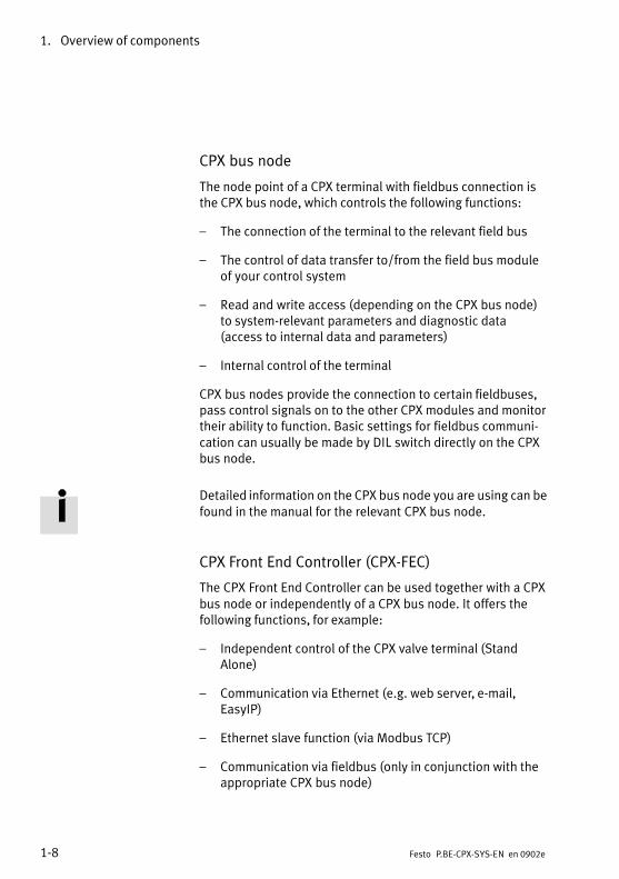
CPX bus node
The node point of a CPX terminal with fieldbus connection isthe CPX bus node, which controls the following functions:
� The connection of the terminal to the relevant field bus
� The control of data transfer to/from the field bus moduleof your control system
� Read and write access (depending on the CPX bus node)to system−relevant parameters and diagnostic data (access to internal data and parameters)
� Internal control of the terminal
CPX bus nodes provide the connection to certain fieldbuses,pass control signals on to the other CPX modules and monitortheir ability to function. Basic settings for fieldbus communi�cation can usually be made by DIL switch directly on the CPXbus node.
Detailed information on the CPX bus node you are using can befound in the manual for the relevant CPX bus node.
CPX Front End Controller (CPX−FEC)
The CPX Front End Controller can be used together with a CPXbus node or independently of a CPX bus node. It offers thefollowing functions, for example:
� Independent control of the CPX valve terminal (StandAlone)
� Communication via Ethernet (e.g. web server, e−mail,EasyIP)
� Ethernet slave function (via Modbus TCP)
� Communication via fieldbus (only in conjunction with theappropriate CPX bus node)

1. Overview of components
1−9Festo P.BE−CPX−SYS−EN en 0902e
CPX I/O modules
Processing signals can be evaluated with the CPX I/O mod�ules. Input modules provide inputs for connecting sensorsand enable cylinder positions to be scanned, for example.Output modules provide universally usable electric outputsfor controlling low−current consuming devices (further valves,bulbs, etc.).
NoteIncluding the CPX bus node, a maximum of�10 electric CPXmodules plus a pneumatic interface are permitted on theelectric side.
The CPX I/O modules have various types of connections. Theconnections are on a sub−base which can be removed fromthe module. This offers the following advantages:
� The CPX terminal can be fitted with the desired con�nections. It can be adapted easily to various applica�tions and operating conditions.
� When servicing is required, the electronics of the I/Omodules can be replaced without the need to dis�mantle the CPX terminal, or to loosen individual con�nections on the I/O modules.
The following types of connection can be used:
� M12 connection, 5− or 8−pin
� M8 connection, 3− or 4−pin
� Terminal strips, 16−pin
� Sub−D connection, 25−pin
� HARAX connection, 4−pin
Further information on the CPX I/O modules can be found in themanual �CPX I/O modules", type P. BE−CPX−EA−...

1. Overview of components
1−10 Festo P.BE−CPX−SYS−EN en 0902e
CPX−CP interface
The CPX−CP interface serves for connecting decentrally ar�ranged CP modules (CP valve terminals and CP I/O modules).It transmits control signals to the connected CP modules andmonitors their ability to function. Maximum 128 external I/Osare possible per CPX−CP interface.
Detailed information on the CPX−CP interface can be found inthe manual for the CPX−CP interface type P. BE−CPX−CP−...
Pneumatic interface
If the CPX terminal is to be fitted with valves, a pneumaticinterface will be required (see Tab.�1/2). The pneumatic inter�face is the interface between the electric and pneumatic pe�ripherals. It forms the mechanical connection between thepneumatic and electric modules and transmits the electricsignals.
The CPX pneumatic interface is mounted on the right−handside of the last electric module. Pneumatic interfaces can beused for e.g.:
� Pneumatics of type MPA (maximum 128�solenoid coils)
� Pneumatics of type VTSA (maximum 32�solenoid coils)
� Pneumatics of type Midi/Maxi (maximum 26�solenoidcoils)
� Pneumatics of type CPA (maximum 22�solenoid coils)

1. Overview of components
1−11Festo P.BE−CPX−SYS−EN en 0902e
Pneumatic interface forMPA pneumatics
The pneumatic interface for MPA pneumatics provides themechanical and electrical connection to the MPA pneumaticmodules. Therefore, from the point of view of the CPX termi�nal, the MPA pneumatic interface does not count as an elec�tric module. Instead, the individual MPA pneumatic moduleseach represent an electric module with digital outputs fortriggering the integrated valves.
Pneumatic interfaces forVTSA pneumatics, Midi/Maxi pneumatics or CPA pneumatics
From a technical point of view, the pneumatic interfaces for VTSA pneumatics, Midi/Maxi pneumatics or CPA pneu�matics represent electrical modules with a variable (configu�rable) number of digital outputs for activating the integratedvalves.
Detailed information on the CPX pneumatic interfaces andMPA pneumatic modules can be found in the manual for theCPX I/O modules of type P. BE−CPX−EA−...
Valve terminal pneumatics
The valve terminal pneumatics provide the following:
� Common channels for supply and exhaust air
� Electric signals for all valve solenoid coils
Working lines 2 and 4 are provided for each valve position onthe individual pneumatic modules. The valves are suppliedwith compressed air via the common channels or via specialsupply modules. Both the air and auxiliary pilot air from thevalves are also exhausted via these common channels.Further modules for pressure supply are also available, e.g. in order to permit work to be carried out with differentwork pressures.

1. Overview of components
1−12 Festo P.BE−CPX−SYS−EN en 0902e
CPX terminals without pneumatics
CPX terminals without pneumatic modules possess an endplate instead of the pneumatic interface. This design providesdigital and analogue inputs and outputs on the relevant fieldbus. A maximum of 10 electric modules (including theCPX bus node) are permitted on a CPX terminal.
1 CPX bus node
2 I/O modules
3 Right end plate
4 Left end plate
X 1
X 2
X 3
X 4
X 1
X 2
X 3
X 4
X 1
X 2
X 3
X 4
1 2
34
Fig.�1/3: CPX terminal as fieldbus I/O slave

1. Overview of components
1−13Festo P.BE−CPX−SYS−EN en 0902e
Valve terminal pneumatics of type MPA
MPA pneumatics consist of serially linked MPA pneumaticmodules. From a technical viewpoint, the MPA pneumaticmodules in a CPX terminal represent digital output modulesfor controlling the integrated valves (valve solenoid coils). The pneumatic interface for MPA pneumatics provides themechanical and electrical connection to the MPA pneumaticmodules.
CPX terminals with MPA pneumatics can be expanded as fol�lows:
CPX terminal with MPA pneumatics Number of valve positions1)
Load voltage supply for the valves via ...� CPX terminal 2)
� CPX terminal and electric supply plate (MPA) 3)
MPA14, 8, 12 ... 324, 8, 12 ... 64
MPA22, 4, 6 ... 162, 4, 6 ... 32
1) Two solenoid coils can be controlled per valve position.2) A max. of 64 solenoid coils can be supplied.3) A max. of 128 solenoid coils can be supplied.
Tab.�1/4: Number of valve positions of the CPX terminal with MPA pneumatics
1 Pneumaticinterface for MPApneumatics
2 Valve terminalpneumatics oftype MPA
3 Right end plate
4 MPA1 pneumaticmodule
5 Supply plate
1 2
3
454
Fig.�1/4: CPX terminal with MPA pneumatics

1. Overview of components
1−14 Festo P.BE−CPX−SYS−EN en 0902e
Valve terminal pneumatics of type VTSA
Valve terminal pneumatics of type VTSA are built up on amodular basis and can be equipped with combinations ofvalves in the following sizes:
� Size�02 (to ISO�15407−2), 18�mm
� Size�01 (to ISO�15407−2), 26�mm
� Size�1 (to ISO�5599−2), 42�mm
In this way adaptation to the requirements of the machine orsystem can also be made on the pneumatic side.
The valve positions can be configured individually (sizes 18and 26�mm) or in steps of two (size 42�mm) up to a maximumof 32 valve positions. Unused valve positions can be sealedwith blanking plates.
1 Pneumaticinterfaces forVTSA pneumatics
2 Valve terminalpneumatics oftype VTSA
3 Right end plate
4 Valves of size18�mm
5 Supply plate
6 Valves of size26�mm
1 2
3
456
Fig.�1/5: CPX terminal with VTSA pneumatics

1. Overview of components
1−15Festo P.BE−CPX−SYS−EN en 0902e
Valve terminal pneumatics of type Midi/Maxi
Valve terminal pneumatics of type Midi/Maxi are also built upon a modular basis. These valve terminal pneumatics consistof MIDI and MAXI valves. Valves of both sizes can be oper�ated together on a CPX terminal. In this way adaptation to therequirements of the machine or system can also be made onthe pneumatic side.
The valve positions can be configured in steps of two from 2to 26 valve locations. Unused valve positions can be sealedwith blanking plates.
1 Pneumaticinterface forMidi/Maxi
2 Valve terminalpneumatics oftype Midi/Maxi
3 Right end plate
4 Maxi valves
5 Midi valves
1 2
3
45
Fig.�1/6: CPX terminal with Midi/Maxi pneumatics

1. Overview of components
1−16 Festo P.BE−CPX−SYS−EN en 0902e
Valve terminal pneumatics of type CPA
Valve terminal pneumatics of type CPA are distinguished bycompact exterior dimensions in proportion to the high flowrates. They have replaceable valve plates that are mountedon sub−bases. The sub−bases are connected mechanically bytie rods and have an end plate at the side. Valve plates areavailable in different sizes.
The valve positions can be configured in single steps from 2to 22�valve positions.
1 Pneumaticinterface for CPA(here CPA10)
2 Valve terminalpneumatics oftype CPA
3 End plates
4 Valve plates (hereCPA10)
ÌÌÌÌÌÌÌÌ
ÌÌÌÌÌÌÌÌ
1 2
343
Fig.�1/7: CPX terminal with CPA pneumatics
Further information on the pneumatics of your CPX valve ter�minal can be found in the appropriate Pneumatics Manual.

1. Overview of components
1−17Festo P.BE−CPX−SYS−EN en 0902e
1.1.2 Structure of the electric CPX modules
An electric CPX module always consists of:
� An interlinking block (see section�1.1.3 for variants)
� An electronics module
� A connection block (selectable for I/O modules)
1
2
3
1 Sub−base (selectable housing upperpart)
2 Electronics module
3 Interlinking block (selectable housinglower part)
Fig.�1/8: Structure of the CPX modules (example)
Connection block The upper part of the housing selected for the CPX I/O mod�ules is called the connection block. Connection blocks providethe necessary connections for sensors and actuators. In thisway, the CPX terminal offers a high degree of flexibility withregard to adaptation to different applications and operatingconditions.

1. Overview of components
1−18 Festo P.BE−CPX−SYS−EN en 0902e
Electronic module The electronic module contains the electronic components.It�is connected to the interlinking block and to the connectionblock by means of electric plug connectors. Many electronicsmodules can be combined with various connection blocks.
In the case of the CPX bus node, the connection technology isan integral part of the module; in other words, the connectionblock and the electronics module form a single unit.
Interlinking block The lower part of the housing of the electric modules is calledthe interlinking block. Interlinking blocks serve for the electri�cal and mechanical linking of the modules. They can providea�connection for supplying the operating voltage and/or loadvoltage and transmit the operating and load voltages to theneighbouring modules (see section�1.1.3). In the plastic ver�sion of the interlinking blocks, the mechanical link betweenthe electric modules is made via tie rods (see section�2.2.1).Interlinking blocks in the metal version are bolted togetherindividually (see section�2.3).
You can replace electronics modules with connection blocksduring servicing without the need to dismantle the CPX ter�minal or loosen individual connections. Instead the entireconnection block is removed, the electronics module is re�placed and the connection block is placed into position again(see manual for the �CPX I/O modules", type P. BE−CPX−EA−...).

1. Overview of components
1−19Festo P.BE−CPX−SYS−EN en 0902e
NoteWith a combination of connection blocks and interlinkingblocks with metal on plastic or plastic on metal, always usethe appropriate screws for the interlinking block (seewww.festo.com\catalogue):
� With plastic interlinking block: thread−cutting screws
� With metal interlinking blocks: screws with metric thread
1.1.3 The power supply concept of the CPX terminal
The operating and load voltages for the CPX terminal are sup�plied via the interlinking blocks (see Tab.�1/5 and Tab.�1/6).These conduct the operating and load voltages to the neigh�bouring modules.
Interlinking blocks are available in various housing designsand with alternative connections:
Type of plug con�t
Numberf i
Interlinking block innector of pins plastic
versionmetal version
M18 4−pin · �
7/8" 4−pin · �
5−pin · ·
Push pull 5−pin � ·
· Available� Not available
Interlinking blocks with 5−pin plug connectors enable separ�ate electrical circuits for the operating voltage for electronics/sensors and the load voltage for outputs/valves.

1. Overview of components
1−20 Festo P.BE−CPX−SYS−EN en 0902e
Interlinking blocks are available in plastic and metal designsand with various alternative connections:
� M18 plug, 4−pin
� 7/8" plug, 4−pin
� 7/8" plug, 5−pin
� Push−pull plug, 5−pin
The pin allocation for all alternative connections is describedin Tab.�3/4 and in the package insert for the interlinkingblocks with supply.
Section�3.1.4 describes the criteria for selecting an appropri�ate power supply unit, and calculation tables for designingthe electrical circuits.

1. Overview of components
1−21Festo P.BE−CPX−SYS−EN en 0902e
Interlinking blocksM18 or 7/8"
Description
Types CPX−(M−)GE−EV−S...Interlinking blocks in plastic and metal version with system supply, ofwhich precisely one of each must be available for each CPX terminal.� Operating voltage for internal electronics and for the internal electronics
of the CP modules connected to the CPX−CP interface� Sensor supply for internal input modules and for the CP input modules
connected to the CPX−CP interface� Load voltage supply for internal output modules and valves� Load voltage supply for the CP modules connected to the CPX−CP inter�
face
Types CPX−(M−)GE−EV−Z... 1)
Interlinking blocks in plastic and metal version with additional powersupply for electrical outputs� Load voltage supply for the output module inserted and for the
subsequent output modules inserted to the right.
Type CPX−GE−EV−V... 1) 2)
Interlinking blocks with additional power supply for valves� Load voltage supply for the pneumatic modules/valves inserted
subsequently to the right.� Load voltage supply for CP modules which are connected to the fitted
CPX−CP interface and to those CPX−CP interfaces subsequently fitted tothe right
1) Optional − depends on the current consumption of the CPX modules and the connected compo�nents.
2) Not available for all alternative connections.
Tab.�1/5: Interlinking blocks with supply (M18 or 7/8")

1. Overview of components
1−22 Festo P.BE−CPX−SYS−EN en 0902e
Interlinking blocksPush pull
Description
Type CPX−M−GE−EV−S−PP−5POLInterlinking blocks with push−pull system supply, of which precisely one ofeach must be available for each CPX terminal.� Operating voltage for internal electronics and for the internal electronics
of the CP modules connected to the CPX−CP interface� Sensor supply for internal input modules and for the CP input modules
connected to the CPX−CP interface� Load voltage supply for internal output modules and valves� Load voltage supply for the CP modules connected to the CPX−CP inter�
face
Type CPX−M−GE−EV−S−PP−5POL 1)
Interlinking blocks with push−pull forwarding function for supplying powerto subsequent equipment� Must be placed immediately to the right of the system power supply.� Only one interlinking block with forwarding function may be used for
each CPX terminal and� The forwarding function must not be combined with additional power
supplies.� Interlinking blocks with a push−pull forwarding function are identically
constructed to those with with a push−pull system power supply. It istherefore necessary to provide external protection in both cases (seesection�3.1.4)
Type CPX−M−GE−EV−Z−PP−5POL 1)
Interlinking blocks in metal version with push−pull additional power supplyfor electrical outputs� Must be placed to the right of the system power supply.� The additional power supply must not be combined with the forwarding
function.� Load voltage supply for the output module fitted and for the subsequent
output modules fitted to the right.
1) Optional − depends on the current consumption of the CPX modules and the connected compo�nents.
Tab.�1/6: Interlinking blocks with supply (push−pull)

1. Overview of components
1−23Festo P.BE−CPX−SYS−EN en 0902e
Interlinking blocks Description
Types CPX−(M−)GE−EVInterlinking blocks without supply
Tab.�1/7: Interlinking blocks without supply
Intermediate supply forload voltage supply of valves in MPA
When using MPA pneumatics, a max. of�8 sub−bases equipped with valves can be supplied electrically with load voltage by the CPX terminal. If the pneumatics side is expanded further (>�8�sub−bases), an electric supply platemust be used for the power supply.
For additional information about permissible power supplies,see the relevant manual for �MPA−... pneumatics", type P.BE−MPA−... in the section �Replacing electronics modules".

1. Overview of components
1−24 Festo P.BE−CPX−SYS−EN en 0902e
1.2 Commissioning, diagnosis and operational functions
The system reaction of the CPX terminal can be adapted tothe relevant application. For this purpose, the CPX terminalprovides extensive functions for commissioning, diagnosisand operation.
Commissioning and operational functions
The reaction of the CPX terminal can be adapted to individualrequirements by parameterising. The following reactions ofthe CPX terminal can be influenced, for example, by accessingthe internal parameters:
� The reaction of the outputs and valves to fieldbus com�munication faults (fail−safe settings)
� The reaction to fault elimination
� The debounce times for digital input signals
� The signal extension for digital input signals
� The force settings (force signal status)
� The operating method of the diagnostic memory
The CPX terminal is supplied from the factory with presetparameters.
CautionA different parametrisation will result in different characte�ristics. Check especially when replacing CPX terminals tosee which settings are necessary and make sure that theseare restored (e.g. in the start−up phase by the higher−orderPLC/IPC).

1. Overview of components
1−25Festo P.BE−CPX−SYS−EN en 0902e
Information about the module−specific parameters supportedby the module you use can be found in the manual for therelevant module. Basic information on the different para�meters can be found in Appendix C in this manual.
Diagnostic functions
Extensive diagnostic information can be accessed dependingon the fieldbus used.
Status bits Common diagnostic messages (global error messages) aredisplayed by means of 8 internal inputs (8 status bits).
I/O diagnostic interface With fieldbuses that do not possess extensive diagnosticfunctions, the diagnostic information of the CPX terminals isavailable via the I/O diagnostic interface. The I/O diagnosticinterface enables bus−independent access to diagnostic in�formation, data and parameters via internal digital I/Os(16�inputs and 16 outputs).
Diagnostic memory Faults that occur during operation are entered in a diagnosticmemory. The first or the last 40 entries are saved, as well asthe relevant time measured from the moment the power sup�ply was switched on.
Fieldbus−specific diagnos�tic functions
Special diagnostic functions or communication services areavailable, depending on the fieldbus used. For examplecommunication services on:
� DPV1 (PROFIBUS)
� The PCP channel (Interbus)
� SDO access (CANopen)
� etc.

1. Overview of components
1−26 Festo P.BE−CPX−SYS−EN en 0902e
Assembly
2−1Festo P.BE−CPX−SYS−EN en 0902e
Chapter 2

2. Assembly
2−2 Festo P.BE−CPX−SYS−EN en 0902e
Contents
2. Assembly 2−1 . . . . . . . . . . . . . . . . . . . . . . . . . . . . . . . . . . . . . . . . . . . . . . . . . . . . .
2.1 General instructions on assembly and dismantling 2−3 . . . . . . . . . . . . . . . . . . . .
2.2 Assembling electric modules with plastic interlinking blocks 2−6 . . . . . . . . . . . .
2.2.1 Replacing a complete module or interlinking block with tie rod interlinking 2−7 . . . . . . . . . . . . . . . . . . . . . . . . . . . . . . . . . . .
2.2.2 Increasing or reducing the number of electric modules 2−10 . . . . . . . . .
2.2.3 Fitting the right−hand end plates with Midi/Maxi valves 2−15 . . . . . . . . .
2.3 Assembling electric modules with metal interlinking blocks 2−17 . . . . . . . . . . . . .
2.3.1 Replacing a complete module or interlinking block 2−18 . . . . . . . . . . . .
2.4 Fitting the CPX terminal 2−21 . . . . . . . . . . . . . . . . . . . . . . . . . . . . . . . . . . . . . . . . . .
2.4.1 Fitting CPX terminals without pneumatics onto a H−rail 2−21 . . . . . . . . .
2.4.2 Fitting CPX terminals with pneumatics onto an H−rail 2−22 . . . . . . . . . . .
2.4.3 Fitting CPX terminals with Midi/Maxi pneumatics onto an H−rail 2−26 . . . . . . . . . . . . . . . . . . . . . . . . . . . . . . . . . . . . . . . . . . . . . . .
2.4.4 Wall mounting 2−29 . . . . . . . . . . . . . . . . . . . . . . . . . . . . . . . . . . . . . . . . . .

2. Assembly
2−3Festo P.BE−CPX−SYS−EN en 0902e
2.1 General instructions on assembly and dismantling
WarningUncontrolled movements of the connected actuators anduncontrolled movements of loose tubing can cause injuryto human beings or damage to property.
Before carrying out assembly and maintenance work,switch off the following:
� Compressed air supply
� The operating and load voltage supplies.
NoteHandle all modules and components of the CPX terminalwith great care. Note especially the following:
� Screw connections must be fitted without distortion andmechanical tension. Screws must be fitted accurately(otherwise threads will be damaged).
� The specified torques must be observed.
� The modules must not be offset (IP 65).
� Contact surfaces must be clean (avoid leakage and con�tact faults).
� The contacts of the midi/maxi valve solenoid coils mustnot be bent (not resistant to bending, i.e. they will breakoff if they are bent back).
� Electrostatically sensitive devices.Do not touch the contact surfaces of the plug connectorson the modules and components.

2. Assembly
2−4 Festo P.BE−CPX−SYS−EN en 0902e
Rules for assembly
� Including the CPX bus node, a maximum of 10 electricmodules plus a pneumatic interface are permitted on theelectric side.
� For MPA pneumatics:The MPA pneumatic interface does not count as an elec�tric module. Instead, the individual MPA pneumatic mod�ules each represent an electric module with digital out�puts for triggering the integrated valves. A maximum of16�MPA pneumatic modules are permissible. If there aremore than 8�modules, an additional load voltage powersupply is needed for the valves.
� Except for the pneumatic interface, each electric moduleincluding the CPX bus node can be fitted in any positionon the electrical side.
The electric modules can be arranged in any sequence in theCPX terminal. Depending on the fieldbus protocol used, itmay however be sensible to arrange modules of the sametype one after the other. In these cases, the address assign�ment and therefore communication between the fieldbusmaster and the individual CPX terminals can be optimised.
� The pneumatic interface must be placed on the right−handside as the last electric module.
� Interlinking blocks can be used universally for CPX busnodes and I/O modules.
� If interlinking blocks with additional supply are not re�quired, the interlinking block with the system supply canbe fitted in any desired position.
� If interlinking blocks with additional supply are required,these must always be placed to the right of the systemsupply (see also section 1.1.3).
� Connection blocks can be used universally for differentI/O modules.

2. Assembly
2−5Festo P.BE−CPX−SYS−EN en 0902e
� The maximum number of pneumatic components sup�ported is as follows:
� 128�valve solenoid coils of type MPA (16�MPA pneu�matic modules with max.�8�valve solenoid coils each)
� 32�valve solenoid coils of type VTSA/VTSA−F
� 26�valve solenoid coils of type Midi/Maxi
� 22�valve solenoid coils of type CPA

2. Assembly
2−6 Festo P.BE−CPX−SYS−EN en 0902e
2.2 Assembling electric modules with plastic interlinking blocks
CautionInappropriate handling can result in damage to the mod�ules.
· Observe the handling specifications for electrostaticallysensitive devices.
· Discharge yourself before installing or removing sub−assemblies to protect the sub−assemblies from staticdischarges.
You can adapt the CPX terminal to your requirements by ad�ding or removing modules. The mechanical link between theelectric modules is made via tie rods in the interlinkingblocks. The length of the tie rod is determined by the possiblenumber of interlinking blocks or electric modules.
Dismantle the CPX terminal before you add or remove inter�linking blocks. If you are using the additional fastenings oftype CPX−BG−RW−... for fastening onto a wall, it may benecessary to loosen existing fastenings (see also Tab.�2/4).

2. Assembly
2−7Festo P.BE−CPX−SYS−EN en 0902e
2.2.1 Replacing a complete module or interlinking block with tie rod inter�linking
The interlinking blocks in the plastic version are connected toeach other mechanically by means of two tie rods. The tierods are situated in a groove in the housing open at the rear.
1 Tie rod groove
2 Tie rod
1 2
Fig.�2/1: CPX terminal with tie rod interlinking (rear view)
Dismantling Proceed as follows in order to remove a complete module or ainterlinking block:
1. Dismantle the CPX terminal
2. Unscrew and remove completely the tie rod screws in theleft−hand end plate (see Fig.�2/2). The interlinking blocksare now held together only by the electrical plug con�nectors.

2. Assembly
2−8 Festo P.BE−CPX−SYS−EN en 0902e
1 Tie rod screw
2 Allen key size�3
1
1
2
Fig.�2/2: Dismantling electric I/O modules
CautionMake sure that the electric plug connectors of the inter−linking blocks are not bent.
3. Loosen the electrical plug connectors on the relevant interlinking block by taking the interlinking block apartcarefully and without tilting it.
4. Now push the modules to the left of the module to bereplaced approx. 3�cm to the left.
5. Now push the module to be replaced approx. 1.5 cm tothe left.
6. Make sure that the tie rod lies over the tie rod groove ofthe module to be replaced by shifting the module accord�ingly (see arrow A in Fig.�2/3).

2. Assembly
2−9Festo P.BE−CPX−SYS−EN en 0902e
1 Tie rod
2 Loosened module
1 2A
Fig.�2/3: Dismantling a module or interlinking block
7. Carefully remove the loosened module by lifting it up�wards.
Assembly To insert a module or interlinking block, proceed as follows:
1. Insert the module in the desired position (see Fig.�2/3).The tie rod must lie exactly over the tie rod groove.
CautionWhen interlinking blocks are arranged in series:Make sure that the electric plug connectors of the inter−linking blocks are not bent.
2. Align the CPX terminal on a flat surface so that the compo�nents are not offset. Use the bearing surface for the H−railto align the component correctly. It is easier to align if youuse an H−rail. Alternatively, you can place the CPX ter�minal without pneumatics or with the CPA pneumatics insuch a way that the interlinking blocks’ electrical connec�tions are facing upwards (see Fig.�2/4). The tie rod is heldin the tie rod groove by the force due to weight.

2. Assembly
2−10 Festo P.BE−CPX−SYS−EN en 0902e
1 Electricalconnection facesupwards
2 Tie rod
3 Tie rod groove
1 2 3
Fig.�2/4: CPX terminal with loosened tie rod interlinking (rear view)
3. Slide the interlinking blocks together carefully and with�out tilting.
4. Place the end plate on the tie rod.
5. Make sure that the tie rods and plug connectors are correctly seated. Carefully screw the tie rod screws a fewturns into the tie rods.
6. Then tighten the screws equally with a size�3 internalhexagon socket with 2�Nm ±�0.3�Nm.
7. Assemble the CPX terminal (see section�2.4).
2.2.2 Increasing or reducing the number of electric modules
The length of the tie rod is determined by the possiblenumber of interlinking blocks or electric modules. In order toadd an electric module to the CPX terminal, you will require atie rod extension (see Tab.�2/1).

2. Assembly
2−11Festo P.BE−CPX−SYS−EN en 0902e
In order to increase or reduce the number of modules bymore than one module, you must replace the tie rods by tierods of the appropriate length. The following table containsa�list of the tie rods which you will need in order to adapt thelength of the tie rods to the desired number of modules.
Type Number ofmodules
Description
CPX−ZA−1CPX−ZA−2...CPX−ZA−9CPX−ZA−10
12...910
Tie rod sets (each contains two tierods of the appropriate length)
CPX−ZA−1−E +1 Tie rod extension for a further electricmodule (max. one tie rod extensionper tie rod permitted)
Tab.�2/1: Tie rod sets and tie rod extension
Fitting the tie rod extension
NotePlease observe the following instructions when fitting thetie rod extension in order to avoid damage to the CPX ter�minal:
· Fit the tie rod extension so that it is flush with the tie rod(it need not be tightened).
· Only one tie rod extension is permitted for each tie rod.
· Maximum 10 electric modules including the CPX busnode plus a pneumatic interface are permitted for eachCPX terminal.

2. Assembly
2−12 Festo P.BE−CPX−SYS−EN en 0902e
Dismantling Remove the electric modules or interlinking blocks as follows(see also following Fig.�2/5):
1. Unscrew and remove completely the tie rod screws in theleft−hand end plate (see Fig.�2/2). The interlinking blocksare now held together only by the electrical plug con�nectors.
2. Remove the left−hand end plate from the tie rods.
3. To remove the interlinking blocks:Loosen the electrical plug connectors on the relevant in�terlinking block by taking the interlinking block apartcarefully and without tilting it.
4. Pull the loosened interlinking blocks away from the tierod.
5. To remove a tie rod:With the aid of a suitable tool, e.g. a screwdriver, removethe appropriate fastening and locking plate in the pneu�matic interface or in the right−hand end plate (seeFig.�2/5).
1 Screwdriver
2 Fastening plateand locking platein the pneumaticinterface or theright−hand endplate
1
2
Fig.�2/5: Fastening plate and locking plate in the pneumatic interface

2. Assembly
2−13Festo P.BE−CPX−SYS−EN en 0902e
Assembly Fit the tie rod and the electric modules or interlinking blocksas follows (see Fig.�2/6):
Note· Place subsequently ordered modules where possibleafter the last module before the pneumatic interface orin front of the right−hand end plate.
· Do not fit more than 10 electric modules and one pneu�matic interface.
· Fit modules of the same type where possible in series(e.g. first all input modules then all output modules).This can be an advantage for the address assignment ofthe CPX terminal, depending on the fieldbus used.
1. Fasten the tie rod in the pneumatic interface or the right−hand end plate, by placing the fastening plate over thelocking plate and pushing these together into the grooveintended for this purpose. The locking plate must lie onthe side facing the pneumatics. The hooks on the lockingplate must grip into the grooves in the fastening plate.
1 Locking plate
2 Fastening plate
3 Groove for tie rodfastening
1
23
Fig.�2/6: Fastening plate and locking plate in the pneumatic interface

2. Assembly
2−14 Festo P.BE−CPX−SYS−EN en 0902e
2. Push the interlinking blocks onto the tie rod carefully andwithout tilting.
CautionWhen interlinking blocks are arranged in series:Make sure that the electric plug connectors of the inter−linking blocks are not bent.
3. Align the CPX terminal on a flat surface so that the compo�nents are not offset. Use the bearing surface for the H−railto align the component correctly. It is easier to align if youuse an H−rail. Alternatively, you can place the CPX ter�minal without pneumatics or with the CPA pneumatics insuch a way that the interlinking blocks’ electrical connec�tions are facing upwards (see Fig.�2/7). The tie rod is heldin the tie rod groove by the force due to weight.
1 Electricalconnection facesupwards
2 Tie rod
3 Tie rod groove
1 2 3
Fig.�2/7: CPX terminal with loosened tie rod interlinking (rear view)
4. Slide the interlinking blocks together carefully and with�out tilting.
5. Place the end plate on the tie rod.

2. Assembly
2−15Festo P.BE−CPX−SYS−EN en 0902e
6. Make sure that the screw connectors are seated correctlyand carefully screw the tie rod screws a few turns into thetie rods.
7. Then tighten the screws equally with a size�3 internalhexagon socket with 2�Nm ±�0.3�Nm.
2.2.3 Fitting the right−hand end plates with Midi/Maxi valves
NoteWith Midi/Maxi valves, the right−hand end plate is earthedinternally when the valve terminal is supplied from thefactory. If you undertake extensions/conversions to thevalve terminal, earth the right−hand end plate of the valveterminal as described below.
In this way, you will avoid interference from electromagne�tic sources.
Earth the end plates after extension/conversion as follows:
1. Right−hand end plate (Midi/Maxi):In order to earth the right−hand end plate, connect thecable fitted on the inside onto the appropriate contacts ofthe pneumatic module or the CPX bus node (see Fig.�2/8).
2. Left−hand end plate:The left−hand end plate is connected conductively withthe other components by means of rails in the interlinkingblock.
Instructions on earthing the entire valve terminal can befound in section �3.1.5. Fig.�2/8 shows you how to fit theright−hand end plates with Midi/Maxi valves.

2. Assembly
2−16 Festo P.BE−CPX−SYS−EN en 0902e
2
3
4
1
5 5
1 Seal
2 Pre−assembled earth cable
3 Fastening screws approx.�1�Nm
4 Contact for earth cable
5 With wall mounting: use spacerdiscs�(4�x)
Fig.�2/8: Fitting the end plates with Midi/Maxi pneumatics
2. Assembly
2−17Festo P.BE−CPX−SYS−EN en 0902e
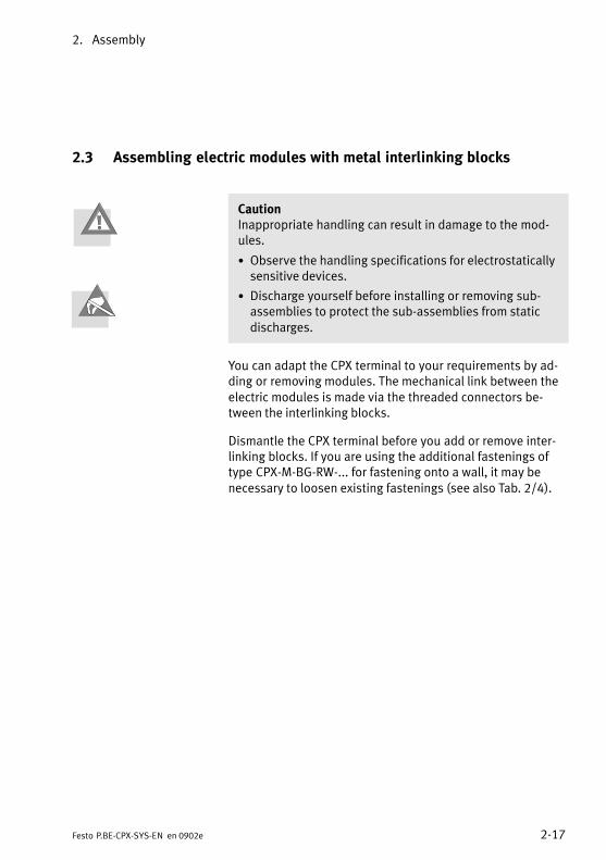
2.3 Assembling electric modules with metal interlinking blocks
CautionInappropriate handling can result in damage to the mod�ules.
· Observe the handling specifications for electrostaticallysensitive devices.
· Discharge yourself before installing or removing sub−assemblies to protect the sub−assemblies from staticdischarges.
You can adapt the CPX terminal to your requirements by ad�ding or removing modules. The mechanical link between theelectric modules is made via the threaded connectors be�tween the interlinking blocks.
Dismantle the CPX terminal before you add or remove inter�linking blocks. If you are using the additional fastenings oftype CPX−M−BG−RW−... for fastening onto a wall, it may benecessary to loosen existing fastenings (see also Tab.�2/4).

2. Assembly
2−18 Festo P.BE−CPX−SYS−EN en 0902e
2.3.1 Replacing a complete module or interlinking block
The interlinking blocks in the metal version are each linked tothe adjacent interlinking block or end plate by means ofscrews.
1 Connector screws 1
1 1
Fig.�2/9: CPX terminal with connection block and interlinking blocks in metal version
Dismantling Proceed as follows in order to remove a complete module ora�interlinking block:
1. Dismantle the CPX terminal
2. Unscrew and remove completely the two screws on theinterlinking block you wish to remove (see Fig.�2/9). Theinterlinking blocks are now held together only by the elec�trical plug connectors.
CautionMake sure that the electric plug connectors of the interlink�ing blocks are not bent.

2. Assembly
2−19Festo P.BE−CPX−SYS−EN en 0902e
3. Carefully pull apart the two halves of the CPX terminalwithout tilting them.
4. Repeat steps 1 to 3 on the left−hand side of the interlink�ing block you wish to remove.
Assembly To insert a module or interlinking block, proceed as follows:
1. Separate the CPX terminal at the place where you wish toinsert the new component by loosening the two connectorscrews (see Fig.�2/10), if you have not already done so.
CautionWhen interlinking blocks are arranged in series:Make sure that the electric plug connectors of the interlink�ing blocks are not bent.
2. Align the CPX terminal on a flat surface so that the compo�nents are not offset. The bolts attached to the left−handside of the interlinking block help you with the alignment.
3. Slide the interlinking blocks together carefully and with�out tilting.
4. Screw the connector screws a few turns into the adjacentinterlinking block.
5. Then tighten the screws equally with a size�SW4 internalhexagon socket with 3�Nm ±0.3�Nm.
6. Before fitting the connection blocks, make sure that theNBR seal is seated in the corresponding groove on theinterlinking block without twisting (see Fig.�2/10).
7. Assemble the CPX terminal (see section�2.4).

2. Assembly
2−20 Festo P.BE−CPX−SYS−EN en 0902e
1 Connector screws
2 Inserted NBRseal
1
1 1
2
Fig.�2/10: CPX terminal with connection block and interlinking blocks in metal version

2. Assembly
2−21Festo P.BE−CPX−SYS−EN en 0902e
2.4 Fitting the CPX terminal
NoteFit the CPX terminal so that there is sufficient space forheat dissipation and ensure that the maximum limits fortemperatures are observed (see Technical data).
You can fit the CPX terminal in one of two ways:
Mounting method Description
H−rail mounting The CPX terminal is suitable for fitting onto an H−rail (mounting rail asper EN�60715). There is a guide groove on the back for hanging thevalve terminal onto the H−rail.
Wall mounting The end plates and the pneumatic interface contain holes for fittingthe terminal onto a wall. CPX terminals with four or more interlinkingblocks require additional mounting components for the electric modules.
Tab.�2/2: Methods of fitting the CPX terminal
2.4.1 Fitting CPX terminals without pneumatics onto a H−rail
For fitting the CPX terminal without pneumatics onto an H−rail,you will require mounting kit type CPA−BG−NRH. This kit con�tains 2�clamping components and 2�M4x12 screws.
Fitting onto an H−rail is carried out in the same manner asfitting CPX terminals with pneumatics onto an H−rail (see sec�tion�2.4.2).
2. Assembly
2−22 Festo P.BE−CPX−SYS−EN en 0902e
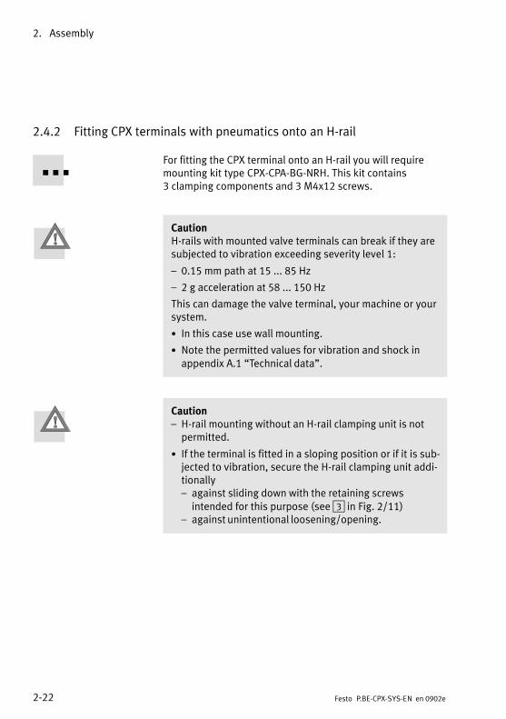
2.4.2 Fitting CPX terminals with pneumatics onto an H−rail
For fitting the CPX terminal onto an H−rail you will requiremounting kit type CPX−CPA−BG−NRH. This kit contains3�clamping components and 3�M4x12 screws.
CautionH−rails with mounted valve terminals can break if they aresubjected to vibration exceeding severity level 1:
� 0.15 mm path at 15 ... 85 Hz
� 2 g acceleration at 58 ... 150 Hz
This can damage the valve terminal, your machine or yoursystem.
· In this case use wall mounting.
· Note the permitted values for vibration and shock inappendix A.1 �Technical data".
Caution� H−rail mounting without an H−rail clamping unit is notpermitted.
· If the terminal is fitted in a sloping position or if it is sub�jected to vibration, secure the H−rail clamping unit addi�tionally� against sliding down with the retaining screws intended for this purpose (see 3 in Fig.�2/11)
� against unintentional loosening/opening.

2. Assembly
2−23Festo P.BE−CPX−SYS−EN en 0902e
Variant Mounting points
1
2
1
CPX terminal with MPA pneumaticsRequired mounting of the H−rail clamp�ing units:� In the end plates:
each with one M4 screw 1� In the pneumatic interface:
with an M4 screw 2
1 1
2 CPX terminal with VTSA pneumaticsRequired mounting of the H−rail clamp�ing units:� In the end plates:
each with one M4 screw 1� In the pneumatic interface:
with an M4 screw 2
ÒÒÒÒÒÒÒÒ
ÒÒÒÒ
1
2
1
CPX terminal with CPA pneumaticsRequired mounting of the H−rail clamp�ing units:� In the end plates:
each with one M4 screw 1� In the pneumatic interface:
with an M4 screw 2
Tab.�2/3: Required mounting points for H−rail mounting
For information about H−rail mounting of CPX terminals withMidi/Maxi pneumatics, see section �2.4.3.
2. Assembly
2−24 Festo P.BE−CPX−SYS−EN en 0902e
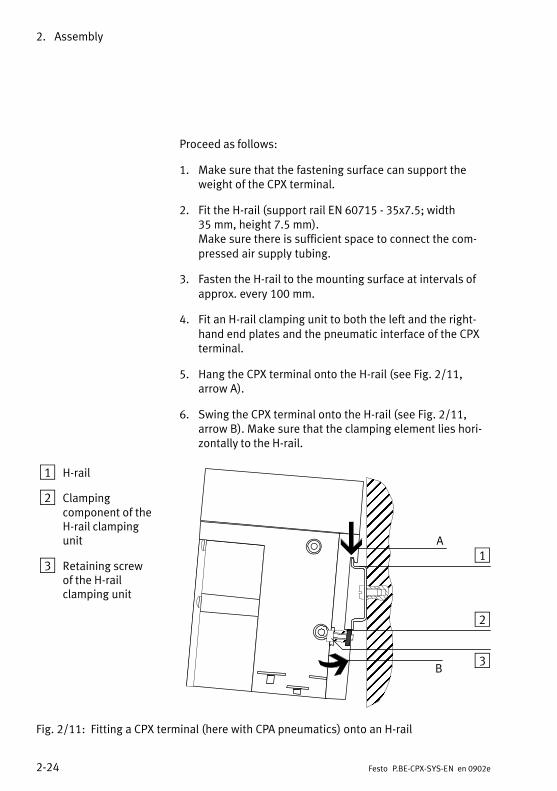
Proceed as follows:
1. Make sure that the fastening surface can support theweight of the CPX terminal.
2. Fit the H−rail (support rail EN 60715 − 35x7.5; width35�mm, height 7.5 mm).Make sure there is sufficient space to connect the com�pressed air supply tubing.
3. Fasten the H−rail to the mounting surface at intervals ofapprox. every 100 mm.
4. Fit an H−rail clamping unit to both the left and the right−hand end plates and the pneumatic interface of the CPXterminal.
5. Hang the CPX terminal onto the H−rail (see Fig.�2/11,arrow A).
6. Swing the CPX terminal onto the H−rail (see Fig.�2/11,arrow B). Make sure that the clamping element lies hori�zontally to the H−rail.
1 H−rail
2 Clampingcomponent of theH−rail clampingunit
3 Retaining screwof the H−railclamping unit
ÓÓÓÓÓÓÓÓÓÓÓÓÓÓÓÓÓÓÓÓÓÓÓÓÓÓÓÓÓÓÓÓÓÓÓÓ
ÔÔÔÔÔÔÔÔÔÔÔÔÔÔÔÔÔÔÔÔÔÔÔÔÔÔÔÔÔÔÔÔÔÔÔÔÔÔÔÔ
ÖÖÖÖÓÓÓÓ
1A
B
2
3
Fig.�2/11: Fitting a CPX terminal (here with CPA pneumatics) onto an H−rail

2. Assembly
2−25Festo P.BE−CPX−SYS−EN en 0902e
7. Fasten the CPX terminal against tilting or sliding bytightening the locking screws with 1.3�Nm.
1 H−rail
2 Clampingcomponent of theH−rail clampingunit
1
2
Fig.�2/12: Rear view: Fitting the CPX terminal onto an H−rail

2. Assembly
2−26 Festo P.BE−CPX−SYS−EN en 0902e
2.4.3 Fitting CPX terminals with Midi/Maxi pneumatics onto an H−rail
For fitting the valve terminal onto the H−rail you will require anH−rail clamping unit type CPX−03−4,0 (Midi) or typeCPX−03−7,0 (Maxi).
Caution� H−rail mounting without an H−rail clamping unit is notpermitted.
· If the terminal is fitted in a sloping position or if it is sub�jected to vibration, secure the H−rail clamping unit addi�tionally� against sliding down with the retaining screws intended for this purpose (see Fig.�2/13, item 6)
� against unintentional loosening/opening.
Note� If the terminal is fitted in a horizontal position and theload is at rest, it is not necessary to use the screws tosecure the H−rail clamping unit (see Fig.�2/13, item 6).
� If your CPX terminal does not have an H−rail clampingunit, you can order this and fit it at a later stage.
� The existing end plates (MIDI/MAXI) determine whetherMIDI or MAXI clamping elements are to be used.
Fasten the H−rail clamping unit to the rear of the right−handend plate and the pneumatic interface as described below.
Before fitting
· Glue the rubber feet on (�4 in Fig.�2/13). Make sure thatthe surfaces to be glued are clean (clean with spirit).
· Tighten the flat−head screws (see Fig.�2/13, item 3).
· Make sure that the spacer discs have been removed.

2. Assembly
2−27Festo P.BE−CPX−SYS−EN en 0902e
After fitting
· Secure the levers with the aid of the locking screws (seeFig.�2/13, item 6).
2
3
4
5
6
1
1 Lever*)
2 O−ring
3 Flat−head screw
4 Self−adhesive rubber foot
5 Clamping elements
6 Retaining screw
*) Different lever lengths with MIDI and MAXI
Fig.�2/13: Fitting the H−rail clamping unit

2. Assembly
2−28 Festo P.BE−CPX−SYS−EN en 0902e
Fit the H−rail as follows:
1. Make sure that the fastening surface can support theweight of the CPX terminal.
2. Fit an H−rail (support rail as per EN 60715 − 35x15; width 35 mm, height 15 mm).
3. Fasten the H−rail at least every 100 mm to the fasteningsurface.
4. Hang the CPX terminal onto the H−rail. Secure the CPXterminal on both sides with the H−rail clamping unitagainst tilting or sliding down (see Fig.�2/14).
5. With a vibrating load or if the node is fitted in a slopingposition, secure the H−rail clamping unit against uninten�tional loosening or opening with two locking screws(Fig.�2/14, item 4).
1
3
2
4
1 H−rail
2 H−rail clamping unit unlocked
3 H−rail clamping unit locked
4 Retaining screw
Fig.�2/14: Top view: Fitting the valve terminal onto an H−rail
2. Assembly
2−29Festo P.BE−CPX−SYS−EN en 0902e
2.4.4 Wall mounting
CautionWhen fitted onto a wall, the CPX terminal can bend and bedamaged in the following cases:
� When fitted to an uneven, flexible surface
� When CPX terminals with Midi/Maxi pneumatics arefitted without spacer discs (see Fig.�2/15)
� When fitted to a wall without additional fastening (seeTab.�2/4)
Fit the CPX terminal only onto a flat fixed surface. Makesure that the spacer discs are fitted before you mount theCPX terminal with Midi/Maxi pneumatics.
The end plates and the pneumatic interface contain holes forfitting the terminal onto a wall.
Spacer discs for Midi/Maxi pneumatics
To compensate for the differences in height between thepneumatic and electrical sides, you have to fit spacer discsfor a CPX terminal with Midi/Maxi pneumatics. Fit two spacerdiscs on each of the following:
� On the pneumatic interface for Midi/Maxi
� On the end plate
The spacer discs have one self−adhesive side to simplify theassembly process. Remove the protective foil before mount�ing.
Note Fig.�2/15 and the relevant fitting instructions.

2. Assembly
2−30 Festo P.BE−CPX−SYS−EN en 0902e
1 Spacer discs onthe Midi/Maxipneumaticinterface
2 Spacer discs onthe right−handend plate
1
2
Fig.�2/15: For wall mounting with Midi/Maxi pneumatics: remove the protective foil fromthe adhesive surface and fit the spacer disc (rear view)

2. Assembly
2−31Festo P.BE−CPX−SYS−EN en 0902e
Fitting the CPX terminal onto a wall
CautionOverloading the mounting holes, bending the CPX terminalor natural resonance can cause damage.
Every 100 or 150 mm, use additional mountings of the typeCPX−BG−RW−... for plastic version interlinking blocks, ortype CPX−M−BG−RW−... for metal version interlinking blocks.
Fastenings of type CPX−BG−RW−... can be clipped into two adjacent interlinking blocks (see Tab.�2/4) and provide addi�tional holes for fitting onto a wall. Note the relevant fittinginstructions.Fastenings of type CPX−M−BG−RW−... can be screwed ontometal version interlinking blocks with the enclosed screws(see Tab.�2/4) and provide additional holes for fitting onto a wall.

2. Assembly
2−32 Festo P.BE−CPX−SYS−EN en 0902e
Mounting Assembly
Type CPX−BG−RW−... for interlinking blocks in plastic design:1. Fit the fastenings 12. Clip the fastenings into
place 2
1
2
Type CPX−M−BG−RW−... for interlinking blocks in metaldesign:Fix the mounting bracket 1to the interlinking block withthe enclosed screws 2
12
Tab.�2/4: Fitting additional attachments for wall mounting
For fitting onto a wall, proceed as follows:
1. Make sure that the fastening surface is flat and can sup�port the weight of the CPX terminal.

2. Assembly
2−33Festo P.BE−CPX−SYS−EN en 0902e
2. For CPX terminals with 4 or more interlinking blocks: youwill require additional mounting brackets of typeCPX−(M−)BG−RW−... every 100 or�150 mm. These are ready−fitted on delivery.
3. For CPX terminals with MPA pneumatics:Check whether you need additional wall supports for thepneumatics module (see MPA pneumatics manual).For CPX terminals with Midi/Maxi pneumatics:Make sure that the spacer rings have been fitted (seeabove in this section).
4. Configure the CPX terminal as follows (see also Tab.�2/5and Tab.�2/6):
� Any mounting position
� Two screws at each of the end plates
� Screws on the additional mounting elements of type�CPX−(M−)BG−RW−...
� 2 or 3�screws on the pneumatic interface
Make sure there is sufficient space for connecting the powersupply cables and tubing and for heat dissipation.

2. Assembly
2−34 Festo P.BE−CPX−SYS−EN en 0902e
Variant Mounting points
X 1
X 2
X 3
X 4
X 1
X 2
X 3
X 4
X 1
X 2
X 3
X 4
1 2 1
2
CPX terminal in plastic version, withoutpneumaticsRequired mounting with:� End plates 1: two M4 or M6 screws
each� For each additional mounting
bracket�2� (needed if 4 or more interlinking blocks are used, seeTab.�2/4), type CPX−BG−RW−...: oneM4 screw
1 2 1 CPX terminal in metal version, withoutpneumaticsRequired mounting with:� End plates 1: two M4 or M6 screws
each� For each additional mounting
bracket�2� (needed if 4 or more interlinking blocks are used, seeTab.�2/4), type CPX−M−BG−RW−...: oneM6 screw
2
1 132 4 CPX terminal in plastic version withMPA pneumaticsRequired mounting with:� End plates 1: two M4 or M6 screws
each� For each additional mounting
bracket�2 (needed if 4 or more interlinking blocks are used, seeTab.�2/4), type CPX−BG−RW−...: oneM4 screw
� Pneumatic interface 3: two M4 screws
� For each mounting bracket 4 (seeMPA pneumatics manual) for MPApneumatics: one M6 screw
Tab.�2/5: Mounting points required for wall mounting (part 1)

2. Assembly
2−35Festo P.BE−CPX−SYS−EN en 0902e
Variant Mounting points
1 2
2
3 4 CPX terminal in plastic version with VTSApneumaticsRequired mounting with:� Left end plate 1�: two M4 or M6 screws� For each additional mounting bracket
(not shown, needed if 4 or more inter−linking blocks are used, see Tab.�2/4),type CPX−BG−RW−...: one M4 screw
� Pneumatic interface 2: two M6 screwswith internal hex
� Optional: Mounting bracket 3 (secondvariant not shown) for VTSA pneumaticson the pneumatic supply plate: one M5screw or one M5 and one M6 screw
� Right end plate 4: two M6 screws
1 2 3 CPX terminal in plastic version with Midi/Maxi pneumaticsRequired mounting with:� Left end plate 1: two M4 or M6 screws� For each additional mounting bracket
(not shown, needed if 4 or more inter−linking blocks are used, see Tab.�2/4),type CPX−BG−RW−...:one M4 screw
� Pneumatic interface 2: two M6 screws� Right end plate 3: two M6 screws
ÒÒÒ
ÒÒÒÒÒÒ
1 2
2
3 CPX terminal in plastic version with CPApneumaticsRequired mounting with:� Left end plate 1: two M4 or M6 screws
each� For each additional mounting bracket
(not shown, needed if 4 or more inter−linking blocks are used, see Tab.�2/4),type CPX−BG−RW−...: one M4 screw
� Pneumatic interface: two (optionally three) M4 screws 2
� Right end plate 3: two M4 screws
Tab.�2/6: Mounting points required for wall mounting (part 2)

2. Assembly
2−36 Festo P.BE−CPX−SYS−EN en 0902e

Installation
3−1Festo P.BE−CPX−SYS−EN en 0902e
Chapter 3

3. Installation
3−2 Festo P.BE−CPX−SYS−EN en 0902e
Contents
3. Installation 3−1 . . . . . . . . . . . . . . . . . . . . . . . . . . . . . . . . . . . . . . . . . . . . . . . . . . .
3.1 General installation instructions 3−3 . . . . . . . . . . . . . . . . . . . . . . . . . . . . . . . . . . .
3.1.1 Connecting cable 3−3 . . . . . . . . . . . . . . . . . . . . . . . . . . . . . . . . . . . . . . . .
3.1.2 Configuration of the CPX bus node 3−6 . . . . . . . . . . . . . . . . . . . . . . . . .
3.1.3 Configuration of the pneumatics 3−7 . . . . . . . . . . . . . . . . . . . . . . . . . . .
3.1.4 Selecting the power supply unit 3−8 . . . . . . . . . . . . . . . . . . . . . . . . . . . .
3.1.5 Power supply of the CPX terminal 3−12 . . . . . . . . . . . . . . . . . . . . . . . . . .

3. Installation
3−3Festo P.BE−CPX−SYS−EN en 0902e
3.1 General installation instructions
NoteObserve the following if the UL requirements are to becomplied with in your application:
� Rules for observing the UL certification can be found inthe separate UL−specific documentation. The relevanttechnical specifications listed there also apply here.
� The technical specifications in this documentation mayshow different values.
WarningUncontrolled movements of the connected actuators anduncontrolled movements of loose tubing can cause injuryto human beings or damage to property.
Before carrying out installation and maintenance work,switch off the following:
� Compressed air supply
� The operating and load voltage supplies.
3.1.1 Connecting cable
Field bus cable Use a suitable cable for your field bus system. Refer to themanual for your controller for the type of cable to be used.Also take into account here the distance and the fieldbusbaud rate.
Operating voltage cable Use a cable for the operating voltage with sufficient cross−sectional area. Avoid long distances between the power unitand the CPX terminal. Long operating voltage cables reduce thevoltage supplied by the power unit.
If necessary, ascertain the suitable cross−sectional area of thecable and the maximum permitted cable length in accordancewith the general rule in section A.2.

3. Installation
3−4 Festo P.BE−CPX−SYS−EN en 0902e
Pre−assembling the connecting cable
CautionThe position of the pins on the plug is different from thaton the socket.
� See the manual for the CPX bus node in question fora�description of the pin assignment of the fieldbus inter�face.
� See manual �CPX I/O modules" for the pin assignmentof the sensor and actuator connections of input and out�put modules.
� The operating voltage and load voltage connections arein the form of plugs. The pin assignment can be found inthe following sections.
Use plugs and sockets from the Festo supply programmewhich match the outer diameter of the cables used.

3. Installation
3−5Festo P.BE−CPX−SYS−EN en 0902e
Pre−assembling the plugsand cables
Connect the plugs and cables as follows (example):
1. Open the plugs/sockets as follows:
· Power supply socket:Insert the mains power socket into the operating volt�age connection of the CPX terminal. Unscrew thehousing of the socket.Then remove the connecting part of the socket, whichis inserted in the operating voltage connection.
· Fieldbus socket and sensor plug (only with PG...):Loosen the centre knurled nut.
1 Cable
2 Strain relief
3 Housing
4 Connecting part
12
3
4
Fig.�3/1: Individual parts of the socket and cable exit
2. Open the strain relief on the rear part of the housing.Then pass the cable through.
3. Remove 5 mm of insulation from the end of the conduc�tors and fit cable−end sleeves on the stranded wires.
4. Connect the ends of the conductors.

3. Installation
3−6 Festo P.BE−CPX−SYS−EN en 0902e
5. Replace the connecting part on the housing of the plug/socket. Pull the cable back so that there are no loops in�side the housing.
6. Tighten the strain relief.
3.1.2 Configuration of the CPX bus node
The characteristics of the CPX terminal can be adapted tovarious requirements.
Settings on the CPX busnode
CPX terminals can be coupled to various fieldbuses. Coupling is made via a CPX bus node that is adapted to suit the relevant fieldbus. The following settings can bemade, depending on the CPX node used:
� The fieldbus configuration (e.g. fieldbus address)
� Error characteristics of the CPX terminal
� Diagnostic behaviour of the CPX terminal
Depending on the CPX bus node used, important, application−specific settings can be made, if applicable, with DIL switcheson the CPX bus node. The DIL switches are behind an easilyaccessible cover on the CPX bus node.
Information about the installation and the setting options foryour CPX bus node can be found in the manual for the CPXbus node.

3. Installation
3−7Festo P.BE−CPX−SYS−EN en 0902e
3.1.3 Configuration of the pneumatics
MPA pneumatics
From a technical point of view, the individual MPA pneumaticmodules on the CPX terminal each represent an electric mod�ule with digital outputs for controlling the valves fitted. In thecase of VMPA1−FB−...−8, 8�digital outputs will always be as�signed and in the case of VMPA2−FB−...−4, 4�digital outputswill always be assigned.
VTSA, Midi/Maxi or CPA pneumatics
From a technical point of view, the pneumatic interfaces onthe CPX terminal are electric modules with digital outputs.
NoteWhen the pneumatics have been converted or extended,the number of output addresses occupied by the pneuma�tics for 8, 16, 24 or 32 outputs must be set on a DIL switchon the pneumatic interface.
The DIL switch is situated under the transparent cover on thepneumatic interface.
Detailed information on the pneumatic interfaces and MPApneumatic modules can be found in the manual for the �CPXI/O modules" of type P. BE−CPX−EA−...
3. Installation
3−8 Festo P.BE−CPX−SYS−EN en 0902e
3.1.4 Selecting the power supply unit
Warning· Use only PELV circuits as per IEC/DIN EN 60204−1 for theelectric power supply (protective extra−low voltage,PELV).Also observe the general requirements for PELV circuitslaid down in IEC/DIN EN 60204−1.
· Use only power sources that guarantee reliable electri�cal isolation of the operating voltage as per IEC/DIN�EN�60204−1.
Protection against electric shock (protection against directand indirect contact) is guaranteed in accordance with IEC/DIN EN 60204−1 by using PELV circuits (electrical equip�ment of machines, general requirements).
The current consumption of a CPX terminal depends on thenumber and type of integrated modules and components.
Recommendation:
· Use regulated power supply units, to ensure that the loadvoltage of the outputs remains within the permitted toler�ances even during continuous operation.
· Select power supply units that provide sufficient outputreserves for later extensions to the CPX terminal.
NoteWhen selecting the power supply units, check that theyhave sufficient output. If necessary, ascertain the currentconsumption according to the following tables.

3. Installation
3−9Festo P.BE−CPX−SYS−EN en 0902e
Calculation The following tables show how to calculate the current con�sumption of the system supply and the additional supplies.Please refer to the relevant technical specifications for thecurrent consumption of the valves and modules.
System supply type CPX−(M−)GE−EV−S...Current consumption of the operating voltage supply for the electronics and sensors
CPX bus node current consumption (rounded) approx. 200mA
Maximum current consumption of the CPX modules sup�plied via the system supply (internal electronics) 1) + _____ A
Current consumption of the sensors supplied via the sys�tem supply �(see manufacturer’s specifications) + _____ A
Current consumption of the technology modules sup�plied2)
+ _____ A
Sum of the current consumption of the operating voltage = _____ A � ______ A
Current consumption of the load voltage supply for valves and outputs
Current consumption of all simultaneously activatedelectric outputs that are supplied via the system supply(internal consumption at logic 1) 3)
� _____ x _____A
Load current of simultaneously activated outputs sup�plied via the system supply
+ _____ A
Current consumption of all simultaneously energisedvalve coils�4)
+ _____ A
Current consumption of the technology modules sup�plied 2)
+ _____ A
Sum of the current consumption of the load voltage = _____ A + ______ A
Total current consumption of the system supply = ______ A
1) See technical specifications of the I/O modules, pneumatic modules and MPA modules2) Including further modules and components supplied via the technology module3) Internal consumption at logical 1 see technical specifications for the output module4) Current consumption depends on valve type (see technical specifications of the valves)
Tab.�3/1: Table for calculating the current consumption − system supply

3. Installation
3−10 Festo P.BE−CPX−SYS−EN en 0902e
CautionShort circuits can cause damage.
Provide external fuse protection for the system supply andthe additional supplies. The permissible current per pin atthe supplies is:
� 7/8" plug, 4−pin: max. 10�A 1) 2)
� 7/8" plug, 5−pin: max. 8�A 1)
� M18 plug (4−pin): max. 16�A 2)
� Push−pull plug (5−pin): max. 16�A1) Limited by the specification of the connected plug con�nector. Values apply for plug connectors from Festo Acces�sories. If using third−party products, comply with the appli�cable specifications.2) Please note that with a 4−pin system supply via pin�0�V", the sum of both currents of the operating and loadvoltages flows.
Additional supply (optional) for outputs type CPX−(M−)GE−EV−Z...Current consumption of load voltage supply outputs
Current consumption of all simultaneously activatedelectric outputs that are supplied via the additional sup�ply (internal consumption at logic 1) 1)
� _____ x _____A
Load current of simultaneously activated outputs sup�plied via the additional supply
+ _____ A
Current consumption of the technology modules sup�plied 2)
+ _____ A
Sum of the current consumption of the load voltage = _____ A + ______ A
Total current consumption of the additional supply = ______ A
1) For the internal consumption at logical 1, see technical data for the output module2) Including further modules and components supplied via the technology module
Tab.�3/2: Table for calculating the current consumption of the additional supply for theoutputs

3. Installation
3−11Festo P.BE−CPX−SYS−EN en 0902e
Additional supply (optional) for valves of type CPX−(M−)GE−EV−V...Current consumption of load voltage supply valves
Current consumption of all simultaneously energisedvalve coils�1)
� _____ A
Current consumption of the technology modules sup�plied 2)
+ _____ A
Sum of the current consumption of the load voltage = _____ A + ______ A
Total current consumption of the additional supply = ______ A
1) Current consumption depends on valve type (see technical data for the valves)2) Including further modules and components supplied via the technology module
Tab.�3/3: Table for calculating the current consumption of the additional supply for thevalves
Information about the power supply concept of the CPX ter�minal can be found in section 1.1.3.The pin allocation for all alternative connections is describedin Tab.�3/4 and in the package insert for the interlinkingblock, together with the supply.

3. Installation
3−12 Festo P.BE−CPX−SYS−EN en 0902e
3.1.5 Power supply of the CPX terminal
NoteCheck within the framework of your EMERGENCY STOPconcept to ascertain the measures necessary for puttingyour machine/system into a safe state in the event of anEMERGENCY STOP (e.g.�switching off the operating voltagefor the valves and output modules, switching off the com�pressed air).
NoteWhen supplying power to CPX terminals with connectedpneumatics:
· Note that the lower tolerance range of the pneumaticsmust be observed when the operating and load voltagesupplies are provided by a power unit.Tolerance ranges:− MPA pneumatics: ±25�%,− VTSA pneumatics: ±10�%− Midi/Maxi pneumatics:±10�%− CPA pneumatics: +10/−15�% or − CPX−CP interface: +10/−15�%.
Power is supplied to the CPX terminal (in the form of operat�ing and load voltages) via supplies in the interlinking blocks(see section�1.1.3 for an overview of the supplies). These con�duct the operating and load voltages to the neighbouringmodules.
3. Installation
3−13Festo P.BE−CPX−SYS−EN en 0902e
Supplying operating and load voltage
Interlinking blocks withsystem supplyTypes CPX−(M−)GE−EV−S...
The operating and load voltages for the CPX terminal aresupplied via these interlinking blocks. The voltages are sup�plied via an M18, 7/8" or push−pull plug and can be used forfurther electric modules and for the valves on either side.
If interlinking blocks with additional supply are not required,the interlinking block with the system supply can be fitted inany desired position.
If interlinking blocks with additional supply are required,these must always be placed to the right of the system supply(see also Fig.�3/2).
Interlinking blocks withadditional supply for elec�tric outputsTypes CPX−(M−)GE−EV−Z...
The additional load voltage for the electric outputs is sup�plied via these interlinking blocks. The load voltage for theoutput modules is also supplied via an M18, 7/8" or push−pull plug and can be switched off separately. These interlinking blocks must always be placed to the rightof a system supply and, in the case of a push−pull connec�tion, must not be combined with a forwarding functionwithin a CPX terminal.
The use of interlinking blocks with additional supply for elec�tric outputs causes the following (see also Fig.�3/2):
� The load voltage for electric output modules will beinterrupted to the previous module on the left.
� The load voltage supplied will be available to the inte�grated module and, where applicable, to the followingmodules on the right.
� The operating and load voltage supplies for the valveswill be transmitted further.
� Several additional supplies for electric outputs in aCPX terminal are possible.

3. Installation
3−14 Festo P.BE−CPX−SYS−EN en 0902e
Interlinking block withadditional power supplyfor valves Types CPX−GE−EV−V...
These interlinking blocks enable separate circuits to becreated for supplying load voltage to the valves. The loadvoltage for the valves, which is also supplied via an M18 or7/8" plug, can be switched off separately. This interlinkingblock must also always be placed to the right of a systemsupply.
The use of interlinking blocks with additional supply forvalves causes the following (see also Fig.�3/2):
� The load voltage for the valves will be interrupted at theprevious module on the left.
� The load voltage supplied is available for the followingmodules:
� Subsequent pneumatic modules/valves to the right
� CP modules that are connected to the fitted CPX−CPinterface and to those CPX−CP interfaces subsequentlyfitted to the right
� The operating and load voltage supplies for the electricoutputs will be transmitted further.
� These additional supplies must not be used for MPApneumatics with MPA electronic modules of the typeVMPA...−FB−EMS−... (see description of P.BE−MPA−ELEK�TRONIK−...).
Interlinking blocks withpush−pull forwardingfunction of type CPX−M−GE−EV−S−PP−5POL
These interlinking blocks are used to forward the powersupply to subsequent external equipment. These interlinking blocks must be placed directly to the rightof a system supply and must not be used more than oncewithin a CPX terminal. They must not be combined with anadditional supply, either.

3. Installation
3−15Festo P.BE−CPX−SYS−EN en 0902e
CautionDamage to device and the environment
CPX terminals with push−pull forwarding function musthave external fuse protection to 16�A in order to avoidoverloading and resultant damage to the device and itsenvironment.
The use of interlinking blocks with forwarding function forsupplying power to subsequent equipment causes the follow�ing (see also Fig.�3/2):
� The operating voltage supply and the load voltagesupply are forwarded/connected through to subse�quent equipment via the push−pull connection. Thisreplaces a T−adapter in the field.
� The operating voltage supply and the load voltagesupply are available to the fitted output module andsubsequent output modules to the right.
� Interlinking blocks with a push−pull forwarding func�tion are identically constructed to those with a�push−pull system power supply
Interlinking blocks withoutsupplyTypes CPX−(M−)GE−EV
These interlinking blocks serve for the electrical linking ofmodules which do not require a separate load voltage supply.

3. Installation
3−16 Festo P.BE−CPX−SYS−EN en 0902e
Internal voltage forwarding
The operating voltage supplied (internal electronics/inputs)and load voltage (valves/outputs) are forwarded in the inter�linking blocks via what are known as contact rails. Fig.�3/2and Fig.�3/3 show the differences between 4−pin and 5−pinalternative connections:
1
2
3
4
CPX−GE−EV−S CPX−GE−EV CPX−GE−EV−Z CPX−GE−EV−V
5
0 Vval24 Vval
0 VOUT24 VOUT
0 Vel/sen24 Vel/sen
FE
0 Vval24 Vval
0 VOUT
24 VOUT
6
1 Load voltage for valves (24 Vval and 0 Vval)
2 Load voltage for digital outputs (24 Vout and 0 Vout)
3 Operating voltage for electronics andsensors (24 Vel/sen and 0 Vel/sen)
4 Functional earth (FE)
5 Rails for internal functions
6 Connection to FE connection on endplate
Fig.�3/2: Basic representation of the power supply concept for interlinking blocks with4−pin alternative connections (M18, 7/8")

3. Installation
3−17Festo P.BE−CPX−SYS−EN en 0902e
Separate circuits Interlinking blocks with a 5−pin plug enable separate circuitsto be created for supplying load voltage to the outputs/valves and for supplying operating voltage to the electronics/sensors. Fig.�3/3 provides an overview.
1
2
3
4
CPX−(M−)GE−EV−S−... CPX−(M−)GE−EV CPX−(M−)GE−EV−Z−...
5
0 Vval24 Vval
0 VOUT24 VOUT
0 Vel/sen24 Vel/sen
FE
0 VOUT
6
24 VOUT
1 Load voltage for valves (24�Vval and0�Vval)
2 Load voltage for digital outputs(24�Vout and 0�Vout)
3 Operating voltage for electronics andsensors (24�Vel/sen and 0�Vel/sen)
4 Functional earth (FE)
5 Rails for internal functions
6 Connection to FE connection on end plate
Fig.�3/3: Basic representation of the power supply concept for interlinking blocks with5−pin alternative connections (7/8", push−pull)
The pin allocation for all alternative connections is describedin Tab.�3/4 and in the package insert for the interlinkingblocks with supply.

3. Installation
3−18 Festo P.BE−CPX−SYS−EN en 0902e
Special features concerning the use of the CPX−CP interface
NoteThe CPX−CP interface connects the current rails 0�Vel/senand 0�Vval of the CPX valve terminal. This means that theseparate circuits for the operating voltage for the electro�nics/sensors (Vel/sen) and the load supply for the valves(Vval) will no longer be effective until the next additionalsupply for valves following the CPX−CP interface.
Further information on the power supply for the CPX terminalin conjunction with the CPX−CP interface can be found in themanual for the CPX−CP interface in the section �Installation" �section �Power supply concept − forming voltage zones."
Pin allocation for the alternative connections
CautionShort circuits can cause damage.
Provide external fuse protection for the system supply andadditional supplies. The permissible current per pin at thesupply is:
� 7/8" plug, 4−pin: max. 10�A 1) 2)
� 7/8" plug, 5−pin: max. 8�A 1)
� M18 plug (4−pin): max. 16�A 2)
� Push−pull plug (5−pin): max. 16�A1) Limited by the specification of the connected plug con�nector. Values apply for plug connectors from Festo Acces�sories. If using third−party products, comply with the appli�cable specifications.2) Please note that with a 4−pin system supply via pin�0�V", the sum of both currents of the operating and loadvoltages flows.

3. Installation
3−19Festo P.BE−CPX−SYS−EN en 0902e
Plugs(t i
Interlinking block with(top view of device)
System supplyType CPX−(M−)GE−EV−S...
Additional power supplyType CPX−(M−)GE−EV−Z...
Valve supplyType CPX−GE−EV−V...
7/8"−4POL 1)
DC
B A
A: 24�Vel/senB: 24�Vval / 24�VoutC: FED:0�Vel/sen /
0�Vval / 0�Vout
A: not connectedB: 24�VoutC: FED:0�Vout
A: not connectedB: 24�VvalC: FED:0�Vval
7/8"−5POL
1234 5
1: 0�Vval / 0�Vout2: 0�Vel/sen3: FE4: 24�Vel/sen5: 24�Vval / 24�Vout
1: 0�Vout2: not connected3: FE4: not connected5: 24�Vout
�
M18
1 234
1: 24�Vel/sen2: 24�Vval / 24�Vout3: 0�Vel/sen /
0�Vval / 0�Vout4: FE
1: not connected2: 24�Vout3: 0�Vout4: FE
1: not connected2: 24�Vval3: 0�Vval4: FE
Push−pull 2) 1: 24�Vel/sen2: 0�Vel/sen3: 24�Vval / 24�Vout4: 0�Vval / 0�Vout5: FE
1: not connected2: not connected3: 24�Vout4: 0�Vout5: FE
�
Vel/sen: Operating voltage for electronics/sensorsVout: Load voltage for outputsVval: Load voltage for valvesFE: Functional earth
1) Note the specifications on the plug.2) Interlinking blocks with forwarding function and interlinking blocks with system supply are
identically constructed.
Tab.�3/4: Pin assignment for interlinking blocks with system supply, additional supply orvalve supply

3. Installation
3−20 Festo P.BE−CPX−SYS−EN en 0902e
Potential equalisation
The CPX terminal has two earthing connections for potentialequalisation:
� The �functional earth" pin from system supply, additionalsupply or valve supply (see Tab.�3/4)
� Earth connection on the left−hand end plate (see Fig.�3/4).
Note· Always connect the �functional earth" to the earth po�tential.
· Connect the earth connection of the left−hand end plateto the earth potential with low impedance (short cablewith large cross−sectional area).
· With low−impedance connections you can ensure thatthe earth connection at the left−hand end plate and theearth connection at the supplies have the same potentialand that there are no equalising currents.
You can thereby avoid interference from electromagneticsources and ensure electromagnetic compatibility in accor�dance with EMC directives.
Connection examples
Connection example 1 Fig.�3/4 shows as an example the connection of a common24�V supply for pin�1 and pin�2 on the M18 plug. Please notethat:
� The tolerance of 24�V�DC ±25�% must be observed.
� Both connections for potential equalisation are connectedand that compensating currents must be prevented
� The load voltage at pin�2 of the M18 plug (valves and out�puts) can be switched off separately
� External fuses are used, depending on the application(maximum value at pin �0�V" in total for both fuses: 16�A)

3. Installation
3−21Festo P.BE−CPX−SYS−EN en 0902e
1 3 42 51
1 Potential equalisation of functionalearth (FE)
2 External fuses
3 Separately disconnectable load supplyfor valves and outputs
4 Earth terminal on pin�4, rated formax.�16�A
5 Connection for system supply, typeCPX−GE−EV−S
Fig.�3/4: Example � connecting a common 24�V power supply and the potential equalisa�tion (system supply with M18 plug)

3. Installation
3−22 Festo P.BE−CPX−SYS−EN en 0902e
Connection example 2 Fig.�3/5 shows an example connection with system supplyand an additional supply each for electric outputs and valves.
1
11
2 3 4
1
1 Potential equalisation of functional earth (FE)
2 Interlinking block with system supply, type CPX−GE−EV−S
3 Interlinking block with additional supply for outputs, type CPX−GE−EV−Z
4 Interlinking block with additional supply for outputs, type CPX−GE−EV−V
Fig.�3/5: Example − additional load supplies with a shared 24 V power supply (all sup�plies with M18 plugs)
Connection example 3 Fig.�3/6 shows an example connection with separate circuitsfor power supply. Interlinking blocks with 5−pin 7/8" or push−pull plugs are used to do this.

3. Installation
3−23Festo P.BE−CPX−SYS−EN en 0902e
1 2 3 4 5 6
1 Potential equalisation of functionalearth (FE)
2 Interlinking block with system supply,type CPX−GE−EV−S−7/8−5POL
3 Interlinking block with additionalsupply for outputs, type CPX−GE−EV−Z−7/8−5POL
4 MPA pneumatic module, supplied bythe system supply 2
5 Electrical supply plate with additionalpower supply for valves, type�VMPA−FB−SP−7/8−V−5POL
6 MPA pneumatic module, supplied bythe additional supply 5
Fig.�3/6: Example − power supply with separate circuits, separate power supply unit andinterlinking blocks with 5−pin 7/8" plugs (basic circuit diagram)

3. Installation
3−24 Festo P.BE−CPX−SYS−EN en 0902e

Commissioning
4−1Festo P.BE−CPX−SYS−EN en 0902e
Chapter 4

4. Commissioning
4−2 Festo P.BE−CPX−SYS−EN en 0902e
Contents
4. Commissioning 4−1 . . . . . . . . . . . . . . . . . . . . . . . . . . . . . . . . . . . . . . . . . . . . . . . .
4.1 Procedure for commissioning 4−3 . . . . . . . . . . . . . . . . . . . . . . . . . . . . . . . . . . . . .
4.2 Preparing the CPX terminal for commissioning 4−4 . . . . . . . . . . . . . . . . . . . . . . .
4.2.1 Parameter types 4−6 . . . . . . . . . . . . . . . . . . . . . . . . . . . . . . . . . . . . . . . .
4.2.2 Possibilities of parametrisation 4−9 . . . . . . . . . . . . . . . . . . . . . . . . . . . .
4.3 Start−up behaviour of the CPX terminal 4−10 . . . . . . . . . . . . . . . . . . . . . . . . . . . . .

4. Commissioning
4−3Festo P.BE−CPX−SYS−EN en 0902e
4.1 Procedure for commissioning
In order to avoid connecting errors and addressing errors,you should carry out commissioning in steps as follows. The individual commissioning steps are shown in Fig.�4/1.
1
23
1 Step 1 � Checking the valve/cylinder combinations (see manual for the specificpneumatics)
2 Step 2 � Checking the I/O assignment
3 Step 3 � Commissioning the CPX terminal on the fieldbus and checking theaddress assignment, if necessary, without connected actuators by means ofLED (see manual for the specific CPX bus node)
Fig.�4/1: Commissioning steps

4. Commissioning
4−4 Festo P.BE−CPX−SYS−EN en 0902e
4.2 Preparing the CPX terminal for commissioning
CPX terminals can be connected to various fieldbuses. Connection is made via the CPX bus node that is adapted tosuit the relevant fieldbus.
The reaction of the CPX terminal can be adapted to variousrequirements. You can carry out important settings as follows:
� With the DIL switch directly on the CPX bus node (seesection 3.1.2).
� By parametrisation (see section 4.2.1).
The DIL switch and the parameters are preset at the factory.
CautionIncorrectly set DIL switches and parameters can causedamage during operation. You must observe the followinginstructions in order to prevent damage.
· Check the DIL switch settings before using and replacingCPX terminals.
· Make sure that the desired parametrisation of the CPXterminal in the start−up phase or after fieldbus interrup�tions is carried out by the plug−in module or the scanner/bus master, providing this is supported by the fieldbusprotocol used. This is to ensure that if the CPX terminal isreplaced, the new terminal will also be operated with thedesired parameter settings.
Preparations Before commissioning a fieldbus system with CPX terminals,you should first prepare each individual CPX terminal forcommissioning.

4. Commissioning
4−5Festo P.BE−CPX−SYS−EN en 0902e
NoteDo not connect the cables for the fieldbus when preparingfor commissioning.
In this way, you can avoid:
� Addressing errors that may occur due to the modificationof the address range during operation with variousfieldbus systems.
Proceed with preparation as follows:
1. Check the pneumatic tubing of the valve terminals withthe aid of the manual override (see manual for specificpneumatics).
2. Check the entire electric wiring of the CPX terminal.
3. Check the DIL switch settings of your CPX terminals (see manual for the specific CPX bus node).

4. Commissioning
4−6 Festo P.BE−CPX−SYS−EN en 0902e
4.2.1 Parameter types
The parameters are preset at the factory. These pre−settingscan be used for a large number of applications. With the aidof parametrising, the characteristics of the CPX terminal orthe characteristics of the individual modules and I/O chan�nels can be adapted to each particular application.
The possibilities available depend on the fieldbus protocolused. Information about this can be found in the manual foryour CPX bus node.
A distinction is made between the following types of para�meters:
Types of parameters
Description
System parameters Influence the behaviour of the complete CPX terminal
Module parameters� module−specific
Influence the behaviour of a particular module
� channel−specific Influence the behaviour of a particular inputor output channel
Diagnostic memoryparameters
Influence the working method of the internaldiagnostic memory
Tab.�4/1: Types of parameters
The individual parameters are described in detail in AppendixB.2. Basic principles of using the parameters can be found inAppendix C. The tables below give a brief overview of themost important parameters.

4. Commissioning
4−7Festo P.BE−CPX−SYS−EN en 0902e
System parameters Brief description
Diagnostic monitoring with:� Short circuit/overload� Undervoltage of outputs� Undervoltage of valve supply
The monitoring of short circuit and overload for the complete CPXterminal can be switched on or off with this parameter.
Signal status when there isa�fault(Fail−safe parameter)
Defines the status which digital output signals (outputs andvalves) are to assume in the event of field bus communicationfaults.
Signal status in Idle mode Defines the status which digital output signals (outputs andvalves) are to assume when changing into the Idle status. Thisfunction is only relevant with certain fieldbus protocols (see manual for specific CPX bus node).
Force signal status(force parameter)
Enables the manipulation of signal states separate from actualoperating conditions and independent of the higher−order PLC/IPC.
System start Determines the start−up behaviour of the CPX terminal
Tab.�4/2: System parameters
Module−specific parame�ters
Brief description
Diagnostic monitoring with:� Short circuit/overload� Undervoltage� Wire break
The monitoring of short circuit/overload and undervoltage on themodule can be switched on or off with this parameter.
Reaction after:� Short circuit/overload� Wire break
Determines after a short circuit/overload or wire fracture whetherthe power is to remain switched off or whether it is to be switchedon again automatically.
Input debounce time Serves for trouble−free recognition of digital input signals
Signal stretching time Serves for recognising short signals
Data format of analogue values See manual for the relevant analogue module
Tab.�4/3: Module parameters � part 1

4. Commissioning
4−8 Festo P.BE−CPX−SYS−EN en 0902e
Channel−specific parameters Brief description
Signal extension Serves for recognising short signals
Monitoring of wire break Serves for recognising connection faults
Fault mode Defines the status that the relevant channel is to assume inthe event of fieldbus communication faults
Fault statethe event of fieldbus communication faults.
Idle mode Defines the status which digital output signals (outputs andvalves) are to assume when the Idle function is accessed. This
Idle state
valves) are to assume when the Idle function is accessed. Thisfunction is only relevant with certain fieldbus protocols (seemanual for specific CPX bus node).
Force mode Actual signals are replaced in the processing image by the forcesettings
Force statesettings.
Tab.�4/4: Module parameters � part 2
Detailed information on the parameters, which are supportedby the module you are using used, can be found in the man�ual for the relevant module. Basic principles of using theparameters can be found in Appendix C.
Diagnostic memory parame�ters
Brief description
Entries, remanent Determines whether the contents of the diagnostic memory areto be retained after new Power on or whether they are to be de�leted.
Diagnostic memory filters
� Run/stop filter 1 + 2� Fault end filter� Fault number filter� Module/channel filter
With the diagnostic memory filters you can suppress the regis�tering of certain error messages and control both the startingand stopping of the fault registering.
Tab.�4/5: Diagnostic memory parameters

4. Commissioning
4−9Festo P.BE−CPX−SYS−EN en 0902e
4.2.2 Possibilities of parametrisation
The parametrisation of the CPX terminal can be undertakenas follows depending on the fieldbus protocol used:
ÔÔÔÔ
ÔÔÔÔÔÔÔÔ
ÖÖÖÖÖÒÒÒ
ÒÒÒ
ÒÒÒÒÒÒ
ÒÒÒ
ÒÒÒ
ÒÒÒÒÒÒ
ÒÒÒ
ÒÒÒ
ÒÒÒÒÒÒ
ÒÒÒ
ÒÒÒ
ÒÒÒ
ÒÒÒÒÒÒ
ÒÒÒ
1 2 3 4
1 Plug−in module or scanner/bus master; the desiredparametrisation can be guaranteed e.g. in the start−upphase or after fieldbus interruptions
2 User program in the higher−order PLC/IPC; parameterscan be modified during running time
3 Fieldbus−specific configurators; parameters can bemodified during the commissioning phase or during thesearch for errors
4 Handheld; parameters can be modified during thecommissioning phase, during the search for errors orduring running time
Fig.�4/2: Possibilities of parametrisation

4. Commissioning
4−10 Festo P.BE−CPX−SYS−EN en 0902e
4.3 Start−up behaviour of the CPX terminal
The desired parametrisation of the CPX terminal should becarried out in the start−up phase or after fieldbus interrup�tions by the plug−in module or the scanner/bus master, pro�viding this is supported by the fieldbus protocol used. In thisway you can be sure that when a CPX terminal has been re�placed, the new terminal is operated with the same para�meter settings.
You can influence the start−up behaviour with the aid of thesystem parameter System start (see section B.2.2). If possibleselect the setting �System start with default parameterisingand current CPX system equipment". The desired parameter�ising can then be created in the start−up phase or after field�bus interruptions e.g. by the plug−in module or the scanner/bus master (depending on the fieldbus used).
If the M�LED lights up permanently after the system start,then �System start with saved parametrising and saved CPXsystem equipment" is set.
CautionIn the case of CPX terminals on which the M−LED lights uppermanently, parametrising will not be restored automati�cally by the higher−order system if the CPX terminal is re�placed after servicing. In these cases check before repla�cing to see which settings are required and carry out thesesettings.
Detailed instructions can be found in the manual for the spe�cific CPX bus node or the manual for the handheld.

Diagnostics and error handling
5−1Festo P.BE−CPX−SYS−EN en 0902e
Chapter 5

5. Diagnostics and error handling
5−2 Festo P.BE−CPX−SYS−EN en 0902e
Contents
5. Diagnostics and error handling 5−1 . . . . . . . . . . . . . . . . . . . . . . . . . . . . . . . . . . .
5.1 General notes on diagnosis 5−3 . . . . . . . . . . . . . . . . . . . . . . . . . . . . . . . . . . . . . . .
5.1.1 On the spot diagnosis with LEDs 5−5 . . . . . . . . . . . . . . . . . . . . . . . . . . .
5.1.2 CPX−specific LEDs 5−6 . . . . . . . . . . . . . . . . . . . . . . . . . . . . . . . . . . . . . . .
5.2 Diagnosis via status bits or the I/O diagnostic interface 5−11 . . . . . . . . . . . . . . . .
5.2.1 Structure of the status bits 5−12 . . . . . . . . . . . . . . . . . . . . . . . . . . . . . . . .
5.2.2 The I/O diagnostic interface 5−14 . . . . . . . . . . . . . . . . . . . . . . . . . . . . . . .
5.2.3 Error numbers 5−19 . . . . . . . . . . . . . . . . . . . . . . . . . . . . . . . . . . . . . . . . . .

5. Diagnostics and error handling
5−3Festo P.BE−CPX−SYS−EN en 0902e
5.1 General notes on diagnosis
The CPX terminal offers extensive possibilities of diagnosisand error treatment. The following possibilities are available(see also Tab.�5/1):
X�1
X�2
X�3
X�4
X�1
X�2
X�3
X�4
X�1
X�2
X�3
X�4
1
2
3
1 On the spot diagnosis with LED
2 On the spot diagnosis with handheld
3 Diagnosis via the fieldbus
Fig.�5/1: Diagnostics options of the CPX terminal

5. Diagnostics and error handling
5−4 Festo P.BE−CPX−SYS−EN en 0902e
Diagnostics options Brief description see
1 On the spot diagnosis withLED
The LEDs on the electric and pneumatic modulesshow hardware faults, bus faults, etc.
Section 5.1.2
2 On the spot diagnosis withthe handheld
The handheld:� Shows current error messages in plain text� Offers access to the diagnostic memory
Manual forhandheld(CPX−MMI)
3 System status scanningwith the fieldbus (statusbits scanning)
The 8 status bits display common diagnosticmessages (global error messages).
Section 5.2.1
System diagnosis with thefieldbus (via I/O diagnosticinterface)
Internal diagnostic data can be read via the I/Odiagnostic interface. In this way detailed diagno�stic information can be accessed, even if thefieldbus used does not offer any extensive field�bus−specific diagnostic functions.The I/O diagnostic interface offers:� Access to the current error message� Access to the diagnostic memory� Read access to internal parameters and data.
Section 5.2.2
Fieldbus−specific diagno�stic functions
Special diagnostic functions or communicationservices are available, depending on the fieldbusused. For example communication services on:� DPV1 (PROFIBUS)� The PCP channel (Interbus)� SDO access (CANopen)
Manual for thespecific CPXbus node
Tab.�5/1: Diagnostics options of the CPX terminal

5. Diagnostics and error handling
5−5Festo P.BE−CPX−SYS−EN en 0902e
5.1.1 On the spot diagnosis with LEDs
The LEDs of the electric modules are situated under the trans�parent cover on the upper part of the module. The right−handrow of LEDs is identical on the different types of modules(standardised).
LEDs of the CPX bus node
CPX bus nodes have fieldbus−specific LEDs and CPX−specificLEDs. The CPX−specific LEDs are available on each CPX field�bus node:
1 Fieldbus−specificLEDs (see manual forthe specific CPX busnode)
2 CPX−specific LEDs(can be found onevery CPX bus node;see section 5.1.2)
PS
PL
SF
M
1 2
Fig.�5/2: LED display on the CPX bus node (example)

5. Diagnostics and error handling
5−6 Festo P.BE−CPX−SYS−EN en 0902e
5.1.2 CPX−specific LEDs
PS (power system) � power sensor/logic supply
LED (green) Sequence Status Meaning / error handling
LED lights up
ON
OFF
No error. Operating vol�tage/sensor supply applied
�
LED flashes
ON
OFF
Operating voltage/sensorsupply outside the tole�rance range
Eliminate undervoltage
LED flashesON
OFFInternal fuse for the opera�ting voltage/sensor supplyhas responded.
1. Eliminate short circuit/overload onmodule side.
2. Depends on the parametrisation ofthe module (module parameter):· The sensor supply voltage will be
switched on again automaticallyafter the short circuit has beeneliminated (default)
· Power Off/On is necessary
LED is off
ON
OFF
The operating voltage/sen�sor supply is not applied
Check the operating voltage connec�tion of the electronics
PL (Power Load) � power load supply (outputs/valves)
LED (green) Sequence Status Meaning / error handling
LED lights up
ON
OFF
No error. Load voltage ap�plied
No
LED flashes
ON
OFFLoad voltage at the systemsupply or additional supplyoutside the tolerancerange
Eliminate undervoltage

5. Diagnostics and error handling
5−7Festo P.BE−CPX−SYS−EN en 0902e
SF (system failure) � system fault
LED (red) Sequence 1) Status Meaning / error handling
LED is off
ON
OFFNo fault �
LED flashes
ON
OFFSimple fault/information(error class 1)
See explanation of fault numbers insection 5.2.3
LED flashes
ON
OFF
Error(error class 2)
See explanation of fault numbers insection 5.2.3
LED flashes
ON
OFF
Serious fault(error class 3)
See explanation of fault numbers insection 5.2.3
1) The system fault LED flashes depending on the class of fault which has occurred.Error class 1 (minor error): one flash, pauseError class 2 (error): flash twice, pauseError class 3 (serious error): flash three times, pause

5. Diagnostics and error handling
5−8 Festo P.BE−CPX−SYS−EN en 0902e
M (modify) � parametrising modified or forcing active
LED (yellow) Sequence Status Meaning / error handling
LED is off
ON
OFF
� System Start with de�fault parametrising (fac�tory setting) and currentCPX equipment status isset; external parametri�sing is possible (pre−set�ting) 1)
No
LED flashes
ON
OFFForce is active 2) The Force function is enabled (see sy�
stem parameter Force mode; functionno. 4402).
LED lights up
ON
OFF
� System start with savedparametrising and savedCPX equipment status isset; parameters and CPXequipment status aresaved remanently; exter�nal parametrising isblocked 1) 2)
Be careful when replacing CPX valveterminals with saved parametrising.With these CPX valve terminals, para�metrising is not carried out automati�cally by the higher−order PLC/IPCwhen the terminal is replaced. Inthese cases check before replacing tosee which settings are required and, ifnecessary, carry out these settings.
1) With CPX−FEC in the operating modes Stand Alone and Remote Controller (control function active)without meaning.
2) The display of the Force function (LED flashes) has precedence over the display of the setting forSystem start (LED lights up).

5. Diagnostics and error handling
5−9Festo P.BE−CPX−SYS−EN en 0902e
LEDS on CPX I/O modules
In addition to the module−specific LEDs, all electric moduleshave a module common error LED for module diagnosis.
1 Module commonerror LED (red)
2 Status LEDs (e.g.green for digital in�puts, yellow for digi�tal outputs)
3 Channel error LED(e.g. with digital out�puts)
0
1
2
3
8DI
4
5
6
7
1 1
2
0
1
2
3
4DO
32
Fig.�5/3: LED display of electric modules (example)
Status LEDs
There is a status LED for each channel. This LED indicates thestatus of the signal. This means:
Status LED(green or yellow)
Sequence Status
LED lights up 1)
ON
OFFChannel logical 1(signal present)
LED is off
ON
OFFChannel logical 0(no signal)
1) Lights up green for inputs and yellow for outputs

5. Diagnostics and error handling
5−10 Festo P.BE−CPX−SYS−EN en 0902e
Module common error LED
The red module common error LED indicates a module fault(e.�g. short circuit or overload).
The display of faults can be suppressed by module para�meters.
Module common error LED
LED (red) Sequence Status Error handling
LED is off
ON
OFF
Trouble−free operation No
LED flashes
Error−specific
See manual for the rel�evant module
See manual for the relevant module
LED lights up
ON
OFFModule common error (seemanual for the specificmodule)
e.g. Eliminate short circuit/undervol�tage
Channel error LED
Information about this can be found in the manual for therelevant CPX module.

5. Diagnostics and error handling
5−11Festo P.BE−CPX−SYS−EN en 0902e
5.2 Diagnosis via status bits or the I/O diagnostic interface
The CPX terminal offers the following two modes for diag�nosis, irrespective of the CPX bus node used:
Mode Description
Status bits(system status)
The status bits serve for displaying com�mon diagnostic messages (global faultmessage). Access to the status bits ismade via 8 internal inputs (see section5.2.1).
I/O diagnostic inter�face (system diagno�sis)
The I/O diagnostic interface is a fieldbus−independent diagnostic interface.With this interface, all internal data andparameters can be read out via 16 internalinputs and 16 internal outputs (see sec�tion 5.2.2 and Appendix B). All diagnosticinformation is then also available even ifthe fieldbus protocol used does not offerany extensive diagnostic functions.
Tab.�5/2: Fieldbus−independent diagnostic modes

5. Diagnostics and error handling
5−12 Festo P.BE−CPX−SYS−EN en 0902e
5.2.1 Structure of the status bits
Irrespective of the CPX bus node used, the CPX terminal pro�vides 8�status bits for displaying common diagnostic mess�ages (global error messages).
Status bits are configured like inputs. The input addresses,which are to be assigned to status bits, depend on the field�bus protocol used (see manual for the specific CPX busnode).
The status bits supply coded diagnostic information. Bits 0 to3 specify the module types in which faults have occurred. Bits4 to 7 specify the type of fault.
Bit Diagnostic informationwith 1−signal
Description
0 Error at valve Module type in which an error has occurred
1 Error at outputerror has occurred
2 Error at input
3 Error in analogue module/function module or techno�logy module
4 Undervoltage Type of error
5 Short circuit/overload
6 Wire break
7 Other error
Tab.�5/3: Structure of the status bits
If all status bits supply a 0−signal, no fault will be registered.

5. Diagnostics and error handling
5−13Festo P.BE−CPX−SYS−EN en 0902e
Examples of typical status information
No error registered
Other error
Wirebreak
Shortcircuit
Under�voltage
Funct./analo�gue
Input Output Valve
Bit 7 6 5 4 3 2 1 0
Status 0 0 0 0 0 0 0 0
Tab.�5/4: Example 1 � no fault
Short circuit at the output
Othererror
Wirebreak
Shortcircuit
Under�voltage
Funct./analo�gue
Input Output Valve
Bit 7 6 5 4 3 2 1 0
Status 0 0 1 0 0 0 1 0
Tab.�5/5: Example 2 − Short circuit at the output
Undervoltage of sensor supply
Other error
Wirebreak
Shortcircuit
Under�voltage
Funct./analo�gue
Input Output Valve
Bit 7 6 5 4 3 2 1 0
Status 0 0 0 1 0 1 0 0
Tab.�5/6: Example 3 � Undervoltage in the sensor supply
If different faults occur simultaneously on different types ofmodules, faults cannot be distinguished. Use the I/O diag�nostic interface in order to distinguish faults clearly.

5. Diagnostics and error handling
5−14 Festo P.BE−CPX−SYS−EN en 0902e
5.2.2 The I/O diagnostic interface
Organisation of internal data and parameters
Internal data and parameters of the CPX modules and of theCPX terminal are stored in a common memory range. Withthe�I/O diagnostic interface, read access can be made withthe aid of the function number to individual bytes of thismemory range.
Parameters can be modified with the aid of fieldbus−specificfunctions (depending on the fieldbus used) or with the hand�held (see also section 4.2.2).
Method of operation of the I/O diagnostic interface
Detailed diagnostic information can be accessed via the I/Odiagnostic interface. You can ascertain exactly, e.g. on whichmodule and on which channel a fault has occurred. 16 inputbits and 16 output bits, via which all diagnostic data can beread, are available for accessing the system diagnosis.
The addresses of the input and output bits of the I/O diag�nostic interface depend on the fieldbus used (see the manualfor the specific CPX bus node).

5. Diagnostics and error handling
5−15Festo P.BE−CPX−SYS−EN en 0902e
Output bits The function number of the desired data will be specified inbinary coded form via the output bits A0 ... A12 of the I/Odiagnostic interface. The function number is accepted whencontrol bit A15 supplies a 1−signal.
2
189101112131415 01234567
Function no.
Control bitReserved
1 Bit number 2 Outputs
Fig.�5/4: Output bits of the I/O diagnostic interface
Input bits The reply data are output by the CPX terminal via the inputbits E0 ... E7 when quitting bit E15 supplies a 1−signal.
189101112131415 01234567
Diagnostic data
Quitting bit
Reserved
2
1 Bit number 2 Inputs
Fig.�5/5: Input bits of the I/O diagnostic interface
If control bit A15 supplies a 0−signal, quitting bit E15 will bereset automatically and the status byte will be shown with thediagnostic data bits.

5. Diagnostics and error handling
5−16 Festo P.BE−CPX−SYS−EN en 0902e
Reading out the diagnostic data flow diagram
The function number is accepted if there is a positive edge atcontrol bit A15. The input bits E0 ... E7 supply the diagnosticdata when the quitting bit supplies a 1−signal.
NoQuittingbit =1?
Yes
Starting the read process
Set the function number
Set control bit (A15)
Accept data
No
Yes
Reset control bit A15
Quittingbit =0?
Start timeout
Timerexpired?
Reset control bit
Timerexpired?
No
Yes
TimeoutYes
No
Fig.�5/6: Reading out the diagnostic data flow diagram

5. Diagnostics and error handling
5−17Festo P.BE−CPX−SYS−EN en 0902e
Example 1: Check to see if there is diagnostic data
Function no. 1937 specifies whether there is diagnostic dataand contains, where applicable, the number of the first mod�ule on which a fault has occurred (see section B.2.6).
Function no. = 19371937 dec. = 11110010001 Bin
2
189101112131415 01234567
Function no.Control bit
1 0 0 1 0 0 0 11 0 0 0 0 1 1 1
1 Bit number of the outputs 2 Signal status of the outputs
Fig.�5/7: Reading out function no. 1937
There are diagnostic data if bit 6 supplies a 1−signal. Bit 0 ... 5contain the module number of the first faulty module (seealso section B.2.6.). If, for example, there were a fault onmodule 5 (5 dec. = 101 Bin), the following input data wouldbe available:
189101112131415 01234567
Diagnostic data
Quitting bit
Reserved
10 0 100 0 112
1 Bit number of the inputs 2 Signal status of the inputs
Fig.�5/8: Reply data (example)
Detailed information on the module diagnostic data can befound in section B.2.7.

5. Diagnostics and error handling
5−18 Festo P.BE−CPX−SYS−EN en 0902e
Example 2: Read out current error numbers of module 5
With the aid of the module number of the faulty module youcan ascertain the function numbers of the relevant modulediagnostic data (see also section B.2.7). Module diagnosticdata can be e.g.:
� The number of the faulty channel
� The module fault number.
With the following function number, you can ascertain e.g. themodule fault number of module 5:
Function no. = 2008 + 4 * 5 + 1 = 20292029 dec. = 11111101101 Bin
2
189101112131415 01234567
Function no.Control bit
1 1 1 0 1 1 0 11 0 0 0 0 1 1 1
1 Bit number 2 Signal status of the outputs
Fig.�5/9: Reading out the module fault number of module 5
As an example Fig.�5/10 the reply data in the case of faultnumber 4.
189101112131415 01234567
Diagnostic data
Quitting bit
Reserved
00 0 100 0 012
1 Bit number of the inputs 2 Signal status of the inputs
Fig.�5/10: Reply data with fault number 4 (4 dec. = 100 Bin)

5. Diagnostics and error handling
5−19Festo P.BE−CPX−SYS−EN en 0902e
5.2.3 Error numbers
Detailed information on module−specific diagnosis can befound in the manual for the relevant module.
Possible faults of the CPX terminals are divided into threeerror classes with different priority depending on the serious�ness of the fault. If a fault occurs, the system error LED (SF LED) will flash depending on the error class.
Error class Flashing sequence of theSF LED
Error weighting Priority
1 1 * flashes, pause time Simple (e.g. simple user fault) low
2 2 * flashes, pause time Medium (standard diagnosisand extended diagnosis)
medium
3 3 * flashes, pause time High (hardware fault/internalfault)
high
Tab.�5/7: Error classification
If several errors occur together, the error with the highestpriority will have precedence. This means that:
� The system error LED flashes according to the higherpriority
� The number of the error with the higher priority will beentered in the system diagnostic data under functionnumber�1938 (error number).
Within an error class, errors of modules with a lower modulenumber have higher priority, e.g. errors of module number�0have the highest priority within a specific error class. Errors ofmodule number�1 have the second highest priority, etc.

5. Diagnostics and error handling
5−20 Festo P.BE−CPX−SYS−EN en 0902e
Error numbers of error class 2
No. Handheld display Operating status Eliminating faults
0 [No error] No fault −
1 [General diagnosis] General diagnosis (module−specific error)
See manual for the relevantmodule
2 [Short circuit] Short circuit/overload in sen�sor supply (SCS) or at output(SCO)
Eliminate short circuit/over�load (see manual for the spe�cific module)
3 [Wire fracture/idling cur�rent I/O]
Wire fracture/idling at currentinput/output
Check and, if necessary, re�place the cable and connec�ted sensors/actuators.
4 [Short circuit in actuatorsupply]
Failure of load voltage supplydue to short circuit/overload(on output side)
Check connected actuators as well as their connections
5 [Undervoltage in powersupply]
Undervoltage in power supply(on input side)
Eliminate undervoltage at system supply or additionalsupply (see Tab.�3/4 for pinassignment)
6 ... 8 Reserved
9 [Lower limit exceeded] Fall below rated range Check signal area and para�meterised limit
10 [Upper limit exceeded] Rated range exceeded Check signal area and para�meterised limit
11 [Short circuit valve] Short circuit at valve Check valve and pneumaticinterface
12 Reserved
13 [Wire fracture (open load)] Wire fracture at valve (openload)
Check valve and pneumaticinterface
14 [Condition counter excee�ded]
Limit value of the condition counter exceeded
Set or delete the limit value ofthe condition counter by para�meterising
15 [Module/channel failure] Module/channel failed Check module (function/in�stallation), replace if neces�sary

5. Diagnostics and error handling
5−21Festo P.BE−CPX−SYS−EN en 0902e
Error numbers of error class 2
No. Eliminating faultsOperating statusHandheld display
16 [Module code incorrect] Stored configuration is diffe�rent to the actual CPX struc�ture
With the CPX terminal:· Check the structure and re�
save, if necessary (for theprocedure, see sec�tion�B.2.2, System parame�ter System start)
For the CPX bus node:· Modify the System start
parameter to �Default pa�rametrisation and currentCPX equipment status"
With the CPX−FEC:· Save the actual configura�
tion as nominal configura�tion with FST software
17 [I/O length incorrect] Saved I/O length of the mo�dule is different to the actualCPX structure.
With CPX−CP interface:� The saved string assign�
ment of the CPX−CP inter�face is not the same as theconfiguration saved in theCPX bus node or in theCPX−FEC
With the CPX terminal:· Check the structure and re�
save, if necessary (for theprocedure, see sec�tion�B.2.2, System parame�ter System start)
For the CPX bus node:· Modify the System start
parameter to �Default pa�rametrisation and currentCPX equipment status"
With the CPX−FEC:· Save the actual configura�
tion as nominal configura�tion with FST software
18 [Address range exceeded] Number of I/O points excee�ded
Check the DIL switch settingor the CPX structure. See ma�nual for the specific CPX busnode/CPX−FEC
19 [Life cycle exceeded] Nominal service life/life cycleexceeded
Replace module or spare part(e.g. air filter)See manual for the relevantmodule

5. Diagnostics and error handling
5−22 Festo P.BE−CPX−SYS−EN en 0902e
Error numbers of error class 2
No. Eliminating faultsOperating statusHandheld display
20 [Fault in parametrizing si�gnal range]
Fault in parameterising (signal range)
Check the parametrisationundertaken and, if necessary,undertake the parametrisa�tion again with the correct pa�rameters.
21 [Fault in parametrizing dataformat]
Fault in parametrisation (dataformat)
Check the parametrisationundertaken and, if necessary,undertake the parametrisa�tion again with the correct pa�rameters.
22 [Fault in parametrising linear scaling]
Fault in parametrisation (linear scaling)
Check the parametrisationundertaken and, if necessary,undertake the parametrisa�tion again with the correct pa�rameters.
23 [Fault in filter meas.value] Fault in parametrisation(measured value smoothing)
Check the parametrisationundertaken and, if necessary,undertake the parametrisa�tion again with the correct parameters.
24 [Fault in parametrizing lower limit]
Fault in parametrisation (lower limit)
Check the parametrisationundertaken and, if necessary,undertake the parametrisa�tion again with the correct parameters.
25 [Fault in parametrizing upper limit]
Fault in parametrisation (upper limit)
Check the parametrisationundertaken and, if necessary,undertake the parametrisa�tion again with the correct parameters.
26 [Fault in actuator supply] Fault in actuator supply Eliminate short circuit/over�load or check actuator supply,if necessary, check connectedactuators
27 [Wrong device type moun�ted]
Missing or incorrect sparepart
Replace module or spare part(e.g. air filter)See manual for the relevantmodule

5. Diagnostics and error handling
5−23Festo P.BE−CPX−SYS−EN en 0902e
Error numbers of error class 2
No. Eliminating faultsOperating statusHandheld display
28 [Alarm value reached] Alarm value reached Check operating conditionsSee manual for the relevantmodule
29 [Fault in parametrizing] Fault in parametrisation Check the parametrisationundertaken and, if necessary,undertake the parametrisa�tion again with the correct parameters.
30 [No new output data(slave)]
Fault in internal communica�tion (no new output data)
Replace module if Power Off/On does not remedy problem
31 [No bus connection (slave)] Bus connection interrupted Make bus connection orcheck configuration
32 [No STI read access (slave)] STI read access defective Repeat STI read access
33 [No parameter access(slave)]
Read access parameter de�fective
Repeat read access parame�ter
34 [CP module lost / fault] � Incorrect string assignmentascertained during opera�tion (e.g. CP module failedor CP cable defective)
� More than one module fai�led during operation � modules are no longer recognised.
· Check CP strings (CP modu�les and CP cables), if ne�cessary replace CP modu�les or CP cables
· Switch power supply offand then on again. If faultstill occurs, check and, ifnecessary, replace CP ca�bles and CP modules
35 [CP configuration failure] � When the power supply isswitched on, the string as�signment does not matchthe saved string assign�ment
� Incorrect module recogni�sed during operation (diffe�rent type, see manual forCPX−CP interface)
· Check CP strings (CP modu�les and CP cables), if ne�cessary replace CP modu�les or CP cables
· With correct string assign�ment: String assignmentmust be saved or (see ma�nual for CPX−CP interface)
· Check string assignment, ifnecessary replace CP mo�dule
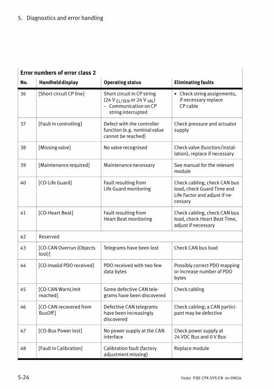
5. Diagnostics and error handling
5−24 Festo P.BE−CPX−SYS−EN en 0902e
Error numbers of error class 2
No. Eliminating faultsOperating statusHandheld display
36 [Short circuit CP line] Short circuit in CP string(24 V EL/SEN or 24 V VAL)� Communication on CP
string interrupted
· Check string assignments,if necessary replace CP cable
37 [Fault in controlling] Defect with the controllerfunction (e.g.�nominal valuecannot be reached)
Check pressure and actuatorsupply
38 [Missing valve] No valve recognised Check valve (function/instal�lation), replace if necessary
39 [Maintenance required] Maintenance necessary See manual for the relevantmodule
40 [CO−Life Guard] Fault resulting from Life Guard monitoring
Check cabling, check CAN busload, check Guard Time andLife Factor and adjust if ne�cessary
41 [CO−Heart Beat] Fault resulting from Heart Beat monitoring
Check cabling, check CAN busload, check Heart Beat Time,adjust if necessary
42 Reserved
43 [CO−CAN Overrun (Objectslost)]
Telegrams have been lost Check CAN bus load
44 [CO−Invalid PDO received] PDO received with two fewdata bytes
Possibly correct PDO mappingor increase number of PDObytes
45 [CO−CAN WarnLimit reached]
Some defective CAN tele�grams have been discovered
Check cabling
46 [CO−CAN recovered fromBusOff ]
Defective CAN telegramshave been increasingly discovered
Check cabling; a CAN partici�pant may be defective
47 [CO−Bus Power lost] No power supply at the CANinterface
Check power supply at24�VDC Bus and 0 V Bus
48 [Fault in Calibration] Calibration fault (factory adjustment missing)
Replace module

5. Diagnostics and error handling
5−25Festo P.BE−CPX−SYS−EN en 0902e
Error numbers of error class 2
No. Eliminating faultsOperating statusHandheld display
49 [Lower drop out signal] Current loop is in the lowerdrop−out range
Check the installation/para�metrisation of the actuatorSee manual for the relevantmodule
50 [Upper drop out signal] Current loop is in the upperdrop−out range
Check the installation/para�metrisation of the actuatorSee manual for the relevantmodule
51 [Sensor limit exceeded] Physical limit for a sensor ex�ceeded� Process value invalid� Possible hardware damage
� Check structure (com�pliance with module speci�fication)
� Check module for damage,if necessary replace
52 [Short circuit cold junctioncomp.]
Short circuit at cold junctioncompensation
Eliminate short circuit orcheck connected CJC sensors
53 [Open load cold junctioncomp.]
Wire break at cold junctioncompensation
Check and, if necessary, re�place the cable and connec�ted KSK sensors
54 [Calibration data incorrect] Calibration data is faulty Replace module
55 [Invalid process value] Formation of the process va�lue is invalid due to faultystructure
Check structure (compliancewith module specification)
56 ...63
Reserved
64 [Number of Modules incor�rect]
The number of modules in thecurrent CPX equipment statusdoes not equal the savedequipment status
Correct module equipmentstatus or save new one
65 ...69
Reserved
70 [CC−L: Station equip. statusincorrect]
CPX equipment status is greater than the number ofstations set
Check DIL switch setting (increase number of stations)
71 [CC−L: Bus connection lost] Bus connection interrupted Check cabling

5. Diagnostics and error handling
5−26 Festo P.BE−CPX−SYS−EN en 0902e
Error numbers of error class 2
No. Eliminating faultsOperating statusHandheld display
72 ...79
Reserved
80 [Function failure] Module−specific operativemalfunction
See manual for the relevantmodule
81 ...99
Reserved
100 [Configuration error] Fault in configuration or para�metrisation
Check configuration, correct ifnecessary or repeat commis�sioning
101 [Execution error] Fault executing a positioningjob
Check and, if necessary, correct the positioning job
102 [Record error] Fault executing a positioningrecord
Check and, if necessary, correct the positioning job
103 [Control error] Fault in control or in the para�meters of a positioning job
Check and, if necessary, correct the positioning job
104 [System error A] Fault in the process control orthe system configuration
Check system configuration orpositioning job, I/O signals orsystem status and correct asnecessary
105 [System error B] Fault in the peripherals; powersupply, operating pressure,etc.
Check peripherals, power sup�ply and operating pressure
106 [Error in valve] Fault in valve or on axis string Check valve or lines for damage, if necessary replace
107 [Controller error] Fault in the controller or driveregulator
Check controller or drive regu�lator for damage, if necessaryreplace
108 [Encoder error] Fault in measuring system oron axis string
Check measuring system or li�nes for damage, if necessaryreplace
109 [Error motor or powerstage]
Fault in the motor or powersection
Check motor or power sectionfor damage, if necessary replace

5. Diagnostics and error handling
5−27Festo P.BE−CPX−SYS−EN en 0902e
Error numbers of error class 2
No. Eliminating faultsOperating statusHandheld display
110...114
Reserved
115 [Subsystem module/channel failure]
Module/channel in a subordi�nate system has failed
Check subordinate module(function/installation), replace if necessarySee manual for the relevantmodule
Tab.�5/8: Possible faults (fault class 2)
Error numbers of error class 3
No. Handheld texts Operating status Eliminating faults
128 [Switch unit defective] Hardware defective in theswitch unit
Check module, if necessaryreplace
129 [CBUS asic not ready] Hardware defective Replace module
130 [CPU Hardware Trap] System error has occurred Replace module if Power Off/On does not remedy problem
131 [CBUS C−manager not ready]
Fault in internal communica�tion
Check CPX terminal and, if ne�cessary, replace
132 [Watchdog overflow] System error has occurred Replace module if Power Off/On does not remedy problem
133 [Remanent memory defec�tive]
Hardware defective Replace module
134 [Flash system memory defective]
Hardware defective Replace module
135 [Number of mod. pa�rams.more than 64]
Fault in internal configuration Check CPX terminal and, if necessary, replace
136 [Slave not ready] System error has occurred Replace module if Power Off/On does not remedy problem
137 [CBUS diagnostic telegram] Fault in internal communica�tion
Check CPX terminal and, if necessary, replace
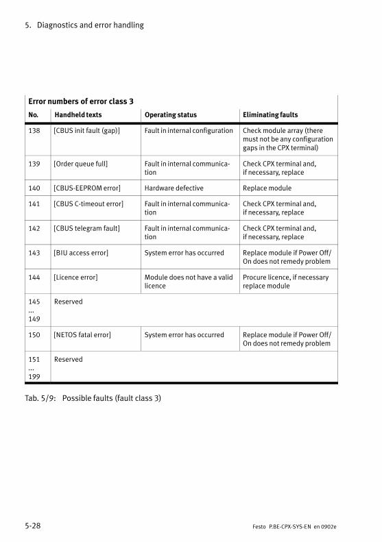
5. Diagnostics and error handling
5−28 Festo P.BE−CPX−SYS−EN en 0902e
Error numbers of error class 3
No. Eliminating faultsOperating statusHandheld texts
138 [CBUS init fault (gap)] Fault in internal configuration Check module array (theremust not be any configurationgaps in the CPX terminal)
139 [Order queue full] Fault in internal communica�tion
Check CPX terminal and, if necessary, replace
140 [CBUS−EEPROM error] Hardware defective Replace module
141 [CBUS C−timeout error] Fault in internal communica�tion
Check CPX terminal and, if necessary, replace
142 [CBUS telegram fault] Fault in internal communica�tion
Check CPX terminal and, if necessary, replace
143 [BIU access error] System error has occurred Replace module if Power Off/On does not remedy problem
144 [Licence error] Module does not have a validlicence
Procure licence, if necessaryreplace module
145...149
Reserved
150 [NETOS fatal error] System error has occurred Replace module if Power Off/On does not remedy problem
151...199
Reserved
Tab.�5/9: Possible faults (fault class 3)

5. Diagnostics and error handling
5−29Festo P.BE−CPX−SYS−EN en 0902e
Error numbers of error class 1
No. Handheld texts Operating status Eliminating faults
200 [Fault param. transfer mo�dule n]
Fault in parametrisation (parameter transfer failed)
Replace module if Power Off/On does not remedy problem
201 [Invalid field bus address] Address incorrect Check the DIL switch setting,correct if necessary
202 [Protokoll Asic not ready] Initialisation of the Chips protocol defective
Replace module if Power Off/On does not remedy problem
203 [MMI serves CPX module] MMI serves CPX modules, parametrisation is not possi�ble via the fieldbus node orFEC
Terminate MMI access
204 [Invalid setting switch unit] Invalid switch setting Check the DIL switch setting,correct if necessary
205...254
Reserved
255 [unknown fault]
Tab.�5/10: Possible faults (fault class 1)

5. Diagnostics and error handling
5−30 Festo P.BE−CPX−SYS−EN en 0902e

Technical appendix
A−1Festo P.BE−CPX−SYS−EN en 0902e
Appendix A

A. Technical appendix
A−2 Festo P.BE−CPX−SYS−EN en 0902e
Contents
A. Technical appendix A−1 . . . . . . . . . . . . . . . . . . . . . . . . . . . . . . . . . . . . . . . . . . . . .
A.1 Technical data A−3 . . . . . . . . . . . . . . . . . . . . . . . . . . . . . . . . . . . . . . . . . . . . . . . . . .
A.2 Cable length and cross−sectional area A−7 . . . . . . . . . . . . . . . . . . . . . . . . . . . . . .
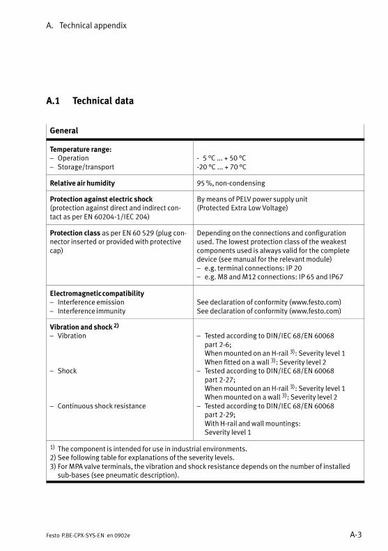
A. Technical appendix
A−3Festo P.BE−CPX−SYS−EN en 0902e
A.1 Technical data
General
Temperature range:� Operation� Storage/transport
−��5 °C ... + 50 °C−20 °C ... + 70 °C
Relative air humidity 95 %, non−condensing
Protection against electric shock(protection against direct and indirect con�tact as per EN 60204−1/IEC 204)
By means of PELV power supply unit(Protected Extra Low Voltage)
Protection class as per EN 60 529 (plug con�nector inserted or provided with protectivecap)
Depending on the connections and configurationused. The lowest protection class of the weakestcomponents used is always valid for the completedevice (see manual for the relevant module)� e.g. terminal connections: IP 20� e.g. M8 and M12 connections: IP 65 and IP67
Electromagnetic compatibility� Interference emission� Interference immunity
See declaration of conformity (www.festo.com)See declaration of conformity (www.festo.com)
Vibration and shock 2)
� Vibration
� Shock
� Continuous shock resistance
� Tested according to DIN/IEC 68/EN 60068 part 2−6;When mounted on an H−rail 3): Severity level 1When fitted on a wall 3): Severity level 2
� Tested according to DIN/IEC 68/EN 60068 part 2−27;When mounted on an H−rail 3): Severity level 1When mounted on a wall 3): Severity level 2
� Tested according to DIN/IEC 68/EN 60068 part 2−29;With H−rail and wall mountings:Severity level 1
1) The component is intended for use in industrial environments.2) See following table for explanations of the severity levels.3) For MPA valve terminals, the vibration and shock resistance depends on the number of installed
sub−bases (see pneumatic description).

A. Technical appendix
A−4 Festo P.BE−CPX−SYS−EN en 0902e
Severity level
Vibration Shock Continuous shock
1 0.15 mm path at 10 ... 58 Hz;2 g acceleration at58 ... 150 Hz
±15 g at 11 ms dura�tion; 5 shocks per direction
±15 g at 6� ms duration;1000 shocks per direction
2 0.35 mm path at 10 ... 60 Hz;5 g acceleration at60 ... 150 Hz
±30 g at 11 ms dura�tion; 5 shocks per direction
−
Operating voltage for fieldbus interface
� Nominal value� Tolerance
See manual for the specific CPX bus node
CautionShort circuits can cause damage.
Provide external fuse protection for the system supply andadditional supplies. The permissible current per pin at thesupply is:
� 7/8" plug, 4−pin: max. 10�A 1) 2)
� 7/8" plug, 5−pin: max. 8�A 1)
� M18 plug (4−pin): max. 16�A 2)
� Push−pull plug (5−pin): max. 16�A1) Limited by the specification of the connected plug con�nector. Values apply for plug connectors from Festo Acces�sories. If using third−party products, comply with the appli�cable specifications.2) Please note that with a 4−pin system supply via pin�0�V", the sum of both currents of the operating and loadvoltages flows.

A. Technical appendix
A−5Festo P.BE−CPX−SYS−EN en 0902e
Operating voltage for electronics/sensor supply
Power supply� Nominal value� Tolerance
DC 24 V (reverse polarity protected)18 ... 30 V
Current consumption Sum of the current consumption of all moduleswithout sensor supplymax. 1.5 ASee also the manual for the modules
Residual ripple 4 Vpp (within tolerance)
Load voltage of outputs
Power supply� Nominal value� Tolerance
DC 24 V (reverse polarity protected)18 ... 30 V
Current consumption Sum of all switched−on outputs (see manual foroutput modules)
Residual ripple 4 Vpp (within tolerance)

A. Technical appendix
A−6 Festo P.BE−CPX−SYS−EN en 0902e
Load voltage of the valves
Power supply� Nominal value
� Tolerance *)
DC 24 V (reverse polarity protected)
� Without pneumatics:18 ... 30 V
� With CPX−CP interface:20.4 ... 26.4 V
� With pneumatics of type MPA:18 ... 30 V
� With pneumatics of type VTSA:21.6 ... 26.4 V
� With pneumatics of type Midi/Maxi:21.6 ... 26.4 V
� With pneumatics of type CPA:20.4 ... 26.4 V
Current consumption Current consumption of the pneumatic interface:see manual for the �CPX I/O modules", type P. BE−CPX−EA−...Sum of all switched−on valve solenoid coils; seespecific Pneumatics manual
Residual ripple 4� Vpp (within tolerance)
*) The module with the lowest tolerance is always decisive for the permitted voltage tolerances (seemanual for relevant module or for relevant pneumatics).
Special technical specifications on the pneumatics used, onCPX modules, connection blocks and the CPX bus node canbe found in the relevant manuals.
A. Technical appendix
A−7Festo P.BE−CPX−SYS−EN en 0902e
A.2 Cable length and cross−sectional area
NoteIn the following section it is assumed that the reader isfamiliar with the information in the chapter �Installation" inthis manual. This section is directed exclusively at person�nel trained in electrotechnology.
A load−dependent drop in voltage occurs on the cables of theoperating voltage supply to a CPX terminal. This can causethe voltage at pin�1 or pin�2 of the operating voltage connec�tion to be outside the permitted tolerance.
Recommendation:
· Avoid long distances between the power supply unit andthe CPX terminal.
· Ascertain the most suitable cross−sectional area and themaximum cable length for the operating voltage cable inaccordance with the following formula.
NoteThe following formula assumes that the cross−sectionalareas of the operating voltage supply are the same.

A. Technical appendix
A−8 Festo P.BE−CPX−SYS−EN en 0902e
Ascertain by formula
Proceed as follows:
1. Calculate the maximum current consumption of the inputsand electronics (I1) as well as of the outputs and val�ves�(I2).
2. Ascertain the lowest voltage to be expected during opera�tion (VBmin) on the power unit. Take the following intoaccount:
· The load dependency of the power supply unit
· The fluctuations in the primary voltage
· The operating temperature of the equipment
3. Enter the values in the relevant formula. The equivalentcircuit diagram as well as the example explain the correla�tions.

A. Technical appendix
A−9Festo P.BE−CPX−SYS−EN en 0902e
Pin *)
Pin *)
Pin *)
AC
DC
RL1 VL1 RL2 VL2
RI1 RI2
RL0 VL2+VL1
0�V
VOUT/VAL
I1
I2
I0
Power supply
Terminal
Equivalent circuit diagram
L
VB
1
2
3
I1I2
I1: Electronics/sensorsI2: outputs/valves
*) See Tab.�3/4 for pin allocation
1 Line resistance (outgoing) RL1 + RL2
2 Line resistance (returning) RL0
3 L = distance (cable length)
Fig.�A/1: Equivalent circuit diagram for power supply

A. Technical appendix
A−10 Festo P.BE−CPX−SYS−EN en 0902e
Formula for maximum cable length:
L ���UBmin � UOUT�VALmin
� � A � ËCU�
{2 � l2 � l1}
Meaning
· Without pneumatics: VOUT/VALmin � 18 V With Midi/Maxi pneumatics: VOUT/VALmin � 21.6 V With CPA pneumatics: VOUT/VALmin � 20.4 V
· VBmin = minimum operating voltage supply (on the powersupply unit)
· Current I1 = current for electronics and sensors
· Current I2 = current for valves and outputs
· A = cross−sectional area (uniform e.g. 1.5 mm2)
· κ = conductance value of the cables
(uniform e.g. κCU = 56m
mm2 �)
�
Example:I1 = 1 A; I2 = 5 A; VBmin = 24 V; CPA pneumatics: VOUT/VALmin = 20.4 V;
κCU = 56m
mm2 � �
Result:L ≤ 27.49 m for A = 1.5 mm2
L ≤ 45.81 m for A = 2.5 mm2

Parameters and data of the CPX terminal
B−1Festo P.BE−CPX−SYS−EN en 0902e
Appendix B

B. Parameters and data of the CPX terminal
B−2 Festo P.BE−CPX−SYS−EN en 0902e
Contents
B. Parameters and data of the CPX terminal B−1 . . . . . . . . . . . . . . . . . . . . . . . . . . .
B.1 Access to internal parameters and data B−3 . . . . . . . . . . . . . . . . . . . . . . . . . . . . .
B.2 Description of the parameters and data B−4 . . . . . . . . . . . . . . . . . . . . . . . . . . . . .
B.2.1 Overview of the function numbers B−5 . . . . . . . . . . . . . . . . . . . . . . . . . .
B.2.2 System parameters B−8 . . . . . . . . . . . . . . . . . . . . . . . . . . . . . . . . . . . . . .
B.2.3 Module parameters B−15 . . . . . . . . . . . . . . . . . . . . . . . . . . . . . . . . . . . . . .
B.2.4 Diagnostic memory parameters B−23 . . . . . . . . . . . . . . . . . . . . . . . . . . . .
B.2.5 Diagnostic memory data B−29 . . . . . . . . . . . . . . . . . . . . . . . . . . . . . . . . . .
B.2.6 System diagnostic data B−32 . . . . . . . . . . . . . . . . . . . . . . . . . . . . . . . . . . .
B.2.7 Module diagnostic data B−34 . . . . . . . . . . . . . . . . . . . . . . . . . . . . . . . . . .
B.2.8 System data B−36 . . . . . . . . . . . . . . . . . . . . . . . . . . . . . . . . . . . . . . . . . . . .
B.2.9 Module data B−42 . . . . . . . . . . . . . . . . . . . . . . . . . . . . . . . . . . . . . . . . . . . .

B. Parameters and data of the CPX terminal
B−3Festo P.BE−CPX−SYS−EN en 0902e
B.1 Access to internal parameters and data
The CPX terminal permits access to internally saved data andparameters. The ways in which you can access these data andparameters depend on the fieldbus protocol used. Forexample access can be made via:
� The plug−in module or scanner/bus master; e.g. for guar�anteeing the desired parametrisation of the CPX terminalin the start−up phase or after fieldbus interruptions
� Fieldbus−specific configurators, e.g. during the commis�sioning phase or during a search for faults
� The user program in the higher−order PLC/IPC, e.g. formodifying parameters or system features during oper�ation
� The handheld, e.g. during the commissioning phase orduring a search for faults
� The I/O diagnostic interface, e.g. for reading out diagnos�tic data.
Data can be read. Parameters can be read and modified.
Only read access to parameters and data by means of therelevant function number is possible via the I/O diagnosticinterface (see section 5.2.2).

B. Parameters and data of the CPX terminal
B−4 Festo P.BE−CPX−SYS−EN en 0902e
B.2 Description of the parameters and data
A distinction is made between the following parameters anddata:
Parameters Description
System para�meters
Determine global system functions for thecomplete CPX terminal, e.g.:� Diagnostic monitoring� System start etc.
Module para�meters
Determine module−specific and channel−spe�cific functions for the relevant module, e.g.:� Input debounce time� Signal extension times etc.
Diagnostic mem�ory parameters
Determine the working method of the diagnos�tic memory.
Tab.�B/1: CPX parameters
Data Description
System diagnosticdata
Global information on the system status(e.g.�common diagnostic message)
Module diagnosticdata
Information on fault finding (e.g. error number,number of the first faulty channel etc.)
Diagnostic mem�ory data
Entries in the diagnostic memory (max. 40)
System data Information on global system settings
Module data Serial number, revision code and module codeof the modules used
Tab.�B/2: CPX data

B. Parameters and data of the CPX terminal
B−5Festo P.BE−CPX−SYS−EN en 0902e
B.2.1 Overview of the function numbers
Function no. 1) CPX data and CPX parameters See
0 CPX operating mode (system data) Tab.�B/48
0 CPX expansion (system data) Tab.�B/49
0 Handheld (system data) Tab.�B/50
0 Force mode (system data) Tab.�B/51
0 System start (system data) Tab.�B/52
1 Fail safe (system data) Tab.�B/53
1 System idle mode (system data) Tab.�B/54
2 Monitoring CPX terminal (system data) Tab.�B/55
16 + 16m + 0 Module code (module data) Tab.�B/59
16 + 16m + 13 Revision code (module data) Tab.�B/60
784 + m * 4 + 0784 + m * 4 + 1784 + m * 4 + 2784 + m * 4 + 3
Serial number (module data) Tab.�B/62
1936 Status bits (system diagnostic data) Tab.�B/39
1937 Module number and diagnostic status (system diagnostic data) Tab.�B/40
1938 Error number (system diagnostic data) Tab.�B/41
2008 + m * 4 + 0 Number of the first faulty channel (module diagnostic data) Tab.�B/43
2008 + m * 4 + 1 Module error number (module diagnostic data) Tab.�B/44
2008 + m * 4 + 2 Information 2 (module diagnostic data) Tab.�B/45
2008 + m * 4 + 3 Information 3 (module diagnostic data) Tab.�B/46
3480 Entries remanent with Power ON (diagnostic memory parameters) Tab.�B/24
3480 Run/stop filter 1 (diagnostic memory parameters) Tab.�B/25
1) m = module number (counting on the modules from left to right, beginning with 0)

B. Parameters and data of the CPX terminal
B−6 Festo P.BE−CPX−SYS−EN en 0902e
Function no. 1) SeeCPX data and CPX parameters
3482 Number of entries in the diagnostic memory (diagnostic memorydata)
Tab.�B/34
3483 Overrun (diagnostic memory data) Tab.�B/35
3483 Status (diagnostic memory data) Tab.�B/36
3484 Run/stop filter 2 (diagnostic memory parameters) Tab.�B/26
3484 Fault end filter (diagnostic memory parameters) Tab.�B/27
3484 Error number filter (diagnostic memory parameters) Tab.�B/28
3484 Module/channel filter (diagnostic memory parameters) Tab.�B/29
3485 Module number MN (diagnostic memory parameters) Tab.�B/30
3486 Channel number KN (diagnostic memory parameters) Tab.�B/31
3487 Error number FN (diagnostic memory parameters) Tab.�B/32
3488 + n Diagnostic memory data (diagnostic memory data) Tab.�B/37
4401 Monitoring (system parameters) Tab.�B/4
4402 Fail safe (system parameters) Tab.�B/5
4402 Force mode (system parameters) Tab.�B/6
4402 System idle mode (system parameters) Tab.�B/7
4402 System start (system parameters) Tab.�B/8
4402 Analogue process value display (data format) Tab.�B/9
4828 + m * 64 + 0 Monitoring the CPX module (module parameter) Tab.�B/12
4828 + m * 64 + 1 Behaviour after short circuit/overload (module parameter) Tab.�B/13
4828 + m * 64 + 1 Input debouncing time (module parameters) Tab.�B/14
4828 + m * 64 + 1 Signal extension time (module parameters) Tab.�B/15
4828 + m * 64 + 3 Data format for analogue value of inputs (module parameters) Tab.�B/16
4828 + m * 64 + 3 Data format for analogue value of outputs (module parameters) Tab.�B/17
1) m = module number (counting on the modules from left to right, beginning with 0)

B. Parameters and data of the CPX terminal
B−7Festo P.BE−CPX−SYS−EN en 0902e
Function no. Channel−specific module parameters See
− 1) Signal extension channel x Tab.�B/18
− 1) Wire break monitoring, channel x Tab.�B/19
− 2) Fail safe channel x Tab.�B/20
− 2) Idle mode channel x Tab.�B/21
− 2) Forcing channel x Tab.�B/22
1) Function number, see manual for CPX modules2) Access is protocol−specific (see manual for CPX bus node)
Function no. Fieldbus−specific system data See
− Number of input bytes (Rx size) 1) Tab.�B/56
− Number of output bytes (Tx size) 1) Tab.�B/57
1) Only relevant with certain fieldbus protocols (see manual for CPX bus node)

B. Parameters and data of the CPX terminal
B−8 Festo P.BE−CPX−SYS−EN en 0902e
B.2.2 System parameters
The system parameters refer to global functions of the CPXterminal. The following system parameters are available:
Function no. System parameters
4400 Reserved
4401 Monitoring (active/inactive)
4402 Fail safe (reaction to communication faults)
4402 Force mode (enable/block force)
4402 System Idle mode (reaction when changing into the Idle status) 1)
4402 System start
4402 Analogue process value display (data format)1)
1) Only relevant with certain fieldbus protocols (see manual for CPX bus node)
Tab.�B/3: Overview � system parameters
[........] The data and parameters which appear in English on thehandheld are shown in square brackets in this manual, e.g. [Debounce time].
.

B. Parameters and data of the CPX terminal
B−9Festo P.BE−CPX−SYS−EN en 0902e
System parameter: Monitoring
Function no. 4401
Description The monitoring of short circuit/overload and undervoltage for the complete CPXterminal can be activated or deactivated (suppressed). Active monitoring causesthe following. An error registered by the module will be:� Sent to the higher−order fieldbus master� Entered, if applicable, in the diagnostic memory (depending on filter settings)� Entered in the module diagnostic data and, if applicable, in the status bits� Displayed by the module common error LED� Displayed by the red SF−LED on the CFX bus node
Bit0
MonitoringDescriptionShort circuit/overload in sensor supply (SCS)
[Monitor]
[Monitor SCS]
1 Short circuit/overload at the outputs (SCO) [Monitor SCO]
2 Undervoltage at outputs (VOUT) [Monitor Vout]
3 Undervoltage of valves (VVAL) [Monitor Vval]
4 Short circuit at valves (SCV) [Monitor SCV]
5...7 Reserved
Values 1 = active (presetting)0 = inactive
[Active][Inactive]
Note Monitoring can also be set separately for each module (see module parametermonitoring CPX module).The method of operation of the channel fault LED remains unaltered.
Tab.�B/4: Monitoring short circuit/overload/undervoltage
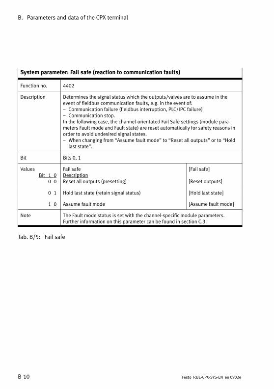
B. Parameters and data of the CPX terminal
B−10 Festo P.BE−CPX−SYS−EN en 0902e
System parameter: Fail safe (reaction to communication faults)
Function no. 4402
Description Determines the signal status which the outputs/valves are to assume in theevent of fieldbus communication faults, e.g. in the event of:� Communication failure (fieldbus interruption, PLC/IPC failure)� Communication stop.In the following case, the channel−orientated Fail Safe settings (module para�meters Fault mode and Fault state) are reset automatically for safety reasons inorder to avoid undesired signal states.� When changing from �Assume fault mode" to �Reset all outputs" or to �Hold
last state".
Bit Bits 0, 1
ValuesBit 1 0
0 0
Fail safeDescriptionReset all outputs (presetting)
[Fail safe]
[Reset outputs]
0 1 Hold last state (retain signal status) [Hold last state]
1 0 Assume fault mode [Assume fault mode]
Note The Fault mode status is set with the channel−specific module parameters.Further information on this parameter can be found in section C.3.
Tab.�B/5: Fail safe

B. Parameters and data of the CPX terminal
B−11Festo P.BE−CPX−SYS−EN en 0902e
System parameter: Force mode
Function no. 4402
Description Determines for the complete CPX terminal whether the Force function is blockedor enabled.By changing this parameter, the channel−orientated Force settings (module para�meters Force mode and Force state) are reset automatically for safety reasons inthe following cases in order to avoid undesired signal states:� When modified via the Handheld: When changed from �enable" to �disabled".� When modified via the fieldbus: When changed from �disabled" to �enabled".
Bit Bits 2, 3
ValuesBit 3 2
0 0
Force modeDescriptionDisabled (presetting)
[Force mode]
[Disabled]
0 1 Enabled [Enabled]
Note Force signals have precedence over Fail Safe signals.
Tab.�B/6: Force mode

B. Parameters and data of the CPX terminal
B−12 Festo P.BE−CPX−SYS−EN en 0902e
System parameter: System Idle mode
Function no. 4402
Description Establishes which signal status outputs/valves are to assume when the CPXterminal switches into the Idle state.In the following case, the channel−orientated Idle mode settings (module para�meters Idle mode and Idle state) are reset automatically for safety reasons inorder to avoid undesired signal states.� When changing from �Idle fault mode" to �Reset all outputs" or to �Hold last
state".
Bit Bits 4, 5
ValuesBit 5 4
0 0
System Idle modeDescriptionReset all outputs (presetting)
[Idle mode]
[Reset outputs]
0 1 Hold last state (retain signal status) [Hold last state]
1 0 Assume Idle mode Assume idle mode]
Note Only relevant for certain fieldbus protocols Explanations on this can be found inthe manual for the relevant CPX bus node.
Tab.�B/7: Idle mode

B. Parameters and data of the CPX terminal
B−13Festo P.BE−CPX−SYS−EN en 0902e
System parameter: System start 1)
Function no. 4402
Description With this parameter you can determine the start−up reaction of the CPX terminaland save all current parameter settings and the current CPX equipment status.
Bit Bit 6
ValuesBit 6
System start *)Description
[System start]
0 System start with default parametrising (factory set�ting) and current CPX equipment status; external para�metrising is possible (presetting)
[Default parameters]
1 System start with saved parametrising and saved CPXequipment status; parameters and CPX equipmentstatus are saved remanently; external parametrising isblocked; the M−LED on the CPX bus node lights up.
[Saved parameters]
Note If bit 6 is set to 1, the current parameter settings will be �frozen" (write−protec�ted) and the current CPX equipment status will be saved, except for bit 6 itselfand the module parameter �Force channel X."Recommendation: Select �System start with default parametrising and currentCPX equipment status." The desired parametrising can then be created in thestart−up phase or after fieldbus interruptions e.g. by the plug−in module or thescanner/bus master (depending on the fieldbus used). If �System start withdefault parametrising and current CPX equipment status" is active, the factorysettings for all module and system parameters will become valid after Power On.
1) This parameter does not exist with the CPX−FEC in the operating modes Stand Alone and RemoteController (control function active).
Tab.�B/8: System start

B. Parameters and data of the CPX terminal
B−14 Festo P.BE−CPX−SYS−EN en 0902e
System parameter: Analogue process value display (data format)1)
Function no. 4402
Description Switches the data format for displaying analogue process values. This is a special parameter for certain CPX bus nodes only (CPX−FB13, FB33/34).
Bit Bit 7
ValuesBit 7
Analogue process value displayDescription
[Analogue data format]
0 INTEL byte sequence (LSB−MSB, factory setting):Process values are displayed in the Intel format (lowestvalue bit on the left, highest value bit on the right)
[Intel format]
1 MOTOROLA byte sequence (MSB−LSB):Process values are displayed in the Motorola format(highest value bit on the left, lowest value bit on theright)
[Motorola format]
Note 1) This is a special parameter for certain CPX bus nodes only (CPX−FB13, FB33/34)
Tab.�B/9: Analogue process value display

B. Parameters and data of the CPX terminal
B−15Festo P.BE−CPX−SYS−EN en 0902e
B.2.3 Module parameters
Module parameters refer to module−specific or channel−spe�cific functions. 64 bytes are available for parameters in eachmodule. Detailed information on the module parameters,which are supported by the module used, can be found in themanual for the relevant module. There you will also find in�formation on possible parameter values and their preset�tings.
Function number 1) Module parameters
4828 + m * 64 + 0 Monitoring the CPX module
4828 + m * 64 + 1 Reaction after short circuit/overload
4828 + m * 64 + 1 Input debounce time
4828 + m * 64 + 1 Signal stretching time
4828 + m * 64 + 3 Data format analogue value inputs
4828 + m * 64 + 3 Data format analogue value outputs
1) m = module number (counting on the modules from left to right, beginning with 0)
Tab.�B/10:Overview of module parameters for module−specific functions
Function no. Example of some channel−specific module parameters
4828 + m * 64 + 6 Signal extension channel x
− 1) Monitoring wire fracture channel X
− 2) Fail safe channel x
− 2) Idle mode channel x
− 2) Forcing channel x
1) Function number, see manual for CPX modules2) Access is protocol−specific (see manual for CPX bus node)
Tab.�B/11:Overview − Example of some channel−specific module parameters

B. Parameters and data of the CPX terminal
B−16 Festo P.BE−CPX−SYS−EN en 0902e
Module parameter: Monitoring of the CPX module
Modules Depending on the monitoring function for modules with digital and analogueinputs and outputs (see description on the respective module)
Function no. 4828 + m * 64 + 0 m = module number (0 ... 47)
Description Monitoring of the possible faults can be activated or deactivated (suppressed)for each module independently. Active monitoring causes the following. Thefault is:� Sent to the CPX bus node� Displayed by the module common error LED.
Bit0
MonitoringDescriptionShort circuit/overload in sensor supply (SCS)
[Monitor]
[Monitor SCS]
1 Short circuit/overload at the outputs (SCO) [Monitor SCO]
2 Undervoltage of outputs/valves (VOUT/VAL) [Monitor Vout/val]
3 Short circuit at the valve (SCV) [Monitor SCV]
4 Reserved −
5 Reserved −
6 Reserved −
7 Monitoring parametrisation faults [Monitor parameters]
Values 1 = active (presetting)0 = inactive
[Active][Inactive]
Note Monitoring can also be set for the complete CPX terminal (see �System parame�ter monitoring").
Tab.�B/12:Monitoring the CPX module
For parametrising the �Monitoring CP modules" on the CPX−CP interface see the manual for the CPX−CP interfacetype P. BE−CPX−CP−....

B. Parameters and data of the CPX terminal
B−17Festo P.BE−CPX−SYS−EN en 0902e
Module parameter: Behaviour after short circuit/overload
Modules Depending on the function for modules with digital and analogue inputs andoutputs (see description on the respective module)
Function no. 4828 + m * 64 + 1 m = module number (0 ... 47)
Description Determines after a short circuit in the sensor supply or the outputs whether thepower is to remain switched off or whether it is to be switched on again automa�tically.
Bit013
Behaviour after short circuit/overloadDescriptionShort circuit/overload in sensor supply (SCS)Short circuit/overload at the outputs (SCO)Short circuit/overload at the analogue signal
[Behaviour after]
[Behaviour after SCS][Behaviour after SCO][Behaviour after SCA]
Values 0 = Voltage/current remains switched off1 = Switch voltage/current on again
[Leave switched off ][Resume]
Note With the setting �Voltage/current remains switched off", you must switch thepower off/on or set/reset the relevant signals in order to apply power again.Check which setting is necessary for reliable operation of your system. Furtherinformation can be found in the manual for the CPX I/O modules.
Tab.�B/13: Behaviour after short circuit/overload

B. Parameters and data of the CPX terminal
B−18 Festo P.BE−CPX−SYS−EN en 0902e
Module parameter: Input debounce time
Modules For modules with digital inputs (see manual for the module)
Function no. 4828 + m * 64 + 1 m = module number (0 ... 47)
Description Determines when a change of edge of the sensor signal on this module is to beaccepted as a logical input signal.
Bit Bits 4, 5
Typical valuesBit 5 4
0 00 11 01 1
Input debounce timeDescription0.1 ms3 ms (typical presetting)10 ms20 ms
[Debounce time]
Note Input debounce times are specified in order to eliminate interfering changes ofsignal edge during switching procedures (bouncing of the input signal). Furtherinformation on this parameter can be found in section C.1.
Tab.�B/14: Input debounce time

B. Parameters and data of the CPX terminal
B−19Festo P.BE−CPX−SYS−EN en 0902e
Module parameter: Signal extension time
Modules For modules with digital inputs (see manual for the module)
Function no. 4828 + m * 64 + 1 m = module number (0 ... 47)
Description Determines the signal extension time for the relevant module. Signal statesaccepted as logical input signals usually remain valid at least until the specifiedsignal extension time (minimum signal duration) has expired. Changes of edgewithin the extension time are ignored.
Bit Bits 6, 7
Typical valuesBit 7 6
0 00 11 01 1
Signal extension timeDescription0.5 ms15 ms (typical presetting)50 ms100 ms
[Signal extension]
Note There is a danger that short signals are not �recognised" due to long cycle timesof the higher−order controller. In order that such signals are taken into conside�ration in the control sequence, a signal extension time can be specified (seesection C.2). The signal extension time can be activated channel−by−channel (seechannel−specific module parameters).
Tab.�B/15: Signal extension time
Module parameter: Data format for analogue value of inputs
Modules For modules with analogue inputs (see manual for the module)
Function no. 4828 + m * 64 + 3 m = module number (0 ... 47)
Description Determines the data format with which the relevant analogue values are pro�cessed internally.
Bit Bits 0, 1
Values Data format for analogue value of inputsSee manual for the relevant analogue module
[Input format]
Note The choice of data format depends on the fieldbus or fieldbus master used andsimplifies evaluation of the analogue values.
Tab.�B/16: Data format for analogue value of inputs

B. Parameters and data of the CPX terminal
B−20 Festo P.BE−CPX−SYS−EN en 0902e
Module parameter: Data format for analogue value of outputs
Modules For modules with analogue outputs (see manual for the module)
Function no. 4828 + m * 64 + 3 m = module number (0 ... 47)
Description Determines the data format with which the relevant analogue values are proces�sed internally.
Bit Bits 4, 5
Values Data format for analogue value of outputsSee manual for the relevant analogue module
[Output format]
Note The choice of data format depends on the fieldbus or fieldbus master used andsimplifies evaluation of the analogue values.
Tab.�B/17: Data format for analogue value of outputs
Example of some channel−specific module parameters
Module parameter: Signal extension channel x
Modules For modules with digital inputs (see manual for the module)
Function no. 4828 + m * 64 + 6 m = module number (0 ... 47)
Description Determines whether the signal extension for the relevant I−channel is to be enabled or blocked.
Bit Bit 0 ... 7 (channel 0 ... 7)
Values Signal extension input channel ...0 = blocked1 = enabled
[Signal extension Inp Ch ...][Disabled][Enabled]
Note The signal extension time can be specified separately for each module (see function no. 4828 + n; n = m * 64 + 1).
Tab.�B/18: Signal extension channel x (channel−specific)

B. Parameters and data of the CPX terminal
B−21Festo P.BE−CPX−SYS−EN en 0902e
Module parameter: Monitoring wire fracture channel x (only for CPA pneumatics)
Modules For CPA pneumatic interface (see description for pneumatic interface)
Function no.− Channel 0 ... 7:− Channel 8 ... 15:− Channel 16 ... 23:− Channel 24 ... 31:
4828 + m * 64 + 6 m = module number (0 ... 47)4828 + m * 64 + 74828 + m * 64 + 84828 + m * 64 + 9
Description Determines whether Monitoring Wire Fracture for the relevant channel isactive or inactive (CPA: Channel 0 ... 21).
Monitoring wire fracture output channel ...0 = inactive1 = active
[Monitor open circuit Out CH ...][Inactive][Active]
Note With Monitoring Wire Fracture, a missing valve or a wire fracture (connectionfault between the pneumatic interface and the valve coil) is recognised.
Tab.�B/19:Monitoring wire fracture channel x (channel−specific)
Module parameter: Fail safe channel x
Modules For modules with digital and analogue outputs (see manual for the module)
Function no. Access to these module parameters is made via protocol−specific functions (seethe CPX bus node description).
Description Fault mode channel x: Hold last stateFault state (presetting)
Fault state channel x: Set outputReset output (presetting)
Note With the aid of fail safe parametrisation, the signal status which the outputs areto assume in the event of field bus communication faults can be specified (seealso section C.3).
Tab.�B/20: Fail Safe channel x (channel−specific)

B. Parameters and data of the CPX terminal
B−22 Festo P.BE−CPX−SYS−EN en 0902e
Module parameter: Idle mode channel x
Modules For modules with digital and analogue outputs (see manual for the module)
Function no. Access to these module parameters is made via protocol−specific functions (seethe CPX bus node description).
Description Only relevant for certain fieldbus protocols.Idle mode channel x: Hold last state
Idle state (presetting)Idle state channel x: Set output
Reset output (presetting)
Note With the aid of Idle mode parametrisation, the signal status which the outputs/valves are to assume during a change into the Idle status can be determined(see also section C.3.3).
Tab.�B/21: Idle mode channel x (channel−specific)
Module parameter: Force channel x
Modules For modules with digital and analogue inputs and outputs (see manual for themodule)
Function no. Access to these module parameters is made via protocol−specific functions (seethe CPX bus node description).
Description Force mode of inputs channel x: blocked (presetting)Force state
Force state of inputs channel x: Set signalReset signal (presetting)
Force mode of outputs channel x: blocked (presetting)Force state
Force state of outputs channel x: Set signalReset signal (presetting)
Note The function Force permits the manipulation of signal states independent ofactual operating conditions (see also section C.3.1).
Tab.�B/22: Force channel x (channel−specific)
For additional channel−specific module parameters as well asdetailed information, see the manual for the relevant module.

B. Parameters and data of the CPX terminal
B−23Festo P.BE−CPX−SYS−EN en 0902e
B.2.4 Diagnostic memory parameters
The working method of the diagnostic memory can beadapted to individual requirements by means of the diagnos�tic parameters.
The diagnostic memory parameters retain their last settingafter power off/on. They are saved securely against poweroutages. The parameter values marked with presetting corre�spond to the factory condition. Further information on theworking method of the diagnostic memory can be found insection C.4.
The following parameters can be influenced:
Function no. Diagnostic memory parameters
3480 Entries remanent with power ON
3480 Run/stop filter 1
3484 Run/stop filter 2
3484 Fault end filter
3484 Error number filter
3484 Module/channel filter
3485 Module number MN
3486 Channel number CN
3487 Error number FN
Tab.�B/23:Overview � Diagnostic parameters

B. Parameters and data of the CPX terminal
B−24 Festo P.BE−CPX−SYS−EN en 0902e
Diagnostic memory parameters: Entries remanent with Power on
Function no. 3480
Description Determines whether the contents of the diagnostic memory are to be retainedafter new Power on or whether they are to be deleted.
Bit 0 Entries remanent with new power ON [Entries remanent atPower ON]
Values 1 = inactive0 = active (presetting)
[Inactive][Active]
Note The diagnostic memory will be deleted if the mode is changed.
Tab.�B/24: Entries remanent with Power on
Diagnostic memory parameter: Run/stop filter 1
Function no. 3480
Description Diagnostic memory filter with which you can determine whether the first 40 errors or the last 40 errors are to be saved.
Bit Bit 1
ValuesBit 1
0
1
Run/stop filter 1:
Save the first 40 entries (stop after 40 entries);Save the last 40 entries (overwrite old entries, pre�setting)
[Run/Stop 1]
[Save the first 40 entries]
[Save the last 40 entries]
Note The diagnostic memory will be deleted if the mode is changed.
Tab.�B/25: Run/stop filter 1

B. Parameters and data of the CPX terminal
B−25Festo P.BE−CPX−SYS−EN en 0902e
Diagnostic memory parameter: Run/stop filter 2
Function no. 3484
Description Diagnostic memory filter with which you can determine when the registering oferrors is to be started or stopped.
Bit Bit 0...2
Values
Bit 2 1 00 0 0
Run/stop filter 2MN = module number, CN = channel number, FN = error number
DescriptionRun/stop filter 2 inactive (presetting)
[Run/Stop 2]
[Inactive]
0 0 1 Register up to the defined FN [Rec. up to def. FN]
0 1 0 Register up to the defined FN + MN [Rec. up to def. FN + MN]
0 1 1 Register up to the defined FN + MN + CN [Rec. up to def. FN + MN + CN]
1 0 0 Register as from the defined FN [Rec. as of def. FN]
1 0 1 Register as from the defined FN + MN [Rec. as of def. FN + MN]
1 1 0 Register as from the defined FN + MN + CN [Rec. as of def. FN + MN + CN]
1 1 1 Reserved −
Note The numbers are determined by means of the diagnostic memory parameters�Module, channel and error numbers" (function nos. 3485....3487).
Tab.�B/26: Run/stop filter 2

B. Parameters and data of the CPX terminal
B−26 Festo P.BE−CPX−SYS−EN en 0902e
Diagnostic memory parameter: Fault end filter
Function no. 3484
Description Diagnostic memory filter with which you can determine whether running faultsare to be registered or not.
Bit Bit 3
ValuesBit 3
0
1
Fault end filterDescriptionRegister running faults (end of fault) (filter inactive,presetting)Do not register running faults (end of fault) (filteractive)
[Fault end filter]
[Rec. outg. faults]
[Do not rec. outg. faults]
Note By registering the outgoing fault, you can ascertain how long the fault has existed. Incoming and running faults each represent one entry. With runningfaults the fault number �0" is entered. Maximum 40 entries are saved together.
Tab.�B/27: Fault end filter
Diagnostic memory parameter: Error number filter
Function no. 3484
Description With this diagnostic memory filter you can:� Suppress the registering of a desired fault message� Register exclusively a desired fault message
Bit Bits 4, 5
Values
Bit 5 40 00 11 01 1
Error number filterFN = error numberDescriptionError number filter inactive (presetting)Register only defined FNDo not register defined FNReserved
[Fault numbers filter]
[Inactive][Rec. only def. FN][Do not rec. def. FN]−
Note The error number is determined by means of the diagnostic memory parameter�Error number" (function no. 3487).
Tab.�B/28: Error number filter

B. Parameters and data of the CPX terminal
B−27Festo P.BE−CPX−SYS−EN en 0902e
Diagnostic memory parameter: Module/channel filter
Function no. 3484
Description With this diagnostic memory filter, the registering of faults of other modules orchannels can be suppressed in order that faults in a particular module or chan�nel can be analysed.
Bit Bits 6, 7
Values
Bit 7 60 00 11 01 1
Module/channel filterFN = error numberDescriptionModule/channel filter inactive (presetting)Register only the FN of a moduleRegister only the FN of a channelReserved
[Module/channel filter]
[Inactive][Rec. FN of a mod.][Rec, FN of a ch.]
Note The numbers are determined by means of the diagnostic memory parameters�Module and channel numbers" (function nos. 3485...3486).
Tab.�B/29:Module/channel filter
Diagnostic memory parameter: Module number (MN)
Function no. 3485
Description Module number for the diagnostic memory filter
Bit 0...7 (1 byte)
Values Module number (MN)0...47 Module number (0 = presetting)
[Module number MN]
Note Is only effective if an appropriate diagnostic memory filter is active.
Tab.�B/30:Module number (MN)

B. Parameters and data of the CPX terminal
B−28 Festo P.BE−CPX−SYS−EN en 0902e
Diagnostic memory parameter: Channel number (CN)
Function no. 3486
Description Channel number for the diagnostic memory filter
Bit 0...7 (1 byte)
Values Channel number (CN)0...63 Channel number (0 = presetting)
[Channel number CN]
Note Is only effective if an appropriate diagnostic memory filter is active.
Tab.�B/31: Channel number (CN)
Diagnostic memory parameter: Fault number (FN)
Function no. 3487
Description Fault number for the diagnostic memory filter
Bit 0...7 (1 byte)
Values Fault number (FN)0...255 Fault number (0 = presetting)
[Fault number FN]
Note Is only effective if an appropriate diagnostic memory filter is active.
Tab.�B/32: Fault number (FN)

B. Parameters and data of the CPX terminal
B−29Festo P.BE−CPX−SYS−EN en 0902e
B.2.5 Diagnostic memory data
The following diagnostic memory data is available:
Function no. Diagnostic memory data
3482 Number of entries in the diagnostic memory
3483 Overflow
3483 Status
3488 + n Diagnostic memory data (10 bytes per diagnostic entry, max. 40 entries)
Tab.�B/33:Overview � Diagnostic memory data
Diagnostic memory data: Number of entries in the diagnostic memory
Function no. 3482
Description Specifies the number of entries in the diagnostic memory
Bit 0...7 (1 byte)
Values Number of entries in the diagnostic memory0 ... 40
[recorded faults ...]
Note Can be used as a loop counter if the complete diagnostic memory is to be readout by PLC program.
Tab.�B/34:Number of entries in the diagnostic memory

B. Parameters and data of the CPX terminal
B−30 Festo P.BE−CPX−SYS−EN en 0902e
Diagnostic memory data: Overflow
Function no. 3483
Description Specifies whether the diagnostic memory has overflowed.
Bit 0
ValuesBit 0
01
OverflowDescriptionNo overflowOverflow
[no overflow][overflow]
Note The overflow is displayed when the first 40 faults are registered as well as whenthe last 40 faults are registered. Overflow means that more than 40 faults haveoccurred.
Tab.�B/35:Overflow
Diagnostic memory data: Status
Function no. 3483
Description Specifies whether the error display is active or inactive.
Bit 1
ValuesBit 1
01
DescriptionRegistering activeRegistering inactive
[Recording active][Recording inactive]
Note The fault registering can be stopped and started with the run/stop filters.
Tab.�B/36: Status
Structure of the diagnostic memory
The diagnostic memory contains up to 40 diagnostic entries.A diagnostic entry consists of 10 bytes. The first five bytescontain information on the fault time. The last five bytes con�tain information on the fault. The structure of the diagnosticentries is displayed in Tab.�B/37.
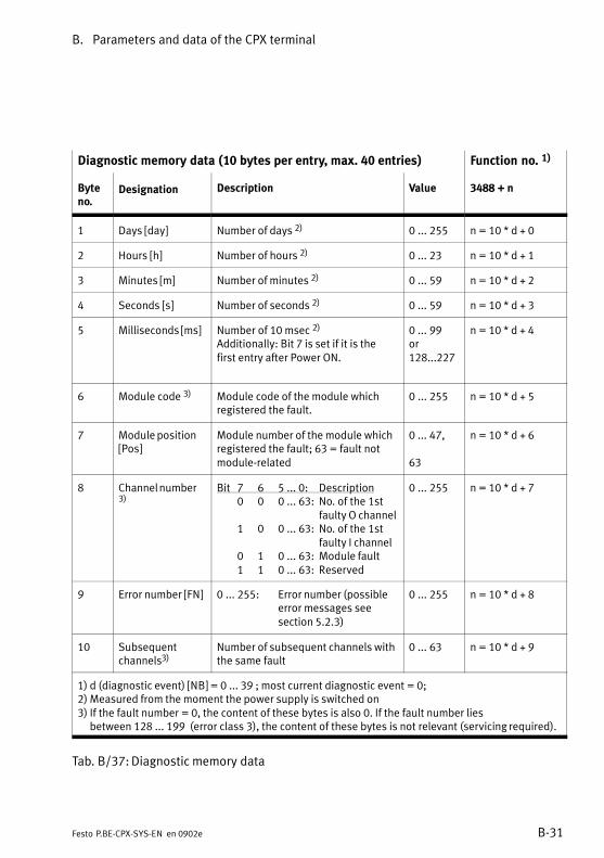
B. Parameters and data of the CPX terminal
B−31Festo P.BE−CPX−SYS−EN en 0902e
Diagnostic memory data (10 bytes per entry, max. 40 entries) Function no. 1)
Byteno.
Designation Description Value 3488 + n
1 Days [day] Number of days 2) 0 ... 255 n = 10 * d + 0
2 Hours [h] Number of hours 2) 0 ... 23 n = 10 * d + 1
3 Minutes [m] Number of minutes 2) 0 ... 59 n = 10 * d + 2
4 Seconds [s] Number of seconds 2) 0 ... 59 n = 10 * d + 3
5 Milliseconds [ms] Number of 10 msec 2)
Additionally: Bit 7 is set if it is thefirst entry after Power ON.
0 ... 99or128...227
n = 10 * d + 4
6 Module code 3) Module code of the module which registered the fault.
0 ... 255 n = 10 * d + 5
7 Module position[Pos]
Module number of the module whichregistered the fault; 63 = fault notmodule−related
0 ... 47,
63
n = 10 * d + 6
8 Channel number3)
Bit 7 6 5 ... 0: Description0 0 0 ... 63: No. of the 1st
faulty O channel1 0 0 ... 63: No. of the 1st
faulty I channel0 1 0 ... 63: Module fault1 1 0 ... 63: Reserved
0 ... 255 n = 10 * d + 7
9 Error number [FN] 0 ... 255: Error number (possibleerror messages see section 5.2.3)
0 ... 255 n = 10 * d + 8
10 Subsequentchannels3)
Number of subsequent channels withthe same fault
0 ... 63 n = 10 * d + 9
1) d (diagnostic event) [NB] = 0 ... 39 ; most current diagnostic event = 0;2) Measured from the moment the power supply is switched on3) If the fault number = 0, the content of these bytes is also 0. If the fault number lies
between 128 ... 199 (error class 3), the content of these bytes is not relevant (servicing required).
Tab.�B/37:Diagnostic memory data

B. Parameters and data of the CPX terminal
B−32 Festo P.BE−CPX−SYS−EN en 0902e
B.2.6 System diagnostic data
The following system diagnostic data is available:
Function no. System diagnostic data
1936 Status bits (error type and error source)
1937 Module number and diagnostic status
1938 Error number
Tab.�B/38:Overview − Diagnostic data
System diagnostic data: Status bits
Function no. 1936
Description The 8 status bits display common diagnostic messages (global error messages).Bits 0...3 display the source of the fault and bits 4...7 display the type of thefault.
Bit Status bitsFault source: Bit 0: valve
Bit 1: outputBit 2: inputBit 3: analogue/function
module*)Fault type: Bit 4: undervoltage
Bit 5: short circuit/overloadBit 6: wire fractureBit 7: other faults
[System diagnostics][Valve][Output][Input][Analogue/function module]
[Undervoltage][Short circuit/overload][Wire fracture][Other error]
Values 1 = there is a fault; 0 = no fault
*) Function modules are also known as technology modules (e.g. CPX−CP interface).
Tab.�B/39: Status bits

B. Parameters and data of the CPX terminal
B−33Festo P.BE−CPX−SYS−EN en 0902e
System diagnostic data: Module number and diagnostic status
Function no. 1937
Description Function no. 1937 specifies whether there is diagnostic data and contains, whereapplicable, the number of the first module on which a fault has occurred. Withthe aid of the module number of the faulty module you can ascertain the functionnumbers of the relevant diagnostic data.
Bit Bit 0 ... 5: Module number of the firstfaulty module
Bit 6: Diagnostic statusBit 7: Reserved
[First faulty module]
Values Bits 0...5: 0...47 (module number)Bit 6: 1 = there is diagnostic data
0 = there is no diagnostic data
Note Function no. 1938 contains the relevant error number.See Fig.�5/7 and Fig.�5/9 for examples.
Tab.�B/40:Module number and diagnostic status
System diagnostic data: Error number
Function no. 1938
Description Contains the current error number
Bit Bit 0 ... 7 : error number [Fault number]
Values 0 ... 255 : error number
Note See section 5.2.3 for possible error messages.Function no. 1937 specifies whether there is diagnostic data and contains, whereapplicable, the number of the first module on which the fault occurred.
Tab.�B/41: Error number

B. Parameters and data of the CPX terminal
B−34 Festo P.BE−CPX−SYS−EN en 0902e
B.2.7 Module diagnostic data
The module diagnostic data is assigned to the function num�bers 2008 to 2199. There are 4 diagnostic information itemsin 4 consecutive bytes for each module. The function num�bers of the diagnostic data of the faulty module are thereforecalculated as follows:
Function no. = 2008 + (4 * module number) + information no.
You can ascertain the module number of the first faulty mo�dule with the aid of the system diagnostic data (functionno.�1937).
The following module diagnostic data is available:
Function no. 1) Module diagnostic data
2008 + m * 4 + 0 Number of the first faulty channel
2008 + m * 4 + 1 Module error number
2008 + m * 4 + 2 Information 2 (reserved)
2008 + m * 4 + 3 Information 3 (reserved)
1) m = module number (0 ... 47)
Tab.�B/42:Overview − Module diagnostic data
See the manual for the CPX−CP interface type P. BE−CPX−CP−...for module diagnostic data for CP modules on the CPX−CPinterface.

B. Parameters and data of the CPX terminal
B−35Festo P.BE−CPX−SYS−EN en 0902e
Module diagnostic data: Number of the first faulty channel
Function no. 2008 + m * 4 + 0; m = module number (0 ... 47)
Description Specifies the number of the faulty channel (bits 0...5)
Bit Bit 7 6 5 ... 0 : Description0 0 0 ... 63 : No. of the 1st faulty O channel1 0 0 ... 63 : No. of the 1st faulty I channel0 1 0 ... 63 : Module error1 1 0 ... 63 : Reserved
Values Bits 0...5 : 0...63 (channel number)Bit 6 : 0...1Bit 7 : 0...1
Note With the aid of the module number of the faulty module (see system diagnosticdata, byte address 1937) you can ascertain the function numbers of the relevantdiagnostic data.
Tab.�B/43:Number of the first faulty channel
Module diagnostic data: Module error number
Function no. 2008 + m * 4 + 1; m = module number (0 ... 47)
Description Error number
Bit Bit 0 ... 7 : error number
Values 0 ... 255 (error number)
Note See section 5.2.3 for possible error messages.
Tab.�B/44:Module error number
Module diagnostic data: Information 2 (reserved)
Function no. 2008 + m * 4 + 2; m = module number (0 ... 47)
Description Reserved
Tab.�B/45: Information 2 (reserved)

B. Parameters and data of the CPX terminal
B−36 Festo P.BE−CPX−SYS−EN en 0902e
Module diagnostic data: Information 3 (reserved)
Function no. 2008 + m * 4 + 3; m = module number (0 ... 47)
Description Reserved
Tab.�B/46: Information 3 (reserved)
B.2.8 System data
System data provides information about global system set�tings and system states. System data is lost after Power Off(non−remanent). The following system data is available:
Function no. System data
0 CPX operating mode
0 CPX expansion
0 Handheld
0 Force mode
0 System start
1 Fail safe
1 System Idle mode 1)
2 Monitoring the CPX terminal
− Number of input bytes (Rx size) 1)
− Number of output bytes (Tx size) 1)
1) Only relevant for certain fieldbus protocols
Tab.�B/47:Overview � System data
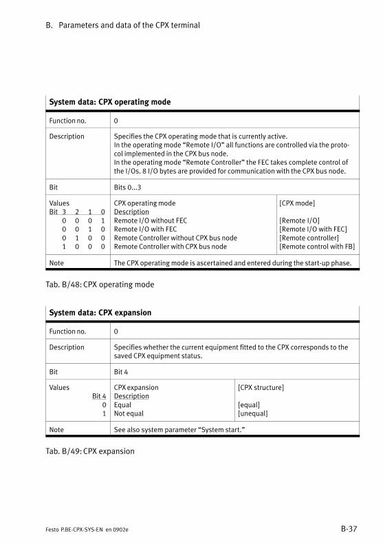
B. Parameters and data of the CPX terminal
B−37Festo P.BE−CPX−SYS−EN en 0902e
System data: CPX operating mode
Function no. 0
Description Specifies the CPX operating mode that is currently active.In the operating mode �Remote I/O" all functions are controlled via the proto�col implemented in the CPX bus node.In the operating mode �Remote Controller" the FEC takes complete control ofthe I/Os. 8 I/O bytes are provided for communication with the CPX bus node.
Bit Bits 0...3
ValuesBit 3 2 1 0
0 0 0 10 0 1 00 1 0 01 0 0 0
CPX operating modeDescriptionRemote I/O without FECRemote I/O with FECRemote Controller without CPX bus nodeRemote Controller with CPX bus node
[CPX mode]
[Remote I/O][Remote I/O with FEC][Remote controller][Remote control with FB]
Note The CPX operating mode is ascertained and entered during the start−up phase.
Tab.�B/48:CPX operating mode
System data: CPX expansion
Function no. 0
Description Specifies whether the current equipment fitted to the CPX corresponds to thesaved CPX equipment status.
Bit Bit 4
ValuesBit 4
01
CPX expansionDescriptionEqualNot equal
[CPX structure]
[equal][unequal]
Note See also system parameter �System start."
Tab.�B/49:CPX expansion

B. Parameters and data of the CPX terminal
B−38 Festo P.BE−CPX−SYS−EN en 0902e
System data: Handheld
Function no. 0
Description Specifies whether or not a handheld is connected.
Bit Bit 5
ValuesBit 5
01
HandheldDescriptionHandheld not connectedHandheld connected
[Handheld]
−[connection OK]
Note Information for the higher−order controllerIf necessary for test purposes, a parametrisation carried out by handheld is to becancelled by reloading the parameters, or forcing by higher−order PLC/IPC is tobe blocked whilst a handheld is connected.
Tab.�B/50:Handheld
System data: Force mode
Function no. 0
Description Specifies whether Force is blocked or enabled.
Bit Bit 6
ValuesBit 6
01
Force modeDescriptionDisabledEnabled
[Force mode]
[Disabled][Enabled]
Note See also system parameter �Force mode."
Tab.�B/51: Force mode

B. Parameters and data of the CPX terminal
B−39Festo P.BE−CPX−SYS−EN en 0902e
System data: System start
Function no. 0
Description Specifies how the system start of the CPX terminal is to be carried out
Bit Bit 7
ValuesBit 7
0
1
System startDescriptionSystem start with default parametrisation (factorysetting) and current CPX equipment statusSystem start with saved parametrisation and savedCPX equipment status
[System start]
[Default parameters]
[Saved parameters]
Note See also system parameter �System start."
Tab.�B/52: System start
System data: Fail safe
Function no. 1
Description Specifies whether Fail safe is active or inactive.
Bit Bits 0, 1
ValuesBit 1 0
0 00 11 1
Fail safeDescriptionReset all outputsHold last state (retain signal status)Assume fault mode
[Fail safe]
[Reset outputs][Hold last state][Assume fault mode]
Tab.�B/53: Fail safe
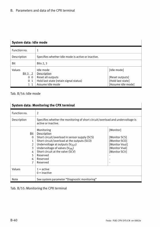
B. Parameters and data of the CPX terminal
B−40 Festo P.BE−CPX−SYS−EN en 0902e
System data: Idle mode
Function no. 1
Description Specifies whether Idle mode is active or inactive.
Bit Bits 2, 3
ValuesBit 3 2
0 00 11 1
Idle modeDescriptionReset all outputsHold last state (retain signal status)Assume Idle mode
[Idle mode]
[Reset outputs][Hold last state][Assume idle mode]
Tab.�B/54: Idle mode
System data: Monitoring the CPX terminal
Function no. 2
Description Specifies whether the monitoring of short circuit/overload and undervoltage isactive or inactive.
Bit01234567
MonitoringDescriptionShort circuit/overload in sensor supply (SCS)Short circuit/overload at the outputs (SCO)Undervoltage at outputs (VOUT)Undervoltage of valves (VVAL)Short circuit at the valve (SCV)ReservedReservedReserved
[Monitor]
[Monitor SCS][Monitor SCO][Monitor Vout][Monitor Vval][Monitor SCV]−−−
Values 1 = active0 = inactive
Note See system parameter �Diagnostic monitoring"
Tab.�B/55:Monitoring the CPX terminal
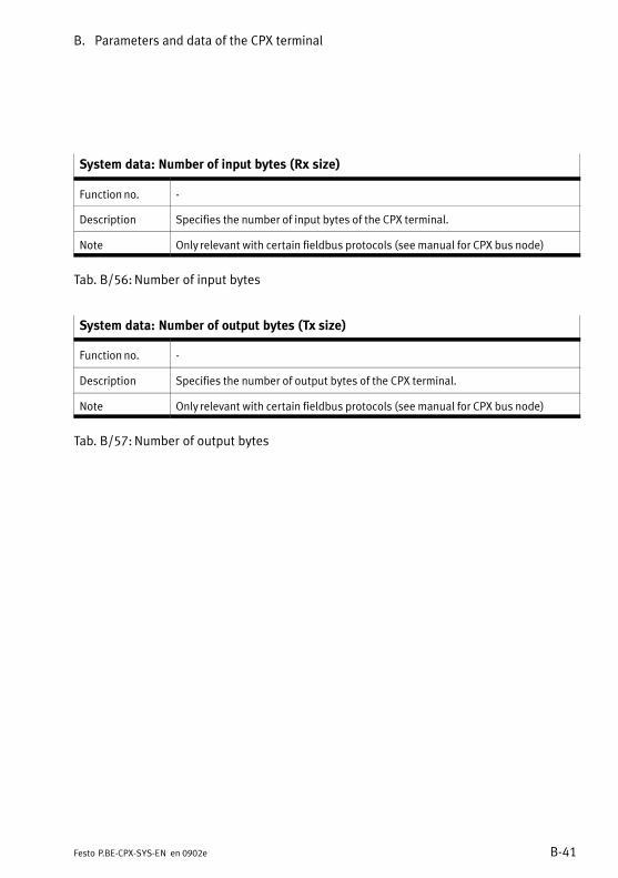
B. Parameters and data of the CPX terminal
B−41Festo P.BE−CPX−SYS−EN en 0902e
System data: Number of input bytes (Rx size)
Function no. −
Description Specifies the number of input bytes of the CPX terminal.
Note Only relevant with certain fieldbus protocols (see manual for CPX bus node)
Tab.�B/56:Number of input bytes
System data: Number of output bytes (Tx size)
Function no. −
Description Specifies the number of output bytes of the CPX terminal.
Note Only relevant with certain fieldbus protocols (see manual for CPX bus node)
Tab.�B/57:Number of output bytes

B. Parameters and data of the CPX terminal
B−42 Festo P.BE−CPX−SYS−EN en 0902e
B.2.9 Module data
The following module data is available for identifying modules:
Function no. Module data
16 + 16m + 0 Module code
16 + 16m + 13 Revision code
784 + m * 4 + 0784 + m * 4 + 1784 + m * 4 + 2784 + m * 4 + 3
Serial number
m = module number
Tab.�B/58:Overview of module data
Module data: Module code
Function no. 16 + 16m + 0; m = module number (0 ... 47)
Description Specifies the module code of the module.
Bit 0...7
Values Module code
0 : Reserved1 ... 63 : Digital modules64 ... 79 : Pneumatic interfaces80 ... 127 : Pneumatic modules128 ... 152: Analogue modules153 ... 196: Function or technology modules197 ... 201: Special modules202 ... 245: CPX bus node246 ... 255: Reserved
[Module code]
Note The module codes can be found in the relevant module descriptions.
Tab.�B/59:Module code

B. Parameters and data of the CPX terminal
B−43Festo P.BE−CPX−SYS−EN en 0902e
Module data: Revision code
Function no. 16 + 16m + 13; m = module number (0 ... 47)
Description Specifies the output status of the module.
Bit 0...7
Values Revision code
0...255
[Revision]
Note See type plate
Tab.�B/60: Revision code
Module data: Serial number
Function no. 784 + m * 4 + 0 (byte 0)784 + m * 4 + 1 (byte 1)784 + m * 4 + 2 (byte 2)784 + m * 4 + 3 (byte 3); m = module number (0 ... 47)
Description Specifies the series number of the module. In byte 0 one nibble (4 bits) containsthe year and the other nibble contains the month of the series (hexadecimalcoding). Of bytes 1..3 each nibble contains a figure of the series number (BCDcoded 1)).
1) BCD = binary coded decimal number (see Tab.�B/62 for an example)
Tab.�B/61: Serial number

B. Parameters and data of the CPX terminal
B−44 Festo P.BE−CPX−SYS−EN en 0902e
Function no. Bit number Example 1)
7 6 5 4 3 2 1 0 7 6 5 4 3 2 1 0
Nibble Nibble Nibble Nibble
784 + m * 4 + 0 Year 2) Month 3) 0 0 0 1 1 1 0 0
784 + m * 4 + 1 100.000 10.000 0 1 1 0 0 1 0 1
784 + m * 4 + 2 1 000 100 0 1 0 0 0 0 1 1
784 + m * 4 + 3 10 1 0 0 1 0 0 0 0 1
1) Example: Serial number 1C6543212) 0001 (1) = year 2001; 0010 (2) = year 2002 etc.3) 0001 (1) = January; 0010 (2) = February ... 1011 (B) = November; 1100 (C) = December
Tab.�B/62:Bit number

General information on parametrisation
C−1Festo P.BE−CPX−SYS−EN en 0902e
Appendix C
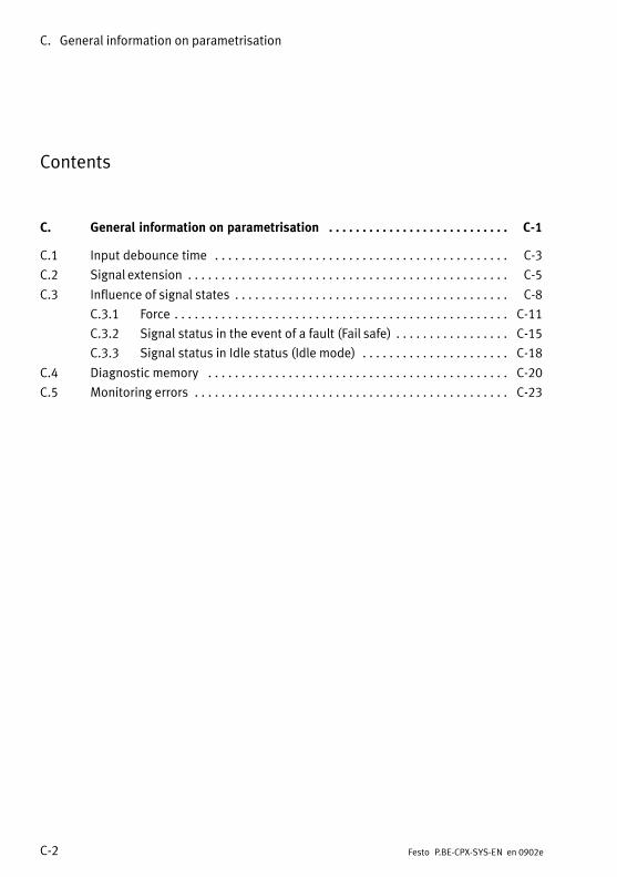
C. General information on parametrisation
C−2 Festo P.BE−CPX−SYS−EN en 0902e
Contents
C. General information on parametrisation C−1 . . . . . . . . . . . . . . . . . . . . . . . . . . .
C.1 Input debounce time C−3 . . . . . . . . . . . . . . . . . . . . . . . . . . . . . . . . . . . . . . . . . . . .
C.2 Signal extension C−5 . . . . . . . . . . . . . . . . . . . . . . . . . . . . . . . . . . . . . . . . . . . . . . . .
C.3 Influence of signal states C−8 . . . . . . . . . . . . . . . . . . . . . . . . . . . . . . . . . . . . . . . . .
C.3.1 Force C−11 . . . . . . . . . . . . . . . . . . . . . . . . . . . . . . . . . . . . . . . . . . . . . . . . . .
C.3.2 Signal status in the event of a fault (Fail safe) C−15 . . . . . . . . . . . . . . . . .
C.3.3 Signal status in Idle status (Idle mode) C−18 . . . . . . . . . . . . . . . . . . . . . .
C.4 Diagnostic memory C−20 . . . . . . . . . . . . . . . . . . . . . . . . . . . . . . . . . . . . . . . . . . . . .
C.5 Monitoring errors C−23 . . . . . . . . . . . . . . . . . . . . . . . . . . . . . . . . . . . . . . . . . . . . . . .

C. General information on parametrisation
C−3Festo P.BE−CPX−SYS−EN en 0902e
C.1 Input debounce time
Fundamentals
Input debounce times are specified in order to eliminate in�terfering changes of signal edge during switching procedures(bouncing of the input signal). For example, mechanicalswitches generate brief undesired signal edges during switch�ing procedures. The signal states which are thereby producedcan cause interference in the control sequence and shouldtherefore frequently be suppressed.
Interfering, undesired signal edges can be suppressed bya�PLC program in the higher−order controller. Interference cantherefore be avoided. With the CPX terminals, undesired sig�nal edges can be suppressed simply by parametrisation.
CPX parametrisation
With the CPX terminals, the input debounce time can be setwith an appropriate module parameter. The possible inputdebounce times therefore depend on the particular type ofmodule. Typical input debounce times are: 0.1�ms, 3 ms (typi�cal presetting), 10 ms and 20 ms.
Mode of operation
Changes of edge in the sensor signal will be accepted as alogical input signal (see Fig.�C/1) only when the specifieddebounce time has expired.

C. General information on parametrisation
C−4 Festo P.BE−CPX−SYS−EN en 0902e
Dependency diagram
End End1
2 2
3
4
0
1
0
1
Start = debounce time startedEnd = debounce time completely expired
Sensor signal is unstable (shorter than debounce time)Sensor signal is sufficiently stable (= debounce time)
Start Start Start Start Start Start
1 Start and end (sequence) of thedebounce time
2 Debounce time has expired
3 Sensor signal
4 Logical CPX signal
Fig.�C/1: Input debouncing

C. General information on parametrisation
C−5Festo P.BE−CPX−SYS−EN en 0902e
C.2 Signal extension
Fundamentals
Signal extension times are specified when very short signalsare to be taken into account in the control process. Shortsignals can occur, e.g. when an intermediate position is ex�ceeded and evaluation is necessary in order to produce atime−optimised consequent process before an end position isreached.
Depending on the type of sensor, the length of the signal,which is generated when the intermediate position is ex�ceeded, can fluctuate according to the positioning speed.There is a danger here that the short signals are not always�recognised" due to long cycle times of the higher−order controller.
With CPX terminals, a signal extension time can be defined byparametrisation of the appropriate input signal. Short signalswill then also be recognised reliably by the higher−order con�troller.
CPX parametrisation
With the CPX terminals, the signal extension time for the mo�dule is set with the appropriate module parameter. The poss�ible signal extension times depend on the type of module.Typical signal extension times are: 0.5�ms, 15 ms, 50 ms and100 ms.
The signal extension time for each channel can be activatedor deactivated with a further channel−orientated module para�meter. When preset, the signal extension time is inactive.

C. General information on parametrisation
C−6 Festo P.BE−CPX−SYS−EN en 0902e
Mode of operation
Signal states accepted as logical input signals usually remainvalid at least until the specified minimum signal duration hasexpired. Change of edge within the minimum signal durationare ignored (see Fig.�C/2). Fixed debounce times remain ef�fective.
Case 1: Change of edge within the signal extensiontime
The logical CPX signal is supplied when the signal extensiontime and, if applicable, the debounce time has expired.
1 Sensor signal
2 Logical CPXsignal
3 Change of edgewithin the signalextension time
0
1
0
1
0
1
0
1
a) Rising edge
Expiration of the debounce time
Expiration of the signal extension time
b) Falling edge
1
2
1
2
3
3
Fig.�C/2: Change of edge within the signal extension time
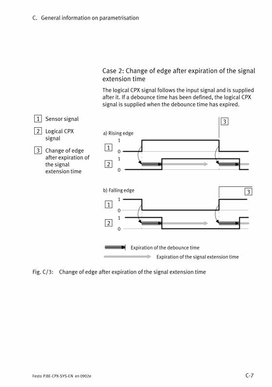
C. General information on parametrisation
C−7Festo P.BE−CPX−SYS−EN en 0902e
Case 2: Change of edge after expiration of the signalextension time
The logical CPX signal follows the input signal and is suppliedafter it. If a debounce time has been defined, the logical CPXsignal is supplied when the debounce time has expired.
1 Sensor signal
2 Logical CPXsignal
3 Change of edgeafter expiration ofthe signalextension time
0
1
0
1
a) Rising edge
Expiration of the debounce time
Expiration of the signal extension time
b) Falling edge
1
2
1
2
0
1
0
1
3
3
Fig.�C/3: Change of edge after expiration of the signal extension time

C. General information on parametrisation
C−8 Festo P.BE−CPX−SYS−EN en 0902e
C.3 Influence of signal states
You can influence the signal states of the CPX terminalthrough the following functions:
Function Priority Brief description Signals able tobe influenced
Forcing 2) 1 Influences signal states independently of actual signal states (see also section C.3.1)
I/O signals
Fail safe 2 Determines signal states that become effective withfieldbus communication faults (see also sectionC.3.2)
A signals
Idle mode 1) 3 Determines signal states that become effectivewhen changing into the Idle status (see also sectionC.3.3)
A signals
1) Only relevant for certain fieldbus protocols2) Mainly used for test purposes in the commissioning phase.
Tab.�C/1: Functions for influencing signal states
If several functions are active at the same time, the followingapplies:
� Force signals have the highest priority
� Fail−safe signals have precedence over Idle mode signals.
Overview on the Force, Fail safe and Idle mode func�tions
Influencing output signals
With system parameters, you enter the fundamental settingsfor the respective function. With appropriate setting of thesystem parameter, you can determine, through channel−specific module parameters, the desired signal state for eachchannel individually. The following diagrams give an overviewof this:

C. General information on parametrisation
C−9Festo P.BE−CPX−SYS−EN en 0902e
Force
Fail�safe
Idle�mode
Idle�mode�channel�X
Reset�outputs
01
0
Idle�mode
Assume�idle�mode Hold�last�state
Memory�card
Fail�safe�channel�X
Reset�outputs
01
0
Fail�safe
Assume�fault�mode Hold�last�state
0 1
Force�channel�X
Force�mode
enable disable
1
disable
Idle mode is onlyrelevant forcertain fieldbusprotocols
Output signal (e.g. over fieldbus)
Memory card
System parameters
Module parameters
Module parameters
Module parameters
System parameters
System parameters
Output
Yes No
Yes No
Fieldbus communication fault
Idle mode status
1 Status LED of the respective output
Fig.�C/4: Influencing output signals

C. General information on parametrisation
C−10 Festo P.BE−CPX−SYS−EN en 0902e
Influencing input signals
1Force 0 1
Force�channel�X
Force�mode
enable disable
disable
Input
Input signal
System parameters
Module parameters
1 Status LED of the respective input
Fig.�C/5: Influencing input signals
Forcing an input does not modify the input signal itself andcannot be observed at the relevant status LED. The logicalstatus of the input only changes internally and may be effec�tive programme technically.
Obtain further information on Idle mode, Fail safe and Forcingfrom the following sections.

C. General information on parametrisation
C−11Festo P.BE−CPX−SYS−EN en 0902e
C.3.1 Force
Fundamentals
The function Force permits the manipulation of signal statesindependent of actual operating conditions. Force enablesinput and output signals to be overwritten, Input signalsactually present or changes of status by program will be ig�nored. The input signals actually present and the output sig�nals generated by the user program only become valid againwhen the function Force is deactivated.
WarningDepending on the functions of the machine/system, themanipulation of signal states can lead to serious personalinjury or material damage.
Use the Force function very carefully, in order to avoid damage.
The �Force" function is used mainly in the commissioningphase in order to set certain signals to the desired status fortest purposes even if the wiring is not complete.
CPX parametrisation
With CPX terminals, Force parametrisation can be used for:
� Digital inputs
� Digital outputs
� Valves
� I/Os of the I/O diagnostic interface and status bits
� Analogue inputs
� Analogue outputs

C. General information on parametrisation
C−12 Festo P.BE−CPX−SYS−EN en 0902e
By means of a system parameter, Force is enabled globally forthe CPX terminal or blocked.
System parameters Settings Description
Force mode Disabled(presetting)
Force is blocked for the complete CPX terminal
Enabled Force is enabled for the complete CPX terminal
Tab.�C/2: System parameter Force mode
The signal status can be determined channel−orientated (out�put/valve/input) for each module (see Tab.�C/3).
Module parameters Settings Description
Force mode Disabled(presetting)
Force is blocked for the channel
Force state Accept the signal status defined by Force state
Force state� Digital signal
Reset signal (preset�ting)
Reset input/output signal
Set signal Set input/output signal
� Analogue signal Analogue value(0 = presetting)
Value of the analogue signal
Tab.�C/3: Module parameters �Force mode" and �Force state"
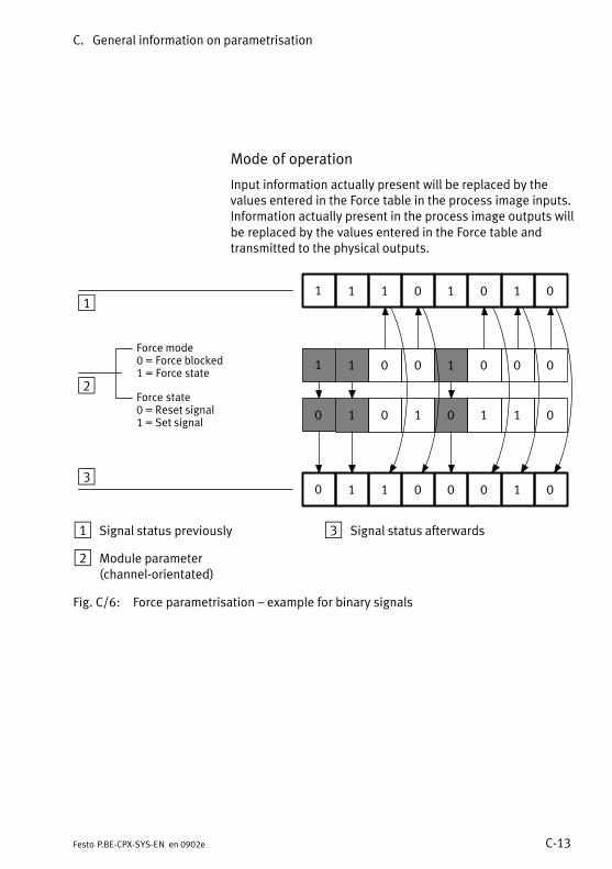
C. General information on parametrisation
C−13Festo P.BE−CPX−SYS−EN en 0902e
Mode of operation
Input information actually present will be replaced by thevalues entered in the Force table in the process image inputs.Information actually present in the process image outputs willbe replaced by the values entered in the Force table andtransmitted to the physical outputs.
1 1 0 0 1 0 0 0
0 1 0 1 0 1 1 0
1 1 1 0 1 0 1 0
Force mode0 = Force blocked1 = Force state
Force state0 = Reset signal1 = Set signal
0 1 1 0 0 0 1 0
1
2
3
1 Signal status previously
2 Module parameter(channel−orientated)
3 Signal status afterwards
Fig.�C/6: Force parametrisation � example for binary signals

C. General information on parametrisation
C−14 Festo P.BE−CPX−SYS−EN en 0902e
1 1 0 0 1 0 0 0
100 505 100 321 202 110 80 50
321 288 333 432 400 505 11 500
Force mode0 = Force blocked1 = Force state
Force state
100 505 333 432 202 505 11 500
1
2
3
1 Analogue signal previously
2 Module parameter(channel−orientated)
3 Analogue signal afterwards
Fig.�C/7: Force parametrisation � example for analogue signals

C. General information on parametrisation
C−15Festo P.BE−CPX−SYS−EN en 0902e
C.3.2 Signal status in the event of a fault (Fail safe)
Fundamentals
With the aid of the so−called fail−safe parametrisation, thesignal status which the outputs are to assume in the event offieldbus communication faults, can be determined (fail−safestatus). In this way, a defined machine/system status shouldbe created in the event of fieldbus communication faults (e.g.failure of the higher−order PLC/IPC).
WarningDepending on the functions of the machine/system, themanipulation of signal states can lead to serious personalinjury or material damage.
Use the Fail−safe parametrisation very carefully, in order toavoid damage.
CPX parametrisation
With CPX terminals, fail−safe parametrisation can be used for:
� Digital outputs
� Analogue outputs
� Valves
By means of the system parameter fail−safe, you can globallydetermine the signal status which the outputs/valves are toassume in the event of fieldbus communication faults, e.g. inthe event of:
� Communication failure (fieldbus interruption, PLC failure)
� Communication stop

C. General information on parametrisation
C−16 Festo P.BE−CPX−SYS−EN en 0902e
System parameters Settings Description
Fail safe Reset outputs(presetting)
Reset all outputs/valves
Hold last state Retain current signal status for all outputs/valves
Assume Fault mode value
Accept the signal status defined for the relevantchannel
Tab.�C/4: System parameter �Fail safe"
If �Accept fault mode value" is activated, the signal statesdefined by module parameter for the relevant channel willbecome effective (see Fig.�C/8).
Module parameters Settings Description
Fault mode Hold last state Retain current signal status
Fault state(presetting)
Accept the signal status defined by Fault state
Fault state� Digital signal
Reset output(presetting)
Reset output signal (output/valve)
Set output Set output signal (output/valve)
� Analogue signal Analogue value Value of the analogue signal
Tab.�C/5: Module parameters Fault mode and Fault state
Mode of operation
The �Fault mode" parameter is used to determine whetherthe current signal status is to be retained or whether the signal status defined by �Fault state" is to be accepted.

C. General information on parametrisation
C−17Festo P.BE−CPX−SYS−EN en 0902e
0 1 0 1 1 1 0 0
0 0 0 1 0 1 0 0
1 1 0 0 1 1 1 0
Fault mode0 = Hold last state1 = Fault state
Fault state0 = Reset output1 = Set output
1 0 0 1 0 1 1 0
1
2
3
1 Signal status before the fault
2 Module parameter(channel−orientated)
3 Signal status after the fault
Fig.�C/8: Fail−safe parametrisation � example for binary signals
0 1 0 1 1 1 0 0
222 500 500 500 333 321 100 200
100 321 444 230 700 604 0 333
Fault mode0 = Hold last state1 = Fault state
Fault state
100 500 444 500 333 321 0 333
1
2
3
1 Signal status before the fault
2 Module parameter(channel−orientated)
3 Signal status after the fault
Fig.�C/9: Fail−safe parametrisation � example for analogue signals

C. General information on parametrisation
C−18 Festo P.BE−CPX−SYS−EN en 0902e
C.3.3 Signal status in Idle status (Idle mode)
This function is only relevant with certain fieldbus protocols(see manual for CPX bus node).
Fundamentals
Idle mode parametrisation helps determine which signalstatus outputs/valves should take when changing into theIdle status. In this way a defined machine/system statusshould be created.
WarningDepending on the functions of the machine/system, themanipulation of signal states can lead to serious personalinjury or material damage.
Use the Idle mode parametrisation very carefully, in orderto avoid damage.
CPX parametrisation
With CPX terminals, Idle mode parametrisation can be usedfor:
� Digital outputs
� Analogue outputs
� Valves
By means of the system parameter Idle mode, you can glo�bally determine the signal status which the outputs/valvesare to assume when changing into the Idle status.

C. General information on parametrisation
C−19Festo P.BE−CPX−SYS−EN en 0902e
System parameters Settings Description
System Idle mode Reset outputs(presetting)
Reset all outputs/valves
Hold last state Retain current signal status for all outputs/valves
Assume Idle mode value
Accept the signal status defined for the relevantchannel
Tab.�C/6: System parameter System Idle mode
If �Accept fault mode value" is activated, the signal statesdefined by module parameter for the relevant channel willbecome effective (see Tab.�C/7).
Module parameters Settings Description
Idle mode Hold last state Retain current signal status
Idle state(presetting)
Accept the signal status defined by the Idle state
Idle state� Digital signal
Reset output(presetting)
Reset output signal (output/valve)
Set output Set output signal (output/valve)
� Analogue signal Analogue value Value of the analogue signal
Tab.�C/7: Module parameters �Idle mode" and �Idle state"
Mode of operation
Functionally identical to Fail−safe parametrisation (see alsoFig.�C/8 and Fig.�C/9).

C. General information on parametrisation
C−20 Festo P.BE−CPX−SYS−EN en 0902e
C.4 Diagnostic memory
Fundamentals
A diagnostic memory serves for protocolling fault states. Ifthe time when faults occur and if fault sequences are regis�tered, this will facilitate the search for the cause of the faultswhich are otherwise difficult to locate. If the causes are elim�inated, faults can be avoided over long periods.
CPX parametrisation
Various diagnostic memory filters can be parameterised bymeans of diagnostic memory parameters (see section B.2.4).With these filters the registering of certain system states canbe suppressed, and both starting and stopping can be con�trolled. The method of operation of the diagnostic memoryfilters is shown in Fig.�C/10.

C. General information on parametrisation
C−21Festo P.BE−CPX−SYS−EN en 0902e
Fault end filter
Start: Error
Run/stopFilter 2
Error number filter
Module/channel filter
0 = Always register
1 = Register up to the defined error number
2 = Register up to the defined error number + module number
3 = Register up to the defined error number + module number + 3 = channel number
4 = Register as from the defined error number
5 = Register as from the defined error number + module number
6 = Register as from the defined error number + module number + 6 = channel number
Run/stop filter 1 The first 40 faults or the last 40 faults
Register end of fault or not
Register defined error number or not
Register only error number of a module/channel
Diagn
ostic
mem
ory
MN = module number, CN = channel number, FN = error number
Fig.�C/10: The method of operation of the diagnostic memory filters

C. General information on parametrisation
C−22 Festo P.BE−CPX−SYS−EN en 0902e
Mode of operation
With the CPX terminals the start and end of a fault can beprotocolled in the internal diagnostic memory. The diagnosticmemory contains up to 40�entries. In addition to informationon localising the fault, the relevant time point is saved,measured from the moment the power supply is switched on.A diagnostic entry consists of 10�bytes. The first five bytescontain information on the time point. The last five bytes con�tain information on the fault (see section B.2.5).
With the aid of the function number, entries in the diagnosticmemory can be read out via the I/O diagnostic interface irre�spective of the fieldbus protocol used. The various fieldbusprotocols provide, where applicable, further possibilities forreading out and configuring the CPX diagnostic memory (seethe manual for the specific CPX bus node).

C. General information on parametrisation
C−23Festo P.BE−CPX−SYS−EN en 0902e
C.5 Monitoring errors
Fundamentals
Monitoring functions that run automatically can be activatedand deactivated by parametrisation.
The activation of monitoring functions helps to guarantee thefunctionality of the machine/system and to avoid unnecess�ary idle periods. The deactivation of monitoring functionshelps to avoid disturbing error messages, e.g.:
� During commissioning
� During an EMERGENCY STOP, if the EMERGENCY STOPconcept of the machine/system requires that the loadvoltage for the valves and output modules be switchedoff. The error messages (e.g undervoltage), which aretriggered when the load voltage is switched off, should be frequently suppressed here.
CPX parametrisation
The CPX terminal permits the monitoring of various types offault (e.g. short circuit, wire fracture, undervoltage, etc.). Thedifferent monitoring functions can be activated or deactivatedglobally by system parameters for the complete CPX terminaland by module parameters for a single CPX module or anindividual channel. Activation of a monitoring function causesthe following:

C. General information on parametrisation
C−24 Festo P.BE−CPX−SYS−EN en 0902e
Monitoring Reaction to activation
Module parametersMonitoring
A fault on the module will be:� Forwarded to the CPX bus node� Displayed by the module common error LED
System parametersMonitoring
A fault registered by the module will be:� Sent to the higher−order fieldbus master� Displayed by the red SF−LED on the CFX bus node� Entered in the module diagnostic data and, if applicable, in the
status bits� Entered, if applicable, in the diagnostic memory
Tab.�C/8: Monitoring
The behaviour of the channel fault LED is normally controlledby hardware functions and does not therefore depend on thesetting of the monitoring functions.
The following monitoring functions can be activated or deacti�vated globally:
System parameter monitoring Description
Undervoltage of valves Monitors the load voltage supply for the valves
Undervoltage of outputs Monitors the load voltage supply for the outputs
Short circuit/overload of outputs Monitors whether outputs are overloaded or short circui�ted
Short circuit/overload, sensor supply Monitors whether sensor supply is overloaded or shortcircuited
Tab.�C/9: System parameter monitoring

C. General information on parametrisation
C−25Festo P.BE−CPX−SYS−EN en 0902e
The following monitoring functions can be activated or deactivated by modules, providing the module supports the relevant monitoring function:
Module parameter monitoring Description
Short circuit/overload, sensor supply Monitors whether sensor supply is overloaded or shortcircuited
Short circuit/overload of outputs Monitors whether outputs are overloaded or short circuited
Undervoltage for outputs/valves Monitors the load voltage supply for the valves/outputs
Short circuit/overload at the valve Monitors whether valve outputs are overloaded or shortcircuited
Upper/lower limit value Monitors the upper/lower limit
Parametrisation error Monitors module parametrisation (plausibility check)
Monitoring wire fracture (channel−specific)
Monitoring can be activated and deactivated for eachchannel (0 = inactive; 1 = active).
Tab.�C/10: Module parameter monitoring
The meaning of the module parameter depends on the mo�dule used. Detailed information can be found in the manualfor the relevant module.

C. General information on parametrisation
C−26 Festo P.BE−CPX−SYS−EN en 0902e

Index
D−1Festo P.BE−CPX−SYS−EN en 0902e
Appendix D

D. Index
D−2 Festo P.BE−CPX−SYS−EN en 0902e
Contents
D. Index D−1 . . . . . . . . . . . . . . . . . . . . . . . . . . . . . . . . . . . . . . . . . . . . . . . . . . . . . . . . .

D. Index
D−3Festo P.BE−CPX−SYS−EN en 0902e
A
Abbreviations XV . . . . . . . . . . . . . . . . . . . . . . . . . . . . . . . . . . .
Additional power supplyfor electric outputs 3−13 . . . . . . . . . . . . . . . . . . . . . . . . . . . . for valves 3−14 . . . . . . . . . . . . . . . . . . . . . . . . . . . . . . . . . . . .
Assembly 2−3 . . . . . . . . . . . . . . . . . . . . . . . . . . . . . . . . . . . . . . CPX terminal 2−21 . . . . . . . . . . . . . . . . . . . . . . . . . . . . . . . . . CPX terminal on the wall 2−29 . . . . . . . . . . . . . . . . . . . . . . . general instructions 2−3 . . . . . . . . . . . . . . . . . . . . . . . . . . . . H−rail 2−21 . . . . . . . . . . . . . . . . . . . . . . . . . . . . . . . . . . . . . . . metal interlinking blocks 2−17 . . . . . . . . . . . . . . . . . . . . . . . right−hand end plate (Midi/Maxi) 2−15 . . . . . . . . . . . . . . . .
B
Behaviour after short circuit B−17 . . . . . . . . . . . . . . . . . . . . . .
C
CableOperating voltage cable A−7 . . . . . . . . . . . . . . . . . . . . . . . . . Pre−assembling the connecting cable 3−4 . . . . . . . . . . . . . . Selecting the field bus cable 3−3 . . . . . . . . . . . . . . . . . . . . . Selecting the operating voltage cable 3−3 . . . . . . . . . . . . . .
Cable length and cross−sectional area A−7 . . . . . . . . . . . . . . .
Calculating the current consumption 3−9 . . . . . . . . . . . . . . . .
CE marking VIII . . . . . . . . . . . . . . . . . . . . . . . . . . . . . . . . . . . . .
Certification VIII . . . . . . . . . . . . . . . . . . . . . . . . . . . . . . . . . . . .
Certifications, Underwriters Laboratories Inc. (UL) VIII . . . . .
Commissioning 4−3 . . . . . . . . . . . . . . . . . . . . . . . . . . . . . . . . . .
Common error LED on CPX I/O modules 5−9 . . . . . . . . . . . . .
Connection block 1−17 . . . . . . . . . . . . . . . . . . . . . . . . . . . . . . .
Conventions XII . . . . . . . . . . . . . . . . . . . . . . . . . . . . . . . . . . . . .
CPA, valve terminal pneumatics 1−16 . . . . . . . . . . . . . . . . . . .

D. Index
D−4 Festo P.BE−CPX−SYS−EN en 0902e
CPX bus node 1−8 . . . . . . . . . . . . . . . . . . . . . . . . . . . . . . . . . . .
CPX Front End Controller 1−8 . . . . . . . . . . . . . . . . . . . . . . . . . .
CPX I/O modules 1−9 . . . . . . . . . . . . . . . . . . . . . . . . . . . . . . . .
CPX terminalrules for assembly 2−4 . . . . . . . . . . . . . . . . . . . . . . . . . . . . . start−up behaviour 4−10 . . . . . . . . . . . . . . . . . . . . . . . . . . . . with valve terminal pneumatics of type CPA 1−16 . . . . . . . . with valve terminal pneumatics of type Midi/Maxi 1−15 . . with valve terminal pneumatics of type MPA 1−13 . . . . . . . with valve terminal pneumatics of type VTSA 1−14 . . . . . . without pneumatics 1−12 . . . . . . . . . . . . . . . . . . . . . . . . . . .
CPX−CP interface 1−10 . . . . . . . . . . . . . . . . . . . . . . . . . . . . . . .
CurrentCalculating the current consumption 3−9 . . . . . . . . . . . . . . external fuse protection 3−18 . . . . . . . . . . . . . . . . . . . . . . . .
D
Datadata saved in the CPX terminal B−3 . . . . . . . . . . . . . . . . . . . Technical data A−3 . . . . . . . . . . . . . . . . . . . . . . . . . . . . . . . . .
Data formatAnalogue value of inputs B−19 . . . . . . . . . . . . . . . . . . . . . . . Analogue value of outputs B−20 . . . . . . . . . . . . . . . . . . . . . .
DescriptionElectronics XIII . . . . . . . . . . . . . . . . . . . . . . . . . . . . . . . . . . . Pneumatics XIV . . . . . . . . . . . . . . . . . . . . . . . . . . . . . . . . . . .
Diagnostic memoryFilter C−20 . . . . . . . . . . . . . . . . . . . . . . . . . . . . . . . . . . . . . . . Filters 4−8 . . . . . . . . . . . . . . . . . . . . . . . . . . . . . . . . . . . . . . . Fundamentals C−20 . . . . . . . . . . . . . . . . . . . . . . . . . . . . . . . .
Diagnostic memory data 1−25 , B−29 . . . . . . . . . . . . . . . . . . . . Number of entries in the diagnostic memory B−29 . . . . . . . Overflow B−30 . . . . . . . . . . . . . . . . . . . . . . . . . . . . . . . . . . . . Status B−30 . . . . . . . . . . . . . . . . . . . . . . . . . . . . . . . . . . . . . .
Diagnostic memory parameters 4−8 , B−23 , B−24 . . . . . . . . . Channel number (CN) B−28 . . . . . . . . . . . . . . . . . . . . . . . . . . Entries remanent with power ON B−24 . . . . . . . . . . . . . . . . .

D. Index
D−5Festo P.BE−CPX−SYS−EN en 0902e
Error number filter B−26 . . . . . . . . . . . . . . . . . . . . . . . . . . . . Fault end filter B−26 . . . . . . . . . . . . . . . . . . . . . . . . . . . . . . . . Fault number (FN) B−28 . . . . . . . . . . . . . . . . . . . . . . . . . . . . . Module number (MN) B−27 . . . . . . . . . . . . . . . . . . . . . . . . . . Module/channel filter B−27 . . . . . . . . . . . . . . . . . . . . . . . . . Run/stop filter 1 B−24 . . . . . . . . . . . . . . . . . . . . . . . . . . . . . . Run/stop filter 2 B−25 . . . . . . . . . . . . . . . . . . . . . . . . . . . . . .
Diagnosticsfunctions 1−25 . . . . . . . . . . . . . . . . . . . . . . . . . . . . . . . . . . . . Possibilities 5−4 . . . . . . . . . . . . . . . . . . . . . . . . . . . . . . . . . . .
Dismantling 2−3 . . . . . . . . . . . . . . . . . . . . . . . . . . . . . . . . . . . .
E
Earthingcomponents 2−15 . . . . . . . . . . . . . . . . . . . . . . . . . . . . . . . . . Potential equalisation 3−20 . . . . . . . . . . . . . . . . . . . . . . . . .
Electronics module 1−18 . . . . . . . . . . . . . . . . . . . . . . . . . . . . . .
EMERGENCY STOP concept 3−12 . . . . . . . . . . . . . . . . . . . . . . .
End plates 2−15 , 2−16 . . . . . . . . . . . . . . . . . . . . . . . . . . . . . . . .
ErrorLocation of error 5−12 . . . . . . . . . . . . . . . . . . . . . . . . . . . . . . Type of error 5−12 . . . . . . . . . . . . . . . . . . . . . . . . . . . . . . . . .
Error control C−23 . . . . . . . . . . . . . . . . . . . . . . . . . . . . . . . . . . .
Error numbers 5−19 . . . . . . . . . . . . . . . . . . . . . . . . . . . . . . . . . Example 5−18 . . . . . . . . . . . . . . . . . . . . . . . . . . . . . . . . . . . . System diagnostic data B−33 . . . . . . . . . . . . . . . . . . . . . . . .
Event of fault C−15 . . . . . . . . . . . . . . . . . . . . . . . . . . . . . . . . . .
F
Fail safe B−10 , C−8 , C−15 . . . . . . . . . . . . . . . . . . . . . . . . . . . . .
Fail−safe parametrisation 4−7 , B−21 , C−15 . . . . . . . . . . . . . . . Examples C−17 . . . . . . . . . . . . . . . . . . . . . . . . . . . . . . . . . . . .
Fault mode C−16 . . . . . . . . . . . . . . . . . . . . . . . . . . . . . . . . . . . .
Fault state C−16 . . . . . . . . . . . . . . . . . . . . . . . . . . . . . . . . . . . . .

D. Index
D−6 Festo P.BE−CPX−SYS−EN en 0902e
Fieldbus, interruptions 4−10 . . . . . . . . . . . . . . . . . . . . . . . . . .
Force B−22 , C−8 , C−11 . . . . . . . . . . . . . . . . . . . . . . . . . . . . . . .
Force mode B−11 . . . . . . . . . . . . . . . . . . . . . . . . . . . . . . . . . . . .
Forwarding function 3−14 . . . . . . . . . . . . . . . . . . . . . . . . . . . . .
Functional earthing 3−20 . . . . . . . . . . . . . . . . . . . . . . . . . . . . .
Fuse 3−18 , A−4 . . . . . . . . . . . . . . . . . . . . . . . . . . . . . . . . . . . . .
Fuses 3−10 . . . . . . . . . . . . . . . . . . . . . . . . . . . . . . . . . . . . . . . . .
H
H−rail mounting 2−21 . . . . . . . . . . . . . . . . . . . . . . . . . . . . . . . .
I
I/O diagnostic interface 1−25 , 5−11 , 5−14 . . . . . . . . . . . . . . . .
Idle mode 4−7 , B−12 , B−22 , C−8 . . . . . . . . . . . . . . . . . . . . . . . Parametrisation B−22 , C−18 . . . . . . . . . . . . . . . . . . . . . . . . . Signal status C−18 . . . . . . . . . . . . . . . . . . . . . . . . . . . . . . . . .
Information, Additional XIII . . . . . . . . . . . . . . . . . . . . . . . . . . .
Input debounce time B−18 , C−3 . . . . . . . . . . . . . . . . . . . . . . . .
Input modules, Short circuit/overload 5−10 . . . . . . . . . . . . . .
Installation, general instructions 3−3 . . . . . . . . . . . . . . . . . . . .
Intended use VII . . . . . . . . . . . . . . . . . . . . . . . . . . . . . . . . . . .
Interlinking block 1−18 . . . . . . . . . . . . . . . . . . . . . . . . . . . . . . . assembly with metal interlinking blocks 2−17 . . . . . . . . . . . Overview 1−19 . . . . . . . . . . . . . . . . . . . . . . . . . . . . . . . . . . . . Pin allocation 3−19 . . . . . . . . . . . . . . . . . . . . . . . . . . . . . . . . with additional power supply for outputs 3−13 . . . . . . . . . . with additional power supply for valves 3−14 . . . . . . . . . . . with push−pull forwarding function 3−14 . . . . . . . . . . . . . . . with supply (push−pull) 1−22 . . . . . . . . . . . . . . . . . . . . . . . . with system supply 3−13 . . . . . . . . . . . . . . . . . . . . . . . . . . . without supply 3−15 . . . . . . . . . . . . . . . . . . . . . . . . . . . . . . .
Interruption, fieldbus 4−10 . . . . . . . . . . . . . . . . . . . . . . . . . . . .
L
LEDsDiagnostics on CPX I/O modules 5−9 . . . . . . . . . . . . . . . . . .

D. Index
D−7Festo P.BE−CPX−SYS−EN en 0902e
Diagnostics on the CPX bus node 5−5 . . . . . . . . . . . . . . . . . Module common error LED 5−9 . . . . . . . . . . . . . . . . . . . . . .
M
Midi/Maxi, valve terminal pneumatics 1−15 . . . . . . . . . . . . . .
Module code B−42 . . . . . . . . . . . . . . . . . . . . . . . . . . . . . . . . . . .
Module common error LED 5−9 . . . . . . . . . . . . . . . . . . . . . . . .
Module data B−42 . . . . . . . . . . . . . . . . . . . . . . . . . . . . . . . . . . . Module code B−42 . . . . . . . . . . . . . . . . . . . . . . . . . . . . . . . . . Revision code B−43 . . . . . . . . . . . . . . . . . . . . . . . . . . . . . . . . Serial number B−43 . . . . . . . . . . . . . . . . . . . . . . . . . . . . . . . .
Module diagnostic data B−34 . . . . . . . . . . . . . . . . . . . . . . . . . Module error number B−35 . . . . . . . . . . . . . . . . . . . . . . . . . . Number of the first faulty channel B−35 . . . . . . . . . . . . . . . .
Module parameters 4−7 , B−15 . . . . . . . . . . . . . . . . . . . . . . . . . Behaviour after short circuit B−17 . . . . . . . . . . . . . . . . . . . . Channel−specific module parameter B−20 , B−21 , B−22 . . . Data format for analogue value of inputs B−19 . . . . . . . . . . Data format for analogue value of outputs B−20 . . . . . . . . . Fault mode C−16 . . . . . . . . . . . . . . . . . . . . . . . . . . . . . . . . . . Fault state C−16 . . . . . . . . . . . . . . . . . . . . . . . . . . . . . . . . . . . Force mode C−12 . . . . . . . . . . . . . . . . . . . . . . . . . . . . . . . . . . Force state C−12 . . . . . . . . . . . . . . . . . . . . . . . . . . . . . . . . . . Idle mode C−19 . . . . . . . . . . . . . . . . . . . . . . . . . . . . . . . . . . . Idle state C−19 . . . . . . . . . . . . . . . . . . . . . . . . . . . . . . . . . . . . Input debounce time B−18 . . . . . . . . . . . . . . . . . . . . . . . . . . Monitoring C−24 . . . . . . . . . . . . . . . . . . . . . . . . . . . . . . . . . . Monitoring of wire break C−25 . . . . . . . . . . . . . . . . . . . . . . . Monitoring the CPX module B−16 . . . . . . . . . . . . . . . . . . . . . Signal extension time B−19 . . . . . . . . . . . . . . . . . . . . . . . . . .
Moduleselectric, structure 1−17 . . . . . . . . . . . . . . . . . . . . . . . . . . . . . electrical, overview 1−4 . . . . . . . . . . . . . . . . . . . . . . . . . . . . .
MonitoringCPX module B−16 . . . . . . . . . . . . . . . . . . . . . . . . . . . . . . . . . Errors C−23 . . . . . . . . . . . . . . . . . . . . . . . . . . . . . . . . . . . . . . . Module parameters C−25 . . . . . . . . . . . . . . . . . . . . . . . . . . . System parameters C−24 . . . . . . . . . . . . . . . . . . . . . . . . . . .

D. Index
D−8 Festo P.BE−CPX−SYS−EN en 0902e
Wire break B−21 . . . . . . . . . . . . . . . . . . . . . . . . . . . . . . . . . .
Mounting, additional, for wall mounting 2−32 . . . . . . . . . . . .
MPA, valve terminal pneumatics 1−13 . . . . . . . . . . . . . . . . . . .
N
Notes on the use of this manual XII . . . . . . . . . . . . . . . . . . . . .
O
Operating voltageExample of connection 3−20 , 3−22 . . . . . . . . . . . . . . . . . . . . Operating voltage cable A−7 . . . . . . . . . . . . . . . . . . . . . . . . .
Overload B−9 . . . . . . . . . . . . . . . . . . . . . . . . . . . . . . . . . . . . . . .
P
Parameters B−3 . . . . . . . . . . . . . . . . . . . . . . . . . . . . . . . . . . . .
Pictograms XI . . . . . . . . . . . . . . . . . . . . . . . . . . . . . . . . . . . . . .
Pin allocation of the interlinking blocks 3−19 . . . . . . . . . . . . .
Pneumatic interface 1−10 . . . . . . . . . . . . . . . . . . . . . . . . . . . . .
Potential equalisation 3−20 . . . . . . . . . . . . . . . . . . . . . . . . . . .
Power supply 1−19 , 3−12 . . . . . . . . . . . . . . . . . . . . . . . . . . . . . Tolerance range 3−12 . . . . . . . . . . . . . . . . . . . . . . . . . . . . . .
Power supply unit, Selecting the power supply unit 3−8 . . . .
Pre−assembling 3−5 . . . . . . . . . . . . . . . . . . . . . . . . . . . . . . . . .
Push pullforwarding function 3−14 . . . . . . . . . . . . . . . . . . . . . . . . . . . Overview of supply types 1−22 . . . . . . . . . . . . . . . . . . . . . .
R
Range of application VIII . . . . . . . . . . . . . . . . . . . . . . . . . . . . .
Revision code B−43 . . . . . . . . . . . . . . . . . . . . . . . . . . . . . . . . . .

D. Index
D−9Festo P.BE−CPX−SYS−EN en 0902e
Rules for assembly 2−4 . . . . . . . . . . . . . . . . . . . . . . . . . . . . . . .
S
Serial number B−43 . . . . . . . . . . . . . . . . . . . . . . . . . . . . . . . . . .
Service IX . . . . . . . . . . . . . . . . . . . . . . . . . . . . . . . . . . . . . . . . .
Settings on the CPX bus node 3−6 . . . . . . . . . . . . . . . . . . . . . .
Short circuit/overload 5−10 . . . . . . . . . . . . . . . . . . . . . . . . . . . Monitoring B−9 . . . . . . . . . . . . . . . . . . . . . . . . . . . . . . . . . . .
Signal extension time B−19 , B−20 , C−5 . . . . . . . . . . . . . . . . . .
Start−up behaviour of the CPX terminal 4−10 . . . . . . . . . . . . .
Status bits 1−25 , 5−11 . . . . . . . . . . . . . . . . . . . . . . . . . . . . . . .
Structure of the diagnostic memory B−30 . . . . . . . . . . . . . . . .
Supply, power supply 1−19 . . . . . . . . . . . . . . . . . . . . . . . . . . .
System data B−36 . . . . . . . . . . . . . . . . . . . . . . . . . . . . . . . . . . . CPX operating mode B−37 . . . . . . . . . . . . . . . . . . . . . . . . . . Fail safe B−39 . . . . . . . . . . . . . . . . . . . . . . . . . . . . . . . . . . . . . Force mode B−38 . . . . . . . . . . . . . . . . . . . . . . . . . . . . . . . . . . Handheld B−38 . . . . . . . . . . . . . . . . . . . . . . . . . . . . . . . . . . . Idle mode B−40 . . . . . . . . . . . . . . . . . . . . . . . . . . . . . . . . . . . Monitoring the CPX terminal B−40 . . . . . . . . . . . . . . . . . . . . Nominal/actual configuration B−37 . . . . . . . . . . . . . . . . . . . Number of input bytes B−41 . . . . . . . . . . . . . . . . . . . . . . . . . Number of output bytes B−41 . . . . . . . . . . . . . . . . . . . . . . . . Standard parametrisation B−39 . . . . . . . . . . . . . . . . . . . . . .
System diagnostic data B−32 . . . . . . . . . . . . . . . . . . . . . . . . . Error number B−33 . . . . . . . . . . . . . . . . . . . . . . . . . . . . . . . . Module number and diagnostic status B−33 . . . . . . . . . . . . Status bits B−32 . . . . . . . . . . . . . . . . . . . . . . . . . . . . . . . . . . .
ParametersPossibilities of parametrisation 4−9 . . . . . . . . . . . . . . . . . . . Types 4−6 . . . . . . . . . . . . . . . . . . . . . . . . . . . . . . . . . . . . . . . .
System parameters 4−7 , B−8 . . . . . . . . . . . . . . . . . . . . . . . . . . Fail safe B−10 , C−16 . . . . . . . . . . . . . . . . . . . . . . . . . . . . . . . . Force mode B−11 , C−12 . . . . . . . . . . . . . . . . . . . . . . . . . . . . . Idle mode B−12 , C−19 . . . . . . . . . . . . . . . . . . . . . . . . . . . . . . Monitoring B−9 , C−24 . . . . . . . . . . . . . . . . . . . . . . . . . . . . . .

D. Index
D−10 Festo P.BE−CPX−SYS−EN en 0902e
System start with ... B−13 . . . . . . . . . . . . . . . . . . . . . . . . . . .
System start 4−10 , B−13 . . . . . . . . . . . . . . . . . . . . . . . . . . . . . .
System supply 3−13 . . . . . . . . . . . . . . . . . . . . . . . . . . . . . . . . .
T
Target group IX . . . . . . . . . . . . . . . . . . . . . . . . . . . . . . . . . . . . .
Technical data A−3 . . . . . . . . . . . . . . . . . . . . . . . . . . . . . . . . . .
Text designations XI . . . . . . . . . . . . . . . . . . . . . . . . . . . . . . . . .
Tie rod 2−7 . . . . . . . . . . . . . . . . . . . . . . . . . . . . . . . . . . . . . . . . .
U
Undervoltage B−9 . . . . . . . . . . . . . . . . . . . . . . . . . . . . . . . . . . .
Underwriters Laboratories Inc. (UL) VIII . . . . . . . . . . . . . . . . .
Use, Intended use VII . . . . . . . . . . . . . . . . . . . . . . . . . . . . . . .
User instructions X . . . . . . . . . . . . . . . . . . . . . . . . . . . . . . . . . .
V
Valve terminal pneumatics 1−11 . . . . . . . . . . . . . . . . . . . . . . .
VTSA, valve terminal pneumatics 1−14 . . . . . . . . . . . . . . . . . .
W
Wall mounting 2−29 . . . . . . . . . . . . . . . . . . . . . . . . . . . . . . . . . additional mountings 2−32 . . . . . . . . . . . . . . . . . . . . . . . . . .
Wire break, Monitoring B−21 . . . . . . . . . . . . . . . . . . . . . . . . . .