cpx terminal manual cpx i/o modules pneumatic interfaces types vmpa−fb−epl−......
TRANSCRIPT

Electronics manual
CPX I/O modules
Pneumaticinterfaces types� VMPA−FB−EPL−...� CPX−GP−03−4.0� CPX−GP−CPA−...
MPA pneumaticmodules withelectronic modulestypes� VMPA1−FB−EM..−8� VMPA2−FB−EM..−4
I/O modules types� CPX−8DE� CPX−4DE� CPX−4DA� CPX−8DE−8DA
Sub−bases types� CPX−AB−...
CPX terminal
Manual526 440en 0405b[684 299]


Contents and general instructions
IFesto P.BE−CPX−EA−EN en 0405b
Author P. Mauch. . . . . . . . . . . . . . . . . . . . . . . . . . . . . . . . . . .
Editor M. Holder. . . . . . . . . . . . . . . . . . . . . . . . . . . . . . . . . . .
Original de. . . . . . . . . . . . . . . . . . . . . . . . . . . . . . . . . . . . . . .
Edition en 0405b. . . . . . . . . . . . . . . . . . . . . . . . . . . . . . . . . .
Designation P.BE−CPX−EA−EN. . . . . . . . . . . . . . . . . . . . . . . . .
Order no. 526 440. . . . . . . . . . . . . . . . . . . . . . . . . . . . . . . . .
E (Festo AG & Co. KG, D�73726 Esslingen, Federal Republicof�Germany, 2004)Internet: http://www.festo.comE−Mail: [email protected]
The reproduction, distribution and utilization of thisdocument as well as the communicaton of its contents toothers without express authorization is prohibited.Offenders will be held liable for the payment of damages.All�rights reserved in the event of the grant of a patent,utility module or design.

Contents and general instructions
II Festo P.BE−CPX−EA−EN en 0405b
CAGE CLAMP® is a registered trade name of WAGO Kontakttechnik GmbH,32385 Minden, Germany
TORX® is a registered trade name of CAMCAR TEXTRON INC.,Rockford, Ill., USA
HARAX® is a registered trade name of HARTING DeutschlandGmbH�&�Co. KG, 32381 Minden, Germany

Contents and general instructions
IIIFesto P.BE−CPX−EA−EN en 0405b
Contents
Designated use VII . . . . . . . . . . . . . . . . . . . . . . . . . . . . . . . . . . . . . . . . . . . . . . . . . . . . . . . .
Target group VIII . . . . . . . . . . . . . . . . . . . . . . . . . . . . . . . . . . . . . . . . . . . . . . . . . . . . . . . . . .
Service VIII . . . . . . . . . . . . . . . . . . . . . . . . . . . . . . . . . . . . . . . . . . . . . . . . . . . . . . . . . . . . . . .
Important user instructions IX . . . . . . . . . . . . . . . . . . . . . . . . . . . . . . . . . . . . . . . . . . . . . .
Notes on the use of this manual XI . . . . . . . . . . . . . . . . . . . . . . . . . . . . . . . . . . . . . . . . . . .
CPX pneumatic interfaces XII . . . . . . . . . . . . . . . . . . . . . . . . . . . . . . . . . . . . . . . . . . . . . . . .
MPA pneumatic modules XIII . . . . . . . . . . . . . . . . . . . . . . . . . . . . . . . . . . . . . . . . . . . . . . . .
CPX I/O modules XIV . . . . . . . . . . . . . . . . . . . . . . . . . . . . . . . . . . . . . . . . . . . . . . . . . . . . . . .
Diagnosis via the field bus XV . . . . . . . . . . . . . . . . . . . . . . . . . . . . . . . . . . . . . . . . . . . . . . .
Setting up a CPX terminal XVI . . . . . . . . . . . . . . . . . . . . . . . . . . . . . . . . . . . . . . . . . . . . . . . .
1. Pneumatic interfaces 1−1 . . . . . . . . . . . . . . . . . . . . . . . . . . . . . . . . . . . . . . . . . . .
1.1 Function of the pneumatic interface 1−4 . . . . . . . . . . . . . . . . . . . . . . . . . . . . . . . .
1.1.1 Display and connecting elements 1−6 . . . . . . . . . . . . . . . . . . . . . . . . . . .
1.2 Fitting 1−8 . . . . . . . . . . . . . . . . . . . . . . . . . . . . . . . . . . . . . . . . . . . . . . . . . . . . . . . .
1.3 Settings for configuring the pneumatics 1−9 . . . . . . . . . . . . . . . . . . . . . . . . . . . . .
1.4 Installation 1−14 . . . . . . . . . . . . . . . . . . . . . . . . . . . . . . . . . . . . . . . . . . . . . . . . . . . .
1.5 Commissioning instructions 1−15 . . . . . . . . . . . . . . . . . . . . . . . . . . . . . . . . . . . . . .
1.6 Diagnosis 1−19 . . . . . . . . . . . . . . . . . . . . . . . . . . . . . . . . . . . . . . . . . . . . . . . . . . . . .
1.6.1 Fault messages of the pneumatic interfaces 1−20 . . . . . . . . . . . . . . . . . .
1.6.2 LED display 1−21 . . . . . . . . . . . . . . . . . . . . . . . . . . . . . . . . . . . . . . . . . . . .
1.6.3 Fault treatment and parametrizing 1−23 . . . . . . . . . . . . . . . . . . . . . . . . . .
2. MPA pneumatic modules 2−1 . . . . . . . . . . . . . . . . . . . . . . . . . . . . . . . . . . . . . . . .
2.1 Function of the MPA pneumatic modules 2−4 . . . . . . . . . . . . . . . . . . . . . . . . . . . .
2.1.1 Display and connecting elements 2−6 . . . . . . . . . . . . . . . . . . . . . . . . . . .
2.2 Fitting 2−7 . . . . . . . . . . . . . . . . . . . . . . . . . . . . . . . . . . . . . . . . . . . . . . . . . . . . . . . .
2.3 Installation 2−11 . . . . . . . . . . . . . . . . . . . . . . . . . . . . . . . . . . . . . . . . . . . . . . . . . . . .
2.4 Commissioning instructions 2−15 . . . . . . . . . . . . . . . . . . . . . . . . . . . . . . . . . . . . . .
2.5 Diagnosis 2−18 . . . . . . . . . . . . . . . . . . . . . . . . . . . . . . . . . . . . . . . . . . . . . . . . . . . . .
2.5.1 Fault messages of the MPA pneumatic modules 2−18 . . . . . . . . . . . . . . .
2.5.2 LED display 2−19 . . . . . . . . . . . . . . . . . . . . . . . . . . . . . . . . . . . . . . . . . . . .
2.5.3 Fault treatment and parametrizing 2−22 . . . . . . . . . . . . . . . . . . . . . . . . . .

Contents and general instructions
IV Festo P.BE−CPX−EA−EN en 0405b
3. Overview and connecting technology I/O modules 3−1 . . . . . . . . . . . . . . . . . . .
3.1 Components of an I/O module 3−4 . . . . . . . . . . . . . . . . . . . . . . . . . . . . . . . . . . . .
3.2 Connection techniques 3−5 . . . . . . . . . . . . . . . . . . . . . . . . . . . . . . . . . . . . . . . . . .
3.2.1 Display and connecting elements 3−7 . . . . . . . . . . . . . . . . . . . . . . . . . . .
3.2.2 Combinations of I/O modules and sub−bases 3−8 . . . . . . . . . . . . . . . . .
3.2.3 Connecting the cables and plugs to the sub−bases 3−9 . . . . . . . . . . . . .
3.3 Fitting 3−18 . . . . . . . . . . . . . . . . . . . . . . . . . . . . . . . . . . . . . . . . . . . . . . . . . . . . . . . .
3.3.1 Fitting the sub−bases 3−19 . . . . . . . . . . . . . . . . . . . . . . . . . . . . . . . . . . . . .
3.3.2 Fitting the screening plates 3−22 . . . . . . . . . . . . . . . . . . . . . . . . . . . . . . . .
4. Input modules 4−1 . . . . . . . . . . . . . . . . . . . . . . . . . . . . . . . . . . . . . . . . . . . . . . . . .
4.1 Function of the input modules 4−4 . . . . . . . . . . . . . . . . . . . . . . . . . . . . . . . . . . . . .
4.2 Fitting 4−4 . . . . . . . . . . . . . . . . . . . . . . . . . . . . . . . . . . . . . . . . . . . . . . . . . . . . . . . .
4.3 Installation 4−5 . . . . . . . . . . . . . . . . . . . . . . . . . . . . . . . . . . . . . . . . . . . . . . . . . . . .
4.3.1 Input module CPX−8DE 4−6 . . . . . . . . . . . . . . . . . . . . . . . . . . . . . . . . . . .
4.3.2 Input module CPX−4DE 4−11 . . . . . . . . . . . . . . . . . . . . . . . . . . . . . . . . . . .
4.4 Commissioning instructions 4−16 . . . . . . . . . . . . . . . . . . . . . . . . . . . . . . . . . . . . . .
4.5 Diagnosis 4−20 . . . . . . . . . . . . . . . . . . . . . . . . . . . . . . . . . . . . . . . . . . . . . . . . . . . . .
4.5.1 Fault messages of the input modules 4−20 . . . . . . . . . . . . . . . . . . . . . . .
4.5.2 LED display 4−21 . . . . . . . . . . . . . . . . . . . . . . . . . . . . . . . . . . . . . . . . . . . .
4.5.3 Fault treatment and parametrizing 4−23 . . . . . . . . . . . . . . . . . . . . . . . . . .
5. Output modules 5−1 . . . . . . . . . . . . . . . . . . . . . . . . . . . . . . . . . . . . . . . . . . . . . . . .
5.1 Function of the output modules 5−4 . . . . . . . . . . . . . . . . . . . . . . . . . . . . . . . . . . .
5.2 Fitting 5−4 . . . . . . . . . . . . . . . . . . . . . . . . . . . . . . . . . . . . . . . . . . . . . . . . . . . . . . . .
5.3 Installation 5−5 . . . . . . . . . . . . . . . . . . . . . . . . . . . . . . . . . . . . . . . . . . . . . . . . . . . .
5.3.1 Output module CPX−4DA 5−6 . . . . . . . . . . . . . . . . . . . . . . . . . . . . . . . . . .
5.4 Commissioning instructions 5−11 . . . . . . . . . . . . . . . . . . . . . . . . . . . . . . . . . . . . . .
5.5 Diagnosis 5−14 . . . . . . . . . . . . . . . . . . . . . . . . . . . . . . . . . . . . . . . . . . . . . . . . . . . . .
5.5.1 Fault messages of the output modules 5−15 . . . . . . . . . . . . . . . . . . . . . .
5.5.2 LED display 5−16 . . . . . . . . . . . . . . . . . . . . . . . . . . . . . . . . . . . . . . . . . . . .
5.5.3 Fault treatment and parametrizing 5−18 . . . . . . . . . . . . . . . . . . . . . . . . . .

Contents and general instructions
VFesto P.BE−CPX−EA−EN en 0405b
6. Multi I/O modules 6−1 . . . . . . . . . . . . . . . . . . . . . . . . . . . . . . . . . . . . . . . . . . . . . .
6.1 Function of the multi I/O modules 6−4 . . . . . . . . . . . . . . . . . . . . . . . . . . . . . . . . .
6.2 Fitting 6−4 . . . . . . . . . . . . . . . . . . . . . . . . . . . . . . . . . . . . . . . . . . . . . . . . . . . . . . . .
6.3 Installation 6−5 . . . . . . . . . . . . . . . . . . . . . . . . . . . . . . . . . . . . . . . . . . . . . . . . . . . .
6.3.1 Multi I/O module CPX−8DE−8DA 6−6 . . . . . . . . . . . . . . . . . . . . . . . . . . . .
6.4 Commissioning instructions 6−10 . . . . . . . . . . . . . . . . . . . . . . . . . . . . . . . . . . . . . .
6.5 Diagnosis 6−16 . . . . . . . . . . . . . . . . . . . . . . . . . . . . . . . . . . . . . . . . . . . . . . . . . . . . .
6.5.1 Fault messages of the multi I/O modules 6−16 . . . . . . . . . . . . . . . . . . . .
6.5.2 LED display 6−18 . . . . . . . . . . . . . . . . . . . . . . . . . . . . . . . . . . . . . . . . . . . .
6.5.3 Fault treatment and parametrizing 6−20 . . . . . . . . . . . . . . . . . . . . . . . . . .
A. Technical appendix A−1 . . . . . . . . . . . . . . . . . . . . . . . . . . . . . . . . . . . . . . . . . . . . .
A.1 Technical specifications of the pneumatic interfaces A−3 . . . . . . . . . . . . . . . . . . .
A.2 Technical specifications of the MPA electronic modules A−4 . . . . . . . . . . . . . . . .
A.3 Technical specifications of the input modules A−6 . . . . . . . . . . . . . . . . . . . . . . . .
A.4 Technical specifications of the output modules A−7 . . . . . . . . . . . . . . . . . . . . . . .
A.5 Technical specifications of the multi I/O modules A−8 . . . . . . . . . . . . . . . . . . . . .
A.6 Technical specifications of the sub−bases A−10 . . . . . . . . . . . . . . . . . . . . . . . . . . . .
A.7 Internal structure of the CPX modules A−12 . . . . . . . . . . . . . . . . . . . . . . . . . . . . . .
A.8 Examples of circuitry A−15 . . . . . . . . . . . . . . . . . . . . . . . . . . . . . . . . . . . . . . . . . . . .
A.8.1 Examples of circuitry (PNP inputs) A−15 . . . . . . . . . . . . . . . . . . . . . . . . . .
A.8.2 Examples of circuitry (PNP outputs) A−15 . . . . . . . . . . . . . . . . . . . . . . . . .
A.8.3 Example of circuitry with DUO cable A−16 . . . . . . . . . . . . . . . . . . . . . . . .
A.8.4 Example of circuitry with DNCV A−17 . . . . . . . . . . . . . . . . . . . . . . . . . . . .
A.9 Accessories A−18 . . . . . . . . . . . . . . . . . . . . . . . . . . . . . . . . . . . . . . . . . . . . . . . . . . . .
B. Index B−1 . . . . . . . . . . . . . . . . . . . . . . . . . . . . . . . . . . . . . . . . . . . . . . . . . . . . . . . . .

Contents and general instructions
VI Festo P.BE−CPX−EA−EN en 0405b

Contents and general instructions
VIIFesto P.BE−CPX−EA−EN en 0405b
Designated use
The CPX pneumatic interfaces, MPA pneumatic modules andCPX I/O modules described in this documentation are in�tended exclusively for use in conjunction with Festo CPX ter�minals. The pneumatic interfaces and modules may only beused as follows:
� as intended in industrial installations
� without any modifications by the userOnly the conversions or modifications described in thedocumentation supplied with the product are permitted.
� in faultless technical condition.
If used together with additional commercially available com�ponents, such as sensors and actuators, the specified limitsfor pressures, temperatures, electrical data, torques etc.must be observed.
Observe also the standards specified in the relevant chapters,as well as national and local laws and technical regulations.
CautionUse only power units which guarantee reliable isolation ofthe operating voltages as per IEC 742/EN 60742/VDE 0551with at least 4 kV isolation resistance (Protected Extra LowVoltage PELV). Switch power packs are permitted, provid�ing they guarantee reliable isolation in accordance withEN�60950/VDE 0805.
Note:By the use of PELV power units, protection against electricshock (protection against direct and indirect contact) is guar�anteed with the SPC10 in accordance with EN 60204−1/IEC�204. Safety transformers with the adjacent symbol mustbe used for supplying PELV networks. The valve terminalsmust be earthed to ensure that they function correctly (e.g.EMC).

Contents and general instructions
VIII Festo P.BE−CPX−EA−EN en 0405b
Target group
This manual is intended exclusively for technicians trained incontrol and automation technology who have experience ininstalling, commissioning, programming and diagnosing pro�grammable logic controllers (PLC) and field bus systems.
Service
Please consult your local Festo repair service if you have anytechnical problems.

Contents and general instructions
IXFesto P.BE−CPX−EA−EN en 0405b
Important user instructions
Danger categories
This manual contains instructions on the possible dangerswhich may occur if the product is not used correctly. Theseinstructions are marked (Warning, Caution, etc.), printed on ashaded background and marked additionally with a picto�gram. A distinction is made between the following dangerwarnings:
WarningThis means that failure to observe this instruction mayresult in serious personal injury or damage to property.
CautionThis means that failure to observe this instruction mayresult in personal injury or damage to property.
Please noteThis means that failure to observe this instruction mayresult in damage to property.
The following pictogram marks passages in the text whichdescribe activities with electrostatically sensitive compo�nents.
Electrostatically sensitive components may be damaged ifthey are not handled correctly.

Contents and general instructions
X Festo P.BE−CPX−EA−EN en 0405b
Marking special information
The following pictograms mark passages in the text contain�ing special information.
Pictograms
Information:Recommendations, tips and references to other sources ofinformation.
Accessories:Information on necessary or sensible accessories for theFesto product.
Environment:Information on environment−friendly use of Festo products.
Text markings
· The bullet indicates activities which may be carried out inany order.
1. Figures denote activities which must be carried out in thenumerical order specified.
� Hyphens indicate general activities.

Contents and general instructions
XIFesto P.BE−CPX−EA−EN en 0405b
Notes on the use of this manual
This manual contains general basic information on the func�
tioning, fitting and installation of CPX pneumatic interfaces,MPA pneumatic modules and CPX I/O modules.
General basic information on the functioning, fitting, installa�tion and commissioning of CPX terminals can be found in the
CPX system manual.
Special information on commissioning, parametrizing and
diagnosing CPX terminals with the field bus node you areusing can be found in the relevant manual for the field busnode.
Information on further CPX modules can be found in the
manual for the relevant module. An overview is provided inTab.�0/4.
Conventions
The special parameters of the modules are described in theindividual chapters. These appear in English on the handheldtype CPX−MMI−1.
[........] In this manual the data and parameters shown on the hand�held in English are framed in the text, e.g. [Debounce time].The translation then follows, e.g.:
[Debounce time]

Contents and general instructions
XII Festo P.BE−CPX−EA−EN en 0405b
CPX pneumatic interfaces
This manual contains information on the functioning, fittingand installation of the following pneumatic interfaces for CPXterminals:
Pneumaticinterfaces
Type designation Manual Connection topneumatics
� VMPA−FB−EPL−... CPX pneumatic interfacefor MPA
Pneumatic interface forconnecting the modularelectric peripheralstype�50 (CPX) to valveterminals type 32 (MPA).
� CPX−GP−03−4.0 CPX pneumatic interfacefor Midi/Maxi
Pneumatic interface forconnecting the modularelectric peripheralstype�50 (CPX) to valveterminals type 03(Midi/Maxi).
� CPX−GP−CPA−10
� CPX−GP−CPA−14
CPX pneumatic interfacefor CPA10
CPX pneumatic interfacefor CPA14
Pneumatic interface forconnecting the modularelectric peripheralstype�50 (CPX) to valveterminals type 12 (CPA)
Tab.�0/1: Overview of pneumatic interfaces

Contents and general instructions
XIIIFesto P.BE−CPX−EA−EN en 0405b
MPA pneumatic modules
MPA pneumatic modules for CPX terminals are special outputmodules and provide various valve functions, depending onthe configuration.This manual contains information on the functioning, fittingand installation of the following modules:
MPA pneumaticmodules
Type designation Description
� VMPA1−FB−EMG−8
� VMPA1−FB−EMS−8
� VMPA1−FB−AP−4−1� VMPA1−M1H−...
� VMPA1−RP
MPA1 pneumatic module: Output module with MPA pneumatics, consisting of:� electronic module with 8 outputs (valve solenoid
coils) with electrical isolation� electronic module with 8 outputs (valve solenoid
coils) without electrical isolation� sub−base for 4 valve plates,� valve plates (or corresponding pneumatic
components) or� cover plates for reserve locations.
� VMPA2−FB−EMG−4
� VMPA2−FB−EMS−4
� VMPA2−FB−AP−2−1� VMPA2−M1H−...
� VMPA2−RP
MPA2 pneumatic module: Output module with MPA pneumatics, consisting of:� electronic module with 4 outputs (valve solenoid
coils) with electrical isolation� electronic module with 4 outputs (valve solenoid
coils) without electrical isolation� sub−base for 2 valve plates,� valve plates (or corresponding pneumatic
components) or� cover plates for reserve locations.
Tab.�0/2: Overview of MPA pneumatic modules

Contents and general instructions
XIV Festo P.BE−CPX−EA−EN en 0405b
CPX I/O modules
I/O modules for CPX terminals are available in the PNP design(positive logic). This manual contains information on the func�tioning, fitting and installation of the following modules:
I/O modules Typedesignation
Description Sub−bases andinterlinking modules
� CPX−8DE
� CPX−4DE
Input module with8 inputs, PNP
Input module with4 inputs, PNP
The I/O modules eachconsist of an electronicmodule as well as asub−base and an interlinkingmodule.
Sub−bases:� CPX−AB−4−M12x2−5POL
� CPX−4DA Output modulewith 4 outputs,PNP
� CPX−AB−4−M12x2−5POL� CPX−AB−8−M8−3POL� CPX−AB−8−KL−4POL� CPX−AB−1−SUB−BU−25POL� CPX−AB−4−HARX2−4POL� CPX−AB−4−M12−8POL
� CPX−8DE−8DA Multi I/O module(input/outputmodule) with8�inputs and8�outputs, PNP
Interlinking modules:� CPX−GE−EV� CPX−GE−EV−...
Tab.�0/3: Overview of I/O modules

Contents and general instructions
XVFesto P.BE−CPX−EA−EN en 0405b
Diagnosis via the field bus
Depending on the parametrizing, CPX pneumatic interfaces
and CPX I/O modules register the specific faults via the fieldbus.
These faults can be evaluated via the:
� status bits (system status)
� I/O diagnostic interface (system diagnosis)
� module diagnosis
� fault numbers
Further information on diagnosis can be found in the CPXsystem manual and in the manual for the field bus node.

Contents and general instructions
XVI Festo P.BE−CPX−EA−EN en 0405b
Setting up a CPX terminal
CPX terminals consist of electric function modules, as well as
individual modules and components. An example is shown inthe following diagram.
ÖÖÖÖÖÖ
ÖÖÖÖÖÖ
ÖÖÖÖÖÖÖÖÖÖÖÖÖÖ
ÖÖÖÖÖÖÖÖ
ÖÖÖ
ÖÖÖÖÖ
ÖÖÖÖÖÖÖÖ
1 2 3 4
5
6
7
8
1 Field bus node
2 I/O modules
3 Pneumatic interface
4 Pneumatic modules (example CPA � type 12)
5 Manifold sub−base with additional supply
6 Manifold sub−base without supply
7 Manifold sub−base with system supply
8 End plate
Fig.�0/1: Example of CPX terminal
Contents and general instructions
XVIIFesto P.BE−CPX−EA−EN en 0405b
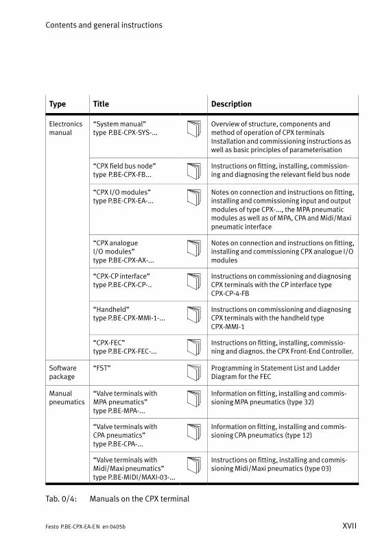
Type Title Description
Electronicsmanual
�System manual"type�P.BE−CPX−SYS−...
Overview of structure, components andmethod of operation of CPX terminalsInstallation and commissioning instructions aswell as basic principles of parameterisation
�CPX field bus node"type�P.BE−CPX−FB...
Instructions on fitting, installing, commission�ing and diagnosing the relevant field bus node
�CPX I/O modules"type P.BE−CPX−EA−...
Notes on connection and instructions on fitting,installing and commissioning input and outputmodules of type CPX−..., the MPA pneumaticmodules as well as of MPA, CPA and Midi/Maxipneumatic interface
�CPX analogueI/O�modules"type�P.BE−CPX−AX−...
Notes on connection and instructions on fitting,installing and commissioning CPX analogue I/Omodules
�CPX−CP interface"type P.BE−CPX−CP−..
Instructions on commissioning and diagnosingCPX terminals with the CP interface typeCPX−CP−4−FB
�Handheld"type P.BE−CPX−MMI−1−...
Instructions on commissioning and diagnosingCPX terminals with the handheld typeCPX−MMI−1
�CPX−FEC"type P.BE−CPX−FEC−...
Instructions on fitting, installing, commissio�ning and diagnos. the CPX Front−End Controller.
Softwarepackage
�FST" Programming in Statement List and LadderDiagram for the FEC
Manualpneumatics
�Valve terminals withMPA�pneumatics"type P.BE−MPA−...
Information on fitting, installing and commis�sioning MPA pneumatics (type 32)
�Valve terminals withCPA�pneumatics"type P.BE−CPA−...
Information on fitting, installing and commis�sioning CPA pneumatics (type 12)
�Valve terminals withMidi/Maxi pneumatics"type P.BE−MIDI/MAXI−03−...
Instructions on fitting, installing and commis�sioning Midi/Maxi pneumatics (type 03)
Tab.�0/4: Manuals on the CPX terminal

Contents and general instructions
XVIII Festo P.BE−CPX−EA−EN en 0405b
The following product−specific terms and abbreviations areused in this manual:
Term/abbreviation Meaning
CPX modules Common term for the various modules which can be incorporated in aCPX�terminal
CPX terminal Modular, electric terminal type 50
DIL switches Dual−in−line switches usually consist of several switch elements withwhich settings can be made.
Field bus node Provides the connection to certain field buses. Transmits control signalsto the connected modules and monitors their functioning.
I Digital input
I module CPX input module
I/O diagnostic interface The I/O diagnostic interface is a bus−independent diagnostic interface atI/O level which enables access to internal data of the CPX terminal.
I/O modules Common term for the CPX modules which provide digital inputs andoutputs (CPX input modules and CPX output modules).
I/Os Digital inputs and outputs
Manifold sub−base Lower part of housing of a module or sub−base for electrical linking of themodule with the terminal.
MPA pneumatic module Pneumatic module which provides digital outputs for the fitted valves(valve solenoid coils).
O Digital output
O module CPX output module
PLC/IPC Programmable logic controller/industrial PC
Pneumatic interface The pneumatic interface is the interface between the modular electricalperipherals and the pneumatics.
Status bits Internal inputs which supply coded common diagnostic messages.
Sub−base Exchangeable upper part of housing of modules with connectiontechniques.
Tab.�0/5: Product−specific abbreviations

Pneumatic interfaces
1−1Festo P.BE−CPX−EA−EN en 0405b
Chapter 1
Type VMPA−FB−EPL−...CPX−GP−03−4.0CPX−GP−CPA−10CPX−GP−CPA−14

1. Pneumatic interfaces
1−2 Festo P.BE−CPX−EA−EN en 0405b
Contents
1. Pneumatic interface 1−1 . . . . . . . . . . . . . . . . . . . . . . . . . . . . . . . . . . . . . . . . . . . .
1.1 Function of the pneumatic interface 1−4 . . . . . . . . . . . . . . . . . . . . . . . . . . . . . . . .
1.1.1 Display and connecting elements 1−6 . . . . . . . . . . . . . . . . . . . . . . . . . . .
1.2 Fitting 1−8 . . . . . . . . . . . . . . . . . . . . . . . . . . . . . . . . . . . . . . . . . . . . . . . . . . . . . . . .
1.3 Settings for configuring the pneumatics 1−9 . . . . . . . . . . . . . . . . . . . . . . . . . . . . .
1.4 Installation 1−14 . . . . . . . . . . . . . . . . . . . . . . . . . . . . . . . . . . . . . . . . . . . . . . . . . . . .
1.5 Commissioning instructions 1−15 . . . . . . . . . . . . . . . . . . . . . . . . . . . . . . . . . . . . . .
1.6 Diagnosis 1−19 . . . . . . . . . . . . . . . . . . . . . . . . . . . . . . . . . . . . . . . . . . . . . . . . . . . . .
1.6.1 Fault messages of the pneumatic interfaces 1−20 . . . . . . . . . . . . . . . . . .
1.6.2 LED display 1−21 . . . . . . . . . . . . . . . . . . . . . . . . . . . . . . . . . . . . . . . . . . . .
1.6.3 Fault treatment and parametrizing 1−23 . . . . . . . . . . . . . . . . . . . . . . . . . .

1. Pneumatic interfaces
1−3Festo P.BE−CPX−EA−EN en 0405b
Contents of this chapter This chapter describes the CPX pneumatic interfaces. Thereproduction, distribution and utilization of this document aswell as the communicaton of its contents to others withoutexpress authorization is prohibited. Offenders will be heldliable for the payment of damages. All rights reserved in theevent of the grant of a patent, utility module or design.
In a CPX terminal, a CPX pneumatic interface connects themodular electric peripherals of type CPX with the pneumaticsof type 03 (Midi/Maxi), type 12 (CPA) or type 32 (MPA).
You should read this chapter if your CPX terminal is fitted witha pneumatic interface or with pneumatic modules.
Further information Information on fitting the complete CPX terminal, the powersupply as well as general instructions on configuring andparametrizing can be found in the CPX system manual.
Information on the pneumatics of the CPX terminal can befound in the relevant pneumatics manual.
Information on the address assignment as well as on commis�sioning can be found in the relevant manual for the field busnode or the function module.

1. Pneumatic interfaces
1−4 Festo P.BE−CPX−EA−EN en 0405b
1.1 Function of the pneumatic interface
The CPX pneumatic interfaces provide the connecction to thepneumatic modules in the CPX terminal. By means of the fitted valves, the pneumatic modules enablepneumatic actuators to be controlled.
A distinction is made between the following types:
Type Description
VMPA−FB−EPL−... Pneumatic interface forconnecting the modular electricperipherals type 50 (CPX) tovalve terminals type 32 (MPA).
CPX−GP−03−4.0 Pneumatic interface forconnecting the modular electricperipherals type 50 (CPX) tovalve terminals type 03 (Midi/Maxi).
CPX−GP−CPA−10 Pneumatic interface forconnecting the modular electricperipherals type 50 (CPX) tovalve terminals type 12 of size10 (CPA10).
CPX−GP−CPA−14 Pneumatic interface forconnecting the modular electricperipherals type 50 (CPX) tovalve terminals type 12 of size14 (CPA14).
Tab.�1/1: Overview of pneumatic interfaces

1. Pneumatic interfaces
1−5Festo P.BE−CPX−EA−EN en 0405b
MPA pneumatics From a technical point of view, the individual MPA pneu�matic modules each represent an electric module with e.g.8�digital outputs for controlling the fitted valves (see chapter 2).
Please noteThe pneumatic interface for MPA pneumatics merely pro�vides the mechanical and electrical connections to the MPApneumatic modules.
From the point of view of the CPX terminal, this pneumaticinterface does not count as an electric module.
Midi/Maxi pneumatics or CPA pneumatics
From a technical point of view, the pneumatic interfaces forMidi/Maxi pneumatics or CPA pneumatics represent an elec�tric module with a variable (configurable) number of digitaloutputs for controlling the fitted valves (see chapter follow�ing sections).

1. Pneumatic interfaces
1−6 Festo P.BE−CPX−EA−EN en 0405b
1.1.1 Display and connecting elements
MPA pneumatics The pneumatic interface for MPA pneumatics (type 32) hasthe following display and connecting elements:
1 Connecting plug forthe MPA pneumaticmodules
2 Inscription field
3 Connecting plug forthe CPX manifoldsub−bases
1
2
3
Fig.�1/1: Display and connecting elements of the pneumatic interface for MPApneumatics

1. Pneumatic interfaces
1−7Festo P.BE−CPX−EA−EN en 0405b
Midi/Maxi or CPA pneumatics
The pneumatic interfaces for Midi/Maxi or CPA pneumaticshave the following display and connecting elements:
1 Pneumatic interfacefor Midi/Maxi pneu�matics (type�03)
2 Pneumatic interfacefor CPA pneumatics(type 12 � here size10)
3 Connecting plug tothe valves
4 Fault LED (red)
5 DIL switch under atransparent cover
6 Inscription fields
7 Connecting plug forthe CPX manifoldsub−bases
1 2
3
4
5
6
3
4
5
7 7
Fig.�1/2: Display and connecting elements of the pneumatic interfaces for Midi/Maxi orCPA pneumatics
Use the identification signs type IBS 6x10 for marking on thepneumatic interface for CPA pneumatics.
1. Pneumatic interfaces
1−8 Festo P.BE−CPX−EA−EN en 0405b
1.2 Fitting
WarningSudden unexpected movements of the connected actua�tors and uncontrollable movements of loose tubing cancause injury to human beings and damage to property.
Before carrying out installation and/or maintenance work,switch off the following:
� the compressed air supply
� the operating and load voltage supplies.
For extending or converting the CPX terminal, as well as forreplacing a pneumatic interface, it is necessary to dismantlethe terminal which is screwed together. Instructions on thisprocedure can be found in the CPX system manual. Instructions on extending or converting the pneumatic mod�ules can be found in the relevant pneumatics manual.
The setting of the DIL switches on the pneumatic interfacesfor Midi/Maxi or CPA pneumatics for the configuration of thepneumatics (valves used) can be undertaken on the fittedCPX terminal.

1. Pneumatic interfaces
1−9Festo P.BE−CPX−EA−EN en 0405b
1.3 Settings for configuring the pneumatics
Midi/Maxi or CPA pneumatics
Settings for configuring the pneumatics are only requiredwith the pneumatic interfaces for Midi/Maxi or CPA pneu�matics.
No settings are required for MPA pneumatics.
CautionAfter conversion or extension of the Midi/Maxi or CPApneumatics, the number of output addresses assigned bythe pneumatics must be set on a DIL switch on the pneu�matic interface.
CPX terminals are fitted with various valves and electric mod�ules according to the customer’s wishes.
The size of the valve address range with Midi/Maxi or CPApneumatics does not change after extension/conversion ofthe valves, providing sufficient address space has been re�served for the extension. The valve address range is set witha DIL switch. The DIL switch is located under the transparentcover on the pneumatic interface.
WarningSudden unexpected movements of the connected actua�tors and uncontrollable movements of loose tubing cancause injury to human beings and damage to property.
Before carrying out installation and/or maintenance work,switch off the following:
� the compressed air supply
� the operating and load voltage supplies.

1. Pneumatic interfaces
1−10 Festo P.BE−CPX−EA−EN en 0405b
CautionModules may be damaged if they are not handledcorrectly.
· Do not touch the electrical contacts of the modules.
· Observe the regulations for handling electrostaticallysensitive components.
· Discharge yourself of static electricity before fitting orremoving the modules in order to protect the modulesagainst static discharges.
Please noteHandle all modules and components of the CPX terminalwith great care. Observe especially the following:
· Screws must be fitted correctly (otherwise threads maybe damaged) screws must be tightened at first only byhand screws must be inserted so that the self−boringthreads can be used.
· The specified torques must be observed.
· Screws must be fitted without offset and mechanicalstress.
· Testing the seals for damage (IP65).
· Connecting surfaces must be clean (sealing effect, avoidleakage and contact faults).
The screw connection between the cover and the lowerpart of the CPA pneumatic interface has been designed forat least 10 fitting/dismantling cycles.
Removing the cover
1. Loosen the screws in the cover with a Torx screwdriversize T10.
2. Carefully lift up the cover.

1. Pneumatic interfaces
1−11Festo P.BE−CPX−EA−EN en 0405b
3. Set the DIL switch elements as shown in the followingtable. Use a suitable tool for setting the DIL switches, e.g.a small screwdriver.
1 Printed circuitboard
2 Fault LED
3 DIL switches forconfiguring thepneumatics
1
2
3
Fig.�1/3: DIL switches on the pneumatic interface (here for CPA pneumatics)
The DIL switch possesses 8 switch elements. These are num�bered from 1...8. The positions OPEN (CPA) or ON (Midi/Maxi)are marked.
Rules for setting
� If the number of valve solenoid coils fitted is less than thenumber of output addresses assigned by DIL switch, thesuperfluous addressses will be reserved for later exten�sions (if the maximum number of valves are fitted, someoutput addresses will therefore be unused).
� Modifications to the configuration will not become effec�tive until the operating voltage is switched on again.
� 8 further output addresses per switch element arereserved for valves in the address range.
� Decisive for the assigned address range is the setting ofthe higher−value DIL switch in the position ON (closed).

1. Pneumatic interfaces
1−12 Festo P.BE−CPX−EA−EN en 0405b
Setting of the DIL switch
DIL switch setting Assigned addresses
Midi/Maxi CPA Switch
12
34
56
78
12345678
OPEN
8: reserved7: reserved6: reserved5: reserved4: OFF/OPEN3: OFF/OPEN2: OFF/OPEN1: ON/CLOSED
8 outputs for valves1
23
45
67
8
12345678
OPEN
8: reserved7: reserved6: reserved5: reserved4: OFF/OPEN3: OFF/OPEN2: ON/CLOSED1: as desired
16 outputs for valves
12
34
56
78
12345678
OPEN
8: reserved7: reserved6: reserved5: reserved4: OFF/OPEN3: ON/CLOSED2: as desired1: as desired
24 outputs for valves(factory setting forCPA�1))� With CPA: only 22 can
be used 2)
12
34
56
78 Setting
notpermitted
8: reserved7: reserved6: reserved5: reserved4: ON3: as desired2: as desired1: as desired
32 outputs for valves(factory setting for Midi/Maxi 1))� With Midi/Maxi: only
26 can be used 2)
1) Depending on CPX equipment and field bus node, see followingnote.
2) Additionally assigned output addresses remain unused.
Tab.�1/2: DIL switch setting
1. Pneumatic interfaces
1−13Festo P.BE−CPX−EA−EN en 0405b
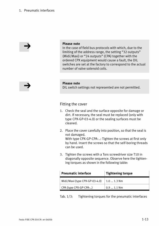
Please noteIn the case of field bus protocols with which, due to thelimiting of the address range, the setting �32 outputs"(Midi/Maxi) or �24 outputs" (CPA) together with theordered CPX equipment would cause a fault, the DILswitches are set at the factory to correspond to the actualnumber of valve solenoid coils.
Please noteDIL switch settings not represented are not permitted.
Fitting the cover
1. Check the seal and the surface opposite for damage ordirt. If necessary, the seal must be replaced (only withtype CPX−GP−03−4.0) or the sealing surfaces must becleaned.
2. Place the cover carefully into position, so that the seal isnot damaged. With type CPX−GP−CPA−..: Tighten the screws at first onlyby hand. Insert the screws so that the self−boring threadscan be used.
3. Tighten the screws with a Torx screwdriver size T10 indiagonally opposite sequence. Observe here the tighten�ing torques as shown in the following table:
Pneumatic interface Tightening torque
Midi/Maxi (type CPX−GP−03−4.0) 1.0 ... 1.3 Nm
CPA (type CPX−GP−CPA−..) 0.9 ... 1.1 Nm
Tab.�1/3: Tightening torques for the pneumatic interfaces

1. Pneumatic interfaces
1−14 Festo P.BE−CPX−EA−EN en 0405b
1.4 Installation
Instructions on installing the pneumatics can be found in therelevant pneumatics manual. Instructions on installing the electric components can befound in the CPX system manual. Instructions on addressing the valve solenoid coils, as well asfurther instructions on installing the electric components canbe found in the relevant manual for the field bus node.
Power supply
The 24 V supply for the valves is provided via the load voltagefor the valves of the CPX terminal (Vval).
The power supply for the electronics of the pneumatic inter�face is provided via the operating voltage supply for the elec�tronics/sensors (Vel/sen).
Address assignment within the pneumatic modules
Instructions on assigning the addresses to the individualvalve solenoid coils with Midi/Maxi or CPA pneumatics can befound in the relevant pneumatics manual.
Instructions on assigning the addresses to the individualvalve solenoid coils with MPA pneumatic modules can befound in chapter 2.
Protection class
When fitted completely, the pneumatic interfaces with valveterminal pneumatics comply with protection class IP65 (seeappendix A.1).

1. Pneumatic interfaces
1−15Festo P.BE−CPX−EA−EN en 0405b
1.5 Commissioning instructions
Midi/Maxi or CPA pneumatics
The reaction of the pneumatic interfaces for Midi/Maxi orCPA pneumatics can be parametrized. The following tableprovides an overview of the parameters for the pneumaticinterfaces.
With the MPA pneumatics, parametrizing takes place via theindividual MPA pneumatic modules (module−orientated, seechapter 2).
Further information on parametrizing can be found in thesystem manual and in the manual for the field bus node.
Please noteActivate the wire fracture monitoring only for outputswhich have a valve solenoid coil.
If the wire fracture monitoring is activated for an outputwhich does not have a valve solenoid coil, the CPX terminalwill register the fault �Wire fracture" when it is switchedon, due to the alleged defective valve solenoid coil.

1. Pneumatic interfaces
1−16 Festo P.BE−CPX−EA−EN en 0405b
Parameters of the pneumatic interfaces types CPX−GP−03−4.0 and CPX−GP−CPA−..
Module parameters: Monitoring the CPX module
Function no. 4828 + m * 64 + 0 m = module number (0 ... 47)
Description Monitoring of the possible faults can be activated or deactivated (suppressed)for each module independently. Active monitoring causes the following: The faultis:� sent to the CPX field bus node� shown on the module common fault LED.
Bit23
MonitoringDescriptionUndervoltage at valves (Vval)Short circuit at valves (SCV)
[Monitor]
[Monitor Vval][Monitor SCV]
Values 1 = active0 = inactivePresetting: bit 2: active
bit 3: inactive
[Active][Inactive]
Note Monitoring can also be set for the complete CPX terminal (see CPX system manual).
Tab.�1/4: Monitoring the CPX module

1. Pneumatic interfaces
1−17Festo P.BE−CPX−EA−EN en 0405b
Module parameters: Monitoring wire fracture channel x (only CPA pneumatics)
Function no.� channel 0 ... 7:� channel 8 ... 15:� channel 16 ... 23:� channel 24 ... 31:
4828 + m * 64 + 6 m = module number (0 ... 47)4828 + m * 64 + 74828 + m * 64 + 84828 + m * 64 + 9
Description Defines whether the wire fracture monitoring for the appropriate channel isenabled or disabled (CPA: channel 0 ... 21).
Monitoring wire fracture output channel ...0 = inactive (presetting)1 = active
[Monitor open circuit Out Ch ...][Inactive][Active]
Note With the wire fracture monitoring, a non−existent valve or a wire fracture(connection fault between the pneumatic interface and the valve coil) isrecognized.
Tab.�1/5: Monitoring wire fracture channel x (channel−specific)
Module parameters: Fail safe channel x
Function no. Access to this module parameter is made via protocol−specific functions (see manual for field bus node).
Description Fault mode channel x: Hold last stateFault state (presetting)
Fault state channel x: Set outputReset output (presetting)
Note With the so−called Fail−safe parametrizing, you can defines the signal statuswhich outputs should assume in the event of field bus communication faults (see also CPX system manual).
Tab.�1/6: Fail safe channel x (channel−specific)

1. Pneumatic interfaces
1−18 Festo P.BE−CPX−EA−EN en 0405b
Module parameters: Idle mode channel x
Function no. Access to this module parameter is made via protocol−specific functions (see manual for field bus node).
Description Only relevant with certain field bus protocols.Idle mode channel x: Hold last state
Idle state (presetting)Fault state channel x: Set output
Reset output (presetting)
Note With the so−called Idle mode parametrizing, you can define the signal statuswhich outputs should assume when they change to the idle state (see also CPXsystem manual).This parameter is not available with all field bus protocols.
Tab.�1/7: Idle mode channel x (channel−specific)
Module parameters: Force channel x
Function no. Access to this module parameter is made via protocol−specific functions (see manual for field bus node).
Description Force mode outputs channel x: disabled (presetting)Force state
Force state outputs channel x: Set signalReset signal (presetting)
Note The function Force enables the manipulation of signal states disconnected fromactual operating states (see also CPX system manual).
Tab.�1/8: Force channel x (channel−specific)

1. Pneumatic interfaces
1−19Festo P.BE−CPX−EA−EN en 0405b
1.6 Diagnosis
Midi/Maxi or CPA pneumatics
Specific faults of the pneumatic interfaces for Midi/Maxi orCPA pneumatics are registered or suppressed, dependingon the module parametrizing.
The faults are shown on the spot by means of the fault LEDsand can be evaluated, if necessary, with the handheld (MMI).
Depending on the module parametrizing, the faults are regis�tered with the field bus node and can be evaluated there ac�cording to the field bus protocol used.
With the MPA pneumatics, diagnosis takes place via theindividual MPA pneumatic modules (module−orientated,see�chapter 2).

1. Pneumatic interfaces
1−20 Festo P.BE−CPX−EA−EN en 0405b
1.6.1 Fault messages of the pneumatic interfaces
Midi/Maxi or CPA pneumatics
The pneumatic interfaces for Midi/Maxi or CPA pneumaticscan register the following standard faults:
Fault number Description Fault treatment
5 Fault in load voltage for valvesLoad voltage at valves (Vval) notapplied or too low. 1)
· Check load voltage
11 Short circuit fault at valve 2)
Short circuit/overload at valve· Make sure that the valves are fitted
correctly and that the electricalconnections are OK.
· If necessary, replace the valve.
13 Wire fracture fault 2)
Quiescent current monitoring of thevalve solenoid coils (open load, onlyactive with 0−signal).Only relevant for CPA pneumatics.
· Make sure that the valves are fittedcorrectly and that the electricalconnections are OK.
· If necessary, replace the valve.· Correct any incorrect parametrizing
(e.g. with reserved valve locations/blanking plates, see section 1.3).
1) Tolerance range of the load voltage supply Vval see Technical Specifications in the Appendix..2) Number of the faulty channel:see module diagnostic data.
Tab.�1/9: Fault messages of the pneumatic interfaces for Midi/Maxi or CPA pneumatics

1. Pneumatic interfaces
1−21Festo P.BE−CPX−EA−EN en 0405b
1.6.2 LED display
Midi/Maxi or CPA pneumatics
There is an LED under the transparent cover of the pneu�matic interfaces for diagnosing the pneumatic interfaces forMidi/Maxi or CPA pneumatics.
1 Fault LED (red) CPX−GP−CPA−...
1
CPX−GP−03−4.0
1
Fig.�1/4: LED display of the pneumatic interfaces

1. Pneumatic interfaces
1−22 Festo P.BE−CPX−EA−EN en 0405b
Fault LED
Midi/Maxi or CPA pneumatics
The red fault LED of the pneumatic interfaces for Midi/Maxior CPA pneumatics shows the faults of the pneumatic inter�face, depending on the parametrizing.
Fault LED(red)
Sequence Status Faultnumber
Faulttreatment
LED is out
ON
OFF
Faultless operation � None
LED lights up
ON
OFFFault in load voltage for valvesLoad voltage at valves (Vval) notapplied or too low.
5 See section1.6.1, Tab.�1/9
LED lights up
Short circuit fault at valveShort circuit/overload at valve
11
Wire fracture faultQuiescent current monitoring of thevalve solenoid coils (open load,only active with 0−signal).Only relevant for CPA pneumatics.
13
Tab.�1/10: Fault LED of pneumatic interfaces
The fault shown by the red fault LED is transmitted by thepneumatic interface to the field bus node (providing it is notparametrized otherwise).
Status LEDs of the valve solenoid coils
The yellow status LEDs on the valve solenoid coils show thestatus of the relevant output (see relevant pneumaticsmanual).

1. Pneumatic interfaces
1−23Festo P.BE−CPX−EA−EN en 0405b
1.6.3 Fault treatment and parametrizing
Midi/Maxi or CPA pneumatics
The following diagram shows the fault treatment in the pneu�matic interfaces for Midi/Maxi or CPA pneumatics. With theappropriate module parameters, shown in the diagram as aswitch, the further message and display of the faults can besuppressed if required. A description of the parameters canbe found under section 1.5.
2
Fault no. 5
Fault in loadvoltage forvalves
Fault message tofield bus node
...
Fault no. 11
Short circuitfault at valve,channel 0
Fault no. 13
Wire fracturefault, chan�nel 0
Fault no. 11
Short circuitfault at valve,channel x
Fault no. 13
Wire fracturefault, chan�nel x
MonitoringVval
MonitoringSCV
MonitoringWire fracturechannel 0
MonitoringWire fracturechannel 1
Module fault LED
3
1
...
...0 1 0 1 0 1 0 1
1 Module parameter (switch position represented = default setting)
2 Module−specific fault
3 Channel−specific fault (fault no. 13 only with CPA pneumatics)
Fig.�1/5: Principle of fault treatment in the pneumatic interfaces for Midi/Maxi or CPApneumatics

1. Pneumatic interfaces
1−24 Festo P.BE−CPX−EA−EN en 0405b

MPA pneumatic modules
2−1Festo P.BE−CPX−EA−EN en 0405b
Chapter 2
Electronik modulestype VMPA1−FB−EMG−8
VMPA1−FB−EMS−8VMPA2−FB−EMG−4VMPA2−FB−EMS−4

2. MPA pneumatic modules
2−2 Festo P.BE−CPX−EA−EN en 0405b
Contents
2. MPA pneumatic modules 2−1 . . . . . . . . . . . . . . . . . . . . . . . . . . . . . . . . . . . . . . . .
2.1 Function of the MPA pneumatic modules 2−4 . . . . . . . . . . . . . . . . . . . . . . . . . . . .
2.1.1 Display and connecting elements 2−6 . . . . . . . . . . . . . . . . . . . . . . . . . . .
2.2 Fitting 2−7 . . . . . . . . . . . . . . . . . . . . . . . . . . . . . . . . . . . . . . . . . . . . . . . . . . . . . . . .
2.3 Installation 2−11 . . . . . . . . . . . . . . . . . . . . . . . . . . . . . . . . . . . . . . . . . . . . . . . . . . . .
2.4 Commissioning instructions 2−15 . . . . . . . . . . . . . . . . . . . . . . . . . . . . . . . . . . . . . .
2.5 Diagnosis 2−18 . . . . . . . . . . . . . . . . . . . . . . . . . . . . . . . . . . . . . . . . . . . . . . . . . . . . .
2.5.1 Fault messages of the MPA pneumatic modules 2−18 . . . . . . . . . . . . . . .
2.5.2 LED display 2−19 . . . . . . . . . . . . . . . . . . . . . . . . . . . . . . . . . . . . . . . . . . . .
2.5.3 Fault treatment and parametrizing 2−22 . . . . . . . . . . . . . . . . . . . . . . . . . .

2. MPA pneumatic modules
2−3Festo P.BE−CPX−EA−EN en 0405b
Contents of this chapter This chapter describes the MPA pneumatic modules for CPXterminals.
MPA pneumatic modules provide the following in a CPXterminal: digital outputs for the valves fitted (valve solenoidcoils). The modules can be adapted to the specific applicationby means of various valve plates.
You should read this chapter if your CPX terminal is fitted withMPA pneumatics.
Further information Information on fitting the complete CPX terminal, the powersupply as well as general instructions on configuring andparametrizing can be found in the CPX system manual.
Information on the pneumatics of the CPX terminal, especiallythe valve plates available, can be found in the relevant pneu�matics manual.
Information on the address assignment as well as on commis�sioning can be found in the relevant manual for the field busnode or the function module.

2. MPA pneumatic modules
2−4 Festo P.BE−CPX−EA−EN en 0405b
2.1 Function of the MPA pneumatic modules
The MPA pneumatic modules provide digital outputs in theCPX terminal for controlling the valves fitted and thus enablepneumatic actuators to be controlled.
From a technical point of view, the individual MPA pneumatic
modules each represent an individual electric module withdigital outputs.
Maximum 8 MPA pneumatic modules are permitted per CPXterminal. Therefore up to 64 valve solenoid coils (exclusivelyMPA1) or 32 valve solenoid coils (exclusively MPA2) are poss�
ible.
MPA pneumaticmodules
Type designation Description
� VMPA1−FB−EM..−8
� VMPA1−FB−AP−4−1� VMPA1−M1H−...
� VMPA1−RP
MPA1 pneumatic module: Output module with MPA pneumatics, consisting of:� electronic module with 8 outputs (valve solenoid
coils)� sub−base for 4 valve plates,� valve plates (or corresponding pneumatic
components) or� cover plates for reserve locations.
� VMPA2−FB−EM..−4
� VMPA2−FB−AP−2−1� VMPA2−M1H−...
� VMPA2−RP
MPA2 pneumatic module: Output module with MPA pneumatics, consisting of:� electronic module with 4 outputs (valve solenoid
coils)� sub−base for 2 valve plates,� valve plates (or corresponding pneumatic
components) or� cover plates for reserve locations.
Tab.�2/1: MPA pneumatic modules

2. MPA pneumatic modules
2−5Festo P.BE−CPX−EA−EN en 0405b
1 Valve plates orblanking plates
2 Electronic module
3 Sub−base
1
2
3
Fig.�2/1: Components of the MPA pneumatic modules (example MPA1)
The electrical function of an MPA pneumatic module is de�fined by the electronic module used. A distinction is madebetween the following types of MPA electronic modules:
Type Description
VMPA1−FB−EMG−8 Electronic module with 8 out�puts (valve solenoid coils),with electrical isolation
VMPA1−FB−EMS−8 Electronic module with 8 out�puts (valve solenoid coils),without electrical isolation
VMPA2−FB−EMG−4 Electronic module with 4 out�puts (valve solenoid coils),with electrical isolation
VMPA2−FB−EMS−4 Electronic module with 4 out�puts (valve solenoid coils),without electrical isolation
Tab.�2/2: Overview of MPA electronic modules

2. MPA pneumatic modules
2−6 Festo P.BE−CPX−EA−EN en 0405b
2.1.1 Display and connecting elements
The MPA pneumatic modules possess the following displayand connecting elements:
1 LEDs:� outputs (yellow)� fault (red)
2 Connecting plug forfurther MPA pneu�matic modules
3 Manual override
4 Identification platewith inscription field
5 Connecting plug forthe CPX pneumaticinterface or forfurther MPA pneu�matic modules
1 2
3
4
5 1 3 5 7
0 2 4 6
Fig.�2/2: Display and connecting elements (example MPA1)
Use identification plate type VMPA1−ST−1−4 for labelling theMPA pneumatic modules.

2. MPA pneumatic modules
2−7Festo P.BE−CPX−EA−EN en 0405b
2.2 Fitting
WarningSudden unexpected movements of the connected actua�tors and uncontrollable movements of loose tubing cancause injury to human beings and damage to property.
Before carrying out installation and/or maintenance work,switch off the following:
� the compressed air supply
� the operating and load voltage supplies.
For extending or converting the CPX terminal, as well as forreplacing a pneumatic interface, it is necessary to dismantlethe terminal which is screwed together. Instructions on thisprocedure can be found in the CPX system manual. Instructions on extending or converting the MPA pneumaticmodules can be found in the relevant pneumatics manual.
You can replace electronic modules or valve plates withoutthe need to dismantle the CPX terminal.
CautionModules may be damaged if they are not handledcorrectly.
· Do not touch the electrical contacts of the modules.
· Observe the regulations for handling electrostaticallysensitive components.
· Discharge yourself of static electricity before fitting orremoving the modules in order to protect the modulesagainst static discharges.

2. MPA pneumatic modules
2−8 Festo P.BE−CPX−EA−EN en 0405b
Please noteHandle all modules and components of the CPX terminalwith great care. Observe especially the following:
· Screws must be fitted correctly (otherwise threads maybe damaged). Screws must be tightened at first only byhand screws must be inserted so that the self−boringthreads can be used.
· The specified torques must be observed.
· Screws must be fitted without offset and mechanicalstress.
· The seals must be checked for damage (IP65)
· Connecting surfaces must be clean (sealing effect,avoidance of leakage and contact faults).
Dismantling the electronic module
1. Use a screwdriver with a narrow blade to loosen thefastening screws of all valve plates and blanking platesand remove the plates from the sub−bases.
2. Loosen the screws with which the electronic module isfastened to the sub−base.
3. Pull the electronic module upwards out of the body of thesub−base.

2. MPA pneumatic modules
2−9Festo P.BE−CPX−EA−EN en 0405b
1 Fastening screws forthe valve plate orblanking plate
2 Valve plates orblanking plates
3 Flat seals
4 Electronic module
5 Sub−base
6 Identification plate
7 Sealing rim of theelectronic module
8 Fastening screws ofthe electronic module
9 2 conical ring sealsper valve plate orblanking plate
1
2
3
4
5
6
9
8
7
Fig.�2/3: Dismantling and fitting the electronic module (example MPA1)

2. MPA pneumatic modules
2−10 Festo P.BE−CPX−EA−EN en 0405b
Fitting the electronic module
CautionReplace an electronic module only by an electronic moduleof the same type (see section 2.3).
Please noteBefore fitting, check the status and the position of thefollowing seals:
� sealing rim of the electronic module
� ring seal of the electric contacts
� flat seal of the valve plates or blanking plates.
1. Place the electronic module in the sub−base
2. Tighten the screws of the electronic module with 0.2 ... 0.25�Nm.
3. Then fit the valve plates or blanking plates. Check the sealof the valve plates or blanking plates for damage. Ifnecessary, replace damaged seals.
4. Make sure that the seals are fitted correctly. The flat seal between the sub−base and the componentmust fit into the recess in the component. The ring sealsbetween the electronic module and the component areconical. They must be fitted onto the guide pins of thecomponent, so that during fitting the cone slides easilyinto the appropriate recess in the electronic module(see�Fig.�2/3).
5. Place the components on the sub−base.
6. Screw the components at first slightly and then tightenwith 0.2 ... 0.25 Nm.

2. MPA pneumatic modules
2−11Festo P.BE−CPX−EA−EN en 0405b
2.3 Installation
Instructions on installing the pneumatic components can befound in the pneumatics manual type P−BE−MPA−... .Instructions on installing the electric components can befound in the CPX system manual.Instructions on addressing the valve solenoid coils, as well asfurther instructions on installing the electric components canbe found in the relevant manual for the field bus node.
Power supply
The 24 V supply for the valves is provided via the load voltagefor the valves of the CPX terminal (Vval).
The power supply for the electronic modules is provided viathe operating voltage supply for the electronics/sensors(Vel/sen).
CautionDamage to components and malfunctioning
It is not permitted to use a manifold sub−base for valvesupply type CPX−GE−EV−V for supplying voltage to MPApneumatic modules with electronic modules withoutelectrical isolation.
· If your MPA pneumatics are fitted with electronic mod�ules of type VMPA1−FB−EMS−8 or VMPA2−FB−EMS−4, useonly system supply module type CPX−GE−EV−S for sup�plying the MPA pneumatics.

2. MPA pneumatic modules
2−12 Festo P.BE−CPX−EA−EN en 0405b
Note that MPA electronic modules may only be supplied withpower via the following supply modules:
MPA electronic module Permitted supply modules(type)
� VMPA1−FB−EMS−8� VMPA2−FB−EMS−4(in each case withoutelectrical isolation)
� System supply module (CPX−GE−EV−S)
� VMPA1−FB−EMG−8� VMPA2−FB−EMG−4(in each case with electricalisolation)
� Valve supply module (CPX−GE−EV−V)or
� System supply module (CPX−GE−EV−S) 1)
1) If the system supply module is used, the electrical isolation willnot function.
In the case of electronic modules with electrical isolation typeVMPA1−FB−EMG−8 or VNPA2−FB−EMG−4, Vel/sen and Vval arecompletely electrically isolated. In conjunction with a mani�fold sub−base with valve supply type CPX−GE−EV−V, it is poss�ible to switch off the valve supply voltage at all poles.

2. MPA pneumatic modules
2−13Festo P.BE−CPX−EA−EN en 0405b
1 2 3 4 5 6
8
9
aJ
1 2 3 424�V 0�V FU24�V
2 3 40�V FU24�V
1n.c.
24 Vel/sen0 Vel/sen
24 V out0 V out
24 V val0 V val
FU
24 V val0 V val
7
1 Manifold sub−base with system supply
2 Manifold sub−base without supply
3 Manifold sub−base with valve supply
4 MPA pneumatic interface
5 MPA pneumatic module with electricalisolation Only useful with separate load supplyvia manifold sub−base with valvesupply
6 MPA pneumatic module withoutelectrical isolation Not permitted with load supply viamanifold sub−base with valve supply
7 Load voltage for valves (Vval)
8 Load voltage for digital outputs (Vout)
9 Operating voltage for electronics andsensors (Vel/sen)
aJ 5 further rails
Fig.�2/4: Power supply circuit for MPA pneumatic modules
Protection class
When fitted completely, the MPA pneumatic modules complywith protection class IP65 (see appendix A.1).

2. MPA pneumatic modules
2−14 Festo P.BE−CPX−EA−EN en 0405b
Address assignment within the pneumatic modules
An MPA1 pneumatic module always occupies 8 outputaddresses; an MPA2 pneumatic module always occupies4�output addresses.
Each valve location occupies 2 addresses, irrespective ofwhich valve plate is fitted or whether a blanking plate isfitted. The following assignment applies:
� solenoid coil 14 occupies the lower−value address
� solenoid coil 12 occupies the higher−value address.
1 2
534 76
Ox+
2
Ox+
4
Ox+
6
Ox+
1
Ox+
3
Ox+
5
Ox+
7
Oy+
1
Oy+
0
Oy+
3
Oy+
2
12 14 12 14 14 12 14 12 14
Ox+
0
12
14
5
3
4
3
4
1 MPA1 pneumatic module
2 MPA2 pneumatic module
3 Addr. of coils 14 (channel 0, 2, 4, 6)
4 Addr. of coils 12 (channel 1, 3, 5, 7)
5 Valve plates with two solenoid coils
6 Valve plates with one solenoid coil(addresses Ox+5 unused)
7 Blanking plate
Fig.�2/5: Example: Address assignment of the MPA pneumatic modules (top view)

2. MPA pneumatic modules
2−15Festo P.BE−CPX−EA−EN en 0405b
2.4 Commissioning instructions
The reaction of the MPA pneumatic modules can be parame�trized. The following table provides an overview of the para�meters for the MPA pneumatic modules.
Further information on parametrizing can be found in thesystem manual and in the manual for the field bus node.
Parameters for the MPA pneumatic modules withelectronicmodule type VMPA..−FB−EM..−...
Module parameters: Monitoring the CPX module
Function no. 4828 + m * 64 + 0 m = module number (0 ... 47)
Description Monitoring of the possible faults can be activated or deactivated (suppressed)for each module independently. Active monitoring causes the following: The fault is:� sent to the CPX field bus node� shown on the module common fault LED.
Bit2
MonitoringDescriptionUndervoltage at valves (Vval)
[Monitor]
[Monitor Vval]
Values 1 = active (presetting)0 = inactive
[Active][Inactive]
Note Monitoring can also be set for the complete CPX terminal (see CPX system manual).
Tab.�2/3: Monitoring the CPX module

2. MPA pneumatic modules
2−16 Festo P.BE−CPX−EA−EN en 0405b
Module parameters: Fail safe channel x
Function no. Access to this module parameter is made via protocol−specific functions(see�manual for field bus node).
Description Fault mode channel x: Hold last stateFault state (presetting)
Fault state channel x Set output Reset output (presetting)
Note With the so−called Fail safe parametrizing, you can define the signal status whichoutputs should assume in the event of field bus communication faults (see alsoCPX system manual).
Tab.�2/4: Fail safe channel x (channel−specific)
Module parameters: Idle mode channel x
Function no. Access to this module parameter is made via protocol−specific functions (see manual for field bus node).
Description Only relevant with certain field bus protocols.Idle mode channel x: Hold last state
Idle state (presetting)Idle state channel x: Set output
Reset output (presetting)
Note With the so−called Idle mode parametrizing, you can define the signal statuswhich outputs should assume when they change to the idle state (see also CPXsystem manual).This parameter is not available with all field bus protocols.
Tab.�2/5: Idle mode channel x (channel−specific)

2. MPA pneumatic modules
2−17Festo P.BE−CPX−EA−EN en 0405b
Module parameters: Force channel x
Function no. Access to this module parameter is made via protocol−specific functions (see manual for field bus node).
Description Force mode outputs channel x: disabled (presetting)Force state
Force state outputs channel x: Set signal Reset signal (presetting)
Note The Force function permits the manipulation of signal states disconnected fromactual operating states (see also CPX system manual).
Tab.�2/6: Force channel x (channel−specific)

2. MPA pneumatic modules
2−18 Festo P.BE−CPX−EA−EN en 0405b
2.5 Diagnosis
Specific faults of the MPA pneumatic modules are registeredor suppressed, depending on the module parametrizing.
The faults are shown on the spot by means of the fault LEDsand can be evaluated, if necessary, with the handheld (MMI).
Depending on the module parametrizing, the faults are sentto the field bus node and can be evaluated there according tothe field bus protocol used.
2.5.1 Fault messages of the MPA pneumatic modules
An MPA pneumatic module can register the followingstandard faults:
Fault number Description Fault treatment
5 Fault in load voltage for valvesLoad voltage for valves (Vval) notapplied or too low. 1)
· Check load voltage
1) Tolerance range of the load voltage Vval see Technical Specifications in the appendix
Tab.�2/7: Fault messages of the MPA pneumatic modules
Please noteThe fault in the load voltage for the valves is registered forthe whole module as module fault with channel number 1.

2. MPA pneumatic modules
2−19Festo P.BE−CPX−EA−EN en 0405b
2.5.2 LED display
There is a two−colour LED for each channel on the electronicmodules for diagnosing the MPA pneumatic modules.
1 LEDs of valvesolenoid coils 12(here channel 1)
2 LEDs of valvesolenoid coils 14(here channel 0)
3 Addresses and LEDassignment of valvesolenoid coils 12
4 Addresses and LEDassignment of valvesolenoid coils 14
1 2 3
1 3 5 7
0 2 4 6
1 3 5 7
0 2 4 64
12 14 12 14 12 14 12 14 3
4
Fig.�2/6: LED display of the MPA1 pneumatic modules

2. MPA pneumatic modules
2−20 Festo P.BE−CPX−EA−EN en 0405b
1 LEDs of valvesolenoid coils 12(here channel 1)
2 LEDs of valvesolenoid coils 14(here channel 0)
3 Addresses and LEDassignment of valvesolenoid coils 12
4 Addresses and LEDassignment of valvesolenoid coils 14
1 2 31 3
0 24
3
4
1 0 3 212 14 12 14
3
4
Fig.�2/7: LED display of the MPA2 pneumatic modules

2. MPA pneumatic modules
2−21Festo P.BE−CPX−EA−EN en 0405b
Status and fault LEDs
The yellow LEDs show the status of the relevant output(see�relevant pneumatics manual).
Red LEDs show faults of the MPA pneumatic module depend�ing on the parametrizing.
If the module fault 2Load voltage at valves not applied or toolow" occurs, all LEDs will light up red.
LED (yellow/red)
Sequence Status Faultnumber
Faulttreatment
LED is out
ON
OFF
Faultless operation
Status of the assigned channellogical 0 (output supplies a0−signal)
� None
LED lights upyellow
ON
OFF
Faultless operation
Status of the assigned channellogical 1 (output supplies a1−signal)
� None
LED lights upred
ON
OFF
Fault in load voltage for valvesLoad voltage for valves (Vval) notapplied or too low.
5 See section2.5.1, Tab.�2/7
Tab.�2/8: LEDs of the MPA pneumatic module
The fault shown by the red LEDs is transmitted by the MPApneumatic module to the field bus node (unless parametrizedotherwise).

2. MPA pneumatic modules
2−22 Festo P.BE−CPX−EA−EN en 0405b
2.5.3 Fault treatment and parametrizing
The following diagram shows the fault treatment in the MPApneumatic modules. With the appropriate module parameter,shown in the diagram as a switch, passing on and display ofthe fault can be suppressed if required. A description of theparameter can be found under section 2.4.
2Fault no. 5
Fault in loadvoltage forvalves
Fault message tofield bus node
MonitoringVval
Fault LEDs
10 1
1 Module parameters (switch position represented = default setting)
2 Module−specific fault
Fig.�2/8: Principle of fault treatment and parametrizing inthe MPA pneumatic module

Overview and connecting technology I/O modules
3−1Festo P.BE−CPX−EA−EN en 0405b
Chapter 3
Type CPX−AB−4−M12x2−5POLCPX−AB−8−M8−3POLCPX−AB−8−KL−4POLCPX−AB−1−SUB−BU−25POLCPX−AB−4−HARX2−4−POLCPX−AB−4−M12−8POL

3. Overview and connecting technology I/O modules
3−2 Festo P.BE−CPX−EA−EN en 0405b
Contents
3. Overview and connecting technology I/O modules 3−1 . . . . . . . . . . . . . . . . . . .
3.1 Components of an I/O module 3−4 . . . . . . . . . . . . . . . . . . . . . . . . . . . . . . . . . . . .
3.2 Connection techniques 3−5 . . . . . . . . . . . . . . . . . . . . . . . . . . . . . . . . . . . . . . . . . .
3.2.1 Display and connecting elements 3−7 . . . . . . . . . . . . . . . . . . . . . . . . . . .
3.2.2 Combinations of I/O modules and sub−bases 3−8 . . . . . . . . . . . . . . . . .
3.2.3 Connecting the cables and plugs to the sub−bases 3−9 . . . . . . . . . . . . .
3.3 Fitting 3−18 . . . . . . . . . . . . . . . . . . . . . . . . . . . . . . . . . . . . . . . . . . . . . . . . . . . . . . . .
3.3.1 Fitting the sub−bases 3−19 . . . . . . . . . . . . . . . . . . . . . . . . . . . . . . . . . . . . .
3.3.2 Fitting the screening plates 3−22 . . . . . . . . . . . . . . . . . . . . . . . . . . . . . . . .

3. Overview and connecting technology I/O modules
3−3Festo P.BE−CPX−EA−EN en 0405b
Contents of this chapter This chapter provides an overview of the structure and com�ponents of CPX modules.
The variable connections with modular sub−bases are alsodescribed.
You will also find an explanation of how to fit and removeelectronic modules and sub−bases on the manifold sub−basesof the CPX terminal.
Further information Special information on input modules can be found inchapter 3. Special information on output modules can befound in chapter 4. Special information on multi I/O modulescan be found in chapter 5.
Information on fitting the complete CPX terminal, the powersupply as well as general instructions on configuring andparametrizing can be found in the CPX system manual.
Information on the address assignment as well as on com�missioning can be found in the relevant manual for the fieldbus node or the function module.

3. Overview and connecting technology I/O modules
3−4 Festo P.BE−CPX−EA−EN en 0405b
3.1 Components of an I/O module
All I/O modules consist of three parts:
� The sub−base provides the electrical connections in theform of various sockets or terminal strips.
� The electronic module contains the printed ciruit boardwith the electronics as well as the LED display of the I/Omodule. The electronic module clips into the sub−baseand is connected to the manifold sub−base and the sub−base via electrical plug connectors.
� The manifold sub−base in the form of a lower housing partprovides the mechanical and electrical link between themodule and the valve terminal.
1 Sub−base withspecialconnections
2 Electronic module
3 Manifold sub−base
1
2
3
Fig.�3/1: Components of an I/O module

3. Overview and connecting technology I/O modules
3−5Festo P.BE−CPX−EA−EN en 0405b
3.2 Connection techniques
Individual connection requirements can be taken into ac�count with various sub−bases. These provide the necessaryelectrical sockets or terminal strips for connecting sensorsand actuators, irrespective of the I/O module used.
Sub−base Type Description
CPX−AB−4−M12x2−5POL 4 M12 sockets, 5−pin� Protection class IP65/IP67� one functional earth connection per
socket� Screening possibility via screening
plate/shield (see Accessories,appendix �A.9)
CPX−AB−8−M8−3POL 8 M8 sockets, 3−pin� Protection class IP65/IP67
CPX−AB−8−KL−4POL 2 terminal strips, 16−pin (4 x 4−pin)� Protection class IP20� All cores individually spring−loaded� Connections in groups of 4, one func�
tional earth connection per group
Tab.�3/1: Connection techniques � part 1

3. Overview and connecting technology I/O modules
3−6 Festo P.BE−CPX−EA−EN en 0405b
Sub−base Type Description
CPX−AB−1−SUB−BU−25POL 1 sub−D socket, 25−pin� Protection class IP20� With plug type SD−SUB−D−ST25:
IP65/IP67 (see Accessories, appen�dix�A.9)
CPX−AB−4−HARX2−4POL 4 HARAX connections, 4−pin� Protection class IP65/IP67 with the
intended plugs (see Accessories,appendix�A.9)
� Connection with insulation piercing
CPX−AB−4−M12−8POL 4 M12 sockets, 8−pin� Protection class IP65/IP67� Intended for connecting cylinder−
valve combination type DNCV� Connections in groups, one functional
earth connection per group� Screening possibility via screening
plate/shield (see Accessories, appen�dix �A.9)
Tab.�3/2: Connection techniques � part 2

3. Overview and connecting technology I/O modules
3−7Festo P.BE−CPX−EA−EN en 0405b
3.2.1 Display and connecting elements
With all input and output modules, the LEDs and the moduleidentifier are visible through the transparent cover of thesub−base.
All I/O modules possess the following display and connectingelements, irrespective of the sub−base used:
1 Type plate
2 Module identifier(here 8DI for aninput moduletype CPX−8DE)
3 Electrical connections(example)
4 Inscription fields foraddresses
5 LEDs:Inputs (green), Outputs (yellow),Fault (red)
0
1
2
3
8DI
4
5
6
7
1
2
3
4
5
Fig.�3/2: Display and connecting elements
Use inscription labels type IBS 6x10 for writing theaddresses.

3. Overview and connecting technology I/O modules
3−8 Festo P.BE−CPX−EA−EN en 0405b
3.2.2 Combinations of I/O modules and sub−bases
The following table shows the permitted combinations of I/Omodules and sub−bases.
Sub−base type I/O module
CPX−8DE(8 digitalinputs)
CPX−4DE(4 digitalinputs)
CPX−4DA(4 digitaloutputs)
CPX−8DE−8DA(8 digital inputsand outputs)
CPX−AB−4−M12x2−5POL(4 M12 sockets, 5−pin)
· · · �
CPX−AB−8−M8−3POL(8 M8 sockets, 3−pin)
· · · �
CPX−AB−8−KL−4POL(2 terminal strips, 16−pin)
· · · ·
CPX−AB−1−SUB−BU−25POL(1 sub−D socket, 25−pin)
· · · ·
CPX−AB−4−HARX2−4POL(4 M12 sockets withinsulation piercing, 4−pin)
· · · �
CPX−AB−4−M12−8POL(4 M12 sockets, 8−pin)
� � � ·
· Can be combined� Cannot be combined
Tab.�3/3: Combinations of I/O modules and sub−bases

3. Overview and connecting technology I/O modules
3−9Festo P.BE−CPX−EA−EN en 0405b
3.2.3 Connecting the cables and plugs to the sub−bases
Sensors and actuators are connected to the CPX I/O modulesonly by means of the sub−bases. In this way the plugs andcables can remain fitted in the sub−base when e.g. an elec�tronic module is replaced.
WarningSudden unexpected movements of the connected actua�tors and uncontrollable movements of loose tubing cancause injury to human beings and damage to property.
Before carrying out installation and/or maintenance work,switch off the following:
� the compressed air supply
� the operating and load voltage supplies.
The protection class of the I/O modules depends on the sub−base, as well as on the plugs and protective caps used. In�structions can be found on the following pages and in theappendix A.6.
Use plugs and cables from the Festo range for connectingsensors or actuators (see appendix A.9).

3. Overview and connecting technology I/O modules
3−10 Festo P.BE−CPX−EA−EN en 0405b
Sub−base CPX−AB−4−M12x2−5POL
Please noteIn order that the completely fitted modules with sub−baseCPX−AB−4−M12x2−5POL comply with protection classIP65/IP67:
· Use plugs and cables from the Festo range for connect�ing sensors or actuators (see appendix A.9).
· Tighten the union nuts of the plugs at first by hand.
· Seal unused sockets with protective caps type ISK−M12(accessories).
Screening plate type CPX−AB−S−4−12
Sub−base CPX−AB−4−M12x2−5POL can be combined with ascreening plate. Depending on what you have ordered, thismay already be fitted onto the sub−base.
Instructions on mounting the screening plate at a later stagecan be found in section 3.3.2.
The EMC compatibility can be improved with the aid ofscreening plates, e.g. in environments subjected to heavyinterference or for analogue signals. In this case the screen�ing plates must be earthed with the flat plug contact in�tended for this purpose as per DIN 46�244 B2,8−1 (2,8 x 1�mm).
· Connect the earth connection of the screening plate withlow impedance to functional earth (FE) in accordance withFig.�3/3. Screening plates which lie next to each other are con�nected by spring clips and do not need to be connectedindividually to FE.
If the intended plugs are used (see Accessories, appendixA.9), the plug housings will be connected to functional earthvia the screening plate due to the conical pressure springs.

3. Overview and connecting technology I/O modules
3−11Festo P.BE−CPX−EA−EN en 0405b
· Before fitting the plugs, screw the conical pressuresprings as far as possible onto the thread of the plug.
1 Plugs
2 Conical pressuresprings
3 Screening plate
4 Functional earthconnection (FE)with flat spade asper DIN�46�245B2,8−1
1
2
3
4
Fig.�3/3: Connecting the screening plate
Please noteIn order to comply with protection class IP65/IP67:
· Do not use conical pressure springs if you seal unusedsockets with protective caps.

3. Overview and connecting technology I/O modules
3−12 Festo P.BE−CPX−EA−EN en 0405b
Sub−base CPX−AB−8−M8−3POL
Please noteIn order that the completely fitted modules with sub−baseCPX−AB−8−M12x2−5POL comply with protection classIP65/IP67:
· Use plugs and cables from the Festo range for connect�ing sensors or actuators (see appendix A.9).
· Tighten the union nuts of the plugs at first by hand.
· Seal unused sockets with protective caps type ISK−M8(accessories).
Sub−base CPX−AB−8−KL−4POL
The completely fitted sub−base CPX−AB−8−KL−4POL complieswith protection class IP20.
Specifications of the cable clamps:
� Conductor cross−section: 0.08 ... 1.5 mm2
� Max. current: 1.5 A
� Insulation removed: 5 ... 6 mm
Permitted copper conductor:
� Single−wire, multi−wire, fine−wire, also with zinc−coatedcores
� Fine−wire compressed strands
� Fine−wire with core sleeves (crimped *) gastight)
� Fine−wire with pin cable socket (crimped *) gastight)
*) If necessary, use next smaller conductor cross−section

3. Overview and connecting technology I/O modules
3−13Festo P.BE−CPX−EA−EN en 0405b
Connecting/disconnecting the cables:
Please note· For reliable contact, connect only one conductor perinsulation−piercing terminal.
· Place only cables in the terminal opening. The terminalwill be damaged if a screwdriver is inserted into theopening.
Connecting/disconnecting the cables:
1. Press a screwdriver with a light swivel movement towardsthe centre step in the unlocking opening (siehe Fig.�3/4).The cable clamp is then unlocked.
2. When the clamp is unlocked, you can push/pull the endsof the cable into/out of the clamp opening.
3. Pull the screwdriver out of the opening. The cable willthen be clamped securely.

3. Overview and connecting technology I/O modules
3−14 Festo P.BE−CPX−EA−EN en 0405b
1 Screwdriver, blade2.5 x 0.4 mm
2 Unlocking opening(inside)
3 Cable
4 Clamp opening forthe conductor(outside)
5 Terminal strips
1
23
4
5
1
2
3
4 5
Fig.�3/4: Connecting the terminal strips
Sub−base CPX−AB−1−SUB−BU−25POL
The completely fitted sub−base CPX−AB−1−SUB−BU−25POLcomplies with protection class IP20.
In order that sub−base CPX−AB−1−SUB−BU−25POL complieswith protection class IP65/IP67, use Festo plug typeSD−SUB−D−ST25.When fitting the plug onto the sub−base note the maximumtightening torque of 0.5 Nm.

3. Overview and connecting technology I/O modules
3−15Festo P.BE−CPX−EA−EN en 0405b
Sub−base CPX−AB−4−HARX2−4POL
Please noteIn order that the completely fitted modules with sub−baseCPX−AB−4−HARX2−4POL comply with protection classIP65/IP67:
· Use Festo plug type SEA−GS−HAR−4POL (consisting ofunion nut, strain relief and splicing ring) for connectingsensors or actuators.
· Tighten the union nuts of the plugs at first by hand.
· Seal unused connector sockets with protective capsfromHarting (see Accessories, appendix�A.9).
Specification of the cables for the connector socketCPX−AB−4−HARX2−4POL:
� Conductor cross−section: 0.25 ... 0.5 mm2
� Strand diameter: up to 0.1 mm
� Insulation material: PVC/PUR/PE
� Insulation strength: max. 1.6 mm
� Core diameter: 1.2 mm ... 1.6 mm
� Cable outer diameter: 4.0 ... 5.1 mm

3. Overview and connecting technology I/O modules
3−16 Festo P.BE−CPX−EA−EN en 0405b
Fitting
1 Cut the cable to therequired length,remove the coating,push union nut andseal unit onto the endof the cable.
2 Insert the core endsinto the appropriateholes in the splicingring.
3 Place the seal unit onthe splicing ring to�gether and cut off theends of the coresflush with the splicingring.
4 Insert the prefittedsplicing−seal elementinto the contact sup�port in the sub−base,screw in the unionnut as far as possible.
1
2
4
3
1
2
4
3
Fig.�3/5: Connecting the cables to sub−base CPX−AB
Disconnecting
· Loosen the screw connector and pull the core out of thecontacts.
Reconnection after the cores have been cut is possible for upto 10 times (if the same core diameter is used). Cut off thecable ends and repeat points 2 to 4.

3. Overview and connecting technology I/O modules
3−17Festo P.BE−CPX−EA−EN en 0405b
Sub−base CPX−AB−4−M12−8POL
Please noteIn order that the completely fitted modules with sub−baseCPX−AB−4−M12−8POL comply with protection classIP65/IP67:
· Use cable type KM12−8GD8GS−2−PU from Festo for con�necting cylinder−valve combination type DNCV or othersensors or actuators (see appendix A.9).
· Tighten the union nuts of the plugs at first by hand.
· Seal unused sockets with protective caps type ISK−M12(accessories).
Screening plate type CPX−AB−S−4−12
Sub−base CPX−AB−4−M12−8POL can be combined with ascreening plate.Depending on what you have ordered, this may already befitted onto the sub−base.
Instructions on mounting the screening plate at a later stagecan be found in section 3.3.2.Instructions on using the screening plates can be found withsub−base CPX−AB−4−M12x2−5POL.

3. Overview and connecting technology I/O modules
3−18 Festo P.BE−CPX−EA−EN en 0405b
3.3 Fitting
WarningSudden unexpected movements of the connected actua�tors and uncontrollable movements of loose tubing cancause injury to human beings and damage to property.
Before carrying out installation and/or maintenance work,switch off the following:
� the compressed air supply
� the operating and load voltage supplies.
CautionModules may be damaged if they are not handledcorrectly.
· Do not touch the electrical contacts of the modules.
· Observe the regulations for handling electrostaticallysensitive components.
· Discharge yourself of static electricity before fitting orremoving the modules in order to protect the modulesagainst static discharges.
In order to extend or convert the CPX terminal, you must dis�mantle the screwed together terminal. Instructions on thisprocedure can be found in the CPX system manual.
In order to fit or remove sub−bases or electronic modules, youdo not need to dismantle the CPX terminal. This also appliesto plugs and cables on the sub−base.

3. Overview and connecting technology I/O modules
3−19Festo P.BE−CPX−EA−EN en 0405b
3.3.1 Fitting the sub−bases
Please noteHandle all modules and components of the CPX terminalwith great care. Observe especially the following:
· Screws must be fitted correctly (otherwise threads maybe damaged) screws must be tightened at first only byhand screws must be inserted so that the self−boringthreads can be used.
· The specified torques must be observed.
· Screws must be fitted without offset and mechanicalstress.
· The seals must be checked for damage (IP65/IP67).
· Connecting surfaces must be clean (sealing effect, avoidleakage and contact faults).
The screw connection between the sub−base and the mani�fold sub−base has been designed for at least 10 fitting/dis�mantling cycles if used as intended.
In the case of modules and components ordered at a laterdate, observe also the fitting instructions supplied.
CPX terminals are fiitted completely when supplied. It may benecessary to fit or dismantle the sub−bases for the followingreasons:
� replacing the connections
� simplified fitting of the sensor plugs or cables.
It may be necessary to fit or dismantle the electronic modulesfor the following reasons:
� changing the function of the I/O module (e.g. CPX−8DE instead of CPX−4DE)
� replacing defective electronic modules.

3. Overview and connecting technology I/O modules
3−20 Festo P.BE−CPX−EA−EN en 0405b
Dismantling Dismantle the field bus node as follows (see Fig.�3/6):
1. Loosen the four screws in the sub−base with a Torxscrewdriver size T10.
2. Pull the sub−base carefully and without tilting away fromthe plug connector of the electronic module.
Only if the electronic module must be removed:
· Pull the electronic module carefully and without tiltingaway from the contact rails of the manifold sub−base.
1 Sub−base
2 Screws
3 Electrical plugconnector
4 Electronic module
5 Contact rails
6 Manifold sub−base
1
2
3
4
5
6
Fig.�3/6: Fitting/removing the I/O module

3. Overview and connecting technology I/O modules
3−21Festo P.BE−CPX−EA−EN en 0405b
Fitting Fit the modules as follows (see Fig.�3/6):
Please note· Note the instructions on combining I/O modules andsub−bases in section 3.2.2.
· Note the instructions on combining and arranging mod�ules on the CPX terminal in the CPX system manual.
Only if the electronic module must be removed:
· Place the electronic module in the manifold sub−base.Make sure that the grooves with the terminals for electri�cal contact on the bottom of the electronic module liedirectly above the contact rails. Press the electronic mod�ule carefully and without tilting as far as possible into themanifold sub−base.
Fitting the sub−base:
1. Align the sub−base above the manifold sub−bas with theelectronic module. Make sure that the plug connectors ofthe sub−base and the electronic module are aligned oneabove the other. Press the sub−base carefully and withouttilting onto the manifold sub−base.
2. Tighten the screws at first only by hand. Insert the screwsso that the self−boring threads can be used. Tighten the screws with a Torx screwdriver size T10 indiagonally opposite sequence with 0.9 ... 1.1 Nm.

3. Overview and connecting technology I/O modules
3−22 Festo P.BE−CPX−EA−EN en 0405b
3.3.2 Fitting the screening plates
A screening plate type CPX−AB−S−4−12 can be fitted onto sub−bases CPX−AB−4−M12x2−5POL and CPX−AB−4−M12−8POL. Thesub−base must be dismantled before the screening plate canbe fitted.
Fitting Fit the screening plate as follows (see Fig.�3/7):
1. Dismantle the sub−base (see section 3.3.1).
2. Snap the spring clip of the screening plate from aboveinto the recess in the dismantled sub−base.
3. Fit the sub−base.
Instructions on earthing the screening plate can be found insection 3.2.3.
Dismantling The screening plate must be dismantled in the reverse orderto fitting.

3. Overview and connecting technology I/O modules
3−23Festo P.BE−CPX−EA−EN en 0405b
1 Conical pressuresprings
2 Screening plate
3 Spring clip
4 Sub−base typeCPX−AB−4−M12x2−5POLor CPX−AB−4−M12−8POL
5 CPX terminal
1
2
3
4
5
Fig.�3/7: Fitting screening plate type CPX−AB−S−4−12

3. Overview and connecting technology I/O modules
3−24 Festo P.BE−CPX−EA−EN en 0405b

Input modules
4−1Festo P.BE−CPX−EA−EN en 0405b
Chapter 4
Type CPX−8DE
CPX−4DE

4. Input modules
4−2 Festo P.BE−CPX−EA−EN en 0405b
Contents
4. Input modules 4−1 . . . . . . . . . . . . . . . . . . . . . . . . . . . . . . . . . . . . . . . . . . . . . . . . .
4.1 Function of the input modules 4−4 . . . . . . . . . . . . . . . . . . . . . . . . . . . . . . . . . . . . .
4.2 Fitting 4−4 . . . . . . . . . . . . . . . . . . . . . . . . . . . . . . . . . . . . . . . . . . . . . . . . . . . . . . . .
4.3 Installation 4−5 . . . . . . . . . . . . . . . . . . . . . . . . . . . . . . . . . . . . . . . . . . . . . . . . . . . .
4.3.1 Input module CPX−8DE 4−6 . . . . . . . . . . . . . . . . . . . . . . . . . . . . . . . . . . .
4.3.2 Input module CPX−4DE 4−11 . . . . . . . . . . . . . . . . . . . . . . . . . . . . . . . . . . .
4.4 Commissioning instructions 4−16 . . . . . . . . . . . . . . . . . . . . . . . . . . . . . . . . . . . . . .
4.5 Diagnosis 4−20 . . . . . . . . . . . . . . . . . . . . . . . . . . . . . . . . . . . . . . . . . . . . . . . . . . . . .
4.5.1 Fault messages of the input modules 4−20 . . . . . . . . . . . . . . . . . . . . . . .
4.5.2 LED display 4−21 . . . . . . . . . . . . . . . . . . . . . . . . . . . . . . . . . . . . . . . . . . . .
4.5.3 Fault treatment and parametrizing 4−23 . . . . . . . . . . . . . . . . . . . . . . . . . .

4. Input modules
4−3Festo P.BE−CPX−EA−EN en 0405b
Contents of this chapter This chapter describes the CPX input modules.
The CPX input modules provide digital inputs in a CPX ter�minal and can be adapted to the specific application bymeans of various sub−bases.
Further information An overview of the modular structure of a CPX terminal, themodular connections as well as the display and connectingelements can be found in chapter 2.
Information on fitting the complete CPX terminal, the powersupply as well as general instructions on configuring andparametrizing can be found in the CPX system manual.
Information on the address assignment as well as on com�missioning can be found in the relevant manual for the fieldbus node or the function module.

4. Input modules
4−4 Festo P.BE−CPX−EA−EN en 0405b
4.1 Function of the input modules
Input modules provide digital inputs in the valve terminal forconnecting sensors and enable, e.g. cylinder positions to bescanned. A distinction is made between the following types:
Type Description
CPX−8DE Provides 8 digital inputs (as per IEC 1131 type 2, 24�V,positive logic � PNP).
CPX−4DE Provides 4 digital inputs (as per IEC 1131 type 2, 24�V,positive logic � PNP).
Tab.�4/1: Overview of input modules
4.2 Fitting
See section 3.3

4. Input modules
4−5Festo P.BE−CPX−EA−EN en 0405b
4.3 Installation
WarningSudden unexpected movements of the connected actua�tors and uncontrollable movements of loose tubing cancause injury to human beings and damage to property.
Before carrying out installation and/or maintenance work,switch off the following:
� the compressed air supply
� the operating and load voltage supplies.
In the following sections you will find the pin assignment of
the input modules for the various sub−bases.
Instructions on connecting the cable and plug to the sub−base can be found in section 3.2.3.
Power supply
The 24 V sensor supply for the inputs as well as the powersupply for the electronics of the input modules is providedvia the operating voltage supply for the electronics/sensors(Vel/sen).

4. Input modules
4−6 Festo P.BE−CPX−EA−EN en 0405b
4.3.1 Input module CPX−8DE
Pin assignment CPX−8DE with sub−baseCPX−AB−4−M12x2−5POL
I module type CPX−8DE with sub−base CPX−AB−4−M12x2−5POL
Sub−base Pin assignment X1, X2 LED Pin assignment X3, X4 LED
0
1
2
3
8DI
4
5
6
7 2
2
3
3
1
1
5
5
4
4
X1
X2
Socket X1:1: 24 Vsen2: Ix+13: 0 Vsen4: Ix5: FE
Socket X2:1: 24 Vsen2: Ix+33: 0 Vsen4: Ix+25: FE
1
0
3
2
2
2
3
3
1
1
5
5
4
4
X3
X4
Socket X3:1: 24 Vsen2: Ix+53: 0 Vsen4: Ix+45: FE
Socket X1:1: 24 Vsen2: IX+73: 0 Vsen4: Ix+65: FE
5
4
7
6
Ix = Input xFE = Functional earth
Tab.�4/2: Pin assignment of I module type CPX−8DE with sub−baseCPX−AB−4−M12x2−5POL
Recommendation for the 8−input module:Use the Festo DUO cable for connecting two sensors via oneplug at low cost.

4. Input modules
4−7Festo P.BE−CPX−EA−EN en 0405b
Pin assignment CPX−8DE with sub−baseCPX−AB−8−M8−3POL
I module type CPX−8DE with sub−base CPX−AB−8−M8−3POL
Sub−base Pin assignment X1 to X4 LED Pin assignment X5 to X8 LED
0
1
2
3
8DI
4
5
6
7
X�1
X�2
X�3
X�4
X�5
X�6
X�7
X�8
X14 1
3
X24 1
3
X34 1
3
X44 1
3
Socket X1:1: 24 Vsen3: 0 Vsen4: Ix
Socket X2:1: 24 Vsen3: 0 Vsen4: Ix+1
Socket X3:1: 24 Vsen3: 0 Vsen4: Ix+2
Socket X4:1: 24 Vsen3: 0 Vsen4: Ix+3
0
1
2
3
X54 1
3
X64 1
3
X74 1
3
X84 1
3
Socket X5:1: 24 Vsen3: 0 Vsen4: Ix+4
Socket X6:1: 24 Vsen3: 0 Vsen4: Ix+5
Socket X7:1: 24 Vsen3: 0 Vsen4: Ix+6
Socket X8:1: 24 Vsen3: 0 Vsen4: Ix+7
4
5
6
7
Ix = Input xFE = Functional earth
Tab.�4/3: Pin assignment of I module type CPX−8DE with sub−base CPX−AB−8−M8−3POL

4. Input modules
4−8 Festo P.BE−CPX−EA−EN en 0405b
Pin assignment CPX−8DE with sub−baseCPX−AB−8−KL−4POL
I module type CPX−8DE with sub−base CPX−AB−8−KL−4POL
Sub−base Pin assignment X1 to X4 LED Pin assignment X5 to X8 LED
0
1
2
3
8DI
4
5
6
7
X1
X2
X3
X4
X5
X6
X7
X8
.0
.1
.2
.3
.0
.1
.2
.3
.0
.1
.2
.3
.0
.1
.2
.3
X1
X2
X3
X4
.0
.1
.2
.3
.0
.1
.2
.3
.0
.1
.2
.3
.0
.1
.2
.3
X1.0: 24 VsenX1.1: 0 VsenX1.2: IxX1.3: FE
X2.0: 24 VsenX2.1: 0 VsenX2.2: Ix+1X2.3: FE
X3.0: 24 VsenX3.1: 0 VsenX3.2: Ix+2X3.3: FE
X4.0: 24 VsenX4.1: 0 VsenX4.2: Ix+3X4.3: FE
0
1
2
3
X5
X6
X7
X8
.0
.1
.2
.3
.0
.1
.2
.3
.0
.1
.2
.3
.0
.1
.2
.3
X5.0: 24 VsenX5.1: 0 VsenX5.2: Ix+4X5.3: FE
X6.0: 24 VsenX6.1: 0 VsenX6.2: Ix+5X6.3: FE
X7.0: 24 VsenX7.1: 0 VsenX7.2: Ix+6X7.3: FE
X8.0: 24 VsenX8.1: 0 VsenX8.2: Ix+7X8.3: FE
4
5
6
7
Ix = Input xFE = Functional earth
Tab.�4/4: Pin assignment of I module type CPX−8DE with sub−base CPX−AB−8−KL−4POL

4. Input modules
4−9Festo P.BE−CPX−EA−EN en 0405b
Pin assignment CPX−8DE with sub−baseCPX−AB−1−SUB−BU−25POL
I module type CPX−8DE with sub−base CPX−AB−1−SUB−BU−25POL
Sub−base Pin assignment LED Pin assignment LED
0
1
2
3
8DI
4
5
6
7
1
2
3
4
5
6
7
8
9
10
11
12
13
14
15
16
17
18
19
20
21
22
23
24
25
1: Ix2: Ix+13: Ix+24: Ix+35: 24 Vsen6: 0 Vsen7: 24 Vsen8: 0 Vsen9: 24 Vsen10: 24 Vsen11: 0 Vsen12: 0 Vsen13: FE
0123
14: Ix+415: Ix+516: Ix+617: Ix+718: 24 Vsen19: 24 Vsen20: 24 Vsen21: 24 Vsen22: 0 Vsen23: 0 Vsen24: 0 Vsen25: FEHousing: FE
4567
Ix = Input xFE = Functional earth
Tab.�4/5: Pin assignment of I module type CPX−8DE with sub−baseCPX−AB−1−SUB−BU−25POL

4. Input modules
4−10 Festo P.BE−CPX−EA−EN en 0405b
Pin assignment CPX−8DE with sub−baseCPX−AB−4−HARX2−4POL
I module type CPX−8DE with sub−base CPX−AB−2−HARX2−4POL
Sub−base Pin assignment X1, X2 LED Pin assignment X3, X4 LED
0
1
2
3
8DI
4
5
6
723
14
X1
X22 3
1 4
Socket X1:1: 24 V2: Ix+13: 0 V4: Ix
Socket X2:1: 24 V2: Ix+33: 0 V4: Ix+2
1
0
3
2
23
14
X3
X42 3
1 4
Socket X3:1: 24 V2: Ix+53: 0 V4: Ix+4
Socket X4:1: 24 V2: IX+73: 0 V4: Ix+6
5
4
7
6
Ix = Input xFE = Functional earth
Tab.�4/6: Pin assignment of I module type CPX−8DE with sub−baseCPX−AB−4−HARX2−4POL

4. Input modules
4−11Festo P.BE−CPX−EA−EN en 0405b
4.3.2 Input module CPX−4DE
Pin assignment CPX−4DE with sub−baseCPX−AB−4−M12x2−5POL
I module type CPX−4DE with sub−base CPX−AB−4−M12x2−5POL
Sub−base Pin assignment X1, X2 LED Pin assignment X3, X4 LED
0
1
2
3
4DI
1
2
2
3
3
1
1
5
5
4
4
X1
X2
Socket X1:1: 24 Vsen2: Ix+13: 0 Vsen4: Ix5: FE
Socket X2:1: 24 Vsen2: n.c.3: 0 Vsen4: Ix+15: FE
1
0
1
1
2
2
3
3
1
1
5
5
4
4
X3
X4
Socket X3:1: 24 Vsen2: Ix+33: 0 Vsen4: Ix+25: FE
Socket X4:1: 24 Vsen2: n.c.3: 0 Vsen4: Ix+35: FE
3
2
3
Ix = Input xFE = Functional earthn.c. = Not connected
1 = Connected internally
Tab.�4/7: Pin assignment of I module type CPX−4DE with sub−baseCPX−AB−4−M12x2−5POL
Recommendation for the 4−input module:Use the Festo DUO cable for connecting two sensors via oneplug to sockets X1 and X3 at low cost.

4. Input modules
4−12 Festo P.BE−CPX−EA−EN en 0405b
Pin assignment CPX−4DE with sub−baseCPX−AB−8−M8−3POL
Please noteSockets X1 to X8 on the sub−base are marked accordingly.The numbering of the sockets does not correspond to theinput addresses.
I module type CPX−8DE with sub−base CPX−AB−8−M8−3POL
Sub−base Pin assignment X1 to X4 LED Pin assignment X5 to X8 LED
0
1
2
3
4DI
X�1
X�2
X�3
X�4
X�5
X�6
X�7
X�8
1
X14 1
3
X24 1
3
X34 1
3
X44 1
3
Socket X1:1: 24 Vsen3: 0 Vsen4: Ix
Socket X2:1: 24 Vsen3: 0 Vsen4: Ix+1
Socket X3:1: 24 Vsen3: 0 Vsen4: Ix+1
Socket X4:1: 24 Vsen3: 0 Vsen4: n.c.
0
1
1
1
X54 1
3
X64 1
3
X74 1
3
X84 1
3
Socket X5:1: 24 Vsen3: 0 Vsen4: Ix+2
Socket X6:1: 24 Vsen3: 0 Vsen4: Ix+3
Socket X7:1: 24 Vsen3: 0 Vsen4: Ix+3
Socket X8:1: 24 Vsen3: 0 Vsen4: n.c.
2
3
3
Ix = Input xFE = Functional earthn.c. = Not connected
1 = Connected internally
Tab.�4/8: Pin assignment of I module type CPX−4DE with sub−base CPX−AB−8−M8−3POL

4. Input modules
4−13Festo P.BE−CPX−EA−EN en 0405b
Pin assignment CPX−4DE with sub−baseCPX−AB−8−KL−4POL
Please notePins X1 to X8 on the sub−base are marked accordingly. Thenumbering of the pins does not correspond to the inputaddresses.
I module type CPX−4DE with sub−base CPX−AB−8−KL−4POL
Sub−base Pin assignment X1 to X4 LED Pin assignment X5 to X8 LED
0
1
2
3
4DI
X1
X2
X3
X4
X5
X6
X7
X8
.0
.1
.2
.3
.0
.1
.2
.3
.0
.1
.2
.3
.0
.1
.2
.3
X1
X2
X3
X4
.0
.1
.2
.3
.0
.1
.2
.3
.0
.1
.2
.3
.0
.1
.2
.3
1
X1.0: 24 VsenX1.1: 0 VsenX1.2: IxX1.3: FE
X2.0: 24 VsenX2.1: 0 VsenX2.2: Ix+1X2.3: FE
X3.0: 24 VsenX3.1: 0 VsenX3.2: Ix+1X3.3: FE
X4.0: 24 VsenX4.1: 0 VsenX4.2: n.c.X4.3: FE
0
1
1
X5
X6
X7
X8
.0
.1
.2
.3
.0
.1
.2
.3
.0
.1
.2
.3
.0
.1
.2
.3
1
X5.0: 24 VsenX5.1: 0 VsenX5.2: Ix+2X5.3: FE
X6.0: 24 VsenX6.1: 0 VsenX6.2: Ix+3X6.3: FE
X7.0: 24 VsenX7.1: 0 VsenX7.2: Ix+3X7.3: FE
X8.0: 24 VsenX8.1: 0 VsenX8.2: n.c.X8.3: FE
2
3
3
Ix = Input xFE = Functional earthn.c. = Not connected
1 = Connected internally
Tab.�4/9: Pin assignment of I module type CPX−8DE with sub−base CPX−AB−8−KL−4POL

4. Input modules
4−14 Festo P.BE−CPX−EA−EN en 0405b
Pin assignment CPX−4DE with sub−baseCPX−AB−1−SUB−BU−25POL
I module type CPX−4DE with sub−base CPX−AB−1−SUB−BU−25POL
Sub−base Pin assignment LED Pin assignment LED
0
1
2
3
4DI
1
2
3
4
5
6
7
8
9
10
11
12
13
14
15
16
17
18
19
20
21
22
23
24
25
1: Ix2: Ix+13: Ix+14: n.c.5: 24 Vsen6: 0 Vsen7: 24 Vsen8: 0 Vsen9: 24 Vsen10: 24 Vsen11: 0 Vsen12: 0 Vsen13: FE
011
14: Ix+215: Ix+316: Ix+317: n.c.18: 24 Vsen19: 24 Vsen20: 24 Vsen21: 24 Vsen22: 0 Vsen23: 0 Vsen24: 0 Vsen25: FEHousing: FE
233
Ix = Input xFE = Functional earthn.c. = Not connected
Tab.�4/10: Pin assignment of I module type CPX−4DE with sub−baseCPX−AB−1−SUB−BU−25POL

4. Input modules
4−15Festo P.BE−CPX−EA−EN en 0405b
Pin assignment CPX−4DE with sub−baseCPX−AB−4−HARX2−4POL
I module type CPX−4DE with sub−base CPX−AB−4−HARX2−4POL
Sub−base Pin assignment X1, X2 LED Pin assignment X3, X4 LED
0
1
2
3
4DI
1
23
14
X1
X22 3
1 4
Socket X1:1: 24 Vsen2: Ix+13: 0 Vsen4: Ix
Socket X2:1: 24 Vsen2: n.c.3: 0 Vsen4: Ix+1
1
0
1
1
23
14
X3
X42 3
1 4
Socket X3:1: 24 Vsen2: Ix+33: 0 Vsen4: Ix+2
Socket X4:1: 24 Vsen2: n.c.3: 0 Vsen4: Ix+3
3
2
3
Ix = Input xFE = Functional earthn.c. = Not connected
1 = Connected internally
Tab.�4/11: Pin assignment of I module type CPX−4DE with sub−baseCPX−AB−4−HARX2−4POL

4. Input modules
4−16 Festo P.BE−CPX−EA−EN en 0405b
4.4 Commissioning instructions
The reaction of the I/O modules can be parametrized. Thefollowing table provides an overview of the methods.
Further information on parametrizing can be found in thesystem manual and in the manual for the field bus node.
Parameters of the input modules types CPX−4DE andCPX−8DE
Module parameters: Monitoring the CPX module
Function no. 4828 + m * 64 + 0 m = module number (0 ... 47)
Description Monitoring of the possible faults can be activated or deactivated (suppressed)for each module independently. Active monitoring causes the following: The fault is:� sent to the CPX field bus node� shown on the module common fault LED.
Bit0
MonitoringDescriptionShort circuit/overload in sensor supply (SCS)
[Monitor]
[Monitor SCS]
Values 1 = active (presetting)0 = inactive
[Active][Inactive]
Note Monitoring can also be set for the complete CPX terminal (see �Monitoringsystem parameters").
Tab.�4/12: Monitoring the CPX module

4. Input modules
4−17Festo P.BE−CPX−EA−EN en 0405b
Module parameters: Behaviour after short circuit/overload
Function no. 4828 + m * 64 + 1 m = module number (0 ... 47)
Description Defines whether the voltage is to remain switched off after a short circuit in thesensor supply, or whether it is to be switched on again automatically.
Bit0
Behaviour after short circuit/overloadDescriptionShort circuit/overload in sensor supply (SCS)
[Behaviour after]
[Behaviour after SCS]
Values 0 = Vsen remains switched off1 = Vsen switch on again (presetting)
[Leave switched off ][Resume]
Note With the setting �Vsen/out remains switched off", Power Off/On is required forswitching on the power supply again. Check to ascertain the setting which isrequired for reliable operation of your system.Detailed description under Diagnosis, Tab.�4/18.
Tab.�4/13: Behaviour after short circuit/overload
Module parameters: Input debounce time
Function no. 4828 + m * 64 + 1 m = module number (0 ... 47)
Description Defines when a change of edge of the sensor signal on this module is to beaccepted as a logical input signal.
Bit Bit 4, 5
ValuesBit 5 4
0 00 11 01 1
Input debounce timeDescription0.1 ms3 ms (presetting)10 ms20 ms
[Debounce time]
Note Input debounce times are specified in order to eliminate interfering changes ofsignal edge during switching procedures (input signal bounces). The settingapplies to all inputs on the module.Further information on this parameter can be found in the CPX system manual.
Tab.�4/14: Input debounce time

4. Input modules
4−18 Festo P.BE−CPX−EA−EN en 0405b
Module parameters: Signal extension time
Function no. 4828 + m * 64 + 1 m = module number (0 ... 47)
Description Defines the signal extension time for the relevant I module. Signal statesaccepted as logical input signals remain valid at least until the defined signalextension time (minimum signal duration) has expired. Changes of edge duringthe extension time will be ignored.
Bit Bit 6, 7
ValuesBit 7 6
0 00 11 01 1
Signal extension timeDescription0.5 ms15 ms (presetting)50 ms100 ms
[Signal extension]
Note Due to long cycle times of a higher−order controller, there is a danger of shortsignals not being �recognized". In order that such signals are also considered inthe control sequence, a signal extension time can be specified (see CPX systemmanual). The signal extension time can be activated channel by channel (seechannel−specific module parameters).
Tab.�4/15: Signal extension time
Module parameters: Signal extension channel x
Function no. 4828 + m * 64 + 6 m = module number (0 ... 47)
Description Defines whether the signal extension for the appropriate input channel isenabled or disabled.
Bit Bit 0 ... 7 (channel 0 ... 7)
Values Signal extension input channel ...0 = disabled (presetting)1 = enabled
[Signal extension Inp Ch ...][Disabled][Enabled]
Note The signal etension time can be defined separately for each module (see function no. 4828 + n; n = m * 64 + 1).
Tab.�4/16: Signal extension channel x (channel−specific)

4. Input modules
4−19Festo P.BE−CPX−EA−EN en 0405b
Module parameters: Force channel x
Function no. Access to these module parameters is made via protocol−specific functions (see manual for field bus node).
Description Force mode inputs channel x: Disabled (presetting)Force state
Force state inputs channel x: Set signalReset signal (presetting)
Note The function Force enables the manipulation of signal states disconnected fromactual operating states (see also CPX system manual).
Tab.�4/17: Force channel x (channel−specific)

4. Input modules
4−20 Festo P.BE−CPX−EA−EN en 0405b
4.5 Diagnosis
Specific faults of the input modules are registered or sup�pressed, depending on the module parametrizing.
The faults are shown on the spot by means of the fault LEDsand can be evaluated, if necessary, with the handheld (MMI).
Depending on the module parametrizing, the faults are regis�tered with the field bus node and can be evaluated there ac�cording to the field bus protocol used.
4.5.1 Fault messages of the input modules
An input module can register the following standard faults:
Fault number Description Fault treatment
2 Short circuit/overloadShort circuit/overload insensor supply (Vel/sen).
1. Eliminate short circuit/overload, if necessarycheck connected sensors.
2. Depending on the parametrizing �Shortcircuit/overload in sensor supply (SCS)":· Setting �Vsen switch on again":
The sensor supply voltage will be switchedon again automatically when the short cir�cuit has been eliminated.
· Setting �Vsen remains switched off":� Power Off/On necessary or � parameter �Modify short circuit/
overload in sensor supply (SCS)" to �Vsen switch on again".
Tab.�4/18: Fault messages of the input modules

4. Input modules
4−21Festo P.BE−CPX−EA−EN en 0405b
Please noteNote when using the input modules:
� In the event of a short circuit, all sensor supplies of themodule will be switched off together.
� Providing it is not programmed otherwise, the sensorsupply voltage will be switched on again automaticallywhen the short circuit has been eliminated.
4.5.2 LED display
Various LEDs are available under the transparent cover of themodule for diagnosing the input modules.
1 Status LEDs (green) �assignment to theinputs see pinassignment of themodule
2 Fault LED (red)
0
1
2
3
4DI
0
1
2
3
8DI
4
5
6
7
CPX−4DI
1 2
CPX−8DI
1 2
Fig.�4/1: LED display of the input modules

4. Input modules
4−22 Festo P.BE−CPX−EA−EN en 0405b
Status LEDs
For every input there is a green status LED. This shows thestatus of the signal at the relevant input. The LEDs indicatethe following:
Status LED(green)
Sequence Status
LED lights up
ON
OFF
Logical 1 (signal present)
LED is out
ON
OFF
Logical 0 (no signal)
Tab.�4/19: Status LED of input modules
Fault LED
Depending on the parametrizing, the red fault LED shows amodule fault due to short circuit or overload in the sensorsupply.
Fault LED(red)
Sequence Status Faultnumber
Faulttreatment
LED is out
ON
OFF
Faultless operation 0 None
LED lights up
ON
OFFShort circuit/overload faultShort circuit/overload in sensorsupply (Vel/sen).
2 See section4.5.1, Tab.�4/18
Tab.�4/20: Fault LED of input modules
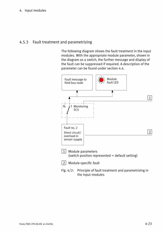
4. Input modules
4−23Festo P.BE−CPX−EA−EN en 0405b
4.5.3 Fault treatment and parametrizing
The following diagram shows the fault treatment in the inputmodules. With the appropriate module parameter, shown inthe diagram as a switch, the further message and display ofthe fault can be suppressed if required. A description of theparameter can be found under section 4.4.
Fault no. 2
Short circuit/overload insensor supply
Fault message tofield bus node
MonitoringSCS
Module fault LED
2
1
0 1
1 Module parameters (switch position represented = default setting)
2 Module−specific fault
Fig.�4/2: Principle of fault treatment and parametrizing inthe input modules
4. Input modules
4−24 Festo P.BE−CPX−EA−EN en 0405b

Output modules
5−1Festo P.BE−CPX−EA−EN en 0405b
Chapter 5
Type CPX−4DA
5. Output modules
5−2 Festo P.BE−CPX−EA−EN en 0405b
Contents
5. Output modules 5−1 . . . . . . . . . . . . . . . . . . . . . . . . . . . . . . . . . . . . . . . . . . . . . . . .
5.1 Function of the output modules 5−4 . . . . . . . . . . . . . . . . . . . . . . . . . . . . . . . . . . .
5.2 Fitting 5−4 . . . . . . . . . . . . . . . . . . . . . . . . . . . . . . . . . . . . . . . . . . . . . . . . . . . . . . . .
5.3 Installation 5−5 . . . . . . . . . . . . . . . . . . . . . . . . . . . . . . . . . . . . . . . . . . . . . . . . . . . .
5.3.1 Output module CPX−4DA 5−6 . . . . . . . . . . . . . . . . . . . . . . . . . . . . . . . . . .
5.4 Commissioning instructions 5−11 . . . . . . . . . . . . . . . . . . . . . . . . . . . . . . . . . . . . . .
5.5 Diagnosis 5−14 . . . . . . . . . . . . . . . . . . . . . . . . . . . . . . . . . . . . . . . . . . . . . . . . . . . . .
5.5.1 Fault messages of the output modules 5−15 . . . . . . . . . . . . . . . . . . . . . .
5.5.2 LED display 5−16 . . . . . . . . . . . . . . . . . . . . . . . . . . . . . . . . . . . . . . . . . . . .
5.5.3 Fault treatment and parametrizing 5−18 . . . . . . . . . . . . . . . . . . . . . . . . . .

5. Output modules
5−3Festo P.BE−CPX−EA−EN en 0405b
Contents of this chapter This chapter describes the CPX output modules.
The CPX output modules provide digital outputs in a CPXterminal and can be adapted to the specific application bymeans of various sub−bases.
Further information An overview of the modular structure of a CPX terminal, themodular connections as well as the display and connectingelements can be found in chapter 2.
Information on fitting the complete CPX terminal, the powersupply as well as general instructions on configuring andparametrizing can be found in the CPX system manual.
Information on the address assignment as well as on com�missioning can be found in the relevant manual for the fieldbus node or the function module.

5. Output modules
5−4 Festo P.BE−CPX−EA−EN en 0405b
5.1 Function of the output modules
Output modules provide digital outputs in the valve terminalfor connecting other current−consuming devices (valves,fuses, displays). At present the following type is available:
Type Description
CPX−4DA Provides 4 digital outputs (as per IEC�1131 type 2, 24�V,positive logic � PNP).
Tab.�5/1: Overview of output modules
5.2 Fitting
See section 3.3

5. Output modules
5−5Festo P.BE−CPX−EA−EN en 0405b
5.3 Installation
WarningSudden unexpected movements of the connected actua�tors and uncontrollable movements of loose tubing cancause injury to human beings and damage to property.
Before carrying out installation and/or maintenance work,switch off the following:
� the compressed air supply
� the operating and load voltage supplies.
In the following sections you will find the pin assignment of
the output modules for the various sub−bases.
Instructions on connecting the cables and plugs to the sub−bases can be found in section 3.2.3.
Power supply
The 24 V supply for the outputs is provided via the load volt�age outputs of the CPX terminal (Vout).
The power supply for the electronics of the output modules isprovided via the operating voltage supply for the electronics/sensors (Vel/sen).

5. Output modules
5−6 Festo P.BE−CPX−EA−EN en 0405b
5.3.1 Output module CPX−4DA
Pin assignment CPX−4DA with sub−baseCPX−AB−4−M12x2−5POL
O module type CPX−4DA with sub−base CPX−AB−4−M12x2−5POL
Sub−base Pin assignment X1, X2 LED Pin assignment X3, X4 LED
0
1
2
3
4DO
1
2
2
3
3
1
1
5
5
4
4
X1
X2
Socket X1:1: n.c.2: Ox+13: 0 Vout4: Ax5: FE
Socket X2:1: n.c.2: n.c.3: 0 Vout4: Ox+15: FE
1
0
1
1
2
2
3
3
1
1
5
5
4
4
X3
X4
Socket X3:1: n.c.2: Ox+33: 0 Vout4: Ox+25: FE
Socket X4:1: n.c.2: n.c.3: 0 Vout4: Ox+35: FE
3
2
3
Ox = Output xFE = Functional earthn.c. = Not connected
1 = Connected internally
Tab.�5/2: Pin assignment of O module type CPX−4DA with sub−baseCPX−AB−4−M12x2−5POL

5. Output modules
5−7Festo P.BE−CPX−EA−EN en 0405b
Pin assignment CPX−4DA with sub−baseCPX−AB−8−M8−3POL
Please noteSockets X1 to X8 on the sub−base are marked accordingly.The numbering of the sockets does not correspond to theoutput addresses.
O module type CPX−4DA with sub−base CPX−AB−8−M8−3POL
Sub−base Pin assignment X1 to X4 LED Pin assignment X5 to X8 LED
0
1
2
3
4DO
X�1
X�2
X�3
X�4
X�5
X�6
X�7
X�8
1
X14 1
3
X24 1
3
X34 1
3
X44 1
3
Socket X1:1: n.c.3: 0 Vout4: Ox
Socket X2:1: n.c.3: 0 Vout4: Ox+1
Socket X3:1: n.c.3: 0 Vout4: Ox+1
Socket X4:1: n.c.3: 0 Vout4: n.c.
0
1
1
1
X54 1
3
X64 1
3
X74 1
3
X84 1
3
Socket X5:1: n.c.3: 0 Vout4: Ox+2
Socket X6:1: n.c.3: 0 Vout4: Ox+3
Socket X7:1: n.c.3: 0 Vout4: Ox+3
Socket X8:1: n.c.3: 0 Vout4: n.c.
2
3
3
Ox = Output xFE = Functional earthn.c. = Not connected
1 = Connected internally
Tab.�5/3: Pin assignment of O module type CPX−4DA with sub−base CPX−AB−8−M8−3POL

5. Output modules
5−8 Festo P.BE−CPX−EA−EN en 0405b
Pin assignment CPX−4DA with sub−baseCPX−AB−8−KL−4POL
Please notePins X1 to X8 on the sub−base are marked accordingly. Thenumbering of the sockets does not correspond to the out�put addresses.
O module type CPX−4DA with sub−base CPX−AB−8−KL−4POL
Sub−base Pin assignment X1 to X4 LED Pin assignment X5 to X8 LED
0
1
2
3
4DO
X1
X2
X3
X4
X5
X6
X7
X8
.0
.1
.2
.3
.0
.1
.2
.3
.0
.1
.2
.3
.0
.1
.2
.3
X1
X2
X3
X4
.0
.1
.2
.3
.0
.1
.2
.3
.0
.1
.2
.3
.0
.1
.2
.3
1
X1.0: n.c.X1.1: 0 VoutX1.2: OxX1.3: FE
X2.0: n.c.X2.1: 0 VoutX2.2: Ox+1X2.3: FE
X3.0: n.c.X3.1: 0 VoutX3.2: Ox+1X3.3: FE
X4.0: n.c.X4.1: 0 VoutX4.2: n.c.X4.3: FE
0
1
1
X5
X6
X7
X8
.0
.1
.2
.3
.0
.1
.2
.3
.0
.1
.2
.3
.0
.1
.2
.3
1
X5.0: n.c.X5.1: 0 VoutX5.2: Ox+2X5.3: FE
X6.0: n.c.X6.1: 0 VoutX6.2: Ox+3X6.3: FE
X7.0: n.c.X7.1: 0 VoutX7.2: Ox+3X7.3: FE
X8.0: n.c.X8.1: 0 VoutX8.2: n.c.X8.3: FE
2
3
3
Ox = Output xFE = Functional earthn.c. = Not connected
1 = Connected internally
Tab.�5/4: Pin assignment of O module type CPX−4DA with sub−base CPX−AB−8−KL−4POL

5. Output modules
5−9Festo P.BE−CPX−EA−EN en 0405b
Pin assignment CPX−4DA with sub−baseCPX−AB−1−SUB−BU−25POL
O module type CPX−4DA with sub−base CPX−AB−1−SUB−BU−25POL
Sub−base Pin assignment LED Pin assignment LED
0
1
2
3
4DO
1
2
3
4
5
6
7
8
9
10
11
12
13
14
15
16
17
18
19
20
21
22
23
24
25
1: Ox2: Ox+13: Ox+14: n.c.5: n.c.6: 0 Vout7: n.c.8: 0 Vout9: n.c.10: n.c.11: 0 Vout12: 0 Vout13: FE
011
14: Ox+215: Ox+316: Ox+317: n.c.18: n.c.19: n.c.20: n.c.21: n.c.22: 0 Vout23: 0 Vout24: 0 Vout25: FEHousing: FE
233
Ox = Output xFE = Functional earth0 V = 0 V loadn.c. = Not connected
Tab.�5/5: Pin assignment of O module type CPX−4DA with sub−baseCPX−AB−1−SUB−BU−25POL

5. Output modules
5−10 Festo P.BE−CPX−EA−EN en 0405b
Pin assignment CPX−4DA with sub−baseCPX−AB−4−HARX2−4POL
O module type CPX−4DA with sub−base CPX−AB−4−HARX2−4POL
Sub−base Pin assignment X1, X2 LED Pin assignment X3, X4 LED
0
1
2
3
4DO
1
23
14
X1
X22 3
1 4
Socket X1:1: n.c.2: Ox+13: 0 Vout4: Ax
Socket X2:1: n.c.2: n.c.3: 0 Vout4: Ox+1
1
0
1
1
23
14
X3
X42 3
1 4
Socket X3:1: n.c.2: Ox+33: 0 Vout4: Ox+2
Socket X4:1: n.c.2: n.c.3: 0 Vout4: Ox+3
3
2
3
Ox = Output xFE = Functional earthn.c. = Not connected
1 = Connected internally
Tab.�5/6: Pin assignment of O module type CPX−4DA with sub−baseCPX−AB−4−HARX2−4POL

5. Output modules
5−11Festo P.BE−CPX−EA−EN en 0405b
5.4 Commissioning instructions
The reaction of the I/O modules can be parametrized. Thefollowing table provides an overview of the parameters.
Further information on parametrizing can be found in thesystem manual and in the manual for the field bus node.
Parameters of output modules type CPX−4DA
Module parameters: Monitoring the CPX module
Function no. 4828 + m * 64 + 0 m = module number (0 ... 47)
Description Monitoring of the possible faults can be activated or deactivated (suppressed)for each module independently. Active monitoring causes the following: The fault is:� sent to the CPX field bus node� shown on the module common fault LED.
Bit12
MonitoringDescriptionShort circuit/overload at outputs (SCO)Undervoltage at outputs (Vout)
[Monitor]
[Monitor SCO][Monitor Vout]
Values 1 = active (presetting)0 = inactive
[Active][Inactive]
Note Monitoring can also be set for the complete CPX terminal (see �Monitoringsystem parameters").
Tab.�5/7: Monitoring the CPX module

5. Output modules
5−12 Festo P.BE−CPX−EA−EN en 0405b
Module parameters: Behaviour after short circuit/overload
Function no. 4828 + m * 64 + 1 m = module number (0 ... 47)
Description Defines whether the voltage is to remain switched off after a short circuit at theoutputs, or whether it is to be switched on again automatically.
Bit1
Behaviour after short circuit/overloadDescriptionShort circuit/overload at outputs (SCO)
[Behaviour after]
[Behaviour after SCO]
Values 0 = Vout remains switched off (presetting)1 = Vout switch on again
[Leave switched off ][Resume]
Note With the setting �Vout remains switched off", Reset/Set the relevant output isrequired for switching on the power supply again. Check to ascertain the settingwhich is required for reliable operation of your system.Detailed description under Diagnosis, Tab.�5/12.
Tab.�5/8: Behaviour after short circuit/overload
Module parameters: Fail safe channel x
Function no. Access to these module parameters is made via protocol−specific functions (see manual for field bus node).
Description Fault mode channel x: Hold last stateFault state (presetting)
Fault state channel x: Set outputReset output (presetting)
Note With the so−called Fail safe parametrizing, you can defines the signal statuswhich outputs should assume in the event of field bus communication faults(see also CPX system manual).
Tab.�5/9: Fail safe channel x (channel−specific)

5. Output modules
5−13Festo P.BE−CPX−EA−EN en 0405b
Module parameters: Idle mode channel x
Function no. Access to these module parameters is made via protocol−specific functions (see manual for field bus node).
Description Only relevant with certain field bus protocols.Idle mode channel x: Hold last state
Idle state (presetting)Fault state channel x: Set output
Reset output (presetting)
Note With the so−called Idle mode parametrizing, you can define the signal statuswhich outputs should assume when they change to the idle state (see also CPXsystem manual). This parameter is not available with all field bus protocols.
Tab.�5/10: Idle mode channel x (channel−specific)
Module parameters: Force channel x
Function no. Access to these module parameters is made via protocol−specific functions (see manual for field bus node).
Description Force mode outputs channel x: Disabled (presetting)Force state
Force state outputs channel x: Set signalReset signal (presetting)
Note The function Force enables the manipulation of signal states disconnected fromactual operating states (see also CPX system manual).
Tab.�5/11: Force channel x (channel−specific)
5. Output modules
5−14 Festo P.BE−CPX−EA−EN en 0405b
5.5 Diagnosis
Specific faults of the output modules are registered or sup�pressed, depending on the module parametrizing.
The faults are shown on the spot by means of the fault LEDsand can be evaluated, if necessary, with the handheld (MMI).
Depending on the module parametrizing, the faults are regis�tered with the field bus node and can be evaluated there ac�cording to the field bus protocol used.

5. Output modules
5−15Festo P.BE−CPX−EA−EN en 0405b
5.5.1 Fault messages of the output modules
An output module can register the following standard faults:
Fault number Description Fault treatment
2 Short circuit/overload faultshort circuit/overload at output
The reaction depends on theparametrizing �Behaviour aftershort circuit/overload at outputs(SCO)":� Setting �Vout remains
switched off" (default): The output will be switched off
� Setting �Voutswitch on again":The output current will belimited to approx. 250�mA.
1. Check actuators, eliminate short circuit/overload (number of faulty channel: seeLED display or module diagnostic data).
2. Depending on the parametrizing�Behaviour after short circuit/overload atoutputs (SCO)":
· Set output to 0, then to 1 again, ormodify the parameter �Behaviour aftershort circuit/overload at outputs (SCO)"to �Vout switch on again".
· If the output current is less than 400�mA:The voltage will be switched on againautomatically when the short circuit hasbeen eliminated. If the output current is grater than400�mA: Set the output to 0, then to 1 again.
5 Fault in load voltage for outputsLoad voltage at outputs (Vout)not applied or too low. 1)
· Check load voltage
1) Tolerance range of the load voltage supply Vout see Technical Specifications in the Appendix.
Tab.�5/12: Fault messages of the output modules

5. Output modules
5−16 Festo P.BE−CPX−EA−EN en 0405b
5.5.2 LED display
Various LEDs are available under the transparent cover of themodule for diagnosing the output modules.
1 Status LEDs (yellow) �assignment to theoutputs see pinassignment of themodule
2 Channel−related faultLEDs (red)
3 Fault LED (red) (module fault)
0
1
2
3
4DO
1 2
CPX−4DA
3
Fig.�5/1: LED display of the output modules
Status LEDs
For every output there is a yellow status LED. This shows thestatus of the signal at the relevant output. The LEDs indicatethe following:
Status LED(yellow)
Sequence Status
LED lights up
ON
OFF
Logical 1(output supplies 1−signal)
LED is out
ON
OFFLogical 0(output supplies 0−signal)
Tab.�5/13: Status LEDs of the output modules
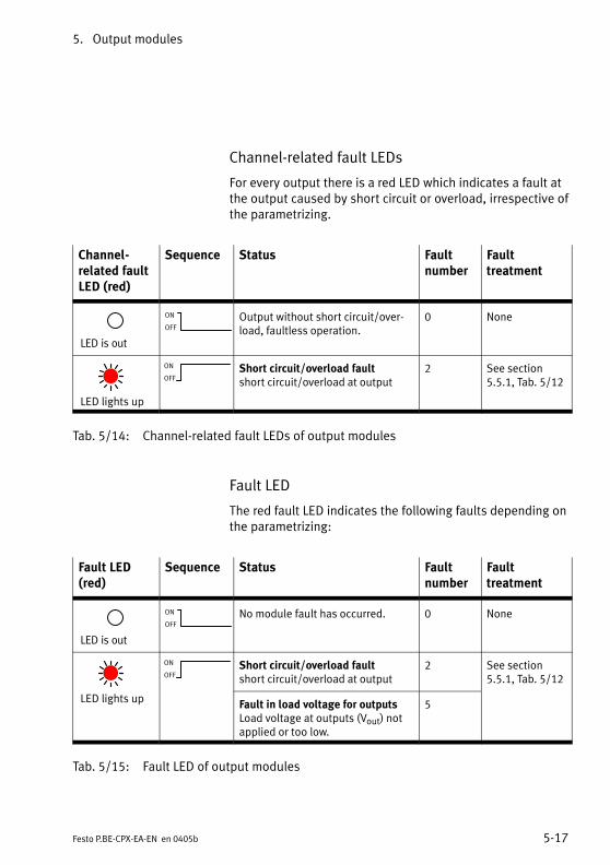
5. Output modules
5−17Festo P.BE−CPX−EA−EN en 0405b
Channel−related fault LEDs
For every output there is a red LED which indicates a fault atthe output caused by short circuit or overload, irrespective ofthe parametrizing.
Channel−related faultLED (red)
Sequence Status Faultnumber
Faulttreatment
LED is out
ON
OFF
Output without short circuit/over�load, faultless operation.
0 None
LED lights up
ON
OFFShort circuit/overload faultshort circuit/overload at output
2 See section5.5.1, Tab.�5/12
Tab.�5/14: Channel−related fault LEDs of output modules
Fault LED
The red fault LED indicates the following faults depending onthe parametrizing:
Fault LED(red)
Sequence Status Faultnumber
Faulttreatment
LED is out
ON
OFF
No module fault has occurred. 0 None
ON
OFFShort circuit/overload faultshort circuit/overload at output
2 See section5.5.1, Tab.�5/12
LED lights upFault in load voltage for outputsLoad voltage at outputs (Vout) notapplied or too low.
5
Tab.�5/15: Fault LED of output modules

5. Output modules
5−18 Festo P.BE−CPX−EA−EN en 0405b
5.5.3 Fault treatment and parametrizing
The following diagram shows the fault treatment in the out�put modules. With the appropriate module parameters,shown in the diagram as a switch, the further message anddisplay of the faults can be suppressed if required. A descrip�tion of the parameters can be found under section 5.4.
2
Fault message tofield bus node
...
Fault no. 5
Fault in loadvoltage foroutputs
Fault no. 2
Short circuit/overload atoutput 0
Fault no. 2
Short circuit/overload atoutput 3
MonitoringVout
MonitoringSCO
Module faultLED
3
1
Channel−relatedfault LEDchannel 3
Channel−relatedfault LEDchannel 0
...
0 1 0 1
1 Module parameter (switch position represented = default setting)
2 Module−specific fault
3 Channel−specific fault
Fig.�5/2: Principle of fault treatment and parametrizing in the output modules

Multi I/O modules
6−1Festo P.BE−CPX−EA−EN en 0405b
Chapter 6
Type CPX−8DE−8DA

6. Multi I/O modules
6−2 Festo P.BE−CPX−EA−EN en 0405b
Contents
6. Multi I/O modules 6−1 . . . . . . . . . . . . . . . . . . . . . . . . . . . . . . . . . . . . . . . . . . . . . .
6.1 Function of the multi I/O modules 6−4 . . . . . . . . . . . . . . . . . . . . . . . . . . . . . . . . .
6.2 Fitting 6−4 . . . . . . . . . . . . . . . . . . . . . . . . . . . . . . . . . . . . . . . . . . . . . . . . . . . . . . . .
6.3 Installation 6−5 . . . . . . . . . . . . . . . . . . . . . . . . . . . . . . . . . . . . . . . . . . . . . . . . . . . .
6.3.1 Multi I/O module CPX−8DE−8DA 6−6 . . . . . . . . . . . . . . . . . . . . . . . . . . . .
6.4 Commissioning instructions 6−10 . . . . . . . . . . . . . . . . . . . . . . . . . . . . . . . . . . . . . .
6.5 Diagnosis 6−16 . . . . . . . . . . . . . . . . . . . . . . . . . . . . . . . . . . . . . . . . . . . . . . . . . . . . .
6.5.1 Fault messages of the multi I/O modules 6−16 . . . . . . . . . . . . . . . . . . . .
6.5.2 LED display 6−18 . . . . . . . . . . . . . . . . . . . . . . . . . . . . . . . . . . . . . . . . . . . .
6.5.3 Fault treatment and parametrizing 6−20 . . . . . . . . . . . . . . . . . . . . . . . . . .

6. Multi I/O modules
6−3Festo P.BE−CPX−EA−EN en 0405b
Contents of this chapter This chapter describes the CPX multi I/O modules.
The CPX multi I/O modules provide digital inputs and outputsin a CPX terminal and can be adapted to the specific applica�tion by means of various sub−bases.
Further information An overview of the modular structure of a CPX terminal, themodular connections as well as the display and connectingelements can be found in chapter 2.
Information on fitting the complete CPX terminal, the powersupply as well as general instructions on configuring andparametrizing can be found in the CPX system manual.
Information on the address assignment as well as on com�missioning can be found in the relevant manual for the fieldbus node or the function module.

6. Multi I/O modules
6−4 Festo P.BE−CPX−EA−EN en 0405b
6.1 Function of the multi I/O modules
Multi I/O modules provide digital inputs in the valve terminalfor connecting sensors as well as digital outputs for connect�ing electric actuators and other current−consuming devices(valves, fuses, displays). At present the following type isavailable:
Type Description
CPX−8DE−8DA Provides 8 digital inputs (as perIEC 1131 type 2, 24�V, positivelogic � PNP) as well as 8 digitaloutputs (as per IEC�1131 type 2,24�V, positive logic � PNP).
Tab.�6/1: Overview of multi I/O modules
6.2 Fitting
See section 3.3

6. Multi I/O modules
6−5Festo P.BE−CPX−EA−EN en 0405b
6.3 Installation
WarningSudden unexpected movements of the connected actua�tors and uncontrollable movements of loose tubing cancause injury to human beings and damage to property.
Before carrying out installation and/or maintenance work,switch off the following:
� the compressed air supply
� the operating and load voltage supplies.
In the following sections you will find the pin assignment of
the multi I/O modules for the various sub−bases.
Instructions on connecting the cables and plugs to the sub−bases can be found in section 3.2.3.
Power supply
The 24 V supply for the outputs is provided via the load volt�age outputs of the CPX terminal (Vout).
The 24 V sensor supply for the inputs as well as the powersupply for the electronics of the multi I/O modules is pro�vided via the operating voltage supply for the electronics/sensors (Vel/sen).

6. Multi I/O modules
6−6 Festo P.BE−CPX−EA−EN en 0405b
6.3.1 Multi I/O module CPX−8DE−8DA
Pin assignment CPX−8DE−8DA with sub−baseCPX−AB−8−KL−4POL
Multi I/O module type CPX−8DE−8DA with sub−base CPX−AB−8−KL−4POL
Sub−base Pin assignment X1 to X4 LED Pin assignment X5 to X8 LED
0
1
2
3
8DI
4
5
6
7
X1
X2
X3
X4
X5
X6
X7
X8
.0
.1
.2
.3
.0
.1
.2
.3
.0
.1
.2
.3
.0
.1
.2
.3
0
1
2
3
4
5
6
7
8DO
X1
X2
X3
X4
.0
.1
.2
.3
.0
.1
.2
.3
.0
.1
.2
.3
.0
.1
.2
.3
X1.0: 24 V senX1.1: 0 V senX1.2: IxX1.3: FE
X2.0: Ix+4X2.1: Ix+5X2.2: Ix+1X2.3: FE
X3.0: 24 V senX3.1: 0 V senX3.2: Ix+2X3.3: FE
X4.0: Ix+6X4.1: Ix+7X4.2: Ix+3X4.3: FE
0 (I)
4 (I)5 (I)1 (I)
2 (I)
6 (I)7 (I)3 (I)
X5
X6
X7
X8
.0
.1
.2
.3
.0
.1
.2
.3
.0
.1
.2
.3
.0
.1
.2
.3
X5.0: Ox+4X5.1: 0 VoutX5.2: OxX5.3: FE
X6.0: Ox+5X6.1: 0 VoutX6.2: Ox+1X6.3: FE
X7.0: Ox+6X7.1: 0 VoutX7.2: Ox+2X7.3: FE
X8.0: Ox+7X8.1: 0 VoutX8.2: Ox+3X8.3: FE
4 (O)
0 (O)
5 (O)
1 (O)
6 (O)
2 (O)
7 (O)
3 (O)
Ix = Input xOx = Output xFE = Functional earth
Tab.�6/2: Pin assignment of multi I/O module type CPX−8DE−8DA with sub−baseCPX−AB−8−KL−4POL

6. Multi I/O modules
6−7Festo P.BE−CPX−EA−EN en 0405b
Pin assignment CPX−8DE−8DA with sub−baseCPX−AB−1−SUB−BU−25POL
Multi I/O module type CPX−8DE−8DA with sub−base CPX−AB−1−SUB−BU−25POL
Sub−base Pin assignment LED Pin assignment LED
0
1
2
3
8DI
4
5
6
7
0
1
2
3
4
5
6
7
8DO
1
2
3
4
5
6
7
8
9
10
11
12
13
14
15
16
17
18
19
20
21
22
23
24
25
1: Ix2: Ix+13: Ix+24: Ix+35: Ix+46: Ix+57: Ix+68: Ix+79: 24 Vsen10: 24 Vsen11: 0 Vsen12: 0 Vsen13: FE
0 (I)1 (I)2 (I)3 (I)4 (I)5 (I)6 (I)7 (I)
14: Ox15: Ox+116: Ox+217: Ox+318: Ox+419: Ox+520: Ox+621: Ox+722: 0 Vout23: 0 Vout24: 0 Vout25: FEHousing: FE
0 (O)1 (O)2 (O)3 (O)4 (O)5 (O)6 (O)7 (O)
Ix = Input xOx = Output xFE = Functional earth
Tab.�6/3: Pin assignment of multi I/O module type CPX−8DE−8DA with sub−baseCPX−AB−1−SUB−BU−25POL

6. Multi I/O modules
6−8 Festo P.BE−CPX−EA−EN en 0405b
Pin assignment CPX−8DE−8DA with sub−baseCPX−AB−4−M12−8POL
Please noteWith multi I/O module CPX−8DE−8DA with sub−base CPX−AB−4−M12−8POL, the inputs Ix+4 and Ix+6 are provided onthe sockets X1 and X3 or X2 and X4 (connected internally).
Multi I/O module type CPX−8DE−8DA with sub−base CPX−AB−4−M12−8POL
Sub−base Pin assignment X1, X2 LED Pin assignment X3, X4 LED
0
1
2
3
8DI
4
5
6
7
0
1
2
3
4
5
6
7
8DO
2
3
1
5
4
X2
8
6
7
2
3
1
5
4
X1
8
6
7
Socket X1:1: 24 Vsen2: Ix3: Ix+14: 0 Vsen5: Ox6: Ox+17: Ix+48: 0 Vout
Socket X2:1: 24 Vsen2: Ix+23: Ix+34: 0 Vsen5: Ox+26: Ox+37: Ix+68: 0 Vout
0 (I)1 (I)
0 (O)1 (O)4 (I)
2 (I)3 (I)
2 (O)3 (O)6 (I)
2
3
1
5
4
X4
8
6
7
2
3
1
5
4
X3
8
6
7
Socket X3:1: 24 Vsen2: Ix+43: Ix+54: 0 Vsen5: Ox+46: Ox+57: n.c.8: 0 Vout
Socket X4:1: 24 Vsen2: Ix+63: Ix+74: 0 Vsen5: Ox+66: Ox+77: n.c.8: 0 Vout
4 (I)5 (I)
4 (O)5 (O)
6 (I)7 (I)
6 (O)7 (O)
Ix = Input xOx = Output xn.c. = Not connected
Tab.�6/4: Pin assignment of multi I/O module type CPX−8DE−8DA with sub−baseCPX−AB−4−M12x2−5POL

6. Multi I/O modules
6−9Festo P.BE−CPX−EA−EN en 0405b
Sockets X1 to X4 have been designed for connecting cylinder−valve combinations type DNCV with connecting cable typeKM12−8GD8GS−2−PU.
Please noteInputs Ix+4 and Ix+6 are provided both at pin 7 of socketsX1 and X2, as well as at pin 2 of sockets X3 and X4.
The cylinder−valve combination type DNCV with diagnosticmodule and activated diagnostic output supplies an in�verted diagnostic signal (1−signal = no fault) at pin�7.
If, therefore, the cylinder−valve combination type DNCVwith diagnostic module and activated diagnostic output isconnected to sockets X1 and X2, pin 2 on sockets X3 andX4 cannot be used.

6. Multi I/O modules
6−10 Festo P.BE−CPX−EA−EN en 0405b
6.4 Commissioning instructions
The reaction of the I/O modules can be parametrized. Thefollowing table provides an overview of the parameters.
Further information on parametrizing can be found in thesystem manual and in the manual for the field bus node.
Parameters of the multi I/O module CPX−8DE−8DA
Module parameters: Monitoring the CPX module
Function no. 4828 + m * 64 + 0 m = module number (0 ... 47)
Description Monitoring of the possible faults can be activated or deactivated (suppressed)for each module independently. Active monitoring causes the following: The fault is:� sent to the CPX field bus node� shown on the module common fault LED.
Bit012
MonitoringDescriptionShort circuit/overload in sensor supply (SCS)Short circuit/overload at outputs (SCO)Undervoltage at outputs (Vout)
[Monitor]
[Monitor SCS][Monitor SCO][Monitor Vout]
Values 1 = active (presetting)0 = inactive
[Active][Inactive]
Note Monitoring can also be set for the complete CPX terminal (see �Monitoringsystem parameters").
Tab.�6/5: Monitoring the CPX module

6. Multi I/O modules
6−11Festo P.BE−CPX−EA−EN en 0405b
Module parameters: Behaviour after short circuit/overload
Function no. 4828 + m * 64 + 1 m = module number (0 ... 47)
Description Defines whether the voltage is to remain switched off after a short circuit in thesensor supply or at the outputs, or whether it is to be switched on again auto�matically.
Bit01
Behaviour after short circuit/overloadDescriptionShort circuit/overload in sensor supply (SCS)Short circuit/overload at outputs (SCO)
[Behaviour after]
[Behaviour after SCS][Behaviour after SCO]
Values 0 = Vsen/Vout remains switched off1 = Vsen/Vout switch on againPresetting: bit 0: Vsen/Vout switch on again;
bit 1: Vsen/Vout remains switched off
[Leave switched off ][Resume]
Note With the setting �Vsen/out remains switched off", Power Off/On or Reset/Set therelevant output is required for switching on the power supply again. Check toascertain the setting which is required for reliable operation of your system.Detailed description under Diagnosis, Tab.�6/14.
Tab.�6/6: Behaviour after short circuit/overload

6. Multi I/O modules
6−12 Festo P.BE−CPX−EA−EN en 0405b
Module parameters: Input debounce time
Function no. 4828 + m * 64 + 1 m = module number (0 ... 47)
Description Defines when a change of edge of the sensor signal on this module is to beaccepted as a logical input signal.
Bit Bit 4, 5
ValuesBit 5 4
0 00 11 01 1
Input debounce timeDescription0.1 ms3 ms (presetting)10 ms20 ms
[Debounce time]
Note Input debounce times are specified in order to eliminate interfering changes ofsignal edge during switching procedures (input signal bounces). The settingapplies to all inputs on the module.Further information on this parameter can be found in the CPX system manual.
Tab.�6/7: Input debounce time
6. Multi I/O modules
6−13Festo P.BE−CPX−EA−EN en 0405b
Module parameters: Signal extension time
Function no. 4828 + m * 64 + 1 m = module number (0 ... 47)
Description Defines the signal extension time for the relevant I module. Signal statesaccepted as logical input signals remain valid at least until the defined signalextension time (minimum signal duration) has expired. Changes of edge duringthe extension time will be ignored.
Bit Bit 6, 7
ValuesBit 7 6
0 00 11 01 1
Signal extension timeDescription0.5 ms15 ms (presetting)50 ms100 ms
[Signal extension]
Note Due to long cycle times of a higher−order controller, there is a danger of shortsignals not being �recognized". In order that such signals are also considered inthe control sequence, a signal extension time can be specified (see CPX systemmanual). The signal extension time can be activated channel by channel (seechannel−specific module parameters).
Tab.�6/8: Signal extension time
Module parameters: Signal extension channel x
Function no. 4828 + m * 64 + 6 m = module number (0 ... 47)
Description Defines whether the signal extension for the appropriate input channel isenabled or disabled.
Bit Bit 0 ... 7 (channel 0 ... 7)
Values Signal extension input channel ...0 = disabled (presetting)1 = enabled
[Signal extension Inp Ch ...][Disabled][Enabled]
Note The signal extension time can be defined separately for each module (see function no. 4828 + n; n = m * 64 + 1).
Tab.�6/9: Signal extension channel x (channel−specific)

6. Multi I/O modules
6−14 Festo P.BE−CPX−EA−EN en 0405b
Module parameters: Fail safe channel x
Function no. Access to these module parameters is made via protocol−specific functions (see manual for field bus node).
Description Fault mode channel x: Hold last stateFault state (presetting)
Fault state channel x: Set outputReset signal (presetting)
Note With the so−called Fail safe parametrizing, you can define the signal status whichoutputs should assume in the event of field bus communication faults (see alsoCPX system manual).
Tab.�6/10: Fail safe channel x (channel−specific)
Module parameters: Idle mode channel x
Function no. Access to these module parameters is made via protocol−specific functions (see manual for field bus node).
Description Only relevant with certain field bus protocols.Idle mode channel x: Hold last state
Idle state (presetting)Idle state channel x: Set output
Reset output (presetting)
Note With the so−called Idle mode parametrizing, you can define the signal statuswhich outputs should assume when they change to the idle state (see also CPXsystem manual). This parameter is not available with all field bus protocols.
Tab.�6/11: Idle mode channel x (channel−specific)

6. Multi I/O modules
6−15Festo P.BE−CPX−EA−EN en 0405b
Module parameters: Force channel x
Function no. Access to these module parameters is made via protocol−specific functions (see manual for field bus node).
Description Force mode inputs channel x: Disabled (presetting)Force state
Force state inputs channel x: Set signalReset signal (presetting)
Force mode outputs channel x: Disabled (presetting)Force state
Force state outputs channel x: Set signalReset signal (presetting)
Note The function Force enables the manipulation of signal states disconnected fromactual operating states (see also CPX system manual).
Tab.�6/12: Force channel x (channel−specific)

6. Multi I/O modules
6−16 Festo P.BE−CPX−EA−EN en 0405b
6.5 Diagnosis
Specific faults of the multi I/O modules are registered or sup�pressed, depending on the module parametrizing.
The faults are shown on the spot by means of the fault LEDsand can be evaluated, if necessary, with the handheld (MMI).
Depending on the module parametrizing, the faults are regis�tered with the field bus node and can be evaluated there ac�cording to the field bus protocol used.
6.5.1 Fault messages of the multi I/O modules
A multi I/O module can register the following standard faults:
Fault number Description Fault treatment
2 Short circuit/overload fault� Short circuit/overload in
sensor supply (Vel/sen).
or (see continued)
1. Eliminate short circuit/overload, if necessarycheck connected sensors.
2. Depending on the parametrizing �Shortcircuit/overload in sensor supply (SCS)":· Setting �Vsen switch on again":
The sensor supply voltage will be switchedon again automatically when the shortcircuit has been eliminated.
· Setting �Vsen remains switched off":� Power Off/On necessary or � parameter �Modify behaviour after
short circuit/overload in sensor supply (SCS)" to �V�sen switch on again".
Tab.�6/13: Fault messages of the multi I/O modules � part 1

6. Multi I/O modules
6−17Festo P.BE−CPX−EA−EN en 0405b
Fault number Description Fault treatment
2 (continued) Short circuit/overload faultShort circuit/overload at output
The reaction depends on theparametrizing �Behaviour aftershort circuit/overload at outputs(SCO)":� Setting �Vsen remains
switched off" (default): The output will be switched off
� Setting �Vsen switch onagain": The output current will belimited to approx. 250�mA.
1. Check actuators, eliminate short circuit/overload (number of faulty channel: seemodule diagnostic data).
2. Depending on the parametrizing �Behaviourafter short circuit/overload at outputs(SCO)":
· Set output to 0, then to 1 again, or mod�ify the parameter �Behaviour after shortcircuit/overload at outputs (SCO)" to�Vout switch on again".
· If the output current is less than 400�mA:The voltage will be switched on againautomatically when the short circuit hasbeen eliminated. If the output current is grater than400�mA: Set the output to 0, then to 1 again.
5 Fault at load voltage outputsLoad voltage at outputs (Vout)not applied or too low. 1)
· Check load voltage
1) Tolerance range of the load voltage supply Vout see Technical specifications in the Appendix.
Tab.�6/14: Fault messages of the multi I/O modules � part 2
Please noteNote when using the multi I/O modules:
� In the event of a short circuit, all sensor supplies will beswitched off together.
� Providing it is not parametrized otherwise, the sensorsupply voltage will be switched on again automaticallywhen the short circuit has been eliminated.
6. Multi I/O modules
6−18 Festo P.BE−CPX−EA−EN en 0405b
6.5.2 LED display
Various LEDs are available under the transparent cover of themodule for diagnosing the multi I/O modules.
1 Status LEDs (green) �assignment to the inputs see pin assign�ment of the module
2 Status LEDs (yellow) �assignment to theoutputs see pinassignment of themodule
3 Fault LED (red) (module fault)
0
1
2
3
8DI
4
5
6
7
1 2
CPX−8DE−8DA
0
1
2
3
4
5
6
7
8DO
3
Fig.�6/1: LED display of the multi I/O modules
Status LEDs (green)
For every input there is a green status LED. This shows thestatus of the signal at the relevant input. The LEDs indicatethe following:
Status LED(green)
Sequence Status
LED lights up
ON
OFF
Logical 1 (signal present)
LED is out
ON
OFF
Logical 0 (no signal)
Tab.�6/15: Status LEDs of the inputs of the multi I/Omodules

6. Multi I/O modules
6−19Festo P.BE−CPX−EA−EN en 0405b
Status LEDs (yellow)
For every output there is a yellow status LED. This shows thestatus of the signal at the relevant output. The LEDs indicatethe following:
Status LED(yellow)
Sequence Status
LED lights up
ON
OFF
Logical 1(output supplies 1−signal)
LED is out
ON
OFFLogical 0(output supplies 0−signal)
Tab.�6/16: Status LEDs of the outputs of the multi I/Omodules
Fault LED
The red fault LED shows the module fault �Short circuit/over�load in sensor supply" and faults which refer to individualoutputs, e.g. due to short circuit or overload.
Fault LED(red)
Sequence Status Faultnumber
Faulttreatment
LED is out
ON
OFF
Faultless operation 0 None
LED lights up
ON
OFFShort circuit/overload fault� short circuit/overload in sensor
supply (Vel/sen) or� short circuit/overload at output
2 See section6.5.1, Tab.�6/13and Tab.�6/14.
Fault in load voltage for outputsLoad voltage at outputs (Vout) notapplied or too low.
5
Tab.�6/17: Fault LED of multi I/O modules

6. Multi I/O modules
6−20 Festo P.BE−CPX−EA−EN en 0405b
6.5.3 Fault treatment and parametrizing
The following diagram shows the fault treatment in the multiI/O modules. With the appropriate module parameters,shown in the diagram as a switch, the further message anddisplay of the fault can be suppressed if required. A descrip�tion of the parameters can be found under section 6.4.
2
Fault no. 2
Short circuit/overload insensor supply
Fault message tofield bus node
...
Fault no. 5
Fault in loadvoltage
Fault no. 2
Short circuit/overload atoutput 0
Fault no. 2
Short circuit/overload atoutput 7
MonitoringSCS
MonitoringVout
MonitoringSCO
Module faultLED
3
1
0 1 0 1 0 1
1 Module parameter (switch position represented = default setting)
2 Module−specific fault
3 Channel−specific fault
Fig.�6/2: Principle of fault treatment and parametrizing in the multi I/O modules

Technical appendix
A−1Festo P.BE−CPX−EA−EN en 0405b
Appendix A

A. Technical appendix
A−2 Festo P.BE−CPX−EA−EN en 0405b
Contents
A. Technical appendix A−1 . . . . . . . . . . . . . . . . . . . . . . . . . . . . . . . . . . . . . . . . . . . . .
A.1 Technical specifications of the pneumatic interfaces A−3 . . . . . . . . . . . . . . . . . . .
A.2 Technical specifications of the MPA electronic modules A−4 . . . . . . . . . . . . . . . .
A.3 Technical specifications of the input modules A−6 . . . . . . . . . . . . . . . . . . . . . . . .
A.4 Technical specifications of the output modules A−7 . . . . . . . . . . . . . . . . . . . . . . .
A.5 Technical specifications of the multi I/O modules A−8 . . . . . . . . . . . . . . . . . . . . .
A.6 Technical specifications of the sub−bases A−10 . . . . . . . . . . . . . . . . . . . . . . . . . . . .
A.7 Internal structure of the CPX modules A−12 . . . . . . . . . . . . . . . . . . . . . . . . . . . . . .
A.8 Examples of circuitry A−15 . . . . . . . . . . . . . . . . . . . . . . . . . . . . . . . . . . . . . . . . . . . .
A.8.1 Examples of circuitry (PNP inputs) A−15 . . . . . . . . . . . . . . . . . . . . . . . . . .
A.8.2 Examples of circuitry (PNP outputs) A−15 . . . . . . . . . . . . . . . . . . . . . . . . .
A.8.3 Example of circuitry with DUO cable A−16 . . . . . . . . . . . . . . . . . . . . . . . .
A.8.4 Example of circuitry with DNCV A−17 . . . . . . . . . . . . . . . . . . . . . . . . . . . .
A.9 Accessories A−18 . . . . . . . . . . . . . . . . . . . . . . . . . . . . . . . . . . . . . . . . . . . . . . . . . . . .

A. Technical appendix
A−3Festo P.BE−CPX−EA−EN en 0405b
A.1 Technical specifications of the pneumatic interfaces
Technical specifications CPX−GP−03−4.0 CPX−GP−CPA−...
General technical specifications of theCPX terminal
See CPX system manual
Protection class as per EN 60529 IP65, in fitted state
Operating voltage supply for electronics/sensors (Vel/sen)� Rated voltage� Internal current consumption at 24 V
(internal electronics)
24 V DC ± 25 %Typ. 15 mA
Load voltage supply for valves (Vval)� Rated voltage� Internal current consumption at 24 V
(internal electronics, without valves)� Diagnostic message undervoltage Vval
(monitoring Vval, load voltage outsidefunction range)
24 V DC ± 10 %Typ. 30 mA
� 21.6 ... 21.5 V
24 V DC +10 %/−15 %Typ. 30 mA
� 19.8 ... 19.6 V
Digital outputs (valve solenoid coils)� Rated load voltage� Intended for connecting pneumatics� Short circuit protection at valve output
� Monitoring wire fracture (open load)
Max. 26 outputsVvalMidi/Maxi (type 03)Yes (electronic),Response threshold > 1.0 ANo
Max. 22 outputsVvalCPA (type 12)Yes (electronic),Response threshold > 1.0 ACan be parametrized
Isolation Tested with 500 V DC
Electrical isolation ...� between the channels (valve solenoid
coils)� between operating voltage supply for
the electronics/sensors (Vel/sen) andload voltage for valves (Vval)
None
If power is supplied via manifold sub−base type:� CPX−GE−EV−S: None� CPX−GE−EV−Z: None� CPX−GE−EV−V: Yes
Module code [type code] (CPX−specific)Module identifier (handheld)
67TYP3
66CPA10/14

A. Technical appendix
A−4 Festo P.BE−CPX−EA−EN en 0405b
A.2 Technical specifications of the MPA electronic modules
Technical specifications VMPA1−FB−EMG−8 VMPA1−FB−EMS−8
General technical specifications of theCPX terminal
See CPX system manual
Protection class as per EN 60529 IP65, in fitted state (MPA pneumatic module fitted completely)
Operating voltage supply forelectronics/sensors (Vel/sen)� Rated voltage� Internal current consumption at 24 V
(internal electronics, all outputs (valvesolenoid coils) 0−signal)
24 V DC ± 25 %Typ. 13 ... 20 mA
Load voltage supply for valves (Vval)� Rated voltage� Internal current consumption at 24 V
(internal electronics, without valves)� Diagnostic message undervoltage Vval
(monitoring Vval, load voltage outsidefunction range)
24 V DC ± 25 %Typ. 25 mA
� 17.5 ... 16.0 V
24 V DC ± 25 %Typ. 8 mA
� 17.5 ... 16.0 V
Digital outputs (valve solenoid coils)� Rated load voltage� Permitted valve plates� Short circuit protection at valve output� Current consumption per solenoid coil:
� Rated pick−up current� Rated current with current reduction
8 outputsVvalType VMPA1−M1H−... (or reserve plate type VMPA1−RP)Yes (electronic)
65 mA25 mA
Isolation Tested with 500 V DC
Electrical isolation ...� between the channels (valve solenoid
coils)� between the operating voltage supply
for the electronics/sensors (Vel/sen)and the load voltage for the valves(Vval)
None
If power is supplied viamanifold sub−base type:� CPX−GE−EV−S: None� CPX−GE−EV−Z: None� CPX−GE−EV−V: Yes
None
If power is supplied viamanifold sub−base type:� CPX−GE−EV−S: None� CPX−GE−EV−Z: None� CPX−GE−EV−V: None
permit.
Module code [type code] (CPX−specific)Module identifier (handheld)
80MPA1G
82MPA1S

A. Technical appendix
A−5Festo P.BE−CPX−EA−EN en 0405b
Technical specifications VMPA1−FB−EMS−8VMPA1−FB−EMG−8
General technical specifications of theCPX terminal
See CPX system manual
Protection class as per EN 60529 IP65, in fitted state (MPA pneumatic module fitted completely)
Operating voltage supply for electronics/sensors (Vel/sen)� Rated voltage� Internal current consumption at 24 V
(internal electronics, all outputs (valvesolenoid coils) 0−signal)
24 V DC ± 25 %Typ. 13 ... 20 mA
Load voltage supply for valves (Vval)� Rated voltage� Internal current consumption at 24 V
(internal electronics, without valves)� Diagnostic message undervoltage Vout
(monitoring Vout, load voltage outsidefunction range)
24 V DC ± 25 %Typ. 25 mA
� 17.5 ... 16.0 V
24 V DC ± 25 %Typ. 8 mA
� 17.5 ... 16.0 V
Digital outputs (valve solenoid coils)� Rated load voltage� Permitted valve plates� Short circuit protection at valve output� Current consumption per solenoid coil:
� Rated pick−up current� Rated current with current reduction
4 outputsVvalType VMPA2−M1H−... (or blanking plate type VMPA2−RP)Yes (electronic)
120 mA25 mA
Isolation Tested with 500 V DC
Electrical isolation ...� between the channels (valve solenoid
coils)� between the operating voltage supply
for the electronics/sensors (Vel/sen)and the load voltage for the valves(Vval)
None
If power is supplied viamanifold sub−base type:� CPX−GE−EV−S: None� CPX−GE−EV−Z: None� CPX−GE−EV−V: Yes
None
If power is supplied viamanifold sub−base type:� CPX−GE−EV−S: None� CPX−GE−EV−Z: None� CPX−GE−EV−V: None
permit.
Module code [type code] (CPX−specific)Module identifier (handheld)
81MPA2G
83MPA2S

A. Technical appendix
A−6 Festo P.BE−CPX−EA−EN en 0405b
A.3 Technical specifications of the input modules
Technical specifications CPX−8DE CPX−4DE
General technical specifications of theCPX terminal
See CPX system manual
Protection class as per DIN 60529 See technical specifications of the fitted sub−base
Operating voltage supply forelectronics/sensors (Vel/sen)� Rated voltage� Internal current consumption at 24 V
(internal electronics)
24 V DC ± 25 %Typ. 15 mA
Digital inputs 8 inputs as per IEC 1131,type 2, 24 V
4 inputs as per IEC 1131,type 2, 24 V
� Design� Logic level: logical 1
logical 0� Response delay at 24 V� Current consumption at 24�V
(input current from sensor to input)� Sensor supply: Voltage drop to
Vel/sen (reduction in sensor supplyvoltage)
� Protection against incorrect polarity24 Vsen against 0 Vsen
� Short circuit protection in sensorsupply (for the complete module)� Trigger level� Characteristics
DC 0 ... 30 V, positive logic (PNP)� 11 V� 5 VCan be parametrized, typ. 3 msAt �logical 1": typ. 9.3 mA
Max. 0.7 V
Yes
Electronic
0.7 ... 2.4 ASlow−blowing
Electrical isolation None
Potential difference between 0 V sensorsupply connections and 0 V supply forthe electronics/sensors (Vel/sen).
Not permitted
Module code [type code] (CPX−specific)Module identifier (handheld)
28DI
14DI

A. Technical appendix
A−7Festo P.BE−CPX−EA−EN en 0405b
A.4 Technical specifications of the output modules
Technical specifications CPX−4DA
General technical specifications of theCPX terminal
See CPX system manual
Protection class as per DIN 60529 See technical specifications of the fitted sub−base
Operating voltage supply forelectronics/sensors�(Vel/sen)� Rated voltage� Internal current consumption at 24 V
(internal electronics, all outputs0−signal)
24 V DC ± 25 %Typ. 16 mA
Load voltage supply at outputs (Vout)� Rated voltage� Internal current consumption at 24 V
(internal electronics)� Diagnostic message undervoltage
Vout (monitoring Vout, load voltageoutside function range)
24 V DC ± 25 %Typ. 20 mA
� 17 ... 14 V
Digital outputs� Rated load voltage� Design� Protection against incorrect polarity� Output current per channel� Short circuit protection� Voltage drop via output� Output delay with ohmic load
� signal change from �0" to �1"� signal change from �1" to �0"
� Parallel switching of outputs forincreasing performance
� Reverse voltage resistance� Limiting the inductive switch−off
voltage of connected coils/solenoidvalves
4 outputs based on IEC 1131, 24 VVoutPositive logic (PNP)YesMax. 1 A (24 W lamp load)Yes (electronic), trigger level > 1.0 A� 1 V
< 200 �s< 200 �sYes, max. 4 outputs of the same module
Max. VoutTyp. −16 V

A. Technical appendix
A−8 Festo P.BE−CPX−EA−EN en 0405b
Technical specifications CPX−4DA
Electrical isolation ...� between the channels� between the operating voltage
supply for the electronics/sensors(Vel/sen) and the load voltage for theoutputs (Vout)
NoneYes, with power supply via manifold sub−base type CPX−GE−EV−Z
Isolation Tested with 500 V DC
Module code [type code] (CPX−specific)Module identifier (handheld)
34DO
A.5 Technical specifications of the multi I/O modules
Technical specifications CPX−8DE−8DA
General technical specifications of theCPX terminal
See CPX system manual
Protection class as per DIN 60 529 See technical specifications of the fitted sub−base
Operating voltage supply forelectronics/sensors (Vel/sen)� Rated voltage� Internal current consumption at 24 V
(internal electronics, all outputs0−signal)
24 V DC ± 25 %Typ. 22 mA
Load voltage supply at outputs (Vout)� Rated voltage� Internal current consumption at 24 V
(internal electronics)� Diagnostic message undervoltage
Vout (monitoring Vout, load voltageoutside function range)
24 V DC ± 25 %Typ. 34 mA
� 17 ... 14 V

A. Technical appendix
A−9Festo P.BE−CPX−EA−EN en 0405b
Technical specifications CPX−8DE−8DA
Digital inputs� Design� Logic level: logical 1
logical 0� Response delay at 24 V� Current consumption at 24�V
(input current from sensor to input)� Sensor supply: Voltage drop to
Vel/sen (reduction in sensor supplyvoltage)
� Protection against incorrect polarity24 Vsen against 0 Vsen
� Short circuit protection in sensorsupply (for the complete module)� Trigger level� Characteristics
8 inputs as per IEC 1131, type 2, 24 V DC 0 ... 30 V, positive logic (PNP)� 11 V� 5 VCan be parametrized, typ. 3 msAt �logical 1": typ. 9.3 mA
Max. 0.7 V
Yes
Electronic
0.7 ... 2.4 ASlow−blowing
Electrical isolation of inputs None
Potential difference between 0 V sensorsupply connections and 0 V supply forthe electronics/sensors (Vel/sen).
Not permitted
Digital outputs� Rated load voltage� Design� Protection against incorrect polarity� Output current per channel� Short circuit protection� Voltage drop via output� Output delay with ohmic load
� signal change from �0" to �1"� signal change from �1" to �0"
� Parallel switching of outputs forincreasing performance
� Reverse voltage resistance� Limiting the inductive switch−off
voltage of connected coils/solenoidvalves
8 outputs as per IEC 1131, 24 VVoutPositive logic (PNP)YesMax. 0.5 A (12 W lamp load)Yes (electronic), trigger level > 0.5 A� 1 V
< 200 �s< 200 �sYes, max. 4 outputs (O0 ... O3 or O4 ...O7) of the samemoduleMax. VoutTyp. −16 V

A. Technical appendix
A−10 Festo P.BE−CPX−EA−EN en 0405b
Technical specifications CPX−8DE−8DA
Electrical isolation of outputs ...� between the channels� between the operating voltage
supply for the electronics/sensors(Vel/sen) and the load voltage for theoutputs (Vout)
NoneYes, with power supply via manifold sub−base type CPX−GE−EV−Z
Isolation Tested with 500 V DC
Module code [type code] (CPX−specific)Module identifier (handheld)
48DI/8DO
A.6 Technical specifications of the sub−bases
Technical specifications CPX−AB−...
...4−M12x2−5POL ...8−M8−3POL ...8−KL−4POL
General technical specifications of theCPX terminal
See CPX system manual
Protection class as per EN 60529 IP65/IP67, fitted completely, plugconnector inserted or fitted withprotective cap
IP20
Connections� Design
� Contact loading
4 M12 sockets,5−pin
1.5 A
8 M8 sockets,3−pin
1.5 A
2 terminal strips(spring−loadedterminals),16−pin (4 x 4−pin)for conductorcross−section 0.08 ... 1.5 mm2
(conductorspecificationssee chapter 3)
1.5 A

A. Technical appendix
A−11Festo P.BE−CPX−EA−EN en 0405b
Technical specifications CPX−AB−...
...1−SUB−BU−25POL ...4−HARX2−4POL ...4−M12−8POL
General technical specifications of theCPX terminal
See CPX system manual
Protection class as per EN 60529 IP20(with plugSD−SUB−D−ST25:IP65/IP67)
IP65/IP67, fitted completely, plugconnector inserted or fitted withprotective cap
Connections� Design
�
� Contact loading
1 sub−D socket,25−pin
1.5 A
4 HARAXsockets, 4−pin Connection withinsulationpiercingtechnique, forconductorcross−section 0.5 ... 1.0 mm2
(conductorspecificationsee�chapter�3)
1.5 A
4 M12 sockets,8−pin, for con�nection ZVK
1.5 A

A. Technical appendix
A−12 Festo P.BE−CPX−EA−EN en 0405b
A.7 Internal structure of the CPX modules
Internal structure of CPX−8DE and CPX−4DE
1 Diagnosis
2 Ix = Input x
3 Monitoring/switching off thesensor supply
4 Red module fault LED
5 Logic recognition Ix
6 Green LED Ix
7 Connections on thesub−base (FE notavailable on allsub−bases)
1
2
3
4
5
24 V sen
Ix
0 V sen
FE
24 V ± 25 % (Vel/sen)
0 V (Vel/sen)
6
7
Fig.�A/1: Internal structure of CPX−8DE and CPX−4DE

A. Technical appendix
A−13Festo P.BE−CPX−EA−EN en 0405b
Internal structure of CPX−4DA
1 Ox = Output x
2 Diagnosis� output status� overload � undervoltage
3 Output driver
4 Monitoring
5 Red modulefault LED
6 Red channelfault LED Ox
7 Yellow LED Ox
8 Limiting inductivevoltage peaks
9 Connections on thesub−base (FE notavailable on allsub−bases)
1
2
3
5
Ox
0 Vout
FE
7
6
0 V (V out)
24 V ± 25 % (Vout)
4
9
8
Fig.�A/2: Internal structure of CPX−4DA

A. Technical appendix
A−14 Festo P.BE−CPX−EA−EN en 0405b
Internal structure of CPX−8DE−8DA
1 Diagnosis
2 Ix = Input x
3 Ox = Output x
4 Monitoring/switching off thesensor supply
5 Logic recognition Ix
6 Output driver
7 Monitoring/switching offthe�output
8 Red module fault LED
9 Yellow LED Ox
aJ Green LED Ix
aA Limiting inductivevoltage peaks
aB Connections on thesub−base (FE notavailable on allsub−bases)
1
2
3
4
5
24 V sen
Ix
0 V sen
24 V ± 25 % (Vel/sen)
0 V (Vel/sen)
1
Ox
0 Vout
FE
0 V (Vout)
24 V ± 25 % (Vout)
6
8
7
9
aJ
aA
aB
Fig.�A/3: Internal structure of CPX−8DE−8DA

A. Technical appendix
A−15Festo P.BE−CPX−EA−EN en 0405b
A.8 Examples of circuitry
A.8.1 Examples of circuitry (PNP inputs)
1 Three−wire sensor(positive logic)
2 Two−wire sensor(positive logic)
3 Contact
Ix = Input x
1ÎÎÎÎÎÎÎÎ
2
3
ÎÎÎÎÎÎÎÎÎÎÎÎ
24 V
0 V
Ix
24 V
Ix
24 V
Ix
Fig.�A/4: Examples of circuitry (PNP inputs)
A.8.2 Examples of circuitry (PNP outputs)
1 Example 1: Bulb
2 Example 2: Relay
Ox = Output x
1
2
0 V
Ox
Ox
0 V
Fig.�A/5: Examples of circuitry (PNP outputs)
A. Technical appendix
A−16 Festo P.BE−CPX−EA−EN en 0405b
A.8.3 Example of circuitry with DUO cable
Connection only possible with sub−baseCPX−AB−4−M12x2−5POL.
1 CPX−8DE: sockets X1 ... X4CPX−4DE:Sockets X1, X3
Pin assignment 1: 24�V 2: Ix+13: 0�V 4: Ix5: FE
2 Sensor 1 (Ix)
3 2−fold distributor(T−piece, e.g. FestoDuo cable; only 4−pin)
4 Sensor 2 (Ix+1)
Ix = Input x (x = 0, 2, 4, 6)
1 2
3
4
ÎÎÎÎÎÎÎÎ
ÎÎÎÎÎÎÎÎÎÎÎÎ
2
3
1
5
4
Fig.�A/6: Examples of circuitry DUO cable with sub−base CPX−AB−4−M12x2−5POL

A. Technical appendix
A−17Festo P.BE−CPX−EA−EN en 0405b
A.8.4 Example of circuitry with DNCV
Connection with sub−base CPX−AB−4−M12−8POL.
1 2 3 4
2
3
1
5
4
8
6
7
Signal for proximity switch S2
Signal for proximity switch S1
24 V (proximity switch/diagnosis)
0 V (proximity switch/diagnosis)
Connection valve coil 12
Connection valve coil 14
0 V valve
Diagnosis (only with DNCV−...−D)
1 CPX−8DE−8DA:sockets X1 ... X4
Pin assignment (example X1): 1: 24 Vsen2: Ix3: Ix+14: 0 Vsen5: Ox6: Ox+17: Ix+4 *)
8: 0 Vout
2 Connecting cable type KM12−8GD8GS−2−PU, cablescreening connected to functional earth via plug housing
3 Cylinder valve combination type DNCV−..., example type DNCV−...−5/2J−D
4 Electronic (e.g. protection against short circuit orincorrect polarity, voltage monitoring, holding currrentreduction, diagnosis, ...)
Ix = Input xOx = Output x*) = Not assigned with sockets X3 and X4
Fig.�A/7: Examples of circuitry DNCV with sub−base CPX−AB−4−M12−8POL

A. Technical appendix
A−18 Festo P.BE−CPX−EA−EN en 0405b
A.9 Accessories
General accessories
General accessories
Accessories Type Title Description
IBS 6x10 Ident. sign 64 identification signs 6 x 10
Accessories for sub−base CPX−AB−4−M12x2−5POL
Accessories Type Title Description
SEA−G−S−7
SEA−4GS−7−2,5
SEA−GS−9SEA−GS−11−DUO
Sensor plug
Sensor plug
Sensor plugSensor plug
Plug, straight, M12, 4−pin, forconnecting sensors/actuators� PG7 screw connector, for cable
diameter 4 ... 6 mm� PG7 screw connector, for cable
diameter 2.5 ... 2.9 mm� PG9 screw connector� PG11 screw connector, 2 cable
exits (DUO)
SEA−M12−5GS−PG7SEA−5GS−11−DUO
PlugSensor plug
Plug, straight, M12, 5−pin, forconnecting sensors/actuators� PG7 screw connector� PG11 screw connector
KM12−DUO−M8−GDGDKM12−DUO−M8−GDWDKM12−DUO−M8−WDWD
DUO cableDUO cableDUO cable
Duo cable with M8 plugs:� straight/straight� straight/angled� angled/angled

A. Technical appendix
A−19Festo P.BE−CPX−EA−EN en 0405b
Accessories DescriptionTitleType
KM12−M12−GSGD−2,5KM12−M12−GSGD−5,0KM12−M12−GSWD−1−4
Connecting cableConnecting cableConnecting cable
Extension cable for Duo cable� Length 2.5 m, straight/straight� Length 5.0 m, straight/straight� Length 1.0 m, straight/angled
CPX−AB−S−4−M12 Screening plate Screening plate for improving theEMC compatibility.For connecting to functional earth(FE), there is also a flat plug as perDIN�46245 or DIN 46247 B2,8−1 (2.8 x 1 mm)
ISK−M12 Protective cap Protective cap for sealing unusedconnector sockets
If screened plugs are required for your application, we recom�mend plugs from Binder:
Description Cable diameter Binder order number
Cable plug, can bescreened (5 pin)
4 ... 6 mm 99−1437−814−05screened (5−pin)
6 ... 8 mm 99−1437−812−05
Order address: Franz Binder GmbH + Co.Elektrische Bauelemente KGRötelstraße 27D � 74172 Neckarsulm, GermanyE−Mail: vk@binder−connector.deInternet: www.binder−connector.de

A. Technical appendix
A−20 Festo P.BE−CPX−EA−EN en 0405b
Accessories for sub−base CPX−AB−8−M8−3POL
Accessories Type Title Description
SEA−GS−M8SEA−3GS−M8−S
Sensor plugSensor plug
Plug, straight, M8, 3−pin, PG7 screwconnector, for connecting sensors/actuators� can be soldered� can be screwed
KM8−M8−GSGD−0,5KM8−M8−GSGD−1KM8−M8−GSGD−2,5KM8−M8−GSGD−5
Connecting cableConnecting cableConnecting cableConnecting cable
Connecting cable with plug andsocket, M8, 3−pin, straight/straight� Length 0.5 m� Length 1.0 m� Length 2.5 m� Length 5.0 m
ISK−M8 Protective cap Protective cap for sealing unusedconnector sockets
Accessories for sub−base CPX−AB−8−KL−4POL
Accessories Type Title Description
SIM−M12−8GD−2−PUSIM−M12−8GD−5−PU
Socket cableSocket with cable
Connecting cable with unused cableend and M12 socket, 8−pin, for con�necting the cylinder−valve combina�tion type DNCV� Length 2 m� Length 5 m

A. Technical appendix
A−21Festo P.BE−CPX−EA−EN en 0405b
Accessories for sub−base CPX−AB−1−SUB−BU−25POL
Accessories Type Title Description
SD−SUB−D−ST25 Plug Plug with hood for IP65/IP67,straight, Sub−D, 25−pin, crimpcontacts, PG11 screw connector,for connecting sensors/actuators
Accessories for sub−base CPX−AB−4−HARX2−4POL
Accessories Type Title Description
SEA−GS−HAR−4POL Sensor plug Plug, straight, HARAX, 4−pin, forcable diameter 4.0�...�5.1�mm, forconnecting sensors/actuators
Connector sockets, which are not used, must be sealed withcaps from Harting. You will then comply with protection classIP65.
Description Harting order number
Sealing caps SAB passive, M12 21010000003
Order address: HARTING Vertrieb für Steckverbinder and Systemtechnik GmbH & Co. KGPostfach 2451D � 32381 Minden, GermanyE−Mail: [email protected]: http://www.HARTING.com
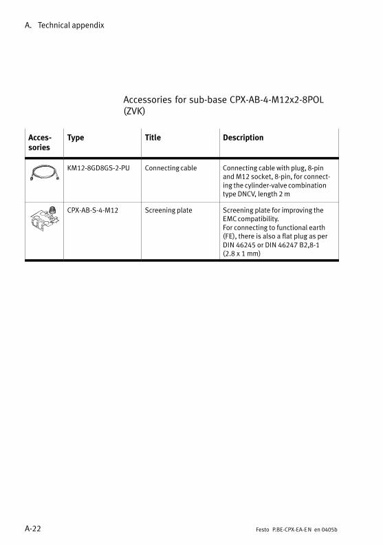
A. Technical appendix
A−22 Festo P.BE−CPX−EA−EN en 0405b
Accessories for sub−base CPX−AB−4−M12x2−8POL(ZVK)
Acces�sories
Type Title Description
KM12−8GD8GS−2−PU Connecting cable Connecting cable with plug, 8−pinand M12 socket, 8−pin, for connect�ing the cylinder−valve combinationtype DNCV, length 2 m
CPX−AB−S−4−M12 Screening plate Screening plate for improving theEMC compatibility.For connecting to functional earth(FE), there is also a flat plug as perDIN�46245 or DIN 46247 B2,8−1 (2.8 x 1 mm)

A. Technical appendix
A−23Festo P.BE−CPX−EA−EN en 0405b
Preparing the plug and cable
Connect the plug and cable as follows (example):
1. In order to open the socket, loosen the centre knurlednut.
2. Open the strain relief at the rear of the housing. Thenpass the cable through.
1 Cable
2 Strain relief
3 Housing
4 Connector part
5 Knurled nut
6 Thread for connectingsocket with knurlednut
12
3
4
56
Fig.�A/8: Individual socket parts and cable routing
3. Remove 5 mm of the insulation from the ends of the con�ductor and fit end sleeves on the strands.
4. Connect the ends of the conductor.
5. Replace the connector part on the housing of the socket.Pull the cable back so that there are no loops inside thehousing.
6. Tighten the strain relief.
A. Technical appendix
A−24 Festo P.BE−CPX−EA−EN en 0405b

Index
B−1Festo P.BE−CPX−EA−EN en 0405b
Appendix B

B. Index
B−2 Festo P.BE−CPX−EA−EN en 0405b
Contents
B. Index B−1 . . . . . . . . . . . . . . . . . . . . . . . . . . . . . . . . . . . . . . . . . . . . . . . . . . . . . . . . .

B. Index
B−3Festo P.BE−CPX−EA−EN en 0405b
AAbbreviationsProduct−specific XVIII . . . . . . . . . . . . . . . . . . . . . . . . . . . . . .
BBehaviour after short circuit 4−17, 5−12, 6−11 . . . . . . . . . . . . .
CCommissioning instructionsInput modules 4−16 . . . . . . . . . . . . . . . . . . . . . . . . . . . . . . . MPA pneumatic modules 2−15 . . . . . . . . . . . . . . . . . . . . . . . Multi I/O modules 6−10 . . . . . . . . . . . . . . . . . . . . . . . . . . . . Output modules 5−11 . . . . . . . . . . . . . . . . . . . . . . . . . . . . . . Pneumatic interfaces 1−15 . . . . . . . . . . . . . . . . . . . . . . . . . .
Connection techniques 3−5 . . . . . . . . . . . . . . . . . . . . . . . . . . . .
CPX I/O modules XIV . . . . . . . . . . . . . . . . . . . . . . . . . . . . . . . .
CPX pneumatic interfaces XII . . . . . . . . . . . . . . . . . . . . . . . . . .
CPX terminalSetting up XVI . . . . . . . . . . . . . . . . . . . . . . . . . . . . . . . . . . . .
CPX−4DAInternal structure A−13 . . . . . . . . . . . . . . . . . . . . . . . . . . . . . Technical specifications A−7 . . . . . . . . . . . . . . . . . . . . . . . . . With sub−base CPX−AB−1−SUB−BU−25POL 5−9 . . . . . . . . . . . . With sub−base CPX−AB−4−HARX2−4POL 5−10 . . . . . . . . . . . . With sub−base CPX−AB−4−M12x2−5POL 5−6 . . . . . . . . . . . . . . With sub−base CPX−AB−8−KL−4POL 5−8 . . . . . . . . . . . . . . . . . . With sub−base CPX−AB−8−M8−3POL 5−7 . . . . . . . . . . . . . . . . .
CPX−4DEInternal structure A−12 . . . . . . . . . . . . . . . . . . . . . . . . . . . . . Technical specifications A−6 . . . . . . . . . . . . . . . . . . . . . . . . . With sub−base CPX−AB−1−SUB−BU−25POL 4−14 . . . . . . . . . . With sub−base CPX−AB−4−HARX2−4POL 4−15 . . . . . . . . . . . . With sub−base CPX−AB−4−M12x2−5POL 4−11 . . . . . . . . . . . . With sub−base CPX−AB−8−KL−4POL 4−13 . . . . . . . . . . . . . . . . With sub−base CPX−AB−8−M8−3POL 4−12 . . . . . . . . . . . . . . .

B. Index
B−4 Festo P.BE−CPX−EA−EN en 0405b
CPX−8DEInternal structure A−12 . . . . . . . . . . . . . . . . . . . . . . . . . . . . . Technical specifications A−6 . . . . . . . . . . . . . . . . . . . . . . . . . With sub−base CPX−AB−1−SUB−BU−25POL 4−9 . . . . . . . . . . . With sub−base CPX−AB−4−HARX2−4POL 4−10 . . . . . . . . . . . . With sub−base CPX−AB−4−M12x2−5POL 4−6 . . . . . . . . . . . . . With sub−base CPX−AB−8−KL−4POL 4−8 . . . . . . . . . . . . . . . . . With sub−base CPX−AB−8−M8−3POL 4−7 . . . . . . . . . . . . . . . .
CPX−8DE−8DAInternal structure A−14 . . . . . . . . . . . . . . . . . . . . . . . . . . . . . Technical specifications A−8 . . . . . . . . . . . . . . . . . . . . . . . . . With sub−base CPX−AB−1−SUB−BU−25POL 6−7 . . . . . . . . . . . . With sub−base CPX−AB−4−M12−8POL 6−8 . . . . . . . . . . . . . . . . With sub−base CPX−AB−8−KL−4POL 6−6 . . . . . . . . . . . . . . . . . .
CPX−AB−1−SUB−BU−25POLConnecting the cables and plugs 3−14 . . . . . . . . . . . . . . . . Technical specifications A−11 . . . . . . . . . . . . . . . . . . . . . . . .
CPX−AB−4−HARX2−4POLConnecting the cables and plugs 3−15 . . . . . . . . . . . . . . . . Technical specifications A−11 . . . . . . . . . . . . . . . . . . . . . . . .
CPX−AB−4−M12−8POLConnecting the cables and plugs 3−17 . . . . . . . . . . . . . . . . Technical specifications A−11 . . . . . . . . . . . . . . . . . . . . . . . .
CPX−AB−4−M12x2−5POLConnecting the cables and plugs 3−10 . . . . . . . . . . . . . . . . Technical specifications A−10 . . . . . . . . . . . . . . . . . . . . . . . .
CPX−AB−8−KL−4POLConnecting the cables and plugs 3−12 . . . . . . . . . . . . . . . . Technical specifications A−10 . . . . . . . . . . . . . . . . . . . . . . . .
CPX−AB−8−M8−3POLConnecting the cables and plugs 3−12 . . . . . . . . . . . . . . . . Technical specifications A−10 . . . . . . . . . . . . . . . . . . . . . . . .
CPX−GP−03−4.0DIL switches 1−12 . . . . . . . . . . . . . . . . . . . . . . . . . . . . . . . . . Technical specifications A−3 . . . . . . . . . . . . . . . . . . . . . . . . .
CPX−GP−CPA−...DIL switches 1−12 . . . . . . . . . . . . . . . . . . . . . . . . . . . . . . . . . Technical specifications A−3 . . . . . . . . . . . . . . . . . . . . . . . . .

B. Index
B−5Festo P.BE−CPX−EA−EN en 0405b
DDesignated use VII . . . . . . . . . . . . . . . . . . . . . . . . . . . . . . . . . .
DiagnosisInput modules 4−20 . . . . . . . . . . . . . . . . . . . . . . . . . . . . . . . MPA pneumatic modules 2−18 . . . . . . . . . . . . . . . . . . . . . . . Multi I/O modules 6−16 . . . . . . . . . . . . . . . . . . . . . . . . . . . . Output modules 5−14 . . . . . . . . . . . . . . . . . . . . . . . . . . . . . . Pneumatic interfaces 1−19 . . . . . . . . . . . . . . . . . . . . . . . . . .
Diagnosis via the field bus XV . . . . . . . . . . . . . . . . . . . . . . . . .
Display and connecting elementsI/O modules 3−7 . . . . . . . . . . . . . . . . . . . . . . . . . . . . . . . . . . . MPA pneumatic modules 2−6 . . . . . . . . . . . . . . . . . . . . . . . . . Pneumatic interfaces 1−6 . . . . . . . . . . . . . . . . . . . . . . . . . . . .
EElectronic module 3−4 . . . . . . . . . . . . . . . . . . . . . . . . . . . . . . .
Examples of circuitryDNCV A−17 . . . . . . . . . . . . . . . . . . . . . . . . . . . . . . . . . . . . . . . DUO cable A−16 . . . . . . . . . . . . . . . . . . . . . . . . . . . . . . . . . . . PNP inputs A−15 . . . . . . . . . . . . . . . . . . . . . . . . . . . . . . . . . . PNP outputs A−15 . . . . . . . . . . . . . . . . . . . . . . . . . . . . . . . . .
FFail safe 1−17, 5−12, 6−14 . . . . . . . . . . . . . . . . . . . . . . . . . . . . . .
Fail safe parametrizing 1−17, 2−16, 5−12, 6−14 . . . . . . . . . . . . .
Fault messagesInput modules 4−20 . . . . . . . . . . . . . . . . . . . . . . . . . . . . . . . MPA pneumatic modules 2−18 . . . . . . . . . . . . . . . . . . . . . . . Multi I/O modules 6−16 . . . . . . . . . . . . . . . . . . . . . . . . . . . . Output modules 5−15 . . . . . . . . . . . . . . . . . . . . . . . . . . . . . . Pneumatic interfaces 1−20 . . . . . . . . . . . . . . . . . . . . . . . . . .
Force 1−18, 5−13, 6−15 . . . . . . . . . . . . . . . . . . . . . . . . . . . . . . . .
Forcing 2−17, 4−19 . . . . . . . . . . . . . . . . . . . . . . . . . . . . . . . . . . .

B. Index
B−6 Festo P.BE−CPX−EA−EN en 0405b
II/O modulesCombinations with sub−bases 3−8 . . . . . . . . . . . . . . . . . . . . . Components 3−4 . . . . . . . . . . . . . . . . . . . . . . . . . . . . . . . . . . Fitting 3−19 . . . . . . . . . . . . . . . . . . . . . . . . . . . . . . . . . . . . . .
Idle mode 1−18, 2−16, 5−13, 6−14 . . . . . . . . . . . . . . . . . . . . . . .
Important user instructions IX . . . . . . . . . . . . . . . . . . . . . . . . . .
Input debounce time 4−17, 6−12 . . . . . . . . . . . . . . . . . . . . . . . .
Input modulesCommissioning instructions 4−16 . . . . . . . . . . . . . . . . . . . . Diagnosis 4−20 . . . . . . . . . . . . . . . . . . . . . . . . . . . . . . . . . . . Fault messages 4−20 . . . . . . . . . . . . . . . . . . . . . . . . . . . . . . . Function 4−4 . . . . . . . . . . . . . . . . . . . . . . . . . . . . . . . . . . . . . Installation 4−5 . . . . . . . . . . . . . . . . . . . . . . . . . . . . . . . . . . . LED display 4−21 . . . . . . . . . . . . . . . . . . . . . . . . . . . . . . . . . . Power supply 4−5 . . . . . . . . . . . . . . . . . . . . . . . . . . . . . . . . . Short circuit/overload 4−22 . . . . . . . . . . . . . . . . . . . . . . . . .
Internal structureCPX−4DA A−13 . . . . . . . . . . . . . . . . . . . . . . . . . . . . . . . . . . . . CPX−4DE A−12 . . . . . . . . . . . . . . . . . . . . . . . . . . . . . . . . . . . . CPX−8DE A−12 . . . . . . . . . . . . . . . . . . . . . . . . . . . . . . . . . . . . CPX−8DE−8DA A−14 . . . . . . . . . . . . . . . . . . . . . . . . . . . . . . . .
LLED displayInput modules 4−21 . . . . . . . . . . . . . . . . . . . . . . . . . . . . . . . MPA pneumatic modules 2−6, 2−19 . . . . . . . . . . . . . . . . . . . . Multi I/O modules 6−18 . . . . . . . . . . . . . . . . . . . . . . . . . . . . Output modules 5−16 . . . . . . . . . . . . . . . . . . . . . . . . . . . . . . Pneumatic interfaces 1−7, 1−21 . . . . . . . . . . . . . . . . . . . . . . .
LED display on the sub−bases 3−7 . . . . . . . . . . . . . . . . . . . . . . .
MManifold sub−base 3−4 . . . . . . . . . . . . . . . . . . . . . . . . . . . . . . .
Module parametersBehaviour after short circuit 4−17, 5−12, 6−11 . . . . . . . . . . . Channel−specific module parameters 1−17, 1−18, . . . . . . . .
2−16, 2−17, 4−18, 4−19, 5−13, 6−13, 6−14, 6−15 . . . . . . . . . Fail safe 5−12, 6−14 . . . . . . . . . . . . . . . . . . . . . . . . . . . . . . . . .

B. Index
B−7Festo P.BE−CPX−EA−EN en 0405b
Fail safe channel x 1−17 . . . . . . . . . . . . . . . . . . . . . . . . . . . . Input debounce time 4−17, 6−12 . . . . . . . . . . . . . . . . . . . . . . Monitoring the CPX module 1−16, 2−15, 4−16, 5−11, 6−10 . . Signal extension time 4−18, 6−13 . . . . . . . . . . . . . . . . . . . . . .
Monitoring the CPX module 1−16, 2−15, 4−16, 5−11, 6−10 . . . .
Monitoring wire fracture 1−17 . . . . . . . . . . . . . . . . . . . . . . . . .
MPA pneumatic modules XIII . . . . . . . . . . . . . . . . . . . . . . . . . . Commissioning instructions 2−15 . . . . . . . . . . . . . . . . . . . . Diagnosis 2−18 . . . . . . . . . . . . . . . . . . . . . . . . . . . . . . . . . . . Fault messages 2−18 . . . . . . . . . . . . . . . . . . . . . . . . . . . . . . . Fitting 2−7 . . . . . . . . . . . . . . . . . . . . . . . . . . . . . . . . . . . . . . . . Function 2−4 . . . . . . . . . . . . . . . . . . . . . . . . . . . . . . . . . . . . . Installation 2−11 . . . . . . . . . . . . . . . . . . . . . . . . . . . . . . . . . . LED display 2−19 . . . . . . . . . . . . . . . . . . . . . . . . . . . . . . . . . . Power supply 2−11 . . . . . . . . . . . . . . . . . . . . . . . . . . . . . . . .
Multi I/O modulesCommissioning instructions 6−10 . . . . . . . . . . . . . . . . . . . . Diagnosis 6−16 . . . . . . . . . . . . . . . . . . . . . . . . . . . . . . . . . . . Fault messages 6−16 . . . . . . . . . . . . . . . . . . . . . . . . . . . . . . . Function 6−4 . . . . . . . . . . . . . . . . . . . . . . . . . . . . . . . . . . . . . Installation 6−5 . . . . . . . . . . . . . . . . . . . . . . . . . . . . . . . . . . . . LED display 6−18 . . . . . . . . . . . . . . . . . . . . . . . . . . . . . . . . . Power supply 6−5 . . . . . . . . . . . . . . . . . . . . . . . . . . . . . . . . . . Short circuit/overload 6−19 . . . . . . . . . . . . . . . . . . . . . . . . .
NNotes on the use of this manual XI . . . . . . . . . . . . . . . . . . . . . .
OOutput modulesCommissioning instructions 5−11 . . . . . . . . . . . . . . . . . . . . Diagnosis 5−14 . . . . . . . . . . . . . . . . . . . . . . . . . . . . . . . . . . . Fault messages 5−15 . . . . . . . . . . . . . . . . . . . . . . . . . . . . . . . Function 5−4 . . . . . . . . . . . . . . . . . . . . . . . . . . . . . . . . . . . . . Installation 5−5 . . . . . . . . . . . . . . . . . . . . . . . . . . . . . . . . . . . . LED display 5−16 . . . . . . . . . . . . . . . . . . . . . . . . . . . . . . . . . . Power supply 5−5 . . . . . . . . . . . . . . . . . . . . . . . . . . . . . . . . . . Short circuit/overload 5−17 . . . . . . . . . . . . . . . . . . . . . . . . .

B. Index
B−8 Festo P.BE−CPX−EA−EN en 0405b
PPictograms X . . . . . . . . . . . . . . . . . . . . . . . . . . . . . . . . . . . . . . .
Pin assignmentCPX−4DA− with sub−base CPX−AB−1−SUB−BU−25POL 5−9 . . . . . . . . . − with sub−base CPX−AB−4−HARX2−4POL 5−10 . . . . . . . . . − with sub−base CPX−AB−4−M12x2−5POL 5−6 . . . . . . . . . . . − with sub−base CPX−AB−8−KL−4POL 5−8 . . . . . . . . . . . . . . . − with sub−base CPX−AB−8−M8−3POL 5−7 . . . . . . . . . . . . . .
CPX−4DE− with sub−base CPX−AB−1−SUB−BU−25POL 4−14 . . . . . . . − with sub−base CPX−AB−4−HARX2−4POL 4−15 . . . . . . . . . − with sub−base CPX−AB−4−M12x2−5POL 4−11 . . . . . . . . . − with sub−base CPX−AB−8−KL−4POL 4−13 . . . . . . . . . . . . . − with sub−base CPX−AB−8−M8−3POL 4−12 . . . . . . . . . . . .
CPX−8DE− with sub−base CPX−AB−1−SUB−BU−25POL 4−9 . . . . . . . . − with sub−base CPX−AB−4−HARX2−4POL 4−10 . . . . . . . . . − with sub−base CPX−AB−4−M12x2−5POL 4−6 . . . . . . . . . . − with sub−base CPX−AB−8−KL−4POL 4−8 . . . . . . . . . . . . . . − with sub−base CPX−AB−8−M8−3POL 4−7 . . . . . . . . . . . . .
CPX−8DE−8DA− with sub−base CPX−AB−1−SUB−BU−25POL 6−7 . . . . . . . . . − with sub−base CPX−AB−4−M12−8POL 6−8 . . . . . . . . . . . . . − with sub−base CPX−AB−8−KL−4POL 6−6 . . . . . . . . . . . . . . .
Pneumatic interfaceFunction 1−4 . . . . . . . . . . . . . . . . . . . . . . . . . . . . . . . . . . . . .
Pneumatic interfacesCommissioning instructions 1−15 . . . . . . . . . . . . . . . . . . . . Diagnosis 1−19 . . . . . . . . . . . . . . . . . . . . . . . . . . . . . . . . . . . DIL switches 1−9 . . . . . . . . . . . . . . . . . . . . . . . . . . . . . . . . . . . Fault messages 1−20 . . . . . . . . . . . . . . . . . . . . . . . . . . . . . . . Fitting 1−8 . . . . . . . . . . . . . . . . . . . . . . . . . . . . . . . . . . . . . . . . Installation 1−14 . . . . . . . . . . . . . . . . . . . . . . . . . . . . . . . . . . LED display 1−21 . . . . . . . . . . . . . . . . . . . . . . . . . . . . . . . . . . Power supply 1−14 . . . . . . . . . . . . . . . . . . . . . . . . . . . . . . . .
Power supply 1−14, 2−11, 4−5, 5−5, 6−5 . . . . . . . . . . . . . . . . . . .
Protection class 1−14, 2−13, 3−9, 3−14, A−3, . . . . . . . . . . . . . . . A−4, A−5, A−10, A−11 . . . . . . . . . . . . . . . . . . . . . . . . . . . . . . . .

B. Index
B−9Festo P.BE−CPX−EA−EN en 0405b
SScreening plateConnecting 3−10, 3−17 . . . . . . . . . . . . . . . . . . . . . . . . . . . . . . Fitting 3−22 . . . . . . . . . . . . . . . . . . . . . . . . . . . . . . . . . . . . . .
Service VIII . . . . . . . . . . . . . . . . . . . . . . . . . . . . . . . . . . . . . . . .
Short circuit/overload 4−22, 5−17, 6−19 . . . . . . . . . . . . . . . . . .
Signal extension time 4−18, 6−13 . . . . . . . . . . . . . . . . . . . . . . . .
Sub−base CPX−AB−1−SUB−BU−25POLOverview 3−6 . . . . . . . . . . . . . . . . . . . . . . . . . . . . . . . . . . . . . . With I module CPX−4DE 4−14 . . . . . . . . . . . . . . . . . . . . . . . . With I module CPX−8DE 4−9 . . . . . . . . . . . . . . . . . . . . . . . . . With multi I/O module CPX−8DE−8DA 6−7 . . . . . . . . . . . . . . . With O module CPX−4DA 5−9 . . . . . . . . . . . . . . . . . . . . . . . . .
Sub−base CPX−AB−4−HARX2−4POLOverview 3−6 . . . . . . . . . . . . . . . . . . . . . . . . . . . . . . . . . . . . . . With I module CPX−4DE 4−15 . . . . . . . . . . . . . . . . . . . . . . . . With I module CPX−8DE 4−10 . . . . . . . . . . . . . . . . . . . . . . . . With O module CPX−4DA 5−10 . . . . . . . . . . . . . . . . . . . . . . .
Sub−base CPX−AB−4−M12−8POLOverview 3−6 . . . . . . . . . . . . . . . . . . . . . . . . . . . . . . . . . . . . . . With multi I/O module CPX−8DE−8DA 6−8 . . . . . . . . . . . . . . .
Sub−base CPX−AB−4−M12x2−5POLOverview 3−5 . . . . . . . . . . . . . . . . . . . . . . . . . . . . . . . . . . . . . . With I module CPX−4DE 4−11 . . . . . . . . . . . . . . . . . . . . . . . . With I module CPX−8DE 4−6 . . . . . . . . . . . . . . . . . . . . . . . . . With O module CPX−4DA 5−6 . . . . . . . . . . . . . . . . . . . . . . . . .
Sub−base CPX−AB−8−KL−4POLOverview 3−5 . . . . . . . . . . . . . . . . . . . . . . . . . . . . . . . . . . . . . . With I module CPX−4DE 4−13 . . . . . . . . . . . . . . . . . . . . . . . . With I module CPX−8DE 4−8 . . . . . . . . . . . . . . . . . . . . . . . . . With multi I/O module CPX−8DE−8DA 6−6 . . . . . . . . . . . . . . . With O module CPX−4DA 5−8 . . . . . . . . . . . . . . . . . . . . . . . . .
Sub−base CPX−AB−8−M8−3POLOverview 3−5 . . . . . . . . . . . . . . . . . . . . . . . . . . . . . . . . . . . . . . With I module CPX−4DE 4−12 . . . . . . . . . . . . . . . . . . . . . . . . With I module CPX−8DE 4−7 . . . . . . . . . . . . . . . . . . . . . . . . . With O module CPX−4DA 5−7 . . . . . . . . . . . . . . . . . . . . . . . . .
Sub−basesCombinations with I/O modules 3−8 . . . . . . . . . . . . . . . . . . . Connecting the cables and plugs 3−9 . . . . . . . . . . . . . . . . . . Overview 3−4, 3−5 . . . . . . . . . . . . . . . . . . . . . . . . . . . . . . . . . .

B. Index
B−10 Festo P.BE−CPX−EA−EN en 0405b
TTarget group VIII . . . . . . . . . . . . . . . . . . . . . . . . . . . . . . . . . . . .
Technical specificationsCPX−4DA A−7 . . . . . . . . . . . . . . . . . . . . . . . . . . . . . . . . . . . . . CPX−4DE A−6 . . . . . . . . . . . . . . . . . . . . . . . . . . . . . . . . . . . . . CPX−8DE A−6 . . . . . . . . . . . . . . . . . . . . . . . . . . . . . . . . . . . . . CPX−8DE−8DA A−8 . . . . . . . . . . . . . . . . . . . . . . . . . . . . . . . . . CPX−AB−1−SUB−BU−25POL A−11 . . . . . . . . . . . . . . . . . . . . . . CPX−AB−2−KL−4POL A−10 . . . . . . . . . . . . . . . . . . . . . . . . . . . . CPX−AB−4−HARX2−4POL A−11 . . . . . . . . . . . . . . . . . . . . . . . . CPX−AB−4−M12−8POL A−11 . . . . . . . . . . . . . . . . . . . . . . . . . . CPX−AB−4−M12x2−5POL A−10 . . . . . . . . . . . . . . . . . . . . . . . . CPX−AB−8−M8−3POL A−10 . . . . . . . . . . . . . . . . . . . . . . . . . . . CPX−GP−03−4.0 A−3 . . . . . . . . . . . . . . . . . . . . . . . . . . . . . . . . CPX−GP−CPA−... A−3 . . . . . . . . . . . . . . . . . . . . . . . . . . . . . . . . Input modules A−6 . . . . . . . . . . . . . . . . . . . . . . . . . . . . . . . . MPA electronic modules A−4 . . . . . . . . . . . . . . . . . . . . . . . . Multi I/O modules A−8 . . . . . . . . . . . . . . . . . . . . . . . . . . . . . Output modules A−7 . . . . . . . . . . . . . . . . . . . . . . . . . . . . . . . Pneumatic interfaces A−3 . . . . . . . . . . . . . . . . . . . . . . . . . . . Sub−bases A−10 . . . . . . . . . . . . . . . . . . . . . . . . . . . . . . . . . . . VMPA1−FB−EMG−8 A−4 . . . . . . . . . . . . . . . . . . . . . . . . . . . . . . VMPA1−FB−EMS−8 A−4 . . . . . . . . . . . . . . . . . . . . . . . . . . . . . .
Text markings X . . . . . . . . . . . . . . . . . . . . . . . . . . . . . . . . . . . . .
VVMPA1−FB−EMG−8Technical specifications A−4 . . . . . . . . . . . . . . . . . . . . . . . . .
VMPA1−FB−EMS−8Technical specifications A−4 . . . . . . . . . . . . . . . . . . . . . . . . .