cra infrastructure engineering, inc. of the facility requires regulatory review by new york state...
TRANSCRIPT
~ CRA Infrastructure ~ & Engineering, Inc.
NIAGARA BIOENERGY ANAEROBIC DIGESTER SYSTEM (ADS) FACILITY INITIAL INST ALLA TI ON
SUBPART 360-1.9(B) NONSPECIFIC FACILITIES SOLID WASTE MANAGEMENT PERMIT APPLICATION
AND
SUBPART 201-5 STATE FACILITY PERMITS APPLICATION
D ISCLAIM ER:
SOME FORMATTING C HANGES M AY HAVE OCCURRED WHEN
THE ORIGINAL DOCUMENT WAS PRI NTED TO PDF; HOWEVER,
THE ORIGINAL CO NT ENT REMAINS UNCHANG ED.
JUNE2012 R EF. NO. 077364-02 (1)
Prepared b y: CRA Infrastructure & Engineering, Inc.
2055 Niagara Falls Blvd. Suite Three Niagara Falls, NY 14304
Office: (716) 297-6150 Fax: (716) 297-2265
web: http:\\www.CRAworld.com
TABLE OF CONTENTS
Received N.Y.S. DEPT OF
JUL 0 9 2012
ENVIRONMENTAL CONSERVATION REGION 9 Page
1.0 INTRODUCTION .............................................. .. .................................................... ............... 1 1.1 DESCRIPTION .................... ..................... .................................................. ......... 2 1.2 CONSISTENCY WITH STATE AND LOCAL
WASTE MANAGEMENT POLICIES ............................................................... 2 1.3 FACILITY PERMITTING/REGISTRATIONS ............................. ................... 2 1.4 REPORT ORGANIZATION ....... ....... ................................................................ 3
2.0 SITE LOCATION AND LAYOUT .. ...... .......................... ............................................ .... ...... 4 2.1 SITE LOCATION ........................................... ..................................................... 4 2.2 SITE LAYOUT .................................. ............. ................................................ ...... 4 2.3 PROPOSED SERVICE AREA ............................................................................ 4 2.4 BIOMASS ACCEPTANCE PROTOCOL.. .............. ................. ......................... 5
3.0 ADS FACILITY DESIGN .................. .................................................... ............................... 12 3.1 ADS FACILITY COMPONENTS ......... ........................................................... 12 3.2 DESIGN CAPACITY ..................................................... ................................... 12 3.3 PROCESS FLOW ........... ..................................................... ... ..... .............. ......... 12
4.0 OPERATIONS AND MAINTENANCE PLAN .............. .................................................. 15 4.1 DAILY LOGISfICS ...... ..................................................................... ................ 15 4.2 LOADING AND UNLOADING PROCEDURES ......................................... 15 4.3 ODOR CONTROL ................... ..................................................................... .... 15 4.4 NOISE CONTROL .......................................... .. ...... .......................... ... ............. 15 4.5 MAINTENANCE .... ............................... ........................................................... 16 4.6 OPERATIONAL LIFE ...................................................................................... 16
5.0 WASTE CONTROL PLAN ................... ................................................................ .......... ..... 17 5.1 GENERATING FACILITIES ............. ................................................ ............... 17 5.2 TREATMENT, HANDLING, AND DISPOSAL OF WASTE .. .................... 17 5.2.1 LIQUID WASTE ................................................................................................ 17 5.2.2 SOLID WASTE ................................................................................... ............... 17
6.0 AIR STATE FACILITY PERMIT APPLICATION ............................................................ 18
7.0 CONTINGENCY PLAN ......................................................................................... ............ . 19 7.1 PERSONAL INJURY .... ............................................. ......................... .. ............ 19 7.2 PROCESS AND CONTROLS ................................. ................................. ........ 20 7.3 FIRES ...................................... ... ......................................... ................................. 20 7.4 SPILLS .................. ................. .................. ............................... ............................. 20 7.5 STORMW ATER ............... ........................... ............................ ......... ... .. ............. 21
oms4 (1 ) CRA INFRASTRUCTURE & ENGINEERING, INC.

FIGURE 2.1
FIGURE2.2
FIGURE3.1
APPENDIX A
APPENDIXB
APPENDIXC
APPENDIXD
077364 (1)
LIST OF FIGURES
SITE LOCATION MAP
SITE LAYOUT
PROCESS FLOW DIAGRAM
LIST OF APPENDICES
APPLICATION FOR SOLID WASTE MANAGEMENT FACILITY PERMIT FORM
QEG BACKGROUND INFORMATION
SITE DRAWINGS
AIR ST A TE FACILITY PERMIT APPLICATION
CRA INFRASTRUCTURE & ENGINEERING, INC.

1.0 INTRODUCTION
077364 (1)
Quasar Energy Group (QEG) is a Oeveland, Ohio based renewable energy company. The
QEG complete mix anaerobic digestion system (ADS) processes biomass waste to produce
clean, renewable energy and valuable by-products. Anaerobic digestion can be a cost
effective solution for organic waste generators limited by new EPA regulations. In Ohio,
QEG currently has six BioEnergy projects operational, and two in the design stage. QEG
background information is presented in Appendix B.
QEG is proposing the installation and operation of a BioEnergy ADS on Liberty Drive in
the Town of Wheatfield, Niagara County, New York. The Wheatfield BioEnergy ADS
Facility (Facility), applies advanced anaerobic digestion technology to recycle energy from
organic waste (biomass). Anaerobic digestion is a natural process where microorganisms
break down biomass in the absence of oxygen. The technology has been commonly used in
Europe, with over 8,000 systems in operation today. In the United States, anaerobic
digestion is emerging as a key component of the country's renewable energy portfolio.
Permitting of the Facility requires regulatory review by New York State Department of
Environmental Conservation (NYSDEC) under Part 360: Solid Waste Management
Facilities. The purpose of Part 360, as noted in subdivision 360-1.l(a), is "to regulate solid
waste management facilities other than hazardous waste management facilities that are
subject to Parts 372, 373, 376, or Subparts 374-1 and 374-3 of this Title and facilities
managing radioactive materials, naturally-occurring and accelerator-produced radioactive
(NARM) waste and low-level radioactive waste that are subject to Parts 380, 382, and 383 of
this Title and located partially or wholly within the state of New York. Hence, except
where the context indicates otherwise, the term solid waste management facility refers to
facilities that are not subject to Part 372, 373,376, 380, 382, 383 or Subparts 374-1 and 374-3
of this Title. 11
In light of the above purpose, and as required in subdivision 360-1.8(c) of Part 360, CRA
Infrastructure & Engineering, Inc. (CRA), on behalf of QEG, pursued pre-application
meetings with NYSDEC to address the development of a complete application pertaining
to QEG' s project. CRA contacted representatives of NYSDEC and on April 18, 2012, met with representatives of NYSDEC at their Region 9 office in Buffalo, NY. Through
discussion, it was determined that the proposed QEG facility would be specifically
regulated under subpart 360-l.9(b) for "non-specific" facilities and under 6 NYCRR
Part 201-5.l(a)(3) for an Air State Facility Permit.
CRA INFRASTRUCTURE & ENGINEERING, INC.

077364 (1)
1.1 DESCRIPTION
The proposed QEG Facility will accept liquid and solid biomasses such as organic solids,
food wastes, oil and grease, mainly from Niagara Cormty. The biomass will be initially
processed in a 230,000 gallon digester tank for equalization purposes and ultimately in a
750,000 gallon dual-purpose digester tank. A blower will convey collected biogas from the
digester tank, through a hydrogen sulfide scrubber, to a Caterpillar G3520C internal
combustion (IC) engine. The IC engine will convert biogas to electricity for sale to the open
market. A backup flare will be used in the event that the IC engine is down for
maintenance purposes or for any rmplanned outages. In addition, heat from the IC engine
will be recirculated to the tanks via heat exchanger process. A biogas boiler will be used to
provide additional energy required to maintain proper temperature for the anaerobic
digestion process.
1.2 CONSISTENCY WITH ST ATE AND LOCAL WASTE MANAGEMENT POLICIES
NYSDEC Policy DSH-SW-05-01 Solid Waste Management Policy Guidance provides an
ordered listing of preferred solid waste management methodologies of Section 27-0106 of
the Environmental Conservation Law (ECL). In descending order of preference, they are 1)
Reduce, 2) Reuse, 3) Recover energy, and 4) Dispose. The proposed QEG ADS facility is
consistent with ECL 27-0106 second and third preferred methodologies for managing solid
wastes in a manner that will reduce dependency on land burial or raw wastes. The Facility
will improve the regional environment by processing organic waste that would otherwise
be sent to landfills, while producing clean, renewable energy. In addition, the system will
produce valuable by-products of nutrient rich soil amendments that are desired regionally.
1.3 FACILITY PERMITIING/REGISTRATIONS
The proposed QEG facility will be permitted under subpart 360-1.9(b) for "non-specific"
facilities and under 6 NYCRR Part 201-5.1(a)(3) for an Air State Facility Permit. After
discussion with NYSDEC, CRA recognizes that in accordance with subdivision 360-1.S(d)
of this Part, QEG may be permitted to construct the Facility as identified in the application,
subject to any appropriate conditions NYSDEC may impose; and, that the permitted
Facility cannot begin operation until demonstrated to NYSDEC's satisfaction that the
facility has been constructed in accordance with the permit issued for the facility, and
criteria for permit issuance provided in section 360-1.10 of the Part have been satisfied.
2 CRA INFRASTRUCTURE & ENGINEERING, INC.

077364 (1)
It is further understood that the permittee is responsible for obtaining any other permits,
approvals, lands, easements and rights-of-way that may be required to carry out the
activities that are authorized by this permit.
Though QEG has not contracted with potential end users at the time of this application,
QEG understands that beneficial use of the post-digestion nutrient rich soil amendments
on farmland, forest land, public works projects, landscaping activities, and land
reclamation will require permits; and, the lands and farms will need to analyze and adjust
their permits to use the material in this environmentally sound, socially acceptable, and
cost-effective manner.
1.4 REPORT ORGANIZATION
CRA was provided verbal guidance by a NYSDEC representative, as well as the
opportunity to review a similar facility application that was NYSDEC-approved for a Solid
Waste Management Permit and an Air State Facility Permit. Based on the verbal guidance
and like the previously NYSDEC-approved facility application, this engineering report is
organized and intended to meet required elements of both the Part 360 permit application
and the Part 201 Air State Facility Permit Application.
CRA submits the following documents as supporting information for the Solid Waste
Management Facility Permit Application and the Air State Facility Permit Application.
• Site plans, detailed Facility layout, and proposed service area (see Section 2.0)
• Description of ADS facility components, design capacity and process flow (see
Section 3.0)
• Description of operations and maintenance with consideration given to handling
procedures, odor control, and noise control (see Section 4.0) • Description of the sources of biomass, and how the system will handle the biomass, and
disposal of waste, liquid waste and solid waste (see Section 5.0)
• Emissions Inventory - Air State Facility Permit Application (see Section 6.0)
• Air State Facility Permit Application Forms (Appendix D) • Contingency plans for responding to unexpected events during construction and
operations (see Section 7.0)
• Application for Solid Waste Management Facility Permit Form (Appendix A)
• QEG Background Information (Appendix B)
• Site Plan Drawings (Appendix C)
3 CRA INFRASTRUCTURE & ENGINEERING, INC.
2.0 SITE LOCATION AND LAYOUT
077364 (1)
2.1 SITE LOCATION
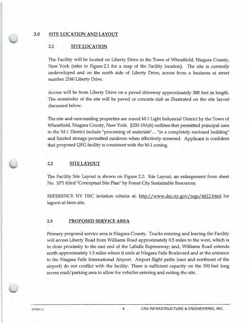
The Facility will be located on Liberty Drive in the Town of Wheatfield, Niagara County,
New York (refer to Figure 2.1 for a map of the Facility location). The site is currently
undeveloped and on the north side of Liberty Drive, across from a business at street
number 2160 Liberty Drive.
Access will be from Liberty Drive on a paved driveway approximately 300 feet in length.
The remainder of the site will be paved or concrete slab as illustrated on the site layout
discussed below.
The site and surrounding properties are zoned M-1 Light Industrial District by the Town of
Wheatfield, Niagara County, New York. §200-19A(6) outlines that permitted principal uses
in the M-1 District include "processing of materials" ... "in a completely enclosed building"
and limited storage permitted outdoors when effectively screened. Applicant is confident
that proposed QEG facility is consistent with the M-1 zoning.
2.2 SITE LAYOUT
The Facility Site Layout is shown on Figure 2.2: Site Layout, an enlargement from sheet
No. SP1 titled "Conceptual Site Plan" by Forest City Sustainable Resources.
REFERENCE NY DEC isolation criteria at: http://www.dec.ny.gov/regs/ 4412.html for
lagoon at farm site.
2.3 PROPOSED SERVICE AREA
Primary proposed service area is Niagara County. Trucks entering and leaving the Facility
will access Liberty Road from Williams Road approximately 0.5 miles to the west, which is
in close proximity to the east end of the LaSalle Expressway; and, Williams Road extends
north approximately 1.5 miles where it ends at Niagara Falls Boulevard and at the entrance
to the Niagara Falls International Airport. Airport flight paths (east and northeast of the
airport) do not conflict with the facility. There is sufficient capacity on the 300 feet long
access road/parking area to allow for vehicles entering and exiting the site.
4 CRA INFRASTRUCTURE & ENGINEERING, INC.
077364 (1)
2.4 BIOMASS ACCEPTANCE PROTOCOL
The Facility operates under a protocol for biomass acceptance with limits for various
pollutants, requirements for pre-approval, and mandates for records and manifests as
detailed in the following pages, which is their protocol of September 28, 2011, REV 5, or updated versions, as appropriate.
5 CRA INFRASTRUCTURE & ENGINEERING, INC.
9/28/11 Revs
ANAEROBIC DIGESTION FACILITY
BIOMASS ACCEPTANCE PROTOCOL
1. Only pre-approved materials from approved sources are accepted at this facility.
No hazardous waste is accepted at this facility.
2. Truck drivers will have to be pre-approved tluough background check and present
picture ID with deliveries.
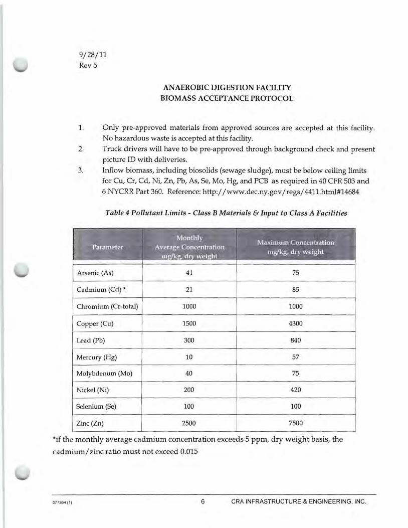
3. Inflow biomass, including biosolids (sewage sludge), must be below ceiling limits
for Cu, Cr, Cd, Ni, Zn, Pb, As, Se, Mo, Hg, and PCB as required in 40 CFR 503 and
6 NYCRR Part 360. Reference:http://www.dec.ny.gov/ regs/ 4411.html#14684
Table 4 Pollutant Limits - Class B Materials & Input to Class A Facilities
f· •. ·. '·~~~~~~-~-----~ '\'1.1-·rl .# l ,.... . , •. • • . .
.. 4~)\ol; l',, ·~ ~°1" .' "\ ··-.J~~), I • ' • -. ',:'[· '~Ci/:k£""•·) . .:,.'· :.: C t;: .. ·-~ :il., ·· :Maxunum ConcenlTation.1;-•.·;;·.1: 1 Parameter .. · ,•Average oncentrahon ~ ~ . . . "
.· --~~·-;;,- - -' • -~·-.-.. .1:.:; .~"·; ,- ~ · •· •. -.- • :- J~ mg/kg, dry we1nht · ·-- 'I ·"..'.......~·.Ol 1:!'. y :i~m ; Cir ·;we1 ht ~_:lt3i.~· · ·· · ·. . 0 }'..:::..t !
Arsenic (As) 41 75
Cadmium (Cd) * 21 85
Chromium (Cr-total) 1000 1000
Copper (Cu) 1500 4300
Lead (Pb) 300 840
Mercury (Hg) 10 57
Molybdenum (Mo) 40 75
Nickel (Ni) 200 420
Selenium (Se) 100 100
Zinc (Zn) 2500 7500
*if the monthly average cadmium concentration exceeds 5 ppm, dry weight basis, the
cadmium/ zinc ratio must not exceed 0.015
077364 (1) 6 CRA INFRASTRUCTURE & ENGINEERING, INC.

077364 (1)
Table 5 Cumulative Metal Loading Limits
~· .. 'C ill . ·I!' d' L ( t r~-"f/C,... ... ~,J."'"~·~ .--, . - -· --,..""'!!""",.,-:""""~~ ·:. - ·1: ljo. ri ...... 1 . I .... ~ ! • :~·- ~ -. I
~-··- ,, .. \.-:'<\-·· s '"l'G~~ · 1"" '·· S 'JG .... 4!.0 " l!,.;...,~2-..,,.·~J, •Lg., Ol -..: roup~ -.:> J,iJ A". 01 rottps· 1 l~
Cadmium 3 4
Chromium 300 446
Copper 75 112
Lead 267 267
Nickel 30 45
Zinc 150 223
4. Bio-solid generators must provide their historical and quarterly NPDES permit
limits and analytical data to QEG for prior approval. The EPA is aware of pollutants
in specific wastewater treatment plants that may be of concern in addition to the
Federal rules and regulations.
5. This facility will not accept loads with plastic bed liners or chemical treatments to
keep loads from freezing or sticking to the truck bed.
6. A Manifest will be required in addition to a weight slip.
7. See below for detailed requirements and restrictions.
7 CRA INFRASTRUCTURE & ENGINEERING, INC.
077364 (1)
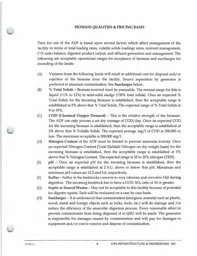
BIOMASS QUALITIES & PRICING BASIS
Price for use of the ADF is based upon several factors which affect management of the
facility in terms of total loading rates, volatile solids loadings rates, nutrient management,
C:N ratio balance, digested product output, and effluent generation and management. The
following are acceptable operational ranges for acceptance of biomass and surcharges for
exceeding of the limits:
(A) Variance from the following limits will result in additional cost for disposal and/ or
rejection of the biomass from the facility. Source separation by generator is
preferred to eliminate contamination. See Surcharges below.
(B) % Total Solids - Biomass received must be pumpable. The normal range for this is
liquid (<1 % to 12%) to semi-solid sludge (<30% total solids). Once an expected %
Total Solids for the incoming biomass is established, then the acceptable range is
established at 5% above that % Total Solids. The expected range of % Total Solids is
9to19%.
(C) COD (Chemical Oxygen Demand) - This is the relative strength of the biomass.
The ADF can only process a set dry tonnage of COD/day. Once an expected COD
for the incoming biomass is established, then the acceptable range is established at
5% above that % Volatile Solids. The expected average mg/l of COD is 200,000 or
less. The maximum acceptable is 300,000 mg/1.
(D) Nitrogen Content of the ADF must be limited to prevent ammonia toxicity. Once
an expected Nitrogen Content (Total Kjeldahl Nitrogen on dry weight basis) for the
incoming biomass is established, then the acceptable range is established at 5%
above that % Nitrogen Content. The expected range is 10 to 20% nitrogen (TKN).
(E) pH - Once an expected pH for the incoming biomass is established, then the
acceptable range is established at 2 S.U. above or below that pH Maximum and
minimum pH values are 12.5 and 5.0, respectively. (F) Sulfur - Sulfur in the feedstocks converts to very odorous and corrosive H2S during
digestion. The incoming feedstock has to have a COD: S04 ratio of 10 or greater.
(G) Septic or Soured Wastes - May not be acceptable to this facility because of potential
for digester upsets. Each will be evaluated on a case by case basis. (H) Surcharges - It is understood that contamination (inorganic material such as plastic,
wood, metal and foreign objects such as locks, tools, etc.) will do damage and / or
reduce the efficiency of the anaerobic digestion process. Every reasonable effort to
prevent contaminants from being disposed of at QEG will be made. The generator
is responsible for damages caused by contamination and will pay for damages to
equipment and/ or cost to remove and dispose of contamination.
8 CRA INFRASTRUCTURE & ENGINEERING, INC.
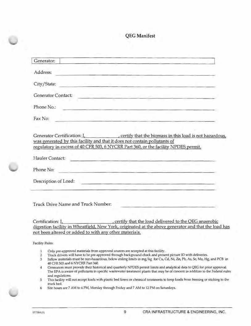
QEG Manifest
I Generator:
Address:
City /State:
Generator Contact:
Phone No.:
Fax No:
Generator Certification: I, , certify that the biomass in this load is not hazardous, was generated by this facility and that it does not contain pollutants of regulatory in excess of 40 CFR 503, 6 NYCRR Part 360, or the facility NPDES permit.
Hauler Contact:
Phone No:
Description of Load:
Truck Drive Name and Truck Number:
Certification: I, , certify that the load delivered to the QEG anaerobic digestion facility in Wheatfield, New York, originated at the above generator and that the load has not been altered or added to with any other materials.
Facility Rules:
1 Only pre-approved ma terials from approved sources are accepted at this facility. 2 Truck drivers will have to be pre-approved through background check and present picture ID with deliveries. 3 Inflow materials must be non-hazardous, below ceiling limits in m g/ kg for Cu, Cd, Ni, Zn, Pb, As, Se, Mo, Hg, and PCB in
40 CFR 503 and 6 NYCRR Part 360. 4 Genera tors must provide their historical and quarterly NPDES permit limits and analytical da ta to QEG for prior approval.
The EPA is aware of pollutants in specific wastewater treatment plants tha t may be of concern in addition to the Federal rules and regulations.
5 This facility will not accept loads with plastic bed liners or chemical treatments to keep loads from freezing or sticking to the truck bed.
6 Site hours are 7 AM to 4 PM, Monday through Friday and 7 AM to 12 PM on Saturdays.
077364 (1) 9 CRA INFRASTRUCTURE & ENGINEERING, INC.
077364 (1)
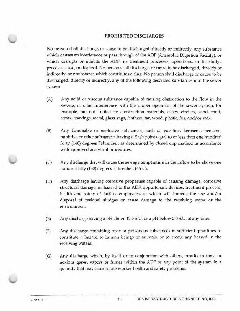
PROHIBITED DISCHARGES
No person shall discharge, or cause to be discharged, directly or indirectly, any substance
which causes an interference or pass through of the ADF (Anaerobic Digestion Facility), or
which disrupts or inhibits the ADF, its treatment processes, operations, or its sludge
processes, use, or disposal. No person shall discharge, or cause to be discharged, directly or
indirectly, any substance which constitutes a slug. No person shall discharge or cause to be
discharged, directly or indirectly, any of the following described substances into the sewer
system:
(A) Any solid or viscous substance capable of causing obstruction to the flow in the
sewers, or other interference with the proper operation of the sewer system, for
example, but not limited to: construction materials, ashes, cinders, sand, mud,
straw, shavings, metal, glass, rags, feathers, tar, wood, plastic, fur, and/ or wax.
(B) Any flammable or explosive substances, such as gasoline, kerosene, benzene,
naphtha, or other substances having a flash point equal to or less than one hundred
forty (140) degrees Fahrenheit as determined by closed cup method in accordance
with approved analytical procedures.
(C) Any discharge that will cause the sewage temperature in the inflow to be above one
hundred fifty (150) degrees Fahrenheit (66°C).
(D) Any discharge having corrosive properties capable of causing damage, corrosive
structural damage, or hazard to the ADF, appurtenant devices, treatment process,
health and safety of facility employees, or which will impede the use and/ or
disposal of residual sludges or cause damage to the receiving water or the
environment.
(E) Any discharge having a pH above 12.5 S.U. or a pH below 5.0 S.U. at any time.
(F) Any discharge containing toxic or poisonous substances in sufficient quantities to
constitute a hazard to human beings or animals, or to create any hazard in the
receiving waters.
(G) Any discharge which, by itself or in conjunction with others, results in toxic or
noxious gases, vapors or fumes within the ADF or any point of the system in a
quantity that may cause acute worker health and safety problems.
10 CRA INFRASTRUCTURE & ENGINEERING, INC.

077364 (1)
(H) Any discharge which contains an objectionable color not removed by the ADF such
as, but not limited to, dye wastes and vegetable tanning solutions.
(I) Any discharge containing radioactive waste except:
(1) When the user is authorized to use radioactive materials by the State Department of Health or other governmental agency empowered to regulate the
use of radioactive materials
(2) When the waste is discharged in strict conformity with current regulations of
the Applicable Environmental Protection Agency and the Nuclear Regulatory
Commission regulations and reconunendations for safe disposal
(3) When the user is in compliance with all rules and regulations of this chapter and
all other applicable regulatory agencies; and
(4) When there is no harmful effect on city personnel, sewer system, sludges, or
receiving stream.
(J) Any used oil or petroleum based materials.
(K) Any discharge that result in an exceedance of ten (10) percent of the lower explosive
limit in the air at any point within the ADF.
(L) Any discharge of silver-rich solutions from a photographic processing facility,
unless such silver-rich solution is managed by a photographic processing facility in
accordance with the Silver CMP prior to its discharge.
11 CRA INFRASTRUCTURE & ENGINEERING, INC.

3.0 ADS FACILITY DESIGN
077364 (1)
3.1 ADS FACILITY COMPONENTS
The Facility is a modular design sized to match the controlled annual inputs anticipated for
the services area. The electrical, mechanical, monitoring and controls are balanced to
efficiently recycle energy from organic waste. The following components, as illustrated in Figure 2.2 Site Layout, are included:
• Digester/Duel Purpose Tartk
• Feedstock Holding Tartk (Biomass equalization)
• Solids Receiving Pit
• Below Grade Liquid Receiving Tartk (typ of 2) • H2S Scrubber
• Containerized CHP unit
• Flare • Plant building
• Biofilter
3.2 DESIGN CAP A CITY
The ecoFARMsystem 980 (F980) has a tartk capacity of 980,000 gallons. Normal digestion
time is 20 to 30 days for inputs of pumpable organic biomass with an annual input of
52,524 wet tons (144 tons/ day).
Component
Dual Purpose Tank
Equalization Tartk
Liquid Receiving Tanks
Solids Receiving Pit
3.3 PROCESS FLOW
Capacity
750,000 gallons
230,000 gallons
12,000 gallons (each)
30 cubic yards
QEG's process begins by introducing biomass to the system. Biomass from municipal
wastewater treatment facilities, agricultural sources, alcohol and ethanol distillers, and
food manufacturing companies can be accepted in either liquid or solid form.
12 CRA INFRASTRUCTURE & ENGINEERING, INC.
077364 (1)
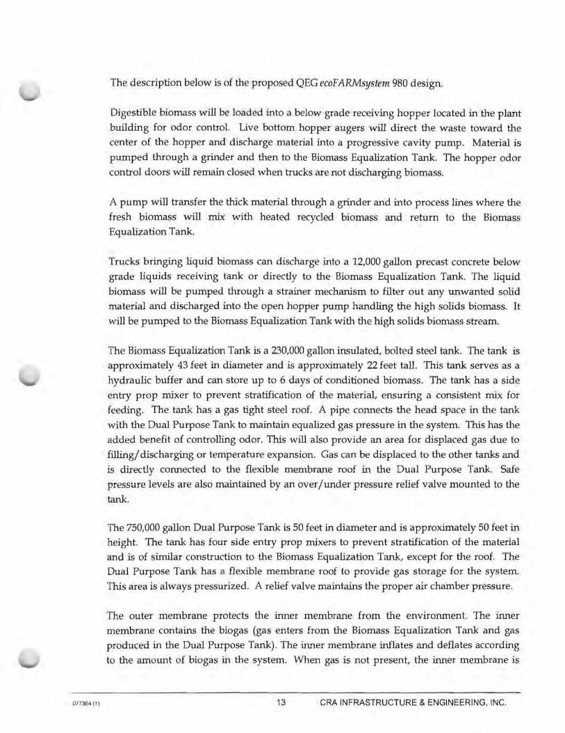
The description below is of the proposed QEG ecoF ARMsystem 980 design.
Digestible biomass will be loaded into a below grade receiving hopper located in the plant
building for odor control. Live bottom hopper augers will direct the waste toward the
center of the hopper and discharge material into a progressive cavity pump. Material is
pumped through a grinder and then to the Biomass Equalization Tank. The hopper odor
control doors will remain closed when trucks are not discharging biomass.
A pump will transfer the thick material through a grinder and into process lines where the
fresh biomass will mix with heated recycled biomass and return to the Biomass Equalization Tank.
Trucks bringing liquid biomass can discharge into a 12,000 gallon precast concrete below
grade liquids receiving tank or directly to the Biomass Equalization Tank. The liquid
biomass will be pumped through a strainer mechanism to filter out any unwanted solid
material and discharged into the open hopper pump handling the high solids biomass. It
will be pumped to the Biomass Equalization Tank with the high solids biomass stream.
The Biomass Equalization Tank is a 230,000 gallon insulated, bolted steel tank. The tank is
approximately 43 feet in diameter and is approximately 22 feet tall. This tank serves as a
hydraulic buffer and can store up to 6 days of conditioned biomass. The tank has a side
entry prop mixer to prevent stratification of the material, ensuring a consistent mix for
feeding. The tank has a gas tight steel roof. A pipe connects the head space in the tank
with the Dual Purpose Tank to maintain equalized gas pressure in the system. This has the
added benefit of controlling odor. This will also provide an area for displaced gas due to
filling/ discharging or temperature expansion. Gas can be displaced to the other tanks and
is directly connected to the flexible membrane roof in the Dual Purpose Tank. Safe
pressure levels are also maintained by an over/under pressure relief valve mounted to the
tank.
The 750,000 gallon Dual Purpose Tank is 50 feet in diameter and is approximately 50 feet in
height. The tank has four side entry prop mixers to prevent stratification of the material
and is of similar construction to the Biomass Equalization Tank, except for the roof. The
Dual Purpose Tank has a flexible membrane roof to provide gas storage for the system.
This area is always pressurized. A relief valve maintains the proper air chamber pressure.
The outer membrane protects the inner membrane from the environment. The inner
membrane contains the biogas (gas enters from the Biomass Equalization Tank and gas
produced in the Dual Purpose Tank). The inner membrane inflates and deflates according
to the amount of biogas in the system. When gas is not present, the inner membrane is
13 CRA INFRASTRUCTURE & ENGINEERING, INC.

077364 (1)
supported by a column and cable system to keep the membrane from contacting the
biomass.
Collected biogas is conveyed by a blower through a hydrogen sulfide scrubber and then
used to fuel a boiler and a CHP unit. Natural gas is available as a back-up source of fuel.
The Facility has one containerized CHP unit, a Caterpillar G3520C IC engine, with a
capacity of 2,233 brake horsepower (BHP) that will generate approximately 1.3 MW /hour of electrical power. The Facility will process an average of 144 tons of biomass per day,
generating biogas at a rate of 400 - 500 scfm @ 55% to 60% CH4. The F980 also has a
backup flare that can be used in the event that the CHP unit is down for maintenance
purposes or for any unplanned outages.
While producing clean renewable energy, the F980 will produce 30,000-35,000 gallons/ day
of nutrient rich fertilizer for land application (See Figure 3.1: Process Flow Diagram).
14 CRA INFRASTRUCTURE & ENGINEERING, INC.
4.0 OPERATIONS AND MAINTENANCE PLAN
077364 (1)
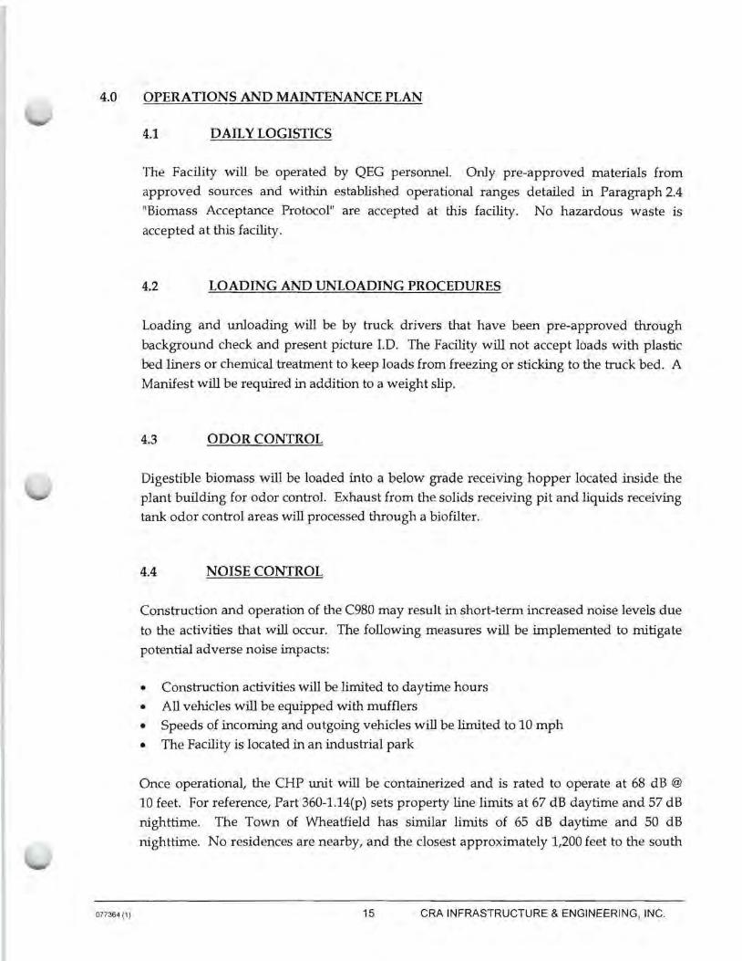
4.1 DAILY LOGISTICS
The Facility will be operated by QEG personnel. Only pre-approved materials from
approved sources and within established operational ranges detailed in Paragraph 2.4
"Biomass Acceptance Protocol" are accepted at this facility. No hazardous waste is
accepted at this facility.
4.2 LOADING AND UNLOADING PROCEDURES
Loading and unloading will be by truck drivers that have been pre-approved through
background check and present picture l.D. The Facility will not accept loads with plastic
bed liners or chemical treatment to keep loads from freezing or sticking to the truck bed. A
Manifest will be required in addition to a weight slip.
4.3 ODOR CONTROL
Digestible biomass will be loaded into a below grade receiving hopper located inside the
plant building for odor control. Exhaust from the solids receiving pit and liquids receiving
tank odor control areas will processed through a biofilter.
4.4 NOISE CONTROL
Construction and operation of the C980 may result in short-term increased noise levels due
to the activities that will occur. The following measures will be implemented to mitigate
potential adverse noise impacts:
• Construction activities will be limited to daytime hours
• All vehicles will be equipped with mufflers
• Speeds of incoming and outgoing vehicles will be limited to 10 mph
• The Facility is located in an industrial park
Once operational, the CHP unit will be containerized and is rated to operate at 68 dB @
10 feet. For reference, Part 360-1.14(p) sets property line limits at 67 dB daytime and 57 dB
nighttime. The Town of Wheatfield has similar limits of 65 dB daytime and 50 dB
nighttime. No residences are nearby, and the closest approximately 1,200 feet to the south
15 CRA INFRASTRUCTURE & ENGINEERING, INC.

077364 (1)
on River Road and on the other side of a wooded area and, much of this wooded area is
designated "federal wetlands" on mapping maintained on the Town of Wheatfield website.
4.5 MAINTENANCE
Routine maintenance of the Facility will be by QEG personnel. Should non-routine
expertise beyond QEG ability be required, appropriate contractors will be secured, as
needed, to properly maintain the Facility.
4.6 OPERA TI ON AL LIFE
Materials employed in the construction of the Facility are typically expected to have a
minimum 20-year useful life. The Facility as a whole, with routine maintenance and
replacement as pieces and parts expire, will operate in perpetuity.
16 CRA INFRASTRUCTURE & ENGINEERING, INC.

5.0 WASTE CONTROL PLAN
077364 (1)
5.1 GENERATING FACILITIES
Biomass generating facilities will be pre-approved for materials from approved sources
and within established operational ranges. Due to transport expense, biomass generating
facilities are likely to be from within the county.
5.2 TREATMENT, HANDLING, AND DISPOSAL OF WASTE
Biomass will be transported to the Facility from various generating facilities in tanker
trucks or otherwise containerized. Unloading and loading will be a closed process or
indoors with the doors closed in the case of biomass solids.
5.2.1 LIQUID WASTE
Incoming liquid biomass will be controlled in a closed process. Liquids out of the Facility
will be pumped into tanker trucks and transported out to land application or off-site
storage for future sale/use.
5.2.2 SOLID WASTE
Non-digestible solid waste will be sent to a licensed municipal solid waste landfill.
17 CRA INFRASTRUCTURE & ENGINEERING, INC.

077364 (1)
6.0 AIR STATE FACILITY PERMIT APPLICATION
The Air State Facility Permit Application is included with this Engineering Report as
Appendix D.
18 CRA INFRASTRUCTURE & ENGINEERING, INC.
7.0 CONTINGENCY PLAN
077364 (1)
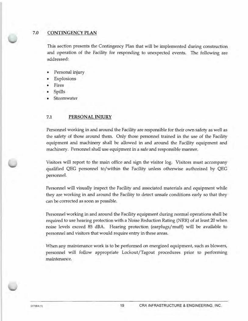
This section presents the Contingency Plan that will be implemented during construction
and operation of the Facility for responding to unexpected events. The following are
addressed:
• Personal injury
• Explosions
• Fires
• Spills
• Storm water
7.1 PERSONAL INJURY
Personnel working in and around the Facility are responsible for their own safety as well as
the safety of those around them. Only those personnel trained in the use of the Facility
equipment and machinery shall be allowed in and around the Facility equipment and
machinery. Personnel shall use equipment in a safe and responsible manner.
Visitors will report to the main office and sign the visitor log. Visitors must accompany
qualified QEG personnel to/within the Facility unless otherwise authorized by QEG
personnel.
Personnel will visually inspect the Facility and associated materials and equipment while
they are working in and around the Facility to detect unsafe conditions early so that they
can be corrected as soon as possible.
Personnel working in and around the Facility equipment during normal operations shall be required to use hearing protection with a Noise Reduction Rating (NRR) of at least 20 when
noise levels exceed 85 dBA. Hearing protection (earplugs/muff) will be available to
personnel and visitors that would require entry in these areas.
When any maintenance work is to be performed on energized equipment, such as blowers,
personnel will follow appropriate Lockout/Tagout procedures prior to performing
maintenance.
19 CRA INFRASTRUCTURE & ENGINEERING, INC.

077364 (1 I
7.2 PROCESS AND CONTROLS
Methane detectors are present in the Plant Building of the Facility. Sensors are set to alarm
at 10 percent of the lower explosive limit (LEL). In the event of an explosion during
operation of the ADS facility, personnel will inunediately clear the area, and the local fire
department will immediately be notified.
7.3 FIRES
The Facility Plant Building is equipped with smoke detectors and alarms. In the event that
a fire is detected during either construction or operation of the Facility, personnel will
immediately clear the area, and the local fire department will immediately be notified.
7.4 SPILLS
In the unlikely event of a spill during transportation to or within the Facility, QEG
personnel will take the following immediate actions:
Halt the Source of the Spill
Contain Spill - As appropriate, use straw bales to form a barrier.
Cleanup- Employ vacuum truck cleaning up large quantities of sludge.
Final Cleanup - As appropriate, flush roadways with water immediately after sludge is
removed from the spill site, or sweep as necessary to clean. In the event a spill occurs on
private property, the owner will be contacted immediately, and final cleanup will be completed to the satisfaction of the owner.
Management of Cleanup Efforts - QEG personnel shall take immediate charge and initiate
cleanup activities. Labor shall be secured as needed. QEG personnel shall also be on hand
to communicate with the public or media on the scene, answering questions and advising
of cleanup activities.
Notification - Dispatch Manager to notify Operations Managers with exact location, time
of occurrence, and conditions of spill.
20 CRA INFRASTRUCTURE & ENGINEERING, INC.

077364 (1)
IMMEDIATE NOTIFICATION will be given by Operations in the following order:
NYSDEC District Office or Emergency Spill Number.
Dispatch to notify Resource and Materials (R&M) Manager about spill and needed
equipment for cleanup.
R&M Manager to notify Managers if vacuum truck and/ or personnel assistance is
required.
Dispatch to obtain necessary information about spill such as police report and to follow-up
as necessary to bill other parties for insurance claims.
Spill prevention - QEG sh-.11 take the following steps:
Ensure truck dnVt. ip truck while loading at plant.
Ensure that tailgate seals are in place on ur 1p trucks. If not, they will be replaced
or repaired as necessary.
Inspect trucks daily and replace or repair as necessary.
Ensure tarps are in place while transporting.
Ensure unloading operations in the field are conducted so as to minimize any
spillage.
7.5 STORMWATER
Storrnwater pollution prevention and erosion control during the construction activities at
the Facility are addressed on the Site Plan Drawings attached to this Engineering Report as
Appendix C.
21 CRA INFRASTRUCTURE & ENGINEERING, INC.

MAP 1 1
TOWN
OF"
WHEATFIELD
VISION MAP
0 MUHIQIP ... L. Dl:llJl<QAllY
COMMUNITY F"AC:IL.ITilta
EJ •~-n ~ n HOO•••WY
mt * Nl....a.o. ...... CauNT"r WATS:•
~ --· * Oo""'"o~c ••a•~,~• .t ···~· * TDWN P' ... lllUTT
~ N
l<EY TO F'EATUREB
COMMUNITY 1111.CIUTI•
- llJD"'l'l_g .... 1.
• I rcrrun1>11. L.1"'1Tl'.A CCM,..un11A1.
- llDTIUolTIA ... ~llA (.A""lll:l'Jll"'"''rcl
'ZZ NIA•-· ,. ... 1-4-.. •LVD./ ................ C"CIOC civou. .......
COMMUNITY A11&Aa
\ \ ...... cun l'"l.H:O•T l"ATH
• l"••O::• "t1.,..1.1:r"A1UA•
- INDUSTRIAL.
- MIX&D U111 A•&A
,.. ADllLDUL.Tl.J"IC "'"lTl:CIOlllH All .....
- C:D-UUl!.o.L. "1:ci:vc1.a .. ,..i:11T A•~
* P'llDl'Cll:D .. l:DlllTlllAN ClllDlllllHa
• Ti-1111 M ..... l!I A "''CT'Cl-L. •c .. ,,.c•l:NT,.TINQ er THC V•••i:IN CIP'"!"l-111: PLAN
'-ND lll"ICIULD lllt Ull~ '"' CCl .... JUNCTICN Wl'Tl"I Tl"llt COl'f,.IU::l"ICl'lllllVlt Pl-A.No
IT coca NOT 1::n: .. "JT LA"ID Ua.: Cl.II :Z:CNlNlll·
~ WENDEL a D UCHSCHERER
.. t f:" I ~ t I'. T ~ .0 I'. t..' C: I ... [ r <I I
PROJECT# 29S603MP Auou•T 2003
SANBORN
2,000 0 2,000 4,000
E-3 ~ IF"Eli:T
, .... ,...cioooio•.D"'""'"-·,.., ...... o,,.,...,.,.._.,., .. ur .. ,.n~ .. -..,.,,,...,......,0..., .......... LU& ... ,'"'"'.,_ ................... 1: .. c • .:"1Q .. 0' ·-............. TA.C:'•Lm ..... ..
O.A.MYlllODleUl"''"'"'""'"....,T«l .. TA~•MlllO"<:ITT'""" .. _,.•U.Do<oll ... CLJ_...U
"'"""'"""'....-"'"..,,,n""'"'""'"'''"'........,'"""""""""-Dll
Slu1.11.dc
-Tigure

Figure 2-2: Site Layout

Receiving Pracast
Com:rele Tank 12,000 gal
,----------·~ 11 ~HP Gensel
:;. '1'
CHP/Boller Waler Retirculallon Pump [* Oesulfuritalion
Blower
Exhaust lrorn Odor
;;+
H2S Scrubber Skid
Blooas Pipe ~~~I
Receiving Precasl
Concrete Tank 12,000 gal
1 £ j " a ~
1 x Side En1~ BlomeS.:3 Mixer Equalization
,..-. \. Tank I M · 230.000 ge1 .. __ ....
Incoming Uquld Biomass from Truck
Rec.lro.Aatlon/Heatlng Pump
90 GPM @ 60 psi
(M' ... _ _,,.
4 x Side Enlry Mixers
Dual-Purpose Tank 750,000 Gauon
cl I l--1-1----,1.
Plant Building
O!;l8'Sl.t!r Cmmis!kming BypaK une
U\•e Bollom Hopper JO cubic yards
Open Hopper Pump 325 GPM el 60 psi
/c Gr1nder/Mllcerator
Uquid Fcoding Bypass
-------<*t-<-------< lnlol/DilullorvOullel
Pump 100 GPM@ 60 psi
Solids Receiving Pil
Blower
emuen1 Transfer Pump 3000 GPM @4~
BlofiUer
To Land Appllcallcn or
Off·slle Storage
....
~ quC!.~,~.r
quuar•ner;rgmup 7G24~1¥61·,..RoOld
PO Bo• 31023 C!Olfolll"'10H-44141 Phc:r:.c:216.DOG.ll959
NaltoScalD .,.,_,._, ........ ,,___ _ __....,. ....,_ _ _,,.. ..... ...., ........ ...... ........, .,. ._..~ .... ~~ ........ ...., ... _ .,, ................... _ _,_,_ ..,_......_ .............. --. ... ..._.. .......... _ ......... -............ ...--- ....... -~ ~ • .-• ..,-... 1)1. - .. .-~<lld-w.
& IA
.)>-
? :§!
0
9."'° 0
o I EPASl,IWTfAI.
""'· ECt:Ntll'lbor
0066·01G-01 00
Oa10
Process Flow Diagram
GOer.-HtA-NY-11 vnioe!lliltl BIOEnol\)y
I } ! I ~ ~
I I I ~
i f I
ADSF.-d:lr ~ oc:oFennS-'{tUlm too :I
. =~-~- I I~ 1~ l~I 1
~mG10i111. LLC. Al "al'!Mrtiltvllf1 .a...-hm!J!
Figure 3.1
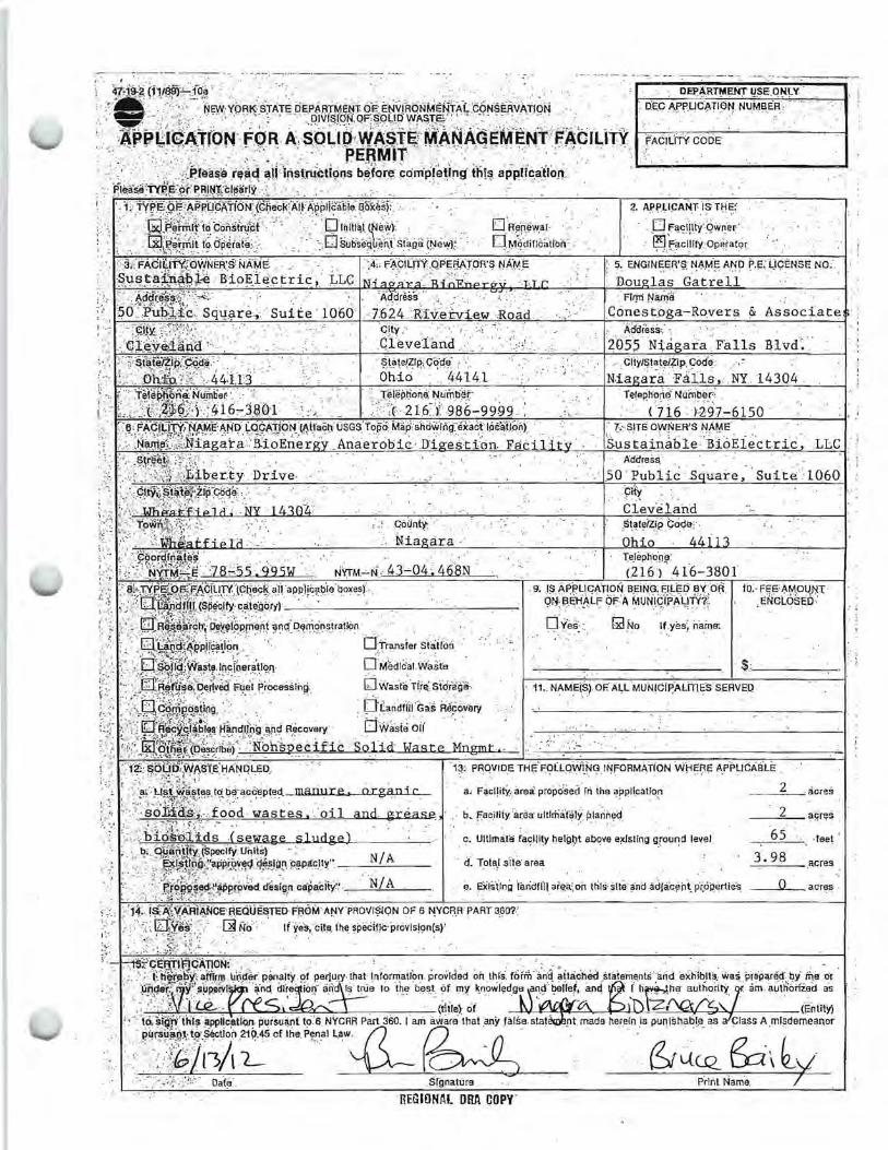
<: ikFAC!fit:Y.;owNER'S'NAME ',' ,j.:, FACiLri'Y QPEMTOR'S NAME ' ~- ENGINEER'$ NA,fyl-!O AN!J P.E. (ICENSE NO; _ ~-\l~~~ii,~n,~~}i BioEJ~ctric, J.LC .. -· . - · · " :;··.: -- -- -· · .. . Dou las Gatrell
, _. ·~d~,~~I~~~~q\J_{lre~ ·Suite· i060 · _ .J·~ia~~~~v:~fview Road ..
"·-· '. ~drt~~i~~~~ -- . ~~Y~velan~ ,· - -- , io~~r~~~~gata .. Falls ~lvd'. _·
FlrM Nail:!-0 Conestoga-Rovers & Associate
·~ !~-.~· $,l~~~~w::~~f. > _.: ,_ ,· $ta\el:t;IP,{Ctf~e .· · , . CltylStateiZip c6de _-_ ;·/ . -0-hfo.'. ,;: : 44·1.13 · OhiO · __ 44141 N.ia ~rFiAi1~ . . NY t43Q4 _
l ··- L.Je.trr!~$~X~t4f:6~3'e01 -_ ----.:, · · ::-?:~iepi~ni:~r~~~-~9999 . - _.. . TefeP.~0;!~u~~i~:1-615o · ·' r-5, FACiiJty,;·NAME" ANO' L.ocAtibN (Aitach OsGs'topo: Ma# showing: exad loc~fo~ii) . kS.ITE ow~ER'S NA~E :\ ·;:· .. ~.:-.~~~;~~:~~.fii~·g~t-~-~::·ii~E~-e·~·, .. · ·· _ Aria:e·~·Obi~>-:n·i· -~--~:-(:i:On.-.F~·tii· ·. · ~ .Sustainitble: B.iOEiec t:ri·C :LLC · ; ,.
: ; ;,:~;~;~~~Fr-:~h~r-ty Dr.lve, - _, 50 A~~~iic .S uare, ·Suit¢ 1060 ' 1
· - · · c1i:Y~- ~foite 1:zif code" . 91~ _ _ ..
·• '.} t•i~~;:';, ·. · ... : • ·. ~::"~ra .·· . ~~·::t;~4 · \: ~:'.:~~~@~g; }8~5s.99SW ' N~M~~i .. 4J~04 .. 468N - -- ' ~eie;~()~~416~380l
. 9; _IS AF'P.LlcA'r10N BEiNG; FILED BY OR to> FEE' AMOUJ•f( · cirfBEHALF OF ,\ MUN1C:'i-Pi\'t:rNi'. · - · ENcl.osED · •. ·=. -.- · ·. .. •• •· .' • •· •• •· .. ~· .. · . ~·: • • :
0-ves - . IX! No rt.yes; name: •' ..
dri~i1 1c~a1w~~10 $ _____ _
b Wasti TfiEf s!Ciiag'a-. ' 11 •. NAME(Sj. OF.: ALL'MUNICl~ALITIES SERVEQ
§'~;~~~~1as A-~~o~e~_ . . .
''+''.J¥k§iit~;?:ZC>~~rili~(<N~hspecifiC - Solid· Waste Mngmt.. - -,.---- ~-.,..":_--,:...~--------------~----! , i 1~f::~~:~:~:r~st£)_:lANQLED; . . -- 1~: PR.OVIDE TH\:'F:OLLQiiii}I~ INfORM~TION W~~f:IE AP-PU CABLE .
' " a, :. u llt -wiistes ta tie·acceptect manure, organic a' FacllitY..area propdsed rri iha applicatro'.1 I ·. " . • ~,;-:\.._· .: , ;· :1~-.~~~·.~·" · · ... ' ... _.:;>• ,. : ' • ' . . • •
" •:<solii\&s:; .food w.aste.s. _oil and grease_ • ti. f'ac;1riy ·a~i!aurtlriia·ra1Y:µranned : .. • • l • ~ ::;:,; .,,~·:~ or :-" - .. . . . . . .· . · · ·.,., b"icHmJ:.ids (sewa.ge sludge)
b; bti'ii:MltY.. (speelfY uii1ls) -<- - · NI A
.... ·.~'.~If ~:l~;:;:::~;~.•--N~/~A-~- e. Eli!si1ng 1aridflH aiE!a' on tfirs site and adJac¢nt~ p(opertie·s
2 . acres
2 ajj~~ -
65 ·feet
3.98 acres
Q acres
. o; urtrrttate faclll.ty helgl)t above ex]stlng g,.round le~e l
· ii. Tota,! sitir area
REGIONAL ORA ol'Jpy·
AIR ST ATE FACILITY PERMIT APPLICATION
QUASARENERGYGROU~LLC
WHEATFIELD BIOENERGY ANAEROBIC DIGESTION FACILITY WHEATFIELD, NEW YORK
JUNE2012 REF. NO. 077364 (1)
77364 (1)
SECTION 1
EMISSIONS INVENTORY
EMISSIONS INVENTORY JUNE2012
QUASAR ENERGY GROUP, LLC WHEATFIELD BIOENERGY ANAEROBIC DIGESTION FACILITY WHEATFIELD, NEW YORK
}UNE2012 REF. NO. 077364 (1)
TABLE OF CONTENTS
1.0 INTRODUCTION ........................................................ ........................................................... 1
2.0 FACILITY EMISSION UNIT DESCRIPTIONS ................................................................... 2 2.1 FACILITY EMISSION SOURCES ..................................... ................................ 2 2.2 SUMMARY OF EMISSIONS AND SOURCES ............................................ ... 2 2.2.1 BIOGAS COMBUSTION .................................................................................... 2 2.2.1.1 CATERPILLAR G3520C IC ENGINE ............................................................... 3 2.2.1.2 BACKUP FLARE .......................................................... ................. ...................... 4 2.2.2 BIOFILTER ............ .............. ........................................................................ ......... 5 2.2.3 EXEMPT SOURCES ............................................................................................ 5 2.2.3.1 BIOGAS-FIRED BOILER [6 NYCRR 201-3.2(C)(2)] ...... .... .... .......................... 5
3.0 EMISSION DISCUSSION ...................................................................................................... 6
4.0 REGULA TORY REVIEW ...................................................................................... ................. 7 4.1 40 CFR PART 60, SUBPART JJJJ ..... ................................................................... 7 4.2 40 CFR PART 63, SUBPART ZZZZ ................................ .................................. 8
77364 (1 l CONESTOGA-ROVERS & A S SOCIA TES

FIGURE 1
FIGURE 2
TABLE 1
TABLE 2
TABLE2A
TABLE2B
TABLE3
TABLE3A
TABLE3B
TABLE4
TABLES
LIST OF FIGURES
MAP OF FACILITY LOCATION
PROCESS FLOW DIAGRAM
LIST OF TABLES
SUMMARY OF POTENTIAL EMISSIONS
SUMMARY OF CATERPILLAR G3520C ENGINE EMISSIONS
SUMMARY OF CATERPILLAR G3520C ENGINE HAP EMISSIONS
SUMMARY OF CATERPILLAR G3520C ENGINE GREENHOUSE GAS EMISSIONS
SUMMARY OF BACKUP FLARE EMISSIONS
SUMMARY OF BACKUP FLARE HAP EMISSIONS
SUMMARY OF CATERPILLAR G3520C ENGINE GREENHOUSE GAS EMISSIONS
SUMMARY OF BIOFILTER EMISSIONS
SUMMARY OF BIOGAS-FIRED BOILER EMISSIONS
LIST OF ATTACHMENTS
ATTACHMENT 1 CATERPILLAR G3520C ENGINE MANUFACTURER SPECIFICATIONS
77364 (1) CONESTOGA- ROVERS & ASSOCIATES

1.0 INTRODUCTION
77364 (1)
Conestoga-Rovers & Associates, Inc. (CRA) has been retained by Quasar Energy Group,
LLC (QEG) to conduct an emissions inventory of the proposed Wheatfield Bioenergy
anaerobic digestion facility (ADF) to be located in Wheatfield, New York. The emissions
inventory (Inventory) will be used to establish emission rates and biogas collection and
control system design features for the Facility. The Inventory will also be used as a basis
for the Air State Facility Application to authorize the construction and operation of the
Wheatfield Bioenergy ADF.
The proposed ADF will be located at Liberty Drive, Wheatfield, New York (refer to
Figure 1 for a map of the Facility location). The Facility will accept liquid and solid
biomasses such as food waste, agricultural waste, and sewage sludge, mainly from
Niagara County. The biomass will be initially processed in a 230,000 gallon equalization
tank for stabilization purposes and ultimately to a 750,000 gallon digester tank. A blower
will convey collected biogas from the digester tank to a Caterpillar G3520C internal
combustion (IC) engine. The IC engine will convert biogas to electricity for sale to the
open market. A backup flare will be used in the event that the IC engine is down for
maintenance purposes or for any unplanned outages. In addition, heat from the IC
engine will be recirculated to the tanks via heat exchanger process. A biogas-fired boiler
will be used to provide any additional energy required to maintain proper temperature
for the anaerobic digestion process. Figure 2 provides the process flow diagram for the
proposed Facility.
The Standard Industrial Oassification (SIC) for the Facility is 4953.
CONESTOGA- ROVERS & ASSOCIATES
2.0 FACILITY EMISSION UNIT DESCRIPTIONS
77364 (1)
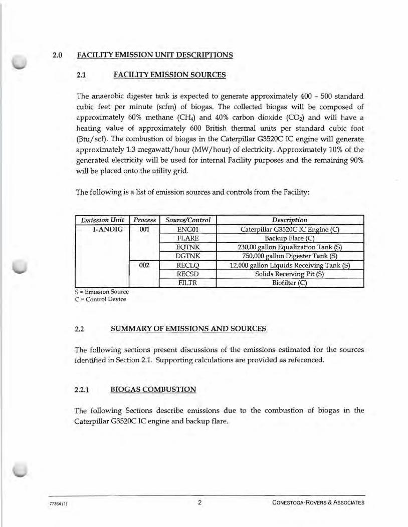
2.1 FACILITY EMISSION SOURCES
The anaerobic digester tank is expected to generate approximately 400 - 500 standard
cubic feet per minute (scfm) of biogas. The collected biogas will be composed of
approximately 60% methane (C~) and 40% carbon dioxide (C02) and will have a
heating value of approximately 600 British thermal units per standard cubic foot
(Btu/ scf). The combustion of biogas in the Caterpillar G3520C IC engine will generate
approximately 1.3 megawatt/hour (MW /hour) of electricity. Approximately 10% of the
generated electricity will be used for internal Facility purposes and the remaining 90%
will be placed onto the utility grid.
The following is a list of emission sources and controls from the Facility:
Emission Unit 1-ANDIG
S = Emission Source C = Control Device
Process 001
002
Source/Control
ENGOl FLARE EQTNK DGTNK RECLQ RECSD FILTR
Description Caterpillar G3520C IC Engine (C)
Backup Flare (C)
230,00 gallon Equalization Tank (S) 750,000 gallon Digester Tank (S)
12,000 gallon Liquids Receiving Tank (S)
Solids Receiving Pit (S) Biofilter (C)
2.2 SUMMARY OF EMISSIONS AND SOURCES
The following sections present discussions of the emissions estimated for the sources identified in Section 2.1. Supporting calculations are provided as referenced.
2.2.1 BIOGAS COMBUSTION
The following Sections describe emissions due to the combustion of biogas in the
Caterpillar G3520C IC engine and backup flare.
2 CONESTOGA-ROVERS & ASSOCIATES
77364 (1 )
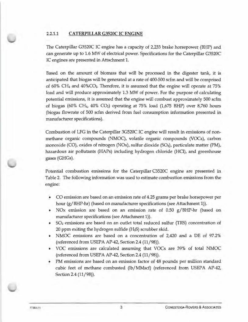
2.2.1.1 CATERPILLAR G3520C IC ENGINE
The Caterpillar G3520C IC engine has a capacity of 2,233 brake horsepower (BHP) and
can generate up to 1.6 MW of electrical power. Specifications for the Caterpillar G3520C
IC engines are presented in Attachment 1.
Based on the amount of biomass that will be processed in the digester tank, it is
anticipated that biogas will be generated at a rate of 400-500 scfm and will be comprised
of 60% Cr4 and 40%C02. Therefore, it is assumed that the engine will operate at 75%
load and will produce approximately 1.3 MW of power. For the purpose of calculating
potential emissions, it is assumed that the engine will combust approximately 500 scfm
of biogas (60% Cr4, 40% C02) operating at 75% load (1,675 BHP) over 8,760 hours
(biogas flowrate of 500 scfm derived from fuel consumption information presented in
manufacturer specifications).
Combustion of LFG in the Caterpillar 3G520C IC engine will result in emissions of non
methane organic compounds (NMOC), volatile organic compounds (VOCs), carbon
monoxide (CO), oxides of nitrogen (NOx), sulfur dioxide (S02), particulate matter (PM),
hazardous air pollutants (HAPs) including hydrogen chloride (HO), and greenhouse
gases (GHGs).
Potential combustion emissions for the Caterpillar C3520C engine are presented in
Table 2. The following information was used to estimate combustion emissions from the
engine:
• CO emission are based on an emission rate of 4.25 grams per brake horsepower per
hour (g/BHP-hr) (based on manufacturer specifications (see Attachment 1)).
• NOx emission are based on an emission rate of 0.50 g/BHP-hr (based on
manufacturer specifications (see Attachment 1)). • S02 emissions are based on an outlet total reduced sulfur (TRS) concentration of
20 ppm exiting the hydrogen sulfide (HiS) scrubber skid.
• NMOC emissions are based on a concentration of 2,420 and a DE of 97.2%
(referenced from USEPA AP-42, Section 2.4 (11/98)).
• VOC emissions are calculated assuming that VOCs are 39% of total NMOC
(referenced from USEPA AP-42, Section 2.4 (11/98)).
• PM emissions are based on an emission factor of 48 pounds per million standard
cubic feet of methane combusted (lb/MMscf) (referenced from USEPA AP-42,
Section 2.4 (11/98)) .
3 CONESTOGA- ROVERS & A SSOCIATES

77364 (1)
Emissions of speciated HAP compounds from the engine were calculated based on
concentrations referenced from the Waste Industry Air Coalition (WIAC). The
concentration of HCl was referenced from "Measurement of Toxic Emissions from
Landfill: History and Current Developments (Sullivan, Patrick S. and Bins, Jolm,
November 2002). 11 A destruction efficiency of 98% was assumed in the calculations.
Speciated HAP emissions for the engine are provided in Table 2A.
GHG emissions for Caterpillar G3520C IC engine were calculated by assuming that the
collected biogas is approximately 60% methane and 40% carbon dioxide by volume.
Anthropogenic GHG emissions in terms of carbon dioxide equivalents were calculated
by assuming global warming potential values referenced from 40 CFR Part 98,
Subpart A. Table 4B presents the calculated GHG emissions from the engine.
2.2.1.2 BACKUP FLARE
A backup flare will be used in the event that the IC engine is down for maintenance
purposes or for any unplanned outages. Emissions were calculated assuming a biogas
flowrate of 500 scfm over 8,760 hours.
The following information was used to estimate combustion emissions from the backup
open flare:
• CO and NOx emissions are based on a CO emission rate of 0.37 lb/MMBTU and a
NOx emission rate of 0.068 lb/MMBTU (referenced from USEPA AP-42, Section
13.5 (09/91)) . • S02 emissions are based on an outlet total reduced sulfur (TRS) concentration of
20 ppm exiting the hydrogen sulfide (H2S) scrubber skid.
• NMOC emissions are based on a concentration of 2,420 and a DE of 98.0% (referenced from USEPA AP-42, Section 2.4 (11/98)).
• VOC emissions are calculated assuming that VOCs are 39% of total NMOC (referenced from USEPA AP-42, Section 2.4 (11/98)).
• PM emissions are based on an emission factor of 17 lb/MMScf (referenced from USEPA AP-42, Section 2.4 (11/98)).
Emissions of speciated HAP compounds from the flare were calculated based on
concentrations referenced from WIAC. The concentration of HCl was referenced from
"Measurement of Toxic Emissions from Landfill: History and Current Developments
(Sullivan, Patrick S. and Bins, Jolm, November 2002)." A destruction efficiency of 98%
4 CONESTOGA-ROVERS & ASSOCIATES

77364 (1)
was assumed in the calculations. Speciated HAP emissions for the flares are provided in
Table 3A.
GHG emissions from the flare were calculated by assuming that LFG is approximately
60% methane and 40% carbon dioxide by volume. Anthropogenic GHG emissions in
terms of carbon dioxide equivalents were calculated by assuming global warming
potential values referenced from 40 CFR Part 98, Subpart A. Table 3B presents the
calculated GHG emissions from combustion of LFG in the flare.
2.2.2 BIO FILTER
A biofilter will be installed to reduce odors that may accumulate within the solids
receiving pit and the liquids receiving tank. A fan will collect air from these areas and
exhaust to a biofilter bed (approximately 9' x 20' x 6') that has a removal efficiency of
approximately 90%. Table 4 presents the expected potential emissions from the biofilter.
2.2.3 EXEMPT SOURCES
The following sections give a description of emission sources that are considered exempt
under 6 NYCRR 201-3.2(c).
2.2.3.1 BIOGAS-FIRED BOILER [6 NYCRR 201-3.2(C)(2)]
Heat for the digester tank, equalization tank and any facility buildings are provided by a
biogas fired boiler. Since the capacity of the boiler is less than 10 million Btu/hour, this
unit is considered exempt from permitting. Emission factors for biogas combustion in
the boiler were referenced from Table 3 (emission factors for biogas combustion in flare
were utilized). Table 5 presents a summary of emissions from the biogas boiler.
5 CONESTOGA-ROVERS & A SSOCIATES
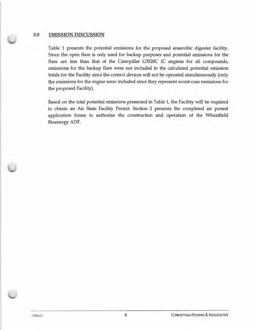
3.0 EMISSION DISCUSSION
77364 (1)
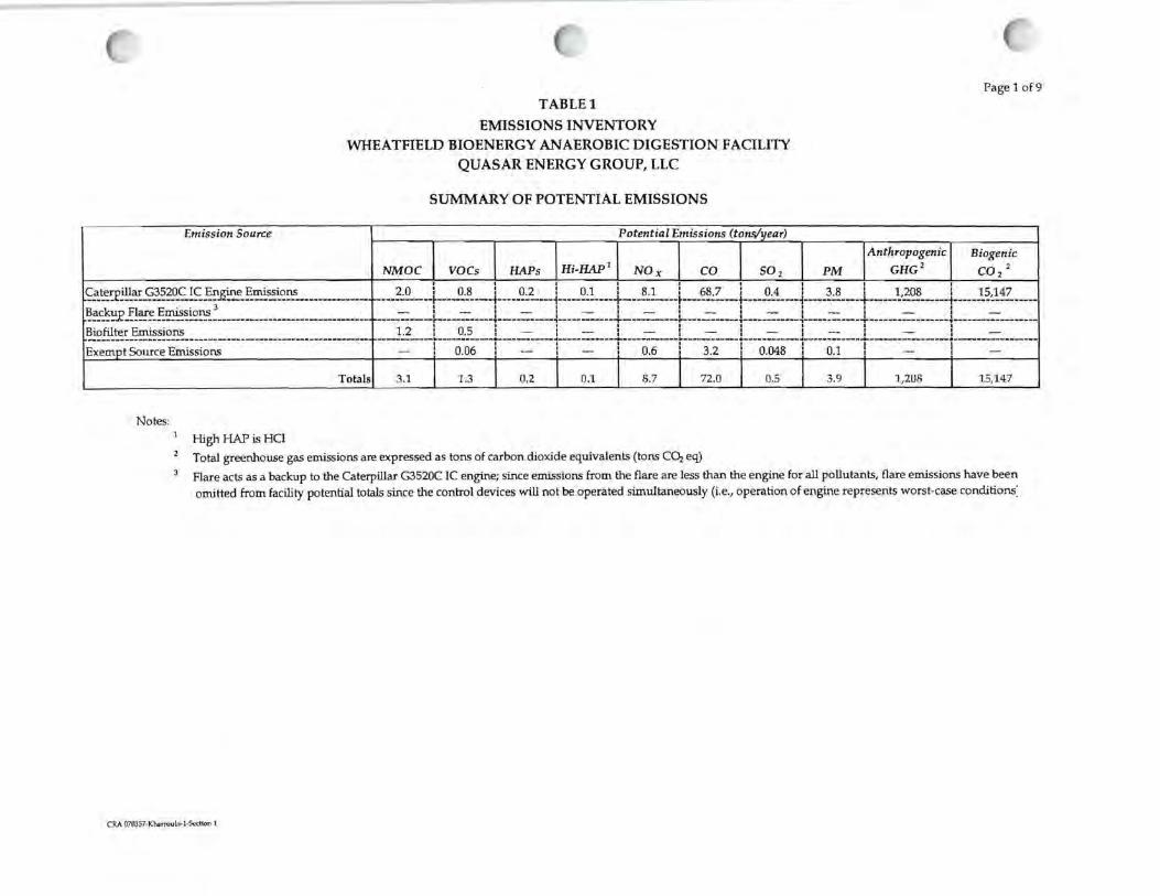
Table 1 presents the potential emissions for the proposed anaerobic digester facility.
Since the open flare is only used for backup purposes and potential emissions for the
flare are less than that of the Caterpillar G3520C IC engines for all compounds,
emissions for the backup flare were not included in the calculated potential emission
totals for the Facility since the control devices will not be operated simultaneously (only
the emissions for the engine were included since they represent worst-case emissions for
the proposed Facility).
Based on the total potential emissions presented in Table 1, the Facility will be required
to obtain an Air State Facility Permit. Section 2 presents the completed air permit
application forms to authorize the construction and operation of the Wheatfield
Bioenergy ADF.
6 CONESTOGA-ROVERS & ASSOCIATES
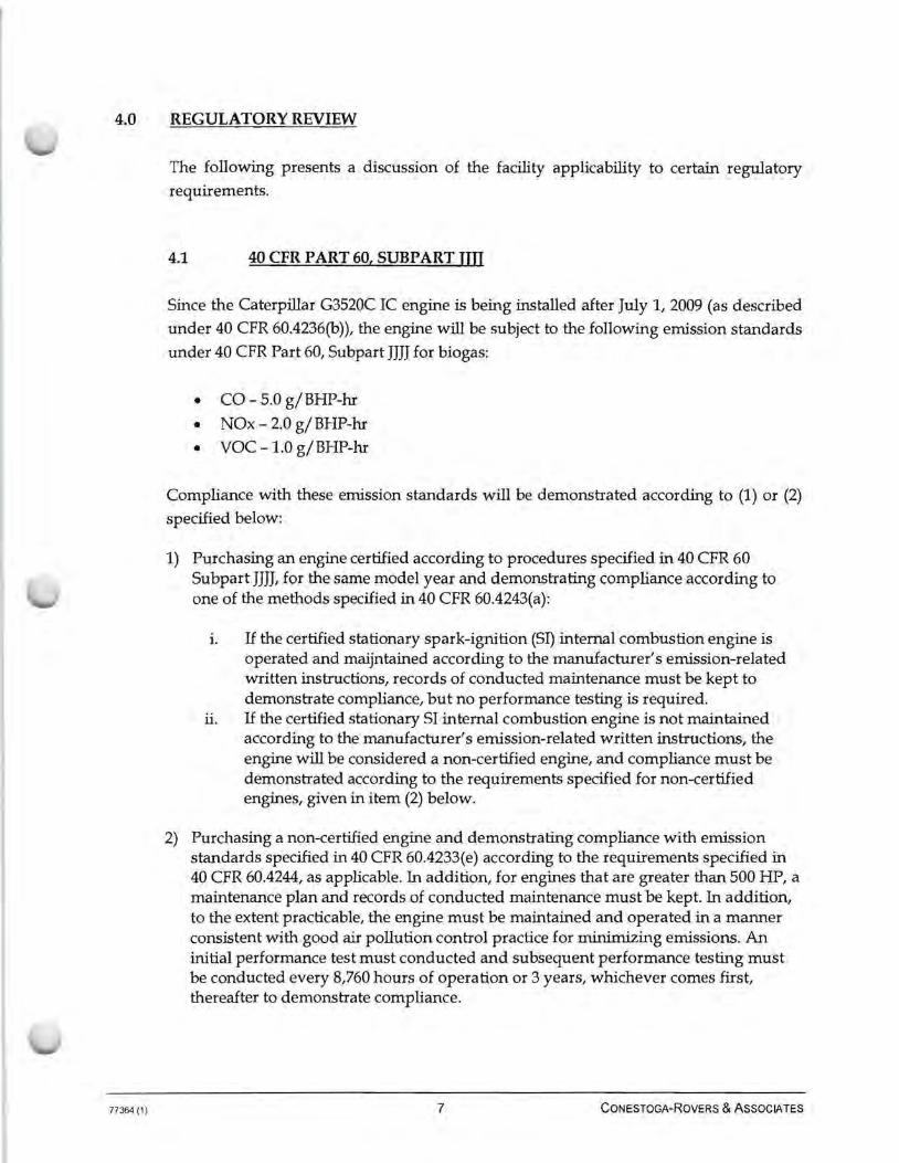
4.0 REGULATORY REVIEW
77364 (1 )
The following presents a discussion of the facility applicability to certain regulatory
requirements.
4.1 40 CFR PART 60, SUBPART UTT
Since the Caterpillar G3520C IC engine is being installed after July 1, 2009 (as described
under 40 CFR 60.4236(b)), the engine will be subject to the following emission standards
under 40 CFR Part 60, Subpart JJJJ for biogas:
• CO - 5.0 g/BHP-hr
• NOx - 2.0 g/BHP-hr
• voe -1.0 g/BHP-hr
Compliance with these emission standards will be demonstrated according to (1) or (2)
specified below:
1) Purchasing an engine certified according to procedures specified in 40 CFR 60 Subpart JJJJ, for the same model year and demonstrating compliance according to one of the methods specified in 40 CFR 60.4243(a):
i. Uthe certified stationary spark-ignition (SI) internal combustion engine is operated and maijntained according to the manufacturer's emission-related written instructions, records of conducted maintenance must be kept to demonstrate compliance, but no performance testing is required.
ii. Uthe certified stationary SI internal combustion engine is not maintained according to the manufacturer's emission-related written instructions, the engine will be considered a non-certified engine, and compliance must be demonstrated according to the requirements specified for non-certified engines, given in item (2) below.
2) Purchasing a non-certified engine and demonstrating compliance with emission standards specified in 40 CFR 60.4233(e) according to the requirements specified in 40 CFR 60.4244, as applicable. In addition, for engines that are greater than 500 HP, a maintenance plan and records of conducted maintenance must be kept. In addition, to the extent practicable, the engine must be maintained and operated in a manner consistent with good air pollution control practice for minimizing emissions. An initial performance test must conducted and subsequent performance testing must be conducted every 8,760 hours of operation or 3 years, whichever comes first, thereafter to demonstrate compliance.
7 CONESTOGA-ROVERS & ASSOCIATES
77364 (1)
The Facility will also be required to submit an initial notification to USEPA containing
the following information:
1. Name and address of the owner or operator 2. The address of the affected source 3. Engine information including make, model, engine family, serial number, model
year, maximum engine power, and engine displacement 4. Emission control equipment 5. Fuel used
4.2 40 CFR PART 63, SUBPART ZZZZ
Owners and operators of new and reconstructed stationary engines located at area
sources of HAPs emissions (total HAPs < 25 TPY and all individual speciated HAPs < 10
TPY) must meet the requirements of 40 CFR Part 60, Subpart JJJJ. If the engines are in
compliance with 40 CFR Part 60, Subpart JJJJ, then they are also in compliance with 40
CFR Part 63, Subpart ZZZZ.
8 CONESTOGA- R OVERS & ASSOCIATES
TABLEl
EMISSIONS INVENTORY
Page 1 of 9
WHEATFIELD BIOENERGY ANAEROBIC DIGESTION FACILITY QUASAR ENERGY GROUP, LLC
Emission Source
_<.;.::.~~'1'~-~-~~~~S..!~~~_&n_!_~~~-~~------------_l?~_c;_~~X!~.7-~~~~~~-----------------------------Biofilter Emissions
Exemot Source Emissions
Totals
Notes:
High HAP is HCl
NMDC
SUMMARY OF POTENTIAL EMISSIONS
Potential Emissions (tons/11ear)
voes HAPs Hi-HAP 1 NOx co 502 PM
Anthropogenic
GHG 2
I I I -- .-- - -- I I ---, I I
Biogenic
C0 2 2
2.0 : 0.8 : 0.2 : 0.1 : 8.1 : 68.7 : 0.4 : 3.8 : 1,208 : 15,147 ·------------~----------t-----------i------------+-----------~------------t------------i------------+--------------i------------------
1 I I I I I I I I I - I - I - I - I - I - I - I - I -I I I I I I I I I ·----------r-----------T-----00-----.,--·--------"'T'----------r00
---------... -----------.,------------"'T"----------------,-----------------1 I I I I I I I I
, ___ !2 ...... -t ........ ~.:~----1-...... ..::-.......... J .......... =---l------=-----L-----=---! .......... ::-.......... J .......... =: ........ l .. ----=------l-------=--------1 I I I I I I I I , 0.06 I - : - : 0.6 I 3.2 : 0.048 : 0.1 , - ,
3.1 1.3 0.2 0.1 8.7 72.0 0.5 3.9 1,208 15,14.7
Total greenhouse gas emissions are expressed as tons of carbon dioxide equivalents (tons COi eq)
Flare acts as a backup to the Caterpillar G3520C IC engine; since emissions from the flare are less than the engine for all pollutants, flare emissions have been omitted from facility potential totals since the control devices will not be operated simultaneously (i.e., operation of engine represents worst-case conditions:
CRA 07C057-Khi:t.n-oub._l ·SccHon 1
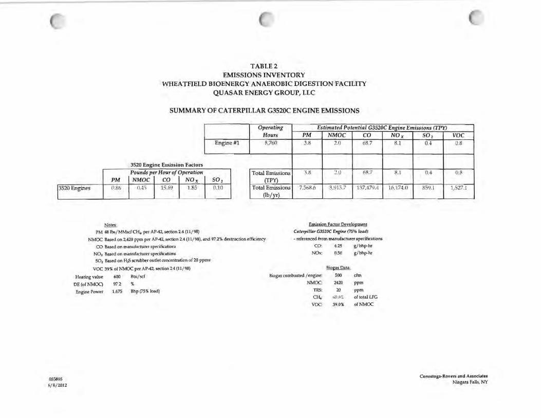
TABLE2 EMISSIONS INVENTORY
WHEATFIELD BIOENERGY ANAEROBIC DIGESTION FACILITY QUASAR ENERGY GROUP, LLC
SUMMARY OF CATERPILLAR G3520C ENGINE EMISSIONS
Operating Estimated Potential G3520C EnKine Emissions ([PY)
3520 Engines
Engine #1
3520 Engine Emission Factors
0.4) 15.69 ~ 0 0.86 1.85
Pounds per Hour of Operation PM I NMOC I co I NO x
Notes:
PM 48 lbs/ MMsdCH.., per AP-42, section 2.4 (11/ 98)
Hours 8,160
Total Emissions (fPY)
Total Emissions (lb/ yr)
NMCX: Based on 2,420 ppm per AP-42, section 2.4 (11/ 98), and 97.2% destruction efficiency
CO Based on manufacturer specifications
NOx Based on manufacturer specilications
502 Based on H,S scrubber outlet concentration of 20 ppmv
voe 39% of NMCX: per AP-42, section 24 (11/ 98)
PM NMDC co 3.8 2.0 68.7
'.).8 ~.ll 68.7
7,568.6 3,':J l.3.7 137,479.4
Emission Factor Development
Caterpillar G3520C Engine (75% load)
- referenced from manufacturer specifications
CO: 4.25 g/ bhp-hr
NOx: 0.50 g/ bhp-hr
Biogas Data:
Heating value 600 Btu/ scf Biogas combusted / engine: 500 dm
055805 6/8/ 2012
DE (of NMOC) 97.2 %
Engine Power 1,675 Bhp (75% load)
NMCX::
TRS:
CH,:
VCX::
2420 ppm
20 ppm
tin . o ·;~ of total LFG
39.0% ofNMCX:
NOx 8.J.
8.1
l(,,l/~ 0
50 2 voe 0.4 0.8
0.4 0.8
859.I 1,527.l
Conestoga-Rovers and Associates Niagara Falls, NY

TABLE2A EMISSIONS INVENTORY
WHEATFIELD BIOENERGY ANAEROBIC DIGESTION FACILITY QUASAR ENERGY GROUP, LLC
SUMMARY OF CATERPILLAR G3520C ENGINE HAP EMISSIONS
Biogas Engine- HAP Emission Esh'mates Total LFG Collected to Engine 1 = 5!10 elm
Hours of Operation= 8.7<>0 Uncontrolled Emissions
CAS ii LFG Constituent Molecular Median1 Avg.
Weight L'\3.41
'167.85 98.97 %.9.!,
"8.% !12."9 53.06
ppmv
ll.168 0.01}5 0.7-tl n.on ll.12(1
(I 023 u.0::.1)
ll.221 0.(107
(118'.l
0.227 0.-1-11' 0.010 (1. l ')i)
U•IB
3.395 fr789
lHJ03 2.0i:~
lb/hr (1.()(12
\)000 o.nor, (1,[)(rJ
o.on1 O.Ot){l 0.lJOU (l.ll(l!
0.(10(1
O.ilOl ll.!102 \J.002 0.()\)(1
0.00·1 0.010 0.(12~
o.n5s (1,000
ll.Oli 0.(1011
ll.ll06 11.0:JC, O.llll7 0.ll(X\ 0.1'.-\5 0.(1\)(,
0.17l) (1.U'.!6
lb/yr J .iO~
(1.::;.;
'l'J.18 5.98 7.9o ·1.71
u.~
lUg ll,;11 7..\7 17.P ·10.:->ll l).8(1
•l.<iO
TPY
o.rn 0.(lll
0.ll2 0.()0
0.0ll 0.00 ll.IJ(I
ll.D1 0.(10
il.llO ll.01 0.(11
ll.00 lJ.\){l
007 o.rn n2.1 ll.00 0.(11)
n.uo ll.03 0.07 ll.O.l ll.llc 0.5~
(1(13
fl .78 ll. 1.2
mg/m3 Control 6
71-55-6 1,1,1-Trichloroethane 79-34-5 1,1,2,2-Tetrachloroethane 75-34-3 1,1-Dichloroethane 75-35-4 1,1-Dichloroethene
107-06-2 1,2-0ichloroethane 78-87-5 1,2-Dichloropropane
107 -13-1 Acryloni trile 75-15-0 Carbon disulfide 56-23-5 Carbon tetrachloride
463-58-1 Carbonyl sulfide 108-90-7 Otlorobenzene 75-00-3 Otloroethane 67-66-3 Otloroform 74-87-3 Otloromethane '
106-46-7 Dichlorobenzene 75-09-2 Dichloromethane 100-41-4 Ethylbenzene 106-93-4 Ethylene dibromide 1
110-54-3 Hexane 7439-97-6 Mercury' 108-10-1 Methyl isobutyl ketone 127-18-4 Perchloroethylene 7'>-01-6 Trichloroethene 75-01-4 Vinyl chloride
1330-20-7 Xylene 71-43-2 Benzene'
108-88-3 Toluene' 7647-01-0 Hydrogen Otloride •
Notes:
Total HAPs
.hl.81 60.()7
11256
6•1.52 119.39
50.·1° 147.l)O IH.9(1
l(l().16
187.88 86. rn
2(10.61
lllO.lri '!.65.83 nuo 6~ . .'.-0
lil(>.16
78.ll 92.13 36.'l(>
O.fi0\1292 07SO 1.193 0.681 ·1.0?7
16.:>l:l2 0.97'~
25.·I0.5 9.'13
Concentration of incLividual HAPs were taken from Waste lndustry Air Coalition (WIAO
1-12.7·1 1933;' .J:H$.00
(J ,(\3
ll ~.22
ll.O·l J\l.37 l 32.o6 611.lll .1:;.1 .;
LJ.80.44 5(1.91.
1,5(11.J.52 ~30.5(1
2.20
Not designated as a HAP in 0.aptcr 2 4 o( AP-42 (11/~), but is listed in the USEPA National Emission lnvenlory (NEI) dalabase
No WIACconcentration specified for mercury; used AP-42 value
Used 'No or unknown co-d.i.sposal' concentration
HCI Concentration was taken from •Measu rement of Toxic Emissions from LandfiU: History and Cun-ent Developments•.
ContrOI efficiency of 98% assumed for all individuaJ speciated HAPs (except for mercury and hydrogen chloride)
~
(mglmi·~~-'-(M_o_lecu~lv~w_e~igh~t~)x_(~l-•l_m~)-•~(M_ed~ian_,_pp~m-v~)~~(298.15 K) x (0Jl8206 L'atm/ K•mol)
(lb/hr) • ____ (._m~g/~m_'J_x _(2_.20S_x_1_o~~Db_/_m~g._Jl_x _(L_F_G_C_om.--bu7st_io_n_r•_t_e [._It_' /_nun_·~)._) x_( __ ro_nun_._/_h __ r) _ _ _ ____ _
(35.3147 11' I mi
0b/yr) • 0b/ hr) x (8,7(,() hours/yr)
(fPY) • ________ (_lb--/y~r._) ------(2.0Cll lb/ton)
(ControUed Emissions)• (UncontroUed Emissions) x (100% • Average Control (%))
CR.A 0'7IDS7-KN.rroubi· 1·S..<" lio.>n l
O.~~ CJB.O~
l).Q'.\ %.O'!'"
3.ilO 'l~ .0%
ll . .36 98.0'.'.; tU,9 98.(1 ~;
0.11 Yl:H1% (l.1)6 08.0'X·
0.69 98.0%
0.01J 9~.0%
0.45 'l;l.0'.> l .lH '18.0% 1.18 %.(1'!;,
CJ.(15 "18.ll'• 0.26 OS.ll'.i'-H.7n 9$.(l~·.
11 .79 9RO% ~~.-16 98.01.:f. O.ll4 96.o~·.
7.27 %.(I~"
O.ilO ll.O'.\', 'l.ll/ 98.0':·., 809 98. o~·.
j.66 Y8.ll~-t.
2.75 ~8.0~\'.
71.95 98.0'7~
3.llJ 9~.0%
93.(17 98 .U'.~
14.05 0(1%
Page 3 of 9
Controlled Emissions
lb/hr (l,()()[)
ll.lJM 0.0l)(I (Ul(J()
n.ooo ll.DOO 0.(l<J(I
0.00ll
U,000 0.0llO 0.000 ().0(10
OJJOO 0.(li)(I
n O(ll)
l!.0(10
0.001 0.000 t!.l)(IO
0.00(1 lUlOO .1 .00l)
0.[)l)(l
0.(1\)(1
0.003 Ll.OllO 0.0lJ.l 0.1126
lb/yr ll..'ill 0.(11
ii .~~
ll.12 O.lb
0.ll3
om l).23
O.ol n.1s tU•I 0.39 0.tl'.! 0.09 2.115 3.87 9.67 ll.01 2.'>13 i1.0.1 1.01 )J•5 1.20 ll.~ll
2'.61 1.(12
'.\J.'\~
210.~~)
TPY
0.0(1
ll.00 0.00 ll00 ll.Oll (J (10
(1.()0
0.0(1
0.(10 (100 (1.0ll
ll.Otl . 0.00
(l.IJO 0.00 0.(10 0.00 OJIO O.Ol! o no (l.(J(l
ll Qi)
0.(10 (l.l)0
0.01 0.00 (1112
l~. l ~
0 ! (•

TABLE2B EMISSIONS INVENTORY
WHEATFIELD BIOENERGY ANAEROBIC DIGESTION FACILITY QUASAR ENERGY GROUP, LLC
SUMMARY OF CATERPILLAR G3520C ENGINE GREENHOUSE GAS EMISSIONS
Total Number of 3520 Engines = Biogas to Caterpillar 3520 Engine= SPO cfm
3520 Engine Combustion Factors Pounds per Hour of Operation
co2 I en. I N2o
Engine #1
Operating Hours
8,760
Total Emissions I (TP:!}
Estimated Pountial G3520C Ensrine Emissions (TPY)
Combustion I Combustion I Combustion I Escape I Collected I Biogenic C0 2 CH4 N 20 CH4 C0 2 C02
9,050.3 I 0.6 I U.l I 55.4 I G,097.U I 15,147.3
9,050.3 I (1.6 I 0.1 I 55.4 I h,0~7.0 I 1 5,'J.17.~ I 3520 Engines 2,06E..J I 0:1 I om Total Emissions I l..81 E+!l7 I l.1.IE+03 I '.!.19E+U2 I nn,719.7 I 1.22E+Q7 I :i .u::.E~o7 I
(lb/ yr)
Notes:
Combustion C01 Combustion emission factor referenced from Table C-1 of40 CFR Part 98, Subpart C
Combustion CH 4 Combustion emission factor referenced from Table C-2 of 40 CFR Part 98, Subpart C
Combustion N10 Combustion emission faclor referenced from Table C-2 of 40 CFR Part 98, Subpart C
Escape CH4 Collected methane that escapes destruction in engines (1 .66% of methitne processed)
Collected CO,. Portion of collected biogas that already containsC01 (45~ of collected LFG)
Biogenic C01 Sum of Combustion C01 and Collected COz
Anthropogenic GHG Swn of Combustion CH., Combustion N10, and Escape CH, expressed as
tons of CD1 equivalents
1,675
600
60
Bhp
Btu/ sci
"
Emission Factor Development
Cattrpillar G3520C Engine
Ef GWP
(kg/ MMBtu)
co, 52.07
CH, 3.20£-03
N20 6.30£-04
illil2fil;
(100 year)
1
21
310
Heat Input 18.0 MMBtu/ h r
LfG combusted / engine: 500 elm Engine Powe r
Heating value
LFG CH, Concentration
CH~ Destruction Efficiency
CH, Density
C01 concentration
C02 density
98.34 % (based on results of engine source tests; information gathered by the SoUd Waste Industry for Climate Solutions (SWICS))
0.0423 pounds per cubic foot (referenced from 40 CFR Part 98, Subpart HH)
40 " 0.116 pounds per cubic foot
Antliropogenic GHG
1,208.2
1,208.2
~.41E·t-U6
070094 6/8/2012
Conestoga·Roven ilftd ABsociate!il Niagara Falls, NY

TABLE3 EMISSIONS INVENTORY
WHEATFIELD BIOENERGY ANAEROBIC DIGESTION FACILITY QUASAR ENERGY GROUP, LLC
SUMMARY OF BACKUP FLARE EMISSIONS
Flare Type Operating Conditions Estimated Potential Flare Emissions (TPY)
Total Biogas Combusted= Biogas to Backup Flare=
500 cfm 500 cfm
Backup Flare
Backup Flare
Notes:
Flare Emission Factors :Feet Pounds per Million Standard Cubic
PM I NMOC I co I NO x S0 2
10.20 I 10.64 I 22200 I 4.0.80 3.27
Backup nare emission factors were derived based on the foUowing:
PM 17 lbs/ MMscfCH., per AP-42, section 2.4 (11/ 98)
CFM MMSCF Hours 500 262.8 S,160
Total Emissions (fPY)
Total Emissions (lb/yr)
NMOC Based on 2,420 ppm per AP-4.2, section 2.4 (11/ 98), and 98% destruction efficiency
CO Based on emission rate of 0.37 lb/MMlltu per AP-4.2. section 13.5 (09/91)
NOx Based on emission rate of 0.068 lb/ MMlltu per AP-42, section 13.5 (09/91)
502 Based on H,S scrubber ouUet concentration of 20 ppmv
VOC 39% of NMOC per AP-4.2, section 2.4 (11/98)
Heat Value 600 Btu/ scf
CRA 0703S7·Kh-.rnhit-it.t .St-c1k>n 1
PM NMDC co NOx S0 2 l.3 l..+ 29.2 5.4 0.4
1.3 1.4 29.2 SA OA
2,6S0.6 2,797.0 58,341.6 UJ,722.2 S59.l
Emission Factor Development
Bnckul! Fin"'
CO: 22200 Ib/ MMscf
NOx: 40.80 lb/ MMscf
Biozas Dal;!:
NMOC: 2420 p pm
TRS: 20 ppm
Gi,: 60.0% of total LFG
voe: 39.0% ofNMOC
DE(ofNMOC) 98.0 %
Page s of9
voe" O.::>
OS
J,090.S

TABLE3A EMISSIONS INVENTORY
WHEATFIELD BIOENERGY ANAEROBIC DIGESTION FACILITY QUASAR ENERGY GROUP, LLC
SUMMARY OF BACKUP FLARE HAP EMISSIONS
Riogas Flare - HAP Emission Estimates Total LFG Collected to Backup Flare=
Hours of Operation= 500 dm
8,760
CAS # LFG Constituent Molecular Median'
71-55-{i 1,1,1-Trichloroethane 79-34-5 1,1,2,2-Tetrachloroethane 75-34-3 1,1-Dichloroethane 75-35-4 1,1-Dichloroethene
107-06-2 1,2-Dichloroethane 78-87-5 1,2-Dichloropropane 107-13-1 Acrylonitrile 75-15--0 Carbon disulfide 56-23-5 Carbon tetrachloride 463-58-1 Carbonyl sulfide 108-90-7 Otlorobenzene 75--00-3 Otloroethane 67-{;6-3 Otloroform 74-87-3 Otloromethane '
106-46-7 Dichlorobenzene 75--09-2 Dichlorome thane 100-41-4 Ethylbenzene 106-93-4 Ethylene dibromide' 110-54-3 Hexane 7439-97-6 Mercury ' 108-10-1 Methyl isobutyl ketone 127-18-4 Perchloroethylene 79--01-{i Trichloroethene 75-01-4 Vinyl chloride
1330-20-7 Xylene 71-43-2 Benzene 4
108-88-3 Toluene • 7647-01--0 H ydrogen Otloride ,
Notes:
Total HAPs
Weight
133 . .J l l<:i7.H5 98.97
96 .~4
o~.%
112.99 53.06 76.1~
'15.'.8·1 60.07
11 2.50 6'!.52
119.39 50.4~
147.0D
M.'l<.! !(l(J.16
187.88 &i . l~
200.61 100.'lci 165.83 13!.40 (J2.50
Hl6.16 78.ll 92.1.I j (..'16
ppmv tl.l.68 0.(11)5 (l.7-ll
0.092 il.120 0.023 {J.()3~
\).221 0 (107 0.18:1 0.2~7
o .. ; 1~ 0.010 ll.l :•IJ l ..1,1JS
3395 ().789 tl.005 2.0;,<;
0.(1()0292 0.750
l.J.% lU18'l ·1.077 16.582 0.9'7~
25.105 9.<JS
Uncontrolled Emissions
lb/hr ll .002 0.000 O.il0(1 {l.UOl
0.001 O.llOll (U )Q{)
O.tlO I o.ouo O.P01 (l,l!ll2
U.002 0.000 O.!!O'l il .016
U.022 0.P'JS ll .OOtl tl.01 ~
o.r1on (l,()(16
0.015 0.007 0.008 o.n5 0.{ll)(< 0.179
ll,tlZ6
lb/yr
15 <r< (1.: .,;
" 'J. 18 !;.98 7.9o
l.7·1 1.2.'l
1'1:28 (l.T'!
7.37 17.J'.' ·1°.3H 0.8ll
'L6H l -12 7,1
J<J:l.37
183:10 O/<~
H 9.22 tl .O·l
5uJ7 132.0(1 (10.01 .1~>. J .1
1,180 . .J.1 '>0.91
1,569.52 2:l{l.fi6
TPY (l.()j
0.00 P.02 tUJO 0.00
0 00 0.00 ll.01 0.(10 il .00 U.01 0.01 (l .00 0.0(1
0.07 ll.'10 P.2·1 il.00 0.(li)
0.ou U.IF
0.07 ll.O:l IJ.IJ'.2 il.39 ll.113 n.78 tl.l1
2.20
Concentration of individual HAPs were taken from Waste Industry Air CoaUtion (WIAQ
mym3 O.'i'.2 l].0'.\ 3.(10 {l.3(,
0.49 0.11 0.06 0.69
0.0'1 0.13 'Utt 1.18 0.05 0.26 H.7Cl
U .79 '.'<l.-16 O.\M 7.Ll
o.no '\.tl7 8 09
~.75
71.95 .uo
CJ'J.67
H .ll5
Not designated as a HAP ill Chapter 2.4 of AP-42 (11 /98), but is listed ill the USEPA National Emission Inventory {NEI) database
No WIAC concentration specified for mercury; used AP-42 value
~
Used 'No or unknown cCHii.sposal' concentration
HCI Concentration was tabn from •Measu rement of Toxic Emissions from Landfill: History and Current Developments•.
Control efficiency or 98% assumed for a u indiv idual speciared HAPs (except fo r mercu ry and h yd rogen c h lo ride)
(mg/m~ -~---'{M_ol_eru_lu_w_ei~gh_t~) x-'-(l_a_tm-')_x-'(M_ed_i_an~p~p_m_v~) __ _ (298.15 K) x (0.08206 L•atm/ K•mol)
Ob/ hr) • ____ _,{m=g/c:m;.c.~.:.,;;..x .:..l2_.205_ x_l_;O_"'_,,[l_;b/'-mg-"'J'-) x_ (L:_FG_;:C_om.--bu,s_tio_n_;r_ate_,_[fl_':_/mrn_ · .:;))_x_,(60_mrn_._/:...h_r:_) ----- - --(35.J147 ft3 /m~
Ob/ yr) • Ob/ hr) x (8,760 hours/yr)
(fPY) • _ _____ ('-lb~/'-yr~) - - - - - -(2,CXXJ lb/ ton)
{Controlled Emissions) • (Uncontrolled Emissions) x (1001:. • Average Control [l:.])
Avg.
Control 6
90. f.1~·,
98{1~,
98.0% 98.0'.\·, 9$ (1~,
'.l8tl ''<~8.0 ~·1.
98.r.i~·)
91:-U)%
98.0 '.• % .O';,; 98.(1 ~,
':18.0"~
9:i .0~1"
%. (l~,
98.0~;,.
~!l.0%
98.0'!';, 9$.{J~,
n.o·x, 98.0'.•.', 98.n·:,, 93.0% q!l.O'." 90 .0';';'>
91:<.0% ~8 .0%
O.ll'!•
Page 6 of 9
Controlled Emissions
lb/hr O.OOtl U.000 0. 00(1 (l, (l(J()
il.lJ{h1
0.000 0.{IO(I (l.OOtl
0.000 0.00(1 O.llOll il.GOO \).(Ji)(l
0.(10{1
P.OOtl 0.0\lO O.OOJ 0.00\) D.!XlO O.UOO 0 .(\()()
il .OPtl O.OtKi 0.(lOP {l .00'.~
0.000 O.GtJ.I ll.ll26
lb/yr tl.3t) 0 (IJ 0.9~
!).J.2
0.16
ll.tl3 0.0'.'· tl .n {l.())
ll l3 u.:J.J 0.39 {l.02
0.09 2.85 3.87 9.67 u.rn 2.38 (l 04. 1.rn 2.r.3 l .20 il.9(1
2'.' .~l
1.02 :11.:v• '.!J0.3~
TPY lUJO 0.00 G.00 (l.(Jll
\)00
000 ll.llO O.Oll 0.00 O.llO (l 00
0.00 0.00 ll.00 0.00 O.llO 0.00 0.()(1
0.01)
(11)0
{l.O(l
ll.Oil
0.00 0.1)(1
0.01 0.00 0.02 (\.)2
O. l f,
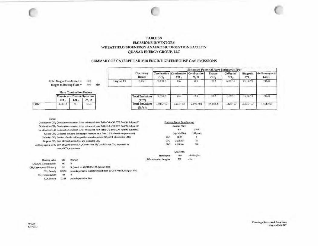
TABLE3B EMISSIONS INVENTORY
WHEATFIELD BIOENERGY ANAEROBIC DIGESTION FACILITY QUASAR ENERGY GROUP, LLC
SUMMARY OF CATERPILLAR 3520 ENGINE GREENHOUSE GAS EMISSIONS
Estimated Potential Flare Emissions (TPY)
Total Biogas Combusted= Biogas to Backup Flare =
5()0
5(1!1
Flare Combustion Factors
cfm
Operating Hours
Engme #1 8,71}{)
Pounds per Hour of Operation C02 I CH, I N20
Total Emissions (TPY)
Flare 2Jl66.3 I 0.1 I om Total Emissions Ob/vrl
Notes:
Combustion C02 Combustion emission factor referenced from Table C-1 of 40 CFR Pan 98, Subp.ut C
Combustion CH4 Combustion emission factor referenced from Table C-2 of 40 CFR Part 98, Subpart C
Combustion N20 Combustion emJ55ion factor referenced from Table C-2 of 40 CFR Part 98, Subpart C
Escape CH, Collected methane that escapes destruction in flare (1.0~ of methane processed)
Collected C02 Portion of collected biogas that already contains C02 (45% of collected LFG)
Biogenic C02 Sum of Combustion C02 and Collected C02
Anthropogenic C HG Sum of Combustion CH., Combustion NP. and Escape CH4 expressed as
tons of C02 equivalents
Combustion Combustion Combustion C02 CH, N20
9,050.3 0.6 il. l
l),050.3 O.fi 0.1
1.81 [,+!)7 1.llF.+03 2.'19E+tl2
Emission Factor Development
Backup Flare
EF GWP
(kg/ MMBfu) (100 year)
co, 5207
CH, 3.20E--03 21
N,O 6.JOE-04 310
~ Heat Input 18.0 MMBtu/ hr
Heating value
LFG CH4 Concentration
CH~ Destruction Efficiency
CH, Density
C02 concentration
CO, density
600 Bfu/ scf LFG combusted / engine: 500 cfm
070094
6/ 8/2012
60 ~
99 % (based on 40 CFR Part 98, Subpart HH)
0.0423 pounds per cubic foot (referenced from 40 C FR Part 98, Subpart HH)
40 %
0 .116 pounds per cubic foot
Escape Collected CH4 C0 2 33.3 6,097.il
33.3 f;,(197.0
61),698.6 1.22E+Q7
Bio genie An tliropogenic co, GHG
] J ,147.3 74.15.0
'1 5,147.~ 74(?.(I
3.0JE+ll7 l .19E•·06
Conrstoga-R.ovrn and Anocia.tn Niagara Falls, NY
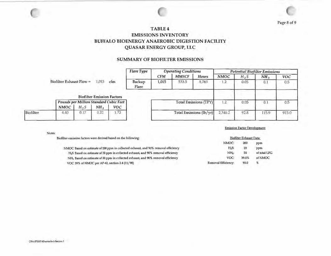
TABLE4 EMISSIONS INVENTORY
BUFFALO BIOENERGY ANAEROBIC DIGESTION FACILITY QUASAR ENERGY GROUP, LLC
SUMMARY OF BIOFILTER EMISSIONS
Page 8 of 9
Flare Type Operating Conditions Potential Biofilter Emissions
Bio filter
Biofilter Exhaust Flow= J ,O'J 5 cfm
Notes:
Biofilter Emission Factors Pounds per Million Standard Cubic Feet
NMDC I His I NH3 I voe 4.40 I 0.17 I 0.22 I 1.72
Backup Flare
Biofilter emission factors were derived based on the following:
CFM MMSCF Hours 1,015 533.5 8,760
Total Emissions (IPY)
Total Emissions (lb/yr)
NMDC H 2 5 NH 3
1.2 0.05 OJ
l.2 0.05 0.1
2,346.2 92.8 115.9
Emission Factor Development
Biofilter Exhaust Data:
NMOC: 200 ppm
H2S: 20 ppm
NHi: so of total LFG
VOC: 39.0% of NMOC
NMOC Based on estimate of 200 ppm in collected exhaust, and 90% removal efficiency
H:iS Based on estimate of 20 ppm in collected exhaust, and 90% removal efficiency
NH3 Based on estimate of SO ppm in collected exhaust, and 90% removal efficiency
VOC 39% of NMOC per AP-42, section 2.4 (11/ 98) Removal Efficiency: 90.0 %
CRA 070357-Kharroubi-1-Section 1
voe 0.5
0.5
915.0

CRA 070357-Kharroubi-J-Sectio n 1
TABLES EMISSIONS INVENTORY
WHEATFIELD BIOENERGY ANAEROBIC DIGESTION FACILITY QUASAR ENERGY GROUP, LLC
PM=
SOx .
NOx=
VOC=
CO=
SUMMARY OF BIOGAS BOILER EMISSIONS
10.20 lb. x MMSCF
3.27 lb. x MMSCF
40.80 lb. x MMSCF
4.15 lb. x MMSCF
222.0 lb. x MMSCF
Boiler Fuel Throughput
Biogas Heating Value
Maximum Gas Flowrate
Annual Biogas Combusted
Emission Calculations:
29.2 MMSCF BIOGAS =
29.2 MMSCF BIOGAS =
29.2 MMSCF BIOGAS =
29.2 MMSCF BIOGAS =
29.2 MMSCF BIOGAS =
2 MMBtu/hr
600 Btu/scf
3,333 scf I hr
29.2 MMscf
Lbs/yr Tons/yr 297.8 0.1
95.5 0.048
1,191-4 0.6
121.2 0.06
6,482.4 3.2
Page 9 of 9

ATTACHMENT 1
MANUFACTURER SPECIFICATIONS- CATERPILLAR G3520C INTERNAL COMBUSTION
ENGINE
77364 (1)
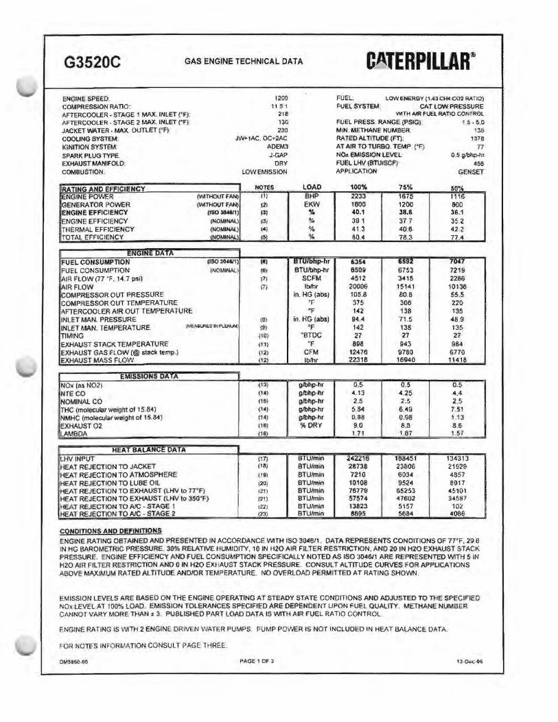
G3520C GAS l:.NGINE TECHNICAL DATA
ENGINE SPEE.D: COMPRESSION RATIO: AFTERCOOLER - STA.GE 1 MAX. ll'fLET CF): AFTER COOLER - STAGE 2 MAX. LNLET ('F) JACKET WATER · MAX. 00Tl£T {'F}" COOLING SYSTEM: IG.NITION SYSTEM: SPARK PLUG TYPE. EXHAUST MANIFO-lD: COM6USTl0tt
IRA TING ANO EFFICIENCY ENGlNE PO'NER GENERA'roR POWER ENGINE El'FICIENCY ENGlNE EFFICIENCY THERMAL EFFICIENCY 'fOTAl EFFICIENCY
t:N~••l\l·t= DA JI\
FUEL. CONSUMPTION FUEL CONSUMPTIQN IAIR FLOW (77 "F. 14.7 psi) !AIR FLOW !COMPRESSOR OUT PRESSURE COMPRESSOR OUT TEMPERATURE .A.FTERCOOLER AfR OUT TEMPERATURE INLET MAN. ~RESSURE
12{)0
11 .3:1 2rn 13-0 2.30
JW .. lAC. OC..-2'.AC
AOEMS J-GAP
ORY LOW EMISSION
(\MTHOIJT fAN)
l"WITHOOT f/JN) {IS0304&1}
CNOMINAl.;1 (NOMIJW..) tNOMINf.t\
OS03JJ-WI)
fNO.MINAI:. )
NOTES
t•l (6)
l7l (7)
(6)
INLET MAN. TEMPERATURE 'E~OltlPLEN.U (~)
TIMING { 10)
EXHAUST STACK TEMPERATURE i11)
EXHAUST GAS FLOW(@ &"!<'!Ck l!':mp . .J {12)
EXHAUST MASS FLOW f12)
EMISSIONS DATA
NOx (as N02) {13)
Nri;co {14)
NOMINAL CO ("1 5~
THC (molecular weight of 15.84) {14}
NMHC (molecular weight of 15.84) (14}
EXHAUST02 (16}
LAMBDA 11m
HEAT BALANCE DATA LHVINPUT (17)
1·1EAT REJECTION TO JACKET (111)
iHEAT REJECTIONTOATI.toSPHEf-{£ ( S) 1HEAT REJECTION TO LUSE Oil 1:w:1 HEAT REJECTION TO EXHAOS T (LHV to 1rF) fll) HEAT REJECTION TO EXHAUST (LHV lo 3-SG"F) (21)
HEAT REJECTION TO A1C - STAGE 1 (ll)
HEAT REJECTION TOA.IC - STAGE 2 f2"'.!i
CO~OITlONS AND OEFlNITIONS
LOAD BHP EKW
%
ti I UIDnp-hr BTU/bllp-tir
SCFM IM'lr
In.HG (abs) 'F •F
in. HG (absi "F
"BTDC 'F
CFM fblhr
g.lbhp-hr glbhp-llr glbhp-hr glbhp.hr gJbhp-hr %DRY
BTUfmin BTUtrnin BTUrmln BTU/min BTU/min ·STUfmin BTU/rr:tin BTUfmin
CATERPILLAR® FUEL LOW ENERGY (1 .43 CH4C02 RATIO}
i::uEl SYSlEM: CAT LOW PRESSURE v'>ITH Al!R FUU RATIO CONllWl
FUEL PRESS RANGE iPSIG) 1 5 • $,Q
MlN . METHANE NUMBER' 135 RA TEO ALTITUDE (fl); 137e AT A11'1 TO TURSO .. TEMP. ("Fr 77 NOJ1. EMISSION LEVEL 0 .. 5 g;'bhp-hr FUEL UN (BTUISCF) 11eo APPLICATION GENSET
100% 2233 1600 4-0.1 Ji! 1 41 .3 80.4
635-4 6509 4512
200(}6 llJ5.a 375 f<l.2 94A 142 27
aoo 1.2476 22318
o.s. 4.13 2.5 ~. 64
o.ae 9.0
1,71
242216 28736 7210 10108 76779 57514 13823 8895
75%
HF~ 1200 38.6. 37 7 -<'OJ~ 78.3
li~llZ
~753 3415 , 5'141 80.S 306 138 71 .5 138 27
943 9780 16-94-0
0.5 4.25 2.5
6 .49 0 .98 8 .8 1.67
1884:51 23f.l06 6:{}34
~524
65253 47602 5157 5684
50% 1ne; &10 36j 35.2 42 z 77.4
7047 7219 :?286 101~
55.5 220 135 48 .9 13.5 27
98.4 f,77-0 11418
o.5 4.4 2 r. . :.>
7 .51 113 8.6 1-57
134313 21929 4-%7 8917 45101 3-45117
102 40&6
ENGINE RA TING OBTAINED AND PRESENTED IN ACCORDANCf. ll'J1TH ISO 3045!1 DATA REPRESENTS CONDfflONS OF 77'F, 29 .. 6 IN 1-fG Bl~OMETRIC PRESSURE. 30% RELATIVE HUMIDITY. 10 IN H2-0 AIR FILTER RESTRICTION, ANO 20 IN H20 EXHAUSTS TACK PRESSURE. ENGINE EFFICIENCY AND FUEL CONSUMPTION SPECIFICALLY NOTED AS ISO 304&'1 ARE REPRESENTED WITH 5 IN H20 All'< FILTER RESTRICTION A.NO 0 lN H20 EXHAUST STACI< PRESSURE. CONSl,I T Al TlTUOE CURVES FOR APPLICATIONS ABOVE MAXIMUM RATEOALTITUDE.ANDIOR TEMPERATURE. NO OVERLOAD PEAMlifEO AT RATING SHOWN .
EMISSION LEVELS ARE BASED ON THE ENGINE OPERATING Ar STEADY STATE CONDITIONS AND ADJUSTED TO THE SPEClflcD NOx LEVEL ,C.T 100% LOAD. EMISSION TOLERANCES SPECIFIED ARE OEPENDtNT UPON FUEL QUAllTY. METHANE NUMBER CMINOT VARY MORE THAN ;r 3. PUBl.lSHEO PART LOAD DATA IS WITHAIR FUEL RATIO CONTROL.
ENGINE R/1TING IS WlTH 2 ENGIN DRt\IEN WA.TER PUMPS, PUMP POWER IS NOl INCLUDED IN HEAT 8AL1\NCE DATA.
FO<~ NOTfS INFORMATION CONSULT PAGE THREE.
PAGE1 OF J , J·-.0:'-0c-W

G3520C GAS ENGINE TECHNICAL DA TA CATERPILLAR~· .
1JO 0.96 O.ll3 CU!e 0_311 O.!l3 0. 79 0.711 0.7~ (Hl \MIO O.G5 0.63 0.6-0 120 0.98 O,IM 0,91 O_fil' ' 0.84 0.81 Q.78 0.7~ ~72 (),!}'# O.Gtl Oti4 0.61
AIR 110 0.99 0.9!l 0:112 o.aa 0.88 082. (),79 (>-76 o.n 0:1a 0 ,68 ·0.6S 0-62 TO 100 1.00 0.97 0.94 0.90 0.87 0.84 0,111 0-77 0<.74 0_72 UG 0.66 0.63
T\JR(IO 90 1.00 0,99 0.96 Q.92 0,89 0.85 on 0.79 0.76 0 73 0.10 U.67 065 ~o 1.00 1,00 0.97 0 .!M 0.90 0 IJY OM 0 .$0 0.17 o-7• o.:t1 0 .68 o.ee
("!') 70 1.00 l .00 099 0.96 092 06!i (}.85 o~ 0.711 0 .76 0.7!1 l'l.70 067 eo •.oo 1,0Q 1.()(1 097 0.94 0Ji¢ 0..81 •Jib 0.80 0.77 0.74 tH1 O.&I
50 1.00 1.00 1.00 0,')9 0.9<> ii.92 0.8& i:i.M 0.82 0.711 0.76 0 .73 0 .70 o 10i00 2000 JOOCJ 4000 sooo eooo 700tl 1000 tooo •oooo 11000 12000
ALn'iUCE EETABOIE &fut.~L
130 1.3:1 1.37 1.40 LAO 1.40 1.40 1.4-0 1AO 1,40 ""° 1.40 1.40 I.AO
120 1.28 1-31 1.:13 1.:IJ 1 .3~ 1,33 1.33 t.ll 1-33 1-33 f .33 1.33 1-3.l
A!R 110 1.19 1.:24 1.211 126 1.10 i 1.26 1 .~ 1 . .2i> 1.16 1.26 1.26 1.26 1.26
TO too 1,13 1.17 120 U<l 1.20 1 1.;l(l 1 .. 20 U!G 1.2.0 1.20 uo 1.20 120 TURBO 90 l.06 1.11 1.t3 1.13 1.13 1.13 1.13 1.13 U3 1.13 1.13 1.13 1.f3
80 ; ,(!() UM 1.00 1,00 1.00 1,06 LO!i 1.oe 1.!:e 1.QIS LOO l.OG 100 i'F) 70 i.oo 1,00 1,00 1.1.)(1 1.00 1.00 LOO 1.00 1 00 1.00 LOO l.00 ·i.oo
w 1.00 1.00 1,00 1.00 LOO 1.00 LOO 1.00 1.00 1.00 1.00 l.00 1.00
50 1.00 1.00 '1.00 1.00· 1.00 1.00 1.00 1.('.0 100 1.00 1.00 1 Oil HIO O 1000 :2000 3000 .000 6000 $-000 7000 ~OOQ tOOO 10000 11000 1200D
A\,TJTL.Oi' lfEET "itO':E SEA Ll?.IEl
FREE flELO IAECHAMICAL & EXHAUST NOISE I
1 OO'h LO<ld O~~ dB(A) !dBi
Cl~<A'Y:E "liOM 3.2 108.5 51-5 7ln ea.• 112.9 119.S- 97.3 93.2 00,2 'Free fl~1:.J
rHE B"'Gl' E 22,9 91.6 2-4.6 5€1.1J 68.1 7•.0 83J) 79.4 75 ,1 SS.2 M<!Ollanlcel ~ ~ · 11 49,2 85.0 21!.0 ~2 &4 .7 69.• 75.A T.UI 69.7 75.7
Oi!iT Niie£ F'RO•\ ..i,'9 100, I 67_5 lro , ~ 116.0 88,S 88.7 00.1 r.5 .6 02 7 Fmi Fi!Jld
l11 t:'. ~t: 22,9 Qt.1 ~u 13.1 82.6 75. 1 75.3 7'1.7 112.2 793 i:..i-...ust (<E i 0 .2 96.1 47 . .S 1:16.5 76.Ci 66.5 88.7 7o. l 7~ ,11 727
OY•IOlllSl'I.. Um US Hz 250 ttz 500 H:t 1 utt 211.Hz: ·H~ I '"-z ""'ave B..,d C'""""'- Fno..,.,.,cv fOOCFI
FY!il. USAQf au1pe ms·1Z:Ut shaw5.t!lfl ct.'lhtl'a®r r~ fur• 9'~W Nat_, lrtll ih!:~r:Jl'J .o-o:or>1 n~ tt".it"" ~ nl.ifnC.cril.,,...JUS.C:S.. ~ ~ lS '6 sea: · ta~•
d~hm1tt~~t:.~~ft'Cl;c.e:.'.lf._"3f"'.>e:VS ~els. TM mtrlharie number of a rt.iel~~dak:t:rm$<'~b<j U.$i'llq·1ita C•1t1p.llat M¥1h•n• ~rC~ ~m
f!Ll!rupg PWI19N fACJCIR§t TN~tW• P\tliwf ~ 0ttei1K..-1 i't!Quti•i: tGr ~ro!S ar- rJel Lttm~r._,...,.,,~ .utd illitwlns. Use: lr'.is ;11fai"!"Nt.IW\ 1 1~,il 'ii'~ •~ rt'.;• U\tl!lllJ !i~tnt! 00111n toc fl.~ a~eimanc ~ engM oa#Ot 1-.V)\':l.L ,,_o
INLET MJD EltHAUl9T R£5.TRICTIClN ¢(mRECD2lt' f0a~TIT~PA3JLIIT
fg dtUtnrrne lha: 1p.p~.au1ud11 dor.ite: t.a:.ta:r to ba~+d t" n w ...-l)n:; funiiWir.f :t:t::>l.lill ~M:&IDn :i. d~~M!:J ficm O'liil
.Y;;in.43i1'CA: t11lit..,,..t Vined oo p8oe ?1. 111 c.orr.eaJan lo H1I sne- 1 tu~c: o:..n bf~~•-Ci.UJI ~-... d .nc.., Ar.1d 1'4 1 ~totnt JAe
alitudc bf 11orcn ~111tn>1l .itch ar H~O O'f Q.:tdruM ••a~ pr .,.,.... gftf:ler t..~ ipo~ ishcr:t t ON.l'! WM'! J Add 'B:: ros~ h>tt. .. .a-'4i "'fo f Pf ...-.Jt n::kil~ 1nd; ot H20et1n"" .n:S1tklicn gr•:iu:it ttul.11 r;p,e,:·•hff': ~i\lillAf. n tfl'-' f"h'l l ""'tncilXm or exhauM .JUd. pre1~
>:1:ro lr::Js ~ ..,-..: ~ CCff:1011;;.«.., I.ti• eerne tl'l!lr'dJ 1pp~· 1.a ~Ir the--. Olft.£..tX.
ACJUAl ENON!;: RARllG·' "t15impcrtlrtt:Jn::eem~theA1J'fUO&lT~illwa tNJ Ute f\•ll'Mrilt'~ukic~lb> .M.t.fMA a.aftCll'h'C: Th.iy~ l'l("A r() -. ~~p!f'M!i!. li"te
"~"t• JJ tl'vt • 111• UJ•· Enof'gy ~~~.,,..mc:irt(1~..etrJ.ctC~trp1L;r "'~9~p,ll!i~ tH'l;; tne 'f we1 u~~ ·Ci\&4< c.aftklto . HOi11•¥t :. 1tw
AJUl.ai!!t."TomJicr.llLlMDWl1i:)!i .an-:l lO# fflf(CJI f...;/ ditOtJO'n d1~ cumuYcJw: M"Jd tl"d!"f mtnl l:a ~ lct;vtl-• «i in.""**'~ MJow . To. G~.:r-.-e
t..._ 111Cl11t1I ~ 11¥9l•b\lr. t:it» tne la•Ht r.:anno bat.tt11 l ) :w"id 2'·
1J (AtHe:uckl'l•tr.r•"*"l! l>.f•I~. ('LJ:JltJ Et'feqyFue:IOe:r.ltir:Y;)
;::.i r-'oetl.b.a;a GUiJlt~!IQn
~w For t1A'I lhrlr)"I j :J: J1 1t1e l..C"I\' ~ff.·~ Oie\TabOtl to ~ M~CIT¢dfir.ur11· a1n.M:Cn Fqir Toi. t'-' t~ t only :>j;J ()}r lailf Er~r~ FVd
S::l!f on ID !hi oli:aJ'tUiJlliT~lur'a iei.<1' l~lf1 Wt.11tttii"~ lhf' A:Utu~IT e-mpa~ do.r.1b~ ,(i flf'll tNl!: 1. 0 ~ 1 w.?'~ J ' Th i ~ wAI 'QIV1' !h t' IJat;.l lJ; ,.~.trQ
fl.~r u·~ «G1!1t! m 1he !X"-.::1.tu.m::; 'pctl1JH1,
11rJr??jCf''Q~ U~I ft£tJECil"N F'ACTO'R9;
.-.1'!!JC-OG'U~61l-il1}ir!MO la gi~~ & ~ti f;.-ontl tun1•ot'tr-F 1n:itt:>:i 1· .aflit.·..1~ T!.i rr.-hl.in ~ ~h•"' e tt ~""' N.l:a te~ie~c .. e\h11unutum-3'
ll"mpe~l\Jf""' 'P'-"~ up, 5D muio:: N -ftt!l ill'I n&Jotflcri A$ Mfha!h• ~f .. U t. Uh:t tu~h::i1.o;-:r •. 1.J/. • --CO. natd~ bl wwc.001 111 ltl• ht'"t ~'91"'~ pte:surt".
rrJ~ lncttM lh• arn.°"11~ 1 cl~ l1'fl'; ~ 1 t.~r~m,w'1ffom~·"re! !r!k1M'lt11 the al'l t Mb •~ti-.- n ~.ctort:o~ ""1~ 11.r1tl 11,,ilOdll ~lkwlt. J.Jdl~)' tiin l\Jl'Jlo:r bit lt!e 51.an:!ati:t 1n11r<:..:ic• hHI rljcv..JlGIJ F•U;.(li 't:io p o1hirly . t.n....-.mt J.1.1111 l l"t~ !ill.t"i'Ott o:.UC 1.e..wit ,, cal+~ ll.M
t.:iill;1t''lhe c.nprlf'l·.:. Jtii.ild~-n ,;(' l~ H F-::tt 2 S IA9" "'~"1Ct>Oblr•, .,,, .. :h ll~:e: t=<t'>:11r.s .. 11t~ ~$ Slll{;ll . , . cotm ~ .. ll f I~ 1t()i() fl r'l-i , ~ ·
';;QU N!!Q!IAJ
Uzila dc.rteurru11 ed b¥ ~iex:fistt•l~r IC ISO ~iJ C~f:4"S~10 H.w ac_y G~Oltl• :; , ·~P .... ,. :i.:i.iP.1l Fre:s~n.! ~ " ""''
OM!'.iBfiD..GC-

G3520C GAS ENGINE TECHNICAL DATA
1 ENGINE RATING IS WITH 2 ENGINE ORNEN WATER PUMPS. TOLERANCE IS ;t. 3% OF FULL LOAD.
2 GENERATOR POWER DETERMINED WITH AN ASSUMED GENER.ATOR EFFICIENCY OF 96.1% AND POWER FACTOR OF 0 .. 8 {G.ENERATOR POVVER"' ENmNE POWER :x. GENERATOR EFFICIENCY]
3 ISO 3046/l ENGINE EFFICl.ENCY TOLERANCE IS (+)0. {-)5% OF FUU LOAD% EFFICIENCY VALUE. NOMINAL ENGINE EFFICIENCY TOLERANCE IS -.t 2.5% OF FULL LOAD% EFFfCIENCY VAllJE
4 THERMAL EFflCIENCY: JAC:KET HEAT+- STAGE t NC HEAT+ EXH HEAT TO 35.Q'F.
5 TOTAL EFFICIENCY"' ENGINE EFF. +THERMAL E:FF TOLERANCE LS t: 10% OF FULL LOAD DATA
6 ISO 3046!1 FUEL CONSUMPTION TOLERANCE IS (+J5, {-)0% OF FULL LOAD DATA. NOMINAL FUEL CONSUMPTION TOLERANCE IS ::1: 2.5 % OF FULL LOAD DATA.
7 UNDRIED AIR FLOW TOLERANCE IS'± 5 %
6 INLET MANIFOLD PRESSURE TOLERANCE IS± 5 %
9 INLET MANIFOLD TEMPERATURE TOLERANCE IS± 9•p
10 TIMING INDICATED IS FOR USE WITH THE MINIMUM FUEL METHANE NUMBER SPECIFIED. CONSULT THE APPROPRIATE FUEL USAGE GUIDE FOR TtMING AT OTHER METHANE NUMBERS.
11 EXHAUST STACK TEMPERATURE TOLERANCE :1s (+)Q3•F, {-):54•F_
12 WET EXHAUST. FLOW TOLERANCE IS± 6 %
13 NOX TOLERANCES ARE~ 18 % OF SPECIFIED VALUE.
14 NTE CO, C02, THC, and NMHC VAUJESARE ~NOT TO EXCEED",
15 NOMINAL CO IS A NOMINAL VALUE AND IS REPRESENTATPl/E Of A NEW ENGINE DURING THE FIRST 100 HOURS OF ENGINE OPERATION.
16 02% TOLERANCE IS:± 0.5; LAMBDA. TOLERANCE IS± 0.05. LAMBDA AND 02 LEVEL ARE THE RESIJL T OF ADJUSTING nu~ ENGINE TO OPERATE AT THE SPECIFIED NOX lEVEL
17 LHV RA.TE TOLERANCE IS:!: 2.5% ..
1.8 TOTAL JW 'HEAT (based on treated wat@r) =JACKET HEAT+ STAGE 1 NC HEAT+ 0.90 X (STAGE 1-+ STAGE 2) x (ACHRF-H TOLERANCE IS~ 10 % OF FULL LOAD DATA
19 RADIATION HEAT RATE BASED ON TREATED WATER. TOLERANCE IS± 50% OF FULL LOAD DATA.
20 LUBE Oil HEAT RATE BASED ON TREATED WATER TOLERANCE IS± 20% OF FULL LOAD DATA.
21 EXHAUST HEAT RATE BASED ON TREATEDlNATER. TOLERANCE IS ;t l0% OF FULL LOAD DATA
22 STAGE 1 A/C HEA.T{ba.sed on treated water}= STAGE 1 AJC HEAT + 0.90 x {STAGE 1+STAGE2) x (ACHRF-1). TOLERANCE IS±: 5 % OF FULL LOAD DATA .
23 STAGE 2 AlC HEAT (b3$ed on treated water)= (STAGE 2.AJC HEAT+ (STAGE 1 +STAGE 2} x 0.10 x (ACHRF- 1)) + LUBE OIL HEAT TOLERANCE IS :t 5 % OF FULL tOAD DATA.
OMSBG0--00 PAGE:l OFl

SECTION2
AIR STATE FACILITY PERMIT APPLICATION FORMS
77364 (1)