critical appraisal of piping phenomena in earth dams8isi.com/pdf/omran/critical appraisal of piping...
TRANSCRIPT

ORIGINAL PAPER
Critical appraisal of piping phenomena in earth dams
Kevin S. Richards Æ Krishna R. Reddy
Received: 15 January 2006 Accepted: 18 May 2007 Published online: 7 July 2007
� Springer-Verlag 2007
Abstract This paper presents a comprehensive review of
published literature on soil piping phenomena. The first
tools to design earth dams to resist piping were developed
during 1910–1935. Filter criteria for dispersive soils was
refined in the 1970’s. Piping phenomena are generally
defined as: (1) heave, (2) internal erosion, (3) backwards
erosion, although other modes are possible. Recent work on
piping highlights the limitations of the occurrence of piping
and the role that design and construction may play in a
large percentage of piping failures. Standardized laboratory
procedures are available to assess piping potential in
cohesive materials, but no such methods exist for non-
cohesive soils. However, methods are available for evalu-
ation of self-filtration potential. Recent advances in com-
puter technology have facilitated the evaluation of seepage
and deformation in embankments but computational
methods for evaluation of piping potential are currently
limited.
Keywords Earth dams � Piping � Internal erosion �Heave � Suffosion
Resume L’article presente une analyse generale de
resultats publies sur les phenomenes de suffosion des sols.
Les premiers outils visant a dimensionner les barrages en
terre contre la suffosion ont ete developpes durant la
periode 1910–1935. Les criteres de filtres destines a eviter
ces phenomenes ont ete ameliores dans les annees 1970.
Les phenomenes de suffosion sont generalement associes a
(1) du gonflement, (2) de l‘erosion interne, (3) de l‘erosion
regressive, mais d’autres processus sont possibles. Des
travaux recents sur la suffosion mettent en lumiere les
techniques permettant de limiter les risques d’apparition de
ce phenomene. Ils montrent aussi le role des principes de
conception et des techniques de construction sur beaucoup
de situations de rupture initiees par des phenomenes de
suffosion. Des essais de laboratoire standardises existent
pour evaluer la susceptibilite a la suffosion de sols cohe-
rents, ce qui n’est pas le cas pour des sols non coherents.
Cependant, des methodes sont disponibles pour evaluer la
capacite d’auto-filtration d’un materiau donne. Des avan-
cees recentes dans le domaine de la simulation numerique
ont facilite l’evaluation des ecoulements et des deforma-
tions dans les structures de barrage en terre, mais il faut
noter que ces methodes numeriques restent impuissantes
pour mettre en evidence les conditions d’apparition de la
suffosion.
Mots cles Barrages en terre � Suffosion � Erosion interne �Gonflement
Introduction
Based on the history of earth dam failures in the nineteenth
and twentieth centuries, it is likely that piping failures in
dams have occurred since the earliest dams were con-
structed around 2900 BC. Early methods of construction did
not consider the effects of seepage or proper zonation of
materials to provide adequate filters in earth dams. As
experience grew with the successful construction of dams
on a variety of foundation materials, empirically successful
K. S. Richards (&) � K. R. Reddy
Department of Civil and Materials Engineering,
University of Illinois, 842 West Taylor Street,
Chicago, IL 60607, USA
e-mail: [email protected]
K. R. Reddy
e-mail: [email protected]
123
Bull Eng Geol Environ (2007) 66:381–402
DOI 10.1007/s10064-007-0095-0

dam designs emerged by the first millennium AD as evi-
denced by the 2,000 year service life of the Proserpina
Dam constructed by the Romans (Jansen 1983, p. 16).
Shortly after Henry Darcy (1856) recognized the relation-
ship between head, length of flow path and fluid velocities
in granular media, methods were developed to evaluate
piping potential from the length of flow path under dams
(Bligh 1910, 1911a, b, 1913; Lane 1934). With the advent
of modern soil mechanics, Terzaghi (1922, 1925) devel-
oped a method for the evaluation of heave. Methods were
also developed to aid in the design of defensive piping
measures in the form of filters (Terzaghi 1922, 1939, 1943;
Terzaghi and Peck 1948; Bertram 1940; Sherman 1953;
Sherard and Dunnigan 1989), and evaluation of hydraulic
gradients for design (Forcheimer 1886; Casagrande 1937;
Cedergren 1977). This paper provides a critical review of
piping literature and methods currently available for the
evaluation of piping- related problems in existing dams.
Definitions
Due to the large body of work that has been completed on
piping research, and the fact that the work is the product of
international and multi-discipline study, there are a number
of definitions in the literature regarding piping phenomena.
It has been common for practicing engineers to lump all
these definitions under the generic term ‘‘piping’’. This
practice makes it difficult to determine the root cause of
piping failures when researching case histories. For clarity,
definitions are necessary before proceeding with this review.
(a) Terzaghi (1939), Lane (1934), and Sherard et al.
(1963, p. 115) present a model of piping in which
particles are progressively dislodged from the soil
matrix through tractive forces produced by inter-
granular seeping water. The mobilizing tractive forces
are balanced by the shear resistance of grains, weight
of the soil particles and filtration. The erosive forces
are greatest where flow concentrates at an exit point
and once soil particles are removed by erosion the
magnitude of the erosive forces increases due to the
increased concentration of flow. This view of piping
is the classic backwards-erosion style of piping.
‘‘Backwards erosion’’ is generally produced where a
roof of competent soil or some other structure allows
the formation of a bridged opening. The tractive force
causing this type of erosion is directly proportional to
the velocity of intergranular flow. Lutz (1934) pre-
sented a model where the physico-chemical properties
of soils are the primary factor in soil erosion. In the
case of ‘‘backwards erosion’’ piping, resistance to
the removal of grains of soil is dependent on the
hydraulic gradient through the soil (which is required
to overcome this resistance) as well as the state of
stresses around the opening being formed by the
erosion of material.
(b) ‘‘Internal erosion’’ (as used here) is similar to back-
wards erosion piping in that tractive forces remove
soil particles. However, internal erosion is due to flow
along pre-existing openings such as cracks in cohe-
sive material or voids along a soil-structure contact.
By this definition, internal erosion is not due to the
dynamics of intergranular flow and the hydraulics of
the problem are quite different than for backwards
erosion (Lane 1934). Rather than being initiated by
Darcian flow at an exit point, internal erosion is ini-
tiated by erosive forces of water along a pre-existing
planar opening. Hence, it may be expected that
internal erosion would initiate in accordance with the
cubic law of flow for planar openings (Franco and
Bagtzoglou 2002; Louis 1969; Worman and Olafs-
dottir 1992). Internal erosion is expressed as a tractive
load along the length of the opening. This contrasts to
the case of backwards erosion, where the erosion is
occurring at the exit point. Due to the nature of
hydraulic conductivity at a soil-structure boundary,
fluid velocities may be more erosive for a given
hydraulic gradient due to higher velocity flows. Also,
as the hydraulic conductivity tends to be slightly
greater at a soil structure contact, this is often the first
place that increasing hydraulic gradients may express
themselves through erosion.
(c) ‘‘Tunneling’’ or ‘‘jugging’’ are common features ob-
served in dispersive soils caused by rainfall erosion
and is discussed by a number of Australian and New
Zealand workers (Jones 1981). Tunneling occurs
within the vadose zone and is due to chemical dis-
persion of clay soils from rainwater passing through
open cracks or natural conduits. By definition, tun-
neling does not occur in the phreatic zone. In extreme
cases, tunneling or jugging in dispersive soils can lead
to dam failures similar to the tunneling activities of
animals or penetration by tree roots.
(d) East European researchers coined the term ‘‘suffo-
sion’’ (Jones 1981; Burenkova 1993; Pavlov 1898;
Kral 1975; Galarowski 1976) to describe the gradual
migration of fine materials through a coarse matrix
leading to failure (McCook 2004; Kovaks 1981; Kral
1975; Galarowski 1976; amongst others). This pro-
cess can result in a loose framework of granular
material with relatively high seepage flows that leads
to collapse of the soil skeleton (McCook 2004). In
non-cohesive materials, suffosion leads to zones of
high permeability (and water transmission), potential
outbreaks of increased seepage, increased erosive
forces and potential collapse of the skeletal soil
382 K. S. Richards, K. R. Reddy
123
structure. Suffosion can be a much slower process
than is commonly observed where piping occurs
along a concentrated leak. Hence, suffosion may be
related to long-term seepage problems that exhibit
increasing seepage quantities over a period of years.
Gradual loss of finer matrix materials in a soil sup-
ported by a coarser grained skeleton is termed suf-
fusion, which may lead to a more general collapse
and loss of soil structure, termed suffosion (Kezdi
1979; McCook 2004).
(e) The phenomenon of ‘‘heave’’ was discussed by Karl
Terzaghi (1922, 1943), who developed an equation
for assessing heave in sheet pile cofferdams. As
reported by Terzaghi, heave occurs when a semi-
permeable barrier overlies a pervious zone under
relatively high fluid pressures. One significant aspect
of heave is if the fluid pressures in the pervious zone
increase, such as during a flood, a point may be
reached where the uplift at the base of the semi-per-
meable barrier exceeds the vertical effective stress of
the overlying barrier. This form of failure occurs at a
hydraulic boundary where the migration of water
through the barrier is at a slower rate than the rate of
increase in pressure due to some transient event. This
mode of failure is somewhat different from piping by
backwards erosion or internal erosion. Failure by ei-
ther of these methods requires seepage velocity suf-
ficient to remove individual soil particles and is not as
dependent on the stability of the soil mass.
From the above definitions, it can be seen that quite
different mechanisms are at work for the various modes of
piping and that engineering analysis specific to each is
required to assess these different modes of piping.
Statistics of piping failures
Although Sherard et al. (1963, p. 124) indicate that most
serious problems from piping are the result of progressive
backward erosion of concentrated leaks, the historic record
of dam failures due to piping indicates there may be other
factors involved. Review of the statistics of dam failures
has shown that a very large percentage of piping cases are
due to internal erosion, inadequate filter design or improper
maintenance. If conduits were properly designed or avoi-
ded altogether, the number of piping failures would drop
significantly. Piping data taken from Jones (1981) and Lane
(1934) is summarized in Table 1, with the addition of more
recent data taken from the National Performance of
Dams Program (http://www.npdp.stanford.edu/index.html).
Based on this accumulation of 267 dam piping failures, the
piping cases have been divided into four broad categories;
(I) Foundation related piping failures.
(II) Conduit and internal erosion piping failures.
(III) Possible backwards erosion and suffosion piping
failures.
(IV) Piping failures induced by biological activity.
As can be seen from the examples of Category III
piping failures shown in Table 1, nearly one-third (31.1%)
of all piping failures could be associated with the classic
backwards erosion model of piping or suffosion. How-
ever, it is quite possible that if more specifics were known
about these failures the percentage could be significantly
lower. Unfortunately, when dams fail by piping the evi-
dence is often washed away with the dam. Hence, the
statistics are very rough and some engineering judgement
is necessary to classify piping failures. The majority of
piping failures may be attributed to a variety of other
causes, such as piping along conduits, other structures and
internal erosion (49.8%) into or along foundations or
abutments (15%), or piping due to biological activity
(4.1%). It is interesting to note that the dams that failed
by biological activity are commonly less than 9 m in
height and that failure by piping into the foundation tends
to occur in large dams.
von Thun’s 1985 report indicates that up to 26% of
piping failures could be attributed to poor filter design
(Bonala and Reddi 1998). Foster et al. (2000a, p. 1005)
summarized the failure statistics of dams taken from
ICOLD and other studies and found 46% of all dam fail-
ures can be attributed to some form of piping. A breakdown
on specific modes of piping revealed that 30.5% of all dam
failures were due to piping through the embankment,
14.8% were due to piping through the foundation and 1.6%
were from piping into the foundation. They reported 35%
of piping failures through the embankment occurred more
than 5 years after first filling and 59% occurred during the
first 5 years (Foster et al. 2000a, p. 1017). Of the incidents
of dam failure due to piping through the embankment, they
found 46% were due to piping at or near a conduit or other
structure.
Cedergren (1977, p. 8) classified seepage failures into
two categories; (1) failures caused by migration of parti-
cles to free exits or into coarse openings, (2) failures
caused by uncontrolled saturation and seepage forces. Any
opening, such as large pores in gravels or cobbles, open
joints in rock, cracks caused by earthquakes, biological
activity, or deteriorated/broken conduits may result in
migration of particles. Other common causes of piping are
due to poor construction of the embankment, poor com-
paction adjacent to outlet pipes or other structures, poor
treatment of the foundation, from settlement cracks in the
embankment, or conduits (Sherard et al. 1963, p. 124,
126; von Thun 1985).
Critical appraisal of piping phenomena in earth dams 383
123

Table 1 Piping failure case histories (after Jones 1981, with recent data added from the NPDP generated list of piping dam failures)
Dam and location Dates
Built Failed Height m (ft) Type Reason
I. Foundation related piping failures
1 Allen, LA – 1981 – – Piping at foundation
2 Ashley Dam, MA – 1909 – – Piping within foundation
3 Ashti, India – 1883 17.7 (58) Rolled Earth Foundation seepage
4 Avalon, NM 1893 1904 17.7 (58) Earth and Rock Piping into rock
5 Bad Axe Structure No. 12, WI – 1978 22.2 (73) – Piping into abutment foundation joints
(stress relief cracks) dam failed when
pool reached new high
6 Baldwin Hills Reservoir Dam, CA – 1963 48.8 (160) Rolled Earth Piping into foundation from fault
movement
7 Black rock, NM – 1909 3.0 (9.9) – Piping under lava rock in abutment
8 Blandon, MN – 1948 6.4 (21) Timber Crib Piping of foundation
9 Brooklyn, NY 1893 1893 – – Foundation seepage
10 Cedar Lake, OK – 1986 13.7 (45) – Piping in abutment, fissures in foundation
11 Clear Creek No. 2, AZ – 1980 3.6 (12) – Piping due to natural springs in abutment
rock, failed during construction
12 Coon Rapids, MN – 1917 – – Foundation Piping under dam
13 D.T. Anderson, CO – 1974 – – Piping at foundation
14 Dalton, NY – 1912 8.8 (29) Earth and
concrete core
Foundation piping
15 Dansville Reservoir Dam, NY – 1909 16.5 (54) – Foundation piping—undermining
16 Green Lick Run, PA – 1904 – – Piping through and along abutment
17 Jennings Creek No. 3, TN – 1963 – – Foundation piping (possible karst?)
18 LaFruta, TX 1930 1930 18.6 (61) Rolled Earth Foundation piping
19 Fairview, MA – 1922 9.1 (30) Rolled Earth Foundation piping undermining
20 Lake Lanier Dam, SC – 1926 16.8 (55) – Abutment undermining
21 Lake Toxaway, NC 1902 1916 18.9 (62) Rolled Earth Piping into rock fissures
22 Lake Seneca Dam, OH – 1974 9.8 (32) – Piping in foundation through cutoff
23 Lebanon, PA 1893 12.2 (40) Rolled Earth Piping along foundation
24 Long Tom, ID 1906 1915 15.2 (50) Earth and Puddle
Core
Piping to outlet tunnel in rock abutment
25 Narragninep, CO 1908 1928 24.1 (79) Rolled Earth Abutment leakage
26 Martin Plant, FL – 1979 – – Piping in foundation soils
27 Mellville, UT 1907 1909 11.0 (36) Rolled Earth Piping through foundation
28 Newton Gulch, CO – 1973 12.8 (42) – Piping through foundation
29 Pleasant Valley, UT 1928 19.2 (63) Earth and Rock Piping through settlement cracks
30 Port Angeles, OR – 1912 – – Piping of foundation
31 Quail Creek, UT – 1988 63.7 (209) – Piping through foundation and up an
observation pipe, failure occurred
within 24 h of first notice
32 Schoefield, UT 1926 1927 18.9 (62) Earth and Rock Piping into rock/transverse crack
33 Stockton Creek, CA 1950 1950 24.4 (80) Rolled Earth Piping along abutment
34 Swift No. 2, WA – 2002 25.3 (83) – Piping into rock foundation
35 Teton Dam, ID 1975 1976 93.0 (305) Rolled Earth Piping through abutment
36 Troy, ID – 1995 13.1 (43) – Piping ‘‘blowout’’ of right abutment
37 Vaughn Creek, NC – 1926 – – Piping into foundation abutment
38 Wishkah Reservoir No. 2 Dam, WA – 1997 14.3 (47) – Piping, sinkhole in abutment and hole
under timber crib dam
384 K. S. Richards, K. R. Reddy
123

Table 1 continued
Dam and location Dates
Built Failed Height m (ft) Type Reason
39 Wesley Raley – 1978 – – Piping through foundation
40 Zuni, NM 1907 1909 21.3 (70) Earth and Rock Piping through abutment
II. Conduit and internal erosion piping failures (includes piping induced by conduit failure, and structure contact piping)
1 Ansonia Canal, CT – – 5.5 (18)+ – Line of creep failure
2 Apishapa, CO 1920 1923 35.0 (115) Rolled Earth Piping through settlement cracks
3 Alto Pass Reservoir Dam, IL – 1965 13.7 (45) – Piping along CMP conduit on first filling
4 Anita Dam, MT – 1997 – – Piping along outlet pipe upon first filling
5 Annapolis Mall Swim Pond, MD – 1993 9.1 (30) – Piping of fill along CMP during heavy
rainfall
6 Ansonia, CT – 1894 – Rolled Earth Piping along outlet
7 Arrowhead Lake, PA – 1994 5.5 (18) – Piping under spillway, occurred during
repair to apron
8 Arrowhead Lake (Stone) Dam, NC – 2002 7.0 (23) – Piping under spillway slab
9 Baker Pond, VT – 1956 5.5 (18) – Piping at pipe spillway
10 Beaver Brook, CT – 1894 – – Piping along outlet
11 Beaver Lake Dam, IL – 1983 3.0 (10) – Piping along spillway pipe
12 Beech Lake Dam, NC – 2002 6.7 (22) – Piping, ruptured pressurized conduit
13 Beldon Pond Lake Dam, OH – 1999 – – Piping into corroded conduit
14 Bent Tree Dam, TN – 1999 – – Piping above conduit
15 Bergeron Dam, NH – 1996 11.0 (36) – Piping immediately beneath spillway slab
16 Big Bay Lake, MS – 2004 17.4 (57) – Piping through French drains (failed
within 24 h of observed seepage)
17 Black Rock Estates Pond, MD – 1992 – – Piping along conduit after heavy rainfall,
shortly after construction
18 Blairtown, WY – 1888 – Rolled Earth Piping along outlet
19 Blanch Park, CO – 1984 – – Piping at outlet
20 Bradford, England – 1896 27.4 (90) Rolled Earth Piping along outlet
21 Brindley Dam, MI – 2003 – – Piping failure near outlet structure
22 Carninal Club Pond Dam, NC – 2002 3.7 (12) – Piping, voids around conduit
23 Castlewood, CO – 1897 21.3 (70) – Blowout of pipe under dam
24 Cedar Hills Lake Dam, NC – 1977 6.7 (22) – Piping around conduit
25 Centennial Narrows Dam, AZ 1950’s 1997 – – Piping near center of dam along
transverse crack
26 Clarke Apple Orchard Lake Dam No. 1, GA – 2002 – – Piping around outlet pipe
27 Conshohaken Hill, PA – 1873 – Rolled Earth Piping through broken lining
28 Coon Rapids, MN – – 14.6 (48)+ – Line of creep failure
29 Corpus Christi, TX – – 11.3 (37)+ – Line of creep failure
30 Cranberry Creek, WI – 1996 – – Piping at CMP outlet during high flows
31 Crane Creek, ID 1910 1928 19.2 (63) Earth and Puddle
core
Piping into outlet
32 CSC Orchards, Frost Protection Pond – 1995 – – Piping along outlet conduit
33 Dale Dyke, England – 1864 29.0 (95) Earth and Puddle
core
Piping along outlet
34 Davis Reservoir, CA – 1914 11.9 (39) Rolled Earth Piping along outlet
35 Deoha, India – – 3.7 (12)+ – Line of creep failure
36 Dry Creek, MT 1938 1939 14.0 (46) Rolled Earth Piping along outlet (dam failed three
times)
37 Dolgarrog, N. Wales – – 9.1 (30)+ – Line of creep failure
Critical appraisal of piping phenomena in earth dams 385
123

Table 1 continued
Dam and location Dates
Built Failed Height m (ft) Type Reason
38 Durance, France – – 6.7 (22)+ – Line of creep failure
39 East Liverpool, OH – 1901 – – Break over pipe through dam
40 East Peoria Dredge Disposal Facility, IL – 1994 – – Piping at contact with sheet pile weir
41 Eagle Lake Dam, NY – 2001 – – Piping into spillway barrel
42 East Purington Lake, IL – 1983 – – Piping along spillway pipe
43 Eight Trout Club, VT – 1990 – – Piping at interface between spillway and
embankment
44 Emery, CA – 1966 16.2 (53) – Piping-corrosion of outlet pipe
45 Empire, CO 1906 1909 9.1 (30) Rolled Earth Piping along outlet
46 E.R. Jahna—Independent North Sand Mine
Tailings
– 1999 – – Piping at internal culvert
47 Fairfield Swamp Pond, VT – 1980 4.6 (15) – Piping under core wall and pipe spillway
48 Faulkner Lake, MS – 2004 9.1 (30) – Piping under spillway slab
49 Fergus Falls, MN – – 7.0 (23)+ – Line of creep failure
50 Flederborn, Germany – – 7.0 (23)+ – Line of creep failure
51 Flood Detention Dam, KS – 1950 – – Piping along sewer line
52 Forsythe, UT 1920 1921 19.8 (65) Rolled Earth Piping under/along structure
53 Forsyth Rerservoir, GA – 1997 6.1 (20) – Piping, undermined spillway during high
flows
54 Frenchman Creek, CO – 1995 7.3 (24) – Piping along spillway foundation, also
caused sinkhole to appear in abutment
55 Galbreath Sediment Dam, WA – 1997 – – Piping, probably along conduit
56 Gunnison, CO – 1890 6.1 (20) Rolled Earth Piping along outlet
57 Halls Lake, VT – 1984 – – Piping through spillway section
58 Harmon Park, OH – – 1.8 (6)+ – Line of creep failure
59 Hatchtown, UT 1908 1914 19.8 (65) Rolled Earth Piping along outlet
60 Hazel Lake, WI – 1995 2.1 (7) – Piping at aluminum outlet pipe
61 Hein Coulee Structure – 1988 – – Piping between conduit and abutment
bedrock
62 Hematite, KY – 1998 4.0 (13) – Piping along contact between
embankment and concrete sluice
63 Henry, CO – 1996 – – Piping adjacent to outlet conduit
64 Hester Lake Dam, MO – 1991 – – Piping beneath spillway
65 Holmdel Park Dam, NJ – 1989 – – Piping at spillway culvert
66 Humboldt Lake, TN – 1955 – – Piping around/along spillway on first
filling
67 Ireland No. 5, CO – 1984 6.1 (20) – Piping, erosion under spillway
68 Juniper Creek, OR – 1953 – – Piping around outlet
69 Khanki, India – – 3.7 (12)+ – Line of creep failure
70 Kitcha Bye, India – – 2.4 (8)+ – Line of creep failure
71 Knodle (Hurdsfield) Dam, ND – 1993 – – Piping under spillway weir and at
abutments, after years of erosion
72 Lake Flamingo Dam – 2001 8.2 (27) – Piping under conduit
73 Lake Francis (old dam), CA 1899 1899 15.2 (50) Rolled Earth Piping along outlet
74 Lake Francis, CA 1899 1935 23.5 (77) Rolled Earth Piping under spillway
75 Lake Latonka, PA – 1966 10.4 (34) – Piping under concrete spillway
76 Lake Lynn Dam, NC – 1995 2.1 (7) – Piping along spillway
77 Lake Runnemede, VT – 1998 4.6 (15) – Piping under spillway
386 K. S. Richards, K. R. Reddy
123

Table 1 continued
Dam and location Dates
Built Failed Height m (ft) Type Reason
78 Laramie, CO – 1983 – – Piping along outlet
79 Lawn Lake, CO – 1982 7.3 (24) – Piping around outlet works (or through
embankment)
80 Lancaster, PA 1894 9.1 (30) Rolled Earth Piping along outlet
81 Lower Latham, CO – 1973 8.2 (27) – Piping between fill and spillway
82 Lynde Brook, MA 1876 8.2 (27) Rolled Earth Piping along outlet
83 MacDonalton, PA – 1911 – – Piping under spillway
84 Maquoketa, IA 1924 1927 6.1 (20) Rolled Earth Piping along structure
85 Mendham Reservoir Dam, NJ – 1996 – – Piping under and adjacent to spillway
structure
86 Millsboro Pond, DE – 1979 3.7 (12) – Piping around culverts during high flows
87 Nadrai Escape Fall, India – – 6.1 (20)+ – Line of creep failure
88 Nagels Mill Pond, MD – 1999 4.9 (16) – Piping along concrete box spillway
89 Narora, India – 1898 4.0 (13)+ – Line of creep failure
90 New Bedford, MA 1866 1868 7.6 (25) Rolled Earth Piping along conduit
91 Owl Creek Site 13, OK – 1957 8.5 (28) – Piping along conduit
92 Partridge Lake, WI – 1993 – – Piping along outlet pipe
93 Pioneer Monument State Park, UT – 1978 – – Piping along outlet
94 Pittsfield, MA – – 10 (33)+ – Line of creep failure
95 Pittsfield Dredge Disposal Pond Dam, IL – 1999 10.7 (35) – Piping along conduit, failure occurred
within 2 h of observed seepage
96 Plattsburg, NY – – 10.4 (34)+ – Line of creep failure
97 Port Angeles, WA – – 24.1 (79)+ – Line of creep failure
98 Portland, ME 1889 1893 13.7 (45) Rolled Earth Piping along conduit
99 Pruett, Calif. – 1937 – – Piping around outlet
100 Puentes, Spain – – (143)+ – Line of creep failure
101 Reservoir No. 1, UT – 1961 – – Piping around outlet gate structure on first
filling
102 Ridgewood Avenue Dam (Lake Apopka
Dam)
– 1997 – – Piping along pipe
103 Rolling Green Community Lake, MD – 1999 – – Piping, collapse of CMP
104 Roundy, UT – 1973 3.0 (10) – Piping along CMP failed 8 years after
reconstruction from previous incident
105 Roxboro Municipal Lake Dam, NC – 1984 10.0 (33) – Piping under paved spillway, problem
was noted months before failure
occurred
106 Royal Oaks, MS – 2002 7.6 (25) – Piping at spillway structure
107 Saddle Lake Dam, NY – 1974 7.0 (23) – Piping into CMP joints
108 Sand Creek, CO – 1915 7.3 (24) – Piping side of outlet
109 Sarnia Dam, ND – 1978 6.1 (20) – Piping around conduit
110 Scofield, UT – 1928 23.8 (78) – Piping through settlement cracks near
abutment
111 Shale Creek, MT – 2004 4.6 (15) – Piping, corroded CMP
112 Sky Lake No. 1, TN – 1987 – – Piping at spillway
113 Spencer Estates Detention Basin, NJ – 1999 – – Piping along culvert
114 Spring Lake, RI 1887 1889 5.5 (18) Earth and Rock Piping along outlet
115 Spruce Lake, VT – 1969 7.3 (24) – Piping at pipe spillway
116 Staffordville, CT 1887 6.1 (20) Earth and Rock Piping along outlet
117 Stewart, VT – 1980 – – Piping at pipe spillway
Critical appraisal of piping phenomena in earth dams 387
123

Table 1 continued
Dam and location Dates
Built Failed Height m (ft) Type Reason
118 Stoney River, WV – – 11.9 (39)+ – Line of creep failure
119 Simpson Dam, ND – 1986 5.0 (16.5) – Piping at low level outlet pipe after heavy
rainfall
120 Swanson, VT – 1991 – – Piping at interface between spillway and
embankment
121 Toreson, CA – 1953 16.8 (55) – Piping—outlet pipe corrosion
122 Tupelo Bayou Site 1, AR – 1973 14.6 (48) – Piping at spillway conduit (from
differential settlement) failed during
construction
123 Tupper Lake, NY 1906 1906 5.5 (18) Rolled Earth Piping along outlet
124 Turlock Irrigation, CA 1914 17.1 (56) Rolled Earth Leakage around outlet
125 Unnamed Dam, SC – 1990 – – Piping along spillway pipe on first filling
126 Upper Red Rock Creek Site 20, OK – 1986 9.4 (31) – Piping, internal erosion through
embankment (dispersive soils??)
127 Vertrees, CO – 1998 8.2 (27) – Piping, outlet damaged
128 Walter Bouldin Dam, AL 1967 1975 51.8 (170) Earth and Rock Piping into downstream shell adjacent to
intake structure??
129 Weisse, Czech. 1916 12.8 (42) Rolled Earth Piping along outlet
130 Wilmington, DE 1887 1900 3.7 (12) Rolled Earth Piping along outlet
131 Woodward, NH – – 9.1 (30)+ – Line of creep failure
132 Worcester, MA 1871 1876 12.5 (41) Rolled Earth Piping into conduit
133 Wyoming Development Co. No. 1, WY – 1969 14.9 (49) – Piping above outlet works
III. Possible backwards erosion and suffosion piping failures (uncertain/unknown cause piping failures are also lumped into this category)
1 Bischel, WI – 1988 3.7 (12) – Piping
2 Boyd Reservoir, NV – 1995 9.8 (32) – Piping through embankment after rain and
snowmelt
3 Bridgefield Lake Dam, MS – 2001 7.6 (25) – Piping induced sloughing/slope failure
4 Browder, TN – 1972 8.2 (27) – Piping leak
5 Camp Ritchie, MD – 1929 – – Piping
6 Caney Coon Creek Site 2, OK – 1964 – – Two pipe tunnels appeared
simultaneously at downstream toe
(dispersive soils ??)
7 Cold Springs, CO – 1912 15.2 (50) Rolled Earth Embankment seepage
8 Corpus Christi Dam, TX – 1930 18.6 (61) – Piping through cutoff
9 Costilia, NM 1920 1924 38.1 (125) Rolled Earth Embankment seepage
10 Crump Reservoir, OR – 1980 4.6 (15) – Piping
11 Crystal Lake, CT – 1961 15.2 (50) – Piping after long history of leakage (100
+ years)
12 Del Rio Creek, TN – 1984 – – Piping during heavy rainfall
13 Desabia Forebay, CA 1903 1932 16.2 (53) Rolled Earth Piping through embankment
14 Dexter Creek, CA – 1973 – – Piping
15 Dresser No. 4 Dam, MO – 1975 32.0 (105) – Piping
16 Earth Resources Co. Nacimento, NM – 1973 – – Piping
17 East Head Pond Dam, MA – 1997 4.6 (15) – Piping
18 Eblen No. 2, ID – 1977 4.3 (14) – Piping failed suddenly
19 Echo Lake, CT – 1958 5.5 (18) – Piping in repaired section
20 Edwards, TN – 1979 5.8 (19) – Piping
21 Eureka Holding, MT – 1995 12.2 (40) – Piping through dike after heavy rainfall
22 Fertile Mill Dam, IA – 1979 3.4 (11) – Piping or seepage induced slope failure
388 K. S. Richards, K. R. Reddy
123

Table 1 continued
Dam and location Dates
Built Failed Height m (ft) Type Reason
23 Haas Pond Dam, CT – 1984 4.0 (13) – Piping
24 Hebron, NM 1913 1914 17.1 (56) Rolled Earth Piping through embankment
25 Holland Dam Site A, TX – 1997 4.0 (13) – Failed either by undermining near center
of dam or by piping through
desiccation cracks
26 Horse Creek, CO 1911 1914 17.1 (56) Rolled Earth Piping
27 IMC-AGRICO Hopewell Mine, FL – 1994 – – Piping
28 Jackson Creek Watershed, SC – 1977 – – Piping
29 Julesburg Jumbo, CO 1905 1910 21.3 (70) Rolled Earth Seepage
30 Lake Avalon, NM 1894 1904 14.6 (48) Rolled Earth Seepage
31 Lake Francis (old dam), CA 1899 1914 15.2 (50) Rolled Earth Piping
32 Lake Gary Dam, MS – 1995 12.2 (40) – Piping
33 Lake Nora Dam, GA – 2001 18.3 (60.2) – Piping
34 Lake Paran, VT – 1852 7.6 (25) – Piping
35 Lake Venita Dam, MO – 1997 9.1 (30) – Piping, water flowed from toe prior to
failure
36 Lambert, TN – 1963 16.5 (54) – Piping-small leak increased leading to
breach
37 Little Washita River Site 13, OK – 1987 10.7 (35) – Piping through gypsiferous soils, failed
10 years after construction
38 Little Wewoka Creek Site 17, OK – 1960 7.3 (24) – Piping (dispersive soils??) Small leak at 8
AM developed into tunnel by night
39 Littlefield, NV – 1929 – – Piping/Seepage induced slide
40 Longwalds Pond, MA 1922 9.1 (30) Earth and
Concrete core
Piping
41 Lyman, AZ 1913 1915 19.8 (65) Rolled Earth Piping through core (?)
42 Magic, ID 1910 1911 39.6 (130) Rolled Earth Piping through embankment
43 Mahonoy City, PA 1892 – Rolled Earth Piping
44 Mann Creek Dam, OR – 1982 – – Piping
45 Marshall Lake, CO 1908 1909 21.3 (70) – Seepage
46 Masterson, OR 1950 1951 18.3 (60) Rolled Earth Piping dry fill
47 Mill River, MA 1865 1874 13.1 (43) Earth and
Concrete core
Seepage
48 Mohawk, OH 1913/1915 5.5 (18) Rolled Earth Seepage
49 Montreal, QC, Canada 1896 5.5 (18) Earth and Rock Seepage
50 Mud Point, MA 1873 1886 4.6 (15) Earth and Rock Piping
51 Name Unknown, VT – 1998 – – Piping
52 Nebraska City, NE 1890 1890 5.2 (17) Earth and Rock Seepage
53 Noonan, VT – 1986 – – Piping
54 Norton Brook, VT – 1942 11.0 (36) – Piping
55 Otter, TN – 1978 6.1 (20) – Piping during flood
56 Penn Forest, PA – 1960 46.0 (151) – Piping-sinkhole developed on upstream
face
57 Pine Ridge Dam, PA – 1969 – – Piping
58 Pinkston, MO – 1978 21.3 (70) – Piping static liquefaction
59 Riddel Pond, VT – 1990 – – Piping
60 Rinse, VT – 1996 2.4 (8) – Piping
61 Rocky Ford, UT 1914 1915/1950 21.3 (70) Rolled Earth Seepage
62 Roxborough, PA 1894 1894 – Rolled Earth Piping
Critical appraisal of piping phenomena in earth dams 389
123

Early work
One of the earliest references to the piping process was
made by Von Richthofen in 1886 as it applied to landforms
in loess (Jones 1981). The term piping was used by Bligh in
1910 to describe the removal of soil along the foundation
of masonry dams; the mechanical process of this form of
piping was being researched in laboratory studies some-
Table 1 continued
Dam and location Dates
Built Failed Height m (ft) Type Reason
63 Saint John, ID – 1980 11.9 (39) – Piping, sinkholes on upstream
slope—second case of piping failure at
this dam
64 Sauk River Melrose, MN – 2001 8.2 (27) – Piping sloughing, slope failure during
high water
65 Scottdale, PA 1904 18.3 (60) Piping
66 Seymour Reservoir Dam, IA – 1976 7.3 (24) – Piping
67 Sheltan, CT 1903 6.1 (20) Earth and Rock Piping
68 Snow Bird Lake Dam, NY – 1980 5.5 (18) – Piping
69 Southern Clay Co. Dam No. 2, TN – 1989 – – Piping (sloughing on upstream and
downstream slopes)
70 Sunrise Lake Dam, PA – 1962 – – Heave and piping
71 Swansen, Wales 1867 1879 24.4 (80) Earth and Rock Piping
72 Timber Creek Watershed Dam 1, KS – 1967 9.4 (31) – Piping thorough embankment
73 Toliver, ID – 1984 – – Piping, sudden failure
74 Towanda, PA – 1939 – – Piping/seepage induced sloughing
75 Upper Moore Pond, VT 1900 1973 5.8 (19) – Piping
76 Upper Red Rock Creek Site 48, OK – 1964 7.0 (23) – Piping erosion tunnel (dispersive soils??)
Breached within 24 h of first leak
77 Vance Lake, MS – 1979 7.3 (24) – Piping
78 Vernon Marsh-Ref. Flowage, WI – 1996 2.1 (7) – Piping, sunny day failure
79 Wallace Lake Dam, NC – 1988 4.3 (14) – Piping
80 Washington County Lake Dam, IL – 1962 7.9 (26) – Piping on first filling
81 West Julesburg, CO 1905 1910 16.8 (55) Rolled Earth Piping
82 Wister, OK 1951 27.4 (90) Rolled Earth Piping
83 Worcester, CO 1912 1951 20.7 (68) Rolled Earth Concentrated seepage
IV. Piping failures induced by biologic activity
1 Big Sand Creek Str Y032032, MS – 2002 7.6 (25) – Piping, pipe formed 5 to 6 feet above
normal pool, possible animal activity
2 Dennery Lake, MS – 2005 6.7 (22) – Piping, biological growth
3 Eleva Roller Mill, WI – 1994 4.3 (14) – Piping, tree roots
4 Johny Stewart Pond, MS – 2003 – – Piping along rotted tree roots
5 Johnston City Lake Dam, IL – 1981 4.3 (14) – Piping in poorly maintained embankment
6 Lower Stichcomb, GA – 1978 4.2 (13.8) – Piping (muskrat hole into foundation)
7 Mallard Lake, TN – 1996 6.4 (21) – Piping from animal activity, or possible
instability
8 Prospect Reservoir Dam, CO – 1980 – – Piping via animal burrows, in area with
crack
9 Smith River Lumber Co. Pond, OR – 2002 8.2 (27) – Piping halfway up side of dam, may be
due to trees, burrows (failed within
hours of first observed seepage)
10 Udall, AZ – 1997 7.3 (24) – Piping aided by tree roots
11 Upper Lebanon Reservoir No. 1, AZ – 1978 – – Piping through embankment (tree roots)
390 K. S. Richards, K. R. Reddy
123

time around 1895 in India (Bligh 1910; Clibborn 1902).
Col. Clibborn predicted the collapse of the Narora Dam on
the Ganges River, India in 1898, which is apparently the
first incident where piping became an engineering concern
(Jones 1981, p. 27). Subsequently, Bligh (1910; 1911a, b,
1913), who developed most of his theories while working
in India, first recognized a possible connection between the
length of flow path and the tractive forces available to
move soil particles. His theory is termed the line-of-creep
theory. It is an empirically derived method to evaluate the
piping potential along the contact between structures and
soils. Bligh’s theory contrasts with the short-path theory,
which assumes a molecule of water would travel the
shortest distance between a headwater entrance and exit
point, which had been employed prior to the line-of-creep
theory. The short-path theory is a straight line simplifica-
tion of a flow-tube, which could be more accurately esti-
mated by construction of a flow net.
Flow nets were initially developed by Phillip Forch-
heimer around 1900 and later formalized by Arthur Casa-
grande in 1937. This method was an improvement to the
short-path method that came after Bligh developed his line
of creep theory (1910) and has been used extensively in
modern times to predict exit velocities. An important as-
pect of the line of creep theory is that the preferential flow
path is not Darcian, but that it utilizes Darcy’s law that
discharge (hence seepage velocity) is directly proportional
to the hydraulic head and inversely proportional to the
length of flow path. In Bligh’s theory, the flow path is
described as the sum of the vertical and horizontal dis-
tances measured along the structure/soil contact. There was
much discussion in the early 1900’s about whether seepage
traveled along the structure contacts or via intergranular
flow (Lane 1934). Bligh’s (1910) line of creep method
became the accepted tool for evaluation of masonry or
concrete structures founded on soils. Bligh’s equation is
shown below:
L ¼ cH and c ¼ L=H ð1Þ
where
L = required safe flow length (or actual flow length)
c = percolation factor
H = hydrostatic head across the structure.
The above equation illustrates that flow gradients have a
direct influence on the piping potential of a structure. Bligh
measured L as the sum of the vertical and horizontal
distances along the base of the structure. He developed
guidelines for assessing a safe percolation coefficient from
his equation by empirical correlation with a number of
dams that had failed and classified foundation soils into
five classes (Bligh 1910) as shown in Table 2.
Lane (1934) also used the term piping to describe the
removal of soil along the foundation of masonry dams but
drew a clearer distinction between flow along structural
contacts and diffuse flow through granular media (Lane
1934, p. 937). Terzaghi defined piping as the progressive
backward erosion of particles from an exit point of con-
centrated leakage, along with another mechanism termed
heave (Terzaghi 1922, 1939, 1943). Work by Lane (1934)
bolstered Bligh’s earlier work with more extensive case
histories and some adjustments were made to take into
account the anisotropic conditions that govern fluid flow in
stratified materials. This improvement was sparked by a
realization while working on the Prairie du Sac Dam in
Wisconsin, USA (Lane 1934, p. 949), although Lane
credits Griffith (1913) with first developing the concept.
Lane’s equation, known as the weighted-creep-method, is
shown below:
Ln ¼ cH and c ¼ Ln=H ð2Þ
where
Ln = minimum safe flow length
c = safe weighted creep ratio
H = hydrostatic head across the structure.
Lane’s empirical correlation is very similar to Bligh’s,
although as the flow paths are handled differently in the
two methods, the guidelines for assessing piping potential
are not comparable. Lane’s method assumes anisotropic
flow and provides an arbitrary reduction of 1/3 to the length
of horizontal flow paths. Using this equation, Lane
developed guidelines based on a study of over 200 dams.
His well-documented empirical correlation quickly re-
placed Bligh’s line-of-creep method for the evaluation of
structures founded on soil. Lane recommended the safe
weighted creep ratio values shown in Table 3.
These safe weighted creep ratios do not take into ac-
count the possible presence of dispersive soils in the case
histories used to develop the safe weighted creep ratio. The
equation of Bligh, later improved by Lane, provides an
empirically derived basis for estimating piping potential.
Based on these equations, increased piping potential is
directly proportional to hydraulic head and inversely pro-
portional to the length of seepage path. It is generally ap-
plied at soil structure boundaries and is still in common use
today. However, from a theoretical view, flow along soil
structure boundaries does not adhere to Darcian flow rules
and may be more accurately modeled by the cubic law rule
that governs flow along planar openings (Franco and
Bagtzoglou 2002; Louis 1969; Worman and Olafsdottir
1992). Hence, the size of the opening would play a critical
role (Franco et al. 2002, p. 3). There is currently no method
in practice that accounts for this apparent discrepancy in
Critical appraisal of piping phenomena in earth dams 391
123

the theoretical basis behind Lane’s weighted creep method,
and no one has attempted to assess if Lane’s safe weighted
creep ratios adequately account for dispersive/non-disper-
sive soils.
Lane recognized that two distinct forms of piping failure
may exist; failure due to line-of-creep flow, or piping due
to the shortest path (intergranular) flow. He believed that
both the weighted creep and short path failure modes
should be evaluated to ensure safety in the design of dams
(Lane, 1934 pg. 938). However, in current practice, it is not
uncommon for engineers to neglect assessing one or the
other of these two failure modes (US Bureau of Recla-
mation 1987; USACE 1993; FERC 2005). Lane also
indicated that there may be a single method that could
determine the path of least resistance between line-of-creep
versus shortest path methods (Lane 1934, p. 935). But the
state-of-the-art that existed in Lane’s time had not devel-
oped to an extent to resolve this problem, and it has not yet
been solved today.
Terzaghi (1939, 1943), Terzaghi and Peck (1948), and
Bertram (1940) provided the equations for filter criteria.
Terzaghi’s equations do not predict whether self-filtration
will occur in a homogeneous mass of soil. This develop-
ment came much later (Kenney and Lau 1985; Aberg
1993). However, the contributions of Terzaghi were
invaluable in the design of defensive measures to protect
against piping failures. Many subsequent workers (Bertram
1940; Sherman 1953; Sherard et al. 1984a; Sherard and
Dunnigan 1989) performed additional studies to refine and
confirm Terzaghi’s original filter criteria. The evolution of
filter design criteria is shown in Table 4 (after Sherman
1953).
Another early advancement was the theory of heave,
first proposed by Terzaghi (1922, 1939, 1943). Jones
(1981, p. 28) reports that while Terzaghi and Peck noted
that most piping failures appeared to be due to subsurface
erosion (Terzaghi and Peck 1948, p. 506), it was the simple
heave theory that was most commonly discussed by engi-
neers (Casagrande 1937; Legget 1939; Bertram 1940,
1967; Glossop 1945; US Bureau of Reclamation 1947;
Harr 1962; Sherard et al. 1963; Lambe and Whitman 1969;
and others). In fact, other than those derived from the line
of creep theory, most modern equations for factors of
safety against piping are some form of the original heave
theory.
Terzaghi (1922, 1943, p. 257) originally presented his
method for calculating piping potential in the case of boils
in a cofferdam cell. The problem is specifically for upward
vertical flow of groundwater into the floor of an excavated
and dewatered cofferdam. Terzaghi (1922) performed
model tests of this problem and found that the sand floor
remains stable up to a critical value of hydraulic head
outside the cofferdam. Once this head is exceeded ‘‘...the
discharge increases more rapidly than the head, indicating
an increase of the average permeability of the sand’’. He
termed this phenomenon ‘‘piping’’, which is commonly
observed as boils. Terzaghi’s (1922) description of the
heave phenomenon bears some similarity to the critical
state theory of soil in that a critical maximum void ratio
appears to be obtained at the state of failure. Increasing
hydraulic loads beyond this point do not appear to affect
the hydraulic conductivity and by extrapolation the void
ratio.
Terzaghi (1943) determined a factor of safety against
such piping, which is simply the effective weight of a
prism of soil in the area of expected heave, divided by the
excess hydrostatic pressure beneath it. The critical factor of
safety was found by trial and error using a number of po-
tential depths for the prism. The factor of safety is ex-
pressed as;
Gs ¼ W 0=Ueð Þ ð3Þ
where:
Gs = Factor of Safety against piping
W¢ = Effective weight of the most critical sand prism
Table 2 Bligh’s line of creep recommended values for piping
stability
Class Soil Required c
A Fine silt and sand 18
B Fine micaceous sand 15
C Coarse sand 12
D Gravel and sand 9
E Boulders, gravel and sand 4–6 (increased to
6–9 in 1913)
Table 3 Lane’s weighted creep recommended values for piping
stability
Soil Required c
Very fine sand or silt 8.5
Fine sand 7.0
Medium sand 6.0
Coarse sand 5.0
Fine gravel 4.0
Medium gravel 3.5
Coarse gravel and cobbles 3.0
Boulders with some cobbles and gravel 2.5
Soft clay 3.0
Medium clay 2.0
Hard clay 1.8
Very hard clay 1.6
392 K. S. Richards, K. R. Reddy
123

Ue = Uplift pressure at the base of the prism (determined
from a flow net).
Terzaghi and Peck (1948, p. 229) identified two pro-
cesses that can cause failure by piping;
(1) Scour or subsurface erosion that starts at an exit point
near the downstream toe and proceeds upstream along
the base of the structure or within the foundation.
(2) Sudden rise of a large body of soil adjoining the
downstream toe of the structure.
They termed the first failure mode as ‘‘failure by sub-
surface erosion’’, and the second failure mode ‘‘failure by
heave’’. Terzaghi et al. (1996) indicated that the first type of
piping defies a theoretical approach. They state ‘‘...in real-
ity, most piping failures occur at hydraulic heads hc¢ much
smaller than the head hc computed on the basis of theory...’’
and they report the ratio hc¢ / hc decreases rapidly with
decreasing grain size (Terzaghi et al. 1996, p. 475). They
state that piping failures can occur from a few to many years
after first filling. This is confirmed by a review of cases of
piping failures, which in some cases occur decades after
first filling (Crystal Lake Dam: 100 years, Upper Moore
Pond Dam: 73 years, NPDP database). Terzaghi et al.,
(1996, p. 478) also state ‘‘theory and experience lead to the
following conclusions. Most of the piping failures on record
have been caused by subsurface erosion involving the
progressive removal of materials through springs; this
condition invalidates the theory of piping by heave. The
factor of safety with respect to piping by subsurface erosion
cannot be evaluated by any practicable means’’.
Terzaghi et al. (1996, p. 475) indicate that most piping
failures are caused by a process that reduces the factor of
safety gradually and inconspicuously until the point of
failure is reached. They also state, and it is a common
misperception, that this process cannot occur in a homo-
geneous body of cohesionless sand. Cohesionless embank-
ments commonly experience sinkholes due to piping or
failure by piping along conduits. It is also possible for pipes
to develop in otherwise cohesionless embankments when
minor inhomogeneites in embankment construction allow
for zones of cohesion or cementation. Heterogeneities in
foundations may also support the formation of pipes.
Hence, potential piping in cohesionless embankments
Table 4 Summary of the development of Filter Design Criteria (after Sherman, 1953), where D15 is diameter of particles at 15% passing (for
filter material), and d85 is diameter of particles at 85% passing (for base soil), d15 is diameter of particles at 15% passing (for base soil), and Cu is
the coefficient of uniformity of base soil (d60/d10)
Investigators Base material Filter material Criteria developed
Terzaghi (1922) Uncertain if criteria was based
on experiments or
conservative reasoning
D15/d85 < 4 < D15/d15
Bertram (1940) Uniform quartz and Ottawa
sands
Uniform quartz and Ottawa
sands
D15/d85 < 6 D15/d15 < 9
Newton and Hurley
(1940)
Well-graded gravelly sand Natural bank gravels. Finer sizes
successively screened out.
Fairly uniform filters
D15/d50 < 15 D15/d15 < 15
Waterways
Experiment
Station (1941),
(1948)
Random material types.
Fine to coarse sand
Random types including natural
pit-run gravels
D15/d85 < 5D15/d15 > 4,
< 20 D15/d50 < 25
Gradation of filters should be more or
less parallel to base. Filter should
be well graded.
Office Chief of
Engineers
All types Concrete sand and coarse aggregate
generally recommended
D15/d85 < 5 D15/d15 > 5
US Bureau of
Reclamation
(1947)
Artificially blended materials
of various ranges including
uniform material
Artificially blended uniform filters
Artificially blended well-graded filters
D50/d50 > 5, < 10
D50/d50 > 12, < 58 D15/d15 > 12, < 40
Waterways
Experiment
Station (1942)
All types Certain general types recommended Filter design curve Cu
of base vs D15/d15
Sherman (1953) Vicksburg loess and screened
loess
Mixtures of natural sands (Corp of
Engineers standard gradation for
concrete sand) and gravels (Corp of
Engineers standard gradation for
concrete gravel)
D15/d85 £ 5 D15/d15 £ 20 D50/d50 £ 25
But for very uniform base materials:
(Cu < 1.5) D15/d85 £ 6
And for widely graded base materials:
(Cu > 4) D15/d15 £ 40 gap graded or
widely graded materials are not
recommended for filters
Critical appraisal of piping phenomena in earth dams 393
123

should not be completely ignored and must be evaluated as
with any other potential failure mode. The type of piping to
which Terzaghi et al. were referring cannot be evaluated
adequately with current engineering tools.
Dispersive soils
Jones (1981, p. 96) credits Aitchison (1960) and Aitchison
et al. (1963) as among the first to suggest that piping
processes involved dispersion of clays. Ritchie (1963)
developed a method for determination of the dispersivity of
soils, called the Dispersion Index method. Ritchie (1963)
defined 33 percent of the soil fraction less than 0.004 mm
dispersing after 10 min of shaking in water as indicative of
potential failure by tunneling for earth dams in Australia. A
symposium was held by Australia’s Commonwealth Sci-
entific and Industrial Research Organization (CSIRO) in
1964 to discuss the failure of a number of small earth dams.
Researchers began to study this problem in subsequent
years (Arulanandan et al. 1975; Alizadeh 1974; Kandiah
1974). The initial discovery of how dispersive soils were
affecting Australian dams was followed eight years later by
a similar round of dam failures in the US (Sherard 1971;
Sherard et al. 1972). Research into the US dam failures led
to the subsequent proceedings at the 79th ASTM annual
meeting in Chicago, IL, and the issue of ASTM Special
Technical Publication No. 623 (Stapledon and Casinader
1977; Sargunan 1977; Villegas 1977; Rosewell 1977;
Ryker 1977; Heinzen and Arulanandan 1977; Sherard et al.
1977; and others), which dealt specifically with the prob-
lems of dispersive soils and brought together the knowl-
edge base of Australian and US workers.
A number of tests were developed for dispersive soils;
amongst these are the SCS Laboratory Dispersion Test
(Decker and Dunnigan 1977; Sherard et al. 1972), the
Triple Hydrometer Test (Coumoulos 1977), Pinhole Test
(Sherard 1976; ASTM D4647-93), Modified Pinhole Test
(Heinzen and Arulanandan 1977, p. 206, 216), Emerson
Crumb Test (Emerson 1967), Free Swell Test (Ladd 1960),
Floyd’s Sticky Point Test (Crouch 1977), Rotating Cylin-
der Test (Riley and Arulanandan 1972; Sargunan 1977),
Sodium Adsorption Ratio (SAR) Test (Sherard et al. 1972),
ESP Test (Sherard et al. 1972; Jones 1981, p. 55), SCS
Field Test (Decker and Dunnigan 1977, p. 102), Modified
Hydrometer Test (Forsythe 1977, p. 153), Dielectric
Dispersion Test (Arulanandan et al. 1973; Heinzen and
Arulanandan 1977, p. 210; Appendix), and Flume Test
(Kandiah 1974; Heinzen 1976).
Heinzen and Arulanandan (1977, p. 204) consider
Sherard’s pinhole test a qualitative test, whereas the
rotating cylinder test (Riley and Arulanandan 1972) and
flume tests are quantitative. According to Heinzen and
Arulanandan (1977, pp. 205–206) qualitative methods for
the evaluation of dispersivity are;
(1) SCS dispersion test (Decker found that critical values
of dispersion ratio depend to some extent on soil
type).
(2) Emerson’s crumb test (considerable difference may
exist between the results from the crumb test versus
the SCS dispersion test).
(3) Pinhole test (where dispersive soils fail under a
50 mm head, intermediate soils erode slowly under
50 or 150 mm head, and non-dispersive soils produce
no erosion under 380 or 1,020 mm head. Shear stress
can be estimated assuming laminar flow and the
diameter of the hole.)
Heinzen and Arulanandan performed pinhole tests with
a turbidity meter and found a continuous turbidity value of
30 Jackson turbidity units (JTU) indicative of colloidal
suspension that could be used to calculate the critical shear
stress. Use of a turbidity meter with the standard pinhole
test provides a more accurate determination of piping ini-
tiation.
Forsythe (1977, p. 153) found the pinhole test to be the
most reliable method for the identification of dispersive
soils. The percent sodium of total soluble salts was also a
good indicator for Forsythe, but he reported some of his
sample areas did not show as good a correlation as the
pinhole test. In 281 samples collected from around the
world, approximately 85% of those with dispersive char-
acteristics tested 30–40% dispersion as determined by the
SCS dispersion test (Decker and Dunnigan 1977, p. 104).
Similar accuracy was obtained when comparing the pore
water sodium versus total salt content. Decker and Dunn-
igan (1977) conclude that their data confirmed that the SCS
dispersion test is reliable for predicting dispersiveness of
soils, provided they are maintained at the natural moisture
content (p. 107). However, a number of other workers have
reported problems with the SCS Laboratory Dispersion
Test. From a review of the literature, it becomes apparent
that there is no single diagnostic test for dispersive soils. It
is recommended practice (Marshall and Workman 1977) to
perform a number of tests and use considerable engineering
judgment when dealing with dispersive soils. A significant
problem in identification of dispersive soils is the common
inhomogeneity of dispersive characteristics. Very frequent
sampling and testing are recommended and there are a
number of field scale tests that should be utilized during
construction.
None of the experimental methods in use (dispersion
test, crumb test, pinhole test, rotating cylinder test, flume
test) measure the internal resistance due to seepage forces
(Bonala 1997, p. 16). This, combined with other hetero-
geneities in soil chemistry and fabric, probably account for
394 K. S. Richards, K. R. Reddy
123
the discrepancies commonly noted when dispersive soil
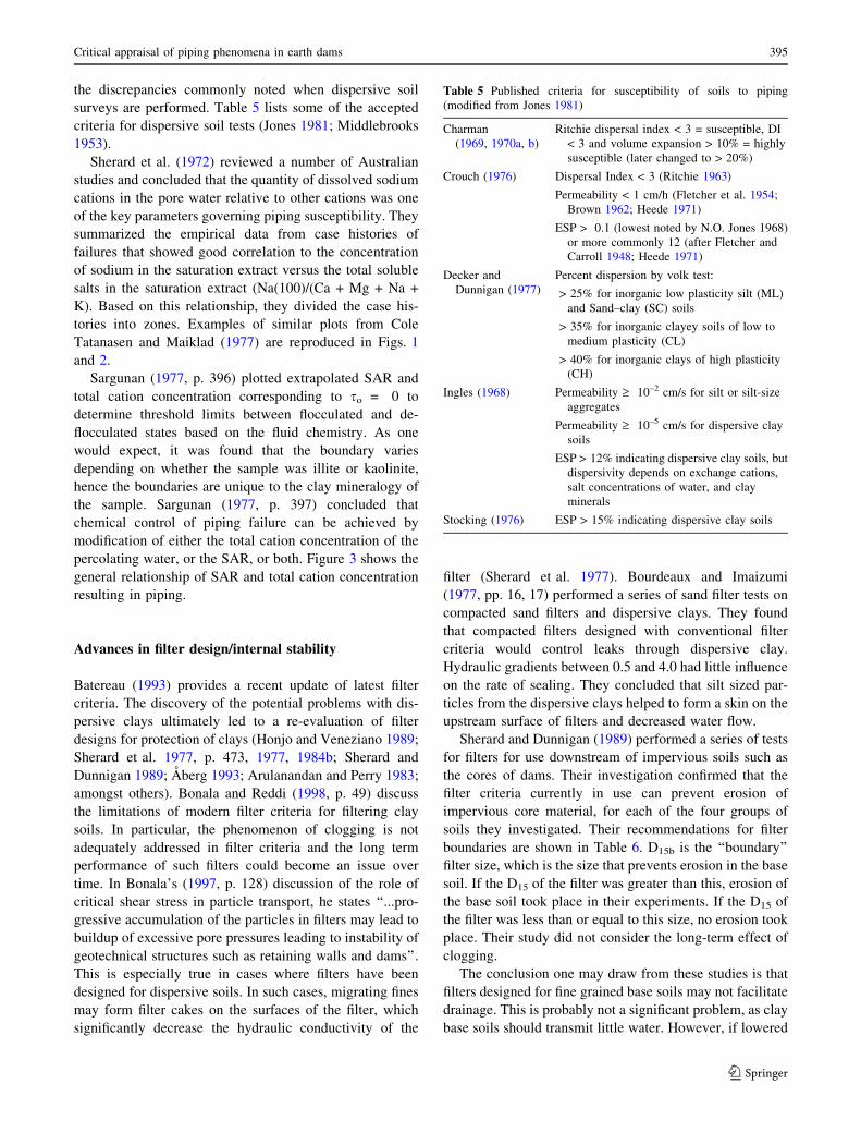
surveys are performed. Table 5 lists some of the accepted
criteria for dispersive soil tests (Jones 1981; Middlebrooks
1953).
Sherard et al. (1972) reviewed a number of Australian
studies and concluded that the quantity of dissolved sodium
cations in the pore water relative to other cations was one
of the key parameters governing piping susceptibility. They
summarized the empirical data from case histories of
failures that showed good correlation to the concentration
of sodium in the saturation extract versus the total soluble
salts in the saturation extract (Na(100)/(Ca + Mg + Na +
K). Based on this relationship, they divided the case his-
tories into zones. Examples of similar plots from Cole
Tatanasen and Maiklad (1977) are reproduced in Figs. 1
and 2.
Sargunan (1977, p. 396) plotted extrapolated SAR and
total cation concentration corresponding to so = 0 to
determine threshold limits between flocculated and de-
flocculated states based on the fluid chemistry. As one
would expect, it was found that the boundary varies
depending on whether the sample was illite or kaolinite,
hence the boundaries are unique to the clay mineralogy of
the sample. Sargunan (1977, p. 397) concluded that
chemical control of piping failure can be achieved by
modification of either the total cation concentration of the
percolating water, or the SAR, or both. Figure 3 shows the
general relationship of SAR and total cation concentration
resulting in piping.
Advances in filter design/internal stability
Batereau (1993) provides a recent update of latest filter
criteria. The discovery of the potential problems with dis-
persive clays ultimately led to a re-evaluation of filter
designs for protection of clays (Honjo and Veneziano 1989;
Sherard et al. 1977, p. 473, 1977, 1984b; Sherard and
Dunnigan 1989; Aberg 1993; Arulanandan and Perry 1983;
amongst others). Bonala and Reddi (1998, p. 49) discuss
the limitations of modern filter criteria for filtering clay
soils. In particular, the phenomenon of clogging is not
adequately addressed in filter criteria and the long term
performance of such filters could become an issue over
time. In Bonala’s (1997, p. 128) discussion of the role of
critical shear stress in particle transport, he states ‘‘...pro-
gressive accumulation of the particles in filters may lead to
buildup of excessive pore pressures leading to instability of
geotechnical structures such as retaining walls and dams’’.
This is especially true in cases where filters have been
designed for dispersive soils. In such cases, migrating fines
may form filter cakes on the surfaces of the filter, which
significantly decrease the hydraulic conductivity of the
filter (Sherard et al. 1977). Bourdeaux and Imaizumi
(1977, pp. 16, 17) performed a series of sand filter tests on
compacted sand filters and dispersive clays. They found
that compacted filters designed with conventional filter
criteria would control leaks through dispersive clay.
Hydraulic gradients between 0.5 and 4.0 had little influence
on the rate of sealing. They concluded that silt sized par-
ticles from the dispersive clays helped to form a skin on the
upstream surface of filters and decreased water flow.
Sherard and Dunnigan (1989) performed a series of tests
for filters for use downstream of impervious soils such as
the cores of dams. Their investigation confirmed that the
filter criteria currently in use can prevent erosion of
impervious core material, for each of the four groups of
soils they investigated. Their recommendations for filter
boundaries are shown in Table 6. D15b is the ‘‘boundary’’
filter size, which is the size that prevents erosion in the base
soil. If the D15 of the filter was greater than this, erosion of
the base soil took place in their experiments. If the D15 of
the filter was less than or equal to this size, no erosion took
place. Their study did not consider the long-term effect of
clogging.
The conclusion one may draw from these studies is that
filters designed for fine grained base soils may not facilitate
drainage. This is probably not a significant problem, as clay
base soils should transmit little water. However, if lowered
Table 5 Published criteria for susceptibility of soils to piping
(modified from Jones 1981)
Charman
(1969, 1970a, b)
Ritchie dispersal index < 3 = susceptible, DI
< 3 and volume expansion > 10% = highly
susceptible (later changed to > 20%)
Crouch (1976) Dispersal Index < 3 (Ritchie 1963)
Permeability < 1 cm/h (Fletcher et al. 1954;
Brown 1962; Heede 1971)
ESP > 0.1 (lowest noted by N.O. Jones 1968)
or more commonly 12 (after Fletcher and
Carroll 1948; Heede 1971)
Decker and
Dunnigan (1977)
Percent dispersion by volk test:
> 25% for inorganic low plasticity silt (ML)
and Sand–clay (SC) soils
> 35% for inorganic clayey soils of low to
medium plasticity (CL)
> 40% for inorganic clays of high plasticity
(CH)
Ingles (1968) Permeability ‡ 10–2 cm/s for silt or silt-size
aggregates
Permeability ‡ 10–5 cm/s for dispersive clay
soils
ESP > 12% indicating dispersive clay soils, but
dispersivity depends on exchange cations,
salt concentrations of water, and clay
minerals
Stocking (1976) ESP > 15% indicating dispersive clay soils
Critical appraisal of piping phenomena in earth dams 395
123

phreatic levels are necessary for stability reasons, standard
filters may not suffice for fine grained base soils. The issue
of clogging in these types of filters has not yet been ade-
quately addressed.
Moffat and Fannin (2006, p. 273) cite Kezdi (1979) and
Kenney and Lau (1985) who quantify the potential for
internal instability based on grain size distribution, and
Skempton and Brogan (1994) who verify the applicability of
the geometric factors elucidated by the earlier workers.
Skempton and Brogan (1994, p. 449) refer to the methods of
Kezdi (1979) for assessing the internal stability of soils. The
general concept is that a soil is divided into its fine and coarse
fractions and treated as a filter and base soil. Terzaghi’s
(1939) filter criteria must be satisfied for the soil to be
internally stable. Permeation tests by Skempton and Brogan
(1994) and Adel et al. (1988) indicated that failure of inter-
nally unstable soils can occur at hydraulic gradients much
lower than predicted by theory. Skempton and Brogan (1994)
theorized that the piping was triggered at lower hydraulic
gradients due to a lower effective stress acting on the finer
fraction. As Moffat and Fannin (2006) elucidated ‘‘...hydro-
mechanical influences governing the onset of instability are
not well understood’’. The stability of non-cohesive materials
and influence of stress is not well developed.
Skempton and Brogan (1994, p. 452) reviewed vertical
flow tests conducted by Kenney and Lau (1985) and note
Fig. 1 Chemical zones and
plots of data from Cole et al.
(1977)
Fig. 2 Examples from other
dams (from Cole et al. 1977)
396 K. S. Richards, K. R. Reddy
123

that there was a question remaining regarding the critical
gradient at which fines began to move (the paper by
Kenney and Lau did not provide enough information to
determine the critical hydraulic gradients). As reported by
Skempton and Brogan (1994), follow-up tests were con-
ducted by Adel et al. (1988) using an apparatus with hor-
izontal flow. The Adel et al. tests reportedly resulted in
critical hydraulic gradients required to initiate piping from
0.16 to 0.7, depending on the degree of internal stability
(Skempton and Brogan 1994, p. 452). Skempton and
Brogan noted that there are no comparable data for the case
of upward flow and subsequently carried out the upward
flow tests. They reported that the vertical tests resulted in
hydraulic gradients that were higher than the horizontal
flow tests of Adel et al. but that the differences were small.
A comparison of the two sets of data are reproduced in
Table 7 (Skempton and Brogan 1994, p. 452).
Some interesting differences in the data not discussed in
Skempton and Brogan (1994) are the apparent discrepan-
cies between the ic for the stable material, and the fact that
the Adel et al. (1988) results for the unstable material show
an ic approximately half that of Skempton and Brogan
(1994). Terzaghi’s (1922) laboratory work on heave was
performed with vertical flow, which yielded the critical
gradient of 1.0. More work is required to assess the
importance of the orientation of the test apparatus in these
types of permeation tests. Skempton and Brogan’s (1994)
and Adel et al. (1988) results apparently indicate that the
critical hydraulic gradient in stable materials can vary from
0.7 to 1.0, depending on the direction of fluid flow. How-
ever, for unstable materials the critical hydraulic gradient
could be roughly 1/3 (vertical flow case) to 1/6 (horizontal
flow case) of the normally anticipated threshold of 1.0,
based on the theory of Terzaghi (1922).
Skempton and Brogan (1994, p. 457) proposed that there
is a reduction factor, depending on the amount of stresses
carried by an unstable fraction of soil, that reduces the
critical hydraulic gradient necessary to commence piping;
ic ¼ ac0=cw ð4Þ
where:
ic = critical hydraulic gradient
a = reduction factor
c = effective unit weight of soil
cw = unit weight of water.
The above equation would be applicable for internally
unstable, gap graded materials prone to suffusion of matrix
soil through a coarser grained, load-bearing skeleton. An
important conclusion from this work is that the distribution
of internal stresses may influence piping potential.
Kezdi (1979), Kenney and Lau (1985) and Aberg (1993)
provide means to test soils for internal stability. A rule
suggested by Skempton and Brogan (1994, p. 452) is that
of Kovacs (1981), which states that materials having a
uniformity coefficient of less than 10 are self filtering and
materials with a uniformity coefficient of more than 20 are
probably unstable. Soils that are gap graded may be prone
to suffusion. Skempton and Brogan (1994, p. 452) termed
this phenomenon- ‘‘segregation piping’’. If enough of the
matrix grains are lost, collapse of the soil skeleton, sink-
holes, or piping may ensue (McCook 2004; Kovacs 1981).
Due to the lack of electro-chemical forces, segregation
piping (suffusion) may be a more common phenomenon in
noncohesive materials.
Recent work
Recent workers have re-emphasized Lane’s (1934) dis-
tinction between piping and internal erosion, to help dif-
ferentiate between the phenomena of flow through granular
media versus flow through cracks or structural contacts
(McCook 2004). Other recent work into piping phenomena
has focused on the development of predictive mathematical
Fig. 3 Soils with low total salt concentrations require less sodium
percentage to become dispersive (Sargunan 1977)
Table 6 Filter boundaries for four soil groups (modified from
Sherard and Dunnigan 1989)
Soil Group Fine content by no.
200 sieve (%)
Filter boundary (D15b)
determined by test
1 85–100 D15b/d85 = 7–12
(average value 9)
2 40–80 D15b = 0.7–1.5 mm
3 0–15 D15b/d85 = 7–10
4 15–40 Intermediate between
groups 2 and 3, depending
on fines content
Critical appraisal of piping phenomena in earth dams 397
123

models for particle transport and filter clogging (Reddi
et al. 2000; Bonala 1997; Reddi and Kakuturu 2006a, b;
Kakuturu 2003; Locke et al. 2001). This work stems from
environmental applications in facilitated transport remedi-
ation techniques. Other continuing work is field research
into dispersive soils and how this impacts natural soils.
This is potentially a growing area as more development
takes place in areas of unstable dispersive soils.
Jones (1981) provided an extensive review of literature
related to piping. Although his primary interest was in soil
piping from the soil geomorphology and hydrological
viewpoints, his review covers many aspects of engineering
related piping. Jones presents an argument that piping in
natural soil has a significant role in geomorphological
development in terms of drainage channel and valley net-
work development, and plays a significant role in hydro-
logical processes. His view is supported by the work of a
number of recent workers (Valentin et al. 2005; Carey and
Woo 2000; Derbyshire 2001; Holden and Burt 2002;
Huddart and Bennett 2000; amongst many others). Jones’
(1981) model for natural soil piping is shown in Fig. 4.
The formation of pipes, tunnels and jugs has been well
documented in areas with dispersive soils. Jones (1981, p.
9) differentiates tunneling phenomena from classical pip-
ing phenomena on the basis that tunneling starts with water
entering surface cracks ‘‘with velocities measured in cm/s
and rarely in m/sec whereas piping occurs deep within a
dam without necessarily following cracks and in flows of
mm/s’’. He states that tunneling is only really effective in
dispersive soils (Sherard, Dunnigan and Decker 1976).
‘‘Tunnelling begins upstream, with saturation settlement in
poorly compacted soil creating a combined crack and dis-
continuity in permeability near the phreatic line as opposed
to piping which begins by hydrodynamic pressure lifting
particles at the downstream exit of seepage’’ (Jones 1981,
p. 10). Hence, on the basis of this definition it appears
tunneling is a vadose zone process.
Other recent work includes the collection of empirical
data concerning dam failures by Foster et al. (2000b) and
assessing the specific failure modes related to piping. This
work, along with the statistical data of Foster et al. (2000a)
is shedding some light on the causes of piping and causing
engineers to reassess the failure mechanisms and genetic
characteristics of piping (McCook 2004). For example,
Foster et al. (2002) found that the hydraulic gradient is not
nearly as important as other factors that lead to piping
failures such as potential seepage paths along conduits and
structures, or some other defect. This is a return to the
earlier observations of Terzaghi (1929) that minor details
in the foundation or a structure can trigger dam failures.
These recent observations also support the earliest views of
piping developed in India by Col. Clibborn and juxtapose
the concept of backwards erosion piping later fostered by
Terzaghi. The backwards erosion model is not as signifi-
cant a cause of dam failures as the minor details that
contribute to piping failures by internal erosion. Review of
the database contained in Table 1 confirms this to be the
case.
Recent work has also been conducted with respect to
estimating the time of development of piping (Fell et al.
2003; Annandale et al. 2004). Numerical and laboratory
investigations are currently being developed to come up
with methods to better predict the timing of pipe devel-
opment.
There is little work that has been completed with respect
to constitutive models of piping. Tomlinson and Vaid
(2000) performed experiments to determine the effects of
confining pressure and seepage forces on piping and found
confining pressures influence the critical hydraulic gradient
to some extent. A mechanistic approach was taken by
Kakuturu (2003), Reddi and Kakuturu (2006a, b) that
predicts progressive erosion versus self healing in dams or
other structures with soil filters, and is based on the rate of
particle release, concentration of suspended particles and
probability of entrapment using a capillary tube model of
porous media. These models are applicable to evaluation of
filter performance and in cases where the performance of
environmental liners is to be evaluated. Yamamuro and
Lade (1997a, b) developed a modified Single Hardening
Model for static liquefaction of silty sands under low
confining stresses that may have some application to piping
research. However, to the writers’ knowledge, no one to
date has attempted to develop a constitutive model of
piping that could be used in a continuum model to predict
the piping behavior of dams.
Recommendations
Piping has been described in the literature as occurring
within the vadose zone. The mechanism described for
piping in the vadose zone precludes piping from forming in
Table 7 Horizontal and vertical flow tests (Skempton and Brogan
1994). H/F is ratio of coarse to fine components
State Horizontal flow
(Adel et al. 1988)
Upward vertical flow
(Skempton and Brogan 1994)
(H/F)min ic (H/F)min ic
Unstable 0.25 0.16 0.14 0.20
0.36 0.17 Not tested Not tested
0.50 0.17 Not tested Not tested
Not tested Not tested 0.98 0.34
Stable 1.3 0.70 1.6 1.0
Not tested Not tested 2.8 1.0
398 K. S. Richards, K. R. Reddy
123

the phreatic zone. Piping has also been described in the
literature as strictly a phreatic condition due to adverse
hydraulic gradients. However, recent literature has indi-
cated that piping is common in areas where the hydraulic
gradients are not that great. Engineering guidance on pip-
ing has taught engineers that hydraulic gradients less than
1.0 are generally safe; yet, there are some instances of
piping where it has occurred at gradients as little as 0.17.
Obviously, the term piping is describing a number of dif-
ferent phenomena, some which are only remotely related.
More work is needed to differentiate these various causes
of piping. Engineers need to have a common language and
understanding of piping when discussing and researching
piping phenomena and understand the various modes of
piping and how to assess piping potential for each mode.
A worldwide clearinghouse of dam failure data, similar
to the University of Stanford’s National Performance of
Dams Program should be developed. It is imperative that
enough details regarding dam failures be recorded in one
database, to allow thorough assessments of dam failure
modes. We recommend that reports of dam failures should
include;
(1) Date of first construction.
(2) Date of failure.
(3) Foundation characteristics.
(4) Dam characteristics (including if dispersive soils are
involved).
(5) Exact location of first piping (or other failure) and its
association with project structures (e.g. piping along
conduit, piping under/along a structure, or piping into
the foundation, etc.).
(6) Timing of the event if it can be reconstructed.
(7) Identify if the incident was caused by structural fail-
ure of a project feature. For example, if piping is
associated with a conduit, if possible, the report
should indicate if it is the result of conduit failure.
Unlike the detailed US National Transportation Safety
Board (NTSB) investigations into aircraft failures, reports
of dam failures are often not as rigorous. However, such
thorough studies would greatly improve the overall safety
of dams by increasing our understanding of the causes of
dam failures.
Piping phenomena have been studied by a large number
of researchers and the list of publications on this topic is
voluminous. However, more research is still needed to fill
in the gaps in our understanding of piping. Many existing
structures were constructed without filters or with inade-
quate filters. Current methods for evaluation of piping
potential are based on theories that were developed almost
100 years ago, which have proven to be inadequate when
one considers the range of mechanisms that fall under the
heading ‘‘piping’’.
Conclusions
Most of the previous work has focused on piping of
cohesive materials, in particular dispersive clays, piping in
natural soils, or filter criteria. Some preliminary work has
been conducted on the statistics of piping failures, which
hopefully will improve as dam failure reporting require-
ments develop further. Excluding the advances in filter
engineering, there have been few significant advances with
respect to piping in non cohesive soils since Lane’s
weighted creep method was published in 1934. Other than
Moffat and Fannin (2006) and Aberg (1993), very little
recent work has been done with respect to piping in
cohesionless soils. Although some headway is being made
with the recent focus on related failures, dams are still
failing by piping and more work remains to be done in this
field. Even in spite of the number of advances in our
understanding of piping phenomena, there are still a large
number of incidents that occur due to concentrated leakage
or formation of sinkholes in embankment dams. This re-
flects a need for increased attention to the prevention of
these potential failure modes.
Fig. 4 Tunneling/piping phenomena common in the vadose zone of
dispersive soils (Jones 1981)
Critical appraisal of piping phenomena in earth dams 399
123

References
Aberg B (1993) Washout of grains from filtered sand and gravel
materials. ASCE J Geotech Eng 119(1):36–53
Adel DH, Bakker KJ, Breteler MK (1988) Internal stability of
minestone. In: Proceedings of international symposium of
modelling soil–water-structure interaction. Balkema, Rotterdam,
pp 225–231
Aitchison GD (1960) In: Proceedings, third Australia-New Zealand
conference on soil mechanics and foundation engineering, p 260
Aitchison GD, Ingles OG, Wood CC (1963) Post-construction
deflocculation as a contributory factor in the failure of earth
dams. In: Fourth Australia-New Zealand conference on soil
mechanics and foundation engineering, p 275
Alizadeh A (1974) Amount and type of clay and pore fluid influences
on the critical shear stress and swelling of cohesive soils. Ph.D.
thesis, University of California, Davis
Annandale GW, Murthy R, Beckwith G (2004) Simulation of dam
breach initiated by cracks and earth fissures in semi-arid and arid
environments. In: Proceedings ASDSO Dam safety. Phoenix,
Arizona
Arulanandan K, Perry EB (1983) Erosion in relation to filter design
criteria in earth dams. ASCE J Geotechn Eng 109(5):682–697
Arulanandan K, Basu R, Scharlin R (1973) Significance of the
magnitude of dielectric dispersion in soil technology. Highway
Research Record, No. 426, pp 23–32
Arulanandan K, Loganathan P, Krone RB (1975) Pore and eroding
fluid influences on surface erosion of soil. ASCE J Geotechn Eng
101(1):51–66
Batereau C (1933) Comparison of existing granular filter criteria. In:
Brauns J, Heibaum M, Schuler U (eds) Filters in geotechnical
and hydraulic engineering. Balkema, Rotterdam, pp 113–119
Bertram GE (1940) An experimental investigation of protective
filters. Soil mechanics series No. 7. Graduate School of
Engineers, Harvard University, Cambridge, Mass
Bertram GE (1967) Experience with seepage control measures in
earth and rockfill dams. Transactions 9th congress on large dams
Istanbul, vol 3, p 91
Bligh WG (1910) Dams, barrages and weirs on porous foundations.
Eng News 64(26):708–710
Bligh WG (1911b) Weirs on porous foundations and with pervious
floors. Eng News 65(15):444–445
Bligh WG (1911a) Reply to sheet piles as a means of decreasing
permeability of porous foundations. In: Fielding JS (ed)
Engineering news, vol 65, No. 4, p 109
Bligh WG (1913) Lessons from the failure of a weir and sluices on
porous foundations. Eng News 69(6):266–270
Bonala MVS (1997) Role of critical shear stress in erosion, drainage,
and mechanical behavior of soils. Ph.D. Dissertation, Kansas
State University, Manhattan, Kansas, USA
Bonala MVS, Reddi LN (1998) Physicochemical and biological
mechanisms of soil clogging: an overview. ASCE Geotech Spec
Publ, No. 78, pp 43–68
Bourdeaux G, Imaizumi H (1977) Dispersive clay at Sobradinho
Dam. In: Sherard JL, Decker RS (eds) Dispersive clays, related
piping, and erosion in geotechnical projects. ASTM Special
Technical Publication 623, p. 13
Brown GW (1962) Piping erosion in Colorado. J Soil and Water
Conserv, pp 220–222
Burenkova VV (1993) Assessment of suffosion in non-cohesive and
graded soils. In: Brauns J, Heibaum M, Schuler U (eds) Filters in
geotechnical and hydraulic engineering. Balkema, Rotterdam,
pp. 357–360
Carey SK, Woo MK (2000) The role of soil pipes as a slope runoff
mechanism, Subarctic Yukon, Canada. J Hydrol 233(1–4):206–222
Casagrande A (1937) Seepage through dams. Contributions to soil
mechanics 1925–1940. Boston Society of Civil Engineers, 1940
(reprinted from J New Engl Water Works Assoc, vol 51, pp 131–
172, 1937) p 295
Cedergren HR (1977) Seepage, drainage, and flow nets, 2nd edn.
Wiley, New York, pp 1–534
Charman PEV (1969) The influence of sodium salts on soils with
reference to tunnel erosion in coastal areas, Part I: Kemsey area.
J Soil Conserv Serv, NSW 25(4):327–342
Charman PEV (1970a) The influence of sodium salts on soils with
reference to tunnel erosion in coastal areas, Part II: Grafton area.
J Soil Conserv Serv, NSW 26(1):71–86
Charman PEV (1970b) The influence of sodium salts on soils with
reference to tunnel erosion in coastal areas, Part III: Taree area.
J Soil Conserv Serv, NSW 26(4):256–275
Clibborn J (1902) Experiments on the passage of water through sand.
Govt. of India, Central Printing Office
Cole BA, Tatanasen C, Maiklad P, Liggins TB, Chirapuntu S (1977)
Dispersive clay in irrigation dams in Thailand. In: Sherard JL,
Decker RS (eds) Dispersive clays, related piping, and erosion in
geotechnical projects. ASTM Special Technical Publication, vol
623, p 25
Coumoulos DG (1977) Experience with studies of clay erodibility in
Greece. In: Sherard JL, Decker RS (eds) Dispersive clays,
related piping, and erosion in geotechnical projects. ASTM
Special Technical Publication, vol 623, p 42
Crouch RJ (1976) Field tunnel erosion – a review. J Soil Conserv
Serv, NSW 32(2):98–111
Crouch RJ (1977) Tunnel-gully erosion and urban development: a
case study. In: Sherard JL, Decker RS (eds) Dispersive clays,
related piping, and erosion in geotechnical projects. ASTM
Special Technical Publication, vol 623, pp 57–60
Darcy H (1865) Les fontaines publiques de la Ville de Dijon.
Dalmont, Paris
Decker RS, Dunnigan LP (1977) Development and use of the soil
conservation service dispersion test. In: Sherard JL, Decker RS
(eds) Dispersive clays, related piping, and erosion in geotechni-
cal projects. ASTM Special Technical Publication, vol 623, pp
94–109
Derbyshire E (2001) Geological hazards in loess terrain, with
particular reference to the loess regions of China. Earth Sci
Rev 54(1–3):231–260
Emerson WW (1967) A classification of soil aggregates based on
their coherence in water. Aust J Soil Res 5:47–57
Fell R, Wan CF, Cyganiewics J, Foster M (2003) Time for
development of internal erosion and piping in embankment
dams. J Geotech Geoenviron Eng 129(4):307–314
FERC (2005) Engineering guidelines for the evaluation of hydro-
power projects. http://www.ferc.gov/industries/hydropower/
safety/guidelines/eng-guide.asp, pp 1.1–14.I.53
Fletcher JE, Carroll PH (1948) Some properties of soils that are
subject to piping in southern Arizona. Soil Sci Soc Am Proc
13:545–547
Fletcher JE, Harris E, Peterson HB, Chandler VN (1954) Piping.
Trans Am Geophys Union 35(2):258–262
Forcheimer P (1886) Uber die Ergiebigkeit von Brunnenanlagen und
Sickerschlitzen. Zeitschrift, Architekten und Ingenier-Verein
Hannover 32(7):539–564
Forsythe P (1977) Experiences in identification and treatment of
dispersive clays in Mississippi dams. In: Sherard JL, Decker RS
(eds) Dispersive clays, related piping, and erosion in geotechni-
cal projects. ASTM Special Technical Publication, vol 623, pp
135–155
Foster M, Fell R, Spannagle M (2000a) The statistics of embankment
dam failures and accidents. Can Geotech J 37(5):1000–1024
400 K. S. Richards, K. R. Reddy
123

Foster M, Fell R, Spannagle M (2000b) A method for assessing the
relative likelihood of failure of embankment dams by piping.
Can Geotech J 37(5):1025–1061
Foster M, Fell R, Spannagle M (2002) A method for assessing the
relative likelihood of failure of embankment dams by piping:
reply. Can Geotech J 39:497–500
Franco GE, Bagtzoglou AC (2002) An elastic contact mechanics
fracture flow model. In: 15th ASCE engineering mechanics
conference. 2–5 June 2002, Columbia University, New York,
NY, (http://www.engr.uconn.edu/~ucremed/pdf/asce_425.pdf),
pp 1–7
Galarowski T (1976) New observations of the present-day suffosion
(piping) processes in the Bereznica catchment basin in the
Bieszczady Mountains (The East Carpathians). Studia Geomor-
phologica Carpatho-Balcanica (Krakow) 10:115–122
Glossop R (1945) Soil mechanics in foundations and excavations. In:
The principles and application of soil mechanics. London lecture
series, Institution of Civil Engineers, pp 63–90
Griffith WM (1913–1914) The stability of weir foundations on sand
and soil subject to hydrostatic pressure. In: Minutes of
Proceedings, Institute of Civil Engineers, vol. 197, Pt. III, p 221
Harr ME (1962) Groundwater and seepage. McGraw-Hill, London, p
315
Heede BH (1971) Characteristics and processes of soil piping in
gullies. US Department of Agriculture, Forest service research
paper, RM-68, pp 1–15
Heinzen R (1976) Erodibility criteria for soils. M.S. Thesis,
University of California, Davis
Heinzen RT, Arulanandan K (1977) Factors influencing dispersive
clays and methods of identification. In: Sherard JL, Decker RS
(eds) Dispersive clays, related piping, and erosion in geotechni-
cal projects. ASTM Special Technical Publication, vol 623, pp
202–217
Holden J, Burt TP (2002) Piping and pipeflow in a deep peat
catchment. CATENA 48:(3)163–199
Honjo Y, Veneziano D (1989) Improved filter criterion for
cohesionless soils. J Geotech Eng 115(1):75–94
Huddart D, Bennett MR (2000) Subsidence structures associated with
subaerial desiccation-crack piping and their role in drainage
evolution on a drained proglacial lake bed: Hagavatn, Iceland. J
Sediment Res 70(5 Part A):985–993
Ingles OG (1968) Soil chemistry relevant to the engineering
behaviour of soils. In: Lee (ed) Soil Mechanics – selected
topics, Butterworth, London
Jansen RB (1983) Dams and public safety. Water Resources
Technical Publication, US Department of the Interior, Bureau
of Reclamation, pp 14–16
Jones JAA (1981) The nature of soil piping: a review of research.
BGRG research monograph 3. Geo Books, Norwich
Kakuturu SP (2003) Modeling and experimental investigations of
self-healing or progressive erosion of earth dams. Ph.D.
dissertation, Kansas State University, pp 1–177
Kandiah A, Arulanandan K (1974) Erosion of cohesive soils.
Transportation Research Board, No. 497, pp 60–68
Kenney TC, Lau D (1985) Internal stability of granular filters. Can
Geotech J Ottawa Can 22:215–225
Kezdi A (1979) Soil physics selected topics—developments in
geotechnical engineering 25. Elsevier, Amsterdam, pp 1–160
Kovacs G (1981) Developments in water science—seepage hydrau-
lics, Chap 3.2. Elsevier, Amsterdam, pp 349–379
Kral V (1975) Sufoze a jeji podil na soucasnych geomorphologickych
procesech v Cechach. Acta Univ Carol Geogr 1–2:22–30
Ladd CC (1960) Mechanisms of swelling by compacted clay. Bulletin
275, Highway Research Board
Lambe TW, Whitman RV (1969) Soil Mech. Wiley, New York p 553
Lane EW (1934) Security from under-seepage masonry dams on earth
foundations. Trans ASCE 60(4):929–966
Legget RF (1939) Soil and soil mechanics. In: Geology and
engineering, McGraw-Hill, New York, pp 538–583
Locke M, Indraratna B, Adikari G (2001) Time-dependent particle
transport through granular filters. J Geotech Geoenviron Eng
127(6):521–529
Louis C (1969) A study of groundwater flow in jointed rock and its
influence on the stability of rock masses. Report No. 10, Imperial
College, London, England
Lutz JF (1934) The physico-chemical properties of soils affecting soil
erosion. Research Bulletin No. 212. Agricultural Experiment
Station, University of Missouri, Columbia, Missouri
Marshall AF, Workman JP (1977) Identification of dispersive clays in
the Texas Gulf Coast area. In: Sherard JL, Decker RS (eds)
Dispersive clays, related piping, and erosion in geotechnical
projects. ASTM Special Technical Publication, vol 623, pp 274–
286
McCook DK (2004) A comprehensive discussion of piping and
internal erosion failure mechanisms. In: Proceedings, annual
dam safety conference, ASDSO. Phoenix, Arizona
Middlebrooks TA (1953) Earth-dam practice in the United States.
Transactions ASCE Centennial Volume, p 697
Moffat RA, Fannin RJ (2006) A large permeameter for study of internal
stability in cohesionless soils. Geotech Test J 29(4):273–279
Newton CT, Hurley HW (1940) An investigation to determine the
practical application of natural bank gravel as a protective filter
for an earth embankment. Thesis (M.S.), Massachusetts Institute
of Technology, Dept of Civil and Sanitary Engineering, p 120
Pavlov AP (1898) Concerning the contour of plains and its change
under the influence of the action of subterranean and surface
waters. Zemlevedeniye 5:91–147
Reddi LN, Kakuturu SP (2006a) Evaluation of the parameters
influencing self-healing in earth dams. J Geotech Geoenviron
Eng 879–889
Reddi LN, Kakuturu SP (2006b) Mechanistic model for self-healing
of core cracks in earth dams. J Geotech Geoenviron Eng 890–
901
Reddi LN, Ming X, Hajra MG, Lee IM (2000) Permeability reduction
of soil filters due to physical clogging. ASCE J Geotech
Geoenviron Eng 126(3):236–246
Riley J, Arulanandan K (1972) A method for measuring the
erodibility of a soil. Technical Note 722, Department of Civil
Engineering, University of California, Davis
Ritchie JA (1963) Earthwork tunneling and the application of soil-
testing procedure. J Soil Conserv Serv NSW 19(3):111–129
Rosewell CJ (1977) Identification of susceptible soils and control of
tunneling failure in small earth dams. In: Sherard JL, Decker RS
(eds) Dispersive clays, related piping, and erosion in geotechni-
cal projects. ASTM Special Technical Publication, vol 623, pp
362–369
Ryker NL (1977) Encountering dispersive clays on SCS projects in
Oklahoma. In: Sherard JL, Decker RS (eds) Dispersive clays,
related piping, and erosion in geotechnical projects. ASTM
Special Technical Publication, vol 623, pp 370–389
Sargunan A (1977) Concept of critical shear stressing relation to
characterization of dispersive clays. In: Sherard JL, Decker RS
(eds) Dispersive clays, related piping, and erosion in geotechni-
cal projects. ASTM Special Technical Publication, vol 623, 390–
397
Sherard JL (1971) Study of piping failures and erosion damage from
rain in clay dams in Oklahoma and Mississippi. Report prepared
for the Soil Conservation Service, Washington, D.C
Sherard JL (1976) Pinhole test for identifying dispersive soils. J
Geotech Div ASCE
Critical appraisal of piping phenomena in earth dams 401
123

Sherard JL, Dunnigan LP (1989) Critical filters for impervious soils. J
Geotech Eng Proc ASCE 115(7): 927–947
Sherard JL, Woodward RJ, Gizienski SF, Clevenger WA (1963) Earth
and earth-rock dams, engineering problems of design and
construction. Wiley, New York, pp 114–130
Sherard JL, Decker RS, Ryker NL (1972) Piping in earth dams of
dispersive clay. In: Proceedings, specialty conference on
performance of earth and earth-supported structures. Purdue
University, Indiana, June 1972, American Society of Civil
Engineers, vol 1, Part 1, pp 589–626
Sherard JL, Dunnigan, LP, Decker, RS (1977) Some engineering
problems with dispersive clays. In: Sherard JL, and Decker RS
(eds) Dispersive clays, related piping, and erosion in geotechnical
projects. ASTM Special Technical Publication, vol 623, pp 1–11
Sherard JL, Dunnigan LP, Talbot JR (1984a) Basic properties of sand
and gravel filters. ASCE J Geotech Eng 110:684–700
Sherard JL, Dunnigan LP, Talbot JP (1984b) Filters for silts and
clays. J Geotech Eng ASCE 110(6):701–718
Sherman WC (1953) Filter experiments and design criteria. NTIS
AD-771-076, US Army Waterways Experiment Station, Vicks-
burg, VA
Skempton AW, Brogan JM (1994) Experiments on piping in sandy
gravels. Geotechnique 44(3):449–460
Stapledon DH, Casinader RJ (1977) Dispersive soils at Sugar Loaf
Dam site, near Melbourne, Australia. In: Sherard JL, Decker RS
(eds) Dispersive clays, related piping, and erosion in geotechni-
cal projects. ASTM Special Technical Publication, vol 623, pp
432–466
Stocking MA (1976) Tunnel erosion. Rhodesia Agri J 73(2):35–39
Terzaghi K (1922) Der Grundbruch an Stauwerken und seine
Verhutung (The failure of dams by piping and its prevention).
Die Wasserkraft, vol 17, pp 445–449. Reprinted in (1960) From
theory to practice in soil mechanics. Wiley, New York
Terzaghi K (1925) Erdbaumechanik. Franz Deuticke, Vienna
Terzaghi K (1929) Effect of minor geologic details on the safety of
dams. Am Inst Min Met Eng Tech Publ 215:31–44
Terzaghi K (1939) Soil mechanics: a new chapter in engineering
science. J Instn Civ Eng 12:106–141
Terzaghi K (1943) Theoretical soil mechanics. Wiley, New York, pp
1–510
Terzaghi K, Peck RB (1948) Soil mechanics in engineering practice.
Wiley, New York
Terzaghi K, Peck RB, Mesri G (1996) Soil mechanics in engineering
practice, 3rd edn. Wiley, New York
von Thun J (1985) Application of statistical data from dam failures
and accidents to risk-based decision analysis on existing dams.
US Bureau of Reclamation October
Tomlinson S, Vaid Y (2000) Seepage forces and confining pressure
effects on piping erosion. Can Geotech J 37(1): 1–13
US Bureau of Reclamation (1947) Laboratory tests on protective
filters for hydraulic and static structures. Earth Laboratory
Report EM-132. National Technical Information Service,
Springfield, VA
US Bureau of Reclamation (1987) Design of small dams, 3rd edn. US
Department of Commerce, National Technical Information
Service, Springfield, VA, pp 1–860
USACE (1993) Engineering and design-Seepage analysis and control
for dams with CH 1. EM 1110-2-1901, http://www.usace.army.-
mil/publications/eng-manuals/em1110-2-1901/toc.htm, Depart-
ment of the Army, US Army Corps of Engineers, Washington,
D.C., pp 1.1 – D.10
Valentin C, Poesen J, Yong Li (2005) Gully erosion: impacts, factors
and control. CATENA http://www.sciencedirect.com
Villegas F (1977) Experiences with tests of dispersibility of fine-
grained soils for dams in Colombia. In: Sherard JL, Decker RS
(eds) Dispersive clays, related piping, and erosion in geotechni-
cal projects. ASTM Special Technical Publication, vol 623, pp
408–418
Waterways Experiment Station, Corps of Engineers, US Army (1941)
Investigation of filter requirements for underdrains. Technical
Memorandum No. 183-1, Vicksburg, Mississippi, p 35
Waterways Experiment Station, Corps of Engineers, US Army (1942)
Field and laboratory investigation of design criteria for drainage
wells. Technical Memorandum No. 195-1, Vicksburg, Mis-
sissippi, p 78
Waterways Experiment Station, Corps of Engineers, US Army (1948)
Laboratory investigation of filters for Enid and Grenada dams.
Technical Memorandum No. 3-245, Vicksburg, Mississippi, p 50
Woerman A, Olafsdottir R (1992) Erosion in a granular medium
interface. J Hydrol Res 30:639–655
Yamamuro JA, Lade PV (1997b) Static liquefaction of very loose
sands. Can Geotech J 34:905–917
Yamanmuro JA, Lade PV (1997a) Behaviour and modelling of static
liquefaction of silty sands. Numer Models Geomech 7:27
402 K. S. Richards, K. R. Reddy
123