critical speed.pdf
TRANSCRIPT
8/10/2019 critical speed.pdf
http://slidepdf.com/reader/full/critical-speedpdf 1/10

8/10/2019 critical speed.pdf
http://slidepdf.com/reader/full/critical-speedpdf 2/10
Mili J. Hota & D.P. Vakharia
242
number of excellent texts, but it can be difficult to quickly pull out the practical insight
needed. At the other end of the spectrum, there is also a large number of
troubleshooting resources that focus on identification of problems and characteristics,
but only offer limited insight. Discussion of recent combined experimental and
analytical effort raised the possibility of an article that would attempt to provide a
deeper insight into some of the basic characteristics of rotating machinery vibration
from a less mathematical perspective.
Thus in this article several issues that are basic to an understanding of rotating
machinery vibration are been discussed:
• What are “critical speeds”?
• How do critical speeds relate to resonances and natural frequencies?
• How do natural frequencies change as the shaft rotational speed changes?
•
How are shaft rotational natural frequencies different from more familiarnatural frequencies and modes in structures?
• What effects do bearing characteristics have?
2. Vibration Intuition2.1 A Brief Review of Structural Vibration
As engineers, we learn that vibration characteristics are determined by a structure’s
mass and stiffness values, with damping (ability to dissipate vibrational energy)
playing an integral role by controlling amplitudes. This education generally starts with
the simplest possible system – a rigid mass attached to a spring as shown in Fig. 1[1].
With this simple system, we quantify our intuition about vibrational frequency (heavierobjects result in lower frequency, stiffer springs yield higher frequency). After some
work, we reach the conclusion that the free vibration frequency is controlled by the
square root of the ratio of stiffness to mass as shown in Fig. 1. We could then add a
viscous damper parallel with the spring, and provide a sinusoidal force as shown in
Fig. 2[3]. By carefully applying a constant amplitude sinusoidal force that slowly
increases in frequency and recording the amplitude of the motion, we could then
generate the classic normalized frequency responses of a spring-mass-damper system.
By repeating the test with a variety of dampers, the classic frequency response shown
in Fig. 3 can be developed. Assuming we knew the mass, stiffness and damping of our
system, this response is also predicted quite well by the standard frequency domain
solution to the differential equation of motion for this system shown in Equation 1[2].
222
0
1 ⎟ ⎠
⎞⎜⎝
⎛ +⎟⎟
⎠
⎞⎜⎜⎝
⎛ −
=
k
c
k
m
k
F
Amplitude
ω ω
(1)
There are several noteworthy points about these frequency responses. The first is
that at low excitation frequencies, the response amplitude is roughly constant and
greater than zero. The amplitude is governed by the ratio of the applied force to the

8/10/2019 critical speed.pdf
http://slidepdf.com/reader/full/critical-speedpdf 3/10
A R
spri
dec
app
res
fre
exc
pos
con
The
am
con
sec
doso
fre
res
res
mul
uni
am
Fi
eview of R
ng stiffnes
eases in
roximately
onse freq
uency as d
tation freq
sible when
trolled by t
high dam
litude cont
trasted wit
ion. Movin
ot change.e changes
uency is a
onses. Res
onse peak
tiple natur
ue “mode
litudes and
ig. 1: Sim
with a
. 2: Free r
tating Ma
[6]. The
the low
the dampe
ency, whi
amping in
ency matc
the excitat
he magnitu
ing case h
inues to de
the respo
g from the
Natural fredue to d
resonance.
onse ampl
can be co
l frequen
-shape” w
differing p
le spring-
d without
sponse of
ass- syste
hinery Crit
econd is t
and medi
natural fr
h moves
reases). T
es the da
ion freque
de of the d
s no real p
rease for a
nse of a r
simple sin
quencies ar mping. E
Excitation
itudes are c
pletely eli
ies and th
th differe
hases relati
ass- syste
amper.
imple spri
ical Speed
at the resp
m dampi
quency, (
down in
e system i
ped natura
cy is clos
amping (m
eak, and is
l higher fre
tating syst
le mass sy
e still primcitation fr
near a re
ontrolled b
inated. Th
at each na
t parts of
ve to one a
g-
Fig.
damp
Fig. 4
and Mode
nse increa
g cases.
ore techni
requency
s said to b
frequency
to this fr
ore dampi
said to be
quencies. T
em to unb
stem to mu
rily related equency e
onance ca
damping.
e biggest c
tural frequ
the struct
other.
: Frequenc
r system to
: Basic ma
of Vibrati
ses to a pe
This pea
ally corre
rom the
“in reson
. Very larg
quency. T
g reduces
‘overdamp
hese chara
lance exci
ltimass sys
to mass anual to a
result in
With enou
ange is th
ncy has a
ure vibrati
response
constant a
hine mode
ns
k, then ra
frequenc
t, it is the
amped na
nce” whe
amplitude
e amplitu
he amplitu
d.’ Finally
teristics wi
ation in a
ems, the b
d stiffness,amped na
arge ampli
h damping
t there are
correspon
ng at diff
f spring m
plitude fo
cross secti
243
idly
is
eak
tural
the
s are
e is
es).
, the
ll be
later
sics
withtural
tude
, the
now
ding
rent
ass
rce.
on.

8/10/2019 critical speed.pdf
http://slidepdf.com/reader/full/critical-speedpdf 4/10
244
2.2
The
lu
‘Je
to i
4[5
mo
No
Sup
da
dire
areThr
fre
pin
sho
wit
dis
opp
stif
inte
Th
incinte
the
Thi
off-
cha
If
wo
pre
am
F
A Simple
rotating
ped mass
fcott’ or ‘L
troduce ro
, consists
nted beari
rotating
pose that o
ping, and t
ctions (all
three versiough eith
uencies/m
ed beam).
s the first
the bea
lacement.
osite side
ness to sha
rmediate b
s, these ar
eases (or aresting feat
disk transl
s general c
center, we
acteristic
e repeate
ld get ver
iously. Th
litude, and
g. 5: Mode
stiffness,
otating
achinery
n a massl
aval’ mode
tor dynami
f a rigid c
gs.
ynamics
ur simple
hat the bea
typical cha
ns of thisr analysis
des. At ea
This behav
three mod
, the thic
s it vibra
of the disp
t stiffness
earings, th
generally
shaft stiff ure of the
tes withou
aracteristi
would fin
ill give ris
the const
similar b
re would b
adecay in
shapes ver
shaft not r
achine
equivalent
ess, elastic
l, is a singl
characteri
ntral disk,
achine is
ings have
racteristics
achine, oor a m
ch frequen
or is what
shapes an
line sho
es, it mov
laced cent
as a signif
shaft doe
referred to
ness decreaode shape
t rocking.
repeats a
that the
e to some i
ant amplit
havior as
e a spring-
mplitude
sus bearing
otating.
to the sin
shaft. Thi
degree of
stics. This
a shaft (wi
ot spinnin
qual radial
of ball bea
e each witdal test,
cy, the m
e would e
frequenci
s the sha
s from thi
rline, and
cant impac
not bend
as “rigid r
ses), the a is how th
n the seco
the frequ
otion is a
nteresting
de excitati
ith the sp
ontrolled
ith further
Fig. 6:
s
Mi
le spring-
model, h
freedom s
model, sho
h stiffness
, that the b
stiffness in
rings). Let
soft, inter we woul
tion is pla
xpect from
es for the t
t centerlin
position t
back. Not
t on the mo
very muc
otor” mode
ount of sh central dis
d mode, it
ncy increa
mix of tra
ehavior o
on frequen
ring-mass-
eflection at
ncreases i
Shaft rotat
ape and fr
li J. Hota
ass damp
storically
stem that i
wn in cros
and mass)
earings ha
the vertica
us also su
mediate an find a
nar (just l
a static str
ree bearin
e shape at
the same
that the
de-shapes.
in the lo
s. As the
aft bendink moves. I
rocks wit
ses. If we
slation an
ce the shaf
cy sweep
amper sys
low frequ
frequency.
ng at 10 rp
quencies i
D.P. Vakh
er system
eferred to
generally
-section in
and two ri
e essentiall
l and horiz
pose that
d stiff bear set of na
ke the pin
cture. Fig.
stiffnesse
the maxi
location o
atio of be
For the sof
er two m
earing stif
increases.the first
out transla
moved the
d rocking.
t starts rota
experiment
em plot s
ncies, a pe
m,1st mod
rpm.
aria
is a
as a
used
Fig.
idly
y no
ntal
here
ngs.tural
ned-
5[3]
. As
um
the
ring
and
des.
ness
Oneode,
tion.
disk
This
ting.
we
own
k in

8/10/2019 critical speed.pdf
http://slidepdf.com/reader/full/critical-speedpdf 5/10
A R
3. Sin
to t
ver
hav
the
nat
mo
fre
cas
sha
Thecirc
The
refe
bou
‘tra
the
the
ove
whi
sa
the
whi
dire
the
We
mo
eview of R
Fig.
Rotatinge rotating
e first mo
ions with
e equal sti
shaft spinn
ral freque
e of the t
uencies, th
, the beari
e. Again,
se modesular motio
To visualiz
rope trac
rred to as
ncing up
slatory’ m
same direc
labels “for
r the cour
rl. Note t
e directionThus, for s
outside of
rl, on the
ction as the
To see ho
analysis/m
could then
e. Fig. 8
tating Ma
: Whirl se
Dynamimachinery
e of our r
ncreasing
fness in all
ng at 10 r
cy. Fig. 6
ree machi
ugh, are q
ng stiffnes
the case w
look veryrather tha
e how the
s the outl
a ‘cylindri
nd down.
ode. The w
ion as the
ard whirl
e of time
at for for
as the whir nchronous
the rotor r
ther hand,
whirl to th
a wider ra
dal test wi
follow the
lots the f
hinery Crit
se.
s – Cylinhas to rotat
tor once it
earing sti
radial dire
m, and loo
elow sho
nes. Note
ite close t
to shaft s
ith almost
much like planar mo
otor is mo
ne of a b
al’ mode.
Thus, this
hirling mot
haft’s rotat
and “back
for both s
ard whirl,
l.forward w
mains to t
a point at
e inside of
nge of sha
th a range
forward a
rward (red
ical Speed
Fig. 8
drical Me to do use
is spinnin
fness, and
ctions. Let
k at the fre
s the frequ
hat the sh
the nonrot
tiffness rat
o shaft be
the non r ion.
ing, first i
lging cyli
Viewed fr
mode is
on of the r
ion or in th
ward whirl.
nchronous
a point on
irl (unbala
he outside
the surfac
he whirl or
t speeds c
of shaft sp
d backwar
line) and
and Mode
: Effect of
desful work, l
. Again,
we will as
’s repeat o
quency and
encies and
pe of the
ating first
o has a st
nding is re
tation mod
agine swi
nder. Thus
m the fro
lso someti
tor (the ‘j
e opposite
.” Fig. 7[8]
forward a
the surface
nce excitati
of the whi
e of the ro
bit during t
anges the s
eds from n
frequenci
backward (
of Vibrati
perating s
odes.
t’s consid
e will hav
ume our s
r analysis/
mode sha
mode shap
motion ha
ode. As in
ong impac
ferred to a
es, but th
nging a ju
, this mod
t, the rop
mes called
mprope’ m
irection. T
shows rot
d synchro
of the rot
on, for exa
l orbit[9].
tor moves
e whirl.
ituation, w
on spinnin
es associat
black dash
ns
eed on 1st
r what hap
three diff
upport bea
modal test
e of the lo
es or the lo
s changed.
the nonrot
t on the m
s a rigid
y now in
p rope aro
e is somet
appears t
a ‘bounc
otion) can
his gives ri
r cross sec
nous back
r moves i
ple), a poi
With back
in the opp
could per
to high s
d with the
ed line) na
245
pens
rent
ings
with
west
west
The
ting
ode-
ode.
olve
und.
mes
o be
’ or
e in
se to
ions
ard
the
nt at
ard
osite
orm
eed.
first
tural
8/10/2019 critical speed.pdf
http://slidepdf.com/reader/full/critical-speedpdf 6/10
Mili J. Hota & D.P. Vakharia
246
frequencies over a wide shaft speed range. This plot is often referred to as a “Campbell
Diagram.” From this figure, we can see that the frequencies of this cylindrical mode do
not change very much over the speed range. The backward whirl mode drops slightly,
and the forward whirl mode increases slightly (most noticeably in the high stiffness
case). The reason for this change will be explored in the next section.
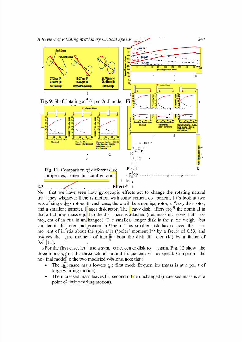
4. Rotating Dynamics – Conical Mode Now that we have explored the cylindrical mode, let’s look at the second set of modes.
Fig. 9 shows the next frequencies and mode-shapes for the three machines. The
frequencies are close to the nonrotating modes where the disk was rocking without
translating. The modes look a lot like the nonrotating modes, but again involve circular
motion rather than planar motion. To visualize how the rotor is moving, imagine
holding a rod stationary in the center, and moving it so that the ends trace out twocircles. The rod traces the outline of two bulging cones pointed at the center of the rod.
Thus, this mode is sometimes referred to as a ‘conical’ mode. Viewed from the side,
the rod appears to be rocking up and down around the center, with the left side being
out-of-phase from that on the right. Thus, this mode is also sometimes called a ‘rock’
mode or a ‘pitch’ mode.
As with the first mode and the nonrotating modes, the low bearing stiffness mode
is generally referred to as a rigid mode, and a high bearing stiffness pulls in the rotor
ends. As with the cylindrical mode, the whirl can be in the same direction as the rotor’s
spin (“forward whirl”), or the opposite direction (“backward whirl”).
To see the effects of changing shaft speeds, we could again perform the
analysis/modal test from non spinning to a high spin speed and follow the two
frequencies associated with the conical mode. Fig. 10 plots the forward (red line) and
backward (black dashed line) natural frequencies over a wide speed range. From this
figure, we can see that the frequencies of the conical modes do change over the speed
range. The backward mode drops in frequency, while the forward mode increases.
The explanation for this surprising behavior is a gyroscopic effect that occurs
whenever the mode shape has an angular (conical/rocking) component. First consider
forward whirl. As shaft speed increases, the gyroscopic effects essentially act like an
increasingly stiff spring on the central disk for the rocking motion. Increasing stiffness
acts to increase the natural frequency. For backward whirl, the effect is reversed.
Increasing rotor spin speed acts to reduce the effective stiffness, thus reducing thenatural frequency (as a side note, the gyroscopic terms are generally written as a skew-
symmetric matrix added to the damping matrix – the net result, though, is a stiffening/
softening effect). In the case of the cylindrical modes, very little effect of the
gyroscopic terms was noted, since the center disk was whirling without any conical
motion. Without the conical motion, the gyroscopic effects do not appear. Thus, for the
soft bearing case, which has a very cylindrical motion, no effect was observed, while
for the stiff bearing case, which has a bulging cylinder (and thus conical type motion
near the bearings), a slight effect was noted.
8/10/2019 critical speed.pdf
http://slidepdf.com/reader/full/critical-speedpdf 7/10
A R
Fi
2.3
No
fre
sets
and
that
mo
sm
mo
red
0.6
thre
no
eview of R
g. 9: Shaft
shapes
Fig. 11: Co
properties,
Exploring
that we
uency whe
of single d
a smaller
a fictitiou
ent of in
ller in dia
ent of in
ces the
[11].
For the firs
e models,
inal model
• The in
large w
• The inc
point o
tating Ma
otating at
nd freque
mparison o
center dis
Gyroscopi
have seen
never there
isk rotors. I
iameter, l
mass equa
rtia is unc
eter and
rtia about
ass mome
t case, let’
nd the thr
to the two
reased ma
hirling mot
reased mas
little whirl
hinery Crit
0 rpm,2nd
cies in rpm
f different
configurat
c and Mas
how gyros
is motion
n each case
nger disk r
l to the dis
hanged). T
greater in
the spin a
t of inerti
use a sym
ee sets of
modified v
s lowers t
ion).
s leaves th
ing motion
ical Speed
mode Fi
isk
ion
Fi
p
Effects
copic effec
with some
, there will
otor. The
mass is a
e smaller,
ength. Thi
is (‘polar’
a about th
etric, cen
atural freq
rsions, not
e first mo
second m
).
and Mode
. 10: Effec
2nd na
. 11: Com
roperties, o
ts act to c
conical co
be a nomin
eavy disk
ttached (i.e
longer dis
s smaller
moment Ip
e disk dia
er disk rot
uencies ve
e that:
de frequen
de unchan
of Vibrati
of oppera
tural frequ
arison of
verhung co
hange the
ponent, l
al rotor, a
iffers fro
., mass inc
k is the sa
isk has re
) by a fact
eter (Id)
r again. Fi
sus speed.
ies (mass
ged (increa
ns
ing speed
ncies
ifferent dis
nfiguration
rotating na
t’s look at
eavy disk r
the nomin
eases, but
me weight
uced the
or of 0.53,
by a facto
g. 12 show
Comparin
is at a poi
sed mass is
247
n
k
tural
two
otor,
al in
ass
but
ass
and
r of
the
the
t of
at a

8/10/2019 critical speed.pdf
http://slidepdf.com/reader/full/critical-speedpdf 8/10
Mili J. Hota & D.P. Vakharia
248
•
The reduced mass moment of inertia version does not change the first mode
(disk center of gravity has very little conical motion).
•
The reduced mass moment of inertia increases the frequency of the second
mode, and decreases the strength of the gyroscopic effect (disk center of
gravity has substantial conical motion).
For the second case, let’s move the disk to the end, and move the bearing inboard
to result in an overhung rotor with the same mass and overall length. Fig. 14 shows the
three models and the three sets of natural frequencies versus speed. Comparing the
nominal model to the two modified versions, the important things to note are:
The increased mass lowers the first mode frequencies and very slightly lowers the
second mode frequencies.
The reduced mass moment of inertia version increases the frequency of both the
first and second modes, and decreases the strength of the gyroscopic effect.If we looked at the mode shapes and these plots, we would again see that the
reasons are the same as for the center disk rotor. Changes in affect the natural
frequency of that mode but have little effect if it is at a node. Changes to mass moment
of inertia at a location of large whirl orbit, on the other hand, have little effect.
Changes to mass moment of inertia at a node with large conical motions have a strong
effect on the corresponding mode. Although not entirely obvious from the plots
presented, changes in the ratio of polar mass moment of inertia to diametric mass
moment of inertia change the strength of the gyroscopic effect. Indeed, for a very thin
disk (a large ratio), the forward conical mode increases in speed so rapidly that the
frequency will always be greater than the running speed. Indeed, there will be no
conical critical speed as defined below.
2.4 Critical Speeds
With some insight into rotating machinery modes, we can move on to “critical speeds.”
The American Petroleum Institute(API), in API publication 684 (First Edition, 1996),
defines critical speeds and resonances as follows:
• Critical Speed – A shaft rotational speed that corresponds to the peak of a
noncritically damped (amplification factor > 2.5) rotor system resonance
frequency. The frequency location of the critical speed is defined as the
frequency of the peak vibration response as defined by a Bodé plot (for
unbalance excitation).
•
Resonance – The manner in which a rotor vibrates when the frequency of a
harmonic (periodic) forcing function coincides with a natural frequency of the
rotor system.
Thus, whenever the rotor speed passes through a speed where a rotor with the
appropriate unbalance distribution excites a corresponding damped natural frequency,
and the output of a properly placed sensor displays a distinct peak in response versus
speed, the machine has passed through a critical speed. Critical speeds could also be
referred to as “peak response” speeds.

8/10/2019 critical speed.pdf
http://slidepdf.com/reader/full/critical-speedpdf 9/10
A R
spe
and
sm
dis
spe
bel
F
3.1
A c
the
stru
plo
star
dec
am
rela
thr
out
rot
eview of R
Numericall
ification.
As a critic
add an un
ll amount
lacement r
d. The da
w for refer
ig. 13: Co
frequenci
Character
areful com
center disk
cture in Fig
shows a re
ts out with
ys, while t
These two
litude sinu
• The str
while ufrom u
• The se
consta
We can se
tionship be
ugh a criti
into an or
r response
tating Ma
y, these a
l speed ex
alance dist
of dampi
esponse du
ped natur
ence.
parison be
s and criti
stics of U
arison of t
machine,
. 3 reveals
sponse equ
no respon
he unbalan
differences
soidal force
ctural exci
nbalance e balance ex
ond diffe
t value abo
what occu
tween the
al speed.
it that gro
lags the
hinery Crit
re distinct
mple, we
ibution tha
g at the
e to the un
l frequenc
ween natu
al speeds.
balance E
he previou
nd the fre
wo signifi
al to the sta
se. Likewi
e response
are the re
versus unb
tation was
citation hacitation, w
ence – th
ve the criti
rs by referr
nbalance l
elow the
s increasi
unbalance
ical Speed
from criti
ill use the
t excites th
earings.
alance for
versus sp
al Fig.
orbit v
citation
set of unb
uency resp
ant differe
tic respons
e, at highe
tends to a
ult of the
alance exci
assumed to
s a speed-sich explain
t the unb
al speed –
ing to Fig.
ocation an
ritical spe
ngly large
by approx
and Mode
cal speeds
medium s
first three
ig. 13 sh
es at the l
ed plot (C
4: Phase r
rsus center
alance resp
onse plot f
ces. At lo
, whereas t
r frequenci
onstant val
requency
tation.
be a const
quared. Ats the first d
lance resp
as a more
14. This Fi
rotor resp
d, the unb
with speed
imately 90
of Vibrati
as define
iffness, ce
modes. W
ws the re
ft bearing
mpbell Di
lationship
of mass th
peed.
onse plot i
or the spri
frequenci
he unbalan
es, the str
ue at highe
ependency
nt force at
zero rpm, tfference n
nse ampli
nteresting
. plots the
onse as rot
lance acts
. At the cri
°. Howeve
ns
d by the
ter disk m
will also a
sulting ve
s a functi
gram) is d
f center of
ough critic
Figures 1
g-mass-da
s, the struc
e response
ctural resp
speeds.
of the con
all frequen
here is noted.
tude goes
xplanation
relative an
or speed p
to pull the
tical speed
r after pa
249
API
del,
dd a
tical
n of
awn
al
for
per
tural
plot
onse
stant
cies,
orce
to a
.
ular
sses
disk
, the
sing

8/10/2019 critical speed.pdf
http://slidepdf.com/reader/full/critical-speedpdf 10/10
Mili J. Hota & D.P. Vakharia
250
through the critical speed, the phase between the unbalance force and the response
direction has changed by 180°. As a result, the disk now rotates around the mass center
of the disk/unbalance. Once the disk achieves this state, further increases in speed do
not change the amplitude until the effects of the next mode are observed.
5. ConclusionsIt was shown that cylindrical rotor modes are not influenced by gyroscopic effects and
remain at a fairly constant frequency versus rotor speed. Conversely, conical rotor
modes are indeed influenced and caused to split into forward and backward whirl
components that respectively increase and decrease in frequency with increased rotor
speed.
References
[1]
Michael I. Friswell et al. Dynamics of rotating machines, 1 edition 2010. {79}
[2]
AKPOBI, J.A.; OVUWORIE, “G.C. Computer–Aided Design of the Critical Speed
of Shafts” J. Appl. Sci. Environ. Manage. December, 2008 Vol. 12(4) 79 – 86
[3] Den Hartog, J. P. Mechanical Vibrations, 4th ed. New York:McGraw-Hill,1996.
[4] Eshleman, R. Torsional vibration of machine systems. Proceedings of the 6th Turbo
machinery Symposium, Texas A&M University, 2010, p.13.
[5] Farouk Hamdoon O, “Application of finite element package for modeling rotating
machinery vibration”, Engg and Tech Journal, vol. 27, No 12, 2009.
[6]
Henrich Sprysl, Gunter Ebi, “Bearing stiffness determination through vibration
analysis of shaft line of hydro power plant”, International Journal of hydro power &dams, 1998, pp. 437-447
[7]
John M Vance, Brain T Murphy, “Critical speeds of turbo machinery computer
prediction vs. Experimental measurements”, ASME Journal of Engg for power, 1981,
pp.141-145.
[8] J.S. Rao.” Rotor Dynamics”. Wiley Eastern Ltd., 1983.
[9]
Lund, J. W. “Destabilization of Rotors from Friction in Internal Joints with Micro-
slip”. International Conference in Rotordynamics, JSME, 1986, pp. 487–491.
[10]
Mathuria P.H, Sainagar A, “Lateral natural frequency of a shaft rotor system by the
transfer matrix method” Citeseerxa scientific literature digital library, Pennsylvania
state University. 2010
[11] Michael I. Friswell et al. Dynamics of rotating machines, 1 edition 2010. {79}
[12]
P. Srinivasan. “Mechanica Vibration and Analysis”. Tata McGraw-Hill Co., 1982.[13] Steidel, R. F., Jr. An Introduction to Mechanical Vibrations. New York: Wiley, 1989.
[14]
Thomson, W. T. Theory of Vibration with Applications, 4th ed. Englewood Cliffs,
NJ: Prentice Hall, 1993.
[15]
Vance, J. M. and French, R. S. “Measurement of torsional vibration in rotating
machinery. Journal of Mechanisms”, Transmissions, and Automation in Design
108:565–577 (1986).