cross-layer design for mobile ad-hoc unmanned aerial
TRANSCRIPT

Western Michigan University Western Michigan University
ScholarWorks at WMU ScholarWorks at WMU
Dissertations Graduate College
1-2011
Cross-Layer Design For Mobile Ad-Hoc Unmanned Aerial Vehicle Cross-Layer Design For Mobile Ad-Hoc Unmanned Aerial Vehicle
Communication Networks Communication Networks
Abdel Ilah Nour Alshbatat Western Michigan University
Follow this and additional works at: https://scholarworks.wmich.edu/dissertations
Part of the Computer Engineering Commons, and the Electrical and Computer Engineering Commons
Recommended Citation Recommended Citation Alshbatat, Abdel Ilah Nour, "Cross-Layer Design For Mobile Ad-Hoc Unmanned Aerial Vehicle Communication Networks" (2011). Dissertations. 338. https://scholarworks.wmich.edu/dissertations/338
This Dissertation-Open Access is brought to you for free and open access by the Graduate College at ScholarWorks at WMU. It has been accepted for inclusion in Dissertations by an authorized administrator of ScholarWorks at WMU. For more information, please contact [email protected].

CROSS-LAYER DESIGN FOR MOBILE AD-HOC UNMANNED AERIAL VEHICLE COMMUNICATION NETWORKS
by
Abdel Ilah Nour Alshbatat
A Dissertation Submitted to the
Faculty of The Graduate College in partial fulfillment of the
requirements for the Degree of Doctor of Philosophy
Department of Electrical and Computer Engineering Advisor: Liang Dong, Ph.D.
Western Michigan University Kalamazoo, Michigan
June 2010

NOTE TO USERS
This reproduction is the best copy available.
UMI


UMI Number: 3470396
All rights reserved
INFORMATION TO ALL USERS The quality of this reproduction is dependent upon the quality of the copy submitted.
in the unlikely event that the author did not send a complete manuscript and there are missing pages, these will be noted. Also, if material had to be removed,
a note will indicate the deletion.
UMI Dissertation Publishing
UMI 3470396 Copyright 2010 by ProQuest LLC.
All rights reserved. This edition of the work is protected against unauthorized copying under Title 17, United States Code.
ProQuest LLC 789 East Eisenhower Parkway
P.O. Box 1346 Ann Arbor, Ml 48106-1346

THE GRADUATE COLLEGE
WESTERN MICHIGAN UNIVERSITY
KALAMAZOO, MICHIGAN
Date. April 14th, 2010
WE HEREBY APPROVE THE DISSERTATION SUBMITTED BY
Abdel llah Nour Alshbatat
ENTITLED CROSS-LAYER DESIGN FOR MOBILE AD-HOC UNMANNED AERIAL
VEHICLE COMMUNICATION NETWORKS
AS PARTIAL FULFILLMENT OF THE REQUIREMENTS FOR THE
DEGREE O F Doctor of Philosophy
Electrical and Computer Engineering
(Department)
Electrical and Computer Engineering
(Program)
LiarxfDong, Ph.D. Dissertatiog#(eview Committee Chair
Ikhlas Abdel-Qader, fh.d. Dissertation Review Committee Member
Abdolazim Houshyer, Ph.D. Dissertation Review Committee Member
APPROVED
The Gra3u;
'&Us$co\ Dean of The Graduate College
Date \uM,e. t&j zoic

CROSS-LAYER DESIGN FOR MOBILE AD-HOC UNMANNED AERIAL VEHICLE COMMUNICATION NETWORKS
Abdel Ilah Nour Alshbatat, Ph.D.
Western Michigan University, 2010
Mobile Ad-Hoc network (MANET) is a popular type of wireless network that
is formed by a collection of mobile nodes. Each node in such a network has the
capability to communicate with its neighbors and non-neighbors through a wireless
medium without using any existing network infrastructure. Due to the lack of
infrastructure, all nodes in Ad-Hoc network are designed to act as an end system and
a router for other nodes.
Traditionally, the dominant design methodology for network protocols was
based on the open systems interconnection (OSI) reference model. This methodology
divided the stack into seven layers in which each layer operates independently. Due to
the dynamics of the Unmanned Aerial Vehicle (UAV) Ad-Hoc network, the
conventional protocol stack is not sufficiently flexible to achieve certain quality of
services (QoS) required by some applications. To overcome the limitations of the
layering technique, cross-layering approach was implemented in this dissertation to
adjust some key parameters in the first three layers of the OSI model based on the
aircraft attitude variations (pitch, roll and yaw) and the variation of wireless links.

To that respect, directional antennas were used by the UAVs to extend the
coverage area and reduce the number of hops between the source and destination.
Meanwhile, since the traditional Medium Access Control (MAC) protocol assumed
the use of Omni-directional antennas, we designed a new MAC scheme that adapts its
parameters based on the channel Bit-Error-Rate (BER) which is affected by the new
antenna system and aircraft attitude. As for the routing protocol, we modified the
Optimized Link State Routing (OLSR) protocol in such a way that the decision for
selecting the route will be based on a local profile that holds the gathered information
from the first three layers.
UAV Ad-Hoc network was implemented by using a discrete event simulator
called Optimized Network Engineering Tool (OPNET). We investigated the
performance of the proposed techniques and compared them with the existing
schemes. The simulation results showed that the proposed techniques improved the
network performance and gave results better than the existing protocols in terms of
throughput and End-to-End delay.

Copyright by Abdel Ilah Nour Alshbatat
2010

ACKNOWLEDGEMENTS
First of all, I would like to thank Allah who gives me this great opportunity to
come to the USA and fulfill my life-long dream of having a Ph.D. in Electrical and
Computer Engineering. I am so grateful to my advisor Dr. Liang Dong for his
guidance, support, helpful suggestions and for providing me with different means to
work on this dissertation. I would like to give my thanks to my committee member
Dr. Ikhlas Abdel-Qader, her love to my wife and children is something I cannot
describe in so few words, thank you so much for everything. In addition, I would
like to thank Dr. Abdolazim Houshyar for his valuable feedback throughout my
dissertation.
Last but not least, I owe every part of my work to my wife who struggled with
me and gave me the determination and strength to complete my dissertation despite
the tough time we faced. I also owe this work to my beautiful and beloved children
Hebah, Shahed, Firas and Lujain. I want to say "I love you all so much for being
patient and for giving me the hope in this life, you are my treasure."
I am blessed with my parents and my family members who have had
unconditional love. I thank them all for their prayers during my stay in USA. I am
grateful to my mother in law as she always prays that Allah bless and protect my
family.
Abdel Ilah Nour Alshbatat
ii

TABLE OF CONTENTS
ACKNOWLEDGMENTS ii
LIST OF TABLES viii
LIST OF FIGURES ix
CHAPTER
I. INTRODUCTION 1
1.1 Unmanned Aerial Vehicle 2
1.2 UAV Mobile Ad-Hoc Network 4
1.3 Cross-Layer Design 5
1.4 Motivation and Objectives 7
1.5 Contributions 8
1.6 Dissertation Layout 10
II. PERTINENT LITERATURE 12
2.1 MAC Protocols Using Directional Antennas 12
2.2 Unmanned Aerial Vehicle 17
2.3 Cross-Layer Design 22
2.4 Ad-Hoc Routing Protocol 27
III. CROSS-LAYER DESIGN 33
3.1 Introduction 33
3.2 Networking Models 34
3.2.1 Open System Interconnection Reference Model 34
3.2.2 TCP/IP Model 37
iii

Table of Contents-Continued
CHAPTER
3.3 Characteristics of Mobile Ad-Hoc UAV Communication Networks 39
3.3.1 Effect of Aircraft Attitude on MANET Performance 40
3.3.2 Effect of Aircraft Body on Antenna System 41
3.4 Revolution of Cross-Layer Design 41
3.5 Cross-Layer Architectures 42
3.5.1 Architectures Based on Local Profiles 43
3.5.2 Architectures Based on Global and Local Profiles 44
3.6 Cross-Layer Design for Mobile Ad-Hoc UAV 45
3.6.1 Physical Layer Design 46
3.6.2 MAC Layer Design 47
3.6.3 Network Layer Design 48
3.6.4 System Design 48
3.7 Summary 50
IV. MAC SCHEME FOR MOBILE AD-HOC UAV USING DIRECTIONAL
ANTENNA 51
4.1 Introduction 51
4.2 Medium Access Control (MAC) Layer Description 53
4.2.1 Distributed Coordination Function (DCF) 54
4.2.2 Point Coordination Function (PCF) 56
4.2.3 Inter-Frame-Space (IFS) 57
iv

Table of Contents-Continued
CHAPTER
4.3 Physical Layer Description 58
4.3.1 Antenna Basics 59
4.3.2 Modeling Smart Antenna 60
4.3.3 UAV Antenna System 63
4.4 Adaptive MAC Protocol for UAV Node (AMACJJAV) 66
4.5 UAV Implementation in OPNET 71
4.5.1 OPNET Modeler 14.5 71
4.5.2 Channel Model 72
4.5.3 UAV Mobility Model 76
4.5.4 Modeling UAV with Two Directional and Two Omni-Directional Antenna 80
4.6 Performance Evaluation 84
4.6.1 Statistical Channel Models for Wireless Channel between Two UAVs 84
4.6.2 UAV Performance in Terms of End-to-End Delay 88
4.6.3 Simulation Results 90
4.7 Summary 96
V. DIRECTIONAL OPTIMIZED LINK STATE ROUTING PROTOCOL
(DOLSR) 98
5.1 Introduction 98
5.2 Routing Protocols for Ad-Hoc Network 99
v

Table of Contents-Continued
CHAPTER
5.2.1 Proactive Routing Protocols (Table-Driven) 100
5.2.2 Reactive Routing Protocols (On-Demand) 100
5.3 Specifications of Optimized Link State Routing Protocol 102
5.3.1 Protocol Overview 102
5.3.2 Control Messages 104
5.3.3 Neighbor Discovery 107
5.3.4 Selection of Multipoint Relays (MPR) 108
5.3.5 Topology Information and Route Calculation 110
5.3.6 Advantages and Limitations of OLSR I l l
5.4 Specifications of Directional Optimized Link State
Routing Protocol 112
5.4.1 Description of DOLSR 112
5.4.2 Neighbor Discovery 113
5.4.3 Selection of Multipoint Relays in DOLSR 114
5.4.4 Route Maintenance 115
5.5 Performance Evaluation 116
5.5.1 Simulation Environment 116
5.5.2 Performance Comparison between OLSR and DOLSR ... 119
5.5.3 Performance Comparison between OLSR, DOLSR, AODV and DSR 120
5.6 Summary 126
VI

Table of Contents-Continued
CHAPTER
VI. CONCLUSION AND FUTURE WORK 127
6.1 Conclusion 127
6.2 Future Work 129
BIBLIOGRAPHY 131
vn

LIST OF TABLES
3.1: Comparison between OSI and TCP/IP Models 39
4.1: Inter-Frame-Space Intervals 58
4.2: IEEE 802.11 Physical Layer Standards 59
4.3: Target Information Table 71
4.4: UAV Mobility Parameters 80
4.5: Medium Access Control Header 89
4.6: Medium Access Control Data Unit 89
4.7: ACK Frame 90
4.8: Physical Layer Data Frame 90
4.9: Simulation Parameters 91
5.1: Format of OLSR HELLO Message 105
5.2: Format of OLSR Packet 106
5.3: Format of OLSR TC Packet 106
5.4: Format of OLSR MID Message 107
5.5: MPR Selection in DOLSR and OLSR Mechanisms 114
5.6: Simulation Parameters for the 25 UAVs Ad-Hoc Networks 117
5.7: Simulation Parameters Used for the AODV Protocol 118
5.8: Simulation Parameters Used for the DSR Protocol 118
5.9: Simulation Parameters Used for the OLSR Protocol 118
viii

LIST OF FIGURES
3.1: Open System Interconnection Reference Model 37
3.2: TCP/IP Model 38
3.3: MobileMan Cross-Layering Architecture 44
3.4: CrossTalk Architecture 45
3.5: Target-Source Based Architecture 49
4.1: IEEE 802.11 DCF Mechanisms 56
4.2: Typical Radiation Pattern for Omni-Directional and Directional Antennas .. 60
4.3: Switched Antenna with Six Elements 61
4.4: Antenna Pattern of Adaptive Array 62
4.5: Modeling Directional Antenna in OPNET 64
4.6: Coverage Range of MAC Protocol Using an Omni-Directional
And Directional Antenna 64
4.7: MAC Scheme Flow Chart for UAV 70
4.8: OPNET Radio Transceiver Pipeline Stages 76
4.9: Mobility Model of the UAV in Random Way Point Method 77
4.10: UAV Mobility Model in OPNET 79
4.11: Modeling UAV in OPNET with Four Antennas 83
4.12: OPNET Process Model of UAV_SUB_MAC for Three Antennas 83
4.13: Aspect Angle O, the Angle between the Roll and the LOS 88
4.14: End-to-End Delay vs. Simulation Time 93
ix

List of Figures-Continued
4.15: Throughput vs. Simulation Time 94
4.16: Traffic Received vs. Simulation Time 94
4.17: SNR vs. Simulation Time 95
4.18: BER vs. Simulation Time 95
4.19: Network Topology for Four UAVs 96
5.1: Ad-Hoc Routing Protocols 99
5.2: (a) Simple Flooding Approach (b) Optimized Flooding Approach in
OLSR 104
5.3: Multipoint Relay (MPR) 104
5.4: Exchanging HELLO Messages for Neighbor Discovery 108
5.5: Selection of Multipoint Relays (MPR) 109
5.6: DOLSR Routing Protocol Block Diagram 113
5.7: Ad-Hoc Topology, Illustration of Multipoint Relays in DOLSR and OLSR 115
5.8: Network Topology for 25 UAVs Used for Simulation 117
5.9: Comparison between OLSR and DOLSR Protocols for the Average Number of MPRs Selected by the Network 122
5.10: Comparison between OLSR and DOLSR Protocols for the Total Number of TC Messages Forwarded by the MPRs 123
5.11: Comparison between OLSR and DOLSR Protocols for the Total Number of TC Messages Sent by the MPRs 123
5.12: Comparison between OLSR and DOLSR Protocols for the End-To-End Delay 124
x

List of Figures-Continued
5.13: Comparison between OLSR and DOLSR Protocols for the Total Hello Message Sent 124
5.14: Comparison between OLSR, DOLSR, AODV and DSR Protocols for End-To-End Delay 125
5.15: Comparison between OLSR, DOLSR, AODV and DSR Protocols for End-To-End Delay (different scale for Y axis) 125
5.16: Comparison between OLSR, DOLSR, AODV and DSR Protocols for Traffic Received (packets/ sec) 126
XI

CHAPTER I
INTRODUCTION
Recently, there has been an increasing interest in employing Unmanned Aerial
Vehicles (UAV) in wireless communication networks, especially in Mobile Ad-Hoc
Networks (MANET). UAVs have been primarily used for military applications. They
have proven themselves in different applications, mainly in real-time surveillance and
reconnaissance operations. The popularity of the unmanned aerial vehicle has been
increasing dramatically with the advent of low-cost Commercial Off-The-Shelf (COTS)
wireless equipment. By embedding this equipment in the UAV platform, UAVs can form
a multi-hop cost-effective wireless communication network in the air.
There are several parameters that may have significant impact on the performance
of the MANET system. Since MANET nodes generally have a limited power (in terms of
milliwatts), the communication range is not large enough to cover those nodes that are
fare away from the source node. Thus the need for multi-hop routes is essential if the
target node is not directly reachable. Multi-hop routing has the capability to do so but
adds more delay to the whole process. The problem may get complicated as soon as the
UAV which implements the directional antenna gets involved in and be considered as the
main node in the wireless network. New protocols for UAV MANET are frequently
proposed, meanwhile, cross-layer design, which allows nonadjacent layers to share their
information, has become very popular. Keeping these considerations in mind, Cross layer
technique will be used in this dissertation for the goal of enhancing the network
performance.
1

1.1 Unmanned Aerial Vehicle
Unmanned Aerial Vehicle (UAV) is defined as an aerial vehicle that does not
carry a human crew, is powered by a jet or reciprocating engine, and can be piloted
remotely or flown autonomously based on pre-programmed flight plans. Historically,
UAVs have been primarily used for military applications. They have proven their use in
different operations, mainly in real-time surveillance and reconnaissance operations [47,
48, 49]. Recently, UAV applications have been expanded to perform a wide variety of
functions such as electronic attack, MANET node and hazardous site inspection.
Moreover, UAVs are used nowadays in commercial applications, such as traffic
monitoring and power line inspection.
Currently, there is a wide variety of acronyms that is associated with UAVs. Most
of them are related to the functions performed by UAVs [50]. For example, the term
Aerosonde refers to UAV whose primary role is to collect weather data (30 pounds, 9
foot wingspan aircraft). Another example is the Predator. Predator UAVs are used mainly
by military, and are armed with missiles and used for hitting ground targets. Another
acronym which is related to small UAVs is called Miniature or Micro UAVs (MAV).
MAVs have the advantages of light weight and small size; they typically have less than 6
foot wingspan and weight less than 10 pounds, flying at low altitudes and using methanol
as fuel. For example, the handheld UAV has a range of 2 km and has the capability to
reach a low altitude of 600 m.
In general, Military UAVs are classified into three main categories: tactical,
medium altitude and high altitude UAVs. Tactical UAV is small and inexpensive
($100,000), its Range is 160 km and it has the capability to reach altitude of 5000 ft. A
2

medium altitude UAV costs around $1,000,000, its range is 200 km and it reaches
altitude of 20,000 ft. On the other hand, high altitude UAV costs around $10,000,000 and
it has the capability to reach distances higher than the medium UAV (>30,000 ft) [55].
Recently, the characteristics of the handheld low-altitude UAVs, for instance the
Black Widow is a 6 inch wingspan aircraft, weighs 80 grams and it uses an electric motor,
make them an attractive choice for communication application. Their small size, which
simplifies the take-off and retrieval, presents many advantages in developing a fully
functional Autonomous UAV. Autonomy, which is defined as self-decisions making,
should be implemented by UAVs guidance system so that the vehicle is capable of
moving from one location to another. Implementation of fully decentralized architectures
in a UAV may provide higher level of cooperation in mobile Ad-Hoc networks and thus
makes them equivalent to low altitude satellites. On the other hand, wireless links created
by a UAV may experience rapid change in link conditions and thus result in poor quality
of the communication channel.
A network of low-altitude UAVs is usually complex than the other types of
wireless networks [51]. Wireless link created by a UAV may gain an alteration in link
quality over time due to number of factors such as: Doppler effects, changes in
communication distance, and blocking of line-of-sight by the aircraft body. Moreover,
physical constraints imposed by low-altitude UAVs such as: size, weight and battery are
other factors that may assist in the quality of wireless links. These factors degrade the
network performance and thus they should be taken into consideration while developing
UAV networking protocols. A key solution to the success of these protocols is their
ability in adapting the UAVs constraints.
3

1.2 UAV Mobile Ad-Hoc Network
A Mobile Ad-Hoc Network (MANET) is a popular type of wireless network that
is formed by a collection of self-organizing mobile nodes. Each node in such network has
the capability to communicate with its neighbors over a shared wireless medium without
using any existing network infrastructure. Due to the lack of central management, nodes
in mobile Ad-Hoc network are designed to act as an end system and a router for other
nodes.
MANET is created dynamically and does not rely on any pre-existing architecture.
In MANET, Nodes are free to move independently and have the capability to deliver
messages in a decentralized environment. One of the major challenges in mobile Ad-Hoc
networks is how to route the packets over a network that changes its structure
dynamically due to member mobility, especially when both the source and the destination
are out of transmission range [52]. A new type of wireless network is raised in the sky:
UAV Ad-Hoc networks which are used for communication among swarms of UAVs.
UAV Ad-Hoc Communication Network is another type of wireless network in
which a collection of autonomous UAVs dynamically form a temporary multihop radio
network without the aid of any centralized station. This new concept of networking
enables UAVs to be equipped with a wireless transmitter and receiver for the purpose of
data transmission [53]. Although this new approach of networking offers many
advantages to wireless communications, it has brought many challenges. One of the
greatest challenges to use UAV as a node in MANET is the effect of aircraft attitude on
the wireless link quality.
4

In UAV MANET communication environments, due to the mobility of nodes,
network topology may change rapidly and unpredictably. As a result, nodes are expected
to act cooperatively in a friendly manner to establish network topology and to route data
packets over multiple hops for long distances [54]. Such environments may introduce a
new challenge to the use of miniature UAVs where the size is so small (light weight)
when compared with the size of communication equipment required to transmit data over
large distances. One of the key solutions to these challenges is the use of high gain
directional antennas. Meanwhile, there is a need to develop efficient distributed
algorithms to cope with the aircraft dynamics.
1.3 Cross-Layer Design
Recently, it has become clear that a traditional layering approach is not efficient
for mobile Ad-Hoc wireless networks [15]. The inefficiency of this approach is clear; it
cannot provide the communication services required by certain applications in an
efficient manner and does not consider adaptations. For example, multimedia applications,
which are sensitive to changes in networking conditions, require some changing in
protocol's behavior to guarantee QoS such as end-to-end delay. Cross-layer design may
satisfy this and yield significant improvement to the network performance by utilizing the
valuable information shared among layers. This approach has increasingly attracted the
attention of researchers and various structures have been suggested to deal with specific
network conditions. It should be noted that cross-layering technique is not an alternative
method to the original layering approach but it can be seen as an enhancement method.
5

Cross layer design is a promising approach in mobile Ad-Hoc networks and it is
considered as one of the effective methods to enhance the performance of a wireless
network by jointly designing multiple protocols. In contrast to layered architecture
technique, cross-layering allows communication between non-neighboring layers as well
as reading and controlling parameters of one layer from other layers [16, 17, 18, 19].
Cross-layering technique also allows parameters to be passed to the adjacent layers to
assist them in determining the operation modes that will suit some requirements imposed
by the nodes. In addition, it adapts the changes in wireless links. For example, the
physical layer can adapt data rate, power and coding to meet application requirements
and thus makes future networks work in an optimal way.
Today, there are many proposals for cross-layering design. Some of them focused
on which layers should be coupled while others focused on how the layers are coupled.
Those who focused on layers mainly coupled the physical and MAC layers. On the other
hand, different method was presented to couple these layers. Creation of new interface
between layers may help in information sharing. Meanwhile, the new interfaces are used
to set parameters on the lower layer of the stack at runtime. Other methods involve
coupling two or more layers at design time without creating any new interfaces between
layers. Adjacent layers can also be merged to form a new layer that is capable of adapting
the link variations or performing a new task that assists in performance enhancement.
Cross-layer design for improving the network performance has mainly focused on
maximizing the lifetime of energy-constrained networks, in which nodes are typically
powered by small batteries, and of delay-critical applications, such as real-time video,
given certain network throughput requirements and delay constraints. In that respect,
6

cross-layering technique is considered as a manager that coordinates layer parameters in
which the knowledge of the wireless medium characteristics are shared among the
associated layers.
1.4 Motivation and Objectives
Recently, there is a significant commercial and military interest in developing a
communication system that enables UAVs to communicate directly at high distance. One
of the key solutions to this problem would be the use of directional antenna; directional
antenna can indeed decrease the number of hops, increase throughput and transmission
coverage. On the other hand, the use of directional antenna in a UAV, under harsh
conditions, is a great challenge in terms of wireless link stability. This requires a
complete study of all conditions that will affect weak links and development of a new
mechanism for establishing and enhancing these links.
The high mobility as well as the physical constraints which are imposed by a
UAV may cause some degradation to the link performance. In addition, the three critical
flight dynamics parameters known as pitch, roll and yaw may also cause the same
degradation and have large implications on the network. Thus an effective MAC protocol
should be designed to control the channel access and at the same time have the capability
to sense any changes in aircraft attitude and automatically adjust the antenna system to
maintain the best signal strength.
Variation of wireless links as a result of using UAVs that equipped with
directional antenna may create several problems for network protocols that are
implementing the framework of the layered architectures. In that respect, to integrate the
7
directional antenna successfully into UAV Ad-Hoc networks and to realize its benefits
within the MAC and network layers, Cross-layer technique is implemented in this
dissertation so that the first three layers can inter-communicate the useful information and
thus the transmission parameters are dynamically adjusted according to the variations in
the channel quality. Cross-layer design allows the researcher to make better use of
network resources and yields significantly improved performance.
The whole system is aimed to design an Ad-Hoc network of multiple UAVs that
operate collectively and cover a wide area to support delay-critical applications. In
addition, achieving the following sub-objectives:
1. Implementing the principle of cross-layer design so to solve the network issues
imposed as a result of using unmanned aerial vehicle in the Ad-Hoc networks.
2. Design a new MAC scheme that has the capability to respond to the changes of the
aircraft attitude by adapting system parameters and network services.
3. Modifying the Optimized Link State Routing (OLSR) protocol so to best benefit the
UAV while using the directional antenna.
1.5 Contributions
My dissertation presents three main contributions. All are within the area of the
first three layers of the OSI model. First, using directional antenna as part of the physical
layer in the node that gained no mobility is not a challenging task, the most important
challenge in using directional antenna for unmanned aerial vehicle Ad-Hoc networks is
to design an antenna system that is capable of compensating for pitch, roll and yaw
movements of the UAV by passing this information to the data link layer so that the
8

beam will be formed opposite to the rotations of the UAV to maintain the antenna
pattern in the desired direction. This process required a new mechanism that can adapt to
the wide variety of conditions presented during the movement of the UAV. We presented
this mechanism in our dissertation and we showed how it was compatible with the
movement of the UAV and how it utilized the principle of cross-layering technique to
achieve the optimal network performance.
Second, the location of the UAV is significant in Ad-Hoc networks; we developed
a mechanism that is able to maintain the location of the UAVs and make it available as
soon as other UAV require it. This was achieved by two methods; if there is some
activity, the location will be embedded within the transmitted frames, otherwise a
heartbeat message will be sent out to other nodes. In addition, IEEE 802.11 allows the
node to retry the transmission seven times; this will add more delay to the network. To
overcome this problem and to benefit the directional antenna we modified the MAC layer
in such a way that it is capable of reducing the time as a result of the unsuccessful
transmissions.
The last contribution is the routing protocol. Many protocols were designed for
the Ad-Hoc networks; each one tries to solve certain issues regarding this type of network.
In our dissertation, we modified the OLSR protocol and compared it with other protocols
using directional antenna. OLSR protocol used a multipoint relay (MPR) to reduce the
overhead packets. MPR is a node chosen by another node that is willing to transmit its
data. This node is used to forward packets and flood the control messages. In addition,
it's a one hop node and it is chosen so that it covers other two hop nodes. In this respect,
9

we proposed a new mechanism that leads to the reduction in MPR numbers and thus
reduces the overall end-to-end delay.
In that respect, we developed a new mechanism that is compliant with the concept
of cross layer design; a global profile is constructed as a pipe through all of the layers
(physical, MAC and network layers). This profile is used to hold the overall information
gathered from the previous layers and from other UAVs. For example, bit error rate,
retry counter (R), aircraft attitude, and antenna type in use will be available through the
inter-communication between layers. Other information such as aircraft locations and
multipoint relay will be available through the communication between UAVs.
1.6 Dissertation Layout
The rest of this dissertation is organized as follows: In chapter 2, we provide an
overview of the research related to our dissertation and we classify them into four
categories: MAC protocols using directional antennas, Unmanned Aerial Vehicle, cross-
layer design and finally mobile Ad-Hoc routing protocols. Chapter 3 provides an
overview of networking models, characteristics of mobile ad-hoc UAV communication
networks and highlights cross-layering architectures along with the proposed system
design for mobile Ad-Hoc UAV. Chapter 4 highlights our adaptive medium access
control scheme for mobile Ad-Hoc UAV using directional antenna; provides an overview
for the medium access control, physical layer and the modification of their protocols in
cross-layer system; finally explains the proposed channel model, UAV mobility model,
network model; and provides simulation results in OPNET 14.5. Chapter 5 describes our
new Directional Optimized Link State Routing (DOLSR) protocol. Performance
10

evaluation and comparison between OLSR and AODV were studied using OPNET
Modelerl4.5. Another comparison was conducted between OLSR and DOLSR using the
same simulator. Meanwhile, we provide an overview for the Ad-Hoc routing protocols.
Finally, in Chapter 6, we give our conclusion and discuss future work.
11

CHAPTER II
PERTINENT LITERATURE
This chapter provides an overview of the research that has been done so far for
the four major components in our dissertation: MAC protocols using directional antennas,
using Unmanned Aerial Vehicles (UAVs) as a node in MANET, cross-layer design and
mobile Ad-Hoc routing protocols. We reviewed the related work for each field and
examined how cross-layering approach has changed the OSI model so that it is capable of
adapting its parameters to the varying link between the source and the destination.
2.1 MAC Protocols Using Directional Antennas
Recently, different MAC schemes have been proposed for MANET that is
equipped with directional antenna. In general, most papers that discussed the directional
antenna are focused on the modification of the medium access control protocols [28, 29,
30, 31]. Some researchers have suggested the use of switched beam antenna while others
suggested the use of adaptive antenna. Nasipuri, et al. [56] proposed a directional MAC
protocol that utilizes switched beam antenna. They showed that by using four directional
antennas, the average throughput of the network could be improved up to 3 times over
that of using Omni-directional antenna. They assumed that the gain of the directional
antenna is equal to the gain of an Omni-directional antenna. In their mechanism, the
transmissions and receptions involve Omni-directional antenna. The complete cycle starts
by sending RTS packet using Omni-directional antenna. Receiver will respond with a
CTS packet also using Omni-directional antenna. As soon as the transmitter receives the
12

CTS packet, it estimates the angle of arrival (AoA) of this packet and transmits data using
directional antenna.
In [7], the authors assumed, as [56] did, that the directional gain equals the omni
directional gain and proposed two schemes: In the first scheme, Request-To-Send (RTS),
acknowledgment (ACK) and data packets are sent directionally while Clear-To-Send
(CTS) packet is sent Omni-directionally. Other nodes that hear the CTS should block the
antenna on which it was received. In the second scheme, they proposed two types of
RTS , Directional Request-To-Send (DRTS) and Omni-directional Request-To-Send
(ORTS) based on the following rule: A) If none of the directional antennas of the node
are blocked the node will send ORTS. B) Otherwise, the node will send a DRTS provided
that the desired directional antenna is not blocked. The CTS, Data and ACK packets are
the same as before. This assumption is simpler than that presented in [56] in which the
node may transmit in directions that do not interfere with the ongoing transmissions.
Other researchers [57, 58, 59] studied the performance of MAC protocols with
adaptive array antennas. Bao, et al. [59] developed a distributed Receiver-Oriented
Multiple Access (ROMA) protocol for Ad-Hoc networks in which all nodes are equipped
with a multi-beam adaptive array antenna. ROMA is capable of forming multiple beams
and creating several simultaneous communication sessions. Another scheme was
developed by the authors, neighbor-tracking, which is used to schedule transmissions by
each node in a distributed way.
A caching mechanism is a new technique which was proposed to facilitate the
operation of the MAC protocol for a node that is equipped with directional antenna [6].
The authors in [6], Takai, Martin and Ren present a new carrier sensing mechanism that
13

is called DVCS (Directional Virtual Carrier Sensing). This mechanism needs information
about AOA (Angle of Arrival) for each signal from the physical layer. They have
proposed the use of a caching mechanism to store information about angular location of
neighboring nodes. Whenever the MAC layer receives a packet from the upper layer, it
will look in the cache to determine whether it has the information about the angular
position of the destination node or not. If the angular position of the destination node is
known, the packet is transmitted using the directional antenna, otherwise it will be sent
using Omni-directional antenna.
The authors in [27] design another MAC protocol which uses multi hop RTSs to
establish links between distant nodes; they call their protocol MMAC. In MM AC when
any node receives RTS, it transmits CTS, DATA and ACK over a single hop. [27] and [6]
have suggested the use of Directional Network Allocation Vector (DNAV). DNAV is
similar to the NAV that is used in standard IEEE 802.11 except that the DNAV stores the
angle of arrival of the RTS packets in any given direction. For each packet to be
transmitted, the DNAV is consulted to see whether the angle of the packet to be
transmitted is overlapped with any ongoing transmissions. If there are overlaps, the
packet transmission is deferred; otherwise, the packet is transmitted.
In [4], the authors proposed a new scheme called Utilizing Directional Antennas
for Ad-Hoc network (UDAAN). Their scheme involves new mechanisms such as
neighbor discovery with beam forming, proactive routing and link characterization. They
have shown in their research that employing directional antennas improves system
performance.
14

Orientation handoff is another name for the mechanism that is created while
integrating directional antenna with MAC protocol. This technique was invented to
describe the process of switching from Omni-directional transmission to directional
transmission. In [3], the authors proposed a novel preventive link maintenance scheme
based on directional antennas. They aimed to extend the life of the link that is about to
break. A warning is generated within a node when the received power is reduced below a
certain threshold. A node then switches to the process of creating a directional antenna
pattern to raise the received power so that the link will not break.
Although directional antennas offer many benefits to MANET, they also present
new problems. In [5], the author proposed a new mechanism to solve different problems
using directional antenna, for instance, hidden terminal problem and exposed terminal
problem. All these problems are solved by building a MAC timing structure. In [25], the
authors analyzed the performance of a wireless network using directional antenna based
on a different coding scheme. In addition, they analyzed the effect of direction estimation
error on the network performance. They derived the cumulative distribution function of
the signal-to-interference-and-noise ratio (SINR) for a certain link and then they analyzed
the outage probability of that link.
Locating and tracking nodes under mobility is a challenge in Ad-Hoc network. In
most of the previous work, the authors assumed that the transmitter knows the receiver's
location. This assumption may not be true due to the fact that offering nodes' positions
may increase the overhead packets, thus the MAC protocol should offer a mechanism to
locate and track node neighbors. Korakis et al [60] proposed the use of a circular RTS
(CRTS) message to solve this problem. In their protocol, RTS/CTS packets are
15

transmitted on every beam. By doing so, they achieve a higher range but at the cost of
high control overhead.
In [41], the authors proposed a polling based MAC protocol that addresses the
problem of neighbor discovery in the use of directional antennas. The proposed MAC
protocol is based on the polling strategy wherein a node polls its neighbors periodically.
Time is segmented into consecutive frames and nodes are synchronized with each other.
By this technique each node is able to adjust its antenna weight in order to track its
neighbors. Simulation results show how this protocol is efficient in terms of capacity
enhancement.
Deafness problem is another challenge to Ad-Hoc network. This problem is
created as a result of exchanging RTS/CTS directionally. In [62], the authors proposed a
new protocol called Toned MAC. Deafness problem is addressed in this paper by using
sub-band tones. Tones are sinusoidal signal that do not contain information bits and thus
do not require demodulation. They are only detected through energy estimation and thus
notify the neighbors of a communicating node. The channel in a node that implements
this protocol must be divided in two sub-channels: the data channel and the control
channel. The data channel is used for transmitting the four way handshaking while the
control channel is used for transmitting the tone signal. Each tone-frequency is identified
by a unique code to assist nodes in determining the sender of a given tone.
In [61], the authors proposed a MAC protocol called Adaptive Beam-Forming
Carrier Sense Multiple Access/Collision Avoidance (ABF-CSMA/CA) by using smart
antenna. This protocol, as others, employs the RTS/CTS/DATA/ACK access mechanism
to manage node communications. In this protocol, training sequences are transmitted
16

before applying directional Request-To-Send (RTS) and Clear-To-Send (CTS) packets.
Training sequences are mainly used to estimate the behavior of the wireless channel.
In spite of these previous efforts, there are still significant problems that arise with
the deployment of directional antennas in UAVs. For example, effects of aircraft
dynamics. Aircraft dynamics are represented by three parameters: pitch, yaw and roll.
Any variation in these parameters could lead to an intermittent channel between the
sender and the receiver. The problem with the above approaches is that none of them
considers the effect of aircraft dynamics while implementing directional antenna.
2.2 Unmanned Aerial Vehicle
Integrating wireless equipment into a small UAV has been studied recently,
especially in the context of MANET where communication is required between nodes
that would not be able to communicate because of line-of-site obstructions. In [8], the
authors showed that by integrating small low-cost commercial off-the-shelf 802.11b
equipment into a UAV, a powerful networking node can be created in the air. They also
showed that UAVs provided shorter routes that had better throughput than a similar
ground-based network. To understand the performance of such a network, the authors in
[9] built a wireless network test bed using IEEE 802.11b; the test bed gave detailed data
on network throughput, delay, range, and connectivity under different operating regimes.
In [10], the authors have addressed the issue of configuring 802.11a antennas in
UAV based networking and presented a set of field experiments (test bed) to the wireless
link between UAVs and ground station. They measured the link-layer throughput based
on various antenna orientations and communication distances. They conclude that both
17.

the UAV and the ground station should use Omni-directional dipole antennas to get high
throughput. In addition, they showed that the path loss in an airfield environment is
roughly proportional to the square of the communication distance.
In [37], the author describes an intelligent flight system to be used as a test bed
for future development. All UAVs fly under control of autopilot and onboard computer.
Onboard computer is used to provide mission control and runs Intelligent Controller(IC)
software. Communication between ICs (i.e. between UAVs) is via 802.11b Ad-Hoc
network. Any order from ground station is sent to the UAV IC via 802.11b. The next
generation of such UAVs will work as a collaborative autonomous unit where each UAV
is receiving high level mission commands from the ground station [38] to accomplish a
set of objectives. Communication between UAVs should be established without
significant setup so there is a need for future plans to enhance communication
architecture with strong support by new transport layer protocols.
Applications with UAV have specific requirements to reduce the overhead under
heavy transmission load. In [40] the authors presented a new contention-based medium
access control protocol for wireless Ad-Hoc networks of unmanned aerial vehicles. They
called their protocol a Receiver-initiated Access Control with Sender Scheduling
(RACSS). The RACSS MAC protocol uses the concept of contention-based protocol
where the receivers have the power to decide which node to transmit. In mobile Ad-Hoc
network, data transmission can be performed by one of three methods: direct
transmission, multi-hop relaying through intermediate nodes, and data ferrying through a
node that physically moves between sources and destinations [26]. Implementation of
these methods is restricted by the nature of the UAV and the application.
18

Another application of networked-UAVs is a cooperative search system. The
authors in [68] present such a system in which a swarm of UAVs search and monitor the
ground for enemy targets. They are communicating cooperatively to locate the targets
and then send the target's coordinates to another platform. The authors investigate the
effect of the realistic wireless communications upon a group of UAVs conducting a
distributed global-search algorithm; their results indicated that communication ranges and
number of UAVs have a significant impact on the group's ability to search an area for
locating targets.
Flying a UAV over a wireless Ad-Hoc network may help to optimize the
performance of the network for better quality of service (QoS). In such scenario, the
UAV acts as a node and generates, receives, and forwards data packets to other nodes in
the network. In [69], the authors introduced an Ad-Hoc wireless mobile network that
employs a hierarchical networking architecture. They incorporated the use of unmanned
aerial vehicle to enhance the operation of the network, and to achieve a more stable
backbone system. In addition, they presented a new MAC layer power control algorithm
for efficient utilization of the MAC resources through the use of time slot allocations, and
through the use of CSMA/CA protocol.
In [70] the authors studied the problem of UAV placement over ground nodes
with the end goal of improving network connectivity by applying flocking algorithm.
Flocking algorithm for UAV placement can provide good coverage, connectivity and
load-balance to the underlying mobile nodes by using local information in making
decisions about where to move and thus keeping the overhead packets very low. The
authors assumed that there is no direct connectivity between ground nodes and only
19

UAVs are responsible for connecting the ground nodes. Simply, by applying flocking
algorithm, UAVs should maintain safe distance from each other, maintain connectivity
among themselves and track the motion of ground nodes so that overall network
connectivity is maintained.
To improve the range and the reliability of Ad-Hoc ground based networks. The
concept of using UAV as a communication relay was presented in [63]. The authors
studied the performance of the Ad-Hoc ground network using UAV as a relay node and
the effects of UAVs' positions and velocities on Bit-Error-Rate (BER). In [66], the
authors presented the load-carry-and-deliver (LCAD) networking paradigm to relay
messages between two distant ground nodes. This paradigm, LCAD, is designed for
maximizing the throughput of UAV-relaying networks by having a UAV load from a
source ground node, carry the data while flying to the destination, and finally deliver the
data to a destination ground node. They compared their paradigm against the
conventional multi-hop and they claimed that the proposed LCAD paradigm can be used
to provide high throughput between ground nodes.
In [67], the authors investigate the properties of relay-enabled networks as a
function of the number of relays in the network. Three basic communication modes were
taken into consideration: 1) direct communication, 2) relay communication with one
transmission at a time (single transmitter case), and 3) relay communication with multiple
simultaneous transmissions at different relays (parallel transmitter case). They
summarized their finding as follows: When multiple packets are sent at a time (the
second packet is generated while the first packet is still in its path to the destination), the
performance depends on the separation in hops between simultaneous transmissions in
20

the relay chain and doesn't depend on the distance and noise. On the other hand, when
packets are sent one at a time (packet is forwarded completely from source to destination
before the next packet is forwarded), the performance depends on the number of relays.
Movement pattern of UAVs has significant impact on networking performance. In
[54], the authors presented algorithms for determining a desirable mobility model for
UAVs in reconnaissance operations. Two mobility models were provided: in the first one,
the UAVs move independently and randomly while in the second one the pheromone
model guide their movement. Based on their conclusion, the random model is simple and
it achieves good results. The pheromone model achieves good result, but it has problems
with respect to network connectivity. In addition, their study shows that coverage and
connectivity of communication are two conflicting objectives.
A lot of software tools are used to simulate the UAV Ad-Hoc networks such as
OPNET. OPNET is a simulation tool that includes hundreds of pre-built models to study
the performance of communication networks [64, 65]. In [39], the author enhanced
OPNET models to provide a means of evaluating the communication link between UAVs.
They created a movement module that incorporates actual flight position data into an
OPNET scenario. The process model of the UAV movement is responsible for setting
UAV attitude (pitch, roll and yaw). Their module operates in two modes: rounded
rectangle and trajectory. In rounded rectangle, the node follows a user defined rectangle
centered around the node position (latitude, longitude and altitude), while in trajectory,
the node moves according to the trajectory file that contains a list of aircraft position and
attitude.
21

Although the above approaches showed tremendous advantages for the use of
UAVs in communication systems, we think that the impact of the UAV node on Ad-Hoc
network still needs more investigation. In other words, using UAVs in Ad-Hoc network
requires a mechanism to modify the standard OSI model.
2.3 Cross-Layer Design
As a result of the rapid progress in technology, some applications experience a
number of constraints that result in low Quality of Service (QoS). For example,
multimedia applications are characterized by the sensitivity to the packet delays. Another
constraint is the nature of the wireless channel in which multi-path signals fades and there
is interference from neighboring transmissions. All the above factors have led the
researchers to develop and propose a number of new approaches targeted at reducing
delay during the transmission of multimedia data through a large network. Cross-layer
design is the most attractive approach for researchers in which all layers share knowledge
with each other about the specific application characteristics and the instant network
conditions. Most of the available research has proven that physical (PHY) and MAC
layers are very important especially in wireless networks and should be designed jointly
[71]. As for the UAV Ad-Hoc network, previous research suggests that UAV node
requires an integrated design to the OSI reference model [11, 12].
Other researchers have shown that cross-layer design of different protocols is
essential to meet application requirements. In [13], the authors presented cross-layer
design to address some problems observed in wireless networks such as mobility, packet
losses and delay that cannot be handled well by strictly layered architectures. They
22

propose the use of cross layer manager in which it is responsible for setting the protocol
internal state that exposed by protocol layers. In [15], the authors focused on the
limitations of energy resources in Ad-Hoc network and how it affects application
requirements. They showed that the link layer, the MAC layer, and all other higher layers
should be jointly designed to minimize the total energy consumption.
In [2], the authors proposed a new mechanism to enhance the routing protocols by
location prediction. Cross-layering information is gathered by their technique and stored
in a separate profile so that other layers can access this profile during the decision making.
In their mechanism, they applied the principle of cross-layer design to the routing and
middleware layers to facilitate data accessibility for various applications at the end-
systems. The shared data comprises information such as location, mobility, and
transmission range. These data are abstracted from each necessary layer, updated
periodically and stored again in the local profile. One disadvantage for this mechanism is
that the network is relatively highly loaded due to information exchange among nodes.
In [14], the authors have studied the problem of multi-hop real-time video
streaming over wireless Ad-Hoc networks under a variety of scenarios. They presented
cross-layer design approach in order to adjust lower layer parameters such as packet size,
number of retransmission, modulation and symbol rate according to the video traffic
characteristics and channel conditions. It is shown that the improvements of the data link
layer techniques such as scheduling and rate allocation are very significant to enhance
link throughput, which in turn improves the achievable capacity region of the Ad-Hoc
network.
23

A joint cross-layer approach of application layer and MAC layer was proposed in
[75] to improve the video quality under the constraints of bandwidth and delay. Unlike
the author in [14], the authors in [75] have shown that by partitioning the packets into
different priority classes and correspondingly adjusting the transmission strategies for
each class, significant improvements can be obtained. In addition, they developed a real
time greedy algorithm that is capable of correctly determining the number of times
needed for the current packet to be retransmitted based on the actual number of times that
the previous packets have been transmitted. However, this algorithm guaranteed the
packet until it is received or expired, it does not consider possible future changes in
channel condition.
In [76], the author addressed the issue of crossing the first three layers where the
physical layer knowledge of the wireless medium is shared with higher layers in order to
improve network performance. In network layer, he constructed a multi-hop route taking
into his account the channel noise in the vicinity of the nodes and continuously evaluated
the routes based on the potential retransmissions over links. In MAC layer, he developed
a mechanism that improves the IEEE 802.11 binary exponential backoff with a capability
of differentiating between different types of unsuccessful transmissions. In physical layer,
he showed that network capacity can be increased significantly by capturing the strongest
frame regardless of wither it comes before or after the weaker frame. In addition, he
proposed the use of directional antennas and developed the MAC protocol, in which the
location of the node is embedded in the transmitted frames.
The author in [77] proposed a jointly optimal design of the first three layers of the
OSI model. In contrast to the author in [76], the goal of the optimization in [77] is to
24

achieve proportional fairness. Proportional fairness is achieved by considering a joint
optimization of rates, transmission power, medium access and routing. His finding for the
optimal solution can be summarized as follows:
• Any node intents to transmit. It should transmit with the maximum power.
• Nodes that are located around the destination node should keep silent during data
transmission. Other nodes outside this region can transmit at any time.
• The source node should adapt transmission rate based on the level of the
interference at the destination node.
• Relaying the message along loss route is better than using longer hops or sending
directly.
• Selection of the routing protocol is independent of the design of the optimal MAC
protocol.
To the best of our knowledge, there is no existing standard or generic cross-
layering architecture that has guaranteed a specific aspect of network performance. Many
researchers have published different architectures for wireless networks. Most of them
are based on the categories mentioned in [43]. The authors in [43] are presenting a survey
for the area of cross-layering design. They noted that the layering architecture can be
modified in one of the following ways:
• Creation of new interfaces.
• Merging of adjacent layers.
• Design coupling without new interfaces
• Vertical calibration across layers.
25

In [44], the authors focus on the interaction between protocols in terms of energy
constraint and security. They proposed a new architecture that is called MobileMan.
MobileMan divides functionalities and responsibilities between layers and seeks to
expand the cross-layering all over the stack through the data sharing. They aimed to
optimize network performance by increasing interaction among source protocols and at
the same time decreasing remote communications. The core of this architecture is based
on a local profile (Network Status) that functions as a repository for the gathered
information. The Network Status is responsible for storing and managing the data to be
shared. Then each protocol accesses the Network Status to share its data with other
protocols.
Another architecture was presented in [45]. They called their architecture
CrossTalk. CrossTalk aims for achieving global objectives with local behavior and is
capable of creating two profiles: one is local while the other is global. Local profile is
responsible for organizing the information that is provided locally by each layer. Such
information could be the velocity, current battery, location information, neighbor count,
signal-to-noise ratio, or transmit power. To create the global profile, CrossTalk adds the
data that is available within the local profile to the outgoing packets. As soon as the node
receives the packet, it extracts that information and adds it to its global view. In this way,
CrossTalk architecture minimizes the overhead packets and thus enhances the network
performance.
Many researchers have summarized cross layer design benefits in their papers [72,
73, 74], others have shown that modification of the layered architecture should be done
with a high level of care. They believed that cross layer design should be viewed as an
26

alternative method for designing an adaptive wireless network. In [46], the authors
highlighted the importance of cross-layer design and discussed some problems that might
occur as a result of crossing the OSI model. They showed that direct optimization of link
and physical layer may create problems if higher layer protocols are not able to benefit
from it. Furthermore, uncoordinated cross-layer designs may lead to loss of transparency
and scalability and thus researchers should consider the totality of the design and the
long-term architecture value of the suggestion. Otherwise Cross-layer design should be
kept to a minimum.
To this end, Cross layer design for performance optimization has received much
attention over the past few years, mainly the means of information sharing among OSI
layers, information about environment and information about the applications. The two
types of information are considered independently of each other. Thus as shown above,
the effectiveness of the adaptation mechanism is to combine both types and consider their
effects to the whole stack.
2.4 Ad-Hoc Routing Protocol
Due to the limited transmission range of the Ad-Hoc members, other nodes may
be needed to exchange data with others across the network. Recently, a lot of protocols
targeting specifically the issue of how to route the data across the network have been
developed. In [78, 79, 80], the authors presented a survey and comparison of current
routing protocols for mobile Ad-Hoc networks. All classified the protocols into three
types: flat routing, hierarchical routing, and geographic position assisted routing. Flat
routing protocols uses a flat addressing scheme, hierarchical routing protocols require a
27

scalable addressing system and geographic position assisted routing assumes that each
node is equipped with the global positioning system. They conclude that the flat routing
protocols, mainly the OLSR, are producing less control overhead than the others and they
are more efficient than classical algorithms when networks are dense.
Other researchers classified the routing protocol according to the routing strategy.
In [81, 82, 83], the authors classified the routing protocols into proactive (table-driven)
and reactive (on demand) protocols. Proactive routing protocols update the route
periodically while reactive routing protocols maintain the routes that are currently in use.
In terms of high mobility, they claimed that proactive protocols have the capability of
producing higher routing efficiency than reactive protocols. As an example, OLSR,
which forces the updates of the link state only at MPR nodes, reduces both the size of the
routing packets and the number of nodes that is needed for forwarding such packets.
Two conventional methods are used by the above routing protocols for the
purpose of routing data across the networks: Link-state and distance-vector. The link-
state routing (LS) algorithms maintain the information about network topology at each
router and make route decision based on this information. Moreover, they periodically
allow flooding of this information to their neighbors [84]. On the other hand, the
distance-vector routing (DS) algorithms operate by maintaining a table (vector) at each
router in which the best known distance to all destinations and the route to follow are
available [85]. Generally speaking, DS routing algorithms are suffering from creating a
loop in mobile environments. This problem is solved by the use of LS, even though the
overheads are relatively high.
28

The majority of the research is focusing on building routing protocol using omni
directional antenna. A limited number of routing protocols have been proposed to take
the advantage of directional antennas [34, 86, 35, 36]. In [34], directional antenna is used
to improve the efficiency of the on-demand routing protocols. The main idea is to utilize
the directional antenna in order to reduce the routing overhead by reducing the number of
routing packets transmitted during route discovery. In contrast, the author in [86] focused
on reducing the overhead of route maintenance by modifying the Dynamic Source
Routing (DSR) protocol and on-demand routing protocol.
In [35], the author addressed the issue of routing in mobile Ad-Hoc networks
using directional antenna. He used the directional antenna to improve the performance of
the network in two situations. The first one is the use of directional antenna during the
process of route repair as result of node movement. The second issue is the use of
directional antenna in the case of dynamic network partitioning as a result of node
mobility. The same issue was addressed in [36]; they optimized the reactive protocol,
DSR, to be used in Ad-Hoc using directional antenna. If the source does not receive a
reply from the destination, the source will send hello message in order to update the
location information of the destination node. By this process, the directional antenna has
been shown to find the route with fewer hops.
The authors in [87] evaluated the impact of directional antennas on the
performance of routing protocols. They proposed a routing strategy that adapts the
routing protocol to the use of directional antenna. Simply, they presented a sweeping
mechanism that avoids forwarding request in the direction where the channel is busy. As
a result of the deafness problem that is created while using directional antenna, the
29

authors concluded that the advantage of using directional antennas will not be satisfactory,
thus in some scenarios it would be better to use Omni-directional antennas rather than the
directional antenna.
Due to mobility of nodes in MANET, network topology may change rapidly and
unpredictably, thus it is difficult to provide quality-of-service (QoS) routing in an Ad-
Hoc network. A number of studies have been proposed to provide quality-of-service in
MANETs. The author in [88] discussed how to support QoS routing in OLSR by
developing heuristics that allow this protocol to find the maximum bandwidth path. He
proposed three algorithms for MPR selection: In the first algorithm, the node will select
the one-hop neighbor that reaches the maximum number of uncovered two-hop neighbors
as MPR. In the second algorithm, the node will select the best bandwidth neighbors as
MPRs until all the two-hop neighbors are covered. Finally, in the third algorithm, the
node will select the MPRs in such a way that all the two-hop neighbors have the optimal
bandwidth path through the MPRs to the current node. He showed that the above three
heuristic algorithms are increasing the opportunity to find a path that is optimal under a
bandwidth constraint. Moreover, he proved that algorithms two and three are indeed
optimal for the Ad-Hoc network.
Optimized Link State Routing Protocol (OLSR) was proposed in [92]. OLSR is
an optimization for link state routing protocol in which it periodically exchanges
topology information with other nodes in the Ad-Hoc network. The key point in OLSR is
the selection of the Multi Point Relays (MPRs). The MPRs are selected in such a way
that they cover all nodes that are two hops away from the source node. The authors in [92]
proposed a heuristic approach for MPR selection as follows:
30

• The source node should start with an empty MPR set.
• For each node X in the one-hop neighbors, calculate the number of X's neighbors
[A,B,C - - - ]
• Select the MPRs from the X's neighbors in which they provide only one path to
some of the two-hop nodes [a, b, c ].
• To cover the remaining nodes of the set [a, b, c ], select the MPR which
covers the maximum uncovered node.
• Process each node X that is found in the MPRs set, if it does not cover all nodes
in the set [a, b, c—], remove X from the MPRs set
In addition, he summarized the OLSR protocol in three steps as follows:
1. Neighbors sensing: Nodes are capable of sensing each others by exchanging HELLO
messages.
2. Topology Control (TC) dissemination: Each node in the network advertises its link
information to all other nodes through the MPRs.
3. Routing table calculation: Each node is capable of computing the shortest path based
on TC messages received from other nodes.
In OLSR, the multipoint relay (MPR) selection has an important effect on the
routing protocol's performance. MPRs are used to minimize the routing messages and
limit the effects of the broadcasting in the Ad-Hoc network. Each node implementing the
OLSR selects a set of MPRs in its neighborhood which are responsible for retransmitting
flooding packets. In [90], the author analyzed the performance of the OLSR routing
protocols. In particular, they focused on the size of the MPRs in the network. They
31

showed that the size of the MPR set has a significant effect on the diffusion of the
information over the network.
The authors in [91] were also interested in the performances of the Multipoint
Relay selection. They analyzed the mean number of the selected MPR per node and their
spatial distribution by providing two bounds (lower and upper) as a function of the
network density. They also gave analytical results on the performance of MPRs and their
implications on the efficiency of broadcasting and on the reliability of OLSR.
In [89], the authors compared two Ad-Hoc routing protocols: Ad-Hoc On
Demand Distance Vector (AODV) and Optimized Link State Routing (OLSR) protocols.
They have shown that AODV and OLSR are the most attractive protocols for multimedia
transmission. Based on this paper, AODV performs well in the networks with static
traffic and thus it can be used in environments with critical resources. On the other hand,
OLSR is more efficient in high density networks and it can be used to reduce the
overhead load.
32

CHAPTER III
CROSS-LAYER DESIGN
3.1 Introduction
Cross-layer design is a promising approach in mobile Ad-Hoc networks and it is
considered as one of the effective methods to enhance the performance of a wireless
network by jointly designing multiple protocols. In contrast to layered architecture
technique, which is not efficient for Ad-Hoc wireless networks [15], cross-layering
allows communication between non-neighboring layers as well as reading and controlling
the parameters of one layer from other layers [16, 17, 18, 19]. Cross-layering technique
also allows parameters to be passed to the adjacent layers to assist them in determining
the operation modes that will suit some requirements imposed by the nodes. In addition,
this technique adapts the changes in wireless links and network topology and thus makes
future networks self-behaving.
Due to the mobility and delay problems which were observed in Ad-Hoc network,
development of a new mechanism for improving communication performance and
efficiency in such a network is essential nowadays. Cross-layer optimization approach
may provide a more flexible solution and enable an efficient communication path among
OSI layers. This approach indicates that adjacent layers can communicate with each other
by creating new interfaces and then using the concept of adaptation. Adaptation in our
case study means that network, data link, and physical protocols should have the
capability of observing network changes and then responding accordingly.
33

3.2 Networking Models
Layering model is the best way of organizing a network. Regardless of the type of
network, most networks are designed as a series of layers, starting with the physical layer
and ending with the application layer. Each layer implements a set of protocols in which
they carry out a sequence of operations, together layers and protocols form the
architecture of the network. In the following subsections we will introduce the two most
important models, the open systems interconnection (OSI) model and the TCP/IP model.
3.2.1 Open System Interconnection Reference Model
In 1977, the open systems interconnection (OSI) reference model was developed
by the International Organization for Standardization (ISO). In its basic architecture, OSI
has two major components: a seven-layer model and a set of specific protocols. The
model divided the network architecture into seven layers which are Application,
Presentation, Session, Transport, Network, Data-Link, and Physical Layers. Figure 3.1
presents the OSI model. In this model, each layer provides services to the layer above it
and receives service from the layer below it. Sets of specific protocols were developed
and gathered as specifications for different networks. As an example, IEEE 802.11
standard, which represent the specifications for wireless networks, works on the two
lowest layers of the OSI model (Data-Link Layer and Physical Layer).
In OSI model, layers are logically stacked one over another. Each node in the
network should stick to this hierarchy and communicate with other nodes by maintaining
the same level without knowing the inner working at the lower layers. For example, data
34

link layer, say at node (1) should work with that data link layer at node (2). Below is a
brief description of the whole stack.
1. Physical Layer: Mainly, physical layer defines the electrical and physical
specifications of the devices. For example, cables, cards, and physical aspects (pins,
voltages). This layer provides the hardware means of sending and receiving data by
telling one device how to transmit and the other device how to receive. Moreover, it
shows how to establish and terminate the connection to the wireless medium. This layer
participate in the process of contention, flow control and finally modulation issues.
2. Data-link Layer: The main objective of the OSI data link layer is to handle physical
layer errors, flow control and channel access. For example, in IEEE 802.11 data link
layer consists of two sub-layers: Medium Access Control (MAC) layer and Logical Link
Control (LLC) layer. MAC layer is interfaced directly with the physical layer and it
controls how the node on the network gains access to the medium and gets permission to
transmit its data. On the other hand, LLC provides the logical aspects such as flow
control and error checking.
3. Network Layer: Network layer is responsible for determining the logical path between
the source and the destination. In addition, it performs many functions such as network
addressing, congestion control, error handling and packet sequencing. One of the most
important protocols in this layer is the internet protocol (IP).
4. Transport Layer: This layer provides reliable data transfer between end users. It
controls the reliability of a given link between source and destination through error
recovery and flow control. Error recovery retrieves lost data if it is dropped while in
transit from source to destination, while flow control ensures complete data transfer from
35

sender to receiver. The most important protocols used in this layer are Transmission
Control Protocol (TCP) and User Datagram Protocol (UDP).
5. Session Layer: The session layer controls the connection between hosts. It establishes
and terminates the virtual connection between local and remote applications. In other
words, the session layer starts and stops communication sessions between network
devices.
6. Presentation Layer: Presentation layer transforms data into the form that the
application layer can accept. For example, it converts a string of data into a recognizable
file format, such as .doc or .jpeg. In addition, it translates the user data into a format that
can be carried by the network.
7. Application Layer: The application layer is the top layer in the OS I protocol stack. It
defines how an application running on one system can communicate with an application
running on another system. It provides services to application programs outside the scope
of the OS I model.
Advantages of the OSI model:
1. Easy to modify layers.
2. Reduce complexity of the task.
3. Easy to standardize and deploy new protocols.
Limitations of the OSI model:
1. Not flexible to adapt to wireless applications.
2. Transmission parameters can't be adjusted to the variations in channel quality.
3. Direct coupling between layers is unavoidable.
4. No joint optimum performance for the whole system.
36

Source Destination
Application
Presentation v
Session
Transport
Application
Presentation
Session
Transport
Network
Data Link
Network
'4 Physical
Data Link
Physical
Physical medium
W
/
/
Figure 3.1: Open System Interconnection Reference Model
3.2.2 TCP/IP Model
TCP/IP model was developed by the U.S. Department of Defense Advanced
Research Projects Agency (DARPA). The purpose of the TCP/IP was to connect a
number of devices to the Internet with a high-speed communication link. As shown in
figure 3.2, TCP/IP has four layers: Application, Transport, Internet and Network Access
layers. Each layer in the TCP/IP model corresponds to one or more layers of the seven-
layer open systems interconnection model. Below is a brief description of each layer.
37

1. Network Access Layer: This layer is responsible for delivering data to the other
devices on the attached physical network. In addition, it performs different duties such as:
checks for errors, acknowledges of received frames and converts the data into electrical
pulses.
2. Internet Layer: This layer is responsible for addressing, packaging, fragmentation,
error detection and routing. The most important protocols operate in this layer are
Internet Protocol (IP) and Address Resolution Protocol (ARP).
3. Transport Layer: This layer is responsible for the end-to-end flow of data and for
providing the application layer with session and datagram communication services. Two
primary protocols operate in this layer: Transmission Control Protocol (TCP) and User
Datagram Protocol (UDP).
4. Application Layer: By this layer, the user applications (as an example: web browser)
can access the services of the other layers. Hypertext Transfer Protocol (HTTP) and File
Transfer Protocol (FTP) are two examples operate in this layer.
Source
Application
Transport
Internet
v
Destination
Application
Transport
Internet
•US' w Physical medium
Figure 3.2: TCP/IP Model
38

Table 3.1 shows a comparison between the two models. Both models have an
application layer. As shown in the table, TCP/IP application layer performs the functions
of the OSI application, presentation and session layers. While TCP/IP network access
layer carries out the functions of the OSI data link and physical layers.
Table 3.1
Comparison between OSI and TCP/IP Models
OSI Number
| 7~~~
r ~ ~6"""" i 5
! 4
3
2
j 1
| OSI Layer
[Application
presentation
| Session
J Transport
I Network
j Data Link
| Physical
TCP/IP Number TCP/IP Layer
4
3
2
1
Application
Transport
Internet
3.3 Characteristics of Mobile Ad-Hoc UAV Communication Networks
Mobile Ad-Hoc UAV communication networks have some characteristics that
may differ from other types of wireless networks. In addition to the characteristics of the
wireless networks (limitation in radio range, bandwidth and energy), UAV adds new
characteristics such as high mobility, antenna blockage and attitude effects. These
characteristics are categorized as small-scale because the channel state is changed within
a short period of time. Other characteristics that depend on the interference coming from
the surroundings are called large-scale because their effects on the channel state are slow.
39

In the following subsections we will focus on the following small-scale important
characteristics: aircraft attitude and antenna blockage.
3.3.1 Effect of Aircraft Attitude on MANET Performance
The impact of aircraft attitude pitch, roll, and yaw on the MANET performance is
significant. In particular, aircraft attitude affects end-to-end delay and throughput. These
effects increase the retransmissions overhead and thus reduce the overall throughput and
increase the end-to-end delay. In order to reduce the impact of aircraft attitude, there is a
need for designing an antenna system and protocols that compensate for these effects and
be largely unaffected by changes in aircraft attitude.
Generally, Antenna system is classified into two types: directional antenna and
Omni-directional antenna. In directional antenna, the signal propagates in a certain
direction while in Omni-directional antenna; the signal propagates in all directions. A
blade antenna, one type of Omni-directional antenna, is often used on aircraft. The
impact of aircraft attitude on this type of antenna is extremely clear; as the aircraft
changes its attitude, the radiation pattern of the blade antenna is rotated with respect to
aircraft axis, and thus, its gain starts to fluctuate. This fluctuation affects the range of the
communication link between aircrafts. Therefore, there is a need for creating a
mechanism that is able to track the aircraft attitude and isolate antenna system from the
rolling, yawing and pitching movements of the UAV and at the same time providing
better gain than Omni-directional antenna.
40

3.3.2 Effect of Aircraft Body on Antenna System
Due to the light weight and small size of the UAVs, antenna system presents
unique challenges in terms of electrical performance. All antenna used by a UAV should
offer the advantages of reduced size and light weight. Those advantages may result in
degradation in electrical performance, and thus reduction in communication range.
Another challenge is the location of the antenna with respect to aircraft body, the antenna
may be mounted on the top or bottom of the fuselage and for a certain time during data
transmission, the aircraft body may be located in between the antenna and the destination.
This results in a complete blockage which creates an intermittent link.
3.4 Revolution of Cross-Layer Design
Traditionally, network protocols have used the layered architecture defined by the
ISO open systems interconnection model. Under this model, all protocols function in a
certain way and communicate only with other protocols that belong to the same layer. In
other words, each layer communicates with the corresponding layer at the other end of
the network through the layers below it. To be more specific, OS I model describes how
data is transferred from one node to another through the existing medium (either wired or
wireless). In addition, the OSI model divides the stack into seven layers to reduce the
complexity of the protocols.
Although, there are some functions in a network that are existing by nature such
as cooperation and security, it has recently become evident that the strict layering
architecture is not efficient enough for the performance optimization in the Ad-Hoc
wireless networks. Strict layering architecture has served extremely well for wired
41

networks and it contains some adaptive mechanisms, such as: updating routing tables,
success or failure notification. However these adjustments are not enough to cope with
the dynamics of the Ad-Hoc network. This is mainly due to the fact that this type of
networks restricted to certain resources. To be more specific, layer boundaries should be
broken. This can lead to more efficient performance of the transmission stack in which all
layers share knowledge with each other about the specific application characteristics and
the network conditions.
3.5 Cross-Layer Architectures
In recent years, many researchers have published different designs for cross-
layering architecture. The majority are targeting to design architectures that satisfy the
network in terms of self-configuration and self-optimization. Self-configuration and self-
optimization require high level of information to attain the best performance in a network.
In general, there is no existing standard or generic cross-layering architecture that
guarantees a certain QoS. Most of the proposed designs for cross-layering are based on
one of the categories mentioned by the author in [43]. In a UAV scenario, the situation is
somehow different, both the source which generates the packets and the recipient have
significant effects on the link, thus, in our cross layering architecture we will consider the
network as one unit for data sharing. To that respect, cross-layering architectures can be
divided into two categories: those which depend on the local information gathered by
node's protocols and those which depend on the global information gathered by the
remote destination and source node. In the following subsections we will present two
architectures that are published for the Ad-hoc network.
42

3.5.1 Architectures Based on Local Profiles
As shown in figure 3.3. The MobileMan [44] architecture presents the Network
Status as a repository for information that uniformly manages the interaction between
layers. The proposed architecture introduces some modification for protocol stack using
802.11. At the MAC layer, they enhanced the concept of the back-off and developed a
new forwarding scheme. As for the network layer, routing information that is restricted to
this layer can be used by other layers. Meanwhile, transport protocols utilize information
reported by the lower layers in the created Network Status to provide upper layers with
reliable services. The new architecture emphasizes cooperation between layers by sharing
Network Status while maintaining the layer separation in the protocol design. The
authors claim that their reference architecture offers the following advantages:
® Cross-layer optimization for all network functions such as energy management
® Improved local and global adaptation (reduces network congestion)
® Full context awareness at all layers
• Reduced overhead, avoids data duplication at different layers.
On the other hand, the new architecture includes energy management, security and
cooperation. Energy management, security and cooperation are cross-layered by nature.
These parameters along with Network Status will offer complete state information
through the stack so that protocols will use all of the information to adapt their behaviors
and thus maximize throughput and minimize end-to-end delay.
43

Figure 3.3: MobileMan Cross-Layering Architecture
3.5.2 Architectures Based on Global and Local Profiles
CrossTalk architecture [45] is shown in figure 3.4. It consists of two data
management entities. The first one is responsible for organizing the information that is
provided locally by each layer. Such information could be the velocity, current battery,
location information, neighbor count, signal-to-noise ratio, or transmit power. All
protocols running within the node can access this information and utilize it for local
optimizations. The other entity is similar to the first one in terms of the type of
information collected in the local view. CrossTalk adds the data that is available within
the local profile to the outgoing packets. As soon as the node receives the packet, it
extracts that information and adds it to its global view. In this way, CrossTalk
architecture minimizes the overall overhead packets and thus enhances the end-to-end
delay.
44
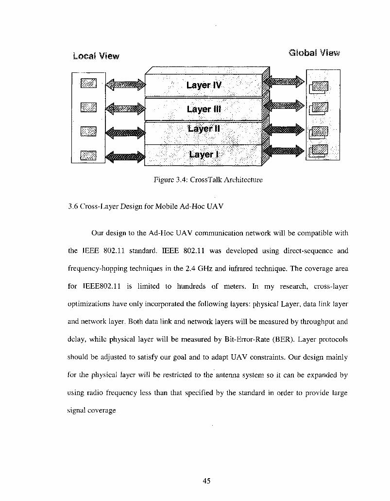
jai View lal vie\
Layer IV
Layer III
Layer II
Layer I
Figure 3.4: CrossTalk Architecture
3.6 Cross-Layer Design for Mobile Ad-Hoc UAV
Our design to the Ad-Hoc UAV communication network will be compatible with
the IEEE 802.11 standard. IEEE 802.11 was developed using direct-sequence and
frequency-hopping techniques in the 2.4 GHz and infrared technique. The coverage area
for IEEE802.il is limited to hundreds of meters. In my research, cross-layer
optimizations have only incorporated the following layers: physical Layer, data link layer
and network layer. Both data link and network layers will be measured by throughput and
delay, while physical layer will be measured by Bit-Error-Rate (BER). Layer protocols
should be adjusted to satisfy our goal and to adapt UAV constraints. Our design mainly
for the physical layer will be restricted to the antenna system so it can be expanded by
using radio frequency less than that specified by the standard in order to provide large
signal coverage.
45

3.6.1 Physical Layer Design
The physical layer of the UAV system will perform a direct sequence spread
spectrum to provide wireless connection to the Ad-Hoc network. Generally speaking, a
spread spectrum modulation technique generates a signal that has a bandwidth much
larger than the original signal. The bandwidth of the transmitted signal is determined by
the message to be transmitted and by an additional signal called pseudo-noise (PN) code.
Spread spectrum systems are classified into different types based on how the original data
is modulated by the PN code. Basically, there are two types of Spread Spectrum
modulation techniques: Frequency Hopping (FHSS) and Direct Sequence (DSSS).
1. Frequency Hopping Spread Spectrum (FHSS): In FHSS, the signal energy is spread
over a wider bandwidth than the information bandwidth. The available bandwidth is
divided into a large number of frequencies that are spaced to prevent interference. The
spreading code in FHSS is the list of frequencies to be used for the carrier signal which is
periodically modified as a result of using a digital frequency synthesizer. A digital
frequency synthesizer is driven by the PN to hop among the previous frequencies. FHSS
is defined in IEEE 802.11 to cover 79 frequencies ranging from 2.402 GHz to 2.480 GHz
with a channel width of 1 MHz.
2. Direct Sequence Spread Spectrum (DSSS): In DSSS, the data signal is multiplied with
a pseudo-noise (PN) code. It uses a technique called chipping in which the modulated
data is spread across the spectrum. The information to be transmitted is divided into small
pieces. Each bit of signal data is spread at the transmitter into L chips, and then the chips
are transmitted at a rate equal to L x bit rate of the data. DSSS can also be used as a
multiple access technique; this multiple access technique is called code division multiple
46

access (CDMA). DSSS is divided by IEEE 802.11 into 14 possible carriers that are 22
MHz wide and covers the range from 2.402 GHz to 2.480 GHz.
The performance of physical layer is mainly affected by the interference as a
result of sharing one channel. DSSS will be used in our system since the transmission
capability of the wireless channel can be maximized by using variable data rate. The
performance is determined based on the following parameters: transmit power,
modulation, coding rate, and antenna beam. Bit error rate (BER) is the key factor to
measure the performance of physical layer. Adaptation of these parameters to achieve the
target BER is the key solution to the Ad-Hoc network. Usually, the BER is calculated by
Signal-to-Noise Ratio (SNR). Increasing SNR in the Ad-Hoc network can improve the
performance and reduce the BER. To satisfy this goal, directional antenna will be used so
that the total gain is responsible for the improvement of the whole system.
3.6.2 MAC Layer Design
As a result of sharing the same channel in Ad-Hoc network, the MAC layer exists
to schedule the transmissions and allocate channels between nodes. The result that may
be gained by scheduling and allocation is to reduce the interference between nodes and
stop concurrent transmissions. On the other hand, the effect of the previous MAC mission
may add a delay to the packet transmission. Thus, designing MAC layer in such systems
brings a high competition between researchers. Meanwhile, The MAC layer needs a new
mechanism to adjust its parameters and to coordinate the available resources that may be
shared by network members. Our system will minimize the time taken as a result of
47

scheduling by switching the transmission between the two types of antenna used by the
UAV.
3.6.3 Network Layer Design
The responsibility of the network layer is to divide the data into small packets and
then add a logical address of the source and the destination. Based on the added address,
the process will continue by acquiring the route that will carry the data packets according
to these addresses. The decision in selecting the route between source and destination
differs from one protocol to another, and thus, the performance of the MAC and physical
layer will be affected [42]. In a UAV Ad-Hoc network, the OLSR routing protocol is
implemented with a slight modification to serve the directional antenna. The decision in
selecting the route will be based on the MPRs that are selected by the UAVs.
3.6.4 System Design
Due to the nature of the UAVs, the local adaptability of the OSI model can not
achieve a certain application requirement, thus, a global adaptability is required where
information is exchanged between layers. In addition, the dynamic state of our network
required a comprehensive adaptation to the aircraft attitude.
As shown in Figure 3.5, our proposed cross-layer design is based on the
interactivity between protocols and the sharing of the following information: Bit-Error-
Rate (BER), aircraft attitude, aircraft locations, retry counter (R), multipoint relay (MPR)
locations and antenna type in use. All of the information is shared and accessed by the
first three layers of the OSI model. The upward-downward arrows indicate that the two
48

layers affect the session during packet transmission, while left-right arrows indicate that
each layer has the capability to fetch and store the needed data. BER will be read as a
result of CTS reception. During the use of Omni-directional antenna, the MAC layer will
switch to directional antenna if the BER gets worse. In addition, it will keep transmission
on Omni- directional as the UAVs are getting close to each other.
Global profile
Figure 3.5: Target-Source Based Architecture
49

3.7 Summary
It is evident that the impact of the aircraft attitude on the performance of the Ad-
Hoc network during the use of directional antenna will be significant. To reduce this
effect, the first three layers in the OS I module should exchange information about the
state of the wireless link. By implementing cross-layer technique in such network we can
make this information available as requested. At the beginning of this chapter, we gave a
brief description for the two most important models used in networking; the open systems
interconnection (OSI) model and the TCP/IP model. Then we discusses some
characteristics that UAV network posses and differs from other networks, such as the
effect of aircraft attitude on the MANRT performance and the effect of the aircraft
fuselage on the antenna system. These characteristics are making the models mentioned
above inefficient and not effective in such networks. At the end of this chapter, we
present two architectures that are published for the Ad-hoc network, those are
architectures that based on local profiles and architectures that based on global and local
profiles; last we present our new architecture that is called Target-source Based
Architecture.
50

CHAPTER IV
MAC SCHEME FOR MOBILE AD-HOC UAV USING DIRECTIONAL ANTENNA
In this chapter, we address the effect of using directional antenna on the Medium
Access Control (MAC) layer. With directional antenna, higher gain allows UAV to
communicate with other UAVs located at higher distance in fewer hops. On the other
hand, the high mobility as well as the physical constraints imposed by a UAV may cause
the use of directional antenna to be less beneficial and meaningless. In this respect, we
have designed a new scheme that has the capability of benefitting from the directional
antenna and at the same time is capable of handling the above issues. Our scheme is
based on the following two performance goals: maximizing network throughput and
minimizing End-to-End delay.
4.1 Introduction
Recently, UAV has been used in military applications as well as civilian [21]. It
shows great advantages and importance in search and rescue, real time surveillance,
reconnaissance operations, traffic monitoring and range extension. Moreover, UAVs are
suited for situations that are too dangerous for direct human monitoring. In general,
UAVs have the potential to create an Ad-Hoc network and greatly reduce the hops from
source to destination. On the other hand, UAVs are characterized by high mobility and
attitude variations.
It assumed that in all of the UAVs used in communication networks, each node is
equipped with Omni-directional antenna in which signal is transmitted to all directions.
51

As a result, the capacity of the network and the range of the UAVs are common problems
for UAV mobile Ad-Hoc networks. These problems can be largely eliminated by using
directional antenna [6, 7, 22, 23, 24]. In this chapter, we considered a collection of UAVs
that communicate through a wireless link such as MANET using directional antenna. The
current MAC protocol (IEEE 802.11) that implements the Omni-directional antenna may
not be suitable while using directional antenna. Thus, a new adaptive medium access
control protocol is required to adapt the new technique as well as the constraints imposed
by the UAV. To be more specific, we introduced a new mechanism that is called target
information table (global profile) to work with our new MAC scheme during the switch
from Omni-directional to directional antenna.
The primary challenge to use directional antenna in such network is the errors in
UAV position; this leads to the reduction of the directivity in the desired direction.
Therefore, a combination of more than one navigation system is the central requirements
for a practical solution to the UAV communication system. As is known, GPS provides
position information at (1) second interval, this interval will not benefit our scheme since
our scheme needs a higher update rate for the position of the UAV. As a result, each
UAV should be equipped with a GPS and an Inertial Measurement Unit (IMU) to offer
the positions of other UAVs [1, 20, 33]. The benefit of using an IMU with a GPS is that
the IMU may be calibrated by the GPS signal, and thus, it can provide position and angle
at a quicker rate than GPS.
52

4.2 Medium Access Control (MAC) Layer Description
The IEEE 802.11 standard [100] specifies the parameters for the medium access
control as well as those for the physical layer. It assumes the use of Omni-directional
antenna and provides the functionality required to guarantee a reliable data transmission
over a wireless media. In the following subsections we will focus on the mechanisms that
are used by the MAC layer for the purpose of channel allocation, frame formatting, error
checking and fragmentation. Meanwhile, we will study the effect of directional antenna
on the performance of this layer.
In IEEE 802.11 standard, wireless MAC protocol is supported by a Carrier Sense
Multiple Access with Collision Avoidance (CSMA/CA). CSMA is a technique used by
wireless/ wired network for performance improvement. To summarize CSMA, A node
wishing to send a data packet should first listen to the medium to see if there is any
activity. If the medium is sensed as idle for a Distributed Inter-Frame-Space (DIFS)
interval, the node has the right to use the medium and start sending data. On the other
hand, if the medium is sensed as busy or it becomes busy during the DIFS time interval,
the transmission will be deferred for a certain time (random) until no other node occupies
the medium.
Two different network architectures are specified by IEEE 802.11 standard: Ad-
Hoc and infrastructure networks. In an Ad-Hoc network, there is no fixed infrastructure
such as base station or access point (AP). Nodes in Ad-Hoc network are communicating
directly via a wireless link, while in infrastructure network they are communicating
through the access point. In addition, IEEE 802.11 standard specifies two access
53

methods (MAC protocols): Distributed Coordination Function (DCF) and Point
Coordination Function (PCF). DCF is considered as the basic access method and it is
used in Ad-Hoc network while PCF is used in an infrastructure network.
4.2.1 Distributed Coordination Function (DCF)
DCF is considered as one of the main access mechanism in IEEE 802.11 MAC
layer. This mechanism determines when and how to access the wireless channel and it
has been used to support asynchronous data transfer. DCF employs the Carrier Sense
Multiple Access / Collision Avoidance (CSMA/CA) with a random backoff and it
specifies two mechanisms for channel sensing: physical carrier sense mechanism and
virtual carrier sense mechanism. Physical carrier sensing is performed at the physical
layer while virtual carrier sensing is performed at the MAC layer in which Request-to-
send (RTS) and Clear-to-send (CTS) frames are exchanged between source and
destination. Also DCF specifies a positive acknowledgment scheme that is transmitted by
the destination to notify the source node of the successful reception.
Physical carrier sensing is used in Ad-Hoc network to mitigate the interference
between nodes. A node wishing to transmit a packet should first assess the current
channel by comparing the measured received energy against a predefined threshold. If the
node detects that the value of the comparison is below a certain threshold, the node will
start packet transmission. Otherwise, transmission will be deferred. As we will see later,
OPNET simulator allows the node to generate an interrupt whenever it transmits a packet.
This interrupt tells other nodes when transmission started and finished.
54

Virtual carrier sensing is performed by exchanging request-to-send and clear-to-
send frames between source and destination. In DCF, Each node should embed the period
of transmission in the header of the RTS and CTS frames. Upon receiving either of these
two control packets, the node should extract the duration and store it in a local variable
named Network Allocation Vector (NAV). This value shows that the channel is busy and
the node couldn't access the medium. By this mechanism, the transmission should be
deferred for the duration of the data frame that will follow.
As soon as the node senses that the channel has been idle for a period of time that
exceeds the DIFS interval, the node starts packet transmission. Otherwise, packet
transmission will be deferred for a period of time named Backoff. The length of the
Backoff period is calculated by equation (4.1). The random number in the equation is
selected randomly between zero and the contention window value size (CW) [0: CW].
Initially, the size is set to its minimum value (CWmin). If a collision has occurred, the
size will be doubled. Table 4.1 shows the values for both the CW and slot time.
Backoff time= Random number X (slot time) (4.1)
In wireless network, a collision is considered if the node does not receive an
acknowledgment (ACK) packet from the destination node. As a result, contention
window size is doubled for the next transmission attempt. It continues to increase to the
CWmax. In DCF, transmission attempt is bounded by a certain number, if the attempts
reach this number, the packet will be dropped. Meanwhile, if the medium has been
sensed as idle for a DIFS, the timer will be decreased by one. As soon as the backoff
timer becomes zero, the source node transmits the packet. The destination node will
55

respond with an ACK message to the source node after a period of time called Short
Inter-Frame Space (SIFS) interval. Figure 4.1 shows the IEEE 802.11 DCF Mechanism.
DIFS SIFS
RTS
SIFS •4 •
CTS
•4 • DATA
SIFS
ACK
Figure 4.1: IEEE 802.11 DCF Mechanisms
4.2.2 Point Coordination Function (PCF)
Point coordination function is the second MAC technique specified by
IEEE.802.11 standard. It is implemented by the point coordinator (PC) to coordinate the
communication between the nodes within the network. Accessing wireless channel in
PCF is a centralized method. PC sends a contention-free (CF-Poll) frame to the node
giving it the permission to transmit a frame. If the polled node does not have any frames
to send, null frame is transmitted. The period used by the access point to grasp the
channel is called Point Coordination Function IFS (PIFS). PIFS period is smaller than
DIFS because the AP always has the priority to access the channel.
As stated above, there are two modes of operations supported by the IEEE802.11
standard: infrastructure and Ad-Hoc. PCF is supported by the infrastructure mode of
operation. Nodes in this technique are allowed to send their data only when they receive
the polling frames from the point coordinator. In contrast to the DCF technique, nodes in
56

PCF are able to transmit without contending for the channel access. The point coordinator
determines which station should be polled and which station has the right to transmit.
PCF has its location above the DCF in MAC layer, and it is an optional access method.
4.2.3 Inter-Frame-Space (IFS)
In DCF, the gap in time between frames is called Inter-Frame-Space (IFS). Each
station should determine if the medium is idle through the use of the physical carrier
sensing mechanism for the intervals specified in table 4.1. In this table, four different
periods are defined to provide priority levels for accessing the wireless channel: Point
Coordination Function IFS (PIFS), Distributed Coordination Function IFS (DIFS), short
IFS (SIFS) and extended IFS (EIFS).
1. PIFS: This interval should be used only by those nodes implementing the PCF
mechanism to gain the access to the medium at the start of the contention-free period
(CFP).
2. SIFS: It is considered as the shortest of the inter-space intervals. IEEE.802.11 standard
has specified this period as the end of the last symbol of the previous frame to the
beginning of the first symbol of the preamble of the next frame. This interval prevents
other nodes from attempting to use the medium during the whole phase of exchanging
data between two nodes, and thus giving priority to the source and destination to
complete the exchange of their data.
3. DIFS: This interval should be used only by those nodes implementing the DCF
technique. In the basic access method, as soon as the station senses the channel is idle,
57

the station waits for DIFS period and start sending their data. DIFS is calculated as shown
in equation (4.2).
DIFS = SIFS + 2 X (slot time) (4.2)
4. EIFS: This interval should be used by the DCF whenever the physical layer has
indicated to the MAC layer that there has been an error in frame transmission. EIFS is not
used to control access to the radio link. But, if previously received frame contains error,
the node has to defer for EIFS duration instead of DIFS before transmitting a frame.
EIFS = Transmission time of (Ack) frame at lowest basic rate + SIFS + DIFS (4.3)
Table 4.1
Inter-Frame-Space Intervals
Frequency hopping (FH)
Tslot=50 us SIFS= 28 us CWmin= 15 CWmax=1023
Direct-Sequence Spread Spectrum (DSSS)
Tslot=20 us SIFS= lOus CWmin=31 CWmax=1023
Infra red
Tslot=8 us SIFS= 10 us CWmin= 63 CWmax=1023
4.3 Physical Layer Description
As shown in table 4.2, The IEEE 802.11 standard defines the physical layer
specifications that are mainly comprised of modulation type, frequency, channel
bandwidth and transmission power. It specifies three physical layer technologies:
Frequency Hopping Spread Spectrum (FHSS) physical layer, Direct Sequence Spread
Spectrum (DSSS) physical layer and infrared physical layer. The IEEE 802.11b physical
layer, as in other protocols, consists of two sub-layers: Physical Layer Convergence
58

Procedure (PLCP) and Physical Medium Dependent (PMD) sub-layers. The PLCP sub
layer is used to prepare the MAC Protocol Data Unit (MPDU) for transmission. It is also
used to deliver the incoming frames from the wireless medium to the MAC layer. PMD
sub-layer interfaces directly with the air medium and it is responsible for the modulation
and demodulation of frames.
Table 4.2
IEEE 802.11 Physical Layer Standards
Bandwidth
Frequency
Data rate
802.11
83.5 MHz
2.4 - 2.4835 GHz DSSS, FHSS
1,2 Mbps
802.11a
300 MHz
5.15-5.35 GHz OFDM
5.725 - 5.825 GHz OFDM
6,9,12, 18,24, 36, 48, 54 Mbps
802.11b
83.5 MHz
2.4 - 2.4835 GHz DSSS
1,2,5.5, 11 Mbps
802.11g
83.5 MHz
2.4 - 2.4835 GHz DSSS, OFDM
1,2,5.5,6,9, 11, 12, 18,24,36, 48, 54 Mbps
4.3.1 Antenna Basics
Antenna is a metallic device that is designed for radiating or receiving radio
waves. To choose an antenna for a radio communication system, several important
parameters should be considered. The most important are antenna radiation pattern and
gain. Antenna radiation pattern can be defined as a plot of the strength of the
electromagnetic field in all directions around the antenna while antenna gain is the ratio
of the radiation intensity in a specific direction to the radiation intensity of the ideal
isotropic antenna. The two important types of antennas are the isotropic Omni-directional
59

antenna and the directional antenna. Isotropic antenna radiates and receives power
equally in all directions while directional antenna focuses energy in the desired direction.
Directional antennas as we will see in the next sections are usually used in some
applications to cover long distances. Figure 4.2 shows the patterns for the omni
directional antenna and directional antenna; the antenna pattern on the left represents the
isotropic omni-directional antenna while the antenna pattern on right represents the
directional antenna.
Figure 4.2: Typical Radiation Pattern for Omni-Directional and Directional Antennas
4.3.2 Modeling Smart Antenna
Smart antennas are a promising technology nowadays to address the demand of
UAV wireless communication systems in terms of capacity and area coverage. Simply,
smart antenna is an array of (N) antenna elements that act together to form the required
radiation pattern. This type of antenna is capable of changing its radiation pattern
dynamically in order to adjust to the variations in channel's noise and interference. Due
to the high mobility of the UAV, the direction between aircrafts will be continually
changed. Exploiting smart antenna in UAV Ad-Hoc network requires an intelligent
60

system to decide when and where to point the antenna pattern. In our system we assumed
that each UAV is equipped with four antennas, two of them are directional antennas
(steerable antenna) and two of them are Omni-directional antennas. Smart antennas in
general are classified into two categories: switched beam and adaptive array.
1. Switched-beam antenna: As shown in figure 4.3, a switched-beam antenna system
consists of several fixed, predefined beams. Switched-beam antennas are less complex
than the adaptive antenna and are easier to implement because they need only a basic
switching functionality between separate directive antennas. The number of beams in
switched-beam antenna is limited to a certain number and only one antenna can be used
at any given time. This type of system switches the beams toward the strongest signal but
does not actively null out the interference.
Figure 4.3: Switched Antenna with Six Elements
2. Adaptive array antenna: As shown in figure 4.4, an array of more than two antennas
can be arranged spatially in a certain way to generate the required radiation pattern (The
array may be circular or linear). This system is able to form multiple main lobes in the
desired directions and steering nulls in the direction of interference. Simply, the phases of
61

the exciting current in the array are adjusted so that the maximum or null pattern is
created. Adaptive array is more beneficial than switched beam but it is highly complex in
reality. Adaptive array also allows the node to communicate with two or more nodes
using the same frequency.
User2 Userl
Figure 4.4: Antenna Pattern of Adaptive Array
To illustrate how the radiation pattern is calculated, assume that we have (i)
elements of an array receiving signals from (1) sources, the received signal can be written
as shown in equation (4.4) where the Au is the signal strength and the Pu is the phase lag.
The total signal received from the (1) sources is shown in equation (4.5). To find the
output y in the direction of (1), we have to multiply equation (4.5) with the weighting
coefficient W as shown in equation (4.6). From equation (4.6), the gain of the antenna in
the direction of (1) is seen in equation (4.7).
jwt Ku=AaxPaxe
y^ktxW,
(4.4)
(4.5)
(4.6)
62

If i= 1, we can rewrite equation (4.7) in a matrix form as shown below
~G;
•
G i .
—
Pn •
A
•
•
•
Pu •
p«.
x •
x To find the radiation pattern in particular direction, W matrix should be calculated as
shown below.
X •
X -
~Pn •
Pn
•
•
•
Pu •
Pu.
-1
X •
X
4.3.3 UAV Antenna System
We have constructed our directional antenna pattern in Optimized Network
Engineering Tool (OPNET). Figure 4.5 shows the OPNET interface window used to
create the pattern of the directional antenna. The maximum gain in the pointed direction
is set to 200dB and -12dB in other directions. The beam width is set to 5 degrees .The
novelty in our antenna system relies on designing a new MAC protocol that is capable of
switching between two directional antennas. Figure 4.6 shows the first antenna that is
mounted at the top of the UAV and the second antenna that is mounted at the bottom of
the UAV. In our modeling of the antenna system, there are two modes of operations:
directional and Omni-directional. In directional mode, antenna consists of a steerable
single beam which is dedicated for data transmission, while in Omni-directional mode;
antenna is dedicated for control packets. Selection between directional antenna will rely
on the altitude of the aircrafts and on the value of the retry counter within the MAC layer.
63

File Edit Antenna Windows Help
IPS &
-12-
<
m gah ijheta) (t») | pH = 10 (deg)
« » a B « B a o a B a a a » B B a » » B B » B «
J SO 100
a a a a a n a a a a
150
" « " • « • » " " *
200 -
• • • » • « " • « •
250 :
» « B a a » t ) B B
> '• 300-
B B S B n a f l g
350
mi
Figure 4.5: Modeling Directional Antenna in OPNET
Dl D2
Figure 4.6: Coverage Range of MAC Protocol Using an Omni-Directional and Directional Antenna
Generally speaking, there are many parameters that affect the value of the
received power. Assume that the gain of the Omni-directional antenna is (G0) and the
gain of the directional antenna is (Gj). Friis equation (4.8) represents the relation between
gains of both transmitter and receiver antenna, and transmitter and receiver power.
64

P A ^ — = GtGr
P
(4.8) KA7tRj
Where Pr represents the received power and P, represents the transmitted power. G, and
Gr are the antenna gain of the transmitting and receiving nodes, X is the wavelength, and
R is the distance between the transmitter and the receiver. From the equation, the distance
between any two nodes is proportional to the gains of transmitter and receiver antenna.
For directional antennas, the gain is formulated as a function of the direction of the
destination node 3 = {q>,G) and is given by equation (4.9).
G(D)=K Y(D)
K J (4.9)
Where Y(D) is the power density in the desired direction D . Yp is the average power
density over all directions and K is the efficiency of the antenna that accounts for losses.
In general, the gain of the directional antenna measures the relative power in one
direction compared to an Omni-directional antenna.
The received signal Y (t) can be modeled in terms of the transmitted signal and the
background noise. Assume that UAVi and UAVj are in communication session. The
signal received by UAVs is given by equation (4.10).
Y(t) = WH yX(t) + N(t) (4.10)
Where X(t) is the transmitted signal, W is the weighted vector, which represents the
antenna elements in use , for example , two antenna represented by [1,1] , H^ is a
matrix that models the physical channel between the UAVs, and ,/V(t) denotes additive
white Gaussian noise.
65

4.4 Adaptive MAC Protocol for UAV Node (AMAC_UAV)
The performance of the unmanned aerial vehicle Ad-Hoc network depends on
several factors such as mobility and aircraft attitude. We assumed that all UAVs are
placed over the ground and flown at different altitudes. The distance between any two
UAVs will not go beyond the range of the directional antenna. Two externals hardware
are needed in our scheme for node location: GPS and IMU. When a packet comes from
the upper layer, the node requires the position of the destination in order to steer the main
lobe in the right direction. Control packet of type RTS will be sent using Omni
directional antenna; it should include the position of the aircraft and duration of
transmission. On the other hand, the destination node will respond with a CTS packet that
has the same information regarding itself. Each node that hears the CTS or RTS should
cache this information and update its table for future use. The data packet will be sent
using directional antenna. To simplify things, we presented our scheme in Figure 4.7
based on the following facts:
Case A: Every UAV has four antennas. Two of them are directional. One is located
above the UAV and marked primary, and the second one is located beneath the UAV and
marked secondary. The two other antennas are Omni-directional. If the UAV has no
packet to send, it will listen to other UAVs using one of the Omni-directional antennas.
On the other hand, if the UAV has a packet to send, it has the choice to send this packet
either using directional or Omni-directional antenna.
Case B: The locations of the UAVs are significant factors in our scheme. The new MAC
should frequently monitor the positions of other UAVs and compute the effect of Euler
angles on the directional antenna.
66

Case C: The new MAC should frequently monitor the distance, bit error rate and retry
counter so that it switches to Omni-directional antenna if the values exceed the limits.
Case D: In the case that there is no activity during a second, UAV should send a
heartbeat message using Omni-directional antenna. This message contains the location of
the UAV. When it is received by another UAV, the UAV should update its table and
respond with a similar heartbeat message.
Case E: In our scheme each UAV is capable of electronically steering the beam towards
a specific direction. Our modeling of the antenna is described in section 4.3.3 and is
based on a single beam that can target the boresight to any direction.
Case F: In the case that the aircraft changes its attitude, the pattern of the antenna will
rotate with respect to its axis, resulting in fluctuations in antenna gain, these fluctuations
affect the range of the UAV. Thus, the MAC protocol should compensate for any changes
by applying the same value to the target location.
Case G: Switching time between primary and secondary antenna is assumed to be zero.
Case H: The mobility model in such a network is not completely random. In military
scenarios, each UAV should move to a predefined location. Thus, our model is based on
a rounded rectangle [32] mobility model. Section 4.5.3 will give more detail for the
mobility models.
According to the IEEE 802.11 standard, a packet is discarded after the retransmit
counter exceeds (7). Meanwhile, as the number of retransmission attempts increases, the
number of possibilities for delay increases. Based on the Distribution Coordination
Function (DCF), a node should sense the channel to determine whether it is idle or not.
Sensing is done through physical and virtual mechanisms. If the medium is sensed idle
67

for a DCF inter-frame-space (DIFS) interval, the node has the right to use the medium
and start sending data. On the other hand, if the medium is busy or it becomes busy
during the DIFS time interval, the transmission will be deferred for a certain time until no
other node occupies the medium. In such a situation backoff timer is enabled. Our
scheme follows the IEEE 802.11 standard with some modification to the retry counter.
As stated in section 4.2.1, there are two methods for carrier sensing in IEEE
802.11 standard, physical carrier sensing and virtual sensing. Virtual sensing is done
through the use of network allocation vector (NAV). Two messages should precede the
data transmissions which are RTS and CTS, these messages contain the duration for
which the UAV should reserve the channel to complete the data transmission. On the
other hand, any UAV that overhears these messages should defer data transmission for
this duration to avoid interfering with other UAVs' transmission. In our scheme, RTS and
CTS should contain the location and orientation of the UAV. We use the directional
network allocation vector (DNAV) mechanism [27] with some modification to adapt our
scheme while using UAVs. Our DNAV is synchronized with the target information table
that is created through the handling of the control messages. In addition, the original
NAV is also used in our scheme.
The behavior of our scheme works as follows:
1) To resolve the hidden terminal problem, a CTS/RTS packet is exchanged between the
UAVs. Consider the case when UAV number one is attempting to send a packet to UAV
number two: if the packet is of type control, UAV number one will perform physical
carrier sensing as in IEEE 802.11 standard. If the channel is idle, another sensing will be
done for NAV to see if the channel is still reserved by another UAV. Once the medium as
68

well as the NAV are all idle, the UAV will enter the backoff period for a certain time
then RTS packet will be sent through the Omni-directional antenna along with the
parameters of UAV number one (location, orientation).
2) UAV number one as well as number two are equipped with a GPS and IMU to offer
the position at high rates. Once the UAV number two receives RTS from UAV number
one, it will sense the channel for short inter-frame-space (SIFS) interval. If the channel is
free, it will send the CTS along with the previous parameters in response using omni
directional antenna and update the target information table as shown in table 4.3. UAVs
other than number two that also received either RTS or CTS should update their target
information table as well as DNAV and NAV.
3) Once UAV number one receives the CTS message, it will update its target information
table. Before initiating the transmission of data packet, the MAC will check the distance
between the UAVs. If the distance is less than the range of the Omni-directional antenna
(Dmax), the data will be sent using Omni-directional antenna; otherwise the MAC will
check UAVs' altitude. If the altitude of UAV number one is equal or less than that of
UAV number two, data will be sent through the primary antenna (directional antenna)
along with UAV parameters then the MAC steers the beam to the direction of UAV
number two, otherwise secondary antenna will be steered to the same direction.
4) As soon as UAV number two receives the data successfully and updates its target
information table, ACK will be sent using Omni-directional antenna along with UAV
parameters.
5) For each data packet, antenna is steered based on the destination location as well as the
source Euler angles. To be more specific, consider UAV number one's attempt to send
69

the second data packet. The location of the UAV number two is obtained from the ACK
packet. If the MAC of the first UAV sensed some changes in the angles after receiving
the target location, the MAC should compensate for this by applying the same value to
the target location.
6) As mentioned above, a packet is discarded after the retransmit counter exceeds (7).
Since our goal is to minimize the End-to-End delay, our scheme will switch the
transmission from directional to Omni-directional if the retransmit counter reaches five.
Yes
Yes
Fail
Send omni
Pass Yes
Yes
Packet to be sent
-* BackOff T
_ Channel ~~~ busy
No
Pck==Controi
• Target Info
No
Send secondary
AnB1(l-1) N o
== -* Anglit)
No
| Compensator
Fail
Pass
D<Dmax
t No
Alt1>=Alt2
No
•+< R > = 5 •+-
T Yes
~Send omni
Yes
Pass
AnH1(l-1)
Ang1(t)
No
[ Compensator
Fail
Yes
Send Primary
Pass
Update Target Information Table Figure 4.7: MAC Scheme Flow Chart for UAV
70

Table 4.3
Target Information Table
Target ID
1 2
Latitude (Deg Min Sec)
43 16 32 N 43 16 32 N
Longitude (Deg Min Sec)
85 38 46 W 85 38 36 W
Altitude (Feet)
500 450
Direction (Deg)
90 90
4.5 UAV Implementation in OPNET
4.5.1 OPNET Modeler 14.5
The Optimized Network Engineering Tool (OPNET) modeler is considered as one
of the powerful software simulation tools, it is dedicated for network research and
development. The OPNET modeler software is a discrete-event network simulator that
includes a set of detailed models for Ad-Hoc network. It uses graphic user interfaces and
allows the user to create new models by either modifying existing models or building
new one. It uses a Finite State Machine (FSM) model in which a collection of states are
linked together based on C code. Each state is divided into two parts: enter executives
and exit executives. Both parts specify a series of actions that a process implements when
it occupies a state. The enter executive is executed as soon as the state is entered by the
process while the exit executive is used in the unforced state to implement a response to
an interrupt.
71

4.5.2 Channel Model
In our simulations, we modeled the wireless link between transmitter and receiver
with fourteen pipeline stages. These stages are provided by the OPNET modeler and
divided between transmitter and receiver as shown in figure 4.8. Six stages (0-5) are
associated with radio transmitter and eight stages (6 -13) are associated with radio
receiver. Below is a description for all stages.
1. Receiver Group (Stage 0): This stage is called only once for each pair of transmitter
and receiver channels in the network; by this stage every transmitter maintains a set of
channels that are going to receive its transmission. The purpose of this stage is to model
the broadcast nature of the radio by creating links between one transmitter and a set of
receiver channels with which it is allowed to communicate.
2. Transmission Delay (Stage 1): This stage is the first stage of the pipeline. It is called
immediately as soon as the transmission of a packet is started. It is used to calculate the
amount of time that is required for the packet to be transmitted. The output from this
stage is computed as the time difference between the beginning of transmission of the
first bit and the end of transmission of the last bit and is assigned to the variable
(OPC_TDA_PT_TX_DELAY). Another method for calculating this value is dividing the
packet's length by the data rate. This result is then used by the Simulation Kernel in order
to schedule the end of transmission event for the channel that is used for transmission. As
soon as this event happens, the transmitter channel becomes idle and starts sending
another packet if it has any. In addition, the output from this stage is added to the output
of the propagation delay stage in order to compute the time at which the packet completes
reception at the other side.
72

3. Closure (Stage 2): This stage is called immediately after the end of the transmission
delay stage 1, closure here means the ability of the transmission to reach the receiver
channel .The purpose of this stage is to determine whether or not the transmitted signal
can physically reach the receiver channel.
4. Channel Match (Stage 3): In this stage, transmission is classified with respect to the
receiver channel into three types: (a) valid: packet is classified as valid if the transmitter
and receiver channels are in agreement on the values of certain key attributes, (b) Noise,
packet is classified as noise if the transmitter and receiver channel configurations are
incompatible, (c) Ignored: packet has no effects on the state of the receiver channel.
5. Transmitter Antenna Gain (Stage 4): In general, antennas are classified into directional
and isotropic. Isotropic refers to the antenna that provides no gain to the transmitted
signal while directional refers to the one that provides gain to the signal. The word gain
itself is defined as the ratio of the power that is produced by the antenna at a given
distance and the isotropic power produced at the same distance. This value is unit-less
and given in decibels. The purpose of this stage is to compute the gain value of the
antenna attached to the transmitter. This value is used in the calculation of the received
power. Simply, the gain is calculated based on the direction between the transmitter and
the receiver and the antenna attributes: target latitude, target longitude and target altitude.
6. Propagation Delay (Stage 5): This stage is invoked after the simulator returns from the
transmitter antenna gain stage. The output from this stage represents the time required for
the packet to travel from the source to the destination and is assigned to the variable
(OPC_TDA_PT_PROP_DELAY). The value of this variable depends on several
parameters such as: physical medium, distance and frequency. This value is used by the
73

simulation kernel to schedule the beginning of the reception event for the destination
node. In addition, as stated above, this value is used in conjunction with the result from
stage 1 to compute the time at which the packet completes reception.
7. Receiver Antenna Gain (Stage 6): This is the first stage that is associated with the
receiver and it is invoked at the time that the leading edge of the packet arrives at the
destination. The purpose of this stage is to compute the gain of the antenna attached to
the receiver. The process for calculating the gain is identical to that presented in stage 4
where it is used in the calculation of the received power.
8. Receiver Power (Stage 7): This stage is invoked after the simulator returns from the
receiver antenna gain stage; it is used to compute the power of the arriving packet's
signal. The value of the received power depends on transmitter power, distance between
the nodes (r), wave length, and transmitter and receiver antenna gains as shown in
equation (4.11).
p = p XQ X{ X\ )XQ (4.11)
9. Background Noise (Stage 8): This stage is used to represent the effect of all noise
sources on the arriving packets. The result is the sum of the power of noise sources such
as thermal noise, emissions from neighboring electronics, and un-modeled radio
transmissions. This value is later used to find the signal-to-noise ratio.
10. Interference Noise (Stage 9): This stage is responsible for the interaction between
concurrent transmissions that arrive at the same receiver channel. This value is used later
to decide whether to accept or reject the packet at the last stage.
11. Signal-to-Noise Ratio (Stage 10): The purpose of this stage is to calculate the SNR
associated with the arriving packet. Part of the calculation in this process is based on
74

previous values from stages 7, 8 and 9. This stage is significant because it determine the
ability of the receiver to correctly receive the packet's content. The value of the SNR is
stored to be used latter by other stages.
12. Bit-Error-Rate (Stage 11): This stage is intended to derive the probability of bit errors
during the past interval of a constant SNR. The value provided by this stage is calculated
based on the received power value calculated in stage 7 and on the value of Signal-to
Noise ratio calculated in stage 10. This value is stored in OPC_TDA_RA_BER to be
used later.
13. Error Allocation (Stage 12): This stage is invoked immediately after the end of the
Bit-Error-Rate stage. Its purpose is to estimate the number of errors in a packet and it is
used to update the Bit-Error Rate (stagell).
14. Error Correction (Stage 13): This stage is invoked when the packet is completely
received. The purpose of this stage is to determine if the arriving packet is accepted or
not so that it can be forwarded to the receiver's modules. This stage is based on two
factors: the result from stage 12 and the ability of the receiver to correct the errors in the
affected packet. The decision taken in this stage will be passed to the kernel so that it
destroys the packet, or allows it to proceed into the destination node.
75

*77
i Transmitter
Transmission Delay
Receiver Antenna Gain
J Receiver Power
Error Allocation
I Error Correction
Receiver Group
Closure
Propagation Delay
Background Noise
Bit-Error-Rate
i» S
Receiver
Channel Match
J-Transmitter
Antenna Gain
Interference Noise
I Signal-to-Noise
Ratio
Figure 4.8: OPNET Radio Transceiver Pipeline Stages
4.5.3 UAV Mobility Model
The movement of the UAV has a significant influence on the performance of the
network. Therefore, much research was devoted to build different mobility models that
are suitable for evaluating the performance of the Ad-Hoc networks. A large number of
mobility models were introduced; they have different properties and each has its own
76

advantages and disadvantages. In general, the mobility model of the node in a MANET
can be classified into two types:
1. Stochastic mobility models.
2. Realistic mobility models.
In stochastic mobility models, the mobile nodes move randomly and freely
without any constraints. Speed, direction and destination addresses are chosen randomly
and independently. One type of stochastic mobility model is shown in figure 4.9. This
model is called random way point. In random way point, the node randomly chooses a
destination and a random speed distributed uniformly in the interval [0, Vmax]. As soon
as the node reaches the first destination with the selected velocity, it pauses there for a
certain random time. The random time is uniformly distributed in [Tmin, Tmax], then the
node moves towards the new random destination with a random velocity. The node will
keep doing this procedure until the end of the simulation time. Recent research modifies
this procedure by assuming that the pause time is equal to zero and the initial velocity is
equal to Vmin.
Figure 4.9: Mobility Model of the UAV in Random Way Point Method
77

Another type of stochastic mobility model is the random walk mobility model;
this model is close to the random way point so it can be considered as a random way
point with zero pause time. The nodes in random walk model change their speed and
direction randomly. Each node chooses a random direction that is uniformly distributed
within the range [0, 2tt], and also choose a random speed that is also uniformly
distributed [Vmin, Vmax]. The node then moves for a certain period of time or over a
fixed distance with the chosen speed; at the end of this interval the node repeats the
procedure with a new random direction and speed.
The last type is the random direction model which is also considered as a special
type of the random way point. In this type, the node chooses a random direction and
travels with a random speed until it faced an edge then it chooses another direction and
repeats the procedure.
As the random way point, the random walk model and the random direction
model are just unrealistic model, the velocity of node is a memory-less random process in
that the current speed is independent of the previous one. Thus, a sudden stop,
acceleration and sharp turn may frequently occur during the mobility of the node. On the
other hand, the real life scenarios assumed that the speed of the node is accelerated
incrementally and the direction is changed in a smooth manner. Also the previous models
are sometimes called entity mobility model in that the node moves freely and
independently of other nodes which totally contradicts the movement of the UAV in the
military scenarios. Any node in military scenarios is moved in a predefined trajectory so
that the movement is not completely random.
78

Smooth random mobility model and Gauss-Markov mobility model are classified
as realistic mobility models. In smooth random mobility model, the mobile node changes
its speed and direction in a smooth way where the parameters are changed gradually.
Each node is characterized by a motion vector (V, O), V is the speed of the node and O is
the direction. The following equations show how the motion vector and the position of
the node are updated (every At) in such a model.
X(t + At) = X(t) + V(t) x COS(0(t)). (4.12)
Y(t + At) = Y(t) + V(t) x SIN(0(t)).
<p(t + At) = (pit) + A(0)).
(4.13)
(4.14)
The mobility model for UAV should be close to the real life. In this chapter, we
model the mobility of the UAV with six parameters (pitch, roll, yaw, latitude, longitude
and altitude). Each UAV is moving in a pentagon route as shown in Figure 4.10 where X
represents the start location of the UAV. The route of the UAV will continue to point B
with a constant speed and zero pitch, zero yaw, zero roll. For each segment we changed
one parameter, table 4.4 shows the parameters in more details.
B
D
Figure 4.10: UAV Mobility Model in OPNET
79

Table 4.4
UAV Mobility Parameters
segment AB BC CD DE EF FA
Latitude B C D E F A
longitude B C D E F A
altitude 500 500 500 500 500 500
pitch 0.0 1.0 0.0 0.0 1.0 0.0
roll 0.0 0.0 1.0 0.0 0.0 1.0
yaw 0.0 0.0 0.0 1.0 0.0 0.0
4.5.4 Modeling UAV with Two Directional and Two Omni-Directional Antenna
As shown in Figure 4.11, UAV is modeled according to the OSI stack. Some
layers have been omitted and some modifications were added to the original modules.
The UAV model consists of three main sections: physical layer, data link layer and upper
layers. The first part represents the physical layer; this part is slightly different from the
OPNET standard model. As shown in the figure, the physical layer is composed of
transmitter module, receiver module and antenna module. In UAV modeling, we have
used three transmitters, one receiver and four antennas. One Omni-directional antenna is
connected to the receiver module and three antennas are connected to the transmitter
modules, one of them is an Omni-directional antenna while others are directional antenna.
All of the above modules are responsible for the wireless communication between UAVs.
The second part is the data link layer. This part is divided into two modules: the
first one is the original MAC module (wireless_lan_mac) and the second is our module
(UAV_SUB_MAC). The wireless_lan_mac module implements the MAC protocol
defined by the IEEE 802.11 standards. This module is designed mainly to be used with
80

Omni-directional antenna. Some modifications have been done to this module in order to
link the directional antennas with the radio transmitter modules and enabling this module
to work as a two mode module. The second module implements our scheme described in
section 4.4 and it acts as an interface between the wireless_lan_mac and the lower layer
modules. Both modules work jointly to serve our new scheme.
The last part is the upper layers. The upper layers are mainly composed of the
following modules: ARP module, IP module, IP_ENCAP module, TRAF_SRC module,
UDP module, DHCP module, MANET_RTE_MGR module and CPU module. These
modules mainly generate data packets and implement the OLSR routing protocol. For
example, TRAF_SRC module performs the function of generating raw packets. These
packets are simply unformatted bits which are encapsulated as IP datagram by the
IP_ENCAP module. The IP module implements the IP protocol and the
MANET_RTE_MGR module implements the OLSR protocol and manages the statistics
for simulation runs.
As discussed earlier, the UAVJSUBJVIAC module will work jointly with the
wirless_lan_mac module. Figure 4.12 shows the process model for the UAV_SUB_MAC.
The process is constructed by seven states where the numbers in parentheses give an
approximate number to the line code used in each state. Below is the function of each
state.
Init state: This state initializes state variables and target information table.
Idle state: This is the default state. The node enters an idle state and waits for an
incoming event. The event can be either self interrupt or an incoming packet from the
wirless_lan_mac module. An incoming packet from the wirless_lan_mac will be checked
81

based on its type; control packets will be sent to the Omni state while data packets will be
sent to target table state. In addition, this state will read the initial parameters that affect
the selection of antenna as well as the MAC attribute values.
Omni state: In this state, the incoming packet will forward to Omni-directional antenna.
Reset state: This state adds some delay to permit other modules to register themselves.
Target Table state: This state determines whether the packet belongs to the primary
state or secondary state based on the UAVs' altitude.
Primary state: In this state, the target location is obtained in order to point the
directional antenna to that location. The UAV attitude is recorded for each packet so that
any change will trigger the compensator.
Secondary state: This state performs the same functionality as the Primary state.
As soon as the packet is received by wireless_lan_mac module from the upper
layer, the wireless_lan_mac encapsulates this packet into a frame and sends it to the
UAV_SUB_MAC module. In OPNET simulator, each node has an ID. All nodes
involved in the network register their IDs in a global array. UAV_SUB_MAC module
(Primary state and Secondary state) fetches the destination address (ID) from the received
packet and retrieves its location from the global array. Since all nodes are mobile, our
module fetches the target location for each packet, which includes longitude in degrees,
latitude in degrees and altitude in meters. This information is then used by the primary
and secondary states to point the main lobe of the directional antenna to the target
location.
82

traf sre
* J U _
dhcpT
:p_encap
CPU
udp manet_rte_mgr
P
arp
1 ^ -w i r p l e l s 5 a n J n ^
\*r
sVM SUB MAC "V
s: .M
;lsn_po(f:_rx_0_0 ,'lon_po|
a 0
V \
\
t tx •iiisn_pQ%t_Jx_0_Q !an_por|t_t<_Q_i
a 1
Figure 4.11: Modeling UAV in OPNET with Four Antennas
(CONTROL_STREAM) ,'
1 0 5 / 1
(SELFJNTERRUPT} I
(SECONDARY)
(PRJMARVJ/pointO
2 3 / 0 28 / 0
Figure 4.12: OPNET Process Model of UAV_SUB_MAC for Three Antennas
83

4.6 Performance Evaluation
UAV Ad-Hoc network performance will be measured in terms of the achievable
throughput and end-to-end delay. Other features will also be investigated to see the
robustness of our scheme such as Bit-Error-Rate (BER) and Signal-To-Noise ratio (SNR).
In the following subsection, we will model the channel between the UAVs statistically,
then we will investigate the End-to-End delay and finally our simulation result will show
the performance of our scheme.
4.6.1 Statistical Channel Models for Wireless Channel between Two UAVs
To analyze the communication link between two UAVs using directional antenna,
consider the situation in Figure 4.13 where the first UAVi is located at (Xi,Yi,Zi) and the
second UAVj is located at (Xj, Yj, Zj). The aspect angle 0 defines the radiation of
UAVj's directional antenna with respect to UAVj, this angle is divided into two parts,
horizontal aspect angle OH and vertical aspect angle <Dv. OH is determined by the angle
between the roll axis and the projection of the line of sight (LOS) perpendicular to the
yaw plane while Ov is determined by the angle between the projection of the LOS
perpendicular to the yaw plane and the line itself. The above angles depend on the
location as well as on the attitude of the UAVs. We assumed that each UAV is equipped
with a transmitter, receiver, directional antenna and Omni-directional antenna. The link
between the two UAVs is represented by LI (i, j) and modeled with path loss and fast
fading. Path loss is mainly caused by dissipation of the power radiated from the UAVs,
while fading is due to multipath propagation; both cases are actually referred to the high
mobility of the UAVs in which there is a very rapid variation (Fast fading) in received
84

signal power strength. We also assumed that there is a clear line of sight between UAVs.
The average strength of the received power can be predicted using Friis free space
equation
* = 6^(4) <4-15) p< = GM{h) (416)
Where Pr represents the received power and Pt represents the transmitted power. Gt and
Gr are the antenna gain of the transmitting and receiving nodes, X is the wavelength, 4 n
R2 is the surface area of the sphere and R is the distance between the two UAVs. The
ratio of the received power to the transmitted power Pr / Pt represents the free space path
loss. If we define Po as the normalized received power at lm by
p0 = ptGt(a>„,av)Gr(oHf<iv) ( A J (4.17)
Where G r(0H , O^) represents the antennas gain of the receiving node and it is equal to 1,
C t(0H , O K ) represents the antenna gain of the transmitting node. The received power can
be written again as a function of distance
P0 = PtGt(<t>H,®v) ( A - J (4.18)
Pr(R) = P0/R2 (4.19)
By taking logarithms of equation (4.15) we get
10 log10 Pr = 10 log10 Pt + 10 log10 Gt + 10 log10 Gr - 20 logw fcj\ (4.20)
Pr(dBw) = Pt(dBw) + Gt(dBi) + Gr(dBi) - Q0(dB) (4.21)
85

Qo represents the free-space path loss and can be written as:
Q0 = 20 log10hf\dB) (4.22)
Q0(dB) = 32.4 + 20 log10 fMHz + 20 log10 dkm (4.23)
The signal transmitted between UAVs will experience random variation due to the
mobility and fuselage of the aircrafts. Such variation results in attenuation of the received
signal power strength. Thus, statistical models should be used to characterize this
attenuation. In our case study, we will consider a combined model for the fast fading and
path loss. The total path loss is given in logarithmic units by
QT = Qo + X + 20 log10 D (4.24)
Where X is a zero mean lognormal random variable with standard deviation o (in dB)
TO = -^==exp{-X2/2a2} (4.25)
The cumulative probability density function is given by
cdf(QT < Qthreshold) = S^-Qo-^=exp{-X2/2cr2}dX (4.26)
= 1 - \ erfc ( ^ o ) (4.27)
Equation (4.27) is used to find the outage probability (SNR>N, where N is desired
threshold value). As shown in equation (4.24), D is a random variable that represents the
fast fading and it follows the Rayleigh distribution. The Probability Density function P(D)
with p2 variance is given by
86

P ( D ) = ^ e x p ( ^ ) ,D>0 (4.28)
Since there is a clear unobstructed LOS path between the UAVs, we rewrite equation
(4.28) so that it follows the Rician distribution. The Probability Density function P (D) is
given by
^=£e*P(^)'o(^).^° ( 4 ' 2 9»
Where A represents the amplitude of the dominant (LOS) component and Io is given in
equation (4.31) and represents the zeroth order modified Bessel function. The ratio A /2
p2 is called the Rician K factor. This value measures the link quality between the nodes
and represents the ratio of the power in the dominant (LOS) component to the power in
the other (NLOS) multipath components. Thus, as K increased and approached oo, the
link was cleared and there was no fading. The average received power in the Rician
fading is calculated as follows
pr = j™D2 P(D)dx = D2+ 2p2 (4.30)
Now substitute S2 = K Pr/ (K + 1) and 2c2 = Pr/ (K + 1) in equation (4.29) so we can
write the Rician distribution in terms of K and Pr as
P ( D ) = ^ t i 2 eXp (-K - ^ 2 £ ! ) /0 (2D f ^ ) , D > 0 (4.32)
87

Figure 4.13: Aspect Angle <D, the Angle between the Roll and the LOS
4.6.2 UAV Performance in Terms of End-to-End Delay
The performance of the UAV node in the network depends mainly on the MAC
layer. To study this behavior, we will analyze the performance of the MAC and PHY
layers in terms of total time needed to transmit a packet. The total time needed to transmit
2312 bytes is given by equation (4.33).
T (total) = DIFS + Backoff time+ (Data (bytes) +28)*8/ Data Rate (bits/ sec) +SIFS+
overhead time + ACK time (4.33)
DIFS and SIFS are used to ensure the packet reception and to avoid the collision
between packets. The time specified for each differs based on the type of the physical
88

layer; table 4.1 shows the difference between them. In the following example, we will
consider the parameters of the DSSS.
SIFS = 10 us, Tslot = 20 us,
DIFS = SIFS + 2x Tslot = 10 + 2x20 = 50 us,
Backoff time = Tslot x Random (CW) = 20 x 31 = 620 us
The overhead consists of a preamble and header. The header of the MAC layer is
shown in table 4.5 and it consists of 24 bytes. The whole data unit is shown in table 4.6
where frame control unit sequence (FCS) is attached to frame body and has 4 bytes. Thus,
28 bytes compromise the overhead in the MAC layer. The data length is limited to (4095)
bytes in 802.llg and (2312) bytes in 802.11b. ACK packet is short in size and is shown
in table 4.7.
(Data (bytes) +28)*8/ Data Rate (bits/ sec) = ((2312+28)*8)/ll= 1701.81 us
ACK time = 14 x 8 / (Data rate= 11Mbps) =10.18 us
Table 4.5
Medium Access Control Header
Frame control
(2 bytes)
Duration
(2 bytes)
Address 1
(6 bytes)
Address2
(6 bytes)
Address3
(6 bytes)
Sequence control
(2 bytes)
Table 4.6
Medium Access Control Data Unit
MAC header (24 bytes)
Frame body (2312 bytes)
FCS (4 bytes)
89

Frame control (2 bytes)
Table 4.7
ACK Frame
Duration (2 bytes)
Receiver address (6 bytes)
FCS (4 bytes)
To calculate the overhead time, table 4.8 shows the physical layer data frame in
which 144 bit preamble and 48 bit header are added to the frame.
Overhead time = (144 + 48) / 11 Mbps = 192 us
T (total) = 50 + 620 +1701.81 +10+ 192 + 10.18 =2583.99 us
Table 4.8
Physical Layer Data Frame
Preamble (144 bits) Header (48 bits) MAC data unit
4.6.3 Simulation Results
For the comparison of the AMACJJAV protocol using directional antennas with
the IEEE802.il MAC protocol using Omni-directional antenna, we conducted several
scenarios using the parameters shown in table 4.9 below.
90

Table 4.9
Simulation Parameters
Parameters # of Nodes Mobility
Simulation Time Data rate
Area (m x m) RTS threshold
Packet reception power threshold Transmit power
packet size Packet inter-arrival time (s)
Destination IP address Radio propagation model
Value 4
rounded rectangle 60 minutes
11Mbps 2000m X 2000m
256 bytes -95 dBm
1 mw 1024 bits
Exponential (1) Random DSSS
We have used the OPNET modeler 14.5. Four UAVs are placed as shown in
figure 4.19 in a 2000 X 2000 m area, and form a mobile Ad-Hoc network. Both
AMAC_UAV and MAC protocols operate at data rate of 11Mbps. The power transmit
level of lmw was used for all scenarios. The simulation period is 60 minutes and the
UAVs are moving in the simulation area according to the rounded rectangle mobility
model with a constant speed of 40 m/sec. The packet size is set to 1024 bits and the
distribution is exponential. All UAVs in the network are configured to run an OLSR
protocol.
Figure 4.14 shows the performance comparison results for End-to-End delay
between the AMACJJAV protocol using directional antenna and the IEEE802.il MAC
protocol using Omni-directional antenna. The End-to-End delay represents the time
interval that is calculated from the instant a packet is generated by the source node, to the
instant that the packet is received by the destination node. This interval increases much
91

more for the packet that passes through more hops between source and destination. The
figure shows that AMAC_UAV protocol provides smaller End-to-End delays than
IEEE802.11 MAC protocol. The main reason is that the number of hops during the use of
the directional antenna is reduced and thus the End-to-End delay is also reduced.
The next figure 4.15 shows the difference in throughput between the two
protocols. The throughput of the wireless system can be defined as the number of packets
received correctly. From the figure, we can see that the maximum throughput achieved
by the IEEE802.il MAC protocol using Omni-directional antenna is less than 500 bits/s
over the whole period of the simulation time. This value decreases as the UAVs start to
move away from each other. On the other hand, as the UAVs move away from each other
while using directional antenna, throughput increases its rate until reaching the saturation
point. This result indicates that the throughput can be enhanced by the use of directional
antenna. Figure 4.16 supports the above result in which the maximum traffic received by
the node using Omni-directional antenna is not more than 0.4 packet /s for the same
amount of traffic sent during the simulation time.
Figure 4.17 presents our results regarding the Signal-to-Noise Ratio (SNR). As
defined in most literature, SNR is the ratio of the signal power to the noise power for
given messages exchanged between the source and the destination. This parameter is one
of the most important factors in wireless communication. It gives an indication about the
quality of the received signal in which the higher the signal to noise ratio, the better the
quality of the received signal. As seen in the figure, more than 20% enhancement is
achieved using directional antenna over that of using IEEE802.11 standard. Keep in mind
92

that both protocols are modeled with the same pipelines that compute the background
noise and the interference noise affecting the incoming signal.
The previous results are consistent with what is shown in figure 4.18. This figure
shows a comparison for the Bit-Error-Rate (BER) between the two protocols. BER is the
percentage of bits that have errors divided by the total number of bits received by the
node. As shown in the figure, our protocol gives less BER than the standard one. It gives
a zero BER during the first 1750 seconds, while the standard protocol gives 10~4 over the
same period.
x10"3
— — AMACJJAV
- - - I E E E 802.11
, __.. i i _ l 0 500 1000 1500 2000 2500 3000 3500
Simulation Time (sec)
Figure 4.14: End-to-End Delay vs. Simulation Time
-2 5 Q
UJ
&E888 SSffffi %SSS& 33$B SSffSE &SES& SES5S S8/88& $9SB ® 3 S £g£S &ES3 WSB JSG3 f&S3 £ £ S S38G& HSSET ES-iS ££83 3S31 fl&Sl BS3GS
93

4000
3500
3000
2500
2000
1500
1000
500
0
• 1 - 1 1 1 1
— AMAC_UAV - - - I E E E 802.11
" « ™ ^ p < f f i ! » . 1 n i a ^ « , w , — m m , a . « , • i .ss m ™ » M 4 . « . m » » - (
-
0 500 1000 1500 2000 2500 3000 3500 Simulation Time (sec)
Figure 4.15: Throughput vs. Simulation Time
0 500 1000 1500 2000 2500 3000 3500 Simulation Time (sec)
Figure 4.16: Traffic Received vs. Simulation Time
94

250
200 -
CD
cr CO
150 -
100
50
1 - ™ l —!— ! — — AMAC_UAV - - - I E E E 802.11
m mz & l
wm i — 1- s «
0 500 1000 1500 2000 2500 3000 3500 Simulation Time (sec)
Figure 4.17: SNR vs. Simulation Time
or LU m
1000 1500 2000 2500 Simulation Time (sec)
3000 3500
Figure 4.18: BER vs. Simulation Time
95

i2.Q3.iToi taji
Figure 4.19: Network Topology for Four UAVs
4.7 Summary
In this chapter, a novel Adaptive Medium Access Control protocol is proposed for
UAV mobile Ad-Hoc networks (AMACJUAV). The first part of this chapter reviews
both the MAC layer and the physical layer and provides detailed information about IEEE
802.11 standard. In the second part, we focused on UAV implementation in OPNET.
We developed a model for each UAV with two directional and two Omni-directional
antennas. This model was able to send and receive traffic using both types of antenna.
We have constructed our directional antenna pattern using antenna pattern editor
provided by OPNET. A short description of OPNET Modeler 14.5 was also given.
Channel model, UAV mobility model and our new MAC scheme (AMAC_UAV) were
also introduced in full detail. We analytically studied the performance of our scheme and
analyzed the data collected from the simulation scenarios. We observed that using
96

directional antenna in UAV Ad-Hoc network provided better performance than Omni
directional antenna in terms of End-to-End delay.
97

CHAPTER V
DIRECTIONAL OPTIMIZED LINK STATE ROUTING PROTOCOL (DOLSR)
In this chapter, we will describe the Optimized Link State Routing (OLSR)
protocol as will as our new scheme that is based on the original OLSR protocol. Our new
algorithm is called Directional Optimized Link State Routing (DOLSR) protocol. This
protocol is only designed for the use of directional antenna. With this new protocol the
number of the overhead packets will be reduced and the End-To-End delay of the
network will also be minimized. We will analyze the performance of the OLSR and
DOLSR routing protocols and compare them with the Ad-Hoc on Demand Distance
Vector (AODV) routing protocol and Dynamic Source Routing (DSR) protocol in
OPNET. In addition, we will show how a DOLSR protocol has a positive impact on the
network performance in terms of end-to-end delay.
5.1 Introduction
One of the major problems in Ad-Hoc network is the routing protocols. Since
nodes in MANET are all mobile, routing protocol should be able to find alternate routes
quickly and efficiently. Many Routing protocols have been developed in this area to solve
different issues that affect the performance of the network. A novel directional optimized
link state routing protocol is proposed in this chapter to provide less end-to-end delay for
UAVs mobile Ad-Hoc networks.
MANET protocols are divided into two main types; proactive routing protocols
and reactive routing protocols, next section will show the two types. In general, routing
98

protocols use either link state or distance vector routing algorithms. The two algorithms
are used to find the shortest path from source to destination. Link state is characterized by
maintaining topology information at each node. This information is flooded throughout
the Ad-Hoc network and then every node builds its own table regarding all the links in
the network, while distance vector is characterized by maintaining a vector which
contains the hop distance and the path to all destinations. This vector is then sent by each
node to all neighbors and thus the receiving nodes know how to forward the packet to
other nodes.
5.2 Routing Protocols for Ad-Hoc Network
As shown in figure 5.1, routing protocols in Ad-Hoc network are classified into
two classes: proactive and reactive protocols. Proactive protocols follow the conventional
method in finding and maintaining the route between the source and the distention, while
the reactive protocols differ from the proactive protocols in that no routing information is
maintained at nodes if there is no activity. In the following subsection we will introduce
both types and give examples for each.
MANET Routing Protocols
V
Proactive Table-Driven
i '
OLSR
w
DSDV
• "
Reactive On-Demand
i '
AODV i '
DSR
Figure 5.1: Ad-Hoc Routing Protocols
99

5.2.1 Proactive Routing Protocols (Table-Driven)
Proactive routing protocols maintain up to date routing information for all nodes
in the network even before it is needed [95]. This information is exchanged periodically
between nodes and updated as the network topology changes. Because of this situation,
proactive protocol may add a good feature to those applications that require low latency.
Examples of this type include Optimized Link State Routing protocol (OLSR) [94] and
Destination Sequenced Distance Vector (DSDV) routing protocol [101]. In the next
subsection we will go in detail with the OLSR protocol.
In DSDV, every node should maintain one entry in its routing table for each
destination in the network, the number of hops to reach the destination and the sequence
number assigned by the destination node. The entry represents the shortest path to the
destination. The sequence number is used to avoid routing loops; this number is
incremented every time the node discovers a change in its neighborhood. The routing
tables are periodically transmitted to the node's neighbors. In addition, the node may also
transmit its routing table if a significant change has occurred in it. The new packet, in
addition to the routing table information, contains a sequence number. This number is
used to distinguish the up-to-date routing table from the old ones. The largest number is
taken because it indicates the up to date route between nodes. If two routes have the same
sequence number then the route with the shortest path will be used.
5.2.2 Reactive Routing Protocols (On-Demand)
Reactive Routing Protocols do not maintain routing information at the nodes if
there is no activity between them. When a node wants to send a packet to some
100

destination, it first checks its routing table to find if it has a route to the destination or not.
If no route exists, the node will perform route discovery procedure to find a path to the
destination. Nodes in reactive protocol are trying to minimize the overhead by only
sending routing information as soon as the communication is initiated between them [96].
Examples of this type include Ad-Hoc on Demand Distance Vector (AODV) routing
protocol [102] and Dynamic Source Routing (DSR) protocol [103].
AODV combines the on-demand broadcast route discovery approach used in DSR
[97] and the concept of destination sequence number used in DSDV. This protocol allows
mobile nodes to obtain routes quickly and it does not require them to maintain routes to
destinations that are not in active communication. Moreover it allows mobile nodes to
respond to link breakages and to the changes in network topology in a short time.
In AODV, when a node wants to send a packet to a destination and it does not
have the route to that destination, it sends a query signal (RREQ-MESSAGE) to the
neighbors asking them the route to that destination. The neighbors in turn forward the
RREQ-MESSAGE to their neighbors until it reaches the destination. Once the RREQ-
MESSAGE reaches the destination, it responds by sending a route reply (RREP) packet
back to the original node. Intermediate nodes can reply to the RREQ-MESSAGE only if
they have an up to date route to the destination. On the other hand, if the destination node
is not reachable, a link failure notification message is forwarded back until it reaches the
source node.
DSR protocol uses the concept of source routing in which the header of the
transmitted data packet contains the entire route form source to destination. When a node
wants to send a packet to a destination and it does not have the route to that destination, it
101

broadcasts a route request message to the neighboring nodes. When the neighboring
node receives a route request, it checks whether its address is already listed in the
message or not. If not, it appends its address to the message and forwards the route
request to its neighbors. Once the route request message reaches the destination, the
destination node appends its address to the message and returns it back to the source node
within a new route reply message using the same route taken by the route request
message.
On the other hand, if the node detects that the next hop is not reachable, a link
failure notification message is created and forwarded back until it reaches the source
node. This message contains the address of the node that generates the error message and
the next hop that is unreachable. Once the error message reaches the source node, it
removes all routes from its route cache and start a new route discovery.
5.3 Specifications of Optimized Link State Routing Protocol
In the following subsection we will describe the optimized link state routing
protocol that is designed for mobile Ad-Hoc networks (MANET) [93]. This protocol
operates as a table-driven protocol which regularly exchanges topology information with
other nodes. OLSR protocol mainly consists of three elements: Neighbor discovery,
Selection of multipoint relays (MPR), Topology Information and Route Calculation.
5.3.1 Protocol Overview
Optimized link state routing protocol is a popular type of proactive routing
protocols (Table-driven) that is designed for MANET. It is considered as an enhancement
102

of the pure link state protocols in that it reduces the size and the number of the control
packets. In contrast to other protocols, OLSR protocol reduces the message overhead
when it is compared with the classical flooding mechanism in which every node
retransmits each message as soon as it receives the first copy of the message. The
difference between the simple flooding algorithm and the OLSR algorithm is shown in
figure 5.2. The key point in OLSR is the use of the multipoint relay (MPR). MPR is a
node chosen by another node that is willing to transmit its data, this node is used to
forward packets and flood the control message and thus reduce the number of the
retransmission in the network. In addition, this node is a one hop node and it is chosen so
that it covers other two hop nodes, figure 5.3.
In OLSR, each node is periodically broadcasting hello messages to its neighbors
telling them the neighbors list. This list is used by each node to figure out the nodes that
are one hop a way and those that are two hops away and to compute the MPR set. The
number of MPRs (MPR set) is not restricted to one and is sent to other nodes in the hello
message. As soon as other nodes catch this information, each node builds its topology
map and a record for nodes that select it as an MPR (Those nodes are called MPRSelector
set, is the set of neighbors that have chosen the node as a MPR). MPRs should then
declare the link information for the nodes that have chosen them as MPR (MPR selectors)
so that those nodes are capable of computing the shortest path to any selected destination.
To maintain the network topology information, the link state is periodically exchanged
between nodes.
103

(a) (b) Link State routing protocol Optimized Link State routing protocol
Figure 5.2: (a) Simple Flooding Approach (b) Optimized Flooding Approach in OLSR
Source
Destination
Figure 5.3: Multipoint Relay (MPR)
5.3.2 Control Messages
Three types of control messages are used in OLSR: HELLO, Topology control
(TC), and Multiple Interface Declaration (MID) messages.
104

Hello message is used to carry information about nodes neighbor's and is sent
periodically. Generally, hello message serves three independent tasks: link sensing,
neighbor detection and MPR selection. This message is sent as part of the general
message format with the message type set to HELLO_MESSAGE. Tables 5.1, 5.2 show
the format of the Hello message and the format of the general message respectively.
Table 5.1
Format of OLSR HELLO Message
0 0 1 2 3 4 5 6 7 8 9 0
1 1 2 3 4 5
Reserved Link code Reserved
6 7 8 ]
9 2 0 1 2 3
-Itime 4 5 6
Wi 7 8 9
3 0 1
lingness Link message size
Neighbor Interface Address Neighbor Interface Address
Link code Reserved Link message size Neighbor Interface Address Neighbor Interface Address
105

Table 5.2
Format of OLSR Packet
0 0 1 2 3 4 5 6 7 8 9 0
1 1 2 3 4 5
Packet Length Message Type Vtime
6 7 8 9 2 0 1 2 3 4 5 6 7 8 9
3 0 1
Packet Sequence Number Message Size
Originator Address Time To Live Hop Count Message Sequence Number
MESSAGE Packet Length
Message Type Vtime Packet Sequence Number
Message Size Originator Address
Time To Live Hop Count Message Sequence Number
MESSAGE
TC message is broadcasted and retransmitted by the MPRs in order to declare the
MPRSelector set. This message is sent as part of the general message format with the
message type set to TC_MESSAGE. Table 5.3 shows the format of the TC message.
Table 5.3
Format of OLSR TC Packet
0 0 1 2 3 4 5 6 7
AN 8
SN 9 0
1 1 2 3 4 5
Advertised Neigh
6 7 8 9 2 0 1 2 3 4 5 6 7 8 9
3 0 1
Reserved ?or Main Address
Advertised Neighbor Main Address
MID message is broadcasted and retransmitted by the MPRs in order to declare a
node's multiple interfaces (list of IP addresses used in this node). This message is sent as
106

part of the general message format with the message type set to MID_MESSAGE. It is
used to help each node to calculate its routing table and for announcing that a node is
running OLSR. Table 5.4 shows the format of the MID message.
Table 5.4
Format of OLSR MID Message
0 0 1 2 3 4 5 6 7 8 9 0
1 1 2 3 4 5 OLSR Interl
6 7 8 9 2 0 1 2 3 4 5 6 7 8 9
3 0 1
~ace Address OLSR Interface Address
5.3.3 Neighbor Discovery
To discover the neighbors in the Ad-Hoc network, Hello messages are
broadcasted periodically to all nodes. These messages are only broadcasted one hop
away and are not relayed to any further nodes. They contain the information about their
one-hop neighbor nodes and the link status. The link in the Ad-Hoc network can be either
unidirectional or bidirectional; each node should specify the type of the link during the
exchange of the Hello messages. When the node receives a message for the first time in
which its address is not found, it registers the link to the source as asymmetric. Figure 5.4
shows the procedure for neighbor discovery. For example, aircraft S first sends an empty
Hello message to aircraft D. Since this message cannot have any information about
aircraft D, aircraft D registers aircraft S status as an asymmetric neighbor in its routing
table and sends a new Hello message for declaring aircraft S as its asymmetric neighbor.
When aircraft S receives the Hello message, it finds its own information in this message
107

and registers aircraft D status as a symmetric neighbor in its routing table and sends a
new Hello message to aircraft D. Upon receiving this message, aircraft D will change the
status of aircraft S to a symmetric neighbor and set the new status in its routing table.
Through this procedure, each node is capable of recognizing all its neighbor nodes,
including one-hop and two-hops, and knows that their neighbors are alive.
s
<
Hello (S: empty)
Hello (S: asy.)
Hello (D: sy)
Hello (S: sy.)
D
Figure 5.4: Exchanging HELLO Messages for Neighbor Discovery
5.3.4 Selection of Multipoint Relays (MPR)
The Multipoint Relays (MPR) is the key point behind the use of the OLSR
protocol. MPR is a one-hop neighbor that has been selected to reach the two-hop nodes.
The OLSR protocol uses MPRs to reduce the number of nodes for broadcasting the
information throughout the Ad-Hoc network. To select the MPR set, each node should
have the link state information about all one-hop and two-hop neighbors. This
information is embedded and sent through the Hello message. As soon as the node
received Hello message, it constructs the MPR set among its one-hop symmetric
neighbors in such a manner that the set covers all the nodes that are two-hops away. This
set is then responsible for receiving, processing and retransmitting broadcast messages.
The smaller the MPR number, the less of the overhead the protocol introduces to the
network. Other nodes that are not recorded as MPRs can receive and process broadcast
108

messages but do not retransmit these messages. In addition to the MPR set, the node
should maintain information about the set of neighbors that have selected it as MPR
(MPRselector set).
The process of MPR selection is shown in figure 5.5 in which three aircrafts are
exchanging Hello message. Aircraft D is in communication range with aircraft S and Y,
while there is no communication link between aircrafts Y and S. During the process of
neighbor discovery, when aircraft S is receiving the Hello message from aircraft D,
aircraft Y knows there is at least an asymmetric link to aircraft D which it announces in
its next Hello message. Upon receiving this message, aircraft D knows there is a
symmetric link to aircraft Y. When aircraft S sends a new Hello message with aircraft D
marked as symmetric neighbor, aircraft D knows upon reception of this message that a
symmetric link to aircraft S exists and announces the symmetric links to aircraft S and
aircraft Y in its next Hello message. As soon as all have received this message, both
aircrafts S and Y know that they have a symmetric link to aircraft D and they can reach
each other through aircraft D. Therefore aircrafts S and Y will select aircraft D as MPR
and they announce it in their next Hello message. The next step is to record the MPR
selector set. Upon receiving the last Hello messages by aircraft D, aircraft D will include
aircrafts S and Y in its MPRselector set and start sending TC messages.
Hello (S: empty)
•*
Hello (S: asy.)
Hello (D: sy)
Hello (S: sy.)
— • D. Hello (S: asy.)
Hello (D: asv)
Hello (Y: sy.)
Figure 5.5: Selection of Multipoint Relays (MPR)
109

5.3.5 Topology Information and Route Calculation
In order to build a table for the network topology, TC message is broadcasted
periodically by every node in the network. This message contains the MPRSelector set of
a node, and floods into the network using the multipoint relaying mechanism in which the
MPRs are only allowed to forward this message. TC message consists of the address of
the original node, the address of the MPRselectors set and the sequence number of each
message. Any node receiving this message can reach the destination through the last hop
from which it received this message. If a change occurs in the MPR selector set, the time
to send the next TC messages should be reduced; this will help each node to build its
topology table correctly. In addition, updating topology table by TC messages is based on
the freshness of the sequence number.
Because OLSR is a proactive protocol, the routing table must have routes for all
available nodes in the network. The routing table entries consist of the following:
destination address, next address, number of hops to the destination and local interface
address. This information is extracted from the TC messages and Hello messages and
collected from the topology table and the neighbor table. Upon any change in one of the
above entries, the routing table should be recalculated to maintain up to date routing
information. To route the packet to other destination in the network, the node tracks the
information and pairs it in the form of [last hop, node] where the node represents the
addresses found in the TC message. As an example, to find the route from aircraft S to
aircraft Y [S, Y], the first step is to find the pair [D, S] then the pair [--, D] and so forth
until we find aircraft Y. Because we have only three aircraft, then the pairs are [D,S] and
[Y,D], and the route is S D Y.
110

5.3.6 Advantages and Limitations of OLSR
Advantages of OLSR:
1. OLSR protocol minimizes the flooding process in the network, reduces the overhead
packets and, at the same time, provides a minimum hop route. As shown above, these
advantages are achieved by the use of MPRs, which are only allowed to forward the
messages.
2. Since the characteristics of the OLSR protocol provides that all nodes should have the
routing information by exchanging control messages, routing process is done for each
node without any guidance from the others.
3. The time interval for broadcasting the Hello messages can be adjusted to suit the Ad-
Hoc network that suffers from rapid change in topology.
4. There is no need for the link to be reliable while exchanging control messages since
these messages are sent periodically and do not need to be sent sequentially.
5. OLSR protocol is working well for dense networks and for those applications that need
small delay in data packet transmission.
Limitation of OLSR:
Each node using OLSR protocol should periodically send the updated topology
information throughout the entire network. This process increases the bandwidth usage
and thus limits the use of this protocol when the bandwidth is considered to be a QoS
constraint in some applications.
I l l
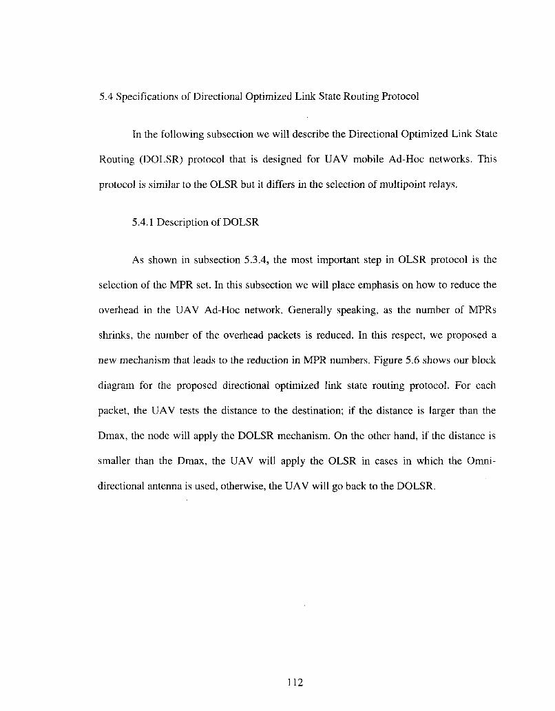
5.4 Specifications of Directional Optimized Link State Routing Protocol
In the following subsection we will describe the Directional Optimized Link State
Routing (DOLSR) protocol that is designed for UAV mobile Ad-Hoc networks. This
protocol is similar to the OLSR but it differs in the selection of multipoint relays.
5.4.1 Description of DOLSR
As shown in subsection 5.3.4, the most important step in OLSR protocol is the
selection of the MPR set. In this subsection we will place emphasis on how to reduce the
overhead in the UAV Ad-Hoc network. Generally speaking, as the number of MPRs
shrinks, the number of the overhead packets is reduced. In this respect, we proposed a
new mechanism that leads to the reduction in MPR numbers. Figure 5.6 shows our block
diagram for the proposed directional optimized link state routing protocol. For each
packet, the UAV tests the distance to the destination; if the distance is larger than the
Dmax, the node will apply the DOLSR mechanism. On the other hand, if the distance is
smaller than the Dmax, the UAV will apply the OLSR in cases in which the Omni
directional antenna is used, otherwise, the UAV will go back to the DOLSR.
112

UAV (S) has data to UAV (D)
Yes No
Route norma
1
using OLSR *~~
'
Yes
StoD (D<Dmax/2)
V
(Ant==
No
"*̂ -
i '
Route using DOLSR
i'
END Figure 5.6: DOLSR Routing Protocol Block Diagram
5.4.2 Neighbor Discovery
To discover the neighbors in the Ad-Hoc network using directional optimized link
state routing protocol, Hello messages will be broadcasted periodically to all nodes as in
OLSR. These messages are only broadcasted one hop away and are not relayed to any
further nodes. Through this procedure, each node is capable of recognizing all its
neighbor nodes including those one-hop and two-hops away. We assumed that the two-
hop nodes are located within the range of the directional antenna. Any node located far
away will not be counted as a two-hop node.
113

5.4.3 Selection of Multipoint Relays in DOLSR
As an example, we will consider the UAV Ad-Hoc topology that is shown in
figure 5.7. We present a simple seven node scenario to illustrate our mechanism. In
OLSR MPR selection mechanism, a UAV marked as A will select C and D as its MPRs.
These UAVs cover all the un-reachable two-hop neighbors. Node F knows that it can
reach A via C and node F also knows that it can reach A via D. On the other side, node E
can reach A either through node C or node D. In DOLSR MPR selection mechanism, the
idea is to benefit from the use of the directional antenna and also from the global profile
created as a result of cross-layering technique. Node A will build its routing table based
on the OLSR selection as follows: A-C-F, A-G-E, A-C-B, A-D-G, A-D-E, A-D-B. Based
on these results, node A has two routes to nodes E and B. Our scheme will calculate the
distance between node A and nodes E and B; the longest distance will be considered as
MPR. Table 5.5 shows the selection of MPRs for both mechanisms, where node E is
selected as A's MPR in DOLSR mechanism while nodes C and D are selected in OLSR.
Table 5.5
MPR Selection in DOLSR and OLSR Mechanisms
Node A F
2-Hop Neighbors E , F , G A , B , D
MPR(s) in OLSR C,D C,G
MPR(s) in DOLSR E B
114

Figure 5.7: Ad-Hoc Topology, Illustration of Multipoint Relays in DOLSR and OLSR
5.4.4 Route Maintenance
Due to the mobility of the UAVs, route links in Ad-Hoc networks will be broken
frequently. Each UAV implements a DOLSR sending out a Hello message to maintain
local connectivity with other UAVs. Failure to receive a Hello message from other
UAVs is considered as an indication that the link to the UAV is broken. A link failure
notification message is then forwarded back until it reaches the source node. Once the
error message reaches the source node, the source node should respond by switching back
to the normal OLSR selection technique.
115

5.5 Performance Evaluation
5.5.1 Simulation Environment
To demonstrate the performance of the DOLSR protocol presented above, we
compared our scheme to the original OLSR protocol, AODV and DSR protocols. For our
simulation, which is different from others [99], we have used an OPNET 14.5, a discrete
event network simulator that includes a rich set of detailed models for Ad-Hoc network.
25 UAVs are placed as shown in figure 5.8 in a 2000 X 2000 m area and form a mobile
Ad-Hoc network. Both AMAC_UAV that is presented in chapter 4 and MAC protocols
operate at data rate of 11Mbps. The power transmit level of lmw was used for all
scenarios. The simulation period is 10 minutes and the UAVs are moving in the
simulation area according to a random waypoint model [98] with a zero pause time and a
constant speed of 40 m/sec. The packet size is set to 1024 bits and the distribution is
exponential. All UAVs in the network are configured to run OLSR protocol during the
first scenario and DOLSR protocol during the second one. We summarized the
parameters used in all scenarios in table 5.6.
Other scenarios were conducted to evaluate the performance of our scheme and
compare it with various mobile Ad-Hoc network routing protocols. We compared our
scheme to the AODV and DSR protocols. The AODV and DSR simulation parameters
used in the comparison are shown in tables 5.7 and 5.8 respectively. Moreover, we added
the original OLSR protocol to the comparison with the parameters shown in table 5.9.
116

Figure 5.8: Network Topology for 25 UAVs Used for Simulation
Table 5.6
Simulation Parameters for the 25 UAVs Ad-Hoc Networks
Parameters # of Nodes Mobility Simulation Time Data rate Area (m x m) Buffer size Packet reception power threshold Transmit power packet size Radio propagation model
Value 25
Random 10 minutes
11Mbps 2000m X 2000m
256000 bits -95 dBm
1 mw 1024 bits
DSSS
117

Table 5.7
Simulation Parameters Used for the AODV Protocol
Parameters Hello interval Allowed hello loss Packet queue size (packets) Active route timeout Route error rate limit (packets/sec)
Value Uniform( 1,1.1) ( seconds)
2 infinity
35 (seconds) 10
Table 5.8
Simulation Parameters Used for the DSR Protocol
Parameters Route expiry timer Max. buffer size (packets) Send buffer expiry timer Max. request period Broadcast jitter Initial request period
Value 300 (seconds)
infinity 30 (seconds) 10 (seconds)
Uniform(0,0.01 )(seconds) 0.5 (seconds)
Table 5.9
Simulation Parameters Used for the OLSR Protocol
Parameters Hello interval TC interval Topology hold time Neighbor hold time Duplicate message hold time Address mode
Value 2 second 5 second 15 second 6 second 30 second
IPv4
118

5.5.2 Performance Comparison between OLSR and DOLSR
We have conducted several scenarios and analyzed the results of simulation
obtained by the use of OLSR and DOLSR routing protocols for the average number of
MPRs selected by the network, total number of TC messages sent and forwarded by the
MPRs, total number of Hello messages sent and finally we make a comparison between
the two protocols in terms of End-to-End delay.
Figure 5.9 compares the two protocols in terms of the number of MPRs selected
by the network. As shown in the figure, our scheme gave better results than the original
OLSR. 14 MPRs are selected during the use of the OLSR while 10 MPRs are selected
during the use of DOLSR, this result agrees with what we introduce in section 5.4. After
200 seconds, when the nodes have selected their MPR set, the number of MPRs becomes
stable and converges to 14 and 10 nodes.
Figure 5.10 shows the number of TC messages forwarded during the simulation
time. Since all nodes are mobile, TC messages are used to propagate the changes in the
network topology. The number of the TC messages in the original OLSR is higher than
200 during the first 100 seconds, while in DOLSR the number is less than 160. This is
due to the reduction of the MPR set. The same result can be seen in Figure 5.11 in which
the DOLSR reduced the total number of the generated TC messages.
Figure 5.12 shows the performance comparison results for End-to-End delay
between the DOLSR protocol using directiorial antenna and the OLSR protocol using
Omni-directional antenna. Generally speaking, there are three factors affecting End-to-
End delay of a packet: time to discover the route, buffering waiting time and the number
119

of hops for each path. Since the number of the MPR set is reduced while using DOLSR,
clearly the time should also decrease.
The figure shows that DOLSR has less End-to-End delay than OLSR. The End-
to-End delay for both protocols is high at the beginning of the simulation time. This
reflects the fact that the size of the control traffic is high before the selection of the MPR
set. After each node selected its MPR set, the number of nodes used for flooding the
control messages will be decreased and restricted only for the MPR set and thus the time
will also be reduced.
Figure 5.13 shows the number of Hello messages used by DOLSR and OLSR
protocols. Both protocols deliver the same number of Hello messages over the simulation
time and thus the results show that they have the same trend. At the beginning of the
simulation time, the number of Hello messages is quite high for both protocols. These
messages are generally propagated by all nodes so that each node can discover all its two-
hop nodes. After nodes learn all neighbors, they select the MPR set and the number starts
to decline.
5.5.3 Performance Comparison between OLSR, DOLSR, AODV and DSR
The implementation of OLSR, DOLSR, AODV and DSR in this simulation is
mainly to evaluate End-to-End delay and traffic received (packets/ sec). We chose these
two parameters for our simulation in order to study the efficiency of our scheme in
reducing the time taken to send the packets from source to destination.
In general, UAV Ad-Hoc networks have characteristics in which the network
topology changes very rapidly. If nodes are within the communication range of each
120

other, messages will be exchanged between the senders and the receivers, otherwise
messages should be sent through intermediate node. The major challenge in mobile Ad-
Hoc networks is how to route the packets with frequent node movement. To see the
effects of the routing protocol on the performance of the UAV Ad-Hoc networks, we
selected two reactive protocols, AODV and DSR, and one proactive protocol OLSR.
Figure 5.14 and figure 5.15 show the total delay in the network. They are plotted
on different scales to make the difference between the four protocols visible. The total
delay is represented by the End-to-End delay. The End-to-End delay represents the time
interval that is calculated from the instant a packet is generated by the source node, to the
instant that the packet is received by the destination node. These figures compare the
End-to-End delay between the DOLSR protocol using directional antenna and the OLSR,
AODV, and DSR protocols using Omni-directional antenna. The total delay using Omni
directional antenna is higher than that of using directional antenna. This behavior may be
explained as follows: The range of the UAVs is extended as a result of using directional
antenna, and thus the number of MPRs is reduced due to the use of the DOLSR.
Both figures also show that DOLSR and OLSR provide smaller End-to-End delay
than AODV and DSR which is less than 0.005 seconds. Moreover, the End-to-End delay
for the AODV and DSR start at an average of 0.25 second and then fall to 0.05 seconds.
The difference in time can be related to the fact that AODV and DSR are reactive
protocols and construct their route on demand while the OLSR and DOLSR are proactive
protocols in which the table is available and has the destination addresses. For all
protocols, the graph starts after one hundred seconds because we programmed the
OPNET to deliver a packet after other modules register themselves.
121

Figure 5.16 compares the traffic received using the OLSR, DOLSR, AODV and
DSR protocols. It can be seen that DOLSR received more than 20 pkt /s over 10 minutes
simulation time, while AODV and DSR received less than 17 packets /s over the same
time. The reason is that AODV and DSR protocols tend to flood the network with heavy
control traffic which increases the End-to-End delay, while DOLSR minimizes the
control messages by multipoint relays which reduces the End-to-End delay.
20
18
16
14
12
10
'OLSR •DOLSR
gurnet*
100 200 300 400 Simulation Time (sec)
500 600
Figure 5.9: Comparison between OLSR and DOLSR Protocols for the Average Number of MPRs Selected by the Network
122

200 300 400 Simulation Time (sec)
600
Figure 5.10: Comparison between OLSR and DOLSR Protocols for the Total Number of TC Messages Forwarded by the MPRs
25
20
"c
on £> 15 05 t i l
£ 10
« ^ s M $m £&<
1
1
1
— — O L S R
•"««•>-DOLSR
s £ ^ lags $31 858$ ^ — ^«S ffi&S tt g§^ &# PS PSSTO ^ m 3P » 80 sSP* ^ ^ ^ *
1 1 1 1
100 200 300 400 Simulation Time (sec)
500 600
Figure 5.11: Comparison between OLSR and DOLSR Protocols for the Total Number of TC Messages Sent by the MPRs
123

0.025
0.02 -
0.015 -
6 0.01 -
0.005
I \
1 V _
®» sm mt sag ^ m am mt «s TO m
— OLSR - - - D O L S R
- — - -
100 200 300 400 Simulation Time (sec)
500 600
Figure 5.12: Comparison between OLSR and DOLSR Protocols for the End-To-End Delay
100
90
80
£ 70 h CO
g, 60 cts CO CO
J 50 -Q
1: 40
£ 30
20
10
: : : ;
K G
— OLSR — - DOLSR
i i i i i
100 200 300 400 Simulation Time (sec)
500 600
Figure 5.13: Comparison between OLSR and DOLSR Protocols for the Total Hello Message Sent
124

0.25
0 .2 -
JT 0 .15-a* Q 73
0.1
C LU
0.05
^ T 1 1 1
„
J
~"~
U L C J K
- - - D O L S R
AODV
" " ' • " D S R
-
100 200 300 400 Simulation Time (sec)
500 600
Figure 5.14: Comparison between OLSR, DOLSR, AODV and DSR Protocols for End-To-End Delay
0.06
0.05
5J 0.04 -
0.03
0.02
0.01
1
'
i :
1 • w . ! M
"
1
/ *
" • " -DOLSR AODV
- • ™ D S R
8S5 5B8S ™ s® ga " i
100 200 300 400 Simulation Time (sec)
500 600
Figure 5.15: Comparison between OLSR, DOLSR, AODV and DSR Protocols for End-To-End Delay (different scale for Y axis)
125

S 20
a.
200 300 400 Simulation Time (sec)
600
Figure 5.16: Comparison between OLSR, DOLSR, AODV and DSR Protocols for Traffic Received (packets/ sec)
5.6 Summary
In this chapter, a novel Directional Optimized Link State Routing (DOLSR)
protocol is proposed for UAV mobile Ad-Hoc networks. Our protocol is capable of
reducing the number of the multipoint relays in the network. As a result, the End-to-End
delay is reduced and the overall throughput is increased. Performance evaluation and
comparison between OLSR and AODV were studied using OPNET Modeler 14.5. The
simulation results show that OLSR achieves better performance than AODV in terms of
End-to-End delay. Another comparison was conducted between OLSR and DOLSR using
the same simulator. The simulation results show that DOLSR achieves better
performance than OLSR and AODV in terms of End-to-End delay. It can be concluded
that as the number of MPRs shrinks, the number of the overhead packets is reduced and
thus the overall performance is enhanced.
126

CHAPTER VI
CONCLUSION AND FUTURE WORK
6.1 Conclusion
Recently, UAV mobile Ad-Hoc networks have become one of the popular types
of wireless networks that are formed by a swarm of UAVs. Each UAV in such network
has the capability to communicate with its neighbors and non-neighbors through a
wireless medium without using any existing network infrastructure. The UAVs in these
networks are designed in such a way that they act as an end system and a router for other
aircrafts. Such networks are expected to play an important role in various areas especially
in delay critical applications.
Variation of wireless links as a result of using UAVs that are equipped with the
directional antenna may create several problems for network protocols that implement the
framework of layered architectures. In that respect, to integrate the directional antenna
successfully into UAV Ad-Hoc networks and to realize its benefits within the MAC and
network layers, Cross-layer technique was implemented in this dissertation so that the
first three layers can inter-communicate the useful information and dynamically adjust
the transmission parameters according to these variations.
Cross-layer technique was presented in Chapter 3. First, we gave a brief
description of the two most important models used in wireless network: the open system
interconnection (OSI) model and the TCP/IP model. Then we discussed some
characteristics that a UAV network posses and how it differs from other networks, such
as the effect of aircraft attitude on the MANET performance and the effect of the aircraft
127

fuselage on the antenna system. These characteristics make the models mentioned above
inefficient and not effective in such networks. At the end of this chapter, we presented
two architectures that are published for the Ad-Hoc network; those are architectures
based on local profiles and architectures based on global and local profiles. Last, we have
presented our new architecture that is called Target-Source Based Architecture. This
architecture has only incorporated the following layers: physical layer, data link layer and
network layer. Both data link and network layers were measured by throughput and delay,
while physical layer was measured by Bit-Error-Rate (BER). Layer protocols were
adjusted to satisfy our goal and adapt UAV constraints.
In Chapter 4, a novel Adaptive Medium Access Control protocol was proposed
for UAV mobile Ad-Hoc networks (AMACJJAV). The first part of this chapter
reviewed both the MAC layer and the physical layer and provided detailed information
about IEEE 802.11 standard and the concept of smart antenna. In the second part, we
focused on the implementation of the UAV in OPNET Modeler 14.5. We developed a
model for each UAV with two directional and two Omni-directional antennas. This
model was able to send and receive traffic using both types of antenna. Meanwhile, we
have constructed our directional antenna pattern using antenna pattern editor provided by
OPNET. A short description of OPNET Modeler 14.5 was also given. Channel model,
UAV mobility model and our new MAC scheme (AMAC_UAV) were also introduced in
full detail. We analyzed the performance of our scheme and the data collected from the
simulation scenarios. We observed that using directional antenna in UAV Ad-Hoc
network provided better performance than Omni-directional antenna in terms of End-to-
End delay.
128

In Chapter 5, Directional Optimized Link State Routing (DOLSR) protocol was
proposed for UAV mobile Ad-Hoc networks. Our protocol was capable of reducing the
number of the multipoint relays in the network. As a result, the end-to-end delay was
reduced and the overall throughput was increased. Performance evaluation and
comparison between OLSR and AODV protocols were studied using OPNET Modeler
14.5. The simulation results showed that OLSR protocol achieved better performance
than AODV protocol in terms of end-to-end delay. Another comparison was conducted
between OLSR and DOLSR protocols using the same simulator. The simulation results
showed that DOLSR protocol achieved better performance than OLSR and AODV
protocols in terms of end-to-end delay. In this chapter, we concluded that as the number
of MPRs shrinks, the number of the overhead packets is reduced and thus the overall
performance is enhanced.
6.2 Future Work
The ideas presented in this dissertation can be expanded to enable our system to
work similar to those systems that are used in commercial aircrafts. For example, Traffic
alert and Collision Avoidance System (TCAS is one of the systems that is used to
monitor the space around aircrafts; it continually sends a navigation message that
describes the position of the aircraft. This message is then processed and an alarm is
issued to indicate if there is another aircraft passing too closely to the owner of this
message. To do that, application layer should be included in our architecture which is
presented in Chapter 3. Also, a new mechanism should be developed to interface the
129

communication system with the navigation system so that the aircraft navigation system
can control the movement of the aircraft based on the data coming from our system.
130

BIBLIOGRAPHY
[1] Dongwon Jung and Panagiotis Tsiotras,"Inertial attitude and position reference system development for a small UAV," in 26th AIAA Aeroacoustics Conference, May 2005.
[2] Kai Chen, Samarath. H. Shan, and Klara Nahrstedt, "Cross-Layer design for data accessibility in mobile Ad-hoc networks," Wireless Personal Communications, Vol. 21, No. 1, pages: 49-76, April 2002.
[3] Hetal Jasani, and Kang Yen, "Performance improvement using directional antennas in Ad-Hoc networks," IJCSNS International Journal of Computer Science and Network Security, vol. 6, no. 6, pages: 180-188, 2006.
[4] Ram Ramanathan, Jason Redi, Cesar Santivanez, David Wiggins, and Stephen Polit, "Ad-Hoc networking with directional antennas: A complete system solution," IEEE JOURNAL, vol. 23, no. 3, pages: 496-506, 2005.
[5] Jianfeng Wang, Yuguang Fang, and Dapeng Wu, "Syn-dmac: A directional MAC protocol for Ad-Hoc networks with synchronization," IEEE JOURNAL, vol. 4, no. 3, pages: 2258-2263, 2006.
[6] Mineo Takai, Jay Martin, Aifeng Ren, and Rajive Bagrodia, "Directional virtual carrier sensing for directional antennas in mobile Ad-Hoc networks," Proc. of the ACM MobiHoc'02, Lausanne, Switzerland, June 9-11, pages: 183-193, 2002.
[7] Young-Bae Ko, Vinaychandra Shankarkumar, and Nitin H. Vaidya, "Medium access control protocols using directional antennas in Ad-Hoc networks," in INFOCOM 2000, Nineteenth Annual Joint Conference of the IEEE Computer and Communications Societies, Proceedings IEEE, 2000.
[8] Timothy X Brown, Brian Argrow , Cory Dixon, Sheetalkumar Doshi, Roshan-George Thekkekunnel, Daniel Henkel, "Ad-hoc UAV Ground Network (AUGNet)," AIAA 3rd "Unmanned Unlimited" Technical Conference, Chicago, IL, 20-23 Sep 2004.
[9] Timothy X Brown, Sheetalkumar Doshi, Sushant Jadhav, and Jesse Himmelstei, "Test Bed for a Wireless Network on Small UAVs," AIAA 3rd Unmanned Unlimited Technical Conference, Chicago, IL, 20-23 Sep 2004.
[10] Chen-Mou Cheng, Pai-Hsiang Hsiao, H. T. Kung, Dario Vlah, "Performance Measurement of 802.11a Wireless Links from UAV to Ground Nodes with Various Antenna Orientations," Proc. 15th International Conference on Computer Communications and Networks (ICCCN 2006), October 9-10, 2006.
131

[11] Ulas C. Kozat, Iordanis Koutsopoulos, and Leandros, "A framework for cross-layer design of energy-efficient communication with QoS provisioning in multi-hop wireless networks," In Proceedings Joint Conf. of the IEEE Comp. and Comm. Societies (INFOCOM), vol. 2, pages: 1446-1456, 7-11 March 2004.
[12] Rahul Mahajan, "Cross-layer Optimization: System Design and Simulation Methodologies," M.S. Thesis, Virginia Polytechnic Institute, Nov 2003.
[13] Carneiro, G. Ruela, and J. Ricardo, "Cross-layer design in 4G wireless terminals," IEEE Wireless Communications, Volume: 11, Issue: 2, pages: 7- 13, Apr 2004.
[14] Eric Setton, Taesang Yoo, Xiaoqing Zhu, Andrea Goldsmith, and Bernd Girod, "Cross-layer design of Ad-Hoc networks for real-time video streaming," IEEE Wireless Commun. Mag., vol. 12, no. 4, pp. 59-65, Aug. 2005.
[15] Andrea J. Goldsmith, and Stephen B. Wicker, "Design Challenges for Energy-Constrained Ad-Hoc Wireless Networks," IEEE Wireless Communications, Volume: 9, Issue: 4 pages: 8-27, August 2002.
[16] Cruz R.L. and Santhanam A.V., "Optimal link scheduling and power control in CDMA multihop wireless networks," In Globecom'02, IEEE, Volume: 1, pages: 52- 56, Nov. 2002,
[17] Merz R., Widmer J., Le BoudecJ. Y., and Radunovic B., "A joint PHY/MAC architecture for low-radiated power TH-UWB wireless Ad-hoc networks," Wireless Communications and Mobile Computing Journal, Volume: 5, pages 567-580, June 2005.
[18] S. Toumpis and Andrea J. Goldsmith, "Capacity regions for wireless Ad-Hoc networks," IEEE international conference on communications, Volume: 5 , pages 3168-3173,July 2003.
[19] M. Neely, E. Modiano, and C. Rohrs, " Dynamic power allocation and routing for time varying wireless networks," IEEE INFOCOM , Volume: 1, pages 745-755, January 2005.
[20] D. Goldenberg, J. Lin, A. S. Morse, B. E. Rosen, and Y. R. yang, "Towards Mobility as a Network Control Primitive," In Proceedings of the 5th ACM international symposium on Mobile Ad-Hoc networking and computing, Japan: ACM, Pages: 163 -174, 2004.
[21] Srinivasan S., and Latchman H., "Airborne Traffic Surveillance Systems - Video Surveillance of Highway Traffic," In Proceedings of the ACM 2nd international workshop on Video surveillance & sensor networks. New York, NY, USA, Pages: 131 -135, 2004
132

[22] Zhuochuan Huang and Chien-Chung Shen, "A comparison study of omni-directional and directional MAC protocols for Ad-Hoc networks," In Proc. of IEEE Globecom'02, vol 1, pages 57-61, 2002.
[23] R. Ramanathan, "On the performance of Ad-Hoc networks with beamforming antennas," In Proceedings of the 2nd ACM international symposium on Mobile Ad-Hoc networking & computing, California, pages 95-105, October 4-5, 2001.
[24] S. Horisawa , S. Bandyopadhyay, K. Hausike and S. Tawara, "An adaptive MAC and directional routing protocol for Ad-hoc wireless networks using ESPAR antenna," In Proceedings of the 2nd ACM international symposium on Mobile Ad-Hoc networking & computing, Pages: 243 - 246 , Oct 2001.
[25] Ping-Cheng Yeh, Wayne E. Stark and Salam A. Zummo, "Performance Analysis of Wireless Networks with Directional Antennas," IEEE transactions on vehicular technology, vol. 57, Pages: 3187-3199, Nov 2008.
[26] Dixon C, Henkel D., Frew E.W., and Brown T.X., "Phase transitions for controlled mobility in wireless Ad-Hoc networks," In AIAA Guidance, Navigation, and Control Conference and Exhibit, Keystone, Colorado ,21 - 24 August 2006.
[27] R.R. Choudhury, X. Yang, R. Ramanathan, and N. Vaidya, "Using directional antennas for medium access control in Ad-Hoc networks," In Proceedings of the 8th annual international conference on Mobile computing and networking, Pages: 59 - 70, Sep. 2002.
[28] J.C. Mundarath, P. Ramanathan, and B.D. Van Veen, "NULLHOC: a MAC protocol for adaptive antenna array based wireless Ad-Hoc networks in multipath environments," IEEE Global Telecommunications Conference, Dallas TX, vol. 6, Pages: 2765-2769, 2004.
[29] R.R. Choudhury, X. Yang, R. Ramanathan, and N.H. Vaidya, "On designing MAC protocols for wireless networks using directional antennas," IEEE Transactions on Mobile Computing, vol. 5, Issue 5, pages: 477-491, May 2006.
[30] A. Singh, P. Ramanathan, and B.V. Veen, "Spatial reuse through adaptive interference cancellation in multi-antenna wireless networks,"Global Telecommunications Conference, Vol. 5, Nov. 2005.
[31] M. Takata, M. Bandai, and T. Watanabe, "Performance analysis of a directional MAC protocol for location information staleness in MANETs," in IPSJ journal, volume 46, pages: 2623-2632, November 2005.
[32] R. Preston, J. Doane, and D. Kiwior, "Using real world data to create OPNET models," in The MITRE Corporation Bedford, MA 01730, Aug. 3, 2005.
133

[33] G. Mao, S. Drake, and B. D. O. Anderson, "Design of an extended kalman filter for UAV localization," IEEE JOURNAL, pp. 224-229, 2007.
[34] A. Nasipuri, J. Mandava, "On-Demand Routing Using Directional Antennas in Mobile Ad Hoc Networks," in Proceedings of the IEEE International Conference on Computer Communication and Networks (ICCCN2000), October, 2000.
[35] Amit Kumar Sana, "Energy Saving and Parition Bridging using Directional Antennas in mobile ad hoc networks," Master thesis, May, 2003.
[36] R. Choudhury, and N. Vaidya, "Impact of Directional Antennas on Ad Hoc Routing," 8th Conference on Personal and Wireless Communication (PWC) September 2003.
[37] J. A. Miller, P. D. Minear, and A. F. Niessner, "Intelligent unmanned air vehicle flight systems," in AIAA InfoTech, Aerospace Conference, 2005.
[38] R. J. Bamberger, D. H. Scheidt, R. C. Hawthorne, O. Farrag, and M. J. White, "Wireless network communications architecture for swarms of small UAVs," in AIAA 3rd Unmanned Unlimited Technical Conference, Workshop and Exhibit, 2004.
[39] R. Preston, J. Doane, and D. Kiwior, "Using real world data to create OPNET models," in The MITRE Corporation Bedford, MA 01730, 2005.
[40] I. Crdei and S. Kazi, "MAC layer QoS support for wireless networks of unmanned air vehicles," in Proceedings of the Proceedings of the 37th Annual Hawaii International Conference on System Sciences, 2004.
[41] Gentian Jakllari , Wenjie Luo and Srikanth V. Krishnamurthy, "An Integrated Neighbor Discovery and MAC Protocol for Ad Hoc Networks Using Directional Antennas," IEEE JOURNAL, Volume: 6, Issue: 3, pages: 1114-1124, March 2007.
[42] Shafiullah Khan, Kok Keong Loo and Zia Ud Din, "Cross Layer Design for Routing and Security in Multi-hop Wireless Networks," Journal of Information Assurance and Security, June 10, 2009.
[43] Vineet Srivastava and Mehul Motani, "Cross-layer design: A survey and the road ahead," IEEE Communications Magazine, Vol. 43, No. 12, pp. 112-119, December 2005.
[44] Macro Conti, Gaia Maselli, Giovanni Turi and Silvia Giordano, "Cross- layering in mobile Ad hoc network design," IEEE Computer Society, pp. 48-51, February 2004.
[45] Rolf Winter, Jochen Schiller, Freie Berlin, Navid Nikaein, and Christian Bonnet, "Cross talk: cross-layer decision support based on global knowledge," IEEE Communications, Vol. 44, No. 1, January 2006.
134

[46] Vikas Kawadia and P. R. Kumar, "A cautionary perspective on cross-layer design," IEEE Wireless Communications, Vol. 12, pp. 3-11, February 2005.
[47] Evan D. Andersen, "A surveillance system to create and distribute geo-referenced mosaics from SUAV video," Master thesis, august 2008.
[48] Brandon T. Jones, "An evaluation of a low-cost UAV approach to noxious weed mapping," Master thesis, September 2007.
[49] Steven R. Hansen, "Applications of search theory to coordinated searching by unmanned aerial vehicles," Master thesis, April 2007.
[50] Kevin M. Morris, "Performance analysis of a cooperative search algorithm for multiple unmanned aerial vehicles under limited communication conditions," Master thesis, March 2006.
[51] Dan Hague, H. T. Kung, and Bruce Suter, "Field experimentation of cots-based UAV networks," Military Communications Conference, MILCOM 2006 IEEE, page(s): 1-7, Oct. 2006.
[52] A. Urpi, M. Bonuccelli, and S. Giordano, "Modeling Cooperation in Mobile Ad Hoc Networks: A Formal Description of Selfishness," Proc. WiOpt'03 Conf.: Modeling and Optimization in Mobile, Ad Hoc and Wireless Networks, March 2003.
[53] Rubin Izhak and Zhang Runhe, "Placement of UAVs as Communication Relays Aiding Mobile Ad Hoc Wireless Networks," Military Communications Conference IEEE, MILCOM 2007, Page(s):l - 7, Oct. 2007.
[54] Kuiper Erik and Simin Nadjm-Tehrani, "Mobility Models for UAV Group Reconnaissance Applications," 2nd International Conference on Wireless and Mobile Communications, Bucharest, Romania, 29-31 July 2006.
[55] Tim Tozer, David Grace, D. Thompson, and Baynham J., "UAVs and HAPs -Potential Convergence for Military Communications," Military Satellite Communications, IEE Colloquium, 2000.
[56] A. Nasipuri, S. Ye, J. You, and R. Hiromoto, "A MAC protocol for mobile Ad Hoc networks using directional antennas," In Proceedings of IEEE Wireless Communication and Networking Conference, Chicago, vol. 3, pp. 1214-1219, September 2000.
[57] Fahmy Nader and Todd Terence,"A selective CSMA protocol with cooperative nulling for Ad Hoc networks with smart antennas," Proceedings of IEEE Wireless Communications and Networking Conference (WCNC'04), March, 2004.
135

[58] Singh Harkirat and Singh Suresh, "Tone based MAC protocol for use with Adaptive Array Antennas," Proceedings of IEEE Wireless Communications and Networking Conference (WCNC'04), March, 2004.
[59] L. Bao, and J.J. Garcia-Luna-Aceves, "Transmission scheduling in Ad Hoc networks with directional antennas," In ACM/SIGMOBILE MobiCom 2002, 23-28 Sept. 2002.
[60] Thanasis Korakis, Gentian Jakllari and Leandros Tassiulas, " A MAC Protocol for Full Exploitation of Directional Antennas in Ad-Hoc Wireless Networks," In Proceedings of ACM MOBIHOC, 2003.
[61] Jun Yang, Jiandong Li, and Min Sheng, "MAC protocol for mobile Ad Hoc network with smart antennas," Electronics Letters, vol. 39, no. 6, pp. 555-557, March 2003.
[62] R.R. Choudhury and N.H. Vaidya, "Deafness: A MAC Problem in Ad Hoc Networks when using Directional Antennas," in IEEE International Conference on Network Protocols (ICNP), pp. 283-292, Oct. 2004.
[63] Ramesh Palat, A. Annamalau, and J. Reed, "Cooperative relaying for Ad-Hoc ground networks using swarm UAVs," IEEE MILCOM, vol. 3, pp. 1588-1594, Oct 2005.
[64] S. M. Swanson,"Evalution of an OPNET model for Tactical Targeting Network Technology (TTNT) Airborne Network," MS Thesis, AFIT/GE/ENG/08-32, School of Engineering and Management, Air Force Institute of Technology, March 2008.
[65] Clifton M. Durham, "Evaluation of an OPNET model for Unmanned Aerial Vehicle Networks," MS Thesis, AFIT/GCO/ENG/09-04, School of Engineering and Management, Air Force Institute of Technology, March 2009.
[66] Chen-Mou Cheng, Pai-Hsiang Hsiao, H. T. Kung and Dario Vlah, "Maximizing Throughput of UAV-Relaying Networks with the Load-Carry-and-Deliver Paradigm," in IEEE Wireless Communications and Networking Conference (WCNC 2007), Hong Kong, Mar. 2007.
[67] Daniel Henkel and Timothy X. Brown,"Optimizing the use of relays for link establishment in wireless networks," In Proc. IEEE Wireless Communications and Networking Conference (WCNC), Hong Kong, 2007.
[68] Kevin M. Morris, Barry E. Mullins, Daniel J. Pack, George W. P. York, and Rusty O. Baldwin, "Impact of Limited Communications on a Cooperative Search Algorithm for Multiple UAVs," IEEE International Conference on Networking, Sensing and Control, 2006.
136

[69] Izhak Ruhin, Arash Behzad, Huei-Jiun Jn, Runhe Zhang, Xiaoloug Huang, Yicheu Liu, and Rima Khalaf, "Ad hoc wireless networks with mobile ackbones," IEEE PIMRC, vol. 1, pp. 566-573, 2004.
[70] P. Basu, J. Redi, and V. Shurbanov,"Coordinated flocking of UAVs for improved connectivity of mobile ground nodes," Proc. of the 2004 IEEE Military Communications Conference (MILCOM 2004), pages 1628-1634, 2004.
[71] B. Ramachandran and S. Shanmugavel,"A Power Conservative Cross 1400 - AOD Layer Design for Mobile Ad-Hoc Networks," Information Technology Journal 4(2), pp 125-131,2005.
[72] S. Shakkottai, T. S. Rappaport, and P. C. Karlsson,"Cross-layer design for wireless networks," IEEE Commun. Mag., vol. 41, no. 10, pp. 74-80, Oct. 2003.
[73] V. T. Raisinghani and S. Iyer,"Cross-layer design optimizations in wireless protocol stack," Comp. Commun., vol. 27, pp. 720-724, 2004.
[74] M. van der Schaar and S. Shankar N, "Cross-layer wireless multimedia transmission: challenges, principles, and new paradigms," IEEE Wireless Commun., vol. 12, no. 4, pp. 50-58, Aug. 2005.
[75] Mihaela van der Schaar and Deepak S. Turaga,"Cross-layer packetization and retransmission strategies for delay-sensitive wireless multimedia transmission," IEEE Trans. Multimedia, vol. 9, pp. 185-197, Jan. 2007.
[76] Tamer Nadeem, "Efficient cross layer designs for IEEE 802.11 wireless networks," Doctor of Philosophy, University of Maryland, 2006.
[77] Bozidar Radunovic,"A Cross-Layer Design of Wireless Ad-Hoc Networks," Doctor of Philosophy, Ecole Polytechnique Federale de Lausanne, Lausanne, June 12, 2005.
[78] Xiaoyan Hong, Kaixin Xu, and Mario Gerla,"Scalable routing protocols for mobile Ad-Hoc networks," IEEE NETWORK, vol. 16, no. 4, 2002.
[79] Samir R. Das, Robert Castaneda, and Jiangtao Yan, "Simulation Based Performance Evaluation of Mobile, Ad-Hoc Network Routing Protocols," ACM/Baltzer MONET J., Volume 5 , Issue 3, pp. 179-189, July 2000.
[80] Xiaoyan Hong, Mario Gerla, Yunjung Yi, Kaixin Xu and Taek Jin Kwon, "Scalable Ad Hoc Routing in Large, Dense Wireless Networks Using Clustering and Landmarks," Proc. IEEE ICC 2002, New York, NY, Apr. 2002.
137

[81] Cesar Santivanez, Ram Ramanathan, and Ioannis Stavrakakis, "Making Link-State Routing Scale for Ad-Hoc Networks," International Symposium on Mobile Ad-Hoc Networking & Computing, Proceedings of the 2nd ACM international symposium on Mobile Ad-Hoc networking & computing, Long Beach, CA, USA , 2001.
[82] Zygmunt J. Haas and Marc R. Pearlman, "The Performance of Query Control Schemes for the Zone Routing Protocol," IEEE/ACM Transactions on Networking (TON), vol. 9, no. 4, pp. 427-438, Aug. 2001.
[83] Guangyu Pei, Mario Gerla and Xiaoyan Hong , "LANMAR: Landmark Routing for Large Scale Wireless Ad Hoc Networks with Group Mobility," Proc. IEEE/ACM MobiHOC 2000, Boston, MA, pp. 11-18, Aug. 2000.
[84] Cheolgi Kim, Young-Bae Ko and Nitin H. Vaidya, "Link-State Routing Protocol for Multi-Channel Multi-Interface Wireless Networks," MILCOM, Nov. 2008.
[85] Andrew S.Tanenbaum, "Computer Networks," Fourth Edition, Prentice-Hall Inc., 2005.
[86] Amit Kumar Saha and David B. Johnson, "Routing improvement using directional antennas in mobile Ad-Hoc networks," In Proceeding of IEEE GLOBALCOM'04., 2004.
[87] Romit Roy Choudhury and Nitin H. Vaidya, "Performance of Ad-Hoc Routing Using Directional Antennas," Journal of Ad-Hoc Networks, November, 2004.
[88] Ying Ge, Thomas Kunz and Louise Lamont, "Quality of Service Routing in Ad-Hoc Networks Using OLSR," in Proceeding of the 36th Hawii International Conference on System Science, 2003.
[89] A. Huhtonen,"Comparing AODV and OLSR routing protocols," Seminar on Internetworking, Sjkulla, 26-27 April 2004.
[90] Philippe Jacquet, Anis Laouiti, Pascale Minet, and Laurent Viennot, "Performance of Multipoint relaying in Ad-Hoc mobile routing protocols," Proceedings of the 2nd International IFIP-TC6 Networking Conference on Networking Technologies, Services, and Protocols, pp.387-398, 2002.
[91] Anthony Bus son , Nathalie Mitton, and EricFleury, "Analysis of the Multi-Point Relay Selection in OLSR and Implications", In the 4th Mediterranean Ad-Hoc Networking Workshop, MED-HOC-NET 05, France, June 2005.
[92] P. Jacquet, P. Muhlethaler, A. Qayyum, A. Laouiti, L. Viennot, and T. Clauseen, "Optimized Link State Routing Protocol," draft-ietf-manet-olsr-0.6.txt, Internet Draft, Mobile Ad-Hoc Networking Working Group, March 2002.
[93] http://www.ietf.org/rfc/rfc3626.txt.
138

[94] Jacquet P., Laouiti A., Minet P., and Viennot L., "Performance analysis of OLSR multipoint relay flooding in two Ad-Hoc wireless network models," research Report-4260, INRIA, Sept. 2001.
[95] Charles E. Perkins,"Ad Hoc Networking" Addision Wesley, 2001.
[96] Tseng Y., Shen C, and Chen W., "Mobile IP and Ad-Hoc networks: An integration and implementation experience," Technical report, Department of Computer Science, and Information Engineering., National Chiao Tung Univ., Taiwan, 2003.
[97] David B. Johnson David A. Maltz, and Josh Broch, "DSR: The dynamic source routing protocol for multi-hop wireless Ad-Hoc networks," In Ad-Hoc Networking, pp. 139-172,2001.
[98] Himabindu Pucha, Saumitra M. Das, and Y. Charlie Hu, "The Performance Impact of Traffic Patterns on Routing Protocols in Mobile Ad-Hoc Networks," Journal Computer networks, vol. 51, pp. 3595-3616, August 2007.
[99] Erik Nordstrom, Per Gunningberg, Christian Rohner, and Oskar Wibling,"A Comprehensive Comparison of MANET Routing Protocols in Simulation, Emulation and the Real World," Uppsala University, pp. 1-12, 2006.
[100] ANSI/IEEE 802.11, "Wireless LAN Medium Access Control (MAC) and Physical Layer (PHY) Specifications," 2000.
[101] Guoyou He,"Destination-Sequenced Distance Vector (DSDV) Protocol," Technical report, Helsinki, University of Technology, Finland, 2002.
[102] C. Perkins, E. Belding-Royer, and S. Das,"Ad-Hoc On-demand Distance Vector (AODV) routing," http://www.ietf.org/rfc/rfc3561.txt, July 2003.
[103] Rajendra V. Boppana, and Anket Mathur,"Analysis of the Dynamic Source Routing Protocol for Ad Hoc Networks," IEEE Workshop on Next Generation Wireless Networks (WoNGeN), India, December 2005.
139