cross-linked polymer gel seals horizontal degas...
TRANSCRIPT

I
11th U.S.lNorth American Mine Ventilation Symposium 2006 - Mutmansky & Ramani (eds) © 2006 Taylor & Francis Group, London, ISBN 0-415-40148-8 I
Cross-linked polymer gel seals horizontal degas boreholes Igreater than 4,000 feet long
SJ. Kravits & G.M. DuBois Target Drilling Inc.
J.M. Reilly Pennsylvania Services Corporation
J. Kirley Concrete Construction Materials
ABSTRACT: Horizontal boreholes drilled from within the mine or from the surface have proven to be effective in recovering coal bed methane for degasification and commercialization. However, the inability to completely plug horizontal boreholes still producing methane gas prior to mine-through has caused potentially hazardous situations and significant coal production delays. To date, cement slurry has been used predominantly to plug horizontal degasification boreholes, usually with unsatisfactory results. The purpose of this paper is to describe the successful sealing of 16 horizontal long boreholes and their abandoned sidetracks totaling 25,960 m (85,148') by pumping 349,320 1(92,290 gal) ofmetal cross-linked polymer gel from the surface to underground horizontal wellheads through slick-line suspended in cased vertical boreholes installed to the horizontal wellheads. Since almost two times the volume ofgel was pumped compared to the actual volume ofboreholes including sidetracks, the gel effectively squeezed into the fracture system of the coal displacing gas and water. Lastly, with an affinity to attach itself to everything, except for itself, the gel adhered to the inner wall of the borehole providing an impenetrable skin preventing gas and water to migrate back into the borehole as evidenced by observations noted when mining into the boreholes.
1 INTRODUCTION proven ineffective filling the entire void of the borehole and the borehole sidetracks. The ineffectiveness
The Mine Safety and Health Administration (MSHA) ofcement slurry results from a) dilution ofthe cement bas determined that Coal Bed Methane (CBM) wells in the slurry caused by mixing with water in the boreare subject to the same mine operator ventilation plan hole, b) heat and friction generated during the mixing and mapping requirements that apply to methane gas and pumping of the cement slurry causing pressure wells McKinney (2005). A mine operator that uti build-up in the borehole before the entire borehole lizes degas boreholes has to describe what precautions and sidetracks have been filled with cement slurry, they will take prior to mine-through, usually indicat and c) inherent shrinkage of the cement when it cures ing water infusing or plugging the boreholes in their or sets Aul and Cervik (1979). Consequently, plugMSHA approved ventilation plan. More recently, this ging degasification boreholes with cement slurry that includes specifying how Surface-To-In-Seam CBM have not had adequate degasification time prior to or Coal Mine Methane (CMM) wells will be plugged mine-through, have resulted in ignitions at the face according to the mine operator's MSHA approved and coal production delays on development, and obviVentilation Plan. ously much more devastating, when intercepted by
If a mine operator is not permitted to water infuse the longwall face. Consequently, when degasification a horizontal degas borehole prior to mine-through boreholes, that have not had adequate degasification by their MSHA approved ventilation plan, cement time prior to mine-through, have been plugged with slurry has been used predominantly to plug the cement slurry, the result has sometimes been ignitions horizontal degasification borehole. However, pump at the face and coal production delays on development ing cement slurry in horizontal boreholes has often sections, and obviously much more devastating, when
455
i ! Ii I ,.

intercepted by the longwall face. Given the overall safety and productivity contributions of degasification boreholes to mining, a more full-proof plugging material or methodology was required.
2 GEL BACKGROUND
Target Drilling Inc. (TDI) has directionally drilled over 100 in-mine horizontal degas boreholes greater than 1,220 m (4,000 ft) and several Surface Directional Horizontal CBM Wells with horizontal laterals in the coalbed for Foundation Coal's (Foundation) Coal Gas Recovery, LP (CGR) at Foundation's Cumberland Coal Resources, LP and Emerald Coal Resources, LP coal mines. As an alternative to either water infusing or plugging these in-mine or surface directional horizontal boreholes with cement slurry prior to mine-through, CGR and TDI solicited the technical support and experience of Concrete Construction Materials (CCM) to develop an alternative to sealing or plugging these boreholes with cement slurry by using a gel. Generally, the gel would be designed to be highly viscous, similar to water, so that it could be pumped very long distances, and at a specifically designed timeframe, cure to a semi-solid state that could be maintained for greater than 6 months. The gel was designed as a relatively thin liquid with viscosity of 1000 cp at shear so the gel could be pumped distances greater than 3 km (10,000'). As the borehole fills with gel and becomes pressurized, the gel would squeeze into and infiltrate the natural fracture system of the coal forcing gas and water into the natural fractures of the coal. Finally, as the water soluble gel mix, cures or "gels" into a semisolid, insoluble gel at the designed "gel time," it would form a skin or filter cake on the inside wall ofthe borehole preventing migration of gas and water back into the borehole (Figure 1).
3 CHEMICAL DESCRIPTION OF THE GEL
CCM developed a man made, proprietary inorganic, metal cross-linked polymer gel consisting of: 1) 9799% water by weight, 2) 2-3% by weight liquid high molecular weight water-soluble, partially hydrated, poly acrylimide polymer product (PHPA) called VMA-007; 3) less than 1/2% by weight valiant chromium ion XLR-C, used to "cross-link" or complex the poly acrylimide material (VMA 007) to change the polymer from water soluble to insoluble and; 4) less than 1/4% by weight liquid accelerator and conditioner to control reaction rate (Activator-M).ln simple terms, the poly acrylimide, in excess of 2 million molecular lengths, is aHowed to hydrate with water creating a mixture similar to a bowl of noodles. Then at a specific time, based on the mix design, chromium III ions
456
--_._--- ---
Butt cleat
Figure I. Polymer gel forces gas and water into fracture system.
attach at bonding points in between the noodles creating extremely over cooked noodles. CCM hired an independent laboratory to develop specific concentrations of the individual components for the gel mix based on the desired times required for mixing, pumping, setting and maintaining its semi-solid state by conducting tests in their laboratory. .
Table 1 is an Information Document for the meta! cross-linked polymer gel mix structured as an MSD8 sheet, but it is NOT an actual MSDS sheet. Slight variations in mixing in the field make it difficult to develop a representative MSDS. Before the gel was used initially to seal degas boreholes, meetings were held between representatives from the local work force's safety department, mine management, MSHA DistriCt 2; an MSHA Toxologist, CCM, and TDI. The meetings resulted in concluding that the gel ingredients and mixed gel were not toxic or hazardous providing adequate training was conducted for safe handling, mixing and pumping of the gel ingredients and that the final gel mix - either as a viscous liquid or semi-solid would not be hazardous or jeopardize the safety and well being of the local workforce if they came in con~
tact with the gel. It is important to note, this product combination ofgel mix was developed specifically for this application and to overcome the deficiencies of . using a modified guar. The material is resistant to bac, . terial attack and stable to decay for long periods <rl," time. Other natural gel systems (guar and low cost ?Il:. field viscosity agents) consist of food type maten~~, which present bacteria issues and long-term stabIlIty"" problems.
4 LABORATORY AND SURFACE TRIAL GEL TESTS
Laboratory tests and trial field tests were conducted. prior to sealing or gelling the horizontal boreholes.!be " gel mix can be modified to fit different comb!natJOuJ' ' of gel time, temperature and required pumpmg au setting viscosity. The purpose of the laboratory tests
._--- -- .---'---
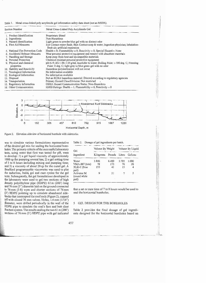
Table I. Metal cross-linked poly acrylimide gel information safety data sheet (not an MSDS).
Section Number Metal Cross-Linked Poly Acrylimide Gel
1. Product Identification Proprietary Blend 2. Ingredients Non-Hazardous 3. Hazard Identification Light green to powder blue gel with no distinct odor 4. First Aid Measures Eye Contact-water flush; Skin Contact-soap & water; Ingestion-physician; Inhalation-
fresh air; artificial respiration 5. National Fire Prevention Code Health = 0; Flammability = 0; Reactivity = 0; Special Hazard = None 6. Accidental Release Measures Wear personal protective equipment and remove with absorbent materials 7. Handling and Storage Keep away from heat and incompatible materials 8. Personal Protection Chemical resistant personal protective equipment 9. Pbysical and chemical pH:6-9; SG: 1.0(}-1.05 g/ml; Insoluble to water; Boiling Point: > 100deg. C; Freezing
properties Point: 0 deg. C; light gray to blue green gel with no odor . 10. Stability and Reactivity Hazardous polymerization will not occur 11. Toxological Information No information available 12. EcologicalInformation No information available ]3. Disposal Not an RCRA hazardous material. Discard according to regulatory agencies ~lj14. Transportation Primary Hazard ClasslDivision: Not restricted I
15. Regulatory Information OSHA Hazard Communication Status: Non-Hazardous J' 16. Other Communication Hl'vflS Ratings: Health = l; Flammability = 0; Reactivity = 0 ,I r..I
3
E 0 c: 0 -3 ~ QI -6ill
-9 o
I
J "Abandoned Roof Sidetracks -....... --. / \"-< J
.- / - '--.:... ~'-
152 305 457 610 762 915 1067 1220
Horizontal Depth, m ~
~ ;Figure 2. Elevation sideview of horizontal borehole with sidetracks. . l
was to simulate various formulations representative Table 2. Dosage of gel ingredients per batch.
of the desired gel mix for sealing the horizontal boreVolume By Weight Volwne By Liquid holes. The primary criteria ofthe successful laboratory Gel
tests, using water that first was tested for pH, were Ingredient Kilograms Pounds Liters Gallonsto develop: 1) a gelliqujd viscosity of approximately
lOOO cp for pumping several km; 2) a gel setting time Water 3.846 8.480 3.785 1.000
of 5 to 8 hours including mixing and pumping time; VMA-007 (tote) 78 173 76 20 and 3) a viscosity of about 20 cp for the cured gel. A XLR-C (blue 155 41 15 4 Bradford programmable viscometer was used to plot pail) the induction, build, gel and cure cycles for the gel Activator M 9 21 7 2 tests. Subsequently, the gel formulations developed in (round white the laboratory were used to gel two sections of high pail)
.density polyethylene pipe (HDPE) 61 m (200') long qnd 76 mm (3") diameter laid on the ground connected to 76 mm (3 ft) wyes and shorter sections of 76 mm that a set or cure time of 7 to 8 hours would be used to (3') HDPE pointing up to simulate abandoned side seal the horizontal boreholes. ',.tracks that intercepted the roof rock (Figure 2), capped off with closed 76 mm valves. Holes, 1.6mm (1/16") !llameter, were drilled periodically in the wall of the 5 GEL DESIGN FOR THE BOREHOLES HDPE pipe to simulate the coal's face and butt cleat fracture system. The results sealing the two 61 m (200') Table 2 provides the final dosage of gel ingredisections of 76 mm (3') HDPE pipe with gel indicated ents designed for the horizontal boreholes based on
457
II II
-----'-' ,
r .I t
"
~ I
the laboratory and HDPE trial gel tests with mixing gel batches with 3,7851 (1,000 gal) of water. Due to potential problems underground out of our control such as a mine fan going down, it wa's decided to mix 3,7851 (1,000 gal) batches at a time to minimize potential losses ifpumping had to be terminated prematurely. It was arbitrarily established to apply a volume Factor of Safety of2 for the volume ofgel mix to I) fill the boreholes, including sidetracks, 2) force gel into the fracture system of the coal displacing gas and water, and 3) develop a maximum gel pressure of 690 kPa (100 psi) at the horizontal wellhead to form a skin or filter cake on the inner borehole wall, which would prevent gas and water to flow back into the borehole. A very positive feature of the metal cross-link poly acrylimide gel mix was that the gel mix displays an affinity to attach or adhere to everything, except for adhering to itself. The gel pressures at the boreholes were not allowed to exceed 690 kPa (100 psi), the water tested capability of the wellhead control collar pipes. Trimming line or conduit would not be installed in the horizontal boreholes to transport the gel mix to the end of the horizontal boreholes because of the high viscosity of the liquid gel. It was very important that a sample of the water to be used to mix with the gel ingredients was tested for pH so that CCM could make final adjustments to the concentration of the gel ingredients if necessary.
6 GEL MIXING AND PUMPING PROCEDURES
After Target's staff reviewed MSDS for the individ7
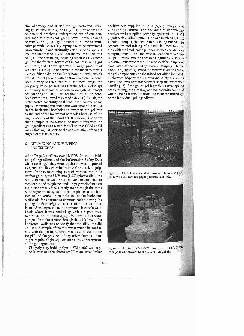
ual gel ingredients and the Information Safety Data Sheet for the gel, they were required to wear approved eye, hand and foot chemical personal protective equipment. Prior to mobilizing to each vertical vent hole surface gel site, the 31.75 n1m (1.251/) plastic slick-line was suspended down the vertical vent hole attached to steel cable and telephone cable. Apager telephone on the surface was wired directly (not through the mine wide pager phone system) to pager phones at the bottom of the vertical vent hole and at the horizontal wellheads for continuous communication during the gelling process (Figure 3). The slick-line was then installed underground to the horizontal borehole wellheads where it was hooked up with a bypass wye, two valves and a pressure gage. Water was then water pumped from the surface through the slick-line to the horizontal wellheads to verify that the slick-line did not leak. A sample of the mix water was to be used to mix with the gel ingredients was tested to determine for pH and the presence of any other chemicals that might require slight adjustment to the concentration of the gel ingredients.
The poly acrylimide polymer VMA-007 was supplied in totes and the chromium III metal cross-linker
458
additive was supplied in 18.91 (5 gal) blue pails or 2081 (55 gal) drums. The Activator M conditioner/ accelerator is supplied partially hydrated in l1.3sl (3 gal) white pails (Figure 4). As one batch of gel miX is being pumped, the next batch is being mixed. The preparation and mixing of a batch is timed to coincide with the batch being pumped so that a continuous pumping operation is achieved to keep the mixed liq- · uid gel flowing into the borehole (Figure 5). Viscosity measurements were taken and recorded for samples of' each batch of the mixed gel before pumping into the slick-line (Figure 6). Precautions were taken to handle the gel components and the mixed gel which included:, I) chemical impermeable gloves and safety glasses; 2) hands and arms were washed with soap and water after handling; 3) if the gel or gel ingredients were spilled onto clothing, the clothing was washed with soap arid water; and 4) it was prohibited to taste the mixed g<;J or the individual gel ingredients. . j'
I
Figure 3. Slick-line suspended down vent hole with paget, phone wire and devoted pager phone at vent hole. ' rt
Figure 4. A tote of VMA-007, blue pails of XLR-Cand
white pails ofActivator M at the vent hole gel site. '.'

Figure 5. Simultaneously pumping a batch of mixed gel (right) while circulating and mixing gel ingredients (left).
7 RESULTS OF SEALING BI, B2 AND B3 LONGWALL PANEL BOREHOLES WITH GEL
Sixteen (16) in-mine horizontal degasification boreholes drilled within 3 longwall panels were sealed using metal cross-linked poly acrylimide gel (Figures 7, 10 and 11). All of the boreholes were sealed by mixing and pumping the gel from the surface through plastic slick-line suspended down vertical vent holes and then traversed to the horizontal borehole wellheads following the mixing and pumping procedures described earlier. It was believed trimming pipe or conduit installed in the boreholes to convey the gel to the end of the boreholes would not be required because of the designed high viscosity of the liquid gel. It was pumped directly from the start of the 101.6 mm (41/) inner diameter wellhead plumbing the slick-line, gage, valves and bypass wy~ to the wellhead. Table 3 summarizes the results of sealing 16 in-mine horizontal coal degasification boreholes.
7.1 Results o/sealing Bl, B2 and B3 longwall panel boreholes with gel
The first two boreholes sealed with the metal crosslinked poly acrylimide gel were BI-5 and BI-6 (Figure 7). The longwall face mined into the end of both boreholes to find the ends filled with the gel including the sidetracks resulting in zero methane caused longwall production delays (Figure 8). Cure time for the gel was designed for 7 hours.
The actual volume ofgel pumped into B I-5 and B 16 of 22,712 I (6,000 gal) was 1.67 times the volume 1'1 of the two boreholes, including sidetracks. Pump pressure gradually increased as the boreholes' filled with gel as expected. Pumping was stopped when the horizontal wellhead pressure reached 483 kPa (70 psi). t,
I,
ItIHI
354mr- 814m (2670') ,~(1162')
I i' Vertical Vent Hole
81-3 Length 1232m (4040')
B1-4 Length 1253m (4110')
B I longwall panel boreholes sealed with metal cross-linked poly acrylimide gel.
459
'I,
*·'1
." figure 6. Taking a viscosity measurement of the mixed gel prior to pumping the mixed gel down the slick-line.
81-6 Length 637m (2090,)

Table 3. Results of sealing 16 horizontal boreholes with gel mixed and pumped from the surface. ~
Borehole Borehole length Gel volume Hor. wellhead Distance gel pumped length with sidetracks estimated ES. 2 Actual pumped pressure To end of borehoh: .
# Meters Feet Meters Feet Liters Gallons Liters Gallons kPa Psi Meters Feet
BI-6 741 2430 1134 3720 16214 4278 483 70 1240 4067 BI-5 637 2090 783 2567 11174 2952 22712 6000 483 70 1362 4467 BI-4 1253 4110 1744 5720 24898 6578 18925 5000 552 80 2337 7666 BI-3 1232 4040 1832 6010 26160 6912 22710 6000 1035 150 2309 7575 B2-6 1186 3890 1752 5745 25007 6607 24603 6500 414 60 3174 10412 B2-5 1049 3440 1601 5251 22856 6039 22710 6000 359 52 3063 10046 B2-4 1250 4100 1933 6340 27596 7291 20818 5500 276 40 2009 6591 B2-3 1244 4080 2125 6970 30339 8016 26495 7000 345 50 2013 6601 B2-2 1241 4070 1913 6274 27309 7215 23467 6200 483 70 1868 6127 82-1 1220 4000 1951 6400 27858 7360 15897 4200 400 58 1823 5978 83-6 1040 3410 1259 4131 17981 4751 20818 5500 414 60 2936 9631 83-5 991 3250 1140 3740 16279 4301 18925 5000 518 75 2897 9501 83-4 1265 4150 1725 5658 24628 6507 37850 10,000 290 42 1941 6366 83-3 1204 3950 1779 5836 25403 6711 30280 8000 242 35 1890 6199 83-2 1000 3280 1664 5457 23753 6276 18925 5000 483 70 2256 7400
.j 83-1 1293 4240 1625 5329 23196 6128 24186 6390 690 100 2549 8360, Tis. 17845 58530 25960 85148 370628 97920 349320 92290 N/A N/A 35667 116987
1" I'
I,. :f,II
1
Figure 8. 81-5 mined into by longwall face without incident. wall.
When the longwall intercepted the B 1-5 borehole it However, while pumping the first batch of gel in ihe was full o(cured gel. Minimum sloughing of the gel BI-3 borehole it began to thicken or set much fasteF
occurred after mine-through. Where the" gel sloughed than it was anticipated, increasing pumping pres~Uj from the top of the inner borehole wall, it was noted quickly to 552 kPa (80 psi). It was quickly deternuneI
1 that the gel had formed a thin layer or skin sticking to that more than the prescribed amount of Activator ~ 1, the inner wall. There was not any gas and water pro was used on the first batch. Additional water was adIJed
I duction from the gelled Bl-5 borehole when it was to thin the second batch that was already mixed aD;d • initially mined into by the longwall face. Sealing the waiting to be pumped because the first batch was tak·- ; B 1-5 and B 1-6 boreholes was considered a major suc ing longer to pump than it should. A total of 5 batcb~ cess because the boreholes did not cause any longwall were pumped in BI-3 or 1.7 times the volume 0
production delays. Consequently, it was decided to seal the BI-3 borehole including sidetracks when puJI19: . B 1-3 and 4 boreholes with the gel several months later. iug was stopped at a wellhead pressure of 1,035 kPa'
BI-3 and Bl-4 boreholes were sealed with the (150 psi). The last 3 batches of gel were mixed ~j(b. same gel formula used for BI-5 and BI-6 boreholes. the exact amount ofActivator M, as it was determWeD -.
460
Figure 9. Cross-linked polymer gel forms skin on boreholQ

82-3 Length 1244m (4080')
82-4 Length 12Som (4100'
B3-3 Length 1204m (3950')
83-4 Length 1265m (4150')
')-~~---1523m (4998')-----1
83-1 Length 1293m (4240,
B3-2length 1000m (32801
Figure 10. B210ngwall panel boreholes.
Figure 11. B3 longwall panel boreholes.
that tbe premixed containers of Activator M had t?O . much Activator M in them. B1-4 was then sealed wIth . 18,925 I (5,000 gal) of gel or 1.5 times the volume of the B 1-4 borehole obtaining a wellbead pressure of
·;552 kPa (80 psi). .;' The BI-3 borehole was full ofgel when the longwall lirst intercepted it. It remained full of gel for 199 m 0(649/) ofBI-3. However, BI-3 was then found to be
. void of gel for 485 m (1,591/). Fortunately, the borehole was producing little gas upon interception and Was easily diluted with existing face ventilation. To
-eliminate any potential hazard, the longwall crew foam packed the B 1-3 borehole every 6.1 m (20/). At a borebole depth of549 m (I ,800'), B1-3 was found to be full of gel. B1-3 and B1-5 were drilled to overlap as Illustrated in Figure 7 to provide continuous coverage from methane emissions on development. It is believed that gel pumped into B 1-5 and B1-6 migrated into the bottom end ofBI-3. It is also conceivable that the BI-3 gel did not fill the B1-3 borehole because the borehole caved and/or the first batch of gel with too much ActIvator M cured before it flowed to the bottom of tbe
, BI-3 borehole. BI-4 borebole was eitber completely filled with gel when it was mined into by the longwall face or if not entirely filled, a skin of gel was found to be adhered to the inner wall of the borehole preventing gas and water migration back into B1-4. It is also interesting to note that at times, slugs of gel were
,. being forced onto the longwall face as breaks in the .gob directly behind the shields were occurring, possibly indicating instantaneous increases in abutment loading out by the longwall face.
461
83-6 Length 1040m (3410')
7.2 Results o/sealing the B2 boreholes
The B2-5 and B2-6 longwall panel boreholes were sealed with gel pumping a total distance from the surface to the end of the boreholes over 3 km (10,000/). The actual gel volume pumped for these two boreholes was 1.99 times tbe volume of the boreholes including sidetracks. Overlap of boreboles B2-3, B2-4 and B2-1 probably had an impact on the gel volumes actually pumped totaling 1.66 times tbe calculated borehole volume, including sidetracks, in addition to leakage through the coal ribs near the wellheads at an average gel wellhead pressure of 366 kPa (53 psi). Likewi~e,
only 1.14 times the calculated borehole volume WIth sidetracks for B2-1 of gel was pumped even through experiencing gel leakage at the rib near the w~llhead
with a wellhead gel pressure of 400 kPa (58 pSI). The B2 longwall panel boreholes were either found to be full of gel or if not full, the gel bad formed a skin on the inner wall of the borehole. Consequently, the B2 longwall panel production was not interrupted due to gas delays caused by the B2 longwall boreholes.
7.3 Results o/sealing the B3 boreholes including mine through
More than two times tbe calculated volume of gel required was pumped into all oftlle B3 longwall panel boreholes, except for B3-2. A different form ofXLR-.C cross-linker was used on B3-4 whicb thinned the mix resulting in 3 times the volume of gel pumped into B3-4. CCM did not charge CGR for the additional

volume of gel pumped in B3-4 and resumed using the original form of liquid XLR-C for the remaining B3 boreholes. The B3-5 and B3-6 boreholes were mined into when with the continuous miner developed the longwall setup entries. The boreholes were found to be full ofgel. The B3 boreholes have not been mined into with the longwall face at the time this paper was written.
8 CONCLUSIONS
Sixteen in-mine horizontal boreholes and their abandoned sidetracks totaling 25,960m (85,148') were sealed by pumping 349,320 (92,290 gal) of metal cross-linked polymer gel from the surface to underground, through slick-line suspended in cased, vertical vent holes installed to· the horizontal wellheads and then plumbed to the wellheads. Due to the high viscosity of the liquid gel pumped, conduit was not required to be installed in the boreholes. Pumping almost two times the volume of gel pumped than the calculated volume of boreholes, including sidetracks, the gel effectively squeezed into the fracture system of the coal displacing gas and water. The gel attached itself to the inner wall of the borehole providing an impenetrable skin preventing gas and water to migrate back into the borehole, as evidenced by observations when mining into the boreholes.
Consistency problems in mixing and pumping the gel were overcome when more boreholes were sealed with the cross-linked poly acrylimide gel.
Improvements currently being implemented include constructing a more comprehensive gel system designed specifically for mixing and' pumping the gel ingredients and liquid gel mix. By more uniformly mixing the precise formulation of individual ingredients, the ability to pump the polymer gel through the
462
slick-line and into the boreholes to distances greater than 3 km (10,000') will be increased. Importantly, the polymer gel will be displaced into the horizontal degasification boreholes, either drilled from within the mine or from the surface, consistently with the designed pumping viscosity and cure viscosity to keep the borehole filled with cured gel when intercepted by mining. The development of this technology, which permits safe and productive mine-through degas of boreholes, helps ensure the continued growth in the utilization of degasification for overall safety and productivity benefits when mining gassy coalbeds.
ACKNOWLEDGEMENTS
The authors wish to acknowledge the continued support and perseverance of Pennsylvania Services Corporation's and Emerald Coal Resources, LP's senior management. Special thanks also go to Albert Giocondi, Emerald Coal Resources, LP's Degas Coordinator, whom without his daily commitment with his boots on the ground to work out the bugs to seal the boreholes with the cross-linked polymer gel. would never have been successful including acting as a liaison between management, the work force safety committee and MSHA during the initial phases ofgel development.
REFERENCES
Aul, G. & Cervik, 1. 1976. Grouting Horizontal Drainage Holes In Coalbeds. US Bureau ofMines RI 8843, 16pp.
U.S. Department of Labor, Mine Safety and Health Administration, Program Information Bulletin No. P05-10, Effective Date: May 5, 2005, Ray McKinney, Administrator for Coal Mine Safety and Health.