crowpi lessons with scratch 2 - elecrow.com · scratch is a free educational programming language...
TRANSCRIPT

1
CrowPi Lessons with Scratch 2.0
Quick Start Guide(V2.1 2019.11)

2
CrowPi Lessons with Scratch 2.0
- Introduction - Controlling the CrowPi switches to switch betweensensors
- Introduction - What isScratch
- Introduction - Getting started with Scratch andGPIO
- Lesson 1 - Controllingbuzzer
- Lesson 2 - Controlling buzzer usingbutton
- Lesson 3 - Controlling therelay
- Lesson 4 - Controlling themotion
- Lesson 5 - Controlling thetilt
- Lesson 6 - Controlling thetouch
- Lesson 7 - Controllingvibration
- Lesson 8 - Controlling blinkingLED
- Lesson 9 - Controllingsound

3
Switching between the modules
Understanding how to switch between the CrowPi sensors
The CrowPi board contains 2 “switches” each switch contains 8 pins, a total of 16 pins.
The switches enable us to change between the usage of sensors and modules, the Raspberry Pi
supports only a limited number of GPIO pins but using those switches we can extend our capacity
into much more.
Using those switches is pretty easy and will be required in some of the lessons above.
The following sensors require using switches and changing them accordingly:
* Button array ( the whole left switch is dedicated to the button array & independentbutton)
* Independent button ( the whole left switch is dedicated to the button array & independent
button)
* Vibration sensor (the right switch, firstpin)
* Tilt sensor (the right switch, secondpin)
* Step motor (the right switch, pins number: 3,4,5,6)
* Servos (the right switch, number 7,8)
When you need to use one of those sensors, you’ll need to switch up using the switch associated
with the right number, after the class or in case you don’t use that sensor it’s good practice to turn
off the switch as some other sensors use those GPIO pins as well.
In the case that you don’t turn off unused pins and keep the switch on, this might cause conflict
between sensors and the CrowPi might not work the way it should.
If you encounter any issue in following the tutorials - make sure that the switch is turned on or off
accordingly.
4
Introduction - What is Scratch
Scratch is a free educational programming language that was developed by the
lifelong kindergarten group at the Massachusetts institute technology (MIT) with
over 27 million registered users and 31 million shared projects.
During this CrowPi manual we’ll teach you the basics of scratch, how to get started
and how to use the GPIO INPUT and OUTPUT in order to control various sensors -
all this, through hands-on code samples and projects.
We at Elecrow think that Scratch is the way to go for total beginners that have never
tried coding before.
Scratch can teach you the logic of coding by using blocks of:
Input > program > output
Learn through the process of gamification, a process that rewards learning with funny
animations and even sounds.
Scratch 2.0 is already included with each Raspbian distribution including our
CrowPi one.
Scratch isn’t just for kids but for anyone who willing to take the fist steps into
learning code, and we hope you will enjoy it just as we do.
Scratch official website: https://scratch.mit.edu/

5
Introduction - Scratch with GPIOs
During this short introduction we’ll explain how to open the scratch GPIO
functionality inside the scratch software.
1. Inside scratch go to the “more blocks”section
2. Inside “more blocks” choose “add anextension”
3. Inside the extension choose “Raspberry PiGPIO”
This should open a new sub group like in the picture above, called “Pi GPIO” that
contains set GPIO … to … and GPIO … is high? We will now learn how to use
them right away.
You can use these two purple blocks to control output pins or read input pins by
entering the pin number into the field, or using a variable containing the pin number:
This will set GPIO pin 10 to HIGH or you can change the OUTPUT to LOW and
even make it as INPUT instead of output.

6
Note: Scratch doesn’t support GPIO.BOARD like we use during our all
Pythonlessons and during our drivers usage, make sure to note the GPIO pins as
GPIO.BCMpins from 0 to 27.
You can create a new variable and give it a name for example “led” which can
indicate the led inside the CrowPi then you can use the “set” method to configure
which pin the led is using, take a look at the example above:
We’ve first set the variable name to led then configured the led to pin 10
(GPIO.BCM) afterwards we’ve set the GPIO led to OUTPUT.HIGH which means it
will turn on.
If we would like to turn it off we would set it to GPIO.LOW as LED is an OUTPUT
module we cannot set it as INPUT as we cannot get any data from it.
This is just an example and later on during our lessons we’ll teach how to use various
sensors combined with scratch files for better understanding.

7
Lesson 1 - Controlling buzzer
In this project we’ll learn how to control the buzzer through scratch logic.
We’ll use the buzzer which is on GPIO.BCM pin number 18 and we’ll set its OUTPUT to HIGH so
it can buzz loudly, then we’ll wait 0.5 seconds and we’ll set it LOW to turn off the buzzing sound.
In case you want to repeat the code forever, you can add “forever” logic within the events blocks
and the program will stop only after clicking the RED Circle in the scratch software.

8
Block structure
Let’s go step by step through the block structure:
1. When the green flag is clicked the software willrun
2. Set buzzer to GPIO 18 (the buzzer GPIOlocation)
3. Set the buzzer to GPIO.HIGH and activateit
4. Wait 0.5seconds
5. Set buzzer to GPIO.LOW to shut itdown.
You can download this project from our GitHub page directly:
https://github.com/Elecrow-keen/CrowPi/raw/master/Scratch/buzzer.sb2

9
Lesson 2 - Controlling buzzer using button
In this project we’ll learn how to control the buzzer by clicking the button.
We’ll use the buzzer which is on GPIO.BCM pin number 18 and the button which is on GPIO 26
and we’ll set its OUTPUT to HIGH when button is pressed so the buzzer can buzz loudly then
we’ll wait 0.5 seconds and we’ll set the buzzer to LOW to turn off the buzzing sound.
We’ll use the UP button on top of the independent buttons:
Note: in the CrowPi circuit board pressing the button will release GPIO.LOW instead of GPIO.HIGH
and un-pressing it will release GPIO.HIGH instead of GPIO.LOW. Make sure to note it ifyou
want to you write your own code using scratch.
Requires switching modules using the switch
*the left switch - turn ALL the pins ON by turning them UP

10
Block structure
Let’s go step by step through the structure:
1. When the green flag is clicked the software
willrun
6. Set buzzer to GPIO 18 (the buzzer GPIO
location)
7. Set button to GPIO 26 (the button GPIO
location
8. Set the button toINPUT
9. Do the next following actionsforever
10. If ( button pressed ) then ( output GPIO
LOW )
11. Else ( if button unpressed ) then ( output
GPIO HIGH)
You can download this project from our GitHub page directly:
https://github.com/Elecrow-keen/CrowPi/blob/master/Scratch/button_buzzer.sb2

11
Lesson 3 - Controlling relay
In this project we’ll learn how to control the relay through scratch.
We’ll use the relay which is on GPIO.BCM pin number 21 and we’ll set its OUTPUT to HIGH so
it can open, then we’ll wait 1second and we’ll set it LOW to close the relay.

12
Block structure
Let’s go step by step through the structure:
1. When the green flag is clicked the software willrun
12. Set relay to GPIO 21 (the relay GPIOlocation)
13. Set the relay to GPIO.HIGH in order to openit
14. Wait onesecond
15. Set the relay to GPIO.LOW in order to closeit.
You can download this project from our GitHub page directly:
https://github.com/Elecrow-keen/CrowPi/blob/master/Scratch/relay.sb2

13
Lesson 4 - Controlling motion
In this project we’ll learn how to control and detect motion through scratch.
We’ll use the motion sensor which is on GPIO.BCM pin number 23 and we’ll set it to INPUT as
we’ll get data from it and won’t give it data like we did with the other sensors before.
The motion sensor works normally where HIGH means something is moving and LOW
means nothing is moving …
We’ll use it to detect if something moves and let the cat bubble-tell us “Motion Detected!” Or
“Nothing moves …”.

14
Configuring the motion sensitivity
The motion sensor includes a tiny screw right under the sound sensor potentiometer (the blue thing to
configure the sound sensitivity)
We’ll use that tiny potentiometer in order to adjust the sensitivity of the motion sensor.
By adjusting the sensitivity of the motion sensor we’ll be able to let the motion sensor know in
what distance
we would like to detect a motion (far distance or close distance) and that would allow us to have better
control over our application.
By using a standard flat head Philips screwdriver, rotate the screw to the right or to the left when running the
motion example script in order to find the suitable distance of the motion sensor.

15
Block structure
Let’s go step by step through the structure:
1. When the green flag is pressed the program starts
16. Set the motion sensor to GPIO PIN number23
17. Set the motion sensor toINPUT
18. Keep doing the following actions forever
19. If ( motion detected { means its high } )then
20. Make the cat say “motiondetected!”
21. Else (if motion not detected {means itslow})
22. Make the cat say “Nothing moves…"
You can download this project from our GitHub page directly:
https://github.com/Elecrow-keen/CrowPi/raw/master/Scratch/motion.sb2

16
Lesson 5 - Controlling the tilt
In this project we’ll learn how to control and detect the tilt direction through scratch.
We’ll use the tilt sensor which is on GPIO.BCM pin number 22 and we’ll set it to INPUT as we’ll
get data from it and won’t give itdata.
We’ll know to which side the tilt sensor is tilting by the HIGH / LOW reading.
If the tilt sensor gives us GPIO.HIGH it means it tilts LEFT if it gives us GPIO.LOW it means
it tilts RIGHT.
We can use this data and information to change the cat's direction based on the tilt position!

17
Block structure
Let’s go step by step through the structure:
1. When the green flag is clicked start the
program
23. Set the tilt sensor to GPIO.BCM pin
number 22
24. Set the tilt sensor asINPUT
25. Do the following actionsforever
26. If ( tilt is GPIO.HIGH { tilt left } )then
27. Set the rotation style of the cat to left-right
which means he will look to the leftside
28. If ( tilt is GPIO.LOW { tilt right } )then
29. Set the rotation of the cat to default which is the cat looking to the rightside.
You can download this project from our GitHub page directly:
https://github.com/Elecrow-keen/CrowPi/blob/master/Scratch/relay.sb2

18
Lesson 6 - Controlling the touch
in this project we’ll learn how to control and detect a touch over the touch sensor through scratch.
We’ll use the touch sensor which is on GPIO.BCM pin number 17 and we’ll set him to INPUT as
we’ll use him to get data whenever touch occurs or not.
We’ll make it more interesting by turning on a buzzer whenever touch has been detected and
turning off when nothing is touching the touch sensor.
The touch sensor operates like any other button which can be pressed but instead of pressing we
actually touch it and it close a circuit. The buzzer is set up as we already used it, but this time will
be activated by closing the circuit, then making a loud alarm noise!

19
Block structure
Let’s go step by step through the structure:
1. When the green flag clicked start the
program
30. Set the buzzer to GPIO.BCM18
31. Set the touch to GPIO.BCM 17
32. Set the touch as an GPIO.INPUT
33. Do the next steps forever till the program
ends:
34. If ( touch detected {GPIO.HIGH} )then
35. Set buzzer toGPIO.HIGH
36. Else ( if touch not detected {GPIO.LOW})
then
37. Set the buzzer to GPIO.LOW(quite)
You can download this project from our GitHub page directly:
https://github.com/Elecrow-keen/CrowPi/blob/master/Scratch/touch.sb2

20
Lesson 7 - Controlling vibration
in this project we’ll learn how to control and activate the vibration module through scratch.
We’ll use the vibration module which is on GPIO.BCM pin number 27 and we’ll set it to OUTPUT
as we’ll send HIGH signal to shake and LOW signal to stop shaking.
We’ll not use forever but instead we’ll run it once when the green button pressed, turn on the
vibration, wait half a second and turn off the vibration.
Perfect for notifications or reminders if you need anything and afraid you might forget it.
note: for the vibration sensor we need to set the right switch UP, we’ll explain how to do so in the
next page.
Requires switching modules using the switch
*The Right Switch, Pin number 1 - Make sure it’s on by switching it UP

21
Block structure
Let’s go step by step through the structure:
1. When the green flag pressed, start theprogram
38. Set the vibration module to GPIO.BCM pin
number 27
39. Turn on the vibration by setting it to
GPIO.HIGH (makes itvibrate)
40. Wait 0.5seconds
41. Turn off the vibration by sendingGPIO.LOW
You can download this project from our GitHub page directly:
https://github.com/Elecrow-keen/CrowPi/blob/master/Scratch/vibration.sb2

22
Lesson 8 - Controlling blinking LED
In this project we’ll learn how to make a basic electronic circuit to control an LED and make it
blink! We’ll first learn how to make the basic circuit and afterwards how the scratch code works.
We’ll use one of the GPIO pins that belongs to the servo motor originally and the bread board to
create a circuit with LED and resistor in order not to burn it up, then we’ll code it to send
GPIO.HIGH in order to turn on the LED and GPIO.LOW in order to turn it off.
We’ll also need to turn on the right switch in order to make those GPIO work, so we’ll also explain
how to do that part.
Requires switching modules using the switch
*We’ll use the servo pins to make custom circuits, pins numbers 7,9 turn them ON by switching
itUP

23
The “Blinking LED” circuit
We’ll be making a custom circuit thats function will literally be blinking an LED.
Before we start make sure to switch the right switch properly !
In order to do that we’ll need to use GPIO as output and GND as we did before in our previous lessons.
We’ll use the servo interface (specifically SERVO1 Interface) on GPIO 37.
The first thing will be to create the custom circuit, take a look at the following picture:
You can refer to this picture to make your circuit on the breadboard.
Don’t forget that PinNo37 is located on the SERVO1 Interface GPIO port.
The GND is located on the SERVO1 Interface as well on the GNDport.

24
We’ll need to take one resistor that comes with the CrowPi package and wire it to the negative side of the
LED (the negative side of the LED is the shorter leg between the 2 LED legs)
From the other side of the resistor we’ll wire it directly with jumper to the GND pin on the SERVO1
interface.
The other LED leg would be the positive pin which we’ll wire it directly into the GPIO37 pin on SERVO1 to
be able to control it and make it blink!
The final result should look similar to this:
25
Block structure
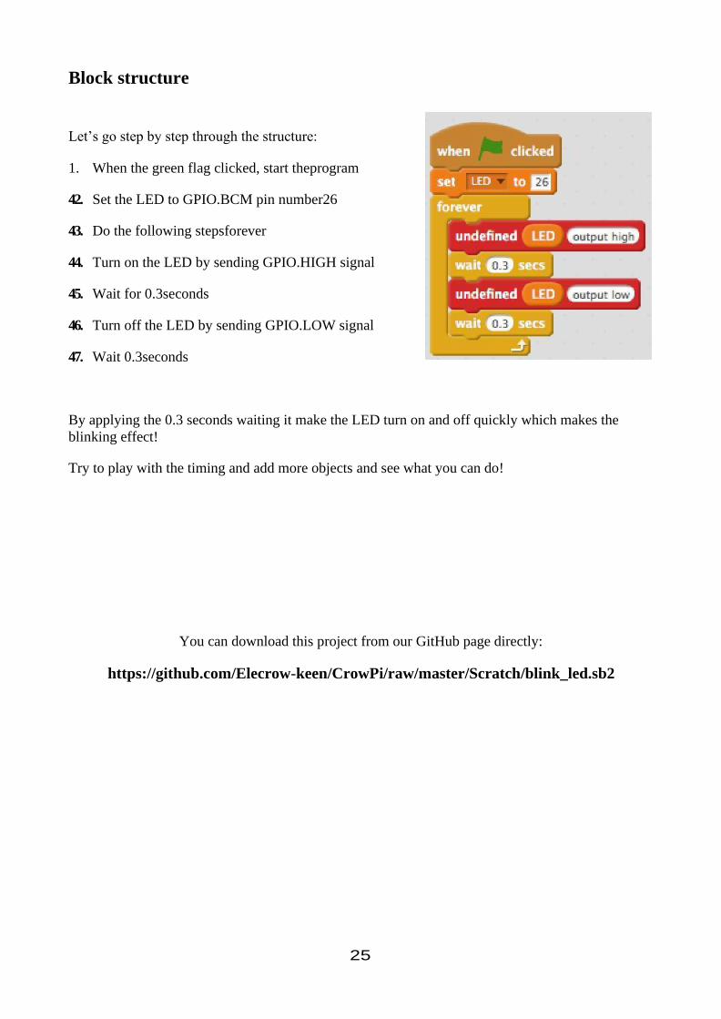
Let’s go step by step through the structure:
1. When the green flag clicked, start theprogram
42. Set the LED to GPIO.BCM pin number26
43. Do the following stepsforever
44. Turn on the LED by sending GPIO.HIGH signal
45. Wait for 0.3seconds
46. Turn off the LED by sending GPIO.LOW signal
47. Wait 0.3seconds
By applying the 0.3 seconds waiting it make the LED turn on and off quickly which makes the
blinking effect!
Try to play with the timing and add more objects and see what you can do!
You can download this project from our GitHub page directly:
https://github.com/Elecrow-keen/CrowPi/raw/master/Scratch/blink_led.sb2

26
Lesson 9 - Controlling sound
In this project we’ll learn how to detect sound using the sound sensor and then make the cat say if
sound been detected or not!
We’ll use the sound sensor which is located on GPIO.BCM pin number 24 as INPUT to detect if
loud noise heard around.
If loud noise is detected, the INPUT would be GPIO.HIGH and if no noise at all the INPUT would
be GPIO.LOW
We’ll also teach how to configure the sensitivity of the sound sensor to be able to recognize louder
or quieter sounds …
This module doesn’t require any changes to the switches.
Configuring the sound sensitivity

27
take a look at the picture above:
Our sensor contains a small controller that allows us to manually control the sensitivity of
the noise for sounds that are too quiet or too loud.
In order to make our script work we first must learn how to control that sensitivity option …
We’ll need to spin the little blue square that is rounded with red oval (in the picture) for
either left or right in order to control its sensitivity.
Spinning the sensitivity controller can be done by simply using any Phillips flat head screw
driver.
The best way to know what sensitivity level is suitable for you is by running the script and
clapping your hands once in a while or shout so you can see if there is an INPUT reaction
from the sensor which means he detects the loud noise.
If the sensor doesn’t detect the loud noise it means the sensitivity is too low and it won’t
react to it.
Increasing the sensitivity by spinning the blue square will solve this issue immediately.

28
Block structure
Let’s go step by step through the structure:
1. When the green flagged is clicked we start the
program
48. Set the sound sensor to GPIO.BCM pin number
24
49. Do the following actionsforever
50. If ( sound detected {GPIO.HIGH} ) then
51. Make the cat say “Sound detected!” + wait for 1
second.
52. Else ( sound not detected {GPIO.LOW})
53. Make the cay say “No sound …”
By applying the 1 second waiting, it won’t make the cat change from detected to not detected so
quickly and make the animation of the cat look more smoothly.
Try to change your own parameters or maybe make the cat do some other actions!
You can download this project from our GitHub page directly:
https://github.com/Elecrow-keen/CrowPi/raw/master/Scratch/sound.sb2