crystallography for geologists - school of · pdf filecrystallography for geologists ......
TRANSCRIPT

University of Edinburgh Mineralogy and Petrology
CRYSTALLOGRAPHY FOR GEOLOGISTS Course Notes for Min & Pet Geoffrey Bromiley & John Dixon 2009 Edition

CRYSTALLOGRAPHY FOR GEOLOGISTS Mineralogy & Petrology Crystallography Semester 2 Week 1 Crystallography crops up in some form in many different courses. Understanding the material in this booklet is essential for optical mineralogy and X-ray diffraction, both techniques used in many sub-disciplines of Earth Science. The symmetry and structure of crystalline phases not only record the history of Earth materials but changes in them may drive important reactions, both in the surface environment and in the deep Earth. The large-scale structure and properties of the Earth ultimately reflect the stability, chemistry and microstructure of minerals. These notes build on the crystallography course in Earth Dynamics. They have been written to provide a self-contained account of the bare essentials of crystallography that all Earth Scientists need to know. Students entering University at Second Year level should find these notes self-contained but they are strongly advised to read the Earth Dynamics handouts. This is a 7 hour crash course in basic crystallography, spread over two 'lecture' and 'practical' sessions, but which is further developed in the subsequent optics and mineralogy components of Min&Pet. We are providing you with the following material: ● This handout, which contains what we expect you to know in the form of a coherent account, and which follows material covered in the lectures. Bring it with you to the second lecture and both practicals. It also includes a list of terms and definitions and a summary of the specific learning objectives and skills that we expect you to be able to acquire by the end of the year. ● One own-time assignment, due in at the end of Week 5. ● Practical exercises which consolidate the lecture material, issued as self-contained exercises in the lab. The work done in these is an integral part of the course and may feature in the May exam. There is no distinction made in that exam between material and skills acquired from the lecture or in the practical or from your own reading. It is all potentially examinable. This principle applies throughout Min & Pet. Example examination questions are included in this Handout. You will probably also have to read at least parts of a text-book, and we recommend one of: • Introduction to Mineralogy, by WD Nesse, Oxford University Press, new from
£33.25. This book is better for Optics and Mineralogy in the opinion of JED but contains nothing on stereographic projections. However this Handout should contain all that you need to know on that topic.
• Mineral Science, by C Klein, Wiley, new from £30 Better for crystallography but does not recognise the trigonal system as separate
from hexagonal and is too condensed on Optics and not so good on Mineralogy as Nesse.
Geoff Bromiley, John Dixon1 January 2009 1 Based on a previous version of this text also prepared by Stephan Klemme
- 1 -

Contents 1. Introduction 3 2. Crystal faces and crystal symmetry 4 2.1 Faces, edged and interfacial angles 4 2.2 Crystal shape and crystal symmetry 5 2.3 The seven crystal systems 7 3. Stereographic projection 8 3.1 The stereographic sphere 8 3.2 The stereographic net 10 3.3 Zones and zone axes 11 3.4 Measuring a crystal 12 3.5 Habit and Form 13 3.6 Crystal axes, the Miller system and axial ratio determination 16 3.6.1 Procedure for indexing 17 3.6.2 Miller indices 18 3.6.3 General pole and general form: (hkl) and {hkl} 20 3.6.4 The law of rational intercepts 21 3.6.5 The law of constancy of interfacial angles 21 3.6.6 Calculating axial ratios 21 3.6.7 Indexing other faces. The zone law and addition rule 24 4. The seven crystal systems defined by their unit repeats and inter-axial 25 angles: The 32 crystal classes 5. Crystal lattices 28 5.1 Introduction: lattice + motif = structure 28 5.2 The Fourteen Bravais Lattices 29 5.3 Basics of X-ray diffraction ` 31 6. Crystal structure 33 6.1 Introduction: Point group + lattice type = space group 33 Crystallography learning objectives 34
- 2 -

1. Introduction Almost the entire Earth is crystalline. Crystals are a form of matter in which arrangements of atoms are repeated with almost perfect regularity, almost endlessly in three dimensions. If we could shrink ourselves down below the size of an atom and move around through the structure of a crystal, the atomic scenery around us would seem extraordinarily repetitive. In the most perfect natural crystals we would find less than one defective repeat unit (unit cell) in every 108. Imagine a society in which only one in a hundred million people was different to the rest and the other 99 999 999 of us were exactly the same! This sub-microscopic world is totally different to the heterogeneous, irregular, macroscopic world which we can see around us, and it has very special properties. To understand the Earth as a whole we must also understand its constituent parts, and most of those parts have properties which depend strongly on their crystalline character. Even those parts of the Earth which are liquid (for example silicate liquids in magmas and aqueous solutions in sediments or on the surface) have chemical compositions which are largely controlled by reactions with crystals. In some cases, liquids may have structures that appear similar to those of rock-forming minerals, albeit lacking the longer-range order characteristic of crystalline materials. Identifying crystalline varieties of minerals which grow under particular pressure and temperature conditions is one our main sources of knowledge about the conditions under which rocks form, both near the surface and in the deep Earth. The way crystals respond to pressure (their compressibility) and temperature (expansivity) are fundamental properties of matter which we need to know if we wish to calculate what assemblages of minerals are likely to be stable under any particular pressure and temperature conditions. Special properties of crystals, particularly the ways in which they transmit light and diffract X-rays, are applied routinely in many branches of science. A knowledge of some of the fundamental features of crystalline matter is essential for understanding many aspects of geology, geophysics and environmental geoscience. This course is mainly concerned with the relationship between crystal symmetry as shown by the external form (morphology) and optical properties of crystals, and crystal structure, the underlying arrangement of atoms. Crystal symmetry can be deduced from the morphology using very simple techniques which range from hand specimen observation to the use of instruments (goniometers) which measure the angles between crystal faces very accurately, and from crystal optics using the polarizing microscope. Determination of crystal structure, in contrast, requires the use of more sophisticated measurements involving the intensity of the diffraction of X-rays (or in some cases neutrons) by planes of atoms in the structure, and the details of this are beyond the scope the courses provided by Geology & Geophysics. However, each crystalline substance has its own distinctive X-ray diffraction pattern, providing a 'fingerprint' for identification which is used widely in the Earth Sciences. These courses will provide you with the basic knowledge you need to understand the character of these X-ray fingerprints. Crystal symmetry and crystal structure are linked by rules of repetition known as space groups which describe the restricted number of ways (230) in which equivalent groups of atoms can repeat in 3D space. These bring order to the immense chemical and structural variety of crystalline substances and link morphology, crystal symmetry, X-ray diffraction and structure together. There are many hundreds of thousands of crystalline substances, of which about 3500 form by geological processes and are therefore called minerals. The atomic structure of most minerals has been worked out using X-ray diffraction. The great pioneers in the determination of crystal structures were the father-and-son team of William H. Bragg and W. Lawrence Bragg. They were awarded the 1915 Nobel Prize for Physics for their work. Because minerals could be obtained as good quality crystals, and had structures which were challenging
- 3 -

yet could be solved using the techniques of the day, many of their studies were of minerals. By the 1930s, the structures of virtually all the important rock-forming minerals had been solved. Once the atomic structure of complex inorganic materials had been worked out the understanding of the solid state progressed rapidly, leading to the present day 'silicon age'. In the 1950s, with improvements in technique and with the appearance and increasing power of computers, crystallographers moved on to solve the structures of the immensely complex organic molecules which are essential to the phenomenon we call 'life', laying the foundations of modern biotechnology. Alongside mathematics, crystallography is now one of the only truly interdisciplinary scientific techniques. 2. CRYSTAL FACES AND CRYSTAL SYMMETRY 2.1 FACES, EDGES AND INTERFACIAL ANGLES We could start by considering the atomic structure of crystals, because the symmetry of their structure is in many ways the same as the symmetry of their external form. However, the repeat distance of the building blocks of structure (the unit cell) is extremely small (about 1 nanometer (nm) or 10-9 m for many silicate minerals, so that a 1 mm cube contains 1018 unit cells) and most of us find it easier to understand symmetry using the external morphology of crystals that we can see for ourselves. Therefore, it is useful to take the historical route of understanding the external shape of crystals first, before we burrow into their interiors at the atomic scale. The important underlying principle is that we let the crystals tell us about themselves. When they grow, provided they are not hindered in any way by another surface, crystals naturally tend to develop regular, nearly smooth faces which meet other faces to form edges. The beauty and regularity of crystals fascinated early scientists. They began the systematic study of crystals by measuring their interfacial angles. Interfacial angles are measured between imaginary lines drawn at right angles to the faces, called face normals (Fig. 1). In 1669 Nicolaus Steno recognized that the interfacial angles between corresponding pairs of faces were constant from one example of a particular mineral species to another, and proposed a Law of Constancy of Angle. In 1784 René Haüy noted that the same rule applied to the cleavage fragments produced by breaking larger crystals, whatever the size of the fragments, and proposed that crystals were made up of tiny, indivisible building blocks which he called 'molécules intégrantes'. While we now know that these basic building blocks are actually divisible, into atoms, the concept of repetition of building blocks of fixed shape is essentially correct. We call these unit cells. Haüy published beautiful drawings such as Fig. 2, showing how crystals of calcite could be built up by stacking little rhombohedral units. All the habits (real crystal shapes) of calcite could be developed in this way. Geometrically, Haüy's interpretation is perfectly correct, although we do not today imagine whole 'blocks' (unit cells) of structure being missed out to produce a face of a given slope. We now know that the unit cell is divisible, and made of atoms, and we imagine faces forming as planes which cut across the structure in directions governed by the repeat unit of the structure. We will return to this later.
- 4 -

Fig.1 (far left) shows a crystal showing face normals and the interfacial angles between them.
Fig. 2 Haüy's 1784 drawing of a crystal of calcite, with the habit known as 'dog-tooth spar', illustrating how the crystal could be built out of indivisible rhombohedral units.
2.2 CRYSTAL SHAPE AND CRYSTAL SYMMETRY Although natural crystals are sometimes nearly perfectly symmetrical, there is often no obvious symmetry. Fig. 3 shows two similar crystals which differ only in terms of the development of the crystal faces. One crystal (a) has perfectly bilateral symmetry (labelled m), the other (b) only a hint of the same symmetry. The symmetry of these crystals appears different. Note, however, that angles between respective faces in both crystals remain the same. m (a) (b)
a b
c d
c^d
b^c
a^b
a^d
Fig. 3 (a) Crystal showing ideal mirror symmetry. The faces on either side of the mirror plane are exact mirror images (b) Crystal with equivalent faces to (a) but unequally developed. The symmetry of (a) is known as reflection or mirror symmetry. Each face in (a) has its exact reflection equivalent, but in (b) faces which are obviously related by reflection in (a) are differently developed, and the symmetry is lost. Fig. 4 shows a selection of idealized crystals with perfect symmetry. Three different types of symmetry can be distinguished, mirror planes, rotation axes and a centre. [It turns out that a fourth combined element of symmetry, a rotoinversion or more simply, inversion axis, is needed to fully bring out the inherent symmetry in some tetragonal crystals, which would have been otherwise placed in a less symmetrical system, despite having a tetragonal lattice.]:
- 5 -

• Mirror symmetry: imagine slicing the idealized crystal along a plane so that the two halves are exact mirror images of each other. The plane is called a mirror plane (abbreviated to m-plane). On Fig. 4 m-planes are shown (unconventionally) as dotted lines or as slices through the crystal. • Rotational symmetry: image holding the ideal crystal between finger and thumb and rotating it. As it rotates it will look exactly the same either once, twice, three times, four times or six times. The line about which the crystal rotates is called a 1-, 2-, 3-, 4- or 6-fold symmetry axis (1-fold really means that it looks the same only once, so it really does not have any rotational symmetry. However there is a reason for including it which will become clear later). The axes are sometimes called diad, triad, tetrad or hexad axes. No other values are possible in crystallography. There are standard symbols for rotational symmetry, defined in the International Tables for X-ray Crystallography: 2-fold: , 3-fold , 4-fold: , and 6-fold: You can imagine holding the crystals shown on Fig. 4 at the points marked by the symbols and rotating the crystal around the axis between them. • Centre of symmetry: Imagine yourself burrowing from any face through the dead centre of the crystal and out on the other side. If you did this for every face and in each case found yourself on an exactly parallel face, the crystal would have a centre of symmetry. In an ideal crystal every point on the edges, or the corners of each face, would be repeated on the other side of the crystal by passing through the centre. Crystals with centres are said to be centrosymmetric, those without are non-centrosymmetric.
Fig. 4. Selected crystals,showing their symmetry elements. Holosymmetric have the maximum symmetry possible for their crystal system.
- 6 -

2.3. THE SEVEN CRYSTAL SYSTEMS Using real crystals and methods that we shall use in Sec. 3, the early crystallographers found that they could assign crystals to one of six crystal systems (Table 1). One of these (the hexagonal system) is usually divided into two giving a seventh system (the trigonal). Each system has minimum level of symmetry and is divided into symmetry classes; the one with the maximum symmetry is known as the holosymmetric class, and other classes are said to exhibit reduced symmetry. In all systems except the triclinic the classes are defined by various combinations of reflection and rotational symmetry. There are only 32 possible combinations of symmetry operations, leading to a total of 32 crystal classes, distributed as shown in Table 1. We will explain later why there are only a small number of possible combinations of symmetry operations. Table 1 ___________________________________________________________________ System Minimum symmetry Maximum symmetry No. of
classes Triclinic None A centre 2 Monoclinic One 2-fold axis or one
m-plane One 2-fold axis at right angles to a m-plane, and a centre
3
Orthorhombic Two m-planes and one 2-fold axis
Three 2-fold axes, three m-planes and a centre
3
Tetragonal One 4-fold axis One 4-fold axis, 5 m-planes and a centre
7*
Cubic Four 3-fold axes and three 2-fold axes
Four 3-fold, three 4-fold, six 2-fold axes, 9 m-planes and a centre
5
Trigonal One 3-fold axis One 3-fold axis normal to three 2-fold axes
5
Hexagonal One 6-fold axis One 6-fold axis, six 2-fold axes, seven m-planes and a centre
7
* It turned out that there were two symmetrical objects that had four-fold symmetry that could not be expressed purely by combinations of rotation axes, mirror planes and a centre. These could between them account for only five tetragonal classes, and 30 in total. A new symmetry element, an Inversion Axis, was introduced to accommodate all 32. It is explained below Rotation with inversion: One-, two-, three-, four-, and six-fold rotations can be combined with inversion and are known as rotoinversion symmetry elements, or inversion axes. Fig. 5 illustrates the combination of rotation with inversion. To differentiate between normal rotation and rotoinversion, rotoinversion is symbolized with a bar symbol⎯ added to the rotational symbol. A three-fold rotoinversion is therefore symbolized as⎯3 (read “bar three”) and is usually referred to as an inverse triad. As for simple rotation, there are standard symbols for rotoinversion symmetry, defined in the International Tables for X-ray Crystallography: ⎯1 (no symbol), ⎯2 = m (no symbol) ⎯3 ⎯4 ⎯6
- 7 -
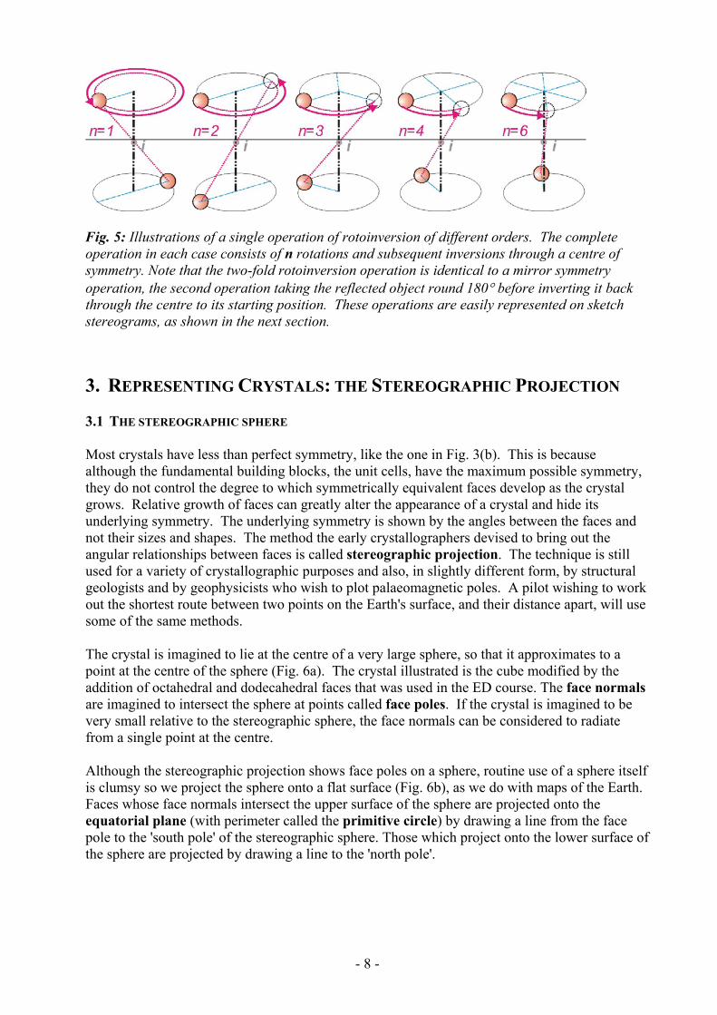
Fig. 5: Illustrations of a single operation of rotoinversion of different orders. The complete operation in each case consists of n rotations and subsequent inversions through a centre of symmetry. Note that the two-fold rotoinversion operation is identical to a mirror symmetry operation, the second operation taking the reflected object round 180° before inverting it back through the centre to its starting position. These operations are easily represented on sketch stereograms, as shown in the next section. 3. REPRESENTING CRYSTALS: THE STEREOGRAPHIC PROJECTION 3.1 THE STEREOGRAPHIC SPHERE Most crystals have less than perfect symmetry, like the one in Fig. 3(b). This is because although the fundamental building blocks, the unit cells, have the maximum possible symmetry, they do not control the degree to which symmetrically equivalent faces develop as the crystal grows. Relative growth of faces can greatly alter the appearance of a crystal and hide its underlying symmetry. The underlying symmetry is shown by the angles between the faces and not their sizes and shapes. The method the early crystallographers devised to bring out the angular relationships between faces is called stereographic projection. The technique is still used for a variety of crystallographic purposes and also, in slightly different form, by structural geologists and by geophysicists who wish to plot palaeomagnetic poles. A pilot wishing to work out the shortest route between two points on the Earth's surface, and their distance apart, will use some of the same methods. The crystal is imagined to lie at the centre of a very large sphere, so that it approximates to a point at the centre of the sphere (Fig. 6a). The crystal illustrated is the cube modified by the addition of octahedral and dodecahedral faces that was used in the ED course. The face normals are imagined to intersect the sphere at points called face poles. If the crystal is imagined to be very small relative to the stereographic sphere, the face normals can be considered to radiate from a single point at the centre. Although the stereographic projection shows face poles on a sphere, routine use of a sphere itself is clumsy so we project the sphere onto a flat surface (Fig. 6b), as we do with maps of the Earth. Faces whose face normals intersect the upper surface of the sphere are projected onto the equatorial plane (with perimeter called the primitive circle) by drawing a line from the face pole to the 'south pole' of the stereographic sphere. Those which project onto the lower surface of the sphere are projected by drawing a line to the 'north pole'.
- 8 -
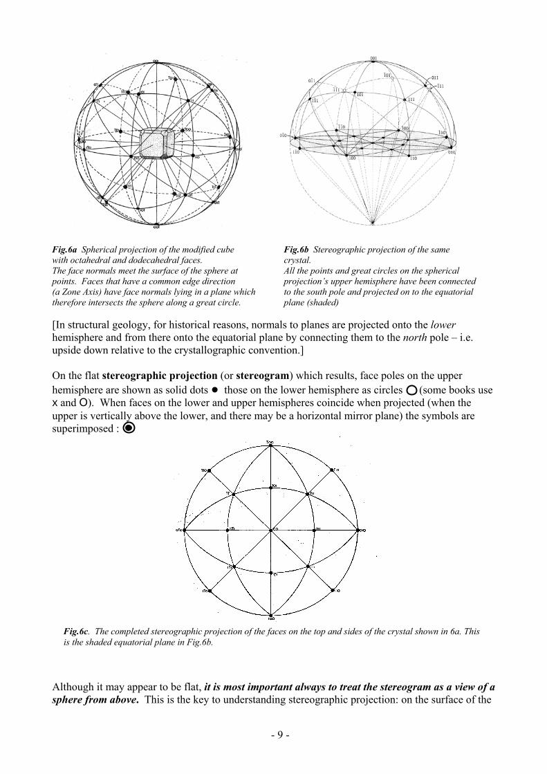
Fig.6a Spherical projection of the modified cube Fig.6b Stereographic projection of the same with octahedral and dodecahedral faces. crystal. The face normals meet the surface of the sphere at All the points and great circles on the spherical points. Faces that have a common edge direction projection’s upper hemisphere have been connected (a Zone Axis) have face normals lying in a plane which to the south pole and projected on to the equatorial therefore intersects the sphere along a great circle. plane (shaded) [In structural geology, for historical reasons, normals to planes are projected onto the lower hemisphere and from there onto the equatorial plane by connecting them to the north pole – i.e. upside down relative to the crystallographic convention.] On the flat stereographic projection (or stereogram) which results, face poles on the upper hemisphere are shown as solid dots ● those on the lower hemisphere as circles (some books use x and O). When faces on the lower and upper hemispheres coincide when projected (when the upper is vertically above the lower, and there may be a horizontal mirror plane) the symbols are superimposed :
Fig.6c. The completed stereographic projection of the faces on the top and sides of the crystal shown in 6a. This is the shaded equatorial plane in Fig.6b.
Although it may appear to be flat, it is most important always to treat the stereogram as a view of a sphere from above. This is the key to understanding stereographic projection: on the surface of the
- 9 -

sphere you can travel only along curved lines, and all distances are measured and stated as angles, swept out from the centre of the sphere. You can always reconstruct the slope of a face if you remember that it will be parallel to a plane which is a tangent to the sphere at the point where the face pole is marked. 3.2 The Stereographic Net To construct a stereographic projection of a crystal we measure the interfacial angles (as described in Sec. 3.4) and make use of a stereographic net (Fig. 7). There are several types of stereographic net – the crystallographer's sort is called a Wulff net. It is slightly different to the equal area net that structural geologists use. You can see that the outer circle (the equatorial or primitive circle) is calibrated at 2° intervals. The primitive circle is a circular section of the sphere, which happens to be horizontal. There are an infinite number of such circular sections, or great circles. On the net they are drawn at 2° intervals from the horizontal primitive circle to a vertical great circle which projects as a straight line.
Fig.7 The Wulff Net
Fig.8a Fig.8b Fig.8a shows a series of planes intersecting along the horizontal line equivalent to the line of intersection of the Greenwich Meridian and the Equator. They intersect the sphere as great circles and when the points along these great circles are joined to the south pole they project as segments of circles on the equatorial plane of projection. Fig.8b shows how the small circles are constructed. These are lines of equal angle measured from the same 12 o’clock-6 o’clock horizontal axis shared by all the great circles. They too project as segments of circles and are plotted at 2˚ intervals. The small circle at 90˚ from the 12 o’clock—6 o’clock line is itself a great circle, a vertical, east-west great circle that plots as a straight line on the equatorial plane. The angle between any two face poles on a stereogram can be measured by finding the great circle on which they both lie, and counting the angular divisions between them. When you draw great circles on a stereogram use a continuous line for great circles on the upper hemisphere, and a
10

broken line for great circles on the lower hemisphere. Any one, inclined, great circle continues round the sphere and is shaped like a rugby ball in projection. Navigators use great circles to find the shortest route between two points on the surface of the Earth. One sixtieth of a degree (one minute of arc, ') on the Earth's surface is called a nautical mile. 3.3 ZONES AND ZONE AXES When we plot a stereogram we imagine the crystal to be placed in the centre of the stereographic sphere (Fig. 6a). We could imagine the crystal in any orientation at all within the sphere, and start our plot with the crystal placed at random. However, most of us, including crystallographers, like to make life as simple as possible. We let the crystal tell us how we should orientate it within the sphere so that it displays its symmetry most clearly. When you look at any crystal you will always find some sets of edges which are mutually parallel. The crystal in Fig.6a has several sets. A set of faces with mutually parallel edges is called a ZONE, and the common edge direction is called the ZONE AXIS. Sometimes one zone is more conspicuous than the others, as in the case of a crystal which is elongated in one direction (Fig. 9). In a crystal like this we call the set of faces with the longest mutually parallel edges the prism zone, and we would normally imagine the crystal set up in the stereographic sphere with the prism zone vertical. Even if the crystal is equidimensional (the modified cube in Fig.6a for example) we will make much better progress if we place the crystal in the stereographic sphere with a zone axis vertical. Face normals for second zone Second zone axis Face normals for the prism zone Prism zone axis Fig 9. Simple crystal showing two zones of faces, their zone axes, and their sets of face normals each lying in a single plane Zones of faces have the important property that their face normals always lie in a single plane, which is at right angles to the zone axis. This means that the face poles of any zone always lie on a great circle of the stereogram, which is also at right angles to the zone axis. Zone
11

axes may or may not be at right angles to each other. If we place a crystal with a prominent prism zone (like that in Fig. 9) at the centre of the stereographic sphere, with the mutually parallel edges of faces in the prism zone (the zone axis) vertical, all the face poles for the prism zone will plot on the equatorial circle (Fig. 10) and the faces in the second zone, which has a horizontal axis, will plot on the vertical N-S great circle, as shown.
Fig.10 Stereogram of the crystal in Fig 9.
Second Zone
Prism Zone 3.4 MEASURING A CRYSTAL light source
telescope
Fig. 11 The face normals for a zone always lie on a great circle, at right angles to the zone axis. If the crystal is set on the turntable of a goniometer so that a zone axis is vertical, the normals will bisect the angle between the light source and the telescope in turn, and the interfacial angles can be measured exactly. Zones of faces are important when we measure interfacial angles exactly. The simplest, but inaccurate way of doing this is to use a contact goniometer. However, for accurate measurements an instrument called an optical goniometer is used. Such instruments are today mainly of historical interest but they demonstrate the concept of zones very well. The crystal is set so that a zone axis (the prism zone in Fig. 11) is exactly vertical, using a pair of adjustable arcs. The face normals for all the faces in the zone will then be horizontal. If the turntable is rotated the collimated beam from the light source will be reflected from each face in the zone in turn, when its face normal bisects the angle between collimator and telescope. The turntable has a scale and angles can easily be measured to ±1' (1 minute). When all the faces in a complete 360° rotation have been measured, the crystal is removed from the arcs and replaced with another zone axis vertical. This is repeated until as many zones as necessary have been measured. The crystallographer then has a series of lists of interfacial angles.
12

Victorian crystallographers had a lot of fun doing this sort of thing. They were very careful and many of the names we use for common minerals reflect the measurements they made (orthoclase, microcline, anorthite, for example). They produced whole books devoted to the tabulation of interfacial angles, full of careful drawings of crystals. It was a necessary step in the understanding of crystal symmetry and laid the foundations for the classification of minerals at a time when accurate chemical analysis was not available. 3.5 HABIT AND FORM We now know that Haüy’s inspired proposal was essentially correct, that crystals could be constructed from stacked identical blocks, with the blocks corresponding to our modern concept of the unit cell. Hauy also realised that the faces on a crystal had simple relationships to one another, with the steps that created sloping faces tending to have small whole numbers of blocks on the tread and the riser. The crucial implication of this principle is that the underlying repeating structure of the crystal is expressed by the angles between the crystal faces, not their size. [This leads to two important laws in crystallography; the Law of the Constancy of Interfacial Angle and the Law of Rational Intercepts which will be explained more fully when we connect the external form of crystals to the underlying lattice concept in Section 5]. Up to this point we have approached crystalline material from the outside, recognising symmetrical relationships between faces, while acknowledging that it is the angles that actually reflect the underlying symmetry of the internal structure. Somewhat mysteriously, many crystalline substances actually grow symmetrically so that equivalent faces related by symmetry are of similar sizes. (Snowflakes are the classic example – how do opposite sides of the flake know what each is doing so that the pattern is symmetrical?) Nevertheless, crystals of the same mineral do not always grow identical forms even though the angles between structurally equivalent faces may be the same. Habit is the name given to a consistent type of crystal shape and crystallographers have long recognised that one mineral can show several different habits. (e.g. prismatic, tabular, pyramidal) Calcite CaCO3 is the classic example, growing sometimes as sharply pointed pyramids as dog-tooth spar or rather less commonly as flattened rhombohedra – nail-head spar. Calcite may also grow as six-sided prisms. The reasons for the diversity are not well understood but must relate to the chemical environment at an atomic scale, at the growing crystal surface. In essence, some crystal faces (or lattice planes) are more favoured sites of growth than others, so the crystal extends preferentially in certain directions. A crystal may also develop irregularly, if its growth is obstructed. Form is used as a technical term in crystallography for a specific set or arrangement of faces related by symmetry. A crystal is a three-dimensional object bounded by faces and these can be grouped into forms. These can be open forms, such as a pair of parallel faces related by a centre of symmetry, (technically known as a pinacoid), or a tetragonal prism (an open four-sided tube), or closed forms, such as a cube. It is important to be familiar with the terminologies for both habit and form as they occur in all descriptive mineralogical texts. It is also important to appreciate the difference between the two. A mineral’s habit essentially reflects which form or forms are most prominently developed. Some terms for habit are the same as those for form: prism / prismatic. Thus quartz can occur with two common forms: a di-trigonal prism, with six sides, terminated by (i.e. with the end of the crystal formed by) a di-trigonal pyramid, with six faces. If the prism dominates and the crystals are long and thin, the habit is prismatic. If the prism sides are extremely short and the quartz presents an array of six-sided points, the habit would be described as pyramidal. Other habit terms are more general and are illustrated below:
13

BARREL SHAPED PRISMATIC ACICULAR
PLATY TABULAR
EQUANT
Fig.12 Habits
(Other terms for habit are not so directly related to the crystal forms. Fibrous (as in the asbestos form of serpentine) is an extreme example of prismatic, but reniform (kidney shaped as in the case of hematite), botryoidal (like a bunch of grapes, as in chalcedonic silica) or stalactitic imply that no obvious crystal faces are developed. All uncertainties introduced by variable habit and uneven development are overcome by the use of the stereographic projection, which allows the angular relationships between crystal faces to be displayed and so displays true symmetry. Sketch stereograms, showing the distribution of sets of faces all related by the symmetry of the crystal, and the symmetry elements themselves, are very useful. There is a straightforward procedure for doing this. To bring out the operation of the symmetry elements we need to show their effect on a single face (represented as usual by its pole). This face must not be in a special position – e.g. parallel or perpendicular – to the symmetry axis or mirror plane otherwise the operation of that element may not actually produce an additional face. The simplest example of an unsuitable face is a face at right angles to a rotation axis. The axis has no effect on it. This leads to two further terms:
Special Form: a set of faces with a special orientation relationship to the symmetry elements which relate them to each other, i.e. that the faces are parallel or perpendicular to the element or elements in question. Thus the set is not uniquely diagnostic of the full symmetry of the group of symmetry elements present. General form: a set of faces related to one another by the operation of one or more symmetry elements that do not bear a special relationship to the elements and so reveal the full operation of the group of symmetry elements present.
The convention for displaying the operation of a group of symmetry elements is to use as a general form a face which is in the lower right hand part of the stereogram (a general pole), close to x-axis and close to the primitive circle, not parallel to or perpendicular to or equidistant from, any axis or plane of symmetry. (It represents a face which will make a positive intersection on the x, y and z axes. This face will have Miller Indices (hkl), or (hkil) in the case of trigonal or hexagonal systems (see later).
14

For all systems except trigonal and hexagonal with at least two axes at 90° is also useful, but not essential, to sketch in two light lines NS and EW on the sketch stereogram as guide-lines, and extend them beyond the primitive circle to make clear they are not mirror planes. With trigonal and hexagonal systems it is likewise useful to sketch in three or six equally spaced spokes, with one representing the conventional direction of the y-axis out to the right, as this enables you to repeat the position of the hkl face three or six times accurately as in the examples below. The rotation and inversion axes are placed on the stereogram in their conventional positions and should be shown with their conventional symbols. 1-fold, single 3-fold, 4-fold and 6-fold axes are placed vertically and so plot in the centre. A single 2-fold axis, characteristic of the monoclinic system, is placed horizontally out to the right, (coincident with the y-axis). The four triads, characteristic of the cubic system, are equidistant from the three mutually perpendicular axes x, y and z, and so plot in the middle of each quadrant. A mirror plane is conventionally represented by a thicker line or great circle. It is important to remember that symmetry elements operate on each other, and also that elements may combine to automatically generate further elements, as in 13c below. Fig. 13. Sketch stereograms showing the operation of a selection of symmetry elements. 4 4/m 4/mmm 13a. Operation of the tetrad axis alone. 13b. Addition of a horizontal 13c. Addition of a vertical mirror (tetragonal pyramid) mirror plane creates four plane NS is repeated by the 4-fold extra faces underneath. axis to give an EW mirror. An (tetragonal bipyramid) additional pair of mirrors at 45° to the others is generated automatically, giving 16 faces in all. (di-tetragonal bipyramid) 2/m 6 13d. Diad plus mirror plane at 90° 13e. Hexad (6-fold rotation axis) cont…
15
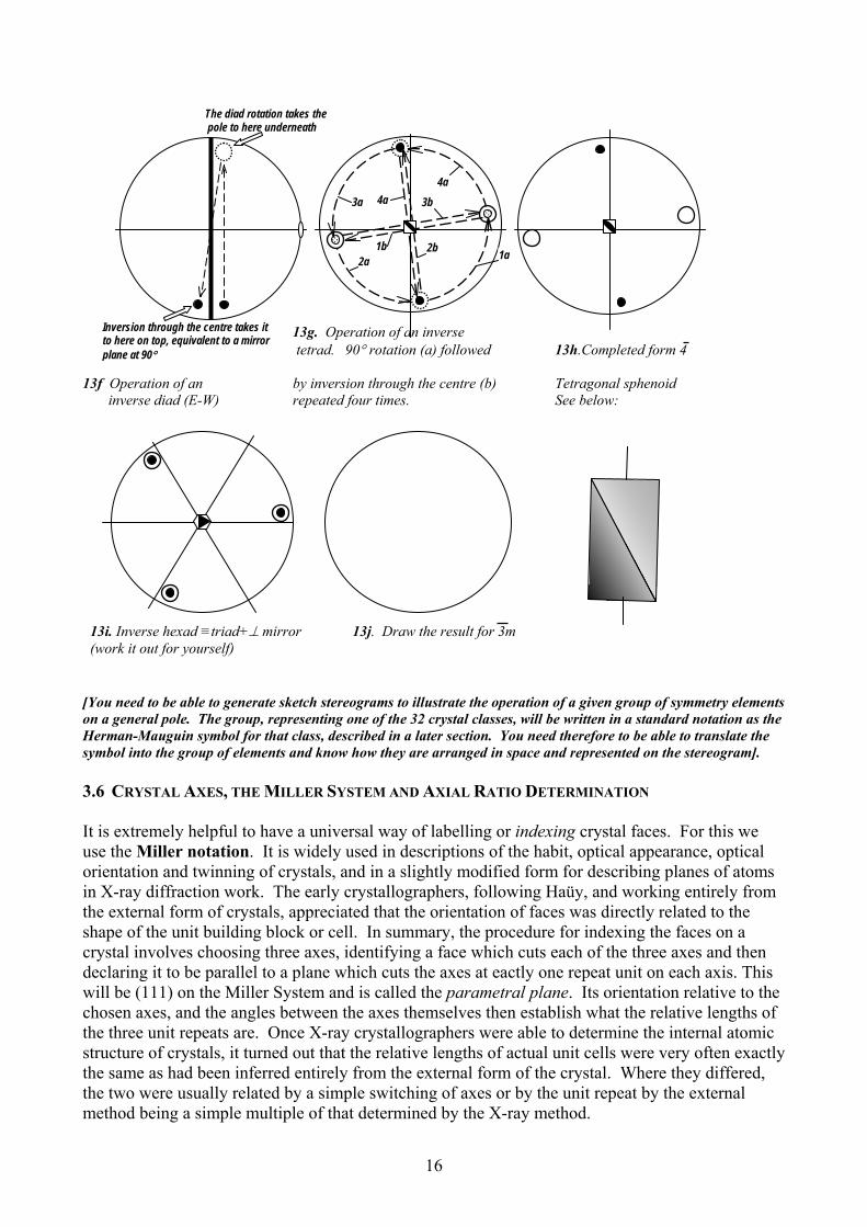
13g. Operation of an inverse
tetrad. 90° rotation (a) followed 13h.Completed form 4 13f Operation of an by inversion through the centre (b) Tetragonal sphenoid inverse diad (E-W) repeated four times. See below:
1b
13i. Inverse hexad ≡triad+⊥ mirror 13j. Draw the result for 3m (work it out for yourself)
4a 4a
3b 3a
2b 2a 1a
Inversion through the centre takes it to here on top, equivalent to a mirror plane at 90°
The diad rotation takes the pole to here underneath
[You need to be able to generate sketch stereograms to illustrate the operation of a given group of symmetry elements on a general pole. The group, representing one of the 32 crystal classes, will be written in a standard notation as the Herman-Mauguin symbol for that class, described in a later section. You need therefore to be able to translate the symbol into the group of elements and know how they are arranged in space and represented on the stereogram]. 3.6 CRYSTAL AXES, THE MILLER SYSTEM AND AXIAL RATIO DETERMINATION It is extremely helpful to have a universal way of labelling or indexing crystal faces. For this we use the Miller notation. It is widely used in descriptions of the habit, optical appearance, optical orientation and twinning of crystals, and in a slightly modified form for describing planes of atoms in X-ray diffraction work. The early crystallographers, following Haüy, and working entirely from the external form of crystals, appreciated that the orientation of faces was directly related to the shape of the unit building block or cell. In summary, the procedure for indexing the faces on a crystal involves choosing three axes, identifying a face which cuts each of the three axes and then declaring it to be parallel to a plane which cuts the axes at eactly one repeat unit on each axis. This will be (111) on the Miller System and is called the parametral plane. Its orientation relative to the chosen axes, and the angles between the axes themselves then establish what the relative lengths of the three unit repeats are. Once X-ray crystallographers were able to determine the internal atomic structure of crystals, it turned out that the relative lengths of actual unit cells were very often exactly the same as had been inferred entirely from the external form of the crystal. Where they differed, the two were usually related by a simple switching of axes or by the unit repeat by the external method being a simple multiple of that determined by the X-ray method.
16

3.6.1 Procedure for Indexing Step 1: The first step is to assign a set of three coordinate (or crystal) axes. The axes should be: (1) Parallel to conspicuous zone axes, or (sometimes but not often) possible zone axes. Possible zone axes are sets of edges which would be parallel if crystal faces were projected to intersect, although crystal growth may not have produced these intersections (Fig. 14). (2) Parallel to prominent elements of symmetry (usually directional ones, like symmetry axes, sometimes mirror planes) (3) At right angles if possible. Fig. 14 Zone axes and possible zone axes. The heavy line is the zone axis or possible zone axis. In crystals a and b there is an obvious vertical prism zone which appears to be a 4-fold rotation axis, or at least the intersection of two mirror planes. It would be chosen as the z-axis. In crystal c the solid line is not technically a zone axis because there are no edges parallel to it, but it is a direction of elongation and the direction of at least one element of symmetry and is also a potential zone axis. It would still be an obvious choice for the z-axis. Step 2: The next step is to identify a crystal face that, when extended, would cut all three of the axes as near equally as possible. In the example below, a prismatic crystal has eight faces parallel to the prism axis, chosen as the z axis, four sloping faces forming a pyramid and a face truncating the top of the prism. The x and y axes have been chosen to be perpendicular to one set of the prism faces. The sloping face P is the obvious choice of a plane to define the unit intercepts on the axes, a on x, b on y and c on z. Fig.15 Choosing a parametral plane.
-y
-z
+z
a b
c
P-x
+x
+y
17

3.6.2 Miller Indices Step 3: The next step is to index the faces according to the Miller System. The formal definition is as follows: In the Miller System a face with Miller Index (hkl) is parallel to a plane that makes intercepts of a , b, and c on the x, y and z axes, where a, b and c are the unit repeats. h k l The individual terms h, k and l are the Miller Indices. (hkl) is the Miller Symbol. Note that the h, k and l are underneath in the definition. The parametral plane has Miller Indices 1,1,1 because it makes unit intercepts by definition. a/h = a so h = 1 and so on. Faces that are parallel to an axis intersect it at infinity and will have a Miller Index for that axis of zero. A face parallel to the y axis and the z axis, as in the case of the front prism face in Fig.15, will cut the x axis, let us say, at one x-unit from the origin, i.e. at a. Its intercepts will be a, ∞ and ∞ on the three axes. Hence a/h = a b/k = ∞ c/l = ∞ ∴ h = 1 k = 0 l = 0 and the Miller Symbol is (100). In fact Miller Symbols are always reduced to the simplest whole-number form, or lowest common denominator, so that (222) becomes (111) to which it is parallel anyway. It does not therefore generally matter what intercept we take for a face which cuts only one axis and is parallel to the other two because (300) or (500) both reduce to (100). (From now on Miller Indices will be written in normal type as (hkl).) Note that the Miller System works whether the axes are at right-angles or not. A zero in the symbol means that the plane is parallel to that axis. The remaining aspect of indexing concerns faces that make intercepts on the axes other than at one unit or infinity. For example, a face that intersects the x axis at 3a, the y axis at 2b and is parallel to the z axis will have the Miller Symbol (230), [note not (320]. From the definition: a/h = 3a, b/k = 2b and c/l =∞ from which h = ⅓, k = ½ and l = 0. The Miller Symbol is, therefore, in raw form: (⅓,½,0) which when reduced to the smallest whole number form needs to be multiplied all through by 6, giving (230). The simplest way to appreciate this effect of the definition is to note that (230) is a plane which makes intercepts of a half an x-unit on x (i.e. a/2), a third of a y-unit on y (b/3) and is parallel to z. This is illustrated below, a view looking down the z-axis edge-on to the (230) plane. It is parallel to the plane with intercepts 3a and 2b on x and y and therefore has the same symbol. Fig.16
x
y 2b b
3a
a ⁄ 2
a
2a
b ⁄ 3 z
(230)
18

Faces which intersect the negative extension of an axis have negative indices, written with a short line above the number and spoken as “bar one” “bar three” etc. In summary: (111) is the plane cutting the x, y and z axes at the unit repeats a, b and c. (100) is a plane parallel to the y and z axes, and cutting the x axis. (010) is a plane parallel to the x and z axes, and cutting the y axis. (001) is a plane parallel to the x and y axes, and cutting the z axis. (110) is a plane cutting the x and y axes at a and b, the unit repeats, and is parallel to the z
axis. (321) is a plane cutting the x axis at a/3, the y axis at b/2 and the z axis at c. (121) is a plane cutting the negative end of the x axis at –a, the y axis at b/2 and the
negative end of the z axis at –c. [It is essential that you become completely familiar with the Miller system as it is used throughout mineralogy to describe mineral properties, particularly the identity of cleavage planes and the commonly adopted forms of crystals. You will also need to be aware how symmetry elements operate on faces that are identified by their Miller symbol.] On the next page is an important variation of the Miller system which is used for trigonal and hexagonal crystals.
19

Miller-Bravais Indexing in Trigonal and Hexagonal Crystals Trigonal and hexagonal crystals use an extension of the Miller system which introduces a third axis u at 120° to the x and y axes, which are themselves at 120° to each other and at 90° to the z axis. The Miller indices are then of the form (hkil). Because the first three, h, k and i, are in one plane and 120° apart, any plane that intersects them or their negative extensions will have intercepts that add up to zero. (See below) Thus h + k + l = 0. The benefit of this system is that it brings out the inherent three- or six-fold symmetry in the trigonal and hexagonal systems when the Miller symbols for faces related by symmetry are compared. This can be seen in the two alternative versions of a trigonal prism indexed the two ways in the stereogram.
y
Trace of plane parallel to z which makes equal intercepts on x and y. Note that it makes intercept a/2 on negative u
This plane would have intercepts: a/1 a/1 a/-½ c/∞ giving Miller-Bravais indices of (1 1 2 0)
x
a
a
a
-u
a/2
x
y
100 Miller 1010 Miller-Bravais
110 Miller 1100 Miller-Bravais
z
(u)
Miller: 010Miller-Bravais: 0110
Note that there is no obvious relationship between the three symbols in the Miller system but that in the Miller-Bravais the three symbols have the same three indices 1, 1 and 0, in all three possible combinations and are more obviously related.
3-Fold Axis Parallel to z
u 3.6.3 General Pole and General Form: (hkl) and {hkl} The Miller Symbol (hkl) [or (hkil) in a trigonal or hexagonal case] written in round brackets means a single general pole or face. When written in curly brackets, {hkl} it means all the faces of the general form created by operating the symmetry elements on (hkl).
How many faces are implied depends on what the symmetry elements are. In example 11d earlier (left), the crystal was tetragonal and the class was 4/m, which means that there are eight faces in the general form. Thus {hkl} means (hkl), (hkl), (hkl), (hkl), (hkl), (hkl), (hkl) and (hkl). In general a zero in the symbol implies a special form as in {hk0}.
20

3.6.4 The Law of Rational Intercepts (“Haüy’s Law”) Haüy studied many crystals and found that the intercepts of all their faces on the crystallographic axes (defined by the rules listed above) were simple fractions or multiples of the intercepts made by the parametral plane – the face given the Miller Symbol (111). Even in crystals in which there is a choice of face that can be called (111), (i.e. when there is more than one face in the +++ octant of the sphere that cuts all three axes), whatever the choice made, this same simple rule applied. Haüy called this relationship the Law of Rational Intercepts.It is formally stated as an extension to the definition of Miller Indices:
The intercepts made by the faces can be expressed as ah
, bk
, cl
where a, b and c are the unit repeats on the crystallographic axes, as defined by the choice of the parametral plane (111), and h, k and l are simple whole numbers or zero.
(Haüy saw this as reflecting the prevalence of sloping faces that spanned simple multiples of the building blocks - one up and two along being much more common than five up and seven along at each step. This is still an important observation even though we now recognise that faces are planes cutting through the atomic structure. We shall see that if we regard the corners of Haüy’s blocks as lattice points or points of identical atomic environment, then faces are planes of high lattice point density). 3.6.5 The Law of Constancy of Interfacial Angle (“Steno’s Law”) It should also now be clear that if the faces are controlled by the unit repeats which relate directly to the actual repeating structural unit in the crystal, then if the structure of two crystals is the same they will have equivalent faces at exactly the same angle to one another in all examples of that same substance, regardless of how well developed the faces happen to be. This can be stated simply:
In all crystals of the same substance, the angles between corresponding faces have a constant value.
3.6.6 Calculating Axial Ratios Choosing a face as the parametral plane (111), as in Fig.11, establishes the relative lengths of the unit repeats on the axes but not the actual size of the unit cell in the underlying structure. Crystallographers working from crystal faces calculate the axial ratio a:b:c. X-ray crystallographers determine the actual dimensions a, b and c. The convention is that the axial ratio is expressed in the form: a/b : 1 : c/b i.e. the unit repeats (if they are known) are divided through by b. The separate ratios a/b and c/b are calculated directly from the geometry of the faces which cut the axes, once they have been indexed. This is most easily done when the axes are all at right angles, as in the tetragonal and orthorhombic systems. (You need to be familiar with this procedure). It involves progressively more trigonometry for systems with axes at angles other than 90°, for which, consult the textbooks. (The cubic system has equal unit repeats on the three axes that are all at right angles so the axial ratio is 1:1:1 and thus is of no further concern.)
21

Crystals with axes at right angles The key to the procedure is to appreciate the significance of faces that cut two axes at one unit repeat from the origin and are parallel to the third, i.e. (110), (101) and (011). (101) (101) (101)
z
y x
Fig. 17a Fig.17b Fig.17c Consider the cubic crystal in Fig.17a, as was used to illustrate the stereographic projection earlier. The face O is the parametral plane (111) and is at equal angles to the three axes (54° 44′). Face (101) labelled d, cuts the x and z axes at the unit repeat a and is therefore at 45° from each axis. It is also 45° from the front face a which is (100) and the top face which is (001). Note also that the edges between (101), O and the side face a which is (010) are all parallel, and so these faces lie in a zone and will plot on a great circle, as shown in fact in Fig.6c earlier. Now consider two tetragonal crystals, 17b and 17c, which have a vertical 4-fold axis but no longer have triad axes or horizontal tetrads. They will have a square cross-section if viewed from above. They have equal x and y repeats but an unequal z-repeat. They show the same set of faces in the same zones but the angles involving faces that cut the z axis are different from the cubic case. The key feature is not the overall shape of the crystal but the slopes of the (101) faces relative to the z axis. In 17b the (101) face is steeply sloping which means that the z-repeat c must be larger than the x and y repeats a. In fact this crystal is also elongated in the direction of the z-axis as often happens, but this is not a necessary consequence of the relative lengths of a and c. Similarly, in 17c, the slope of (101) is shallower because now c is less than a. Note that (101), (111) and (010) retain their parallel edges as they still lie in a zone which includes faces on the far side and underside of the crystal. It is now straightforward to calculate the axial ratio c/a (identical to c/b) by considering the slope of (101) relative to the axes. z and⊥(001) zz and⊥(001) Fig.18 Projections viewed along the y-axis showing the traces (edge-on) of (101) and (001) for crystals 17b (left) and 17c (right).
(101)
c
a
⊥(101)
x
(001)
(001)
θθ
(101)c
θ θ a
⊥(101)
x
22

From the right-angles triangles in the diagram Fig.18, the angle θ between the poles to (101) and (001) is the same as the angle θ at the base of the large triangle, for which tan θ = c/a. Thus tan θ = c/a = tan (001 ^ 101) Thus for tetragonal crystals since a = b, c/a = c/b. Exactly the same geometry applies in the zone between (001), (011) and (010). tan θ = c/b = tan (001 ^ 011) The axial ratios in the conventional form a/b : 1 : c/b become 1 : 1 : c/b (or 1 : 1 : c/a ). All this is easily shown on a stereogram:
101
100
001
101
11 Fig.19. Stereograms of the three crystals shown in fig.17. Cubic at the left with (111) projecting at 45° from (001), (100) and (010). In the centre, tetragonal with c>a and with (101) and (111) etc. much further from (001). At the right, tetragonal with c<a and the same faces much closer to (001). In each case (110) remains at 45° from the x and y axes and the 4-fold symmetry is retained. If the faces have been plotted and indexed the axial ratio can be determined directly from the angle between (001) and (101).Only the faces in the positive quadrant have their indices shown. These three simple basic stereograms for cubic and tetragonal crystals should be committed to memory. They are the foundation for locating all the other faces that might occur, using the method of intersecting zones and the Addition Rule. The other crystal system with orthogonal axes is the orthorhombic. In this system the (111) plane is in general at a different angle to each of the three axes because the unit repeats are unequal. (110) will be either be closer to (100) than 45° or further away; likewise (101) relative to (001). The position of (111) determines the positions of (110), (101) and (011). To determine the axial ratio one simply performs the same calculation as for tetragonal in two of the three planes containing the axes.
c/a = tan (001 ^ 101) c/b = tan (001^011) a/b = tan (100^110). Two of these calculations suffice. (As an exercise, you should draw the triangles in the y-z and x-y planes, equivalent to the x-z example in Fig.18 to confirm these relationships.) The axial ratio needs to be expressed in the standard form once you have calculated to of the ratios. For example, from c/a and a/b the standard form is given by a/b : 1 : c/a x a/b. a cancels out in the last term, giving c/b as required. An orthorhombic stereogram is shown on the next page.
1 01
111
011 010
101
100
001 011
110
111
010
0
111
100
001 011 010
23

010 011 001
100
111
110
101
111
Fig.20 Typical orthorhombic stereogram showing the basic set of faces and zones related to (111). In this case c>a and c ≈ b so axial ratios might be something like 0.5 : 1 : 1.1. As an exercise, complete the orthorhombic stereogram on the right to be consistent with the orthorhombic symmetry, as on the left, index the faces, draw in the zones and estimate the relative sizes of the unit repeats from the position of (111). (You should also commit the basic configuration of these orthorhombic stereograms to memory) [In this course we are not going to deal with axial ratio calculations for trigonal, hexagonal, monoclinic or triclinic systems] 3.6.7 Indexing other Faces. The Zone Law and the Addition Rule. Two questions arise. How does one index crystal faces that are not (111) or that do not have a simple relationship to the axes such as (110), (001) etc.? Secondly how does one locate or plot faces with more complex indices such (213), (120) etc.? The key is the use of zones, sets of faces with a common edge direction, that all plot on one great circle, and the use of the zone law and addition rule that relate the Miller Indices of all the faces in a zone to each other. The edge direction common to all the faces in a zone is called the Zone Axis. In contrast to the way Miller indices are defined, a zone axis is symbolized with a Zone Symbol written in square brackets as [UVW], that is defined as the direction of a line from the origin of the axial cross to a point that has normal Cartesian coordinates Ua,Vb,Wc, where a,b and c are the unit repeats as before. It turns out that the following relationship then holds:
If a face (hkl) lies in a zone [UVW] defined by the faces (h1k1l1) and (h2k2l2) then Uh + Vk + Wl = 0 This is the Weiss Zone Law, or Zone Law for short and the equation is known as the Zone Equation. Its proof can be found in the textbooks. The important part is its implications. We can put h1k1l1 into the equation as it is a face in the same zone, and it will satisfy the condition. We can put h2k2l2 in likewise. Uh1 + Vk1 + Wl1 = 0
Uh2 + Vk2 + Wl2 = 0 and we can add the two together: U(h1+h2) + V(k1+k2)+ W(l1+l2) = 0 which means that the face (h1+h2, k1+k2, l1+l2) also lies in that same zone. In fact a face made up by adding the Miller indices together in any linear combination, positive or negative, also lies in that zone.
24

For example, suppose that a face lies in a zone between (101) and (110). i.e. it shares a common edge direction with both of them. Adding the two sets of indices together would give (211). This could be the face in between, but adding 2 x (101) and (110) gives (312) which also lies in the same zone. Any combination, including multiplying one by a negative number, of (101) and (110) will be a face in that same zone. To resolve this problem and correctly index the unknown face it is essential to find two known zones which intersect at the face in question. You have to find the combination of two faces in Zone 1 which give the same result as a combination of two different faces in Zone 2. Usually the simplest way to do this is by trial and error. (It is actually a matter of solving two sets of simultaneous equations, first to calculate the two zone symbols then to calculate the face that satisfies both zone equations. There is a straightforward determinant method of doing this which can be found in “An Introduction to Crystallography” by F.C.Phillips ) Working the other way round, if you have the indices of your face but do not know where to plot it, you can decompose its Miller Indices into two different pairs of faces which you may already have plotted. For example, you wish to locate (211). Splitting it gives (101) + (110), and (111) + (100). These are almost certainly on zones already plotted. You can locate zones on the crystal by looking for sets of parallel edges. On a stereogram you need to rotate the tracing paper projection over the Wulff net until you find a great circle that passes through your pair of faces. Remember that a zone must be defined by two non-parallel faces. (100) and (100) do not define a zone as there are an infinite number of great circles connecting these two opposite parallel faces. 4 THE SEVEN CRYSTAL SYSTEMS DEFINED BY THEIR UNIT REPEATS AND INTER-AXIAL ANGLES. THE 32 CRYSTAL CLASSES. By assigning axes (axial crosses) to crystals following the rules we used earlier, crystallographers found that all crystals could be described by one of six different systems of axes (Table 4). One of these has subsequently been subdivided, giving the seven crystal systems that can also be defined on the basis of symmetry (Table 1). Any crystal can be assembled from one set of identical building blocks and there are only seven basic shapes to choose from. The shape of those blocks can be deduced from the crystal axes and the interaxial angles. It is sometimes possible to deduce axes and axial lengths which differ from the ideal choice we might make if we knew the crystal structure. This can happen when, for example, there is more than one face that could be chosen as the parametral plane (111). Sometimes the 'best' faces simply do not develop. However, in both these cases the axes we devise will have a simple geometrical relationship to the optimum axes which we would use. The inter-axial angles are α, β and γ, as shown: Fig.21 Interaxial angles. zNote that Greek letter applies to the “other” axes i.e. α to the angle between y and z, β to the angle
yx
β
γ
α
between x and z etc.)
25

Table 4 System Axial angles Axial lengths Triclinic α ≠ β ≠ γ ≠ 90° a ≠ b ≠ c Monoclinic α = γ = 90° β ≠ 90°* a ≠ b ≠ c Orthorhombic α = β = γ = 90° a ≠ b ≠ c Tetragonal α = β = γ = 90° a = b ≠ c Cubic α = β = γ = 90° a = b = c Trigonal and Hexagonal
Four axes, z vertical, and x, y and U in a horizontal plane at 120° to each other. Miller-Bravais symbols of the type hkil are used, where h+k+i = 0. The vertical axis z differs in length (c) from x, y and U, which are all the same length (a).
*By convention β is set >90° The relationships between the 32 crystal classes, and why there are so few possible symmetry combinations, can be understood easily by the use of sketch stereograms. We can at the same time introduce a very useful system, the Hermann–Mauguin notation, for describing crystal symmetry.(Table 5) Fig. 22 (separate page) shows sketch stereograms showing the distribution of all the faces of the general form {hkl} for the holosymmetric class of each of the seven crystal systems. Table 5 System Classes Triclinic 1 1 Monoclinic 2 m 2/m Orthorhombic mm 222 mmm Tetragonal 4 4 4/m 4mm 4 2m 42 4/mmm Cubic 23 m3 4 3m 43 4/m3m Trigonal 3 3 3m 3 m 32 Hexagonal 6 6 6/m 6mm 6 m2 62 6/mmm The Hermann-Mauguin symbol at the right is the holosymmetric class for each system, that at the left has the minimum symmetry. It is important to understand the conventions embodied in the Hermann-Mauguin symbol. X a rotation axis alone X an inversion axis alone X/m a rotation axis with a mirror plane normal to it Xm a rotation axis with a mirror plane not normal to it (usually a vertical mirror plane) Xm an inversion axis with a mirror plane not normal to it X2 a rotation axis with a diad normal to it X/mm a rotation axis with a mirror plane normal to it and another not so In writing the symbol, the principal symmetry axis is placed first. (This is set vertical in all systems except monoclinic, where it is parallel to the y-axis and set horizontally out to the right) Then comes the mirror plane normal to this, if present, followed by secondary axes. There are additional conventions. In the cubic system there are always three triads as secondary axes (they are parallel to the body diagonals of a cube), and the convention is followed of putting m before the 3 when there is a mirror plane containing two principal axes, but not a triad (the principal planes of the cube); and m after the 3 when the planes contain a triad and one principal axis (the
26

27
Fig.22 The 32 Crystal Classes

diagonal planes of the cube in its conventional setting). Hence m3 is cubic and has two vertical mirror planes at 90° that include the x and z, and y and z axes, and a third horizontal mirror plane containing the x and y axes. In fact the combination of the three mirror planes automatically generates diad axes parallel to x, y and z but these are not included in the symbol which might otherwise be written 2/m3. (You will be expected to be able to draw sketch stereograms of the general form of any of the 32 classes, given the Hermann-Mauguin symbol, but not to be able to reproduce Table 5) As you see, the form {hkl} in the cubic classes has lots of faces (48 in the holosymmetric 4/m3m which is sometimes abbreviated to m3m). Notice how each three-fold axis has three two-fold or three four-fold axes around it. Not all cubic crystals have 4-fold axes. Those that don't, like 23, are based on a tetrahedron. You might like to consider how the general form {hkl}, shown for class 23 above, relates to the simple, but special {111} tetrahedron below, and where the symmetry axes emerge. An interesting feature of {hkl} in class 23 is that it has no mirror planes, despite being cubic. 5. CRYSTAL LATTICES 5.1 INTRODUCTION: LATTICE + MOTIF = STRUCTURE We can now start to consider how the building-blocks, the 32 classes and the underlying atomic structure are linked together. You will be introduced to the detailed atomic arrangement of many minerals in the mineralogy course; here we are concerned with the general features of such arrangements. There are two important concepts: the crystal lattice and the crystal structure. The first point to get clear is the difference between the terms lattice and structure. The terms are often used interchangeably (even by scientists who should know better) and this is a serious mistake. A lattice is an arrangement (an array) of infinitely repeating identical points in space, about which groups of atoms are arranged in such a way that the lattice points (also called lattice nodes) remain identical. The simplest repeating group of atoms is known as a motif (or, more formally, as a set of equivalent points) and each motif may be either simply repeated at each lattice point, or be related to other motifs by symmetry operations. The total arrangement of motifs about all the lattice points is called the structure. The structure and the motif are real, and made of atoms, but the lattice is imaginary, and is merely the simplest possible array of identical points in the structure. Fig. 23. A simple structure. Figure 23 shows a view of part of a simple crystal structure composed of atoms. The motif, or group of atoms that repeats is shown on the right. The black dots on the view of the structure are
28

some of the points of identical environment that define the lattice. The unit cell is outlined. One could create the entire structure by repeating the motif at each lattice point. Note that the unit cell does not fit round the motif; it does not have to. The lattice has been centred on the large atom in the motif but could be moved up or to the side. In practice it is usual to place the lattice points in positions where they are related to the symmetry which repeats the motif. A lattice point may (if one wishes) be chosen to correspond with an atom, but this is not necessary or even, except in the simplest structures, desirable. One unit of the lattice is called the unit cell, and the distance between two nodes in a lattice direction is known as a unit translation or unit repeat. In a crystal, the three unit translations take place in directions known as a, b and c (ideally parallel to the x, y and z morphological axes) and the actual lengths of a, b and c (in nm (10-9 m) or Å (10-10 m); it is best to use nm), and the angles between them (α, β and γ) (corresponding with the inter-axial angles from morphology) are called the cell parameters or cell dimensions. The volume of the unit cell is of great importance in thermodynamics; the relationship between pressure, temperature and volume of a substance is known as its equation of state. Other terms frequently encountered are lattice row and lattice plane. Lattice planes are indexed using the Miller System in exactly the same way that crystal faces are indexed. If we take the origin at a lattice point and identify the three principal lattice rows parallel to the edges of the unit cell, the (210) planes in a lattice are parallel to the plane which cuts the x-axis at a/2, the y-axis at b and is parallel to the z-axis. Fig.21 shows an orthorhombic lattice viewed down the z axis, showing the traces of the (210) planes. They include all the lattice points. In contrast to crystal face indexing, (210) is the same as (210) as they are the same planes. On a crystal they are on opposite sides. FIG.24 (210) PLANES The lattice spacing, an important parameter in X-ray crystallography is simply the perpendicular distance between adjacent planes of the same set.
x
yz
5.2 THE 14 BRAVAIS LATTICES In 1848 Auguste Bravais established that there are only 14 ways of arranging points in three dimensional space such that the environment of each point is identical. They are known as the Bravais lattices (Fig. 25). In a crystallographic context the Bravais lattices have lattice directions a, b and c which are parallel to the crystallographic axes, x, y and z, and they also have the holosymmetric symmetry of each crystal system. Some lattices are therefore primitive, while others are multiply primitive, in that they have lattice points either in the centres of one or more faces, or in the centre of the cell. There are four types of lattice: P Primitive. Lattice nodes at the corners of the unit cell only. C C-Face-centred. One face of the unit cell has a node at its centre.
This is conventionally taken to be the face which cuts the z or c lattice direction, hence 'C'-face centred. Sometimes, often for historical reasons related to the way the x, y and z axes were defined, it may be called an A- or B-face-centred cell.
29

I Body centred. From the German “innenzentriert” (or “inside centered”). A node at the centre of the cell.
F Face centred. from the German “flächenzentriert”. Each face has a node at the centre.
There are hundreds of thousands of crystalline solids each with their own chemical composition and structure. Nevertheless the structures all repeat in patterns defined by one or other of these 14 Bravais lattices. Fig. 25. The 14 three dimensional Bravais lattices
30

5.3 Basics of X-ray diffraction This is a very brief summary of the main features of X-ray diffraction (XRD) by crystals. X-rays are very high frequency (~1018 Hz) electromagnetic waves. Those most used for geological purposes are generated by causing an electron beam to strike a copper target, and after filtering, this gives rise to an intense beam made up of X-rays with two closely similar wavelengths: CuKα1 (strongest) λ 0.15405 nm (1.5405 Å) CuKα2 (weaker) λ 0.15418 nm (1.5418 Å) CuKα (weighted mean) λ 0.15433 nm (1.5433 Å) X-rays are diffracted by crystals because they interact with the electron clouds around each atom, which oscillate, becoming a source of secondary or scattered X-rays. In general, heavier atoms with more electrons scatter X-rays more strongly than light ones so the intensity of diffracted radiation depends on the atomic number of the atoms in the crystal and the contribution they make to diffraction from each slice through the crystal structure. Although X-ray scattering involves the crystal structure, the geometry of diffraction depends on the crystal lattice. Diffraction occurs as though it is a type of reflection from the lattice planes (crystallographers often talk about X-ray reflections), but it is reflection of a special type which occurs only when the X-ray beam strikes the lattice plane at a particular glancing angle. The relationship is given by the very famous Bragg diffraction equation:
nλ = 2dhklsinθ where n is an integer (usually 1), λ is the wavelength of the X-rays, dhkl is the lattice spacing you learned about on the previous page, and θ is the glancing angle (Fig. 26). A simple way to understand the relationship is to note that for successive hkl planes the diffracted X-rays are in phase only when the Bragg equation is satisfied. If the incident wave trains are in phase at A and D they will be in phase again at C and F if the extra distance travelled by the wave train interacting with the lower plane p2, which is the distance GEH, is exactly one whole wavelength. From the geometry of the two triangles BGE and BEH it follows that this distance is 2dsinθ. The total change in the direction of the X-ray beam brought about by diffraction is 2θ.
θ
θ
θ
A
B
C
D
E
F
Incident X-ray beam
d
d p3
p2
p1
H G
Diffracted X-ray beam
Fig. 26 Diagram illustrating the geometry Fig. 27
of Bragg diffraction diffractometer For a given X-ray source, λ is fixed and dhkl is a function of the lattice parameters of the crystal. If we determine θ (or 2θ) with a suitable instrument we can calculate all the values of dhkl for a particular crystal and also its cell parameters. The systematic absence of some hkl planes can tell us the lattice type (and also some other facts about the symmetry of its structure) and the intensity of
31

diffractions will vary depending on how different atoms contribute to diffraction from the different lattice planes (called the structure factor). The most important use of XRD is in determining crystal structure, and this is achieved by a complex analysis of the structure factor. It is usually done using single crystals of the substance of interest in an X-ray goniometer not unlike the optical goniometer, except that an X-ray detector equivalent to the telescope moves in three dimensions and the intensity of the diffracted beams must also be measured. However the method still relies on setting zone-axes vertically. The most common Earth Science application of XRD is to obtain a diffraction pattern from an unknown mineral (or mixture of minerals) and use it as a simple finger-print tool. In this case a finely ground powder is used. The most common instrument is called a powder diffractometer (Fig. 27). The X-ray beam strikes the powder which is often smeared on a glass plate. The plate and the electronic detector arm rotate about the same axis, but the detector turns twice as fast as the plate, so that the normal to the plate always bisects the angle between the incident and diffracted beams. If the powder is fine it is made of a large number of randomly orientated crystalline particles, and as the plate rotates a proportion of the particles will come into positions where the Bragg equation is satisfied. As the travelling detector arm (the goniometer arm) is calibrated in θ (or 2θ) we will obtain a diffraction pattern which looks like Fig. 28. Because we know λ and θ we can calculate d for all the reflections from the Bragg equation. Note that θ is inversely proportional to d so that small 2θ values mean large d-spacings (and as we saw above, represent planes with small h, k and l values). Because the powder diffraction pattern of a crystal depends on its cell parameters (which define d-spacing), on systematic absences (which reduce the number of possible planes), and on the scattering power of the atoms in the structure (which are responsible for the intensity of each diffraction) each crystalline substance has a unique diffraction pattern which can be used as a 'fingerprint' for identification. We use a tabulation of the d-values for as many reflections as possible, and their relative intensities, and we compare them with an international list of tens of thousands of substances called the Powder Diffraction File (it used to be called the JCPDS File: Joint Committee for Powder Diffraction Standards). This search-and-match operation is carried out by computer, and the data are collected and processed digitally. The file also tells us hkl for each reflection. As well as identifying unknown minerals XRD can also be used to obtain the composition of minerals which form solid solutions, because the d-spacings will be sensitive to the radius of the substituting ions. It is often the only way of distinguishing polymorphs of minerals – substances of the same composition but different structure. It can also be used to obtain an estimate of the relative proportion of different minerals in a rock, by comparing the overall intensity of X-ray reflections from each mineral constituent.
32

Fig. 26 X-ray diffraction patterns and computer-generated matches. We can conclude that this sedimentary rock was a mixture of calcite and aragonite, the two polymorphs of CaCO3.
The upper trace, the powder diffraction pattern itself, shows the diffracted intensity plotted against 2θ. The line below shows lines representing the computer's estimate of the position of the peaks, and the lower two lines show the equivalent lines for calcite and aragonite.
6. CRYSTAL STRUCTURE 6.1 INTRODUCTION: POINT GROUP + LATTICE TYPE = SPACE GROUP We have now reached a stage where the relationship between the 32 crystal classes (many of which have reduced symmetry) and the 14 Bravais lattices (all holosymmetric) can be understood. The question is: how do the repeating arrangements of atoms which define the lattice nodes lead to less than the maximum symmetry in many crystals? The answer is that it depends on the way in which an atomic motif is repeated, around each lattice point, by symmetry operations. The combination of one of the 14 lattice types with all permissible symmetry operations is called a space group. There are only 230 space groups and they were first deduced completely between 1885–1890 by the Russian mineralogist E.S. Fedorov, as a branch of pure mathematics, before atoms were firmly established and before any crystal structures were known. When we are discussing crystal structure the 32 crystal classes are given a new name: point groups. This is because all the symmetry operations (reflection, rotation or a centre of symmetry) involving faces can be thought of as operating through a point. In the structure certain symmetry operations involving translation are possible. These are called glide planes and screw axes. (Fig.29). A glide plane involves reflection + translation in a direction most commonly parallel to one of the axes, by half the unit repeat in that direction. A glide plane manifests itself as a normal mirror plane on the outside of the crystal. A screw axis involves rotation + translation by a fraction of the repeat in the direction of the axis related to the order of the axis. Thus a screw diad parallel to z rotates a motif by 180° and translates it by c/2. A screw triad parallel to z (which can be left-handed or right-handed) rotates through 120° and translates by c/3. Again, these screw axes appear as normal or inverse rotation axes on the outside of the crystal.
33

Fig.29 Glide Plane Screw diad 21
The triangles and blobs represent atomic motifs. Crystallography Learning Objectives By the end of the year you should be able to do the following: • Describe the operation of the following symmetry operators: rotation axes and inversion axes, of orders 1, 2, 3, 4 and 6; a mirror plane and a centre, and be able to demonstrate their operation on a sketch stereogram. • Name the minimum set of symmetry elements possessed by each of the seven crystal systems and be able to assign a crystal to the correct system, given its symmetry elements. • Understand the Herman-Mauguin notation for the 32 crystal classes (point groups) and be able to draw sketch stereograms illustrating the operation of a given point group of symmetry elements on a general pole (hkl). • Understand the principles underlying the ways in which symmetry operators can be combined by reference to the crystal classes in the orthorhombic, monoclinic and triclinic systems – i.e. know why, for example, mmm, mm and 222 are the only three classes in the orthorhombic system. [You will not be expected to memorise all 32 crystal classes.] • Understand the Miller and Miller-Bravais systems of indexing crystal faces and be able to describe how the orientation of a given face relates to the crystallographic axes and unit repeats. • Plot an accurate stereogram of a crystal with orthogonal axes, given measured interfacial angles in a series of zones; identify the symmetry elements from the projection; assign crystallographic axes consistent with normal conventions; choose an appropriate face as {111}, and so index the other faces. • Calculate axial ratios in tetragonal and orthorhombic crystals, given the angles between appropriate known faces. • Define and/or explain the terms zone, zone axis, addition rule, axial ratio, general form and special form.
34

• Define and be able to explain the concept of a lattice as distinct from a crystal’s structure. Define lattice point, lattice row, lattice plane, unit cell and unit repeat. • State and explain the Law of the Constancy of Interfacial Angles and the Law of Rational Intercepts by reference to the lattice concept. • Understand in principle the relationship between axial ratios determined by a study of a crystal’s external form and the axial ratio derived from a study of a mineral’s internal structure. • Describe, draw and name the seven primitive and seven non-primitive Bravais lattices to which all crystalline material belong, and explain, in principle why the number of such possible lattices is limited, by giving examples of lattices which are equivalent. • Understand in principle the distinction between point symmetry elements (which operate through a point without moving it) and translational symmetry elements (glide planes and screw axes) and which, in combination, generate 230 different ways (space groups) in which real crystal structures can be organised. • Understand the nature of cleavage in minerals and be able to deduce how many different cleavage planes will be observable in a mineral thin-section given the form of the cleavage and the crystal class of the mineral –e.g. {110} in Class 2/m – as they are given in standard mineralogical textbooks. In the Optics Course which follows Crystallography, it will help you considerably if you are fully familiar with the basic symmetry characteristics of the seven crystal systems. This will give you the framework on which to hang the optical properties of minerals, as these are controlled by their symmetry.
35