cs 152 lec 5.1 cs 152: computer architecture and engineering lecture 5 hardware description...
TRANSCRIPT

CS 152Lec 5.1
CS 152: Computer Architecture
and Engineering
Lecture 5
Hardware Description Languages,Multiple and Divide
Randy H. Katz, InstructorSatrajit Chatterjee, Teaching Assistant
George Porter, Teaching Assistant

CS 152Lec 5.2
Hardware Representation Languages:
Block Diagrams: FUs, Registers, & Dataflows
Register Transfer Diagrams: Choice of busses to connect FUs, Regs
Flowcharts
State Diagrams
Fifth Representation “Language”: Hardware Description Languages
E.G., ISP' VHDL
Verilog
Descriptions in these languages can be used as input to
simulation systems
synthesis systems
Representation Languages
Two different ways to describe sequencing & microoperations
hw modules described like programswith i/o ports, internal state, & parallelexecution of assignment statements
“ software breadboard”
generate hw from high level description
"To Design is to Represent"
CS 152Lec 5.3
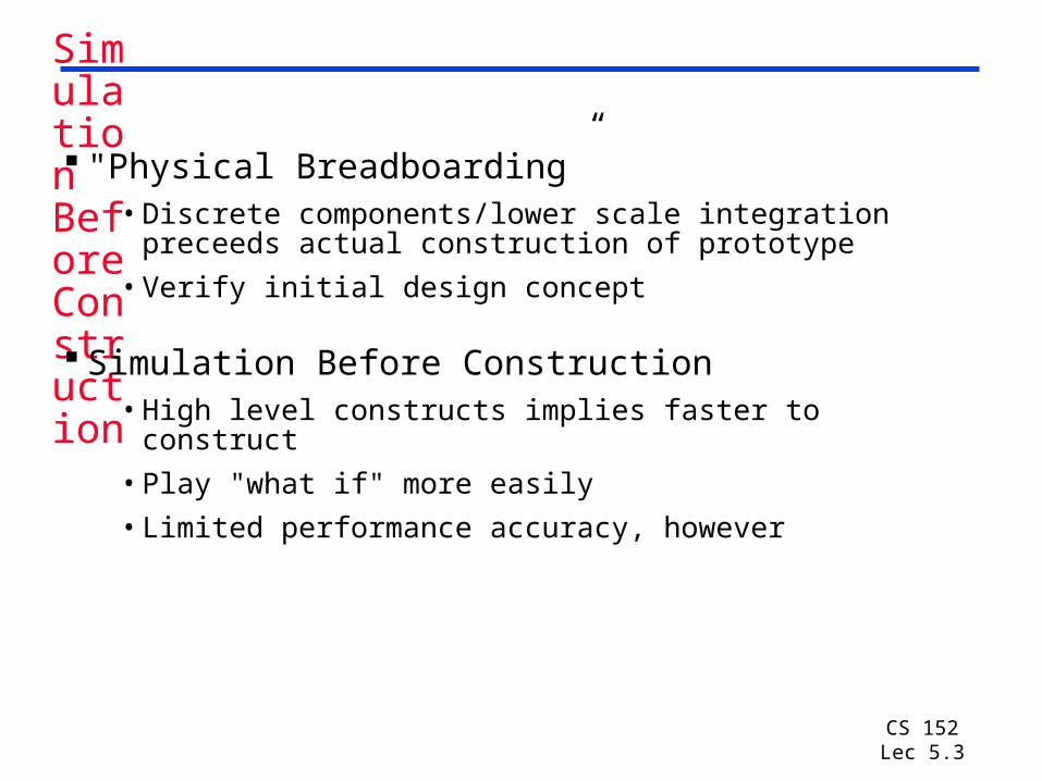
Simulation Before Construction
"Physical Breadboarding”• Discrete components/lower scale integration preceeds
actual construction of prototype
• Verify initial design concept
Simulation Before Construction• High level constructs implies faster to construct
• Play "what if" more easily
• Limited performance accuracy, however
CS 152Lec 5.4
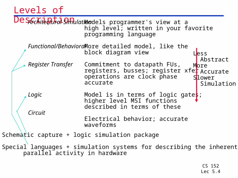
Levels of DescriptionArchitectural Simulation
Functional/Behavioral
Register Transfer
Logic
Circuit
Models programmer's view at ahigh level; written in your favoriteprogramming language
More detailed model, like theblock diagram view
Commitment to datapath FUs,registers, busses; register xferoperations are clock phase accurate
Model is in terms of logic gates;higher level MSI functionsdescribed in terms of these
Electrical behavior; accuratewaveforms
Schematic capture + logic simulation package
Special languages + simulation systems for describing the inherent parallel activity in hardware
Less AbstractMore AccurateSlower Simulation
CS 152Lec 5.5
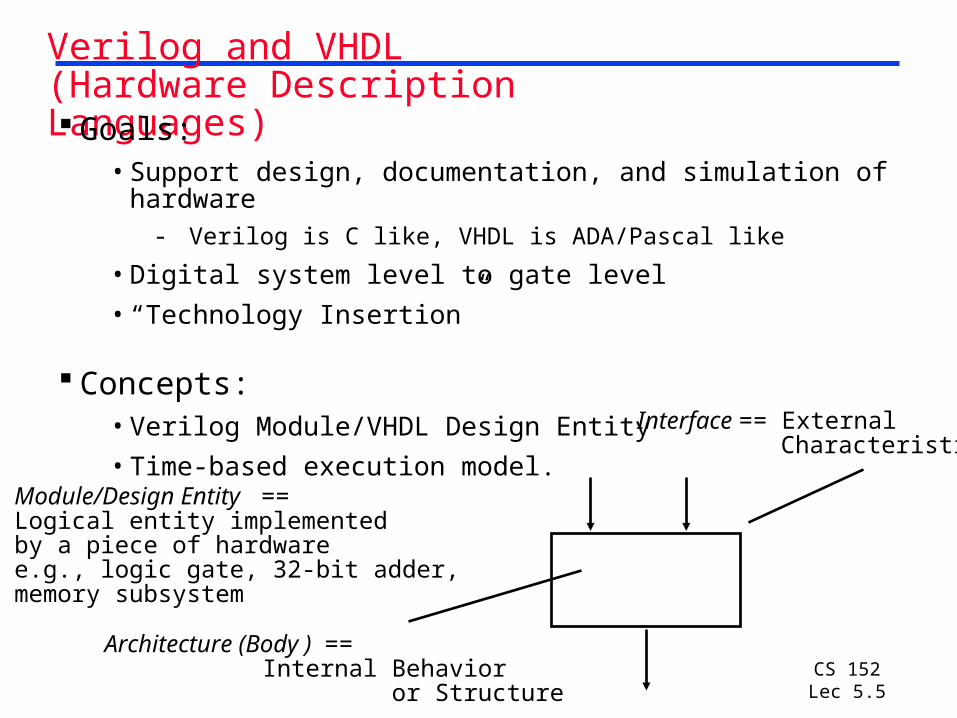
Verilog and VHDL(Hardware Description Languages) Goals:
• Support design, documentation, and simulation of hardware
- Verilog is C like, VHDL is ADA/Pascal like
• Digital system level to gate level
• “Technology Insertion”
Concepts:• Verilog Module/VHDL Design Entity
• Time-based execution model.Module/Design Entity ==Logical entity implementedby a piece of hardwaree.g., logic gate, 32-bit adder, memory subsystem
Interface == External Characteristics
Architecture (Body ) == Internal Behavior or Structure

CS 152Lec 5.6
Very Simple Verilog Model Example
Continuous assignment, combinational logic, behavioral description
Variables can be of type reg, wire, integer, real, event, time
module add2bit (in1, in2, sum);
input in1, in2;
output[1:0] sum;
wire in1, in2;
reg[1:0] sum;
always @(in1 or in2)
begin
sum = in1 + in2;
$display (“The sum of %b and %b is %0d (time = %0d)”, in1, in2, sum, $time);
end
endmodule
Interface: two inputs, one output
Inputs are “wires”/interconnections, output is 2-bit “register”/mem elements
Inputs are monitored, compute sum whenever they changeprint sum and simulation time

CS 152Lec 5.7
Structural Descriptions
Instances of “wired” lower level module within the current module
…
fulladd f1 (cin0, a0, b0, sum0, cout0)
fulladd f2 (cout0, a1, b1, sum1, cout2)
…
f1
a0 b0
cin0
sum0
cout0f2
a1 b1
sum1
cout2

CS 152Lec 5.8
Verilog Operators
Operators borrowed from C programming language
+ - * /
>= < <=
! && ||
== !=
?:
{}
%
=== !==
~ & |
<< >>
Arithmetic
Relational
Logical
Logical equality
Conditional
Concatenate
Modulus
Case equality
Bit-wise
Shift

CS 152Lec 5.9
Control ConstructsIF-THEN-ELSE
if (condition) block; else block;
FORfor (i = 0; i < 4; i = i + 1) block;
WHILE begin
i = 0;while (i < 4) begin statement; statement; i = i + 1;end
end
CASE case (i)
0: statement;1: statement;2: statement;default: $stop;
endcase
Also casex, casez, repeat, forever
CS 152Lec 5.10
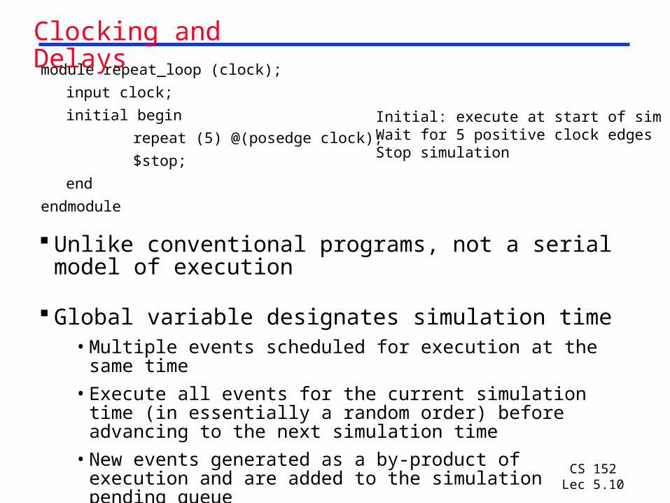
Clocking and Delays
Unlike conventional programs, not a serial model of execution
Global variable designates simulation time• Multiple events scheduled for execution at the same time
• Execute all events for the current simulation time (in essentially a random order) before advancing to the next simulation time
• New events generated as a by-product of execution and are added to the simulation pending queue
module repeat_loop (clock);
input clock;
initial begin
repeat (5) @(posedge clock);
$stop;
end
endmodule
Initial: execute at start of simWait for 5 positive clock edgesStop simulation

CS 152Lec 5.11
Clocking and DelaysSynchronous: #expression – suspend execution for indicated timeAsynchronous: @expression – suspend execution until event occursLevel: wait (expression) – suspend execution until expression true
module time_control;reg[1:0] r;initial #70 $stop;initial begin : b1 //named block b1
#10 r = 1; //wait for 10 time units#20 r = 1; //wait for 20 time units#30 r = 1; //wait for 30 time units
endinitial begin : b2 //named block b2
#5 r = 2; //wait for 5 time units#20 r = 2; //wait for 20 time units#30 r = 2; //wait for 30 time units
endalways @r begin
$display (“r= %0d at time %0d”, r, $time);end
endmodule

CS 152Lec 5.12
Clocking and DelaysSynchronous: #expression – suspend execution for indicated timeAsynchronous: @expression – suspend execution until event occursLevel: wait (expression) – suspend execution until expression true
module event_control;event e1, e2;
initial @e1 begin$display (“I am in the middle.”);-> e2;
endinitial @e2
$display (“I am supposed to execute last.”);
initial begin$display (“I am the first.”);-> e1;
endendmodule

CS 152Lec 5.13
MIPS Arithmetic Instructions
Instruction Example Meaning Commentsadd add $1,$2,$3 $1 = $2 + $3 3 operands; exception possiblesubtract sub $1,$2,$3 $1 = $2 – $3 3 operands; exception possibleadd immediate addi $1,$2,100 $1 = $2 + 100 + constant;
exception possibleadd unsigned addu $1,$2,$3 $1 = $2 + $3 3 operands;
no exceptionssubtract unsigned subu $1,$2,$3 $1 = $2 – $3 3 operands;
no exceptionsadd imm. unsign. addiu $1,$2,100 $1 = $2 + 100 + constant; no exceptionsmultiply mult $2,$3 Hi, Lo = $2 x $3 64-bit signed productmultiply unsigned multu$2,$3 Hi, Lo = $2 x $3 64-bit unsigned productdivide div $2,$3 Lo = $2 ÷ $3, Lo = quotient, Hi = remainder
Hi = $2 mod $3 divide unsigned divu $2,$3 Lo = $2 ÷ $3, Unsigned quotient & remainder
Hi = $2 mod $3Move from Hi mfhi $1 $1 = Hi Used to get copy of HiMove from Lo mflo $1 $1 = Lo Used to get copy of Lo

CS 152Lec 5.14
MULTIPLY (unsigned) Paper and pencil example (unsigned):
Multiplicand 1000 Multiplier 1001 1000 0000
0000 1000
Product 01001000
m bits x n bits = m+n bit product
Binary makes it easy:
• 0 => place 0 ( 0 x multiplicand)
• 1 => place a copy ( 1 x multiplicand)
Four versions of multiply hardware & algorithm:
• Successive refinement

CS 152Lec 5.15
Unsigned Combinational Multiplier
Stage i accumulates A * 2 i if Bi == 1
Q: How much hardware for 32 bit multiplier? Critical path?
B0
A0A1A2A3
A0A1A2A3
A0A1A2A3
A0A1A2A3
B1
B2
B3
P0P1P2P3P4P5P6P7
0 0 0 0

CS 152Lec 5.16
Carry Save Addition of Four Integers
Add Columns first,
then rows!
Can be used to reduce critical path of multiply
Example: 53 bit multiply (for floating point):
• At least 53 levels with naïve technique
• Only 9 with Carry save addition!
Carry Save Adder3=>2
I1 I2
S0S1
I3
Carry Save Adder3=>2
I1 I2
S0S1
I3
Carry Save Adder3=>2
I1 I2
S0S1
I3
0
C2
Carry Save Adder3=>2
I1 I2
S0S1
I3
Carry Save Adder3=>2
I1 I2
S0S1
I3
Carry Save Adder3=>2
I1 I2
S0S1
I3
S0S1S2S3S4
Carry Save Adder3=>2
I1 I2
S0S1
I3
Carry Save Adder3=>2
I1 I2
S0S1
I3
0
Carry Save Adder3=>2
I1 I2
S0S1
I3
B2 A2 C1 B1 A1 C0 B0 A0
D0D1D2

CS 152Lec 5.17
How Does It Work?
At each stage shift A left ( x 2)
Use next bit of B to determine whether to add in shifted multiplicand
Accumulate 2n bit partial product at each stage
B0
A0A1A2A3
A0A1A2A3
A0A1A2A3
A0A1A2A3
B1
B2
B3
P0P1P2P3P4P5P6P7
0 0 0 00 0 0
CS 152Lec 5.18
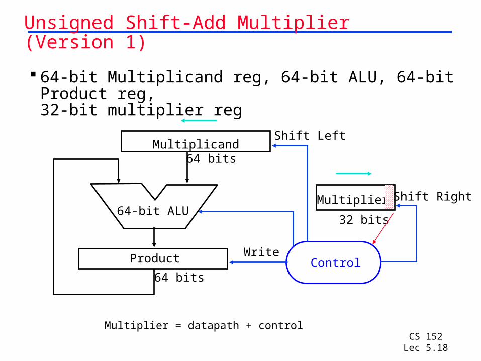
Unsigned Shift-Add Multiplier (Version 1)
64-bit Multiplicand reg, 64-bit ALU, 64-bit Product reg,
32-bit multiplier reg
Product
Multiplier
Multiplicand
64-bit ALU
Shift Left
Shift Right
WriteControl
32 bits
64 bits
64 bits
Multiplier = datapath + control

CS 152Lec 5.19
Multiply Algorithm Version 1
Product MultiplierMultiplicand 0000 0000 00110000 0010
0000 0010 0001 0000 0100
0000 0110 0000 0000 1000
0000 0110
3. Shift the Multiplier register right 1 bit.
Done
Yes: 32 repetitions
2. Shift the Multiplicand register left 1 bit.
No: < 32 repetitions
1. TestMultiplier0
Multiplier0 = 0Multiplier0 = 1
1a. Add multiplicand to product & place the result in Product register
32nd repetition?
Start
CS 152Lec 5.20
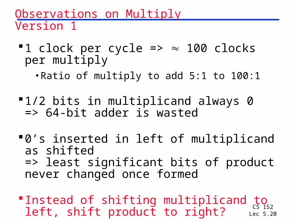
Observations on Multiply Version 1
1 clock per cycle => 100 clocks per multiply
•Ratio of multiply to add 5:1 to 100:1
1/2 bits in multiplicand always 0=> 64-bit adder is wasted
0’s inserted in left of multiplicand as shifted=> least significant bits of product never changed once formed
Instead of shifting multiplicand to left, shift product to right?
CS 152Lec 5.21
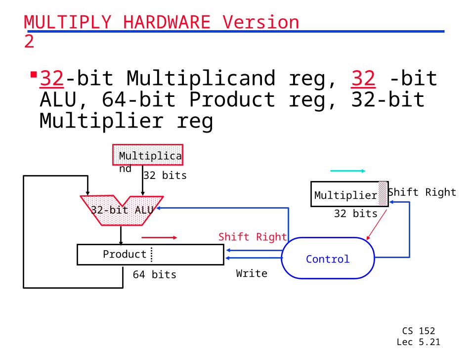
MULTIPLY HARDWARE Version 2
32-bit Multiplicand reg, 32 -bit ALU, 64-bit Product reg, 32-bit Multiplier reg
Product
Multiplier
Multiplicand
32-bit ALU
Shift Right
WriteControl
32 bits
32 bits
64 bits
Shift Right

CS 152Lec 5.22
How to think of this?
B0
A0A1A2A3
A0A1A2A3
A0A1A2A3
A0A1A2A3
B1
B2
B3
P0P1P2P3P4P5P6P7
0 0 0 0
Remember original combinational multiplier:
CS 152Lec 5.23
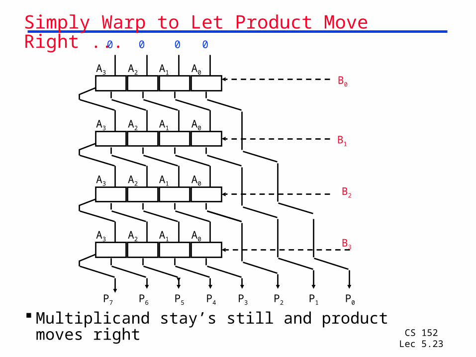
Simply Warp to Let Product Move Right ...
Multiplicand stay’s still and product moves right
B0
B1
B2
B3
P0P1P2P3P4P5P6P7
0 0 0 0
A0A1A2A3
A0A1A2A3
A0A1A2A3
A0A1A2A3

CS 152Lec 5.24
Multiply Algorithm Version 2
3. Shift the Multiplier register right 1 bit.
Done
Yes: 32 repetitions
2. Shift the Product register right 1 bit.
No: < 32 repetitions
1. TestMultiplier0
Multiplier0 = 0Multiplier0 = 1
1a. Add multiplicand to the left half of product & place the result in the left half of Product register
32nd repetition?
Start
0000 0000 0011 00101: 0010 0000 0011 00102: 0001 0000 0011 00103: 0001 0000 0001 00101: 0011 0000 0001 00102: 0001 1000 0001 00103: 0001 1000 0000 00101: 0001 1000 0000 00102: 0000 1100 0000 00103: 0000 1100 0000 00101: 0000 1100 0000 00102: 0000 0110 0000 00103: 0000 0110 0000 0010
0000 0110 0000 0010
Product Multiplier Multiplicand

CS 152Lec 5.25
Still More Wasted Space!
3. Shift the Multiplier register right 1 bit.
Done
Yes: 32 repetitions
2. Shift the Product register right 1 bit.
No: < 32 repetitions
1. TestMultiplier0
Multiplier0 = 0Multiplier0 = 1
1a. Add multiplicand to the left half of product & place the result in the left half of Product register
32nd repetition?
Start
0000 0000 0011 00101: 0010 0000 0011 00102: 0001 0000 0011 00103: 0001 0000 0001 00101: 0011 0000 0001 00102: 0001 1000 0001 00103: 0001 1000 0000 00101: 0001 1000 0000 00102: 0000 1100 0000 00103: 0000 1100 0000 00101: 0000 1100 0000 00102: 0000 0110 0000 00103: 0000 0110 0000 0010
0000 0110 0000 0010
Product Multiplier Multiplicand

CS 152Lec 5.26
Observations on Multiply Version 2
Product register wastes space that exactly matches size of multiplier=> combine Multiplier register and Product register

CS 152Lec 5.27
MULTIPLY HARDWARE Version 3
32-bit Multiplicand reg, 32 -bit ALU, 64-bit Product reg, (0-bit Multiplier reg)
Product (Multiplier)
Multiplicand
32-bit ALU
WriteControl
32 bits
64 bits
Shift Right

CS 152Lec 5.28
Multiply Algorithm Version 3Multiplicand Product
0010 0000 0011
Done
Yes: 32 repetitions
2. Shift the Product register right 1 bit.
No: < 32 repetitions
1. TestProduct0
Product0 = 0Product0 = 1
1a. Add multiplicand to the left half of product & place the result in the left half of Product register
32nd repetition?
Start

CS 152Lec 5.29
Observations on Multiply Version 3 2 steps per bit because Multiplier & Product
combined
MIPS registers Hi/Lo are left/right half of Product
Gives us MIPS instruction MultU
How can you make it faster?
What about signed multiplication?• Easiest solution--make both positive & remember to
comple-ment product if necessary when done (leave out the sign bit, run for 31 steps)
• Apply definition of 2’s complement - Need to sign-extend partial products and subtract at the
end
• Booth’s Algorithm is elegant way to multiply signed numbers using same hardware as before and save cycles
- Can handle multiple bits at a time

CS 152Lec 5.30
Motivation for Booth’s Algorithm Example 2 x 6 = 0010 x 0110:
0010 x 0110 + 0000 shift (0 in multiplier) + 0010 add (1 in multiplier)
+ 0010 add (1 in multiplier) + 0000 shift (0 in multiplier)
00001100
ALU with add or subtract gets same result in more than one way: 6 = – 2 + 8
0110 = – 00010 + 01000 = 11110 + 01000
For example
0010 x 0110 0000 shift (0 in multiplier)– 0010 sub(first 1 in multpl.) .
0000 shift (mid string of 1s) . + 0010 add (prior step had last 1) 00001100

CS 152Lec 5.31
Booth’s Algorithm
Current Bit Bit to the Right Explanation Example Op
1 0 Begins run of 1s 0001111000 sub
1 1 Middle of run of 1s 0001111000none
0 1 End of run of 1s 0001111000 add
0 0 Middle of run of 0s 0001111000none
Originally for Speed (when shift was faster than add)
Replace a string of 1s in multiplier with an initial subtract when we first see a one and then later add for the bit after the last one
0 1 1 1 1 0beginning of runend of run
middle of run
–1+ 1000001111

CS 152Lec 5.32
Booth’s Example (2 x 7)
1a. P = P - m 1110 + 11101110 0111 0
shift P (sign ext)
1b. 0010 1111 0011 1 11 -> nop, shift
2. 0010 1111 1001 111 -> nop, shift
3. 0010 1111 1100 101 -> add
4a. 0010 + 0010
0001 1100 1 shift
4b. 0010 0000 1110 0 done
Operation Multiplicand Product next?
0. initial value 0010 0000 0111 010 -> sub

CS 152Lec 5.33
Booth’s Example (2 x -3)
1a. P = P - m 1110 +11101110 1101 0 shift P (sign
ext)
1b. 0010 1111 0110 1 01 -> add +0010
2a. 0001 0110 1 shift P
2b. 0010 0000 1011 0 10 -> sub +1110
3a. 0010 1110 1011 0 shift
3b. 0010 1111 0101 1 11 -> nop
4a 1111 0101 1 shift
4b. 0010 1111 1010 1 done
Operation Multiplicand Product next?
0. initial value 0010 0000 1101 0 10 -> sub

CS 152Lec 5.34
Current Bit to the Explanation Example RecodeBits Right
0 0 0 Middle of zeros 00 00 00 00 00 00 (0)
0 1 0 Single one 00 00 00 01 00 01 (1)
1 0 0 Begins run of 1s 00 01 11 10 00 10 (-2)
1 1 0 Begins run of 1s 00 01 11 11 00 01 (-1)
0 0 1 Ends run of 1s 00 00 11 11 00 01 (1)
0 1 1 Ends run of 1s 00 01 11 11 00 10 (2)
1 0 1 Isolated 0 00 11 10 11 00 01 (-1)
1 1 1 Middle of run 00 11 11 11 00 00 (0)
Radix-4 Modified Booth’sMultiple Representations
Once admit new symbols (i.e. 1), can have multiple representations of a number:

CS 152Lec 5.35
MIPS Logical InstructionsInstruction Example Meaning Commentand and $1,$2,$3 $1 = $2 & $3 3 reg. operands; Logical ANDor or $1,$2,$3 $1 = $2 | $3 3 reg. operands; Logical ORxor xor $1,$2,$3 $1 = $2 $3 3 reg. operands; Logical XORnor nor $1,$2,$3 $1 = ~($2 | $3) 3 reg. operands; Logical NORand immediate andi $1,$2,10 $1 = $2 & 10 Logical AND reg, constantor immediate ori $1,$2,10 $1 = $2 | 10 Logical OR reg, constantxor immediate xori $1, $2,10 $1 = ~$2 &~10 Logical XOR reg, constantshift left logical sll $1,$2,10 $1 = $2 << 10 Shift left by constantshift right logical srl $1,$2,10 $1 = $2 >> 10 Shift right by constantshift right arithm. sra $1,$2,10 $1 = $2 >> 10 Shift right (sign extend) shift left logical sllv $1,$2,$3 $1 = $2 << $3 Shift left by variableshift right logical srlv $1,$2, $3 $1 = $2 >> $3 Shift right by variableshift right arithm. srav $1,$2, $3 $1 = $2 >> $3 Shift right arith. by variable

CS 152Lec 5.36
Shifters
Two kinds: logical-- value shifted in is always "0"
arithmetic-- on right shifts, sign extend
msb lsb"0" "0"
msb lsb "0"
Note: these are single bit shifts. A given instruction might request 0 to 32 bits to be shifted!

CS 152Lec 5.37
Combinational Shifter from MUXes
What comes in the MSBs?
How many levels for 32-bit shifter?
What if we use 4-1 Muxes ?
1 0sel
A B
D
Basic Building Block
8-bit right shifter
1 0 1 0 1 0 1 0 1 0 1 0 1 0 1 0
1 0 1 0 1 0 1 0 1 0 1 0 1 0 1 0
1 0 1 0 1 0 1 0 1 0 1 0 1 0 1 0
S2 S1 S0A0A1A2A3A4A5A6A7
R0R1R2R3R4R5R6R7

CS 152Lec 5.38
General Shift Right Scheme Using 16 bit Example
If added Right-to-left connections couldsupport Rotate (not in MIPS but found in ISAs)
S 0 (0,1)
S 1(0, 2)
S 3(0, 8)
S 2(0, 4)

CS 152Lec 5.39
Funnel Shifter
XY
R Shift A by i bits (sa= shift right amount)
Logical: Y = 0, X=A, sa=i
Arithmetic? Y = _, X=_, sa=_
Rotate? Y = _, X=_, sa=_
Left shifts? Y = _, X=_, sa=_
Instead Extract 32 bits of 64
Shift Right
Shift Right
32 32
32
Y X
R
CS 152Lec 5.40
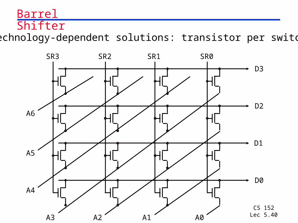
Barrel Shifter
Technology-dependent solutions: transistor per switch
D3
D2
D1
D0
A6
A5
A4
A3 A2 A1 A0
SR0SR1SR2SR3
CS 152Lec 5.41
Summary Introduction to Verilog (more in discussion sections!)
• High level language to describe hardware- Module describes behavior or structure
- Behavior can be higher level, e.g., x = boolean_expression(A,B,C,D);
• Time units as an explicitly managed concept within description
• Can activate modules when inputs change, not specifically invoked
• Inherently parallel, need to understand implications of event scheduling
Multiply: successive refinement to see final design
• 32-bit Adder, 64-bit shift register, 32-bit Multiplicand Register
• Booth’s algorithm to handle signed multiplies
• There are algorithms that calculate many bits of multiply per cycle (see exercises 4.36 to 4.39 in COD)
Shifter: successive refinement of 1/bit at a time shift register to barrel shifter