cs-184: computer graphics - university of california,...
TRANSCRIPT
CS-184: Computer Graphics
Lecture 8: ProjectionManeesh Agrawala
University of California, Berkeley
Slides based on those of James O’Brien and Stebve Marschner
Announcements
Assignments 1 and 2 results posted
Assignment 4: due Fri Oct 8 by 11pm
4
5
Today
History and Definitions
Rendering with Projections• Windows and viewports• Orthographic projection• Perspective projection
History and Definitions
History of ProjectionAncient times: Greeks wrote about laws of perspective
Renaissance: Perspective is adopted by artists
Duccio c. 1308
7
History of ProjectionLater Renaissance: Perspective formalized precisely
da Vinci c. 1498
8
Plane Projection in Drawing
9
Trace rays from eye through image plane into scene

Plane Projection in Drawing[C
arlb
om &
Pac
iore
k 78
]
10
Classical ProjectionsEmphasis on cube-like objects
• traditional in mechanical and architectural drawing
Planar Geometric Projections
Parallel
Oblique
MultiviewOrthographic
Perspective
One-point Two-point Three-pointOrthographic
Axonometric [aft
er C
arlb
om &
Pac
iore
k 78
]
11
12
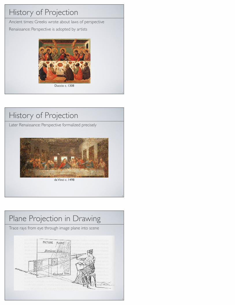
Linear Projection
Orthographic Perspective
13
Linear Projection
Orthographic Perspective
14
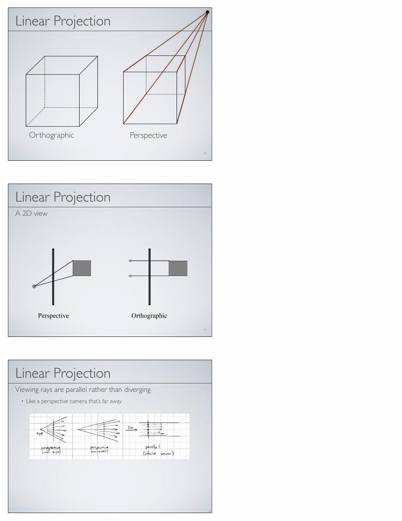
Linear ProjectionA 2D view
OrthographicPerspective
Linear ProjectionViewing rays are parallel rather than diverging
• Like a perspective camera that’s far away
15

16
OrthographicPerspective
Note how different things can be seen
Parallel lines “meet” at infinity
Linear ProjectionA 2D view
Orthographic View
• Projection plane parallel to a coordinate plane• Projection direction perpendicular to projection plane
17
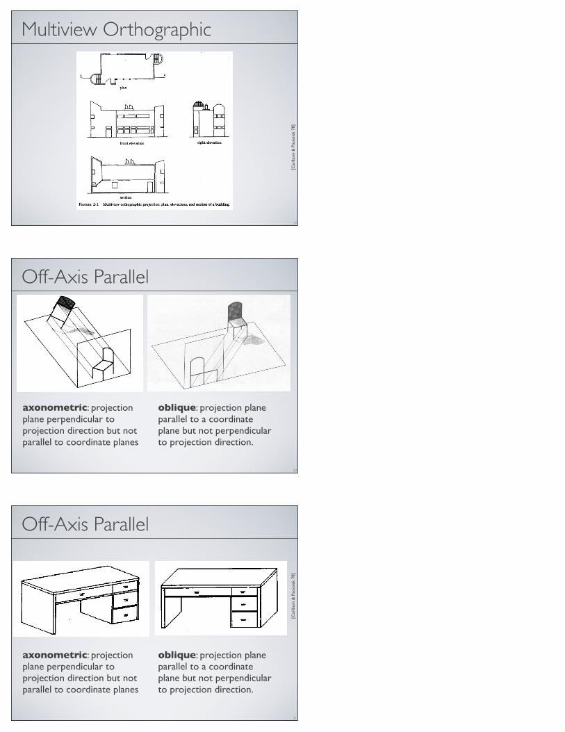
Multiview Orthographic
• Projection plane parallel to a coordinate plane• Projection direction perpendicular to projection plane
[Car
lbom
& P
acio
rek
78]
18
Multiview Orthographic
[Car
lbom
& P
acio
rek
78]
19
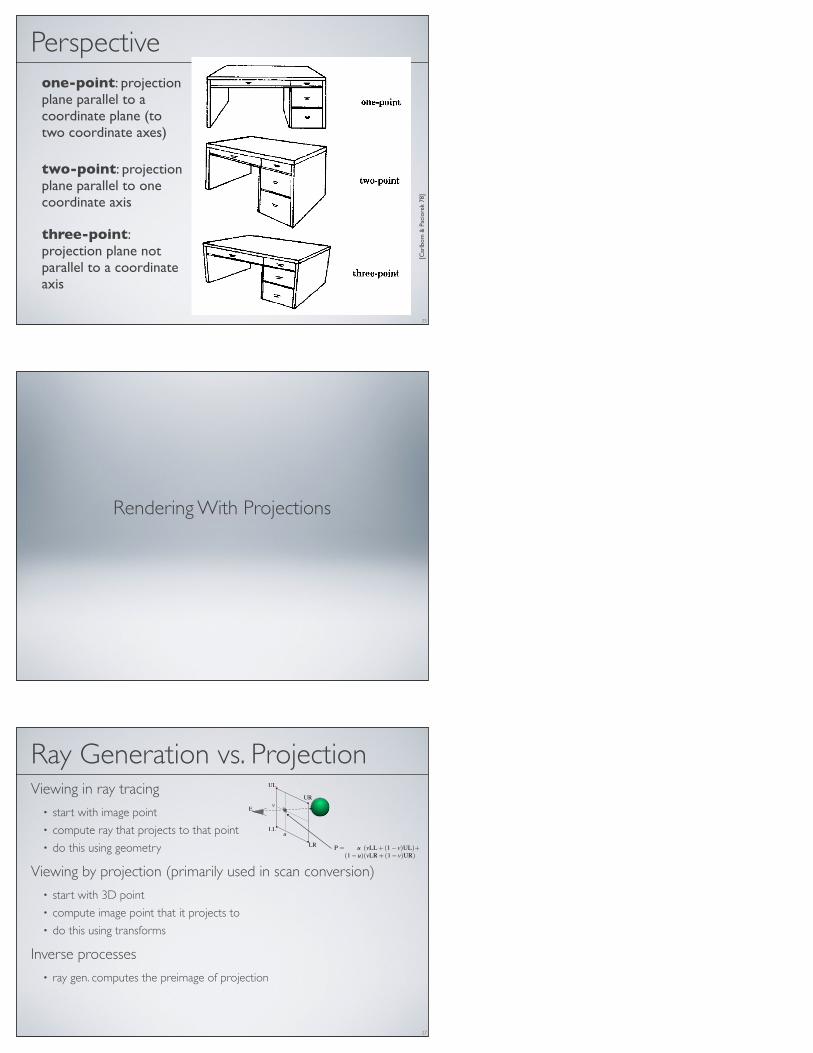
Off-Axis Parallel
axonometric: projection plane perpendicular to projection direction but not parallel to coordinate planes
oblique: projection plane parallel to a coordinate plane but not perpendicular to projection direction.
20
Off-Axis Parallel
[Car
lbom
& P
acio
rek
78]
21
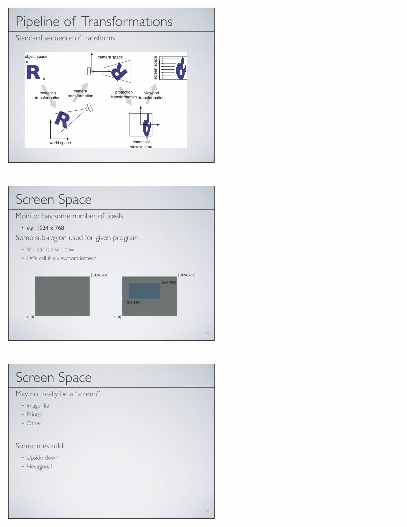
axonometric: projection plane perpendicular to projection direction but not parallel to coordinate planes
oblique: projection plane parallel to a coordinate plane but not perpendicular to projection direction.

22
Perspective Projection
Vanishing points• Depend on the scene• Not intrinsic to camera
“One point perspective”
23
Perspective Projection
Vanishing points• Depend on the scene• Nor intrinsic to camera
“Two point perspective”
24
Perspective Projection
Vanishing points• Depend on the scene• Not intrinsic to camera
“Three point perspective”
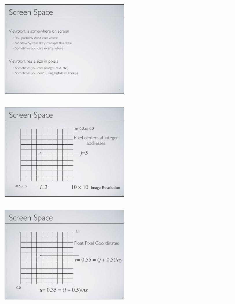
Perspectiveone-point: projection plane parallel to a coordinate plane (to two coordinate axes)
two-point: projection plane parallel to one coordinate axis
three-point: projection plane not parallel to a coordinate axis
[Car
lbom
& P
acio
rek
78]
25
Rendering With Projections
Ray Generation vs. ProjectionViewing in ray tracing
• start with image point• compute ray that projects to that point• do this using geometry
Viewing by projection (primarily used in scan conversion)• start with 3D point• compute image point that it projects to• do this using transforms
Inverse processes• ray gen. computes the preimage of projection
27
LL
LR
UR
UL
E
P
u
v
P= u (vLL+(1− v)UL)+(1−u)(vLR+(1− v)UR)
Pipeline of TransformationsStandard sequence of transforms
28
!
!
!
!
!
!
!
!
7.1. Viewing Transformations 147
object space
world space
camera space
canonicalview volume
scre
en
sp
ace
modelingtransformation
viewporttransformation
projectiontransformation
cameratransformation
Figure 7.2. The sequence of spaces and transformations that gets objects from their
original coordinates into screen space.
space) to camera coordinates or places them in camera space. The projection
transformation moves points from camera space to the canonical view volume.
Finally, the viewport transformation maps the canonical view volume to screen Other names: camera
space is also “eye space”
and the camera
transformation is
sometimes the “viewing
transformation;” the
canonical view volume is
also “clip space” or
“normalized device
coordinates;” screen space
is also “pixel coordinates.”
space.
Each of these transformations is individually quite simple. We’ll discuss them
in detail for the orthographic case beginning with the viewport transformation,
then cover the changes required to support perspective projection.
7.1.1 The Viewport Transformation
We begin with a problemwhose solution will be reused for any viewing condition.
We assume that the geometry we want to view is in the canonical view volume The word “canonical” crops
up again—it means
something arbitrarily
chosen for convenience.
For instance, the unit circle
could be called the
“canonical circle.”
and we wish to view it with an orthographic camera looking in the !z direction.The canonical view volume is the cube containing all 3D points whose Cartesian
coordinates are between !1 and +1—that is, (x, y, z) " [!1, 1]3 (Figure 7.3).We project x = !1 to the left side of the screen, x = +1 to the right side of thescreen, y = !1 to the bottom of the screen, and y = +1 to the top of the screen.
Recall the conventions for pixel coordinates fromChapter 3: each pixel “owns”
a unit square centered at integer coordinates; the image boundaries have a half-
unit overshoot from the pixel centers; and the smallest pixel center coordinates
29
Screen SpaceMonitor has some number of pixels
• e.g. 1024 x 768
Some sub-region used for given program• You call it a window• Let’s call it a viewport instead
[0,0]
[1024,768]
[60,350]
[690,705]
[0,0]
[1024,768]
30
Screen SpaceMay not really be a “screen”
• Image file• Printer• Other
Sometimes odd• Upside down• Hexagonal
31
Screen Space
Viewport is somewhere on screen• You probably don’t care where• Window System likely manages this detail• Sometimes you care exactly where
Viewport has a size in pixels• Sometimes you care (images, text, etc.)• Sometimes you don’t (using high-level library)
Screen Space
32
Pixel centers at integeraddresses
i=3
j=5
10 × 10 Image Resolution-0.5,-0.5
nx-0.5,ny-0.5
Screen Space
33
Float Pixel Coordinates
u= 0.35 = (i + 0.5)/nx 0,0
1,1
v= 0.55 = (j + 0.5)/ny
34
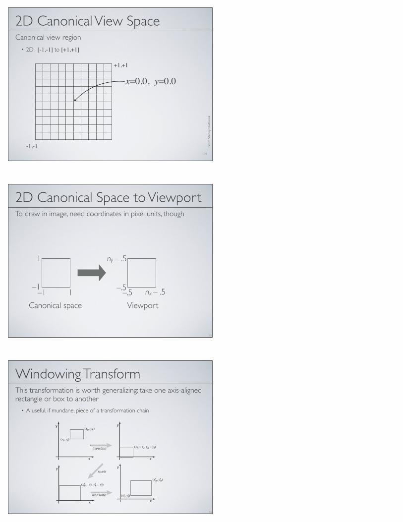
2D Canonical View SpaceCanonical view region
• 2D: [-1,-1] to [+1,+1]
From
Shi
rley
text
book
.
-1,-1
+1,+1
x=0.0, y=0.0
2D Canonical Space to ViewportTo draw in image, need coordinates in pixel units, though
35
–1–1
1
1 –.5–.5
ny – .5
nx – .5
Canonical space Viewport
Windowing TransformThis transformation is worth generalizing: take one axis-aligned rectangle or box to another
• A useful, if mundane, piece of a transformation chain
36
!
!
!
!
!
!
!
!
6.3. Translation 135
In 3D, the same technique works: we can add a fourth coordinate, a homoge-
neous coordinate, and then we have translations:
!
"
"
#
1 0 0 xt
0 1 0 yt
0 0 1 zt
0 0 0 1
$
%
%
&
!
"
"
#
xyz1
$
%
%
&
=
!
"
"
#
x + xt
y + yt
z + zt
1
$
%
%
&
.
Again, for a vector, the fourth coordinate is zero and the vector is thus unaffected
by translations.
Example 8 (Windowing Transformations) Often in graphics we need to create
a transform matrix that takes points in the rectangle [xl, xh] ! [yl, yh] to therectangle [x!
l, x!h] ! [y!
l, y!h]. This can be accomplished with a single scale and
translate in sequence. However, it is more intuitive to create the transform from a
sequence of three operations (Figure 6.16):
1. Move the point (xl, yl) to the origin.
2. Scale the rectangle to be the same size as the target rectangle.
3. Move the origin to point (x!l, y
!l).
(xl, yl)
(x!l, y!l)
(xh, yh)
(x!h, y!h)
(xh – xl, yh – yl)
(x!h – x!l, y!h – y!l)
Figure 6.16. To take one rectangle (window) to the other, we first shift the lower-left cornerto the origin, then scale it to the new size, and then move the origin to the lower-left cornerof the target rectangle.

Windowing Transform
37
!
!
!
!
!
!
!
!
136 6. Transformation Matrices
Remembering that the right-hand matrix is applied first, we can write
window = translate (x!l, y
!l) scale
!
x!h ! x!
l
xh ! xl,y!
h ! y!l
yh ! yl
"
translate (!xl,!yl)
=
#
$
%
1 0 x!l
0 1 y!l
0 0 1
&
'
(
#
$
$
%
x!
h"x!
l
xh"xl0 0
0 y!
h"y!
l
yh"yl0
0 0 1
&
'
'
(
#
$
%
1 0 !xl
0 1 !yl
0 0 1
&
'
(
=
#
$
$
%
x!
h"x!
l
xh"xl0 x!
lxh"x!
hxl
xh"xl
0 y!
h"y!
l
yh"yl
y!
lyh"y!
hyl
yh"yl
0 0 1
&
'
'
(
.
(6.6)
It is perhaps not surprising to some readers that the resulting matrix has the form
it does, but the constructive process with the three matrices leaves no doubt as to
the correctness of the result.
An exactly analogous construction can be used to define a 3D windowing
transformation, which maps the box [xl, xh]"[yl, yh]"[zl, zh] to the box [x!l, x
!h]"
[y!l, y
!h] " [z!l, z
!h]
#
$
$
$
$
$
%
x!
h"x!
l
xh"xl0 0 x!
lxh"x!
hxl
xh"xl
0 y!
h"y!
l
yh"yl0 y!
lyh"y!
hyl
yh"yl
0 0 z!
h"z!
l
zh"zl
z!
lzh"z!
hzl
zh"zl
0 0 0 1
&
'
'
'
'
'
(
. (6.7)
It is interesting to note that if we multiply an arbitrary matrix composed of
scales, shears and rotations with a simple translation (translation comes second),
we get#
$
$
%
1 0 0 xt
0 1 0 yt
0 0 1 zt
0 0 0 1
&
'
'
(
#
$
$
%
a11 a12 a13 0a21 a22 a23 0a31 a32 a33 00 0 0 1
&
'
'
(
=
#
$
$
%
a11 a12 a13 xt
a21 a22 a23 yt
a31 a32 a33 zt
0 0 0 1
&
'
'
(
.
Thus we can look at any matrix and think of it as a scaling/rotation part and a
translation part because the components are nicely separated from each other.
An important class of transforms are rigid-body transforms. These are com-
posed only of translations and rotations, so they have no stretching or shrinking
of the objects. Such transforms will have a pure rotation for the aij above.
!
!
!
!
!
!
!
!
6.3. Translation 135
In 3D, the same technique works: we can add a fourth coordinate, a homoge-
neous coordinate, and then we have translations:
!
"
"
#
1 0 0 xt
0 1 0 yt
0 0 1 zt
0 0 0 1
$
%
%
&
!
"
"
#
xyz1
$
%
%
&
=
!
"
"
#
x + xt
y + yt
z + zt
1
$
%
%
&
.
Again, for a vector, the fourth coordinate is zero and the vector is thus unaffected
by translations.
Example 8 (Windowing Transformations) Often in graphics we need to create
a transform matrix that takes points in the rectangle [xl, xh] ! [yl, yh] to therectangle [x!
l, x!h] ! [y!
l, y!h]. This can be accomplished with a single scale and
translate in sequence. However, it is more intuitive to create the transform from a
sequence of three operations (Figure 6.16):
1. Move the point (xl, yl) to the origin.
2. Scale the rectangle to be the same size as the target rectangle.
3. Move the origin to point (x!l, y
!l).
(xl, yl)
(x!l, y!l)
(xh, yh)
(x!h, y!h)
(xh – xl, yh – yl)
(x!h – x!l, y!h – y!l)
Figure 6.16. To take one rectangle (window) to the other, we first shift the lower-left cornerto the origin, then scale it to the new size, and then move the origin to the lower-left cornerof the target rectangle.
!
!
!
!
!
!
!
!
136 6. Transformation Matrices
Remembering that the right-hand matrix is applied first, we can write
window = translate (x!l, y
!l) scale
!
x!h ! x!
l
xh ! xl,y!
h ! y!l
yh ! yl
"
translate (!xl,!yl)
=
#
$
%
1 0 x!l
0 1 y!l
0 0 1
&
'
(
#
$
$
%
x!
h"x!
l
xh"xl0 0
0 y!
h"y!
l
yh"yl0
0 0 1
&
'
'
(
#
$
%
1 0 !xl
0 1 !yl
0 0 1
&
'
(
=
#
$
$
%
x!
h"x!
l
xh"xl0 x!
lxh"x!
hxl
xh"xl
0 y!
h"y!
l
yh"yl
y!
lyh"y!
hyl
yh"yl
0 0 1
&
'
'
(
.
(6.6)
It is perhaps not surprising to some readers that the resulting matrix has the form
it does, but the constructive process with the three matrices leaves no doubt as to
the correctness of the result.
An exactly analogous construction can be used to define a 3D windowing
transformation, which maps the box [xl, xh]"[yl, yh]"[zl, zh] to the box [x!l, x
!h]"
[y!l, y
!h] " [z!l, z
!h]
#
$
$
$
$
$
%
x!
h"x!
l
xh"xl0 0 x!
lxh"x!
hxl
xh"xl
0 y!
h"y!
l
yh"yl0 y!
lyh"y!
hyl
yh"yl
0 0 z!
h"z!
l
zh"zl
z!
lzh"z!
hzl
zh"zl
0 0 0 1
&
'
'
'
'
'
(
. (6.7)
It is interesting to note that if we multiply an arbitrary matrix composed of
scales, shears and rotations with a simple translation (translation comes second),
we get#
$
$
%
1 0 0 xt
0 1 0 yt
0 0 1 zt
0 0 0 1
&
'
'
(
#
$
$
%
a11 a12 a13 0a21 a22 a23 0a31 a32 a33 00 0 0 1
&
'
'
(
=
#
$
$
%
a11 a12 a13 xt
a21 a22 a23 yt
a31 a32 a33 zt
0 0 0 1
&
'
'
(
.
Thus we can look at any matrix and think of it as a scaling/rotation part and a
translation part because the components are nicely separated from each other.
An important class of transforms are rigid-body transforms. These are com-
posed only of translations and rotations, so they have no stretching or shrinking
of the objects. Such transforms will have a pure rotation for the aij above.
!
!
!
!
!
!
!
!
136 6. Transformation Matrices
Remembering that the right-hand matrix is applied first, we can write
window = translate (x!l, y
!l) scale
!
x!h ! x!
l
xh ! xl,y!
h ! y!l
yh ! yl
"
translate (!xl,!yl)
=
#
$
%
1 0 x!l
0 1 y!l
0 0 1
&
'
(
#
$
$
%
x!
h"x!
l
xh"xl0 0
0 y!
h"y!
l
yh"yl0
0 0 1
&
'
'
(
#
$
%
1 0 !xl
0 1 !yl
0 0 1
&
'
(
=
#
$
$
%
x!
h"x!
l
xh"xl0 x!
lxh"x!
hxl
xh"xl
0 y!
h"y!
l
yh"yl
y!
lyh"y!
hyl
yh"yl
0 0 1
&
'
'
(
.
(6.6)
It is perhaps not surprising to some readers that the resulting matrix has the form
it does, but the constructive process with the three matrices leaves no doubt as to
the correctness of the result.
An exactly analogous construction can be used to define a 3D windowing
transformation, which maps the box [xl, xh]"[yl, yh]"[zl, zh] to the box [x!l, x
!h]"
[y!l, y
!h] " [z!l, z
!h]
#
$
$
$
$
$
%
x!
h"x!
l
xh"xl0 0 x!
lxh"x!
hxl
xh"xl
0 y!
h"y!
l
yh"yl0 y!
lyh"y!
hyl
yh"yl
0 0 z!
h"z!
l
zh"zl
z!
lzh"z!
hzl
zh"zl
0 0 0 1
&
'
'
'
'
'
(
. (6.7)
It is interesting to note that if we multiply an arbitrary matrix composed of
scales, shears and rotations with a simple translation (translation comes second),
we get#
$
$
%
1 0 0 xt
0 1 0 yt
0 0 1 zt
0 0 0 1
&
'
'
(
#
$
$
%
a11 a12 a13 0a21 a22 a23 0a31 a32 a33 00 0 0 1
&
'
'
(
=
#
$
$
%
a11 a12 a13 xt
a21 a22 a23 yt
a31 a32 a33 zt
0 0 0 1
&
'
'
(
.
Thus we can look at any matrix and think of it as a scaling/rotation part and a
translation part because the components are nicely separated from each other.
An important class of transforms are rigid-body transforms. These are com-
posed only of translations and rotations, so they have no stretching or shrinking
of the objects. Such transforms will have a pure rotation for the aij above.
=
xscreen
yscreen
1
=
nx2 0 nx−1
2
0 ny
2ny−1
2
0 0 1
xcanonical
ycanonical
1
2D Viewport Transformation
38
–1–1
1
1 –.5–.5
ny – .5
nx – .5
-
Add minus sign if necessary to invert y
Canonical space Viewport
3D Canonical View Volume
39
[1,1,1] [-1,-1,-1]
-Zviewpoint
x
y
z
–1–1
1
1
2D Canonical view space3D Canonical view volume
[-1,-1,-1]
[1,1,1]
x
y
-z x
y

3D Canonical to 2D Canonical
to implement basic orthographic projection , just toss out z:
40
xcanonical 2D
ycanonical 2D1
=
1 0 0 00 1 0 00 0 0 1
xcanonical 3D
ycanonical 3Dzcanonical 3D
1
–1–1
1
1
[-1,-1,-1]
[1,1,1]
x
y
-z x
y
3D Canonical view volume 2D Canonical view space
3D Canonical to Viewport
41
[-1,-1,-1]
[1,1,1]
x
y
-z
3D Canonical–1
–1
1
1x
y
2D Canonical–.5
–.5
ny – .5
nx – .5Viewport
xscreen
yscreen1
=
nx2 0 nx−1
2
0 ny
2ny−1
2
0 0 1
1 0 0 00 1 0 00 0 0 1
xcanonical 3D
ycanonical 3Dzcanonical 3D
1
3D Canonical to Viewport
42
xscreen
yscreen1
=
nx2 0 nx−1
2
0 ny
2ny−1
2
0 0 1
1 0 0 00 1 0 00 0 0 1
xcanonical 3D
ycanonical 3Dzcanonical 3D
1
nx2 0 0 nx−1
2
0 ny
2 0 ny−12
0 0 0 1
Viewport transform dropping z
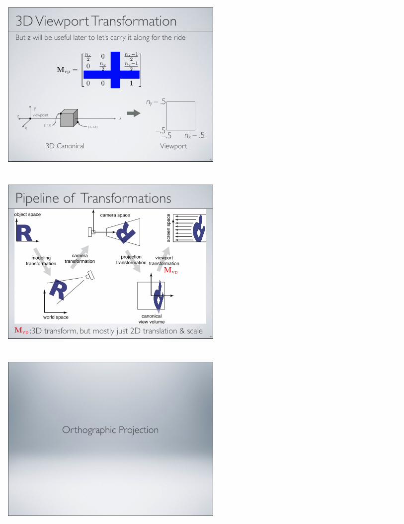
3D Viewport TransformationBut z will be useful later to let’s carry it along for the ride
43
Mvp =
nx2 0 0 nx−1
2
0 ny
2 0 ny−12
0 0 1 00 0 0 1
[1,1,1] [-1,-1,-1]
-Zviewpoint
x
y
z
–.5–.5
ny – .5
nx – .53D Canonical Viewport
Pipeline of Transformations
44
!
!
!
!
!
!
!
!
7.1. Viewing Transformations 147
object space
world space
camera space
canonicalview volume
scre
en
sp
ace
modelingtransformation
viewporttransformation
projectiontransformation
cameratransformation
Figure 7.2. The sequence of spaces and transformations that gets objects from their
original coordinates into screen space.
space) to camera coordinates or places them in camera space. The projection
transformation moves points from camera space to the canonical view volume.
Finally, the viewport transformation maps the canonical view volume to screen Other names: camera
space is also “eye space”
and the camera
transformation is
sometimes the “viewing
transformation;” the
canonical view volume is
also “clip space” or
“normalized device
coordinates;” screen space
is also “pixel coordinates.”
space.
Each of these transformations is individually quite simple. We’ll discuss them
in detail for the orthographic case beginning with the viewport transformation,
then cover the changes required to support perspective projection.
7.1.1 The Viewport Transformation
We begin with a problemwhose solution will be reused for any viewing condition.
We assume that the geometry we want to view is in the canonical view volume The word “canonical” crops
up again—it means
something arbitrarily
chosen for convenience.
For instance, the unit circle
could be called the
“canonical circle.”
and we wish to view it with an orthographic camera looking in the !z direction.The canonical view volume is the cube containing all 3D points whose Cartesian
coordinates are between !1 and +1—that is, (x, y, z) " [!1, 1]3 (Figure 7.3).We project x = !1 to the left side of the screen, x = +1 to the right side of thescreen, y = !1 to the bottom of the screen, and y = +1 to the top of the screen.
Recall the conventions for pixel coordinates fromChapter 3: each pixel “owns”
a unit square centered at integer coordinates; the image boundaries have a half-
unit overshoot from the pixel centers; and the smallest pixel center coordinates
Mvp
:3D transform, but mostly just 2D translation & scaleMvp
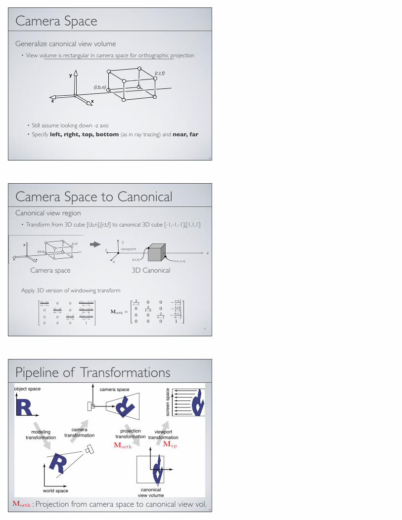
Orthographic Projection
Camera Space
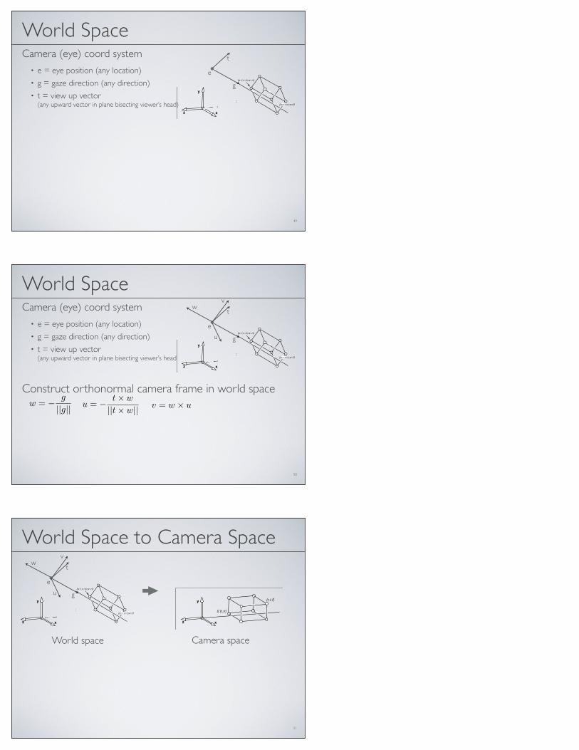
Generalize canonical view volume• View volume is rectangular in camera space for orthographic projection
• Still assume looking down -z axis• Specify left, right, top, bottom (as in ray tracing) and near, far
46
!
!
!
!
!
!
!
!
7.1. Viewing Transformations 149
Figure 7.5. The orthographic view volume is along the negative z-axis, so f is a morenegative number than n, thus n > f.
the bounding planes as follows:
x = l ! left plane,
x = r ! right plane,
y = b ! bottom plane,
y = t ! top plane,
z = n ! near plane,
z = f ! far plane.
That vocabulary assumes a viewer who is looking along the minus z-axis with
Figure 7.4. The ortho-graphic view volume.
his head pointing in the y-direction. 1 This implies that n > f , which may beunintuitive, but if you assume the entire orthographic view volume has negative zvalues then the z = n “near” plane is closer to the viewer if and only if n > f ;here f is a smaller number than n, i.e., a negative number of larger absolute valuethan n.
This concept is shown in Figure 7.5. The transform from orthographic view
volume to the canonical view volume is another windowing transform, so we can
simply substitute the bounds of the orthographic and canonical view volumes into
Equation 6.7 to obtain the matrix for this transformation: n and f appear in whatmight seem like reverseorder because n " f ,rather than f " n, is apositive number.
Morth =
!
"
"
#
2r!l 0 0 " r+l
r!l
0 2
t!b0 " t+b
t!b
0 0 2n!f
" n+tn!f
0 0 0 1
$
%
%
&
(7.3)
1Most programmers find it intuitive to have the x-axis pointing right and the y-axis pointing up. Ina right-handed coordinate system, this implies that we are looking in the !z direction. Some systemsuse a left-handed coordinate system for viewing so that the gaze direction is along +z. Which is bestis a matter of taste, and this text assumes a right-handed coordinate system. A reference that argues
for the left-handed system instead is given in the notes at the end of the chapter.
47
Camera Space to CanonicalCanonical view region
• Transform from 3D cube [l,b,n],[r,t,f] to canonical 3D cube [-1,-1,-1],[1,1,1]
[1,1,1] [-1,-1,-1]
-Zviewpoint
x
y
z
3D Canonical
!
!
!
!
!
!
!
!
7.1. Viewing Transformations 149
Figure 7.5. The orthographic view volume is along the negative z-axis, so f is a morenegative number than n, thus n > f.
the bounding planes as follows:
x = l ! left plane,
x = r ! right plane,
y = b ! bottom plane,
y = t ! top plane,
z = n ! near plane,
z = f ! far plane.
That vocabulary assumes a viewer who is looking along the minus z-axis with
Figure 7.4. The ortho-graphic view volume.
his head pointing in the y-direction. 1 This implies that n > f , which may beunintuitive, but if you assume the entire orthographic view volume has negative zvalues then the z = n “near” plane is closer to the viewer if and only if n > f ;here f is a smaller number than n, i.e., a negative number of larger absolute valuethan n.
This concept is shown in Figure 7.5. The transform from orthographic view
volume to the canonical view volume is another windowing transform, so we can
simply substitute the bounds of the orthographic and canonical view volumes into
Equation 6.7 to obtain the matrix for this transformation: n and f appear in whatmight seem like reverseorder because n " f ,rather than f " n, is apositive number.
Morth =
!
"
"
#
2r!l 0 0 " r+l
r!l
0 2
t!b0 " t+b
t!b
0 0 2n!f
" n+tn!f
0 0 0 1
$
%
%
&
(7.3)
1Most programmers find it intuitive to have the x-axis pointing right and the y-axis pointing up. Ina right-handed coordinate system, this implies that we are looking in the !z direction. Some systemsuse a left-handed coordinate system for viewing so that the gaze direction is along +z. Which is bestis a matter of taste, and this text assumes a right-handed coordinate system. A reference that argues
for the left-handed system instead is given in the notes at the end of the chapter.
Camera space
!
!
!
!
!
!
!
!
136 6. Transformation Matrices
Remembering that the right-hand matrix is applied first, we can write
window = translate (x!l, y
!l) scale
!
x!h ! x!
l
xh ! xl,y!
h ! y!l
yh ! yl
"
translate (!xl,!yl)
=
#
$
%
1 0 x!l
0 1 y!l
0 0 1
&
'
(
#
$
$
%
x!
h"x!
l
xh"xl0 0
0 y!
h"y!
l
yh"yl0
0 0 1
&
'
'
(
#
$
%
1 0 !xl
0 1 !yl
0 0 1
&
'
(
=
#
$
$
%
x!
h"x!
l
xh"xl0 x!
lxh"x!
hxl
xh"xl
0 y!
h"y!
l
yh"yl
y!
lyh"y!
hyl
yh"yl
0 0 1
&
'
'
(
.
(6.6)
It is perhaps not surprising to some readers that the resulting matrix has the form
it does, but the constructive process with the three matrices leaves no doubt as to
the correctness of the result.
An exactly analogous construction can be used to define a 3D windowing
transformation, which maps the box [xl, xh]"[yl, yh]"[zl, zh] to the box [x!l, x
!h]"
[y!l, y
!h] " [z!l, z
!h]
#
$
$
$
$
$
%
x!
h"x!
l
xh"xl0 0 x!
lxh"x!
hxl
xh"xl
0 y!
h"y!
l
yh"yl0 y!
lyh"y!
hyl
yh"yl
0 0 z!
h"z!
l
zh"zl
z!
lzh"z!
hzl
zh"zl
0 0 0 1
&
'
'
'
'
'
(
. (6.7)
It is interesting to note that if we multiply an arbitrary matrix composed of
scales, shears and rotations with a simple translation (translation comes second),
we get#
$
$
%
1 0 0 xt
0 1 0 yt
0 0 1 zt
0 0 0 1
&
'
'
(
#
$
$
%
a11 a12 a13 0a21 a22 a23 0a31 a32 a33 00 0 0 1
&
'
'
(
=
#
$
$
%
a11 a12 a13 xt
a21 a22 a23 yt
a31 a32 a33 zt
0 0 0 1
&
'
'
(
.
Thus we can look at any matrix and think of it as a scaling/rotation part and a
translation part because the components are nicely separated from each other.
An important class of transforms are rigid-body transforms. These are com-
posed only of translations and rotations, so they have no stretching or shrinking
of the objects. Such transforms will have a pure rotation for the aij above.
Morth =
2r−l 0 0 − r+l
r−l
0 2t−b 0 − t+b
t−b
0 0 2n−f −n+f
n−f
0 0 0 1
Apply 3D version of windowing transform
Pipeline of Transformations
48
!
!
!
!
!
!
!
!
7.1. Viewing Transformations 147
object space
world space
camera space
canonicalview volume
scre
en
sp
ace
modelingtransformation
viewporttransformation
projectiontransformation
cameratransformation
Figure 7.2. The sequence of spaces and transformations that gets objects from their
original coordinates into screen space.
space) to camera coordinates or places them in camera space. The projection
transformation moves points from camera space to the canonical view volume.
Finally, the viewport transformation maps the canonical view volume to screen Other names: camera
space is also “eye space”
and the camera
transformation is
sometimes the “viewing
transformation;” the
canonical view volume is
also “clip space” or
“normalized device
coordinates;” screen space
is also “pixel coordinates.”
space.
Each of these transformations is individually quite simple. We’ll discuss them
in detail for the orthographic case beginning with the viewport transformation,
then cover the changes required to support perspective projection.
7.1.1 The Viewport Transformation
We begin with a problemwhose solution will be reused for any viewing condition.
We assume that the geometry we want to view is in the canonical view volume The word “canonical” crops
up again—it means
something arbitrarily
chosen for convenience.
For instance, the unit circle
could be called the
“canonical circle.”
and we wish to view it with an orthographic camera looking in the !z direction.The canonical view volume is the cube containing all 3D points whose Cartesian
coordinates are between !1 and +1—that is, (x, y, z) " [!1, 1]3 (Figure 7.3).We project x = !1 to the left side of the screen, x = +1 to the right side of thescreen, y = !1 to the bottom of the screen, and y = +1 to the top of the screen.
Recall the conventions for pixel coordinates fromChapter 3: each pixel “owns”
a unit square centered at integer coordinates; the image boundaries have a half-
unit overshoot from the pixel centers; and the smallest pixel center coordinates
Mvp
: Projection from camera space to canonical view vol.
Morth
Morth
Camera (eye) coord system• e = eye position (any location)• g = gaze direction (any direction)• t = view up vector
(any upward vector in plane bisecting viewer’s head)
!
!
!
!
!
!
!
!
7.1. Viewing Transformations 149
Figure 7.5. The orthographic view volume is along the negative z-axis, so f is a morenegative number than n, thus n > f.
the bounding planes as follows:
x = l ! left plane,
x = r ! right plane,
y = b ! bottom plane,
y = t ! top plane,
z = n ! near plane,
z = f ! far plane.
That vocabulary assumes a viewer who is looking along the minus z-axis with
Figure 7.4. The ortho-graphic view volume.
his head pointing in the y-direction. 1 This implies that n > f , which may beunintuitive, but if you assume the entire orthographic view volume has negative zvalues then the z = n “near” plane is closer to the viewer if and only if n > f ;here f is a smaller number than n, i.e., a negative number of larger absolute valuethan n.
This concept is shown in Figure 7.5. The transform from orthographic view
volume to the canonical view volume is another windowing transform, so we can
simply substitute the bounds of the orthographic and canonical view volumes into
Equation 6.7 to obtain the matrix for this transformation: n and f appear in whatmight seem like reverseorder because n " f ,rather than f " n, is apositive number.
Morth =
!
"
"
#
2r!l 0 0 " r+l
r!l
0 2
t!b0 " t+b
t!b
0 0 2n!f
" n+tn!f
0 0 0 1
$
%
%
&
(7.3)
1Most programmers find it intuitive to have the x-axis pointing right and the y-axis pointing up. Ina right-handed coordinate system, this implies that we are looking in the !z direction. Some systemsuse a left-handed coordinate system for viewing so that the gaze direction is along +z. Which is bestis a matter of taste, and this text assumes a right-handed coordinate system. A reference that argues
for the left-handed system instead is given in the notes at the end of the chapter.
49
World Space
g
e
t
!
!
!
!
!
!
!
!
7.1. Viewing Transformations 149
Figure 7.5. The orthographic view volume is along the negative z-axis, so f is a morenegative number than n, thus n > f.
the bounding planes as follows:
x = l ! left plane,
x = r ! right plane,
y = b ! bottom plane,
y = t ! top plane,
z = n ! near plane,
z = f ! far plane.
That vocabulary assumes a viewer who is looking along the minus z-axis with
Figure 7.4. The ortho-graphic view volume.
his head pointing in the y-direction. 1 This implies that n > f , which may beunintuitive, but if you assume the entire orthographic view volume has negative zvalues then the z = n “near” plane is closer to the viewer if and only if n > f ;here f is a smaller number than n, i.e., a negative number of larger absolute valuethan n.
This concept is shown in Figure 7.5. The transform from orthographic view
volume to the canonical view volume is another windowing transform, so we can
simply substitute the bounds of the orthographic and canonical view volumes into
Equation 6.7 to obtain the matrix for this transformation: n and f appear in whatmight seem like reverseorder because n " f ,rather than f " n, is apositive number.
Morth =
!
"
"
#
2r!l 0 0 " r+l
r!l
0 2
t!b0 " t+b
t!b
0 0 2n!f
" n+tn!f
0 0 0 1
$
%
%
&
(7.3)
1Most programmers find it intuitive to have the x-axis pointing right and the y-axis pointing up. Ina right-handed coordinate system, this implies that we are looking in the !z direction. Some systemsuse a left-handed coordinate system for viewing so that the gaze direction is along +z. Which is bestis a matter of taste, and this text assumes a right-handed coordinate system. A reference that argues
for the left-handed system instead is given in the notes at the end of the chapter.
Camera (eye) coord system• e = eye position (any location)• g = gaze direction (any direction)• t = view up vector
(any upward vector in plane bisecting viewer’s head
50
World Spacet
g
Construct orthonormal camera frame in world spacew = − g
||g||
w
e
u = − t× w
||t× w||
u
v = w × u
v
!
!
!
!
!
!
!
!
7.1. Viewing Transformations 149
Figure 7.5. The orthographic view volume is along the negative z-axis, so f is a morenegative number than n, thus n > f.
the bounding planes as follows:
x = l ! left plane,
x = r ! right plane,
y = b ! bottom plane,
y = t ! top plane,
z = n ! near plane,
z = f ! far plane.
That vocabulary assumes a viewer who is looking along the minus z-axis with
Figure 7.4. The ortho-graphic view volume.
his head pointing in the y-direction. 1 This implies that n > f , which may beunintuitive, but if you assume the entire orthographic view volume has negative zvalues then the z = n “near” plane is closer to the viewer if and only if n > f ;here f is a smaller number than n, i.e., a negative number of larger absolute valuethan n.
This concept is shown in Figure 7.5. The transform from orthographic view
volume to the canonical view volume is another windowing transform, so we can
simply substitute the bounds of the orthographic and canonical view volumes into
Equation 6.7 to obtain the matrix for this transformation: n and f appear in whatmight seem like reverseorder because n " f ,rather than f " n, is apositive number.
Morth =
!
"
"
#
2r!l 0 0 " r+l
r!l
0 2
t!b0 " t+b
t!b
0 0 2n!f
" n+tn!f
0 0 0 1
$
%
%
&
(7.3)
1Most programmers find it intuitive to have the x-axis pointing right and the y-axis pointing up. Ina right-handed coordinate system, this implies that we are looking in the !z direction. Some systemsuse a left-handed coordinate system for viewing so that the gaze direction is along +z. Which is bestis a matter of taste, and this text assumes a right-handed coordinate system. A reference that argues
for the left-handed system instead is given in the notes at the end of the chapter.
51
World Space to Camera Spacet
g
w
e
u
v
!
!
!
!
!
!
!
!
7.1. Viewing Transformations 149
Figure 7.5. The orthographic view volume is along the negative z-axis, so f is a morenegative number than n, thus n > f.
the bounding planes as follows:
x = l ! left plane,
x = r ! right plane,
y = b ! bottom plane,
y = t ! top plane,
z = n ! near plane,
z = f ! far plane.
That vocabulary assumes a viewer who is looking along the minus z-axis with
Figure 7.4. The ortho-graphic view volume.
his head pointing in the y-direction. 1 This implies that n > f , which may beunintuitive, but if you assume the entire orthographic view volume has negative zvalues then the z = n “near” plane is closer to the viewer if and only if n > f ;here f is a smaller number than n, i.e., a negative number of larger absolute valuethan n.
This concept is shown in Figure 7.5. The transform from orthographic view
volume to the canonical view volume is another windowing transform, so we can
simply substitute the bounds of the orthographic and canonical view volumes into
Equation 6.7 to obtain the matrix for this transformation: n and f appear in whatmight seem like reverseorder because n " f ,rather than f " n, is apositive number.
Morth =
!
"
"
#
2r!l 0 0 " r+l
r!l
0 2
t!b0 " t+b
t!b
0 0 2n!f
" n+tn!f
0 0 0 1
$
%
%
&
(7.3)
1Most programmers find it intuitive to have the x-axis pointing right and the y-axis pointing up. Ina right-handed coordinate system, this implies that we are looking in the !z direction. Some systemsuse a left-handed coordinate system for viewing so that the gaze direction is along +z. Which is bestis a matter of taste, and this text assumes a right-handed coordinate system. A reference that argues
for the left-handed system instead is given in the notes at the end of the chapter.
Camera spaceWorld space
!
!
!
!
!
!
!
!
7.1. Viewing Transformations 149
Figure 7.5. The orthographic view volume is along the negative z-axis, so f is a morenegative number than n, thus n > f.
the bounding planes as follows:
x = l ! left plane,
x = r ! right plane,
y = b ! bottom plane,
y = t ! top plane,
z = n ! near plane,
z = f ! far plane.
That vocabulary assumes a viewer who is looking along the minus z-axis with
Figure 7.4. The ortho-graphic view volume.
his head pointing in the y-direction. 1 This implies that n > f , which may beunintuitive, but if you assume the entire orthographic view volume has negative zvalues then the z = n “near” plane is closer to the viewer if and only if n > f ;here f is a smaller number than n, i.e., a negative number of larger absolute valuethan n.
This concept is shown in Figure 7.5. The transform from orthographic view
volume to the canonical view volume is another windowing transform, so we can
simply substitute the bounds of the orthographic and canonical view volumes into
Equation 6.7 to obtain the matrix for this transformation: n and f appear in whatmight seem like reverseorder because n " f ,rather than f " n, is apositive number.
Morth =
!
"
"
#
2r!l 0 0 " r+l
r!l
0 2
t!b0 " t+b
t!b
0 0 2n!f
" n+tn!f
0 0 0 1
$
%
%
&
(7.3)
1Most programmers find it intuitive to have the x-axis pointing right and the y-axis pointing up. Ina right-handed coordinate system, this implies that we are looking in the !z direction. Some systemsuse a left-handed coordinate system for viewing so that the gaze direction is along +z. Which is bestis a matter of taste, and this text assumes a right-handed coordinate system. A reference that argues
for the left-handed system instead is given in the notes at the end of the chapter.
!
!
!
!
!
!
!
!
7.1. Viewing Transformations 149
Figure 7.5. The orthographic view volume is along the negative z-axis, so f is a morenegative number than n, thus n > f.
the bounding planes as follows:
x = l ! left plane,
x = r ! right plane,
y = b ! bottom plane,
y = t ! top plane,
z = n ! near plane,
z = f ! far plane.
That vocabulary assumes a viewer who is looking along the minus z-axis with
Figure 7.4. The ortho-graphic view volume.
his head pointing in the y-direction. 1 This implies that n > f , which may beunintuitive, but if you assume the entire orthographic view volume has negative zvalues then the z = n “near” plane is closer to the viewer if and only if n > f ;here f is a smaller number than n, i.e., a negative number of larger absolute valuethan n.
This concept is shown in Figure 7.5. The transform from orthographic view
volume to the canonical view volume is another windowing transform, so we can
simply substitute the bounds of the orthographic and canonical view volumes into
Equation 6.7 to obtain the matrix for this transformation: n and f appear in whatmight seem like reverseorder because n " f ,rather than f " n, is apositive number.
Morth =
!
"
"
#
2r!l 0 0 " r+l
r!l
0 2
t!b0 " t+b
t!b
0 0 2n!f
" n+tn!f
0 0 0 1
$
%
%
&
(7.3)
1Most programmers find it intuitive to have the x-axis pointing right and the y-axis pointing up. Ina right-handed coordinate system, this implies that we are looking in the !z direction. Some systemsuse a left-handed coordinate system for viewing so that the gaze direction is along +z. Which is bestis a matter of taste, and this text assumes a right-handed coordinate system. A reference that argues
for the left-handed system instead is given in the notes at the end of the chapter.
t
g
w
e
u
v
52
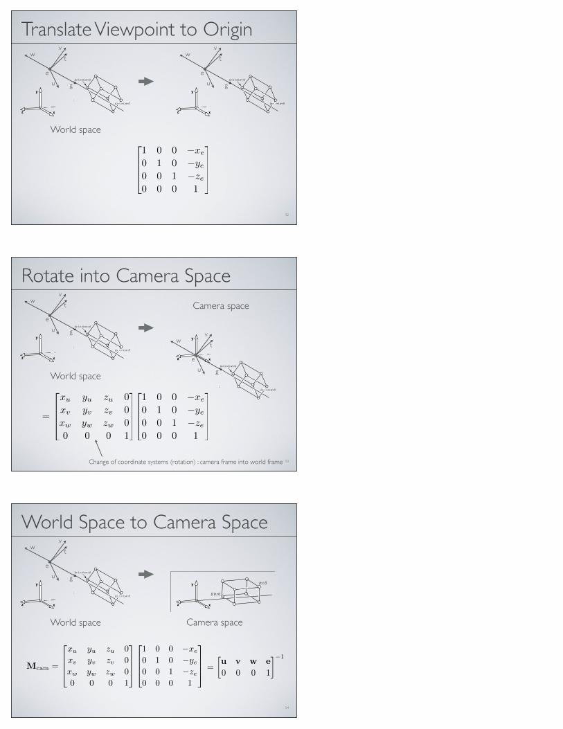
Translate Viewpoint to Origint
g
w
e
u
v
1 0 0 −xe
0 1 0 −ye0 0 1 −ze0 0 0 1
World space
!
!
!
!
!
!
!
!
7.1. Viewing Transformations 149
Figure 7.5. The orthographic view volume is along the negative z-axis, so f is a morenegative number than n, thus n > f.
the bounding planes as follows:
x = l ! left plane,
x = r ! right plane,
y = b ! bottom plane,
y = t ! top plane,
z = n ! near plane,
z = f ! far plane.
That vocabulary assumes a viewer who is looking along the minus z-axis with
Figure 7.4. The ortho-graphic view volume.
his head pointing in the y-direction. 1 This implies that n > f , which may beunintuitive, but if you assume the entire orthographic view volume has negative zvalues then the z = n “near” plane is closer to the viewer if and only if n > f ;here f is a smaller number than n, i.e., a negative number of larger absolute valuethan n.
This concept is shown in Figure 7.5. The transform from orthographic view
volume to the canonical view volume is another windowing transform, so we can
simply substitute the bounds of the orthographic and canonical view volumes into
Equation 6.7 to obtain the matrix for this transformation: n and f appear in whatmight seem like reverseorder because n " f ,rather than f " n, is apositive number.
Morth =
!
"
"
#
2r!l 0 0 " r+l
r!l
0 2
t!b0 " t+b
t!b
0 0 2n!f
" n+tn!f
0 0 0 1
$
%
%
&
(7.3)
1Most programmers find it intuitive to have the x-axis pointing right and the y-axis pointing up. Ina right-handed coordinate system, this implies that we are looking in the !z direction. Some systemsuse a left-handed coordinate system for viewing so that the gaze direction is along +z. Which is bestis a matter of taste, and this text assumes a right-handed coordinate system. A reference that argues
for the left-handed system instead is given in the notes at the end of the chapter.
!
!
!
!
!
!
!
!
7.1. Viewing Transformations 149
Figure 7.5. The orthographic view volume is along the negative z-axis, so f is a morenegative number than n, thus n > f.
the bounding planes as follows:
x = l ! left plane,
x = r ! right plane,
y = b ! bottom plane,
y = t ! top plane,
z = n ! near plane,
z = f ! far plane.
That vocabulary assumes a viewer who is looking along the minus z-axis with
Figure 7.4. The ortho-graphic view volume.
his head pointing in the y-direction. 1 This implies that n > f , which may beunintuitive, but if you assume the entire orthographic view volume has negative zvalues then the z = n “near” plane is closer to the viewer if and only if n > f ;here f is a smaller number than n, i.e., a negative number of larger absolute valuethan n.
This concept is shown in Figure 7.5. The transform from orthographic view
volume to the canonical view volume is another windowing transform, so we can
simply substitute the bounds of the orthographic and canonical view volumes into
Equation 6.7 to obtain the matrix for this transformation: n and f appear in whatmight seem like reverseorder because n " f ,rather than f " n, is apositive number.
Morth =
!
"
"
#
2r!l 0 0 " r+l
r!l
0 2
t!b0 " t+b
t!b
0 0 2n!f
" n+tn!f
0 0 0 1
$
%
%
&
(7.3)
1Most programmers find it intuitive to have the x-axis pointing right and the y-axis pointing up. Ina right-handed coordinate system, this implies that we are looking in the !z direction. Some systemsuse a left-handed coordinate system for viewing so that the gaze direction is along +z. Which is bestis a matter of taste, and this text assumes a right-handed coordinate system. A reference that argues
for the left-handed system instead is given in the notes at the end of the chapter.
53
Rotate into Camera Spacet
g
w
e
u
v
World space
1 0 0 −xe
0 1 0 −ye0 0 1 −ze0 0 0 1
t
g
w
e
u
v
=
xu yu zu 0xv yv zv 0xw yw zw 00 0 0 1
Camera space
Change of coordinate systems (rotation) : camera frame into world frame
!
!
!
!
!
!
!
!
7.1. Viewing Transformations 149
Figure 7.5. The orthographic view volume is along the negative z-axis, so f is a morenegative number than n, thus n > f.
the bounding planes as follows:
x = l ! left plane,
x = r ! right plane,
y = b ! bottom plane,
y = t ! top plane,
z = n ! near plane,
z = f ! far plane.
That vocabulary assumes a viewer who is looking along the minus z-axis with
Figure 7.4. The ortho-graphic view volume.
his head pointing in the y-direction. 1 This implies that n > f , which may beunintuitive, but if you assume the entire orthographic view volume has negative zvalues then the z = n “near” plane is closer to the viewer if and only if n > f ;here f is a smaller number than n, i.e., a negative number of larger absolute valuethan n.
This concept is shown in Figure 7.5. The transform from orthographic view
volume to the canonical view volume is another windowing transform, so we can
simply substitute the bounds of the orthographic and canonical view volumes into
Equation 6.7 to obtain the matrix for this transformation: n and f appear in whatmight seem like reverseorder because n " f ,rather than f " n, is apositive number.
Morth =
!
"
"
#
2r!l 0 0 " r+l
r!l
0 2
t!b0 " t+b
t!b
0 0 2n!f
" n+tn!f
0 0 0 1
$
%
%
&
(7.3)
1Most programmers find it intuitive to have the x-axis pointing right and the y-axis pointing up. Ina right-handed coordinate system, this implies that we are looking in the !z direction. Some systemsuse a left-handed coordinate system for viewing so that the gaze direction is along +z. Which is bestis a matter of taste, and this text assumes a right-handed coordinate system. A reference that argues
for the left-handed system instead is given in the notes at the end of the chapter.
54
World Space to Camera Spacet
g
w
e
u
v
!
!
!
!
!
!
!
!
7.1. Viewing Transformations 149
Figure 7.5. The orthographic view volume is along the negative z-axis, so f is a morenegative number than n, thus n > f.
the bounding planes as follows:
x = l ! left plane,
x = r ! right plane,
y = b ! bottom plane,
y = t ! top plane,
z = n ! near plane,
z = f ! far plane.
That vocabulary assumes a viewer who is looking along the minus z-axis with
Figure 7.4. The ortho-graphic view volume.
his head pointing in the y-direction. 1 This implies that n > f , which may beunintuitive, but if you assume the entire orthographic view volume has negative zvalues then the z = n “near” plane is closer to the viewer if and only if n > f ;here f is a smaller number than n, i.e., a negative number of larger absolute valuethan n.
This concept is shown in Figure 7.5. The transform from orthographic view
volume to the canonical view volume is another windowing transform, so we can
simply substitute the bounds of the orthographic and canonical view volumes into
Equation 6.7 to obtain the matrix for this transformation: n and f appear in whatmight seem like reverseorder because n " f ,rather than f " n, is apositive number.
Morth =
!
"
"
#
2r!l 0 0 " r+l
r!l
0 2
t!b0 " t+b
t!b
0 0 2n!f
" n+tn!f
0 0 0 1
$
%
%
&
(7.3)
1Most programmers find it intuitive to have the x-axis pointing right and the y-axis pointing up. Ina right-handed coordinate system, this implies that we are looking in the !z direction. Some systemsuse a left-handed coordinate system for viewing so that the gaze direction is along +z. Which is bestis a matter of taste, and this text assumes a right-handed coordinate system. A reference that argues
for the left-handed system instead is given in the notes at the end of the chapter.
Camera spaceWorld space
Mcam =
xu yu zu 0xv yv zv 0xw yw zw 00 0 0 1
1 0 0 −xe
0 1 0 −ye0 0 1 −ze0 0 0 1
=
�u v w e0 0 0 1
�−1
Pipeline of Transformations
55
!
!
!
!
!
!
!
!
7.1. Viewing Transformations 147
object space
world space
camera space
canonicalview volume
scre
en
sp
ace
modelingtransformation
viewporttransformation
projectiontransformation
cameratransformation
Figure 7.2. The sequence of spaces and transformations that gets objects from their
original coordinates into screen space.
space) to camera coordinates or places them in camera space. The projection
transformation moves points from camera space to the canonical view volume.
Finally, the viewport transformation maps the canonical view volume to screen Other names: camera
space is also “eye space”
and the camera
transformation is
sometimes the “viewing
transformation;” the
canonical view volume is
also “clip space” or
“normalized device
coordinates;” screen space
is also “pixel coordinates.”
space.
Each of these transformations is individually quite simple. We’ll discuss them
in detail for the orthographic case beginning with the viewport transformation,
then cover the changes required to support perspective projection.
7.1.1 The Viewport Transformation
We begin with a problemwhose solution will be reused for any viewing condition.
We assume that the geometry we want to view is in the canonical view volume The word “canonical” crops
up again—it means
something arbitrarily
chosen for convenience.
For instance, the unit circle
could be called the
“canonical circle.”
and we wish to view it with an orthographic camera looking in the !z direction.The canonical view volume is the cube containing all 3D points whose Cartesian
coordinates are between !1 and +1—that is, (x, y, z) " [!1, 1]3 (Figure 7.3).We project x = !1 to the left side of the screen, x = +1 to the right side of thescreen, y = !1 to the bottom of the screen, and y = +1 to the top of the screen.
Recall the conventions for pixel coordinates fromChapter 3: each pixel “owns”
a unit square centered at integer coordinates; the image boundaries have a half-
unit overshoot from the pixel centers; and the smallest pixel center coordinates
Mvp
: Translate and rotate world space into camera space
Morth
Mcam
Mcam
Pipeline of Transformations
56
!
!
!
!
!
!
!
!
7.1. Viewing Transformations 147
object space
world space
camera space
canonicalview volume
scre
en
sp
ace
modelingtransformation
viewporttransformation
projectiontransformation
cameratransformation
Figure 7.2. The sequence of spaces and transformations that gets objects from their
original coordinates into screen space.
space) to camera coordinates or places them in camera space. The projection
transformation moves points from camera space to the canonical view volume.
Finally, the viewport transformation maps the canonical view volume to screen Other names: camera
space is also “eye space”
and the camera
transformation is
sometimes the “viewing
transformation;” the
canonical view volume is
also “clip space” or
“normalized device
coordinates;” screen space
is also “pixel coordinates.”
space.
Each of these transformations is individually quite simple. We’ll discuss them
in detail for the orthographic case beginning with the viewport transformation,
then cover the changes required to support perspective projection.
7.1.1 The Viewport Transformation
We begin with a problemwhose solution will be reused for any viewing condition.
We assume that the geometry we want to view is in the canonical view volume The word “canonical” crops
up again—it means
something arbitrarily
chosen for convenience.
For instance, the unit circle
could be called the
“canonical circle.”
and we wish to view it with an orthographic camera looking in the !z direction.The canonical view volume is the cube containing all 3D points whose Cartesian
coordinates are between !1 and +1—that is, (x, y, z) " [!1, 1]3 (Figure 7.3).We project x = !1 to the left side of the screen, x = +1 to the right side of thescreen, y = !1 to the bottom of the screen, and y = +1 to the top of the screen.
Recall the conventions for pixel coordinates fromChapter 3: each pixel “owns”
a unit square centered at integer coordinates; the image boundaries have a half-
unit overshoot from the pixel centers; and the smallest pixel center coordinates
Mvp
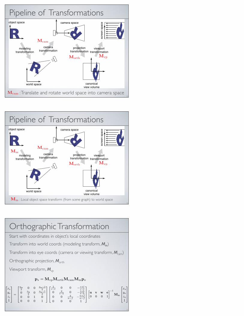
: Local object space transform (from scene graph) to world space
Morth
McamMm
Mm
Orthographic Transformation Start with coordinates in object’s local coordinates
Transform into world coords (modeling transform, Mm)
Transform into eye coords (camera or viewing transform, Mcam)
Orthographic projection, Morth
Viewport transform, Mvp
57
xs
ys
zc
1
=
nx2 0 0 nx−1
2
0 ny
2 0 ny−12
0 0 1 00 0 0 1
2r−l 0 0 − r+l
r−l
0 2t−b 0 − t+b
t−b
0 0 2n−f −n+f
n−f
0 0 0 1
�u v w e0 0 0 1
�−1
Mm
xo
yo
zo
1
ps = MvpMorthMcamMmpo
Perspective Projection
Perspective Projection
59
60
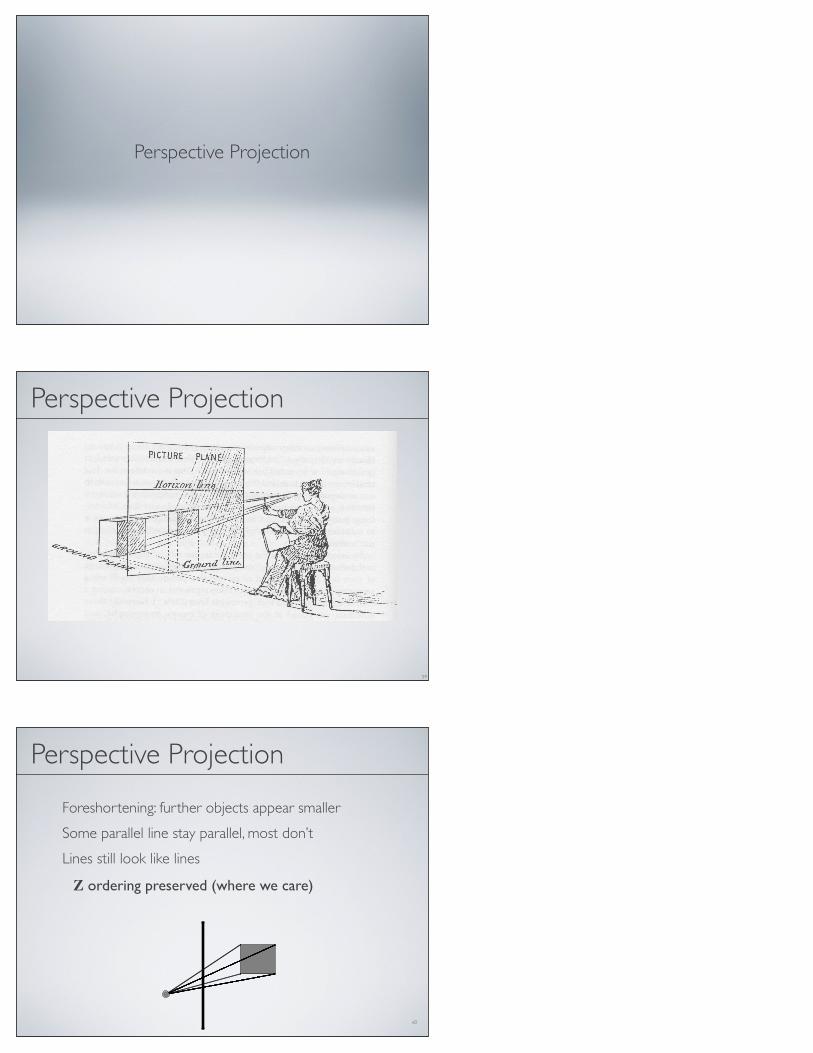
Perspective Projection
Foreshortening: further objects appear smaller
Some parallel line stay parallel, most don’t
Lines still look like lines
Z ordering preserved (where we care)
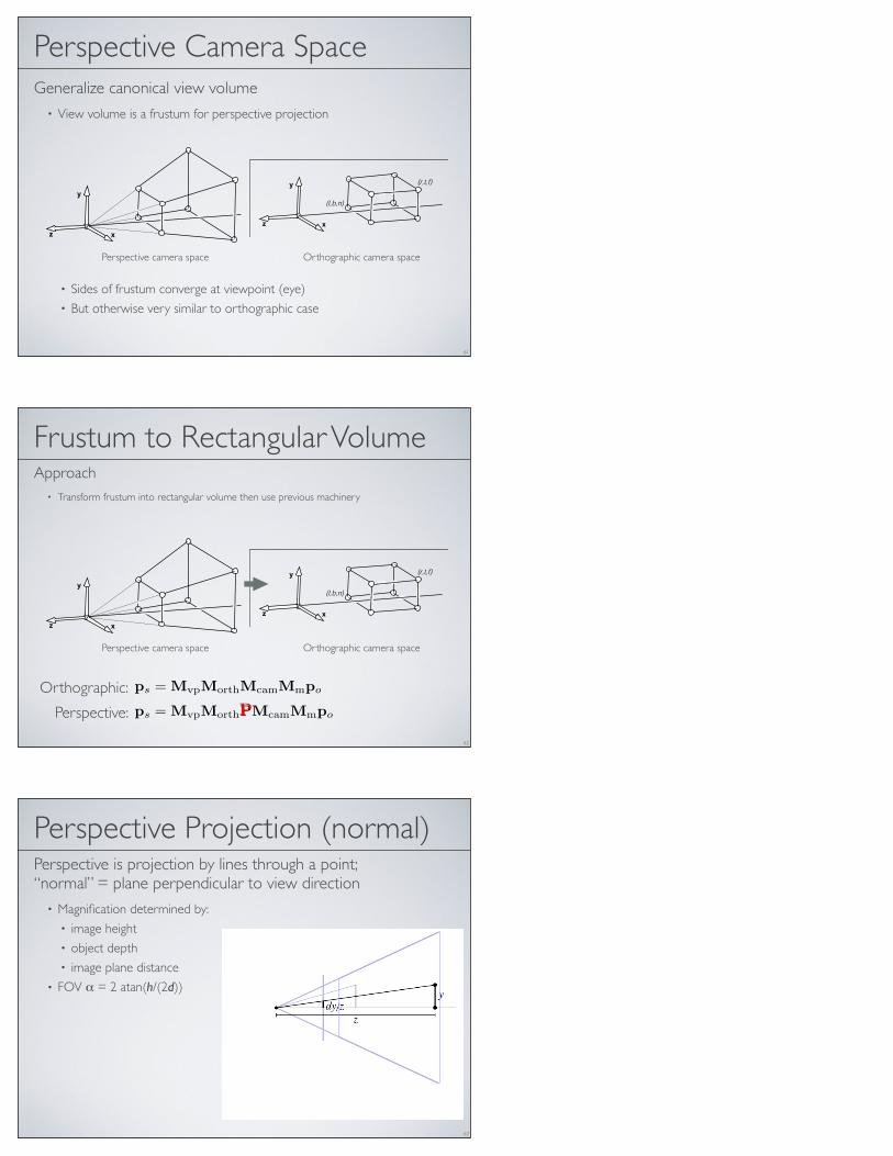
Perspective Camera SpaceGeneralize canonical view volume
• View volume is a frustum for perspective projection
• Sides of frustum converge at viewpoint (eye)• But otherwise very similar to orthographic case
61
!
!
!
!
!
!
!
!
7.1. Viewing Transformations 149
Figure 7.5. The orthographic view volume is along the negative z-axis, so f is a morenegative number than n, thus n > f.
the bounding planes as follows:
x = l ! left plane,
x = r ! right plane,
y = b ! bottom plane,
y = t ! top plane,
z = n ! near plane,
z = f ! far plane.
That vocabulary assumes a viewer who is looking along the minus z-axis with
Figure 7.4. The ortho-graphic view volume.
his head pointing in the y-direction. 1 This implies that n > f , which may beunintuitive, but if you assume the entire orthographic view volume has negative zvalues then the z = n “near” plane is closer to the viewer if and only if n > f ;here f is a smaller number than n, i.e., a negative number of larger absolute valuethan n.
This concept is shown in Figure 7.5. The transform from orthographic view
volume to the canonical view volume is another windowing transform, so we can
simply substitute the bounds of the orthographic and canonical view volumes into
Equation 6.7 to obtain the matrix for this transformation: n and f appear in whatmight seem like reverseorder because n " f ,rather than f " n, is apositive number.
Morth =
!
"
"
#
2r!l 0 0 " r+l
r!l
0 2
t!b0 " t+b
t!b
0 0 2n!f
" n+tn!f
0 0 0 1
$
%
%
&
(7.3)
1Most programmers find it intuitive to have the x-axis pointing right and the y-axis pointing up. Ina right-handed coordinate system, this implies that we are looking in the !z direction. Some systemsuse a left-handed coordinate system for viewing so that the gaze direction is along +z. Which is bestis a matter of taste, and this text assumes a right-handed coordinate system. A reference that argues
for the left-handed system instead is given in the notes at the end of the chapter.
Perspective camera space Orthographic camera space
Frustum to Rectangular VolumeApproach
• Transform frustum into rectangular volume then use previous machinery
62
!
!
!
!
!
!
!
!
7.1. Viewing Transformations 149
Figure 7.5. The orthographic view volume is along the negative z-axis, so f is a morenegative number than n, thus n > f.
the bounding planes as follows:
x = l ! left plane,
x = r ! right plane,
y = b ! bottom plane,
y = t ! top plane,
z = n ! near plane,
z = f ! far plane.
That vocabulary assumes a viewer who is looking along the minus z-axis with
Figure 7.4. The ortho-graphic view volume.
his head pointing in the y-direction. 1 This implies that n > f , which may beunintuitive, but if you assume the entire orthographic view volume has negative zvalues then the z = n “near” plane is closer to the viewer if and only if n > f ;here f is a smaller number than n, i.e., a negative number of larger absolute valuethan n.
This concept is shown in Figure 7.5. The transform from orthographic view
volume to the canonical view volume is another windowing transform, so we can
simply substitute the bounds of the orthographic and canonical view volumes into
Equation 6.7 to obtain the matrix for this transformation: n and f appear in whatmight seem like reverseorder because n " f ,rather than f " n, is apositive number.
Morth =
!
"
"
#
2r!l 0 0 " r+l
r!l
0 2
t!b0 " t+b
t!b
0 0 2n!f
" n+tn!f
0 0 0 1
$
%
%
&
(7.3)
1Most programmers find it intuitive to have the x-axis pointing right and the y-axis pointing up. Ina right-handed coordinate system, this implies that we are looking in the !z direction. Some systemsuse a left-handed coordinate system for viewing so that the gaze direction is along +z. Which is bestis a matter of taste, and this text assumes a right-handed coordinate system. A reference that argues
for the left-handed system instead is given in the notes at the end of the chapter.
Perspective camera space Orthographic camera space
ps = MvpMorthPMcamMmpo
ps = MvpMorthMcamMmpoOrthographic:
Perspective: P
Perspective Projection (normal)Perspective is projection by lines through a point; “normal” = plane perpendicular to view direction
• Magnification determined by:• image height• object depth• image plane distance
• FOV α = 2 atan(h/(2d))
63
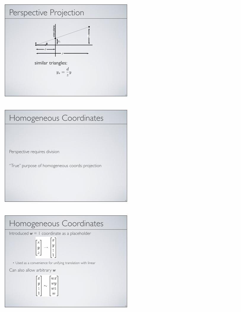
Perspective Projection
similar triangles:
64
ys =d
zy
Homogeneous Coordinates
Perspective requires division
“True” purpose of homogeneous coords: projection
65
Homogeneous Coordinates Introduced w = 1 coordinate as a placeholder
• Used as a convenience for unifying translation with linear
Can also allow arbitrary w
66

Implications of w
All scalar multiples of a 4-vector are equivalent
When w is not zero, can divide by w• These points represent normal affine points
When w is zero, it’s a point at infinity, a.k.a. a direction• This is the point where parallel lines intersect• Can also think of it as the vanishing point
67
Projective Transform (Homography)
Allows for division necessary for perspective
Compare to affine transform which leaves w=1
68
a11 a12 a13 xt
a21 a22 a23 yta31 a32 a33 zt0 0 0 1
affine transform
xwywzw
1
∼
xyzw
=
a11 a12 a13 xt
a21 a22 a23 yta31 a32 a33 zte f g h
xyz1
projective transform
Perspective Projection
similar triangles:
69
ys =d
zy

Perspective Projection w/o Z
to implement perspective, just move z to w:
70
xs
ys1
=
dxzdyz
1
∼
dxdyz
=
d 0 0 00 d 0 00 0 1 0
xyz1
Perspective Projection with ZStraightforward extension doesn’t preserve z coordinates
71
xs
yszs1
∼
xyzz
=
d 0 0 00 d 0 00 0 1 00 0 1 0
xyz1
z = z so zs =z
z= 1
xs
yszs1
∼
xyzz
=
d 0 0 00 d 0 00 0 a b0 0 1 0
xyz1
To carry through z-coordinates use alternative formulation
Perspective Projection with Z
Here
Set and preserve depths at near and far planes• For• For • Solve for a and b we obtain
72
xs
yszs1
∼
xyzz
=
d 0 0 00 d 0 00 0 a b0 0 1 0
xyz1
z = az + b and zs =az + b
z
z = n we want zs = nz = f we want zs = f
d = n
result: a = n+ f and b = −fn (try it)
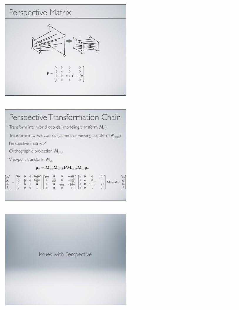
Perspective Matrix
73
P =
n 0 0 00 n 0 00 0 n + f −fn0 0 1 0
Perspective Transformation ChainTransform into world coords (modeling transform, Mm)
Transform into eye coords (camera or viewing transform Mcam)
Perspective matrix, P
Orthographic projection, Morth
Viewport transform, Mvp
74
ps = MvpMorthPMcamMmpo
xs
ys
zc
1
=
nx2 0 0 nx−1
2
0 ny
2 0 ny−12
0 0 1 00 0 0 1
2r−l 0 0 − r+l
r−l
0 2t−b 0 − t+b
t−b
0 0 2n−f −n+f
n−f
0 0 0 1
n 0 0 00 n 0 00 0 n + f −fn0 0 1 0
McamMm
xo
yo
zo
1
Issues with Perspective

Normal Perspective and FOV
FOV α = 2 atan(h/(2d))
76
Field of View
Angle between rays along opposite edges of perspective image• Easy to compute only for “normal” perspective• Have to decide to measure vert., horiz., or diag.
In cameras, determined by focal length• Confusing because of many image sizes• For 35mm format (36mm by 24mm image)
• 18mm = 67° v.f.o.v. — super-wide angle• 28mm = 46° v.f.o.v. — wide angle• 50mm = 27° v.f.o.v. — “normal”• 100mm = 14° v.f.o.v. — narrow angle (“telephoto”)
77
Field of ViewDetermines “strength” of perspective effects
close viewpointwide angleprominent
foreshortening
far viewpointnarrow angle
little foreshortening
[Ans
el A
dam
s]
78
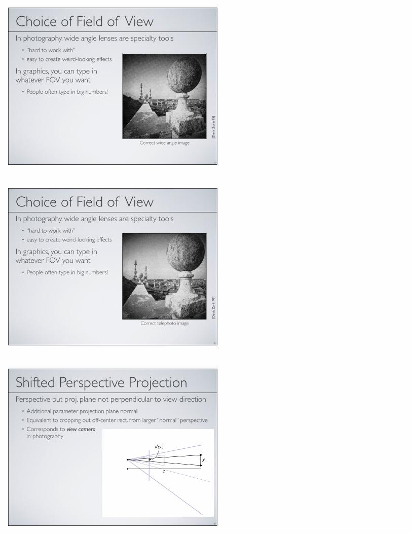
Choice of Field of ViewIn photography, wide angle lenses are specialty tools
• “hard to work with” • easy to create weird-looking effects
In graphics, you can type in whatever FOV you want
• People often type in big numbers!
[Den
is Z
orin
95]
79
Correction of Geometric Perceptual Distortions in Pictures.
Denis Zorin, Alan H. Barr
California Institute of Technology, Pasadena, CA 91125
AbstractWe suggest an approachfor correcting several types of perceived
geometric distortions in computer-generated and photographic im-ages. The approach is based on a mathematical formalization ofdesirable properties of pictures.
From a small set of simple assumptions we obtain perceptuallypreferable viewing transformations and show that these transforma-tions can be decomposed into a perspective or parallel projectionfollowed by a planar transformation. The decomposition is eas-ily implemented and provides a convenient framework for furtheranalysis of the image mapping.
We prove that two perceptually important properties are incom-patible and cannot be satisfied simultaneously. It is impossible toconstruct a viewing transformation such that the images of all linesare straight and the images of all spheres are exact circles. Percep-tually preferable tradeoffs between these two types of distortionscan depend on the content of the picture. We construct parametricfamilies of transformations with parameters representing the rela-tive importance of the perceptual characteristics. By adjusting thesettings of the parameters we can minimize the overall distortion ofthe picture.
It turns out that a simple family of transformations producesresults that are sufficiently close to optimal. We implement the pro-posed transformations and apply them to computer-generated andphotographic perspective projection images. Our transformationscan considerably reduce distortion in wide-angle motion picturesand computer-generated animations.Keywords: Perception, distortion, viewing transformations,
perspective.
The process of realistic image synthesis can be subdivided intotwo stages: modeling the physics of light propagation in three-dimensional environments and projecting the geometry of three-dimensional space into the picture plane (the “viewing transfor-mation.”) While the first stage is relatively independent of ourunderstanding of visual perception, the viewing transformations arebased on the fact that we are able to perceive two-dimensionalpatterns - pictures - as reasonably accurate representations of three-dimensional objects. We can evaluate the quality of modeling thepropagationof light objectively, by comparing calculatedphotomet-ric values with experimental measurements. For viewing transfor-mations the quality is much more subjective.
a.
b.
Figure 1. a. Wide-angle pinhole photograph taken on the roof of the Church
of St. Ignatzio in Rome, classical example of perspective distortions from
[Pir70]; reprinted with the permission of Cambridge University Press. b.
Corrected version of the picture with transformation applied.
The perspective projection 1 is the viewing transformation thathas been primarily used for producing realistic images, in art, pho-tography and in computer graphics.
One motivation for using perspective projection in computer
1By perspective projection or linear perspective we mean either central projectionor parallel projection into a plane.
!"#$%&&%'()*')$+,")-%.%*+/01+#-)2'34)'5)3+#*)'#)+//)'5)*1%&)6'#,)5'#)3"#&'(+/)'#)2/+&&#''$)7&")%&).#+(*"-)6%*1'7*)5"")3#'8%-"-))*1+*)2'3%"&)+#")('*)$+-")'#)-%&*#%97*"-)5'#)3#'5%*)'#)2'$$"#2%+/))+-8+(*+.":)*1")2'34#%.1*)('*%2":)*1")*%*/")'5)*1")379/%2+*%'()+(-)%*&)-+*")+33"+#:)+(-)('*%2")%&).%8"()*1+*)2'34%(.)%&)94)3"#$%&&%'()'5);<=:)>(2?))@')2'34)'*1"#6%&":)*')#"379/%&1:)*')3'&*)'()&"#8"#&:)'#)*')#"-%&*#%97*")*')/%&*&:)#"A7%#"&)3#%'#)&3"2%5%2)3"#$%&&%'()+(-0'#)+)5""?)BCDDE));<=FGFHDIDCFIGCFJ0DE0GGHKLM?EG))) 257
Correct wide angle image
Choice of Field of ViewIn photography, wide angle lenses are specialty tools
• “hard to work with” • easy to create weird-looking effects
In graphics, you can type in whatever FOV you want
• People often type in big numbers!
[Den
is Z
orin
95]
80
Correction of Geometric Perceptual Distortions in Pictures.
Denis Zorin, Alan H. Barr
California Institute of Technology, Pasadena, CA 91125
AbstractWe suggest an approachfor correcting several types of perceived
geometric distortions in computer-generated and photographic im-ages. The approach is based on a mathematical formalization ofdesirable properties of pictures.
From a small set of simple assumptions we obtain perceptuallypreferable viewing transformations and show that these transforma-tions can be decomposed into a perspective or parallel projectionfollowed by a planar transformation. The decomposition is eas-ily implemented and provides a convenient framework for furtheranalysis of the image mapping.
We prove that two perceptually important properties are incom-patible and cannot be satisfied simultaneously. It is impossible toconstruct a viewing transformation such that the images of all linesare straight and the images of all spheres are exact circles. Percep-tually preferable tradeoffs between these two types of distortionscan depend on the content of the picture. We construct parametricfamilies of transformations with parameters representing the rela-tive importance of the perceptual characteristics. By adjusting thesettings of the parameters we can minimize the overall distortion ofthe picture.
It turns out that a simple family of transformations producesresults that are sufficiently close to optimal. We implement the pro-posed transformations and apply them to computer-generated andphotographic perspective projection images. Our transformationscan considerably reduce distortion in wide-angle motion picturesand computer-generated animations.Keywords: Perception, distortion, viewing transformations,
perspective.
The process of realistic image synthesis can be subdivided intotwo stages: modeling the physics of light propagation in three-dimensional environments and projecting the geometry of three-dimensional space into the picture plane (the “viewing transfor-mation.”) While the first stage is relatively independent of ourunderstanding of visual perception, the viewing transformations arebased on the fact that we are able to perceive two-dimensionalpatterns - pictures - as reasonably accurate representations of three-dimensional objects. We can evaluate the quality of modeling thepropagationof light objectively, by comparing calculatedphotomet-ric values with experimental measurements. For viewing transfor-mations the quality is much more subjective.
a.
b.
Figure 1. a. Wide-angle pinhole photograph taken on the roof of the Church
of St. Ignatzio in Rome, classical example of perspective distortions from
[Pir70]; reprinted with the permission of Cambridge University Press. b.
Corrected version of the picture with transformation applied.
The perspective projection 1 is the viewing transformation thathas been primarily used for producing realistic images, in art, pho-tography and in computer graphics.
One motivation for using perspective projection in computer
1By perspective projection or linear perspective we mean either central projectionor parallel projection into a plane.
!"#$%&&%'()*')$+,")-%.%*+/01+#-)2'34)'5)3+#*)'#)+//)'5)*1%&)6'#,)5'#)3"#&'(+/)'#)2/+&&#''$)7&")%&).#+(*"-)6%*1'7*)5"")3#'8%-"-))*1+*)2'3%"&)+#")('*)$+-")'#)-%&*#%97*"-)5'#)3#'5%*)'#)2'$$"#2%+/))+-8+(*+.":)*1")2'34#%.1*)('*%2":)*1")*%*/")'5)*1")379/%2+*%'()+(-)%*&)-+*")+33"+#:)+(-)('*%2")%&).%8"()*1+*)2'34%(.)%&)94)3"#$%&&%'()'5);<=:)>(2?))@')2'34)'*1"#6%&":)*')#"379/%&1:)*')3'&*)'()&"#8"#&:)'#)*')#"-%&*#%97*")*')/%&*&:)#"A7%#"&)3#%'#)&3"2%5%2)3"#$%&&%'()+(-0'#)+)5""?)BCDDE));<=FGFHDIDCFIGCFJ0DE0GGHKLM?EG))) 257
Correct telephoto image
Shifted Perspective ProjectionPerspective but proj. plane not perpendicular to view direction
• Additional parameter projection plane normal• Equivalent to cropping out off-center rect. from larger “normal” perspective• Corresponds to view camera
in photography
81

Why Shifted Perspective?Control convergence of parallel lines
Standard example: architecture• Buildings are taller than you, so you look up• Top of building is farther away, so it looks smaller
Solution: make projection plane parallel to facade• Top of building is the same distance from the projection plane
82
[Phi
lip G
reen
spun
]
camera tilted up: converging vertical lines83
[Phi
lip G
reen
spun
]
lens shifted up: parallel vertical lines84