cs - 511 - studentsfounder.com · prepared by: arshad iqbal, lecturer (cs/it), ibms, the university...
TRANSCRIPT

Prepared by: ARSHAD IQBAL, Lecturer (CS/IT), IBMS, The University of Agriculture, Peshawar 1
Discipline: BS (CS) 6th SemesterSubject: Computer Communication and NetworksNotes: From Week No. 01 – 06Prepared by: ARSHAD IQBAL, Lecturer (CS/IT), IBMS, The University of
Agriculture, PeshawarCourse Code: CS - 511
Prepared by: ARSHAD IQBAL, Lecturer (CS/IT), IBMS, The University of Agriculture, Peshawar 2
Course Objectives
To introduce students the concept of Computer Communication, Network layers, Network models (OSI & TCP/IP), Protocols & Standards, Analogue and Digital Transmission. Emphasis(stress/importance) is given on the understanding of modern network concepts.

Prepared by: ARSHAD IQBAL, Lecturer (CS/IT), IBMS, The University of Agriculture, Peshawar 3
Week No. 01: Introduction to Data Communication
Communication:• Communication means to communicate / exchange data between two parties, may be
two persons or may be two computers.
• The word data refers to information presented in whatever form is agreed upon by the parties creating and using the data. In the context of computer information systems, data are represented by binary information units (or bits) produced and consumed in the form of 0s and 1s.
Data Communication:• Data communication is the process of transmitting & receiving data in an orderly way,
so the data that arrives at its destination / target is an accurate duplication of data that was sent.
Sender Receiver
• When the data travels a short distance, such that when data is send from computer to printer, the communication referred to as “Local Communication”. Local communication usually occurs face to face.
• When the data travels a long distance, the communication referred as “TeleCommunication”. The prefix “Tele” is derived from a Greek word which means “Far”.
For example, a person make a call to another person setting in the next room or next building is an example of Telecommunication.
DDaattaa ccoommmmuunniiccaattiioonn iiss tthhee eexxcchhaannggee ooff ddaattaa ((iinn tthhee
ffoorrmm ooff 00ss aanndd 11ss)) bbeettwweeeenn ttwwoo ddeevviicceess vviiaa ssoommee
ffoorrmm ooff ttrraannssmmiissssiioonn mmeeddiiuumm ssuucchh aass aa wwiirree ccaabbllee..
DDaattaa ccoommmmuunniiccaattiioonnss iiss tthhee ttrraannssffeerr ooff ddiiggiittaall oorraannaalloogg ddaattaa uussiinngg ddiiggiittaall oorr aannaalloogg ssiiggnnaallss..
TThhee tteerrmm tteelleeccoommmmuunniiccaattiioonn mmeeaannss ccoommmmuunniiccaattiioonn aatt aaddiissttaannccee.. TTeelleeccoommmmuunniiccaattiioonnss –– tthhee ssttuuddyy oofftteelleepphhoonneess aanndd tthhee ssyysstteemmss tthhaatt ttrraannssmmiitt tteelleepphhoonneessiiggnnaallss..
Prepared by: ARSHAD IQBAL, Lecturer (CS/IT), IBMS, The University of Agriculture, Peshawar 4
Fundamental Characteristics of Data Communication:
The effective communication system depends on the following four fundamental characteristics:
1. Delivery: - The system must deliver data to the correct destination. The intended device or user must receive data.
2. Accuracy: - The system must deliver data accurately. Data that have been altered in transmission are left uncorrected and unusable.
3. Timelines: - The system must deliver data in timely manner. Data delivered late areuseless. In case of audio & video, timely delivery means delivering data as they are produced, in the same order that they are produced and without significant delay. This kind of delivery is called Real Time Transmission.
4. Jitter: - Jitter refers to the variation in the packet arrival time. It is the uneven (irregular)delay in the delivery of audio or video packets.
Data communication Components:
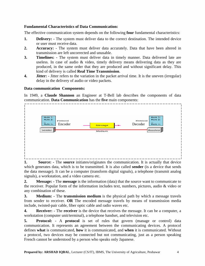
In 1949, a Claude Shannon an Engineer at T-Bell lab describes the components of data communication. Data Communication has the five main components:
Encoder Decoder
1. Source: - The source initiates/originates the communication. It is actually that device which generates data, which is to be transmitted. It is also called sender (is a device that sends the data message). It can be a computer (transform digital signals), a telephone (transmit analog signals), a workstation, and a video camera etc.
2. Message: - The message is the information (data) that the source want to communicate to the receiver. Popular form of the information includes text, numbers, pictures, audio & video or any combination of these.
3. Medium: - The transmission medium is the physical path by which a message travels from sender to receiver. OR The encoded message travels by means of transmission media include, twisted-pair cable, fiber optic cable and radio waves etc.
4. Receiver: - The receiver is the device that receives the message. It can be a computer, a workstation (computer unit/terminal), a telephone handset, and television etc.
5. Protocol: - A protocol is set of rules that govern (manage or control) data communication. It represents an agreement between the communicating devices. A protocol defines what is communicated, how it is communicated, and when it is communicated. Without a protocol, two devices may be connected but not communicating, just as a person speaking French cannot be understood by a person who speaks only Japanese.

Prepared by: ARSHAD IQBAL, Lecturer (CS/IT), IBMS, The University of Agriculture, Peshawar 5
Networks:A network is a set of devices (often referred to as nodes) connected by media links. A node can be a computer, printer, or any other device capable of sending and /or receiving data generated by other nodes on the networks. The links connecting the devices are often called communication channels. Or a group of computers and other devices joint together through some transmission medium is called Computer Network. Or the concept of connected computers sharing resources is called Networking.
Network criteria:To be considered effective and efficient, a network must meet a number of criteria. The most important of these are:
• Performance• Reliability• Security
Performance:Performance can be measured in many ways, including transit time (transfer/travel time) and response time. Transit time is the amount of time required for a message to travel from one device to another device. Response time is the elapsed time between an inquiry and a response.
The performance of a network depends on a number of factors, including the number of users, the type of transmission medium, the capabilities (abilities/capacities) of the connected hardware, and the efficiency (effectiveness) of the software.
Reliability:In addition to accuracy of delivery, network reliability is measured by frequency of failure, recovery time (the time it takes a link to recover from a failure), and catastrophe (the networks robustness (strength/toughness/healthiness) in a catastrophe (disaster)).
• Frequency of failure: All networks fail occasionally (irregularly/rarely). A network that fails often, however, is a little value to a user.
• Recovery time of a network after a failure: how long does it take to restore service? A network that recovers quickly is more useful than one that does not.
• Catastrophe: Networks must be protected from catastrophic (disastrous) events such as fire, earthquake, or theft. One protection against unforeseen(unexpected/suddenly) damage is a reliable system to back up network software.
Security:Network security issues include protecting data from unauthorized access and viruses.
• Unauthorized access: For a network to be useful, a sensitive data must be protected from unauthorized access. Protection can be accomplished (achieved) at a number of levels. At the lowest level are user identification codes and passwords. At a higher level are encryption techniques. In these mechanisms, data are systematically altered in such a way that if they are intercepted(interrupted/catch/stop) by an unauthorized user, they will be unintelligible(meaningless).
• Viruses: Because a network is accessible from many points, it can be susceptible(exposed/at risk/open to) to computer viruses. A virus is an illicitly (illegally)introduced code that damages the system. A good network is protected from viruses by hardware and software designed specifically for that purpose.
Prepared by: ARSHAD IQBAL, Lecturer (CS/IT), IBMS, The University of Agriculture, Peshawar 6
Protocol and Standards:
Protocol: A protocol is set of rules that govern (manage or control) data communication. It represents an agreement between the communicating devices. A protocol defines what is communicated, how it is communicated, and when it is communicated. Without a protocol, two devices may be connected but not communicating, just as a person speaking French cannot be understood by a person who speaks only Japanese.
The key elements of protocols are:
Syntax: The term syntax refers to the structure or format of data, means the order in which they are presented. For example, a simple protocol might expect the first 8-bits of data to be the address of the sender, the second 8-bits to be the address of the receiver, and the rest of the stream to be the message itself.
Semantic: The word semantic refers to the meaning of each section of bits. How is a particular pattern to be interpreted (understand or read), and what action to be taken based on that interpretation(analysis/understanding/explanation)? For example, does an address identify the route to be taken or the final destination of the message?
Timing: The term timing refers to two characteristics: when data should be sent and how fast they can be sent. For example, if a sender produces data at 100 Mbps but the receiver can process data at only 1 Mbps, the transmission will overload the receiver and some data will be lost.
Standards:
• Why have standards?• Some countries require you to drive on the right hand side of the road, some on the left,
but never, never is it left up to the individual. Although individual choice is highly desirable in many areas of human activity, there are others in which we must adhere(stick/hold/stay/remain) to accepted standards for the common good.
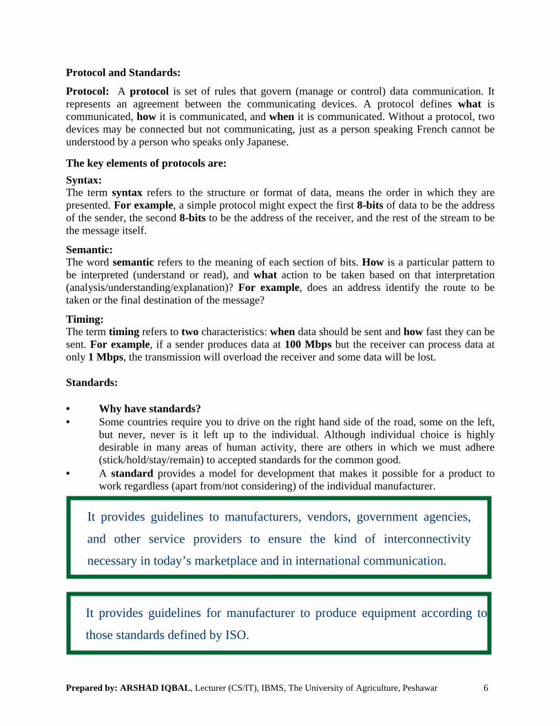
• A standard provides a model for development that makes it possible for a product to work regardless (apart from/not considering) of the individual manufacturer.
It provides guidelines to manufacturers, vendors, government agencies,
and other service providers to ensure the kind of interconnectivity
necessary in today’s marketplace and in international communication.
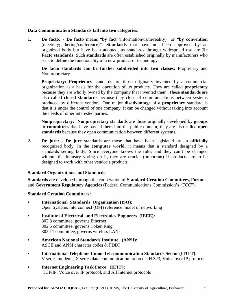
It provides guidelines for manufacturer to produce equipment according to
those standards defined by ISO.
Prepared by: ARSHAD IQBAL, Lecturer (CS/IT), IBMS, The University of Agriculture, Peshawar 7
Data Communication Standards fall into two categories:
1. De facto: - De facto means “by fact (information/truth/reality)” or “by convention (meeting/gathering/conference)”. Standards that have not been approved by an organized body but have been adopted, as standards through widespread use are De Facto standards. Such standards are often established originally by manufacturers who seek to define the functionality of a new product or technology.
De facto standards can be further subdivided into two classes: Proprietary and Nonproprietary.
Proprietary: Proprietary standards are those originally invented by a commercial organization as a basis for the operation of its products. They are called proprietarybecause they are wholly owned by the company that invented them. These standards are also called closed standards because they close of communications between systems produced by different vendors. One major disadvantage of a proprietary standard is that it is under the control of one company. It can be changed without taking into account the needs of other interested parties.
Nonproprietary: Nonproprietary standards are those originally developed by groupsor committees that have passed them into the public domain; they are also called open standards because they open communication between different systems.
2. De jure: - De jure standards are those that have been legislated by an officiallyrecognized body. In the computer world, it means that a standard designed by a standards setting body. Since everyone knows the rules and they can’t be changed without the industry voting on it, they are crucial (important) if products are to be designed to work with other vendor’s products.
Standard Organizations and Standards:
Standards are developed through the cooperation of Standard Creation Committees, Forums,and Government Regulatory Agencies (Federal Communications Commission’s “FCC”).
Standard Creation Committees:
• International Standards Organization (ISO):Open Systems Interconnect (OSI) reference model of networking
• Institute of Electrical and Electronics Engineers (IEEE): 802.3 committee, governs Ethernet802.5 committee, governs Token Ring802.11 committee, governs wireless LANs
• American National Standards Institute (ANSI):ASCII and ANSI character codes & FDDI
• International Telephone Union-Telecommunication Standards Sector (ITU-T): V series modems, X series data communication protocols H.323, Voice over IP protocol
• Internet Engineering Task Force (IETF):TCP/IP, Voice over IP protocol, and All Internet protocols
Prepared by: ARSHAD IQBAL, Lecturer (CS/IT), IBMS, The University of Agriculture, Peshawar 8
Week No. 02: Basic Concepts
Line Configuration:
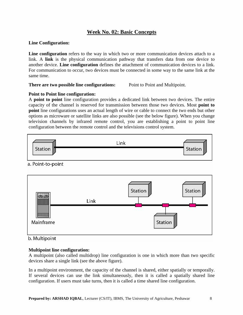
Line configuration refers to the way in which two or more communication devices attach to a link. A link is the physical communication pathway that transfers data from one device to another device. Line configuration defines the attachment of communication devices to a link. For communication to occur, two devices must be connected in some way to the same link at the same time.
There are two possible line configurations: Point to Point and Multipoint.
Point to Point line configuration:A point to point line configuration provides a dedicated link between two devices. The entire capacity of the channel is reserved for transmission between those two devices. Most point to point line configurations uses an actual length of wire or cable to connect the two ends but other options as microware or satellite links are also possible (see the below figure). When you change television channels by infrared remote control, you are establishing a point to point line configuration between the remote control and the televisions control system.
Multipoint line configuration:A multipoint (also called multidrop) line configuration is one in which more than two specific devices share a single link (see the above figure).
In a multipoint environment, the capacity of the channel is shared, either spatially or temporally. If several devices can use the link simultaneously, then it is called a spatially shared line configuration. If users must take turns, then it is called a time shared line configuration.

Prepared by: ARSHAD IQBAL, Lecturer (CS/IT), IBMS, The University of Agriculture, Peshawar 9
Network Topology:
The network topology is the shape or the physical connectivity of the network. Two or more devices connect to a link; two or more links form a topology. The topology of a network is the geometric representation of all the links and linking devices (usually called nodes) to each other.
There are four basic topologies: Bus, Star, Ring, and Mesh
Bus Topology:
• A bus topology is a multipoint line configuration. One long cable acts as a backbone to link all the devices in a network.
• In this topology, all the computers are connected in a series to one cable.
• Nodes are connected to the bus cable by drop-line and tap.• A drop-line is a connection running b/w the device and main cable.• A tap is a connector that either splices into the main cable to create a contact with the
metallic core.
Advantages: Easy installation and less cabling than other topologies.
Disadvantages: Difficult reconfiguration and fault (or break cable) isolation.
Prepared by: ARSHAD IQBAL, Lecturer (CS/IT), IBMS, The University of Agriculture, Peshawar 10
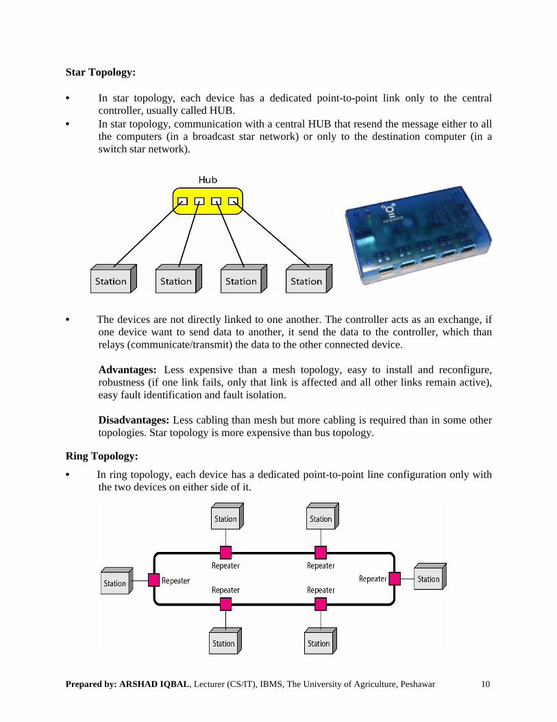
Star Topology:
• In star topology, each device has a dedicated point-to-point link only to the central controller, usually called HUB.
• In star topology, communication with a central HUB that resend the message either to all the computers (in a broadcast star network) or only to the destination computer (in a switch star network).
• The devices are not directly linked to one another. The controller acts as an exchange, if one device want to send data to another, it send the data to the controller, which than relays (communicate/transmit) the data to the other connected device.
Advantages: Less expensive than a mesh topology, easy to install and reconfigure, robustness (if one link fails, only that link is affected and all other links remain active), easy fault identification and fault isolation.
Disadvantages: Less cabling than mesh but more cabling is required than in some other topologies. Star topology is more expensive than bus topology.
Ring Topology:
• In ring topology, each device has a dedicated point-to-point line configuration only with the two devices on either side of it.
Prepared by: ARSHAD IQBAL, Lecturer (CS/IT), IBMS, The University of Agriculture, Peshawar 11
• A signal is passed along the ring in one direction, from device to device, until it reaches its destination.
• Each device in the ring incorporates the repeater, when a device receives a signal intended for another device; its repeater generates the bits and passes them along.
Advantages: Easy to install and reconfigure, fault isolation is simplified (easy, generally in a ring, a signal is circulating at all the times. If one device does not receive a signal within a specified period, it can issue an alarm. The alarm alerts the network operator to the problem and its location).
Disadvantages: Unidirectional traffic, and in a simple ring, a break in the ring (such as a disabled station) can disable the entire network. This weakness can be solved by using a dual ring or a switch capable of closing off the break.
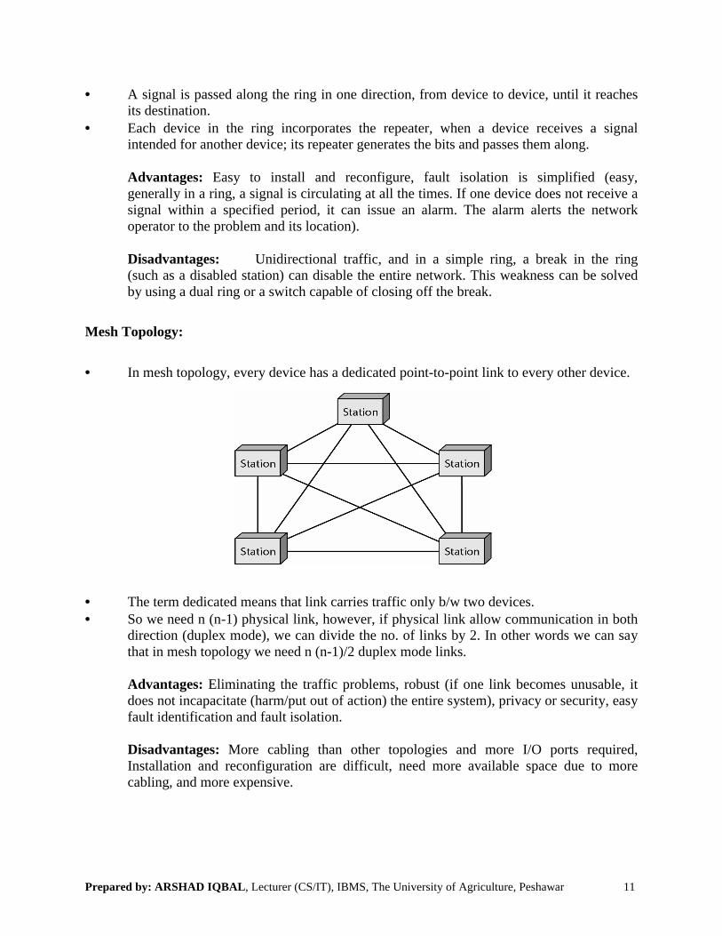
Mesh Topology:
• In mesh topology, every device has a dedicated point-to-point link to every other device.
• The term dedicated means that link carries traffic only b/w two devices.• So we need n (n-1) physical link, however, if physical link allow communication in both
direction (duplex mode), we can divide the no. of links by 2. In other words we can say that in mesh topology we need n (n-1)/2 duplex mode links.
Advantages: Eliminating the traffic problems, robust (if one link becomes unusable, it does not incapacitate (harm/put out of action) the entire system), privacy or security, easy fault identification and fault isolation.
Disadvantages: More cabling than other topologies and more I/O ports required, Installation and reconfiguration are difficult, need more available space due to more cabling, and more expensive.

Prepared by: ARSHAD IQBAL, Lecturer (CS/IT), IBMS, The University of Agriculture, Peshawar
Transmission Mode/Data Flow:The term transmission mode is used to define the direction of signal/data flow between two linked devices. Or the term transmission mode refers to the direction of information flow between two devices.
There are three types of transmission modes:
1. Simplex: - In simplex mode of data flow, communication can take place in only one direction (unidirectional, see below figurereceiver will always receive. Keyboards and traditional monitors are both examples of simplex devices. The keyboard can only introduce input; the monitor can only accept output. Another example is TV waves, we can watch different channels on TV but there is no need to send any type of signals from TV. Line
2. Half-Duplex: - A half-duplex system can transmit data in both direction, but same time, means only in one direction at a timeone computer can only send or receive, when one device completes a transmission, this device must “turn over” the medium to the other device so that this second device has turn to transmit. Walkie talkies and CB (Citizens Band) radios are both half duplex systems.
3. Full-Duplex: - This type of data flow allows a device to send & receive data simultaneously (see below figure).to simultaneously data transfer by providchannel. The full duplex mode is like a two way street with traffic flowing in both directions at the same time. In full duplex mode, signals going in either direction share the capacity of the link. One common example of full duplex communication is the tnetwork. When two people are communicating by a telephone line, both can talk and listen at the same time.
, Lecturer (CS/IT), IBMS, The University of Agriculture, Peshawar
The term transmission mode is used to define the direction of signal/data flow between two linked devices. Or the term transmission mode refers to the direction of information flow
There are three types of transmission modes: Simplex, Half Duplex, and Full Duplex.
In simplex mode of data flow, communication can take place in only one , see below figure). It means the sender will always send & the
Keyboards and traditional monitors are both examples of devices. The keyboard can only introduce input; the monitor can only accept
example is TV waves, we can watch different channels on TV but there is als from TV. Line printer is also an example of simplex
duplex system can transmit data in both direction, but not at the only in one direction at a time (see below figure). It means that at a time
can only send or receive, when one device completes a transmission, this device must “turn over” the medium to the other device so that this second device has turn
Walkie talkies and CB (Citizens Band) radios are both half duplex systems.
This type of data flow allows a device to send & receive data (see below figure). It is also called duplex. This system provides two
to simultaneously data transfer by providing each device with a separate communication The full duplex mode is like a two way street with traffic flowing in both
directions at the same time. In full duplex mode, signals going in either direction share the capacity of the link. One common example of full duplex communication is the tnetwork. When two people are communicating by a telephone line, both can talk and listen
12
The term transmission mode is used to define the direction of signal/data flow between two linked devices. Or the term transmission mode refers to the direction of information flow
, Half Duplex, and Full Duplex.
In simplex mode of data flow, communication can take place in only one . It means the sender will always send & the
Keyboards and traditional monitors are both examples of devices. The keyboard can only introduce input; the monitor can only accept
example is TV waves, we can watch different channels on TV but there is is also an example of simplex.
not at the . It means that at a time
can only send or receive, when one device completes a transmission, this device must “turn over” the medium to the other device so that this second device has turn
Walkie talkies and CB (Citizens Band) radios are both half duplex systems.
This type of data flow allows a device to send & receive data . This system provides two ways
communication The full duplex mode is like a two way street with traffic flowing in both
directions at the same time. In full duplex mode, signals going in either direction share the capacity of the link. One common example of full duplex communication is the telephone network. When two people are communicating by a telephone line, both can talk and listen

Prepared by: ARSHAD IQBAL, Lecturer (CS/IT), IBMS, The University of Agriculture, Peshawar 13
Week No. 03: Categories of Networks
Key Terms and Concepts:
What do you find on a network?
The following types of nodes may be found on a data communications system:
• Host: - A central computer which stores data and executes programs for terminals. It is usually associated with minicomputers or mainframes. It requires a multi- tasking, multi-user operating system such as UNIX.
• Terminal: - A computing device which is composed of a video screen and a keyboard. It allows a user to communicate with a host by typing information or commands. The host communicates with the terminal by updating the CRT (video). Terminals cannot execute programs.
• Workstation/Client: - The computer which use but do not provide network resources. Client also called Front End computer. OR A computer which takes advantage of the services provided by servers on the network. A workstation has its own processing capabilities since it is a full fledged computer with a microprocessor. “Client” often refers to the workstation’s operating system such as Windows, Macintosh or UNIX.
A network with two clients and one server.
• Server based Network/Client-Server Network: Server is a computer that provides network resources or services. Server also called Back End Computer. Server based network also called client-server network, containing Client & the server that support them. Examples include file server, print server or communication server.
• • • • •
Prepared by: ARSHAD IQBAL, Lecturer (CS/IT), IBMS, The University of Agriculture, Peshawar 14
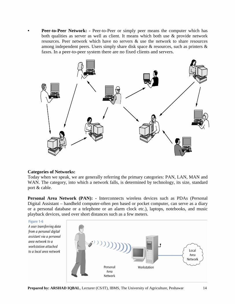
• Peer-to-Peer Network: - Peer-to-Peer or simply peer means the computer which has both qualities as server as well as client. It means which both use & provide network resources. Peer network which have no servers & use the network to share resources among independent peers. Users simply share disk space & resources, such as printers & faxes. In a peer-to-peer system there are no fixed clients and servers.
Categories of Networks:Today when we speak, we are generally referring the primary categories: PAN, LAN, MAN and WAN. The category, into which a network falls, is determined by technology, its size, standard port & cable.
Personal Area Network (PAN): - Interconnects wireless devices such as PDAs (Personal Digital Assistant – handheld computer-often pen based or pocket computer, can serve as a diary or a personal database or a telephone or an alarm clock etc.), laptops, notebooks, and music playback devices, used over short distances such as a few meters.
Prepared by: ARSHAD IQBAL, Lecturer (CS/IT), IBMS, The University of Agriculture, Peshawar 15
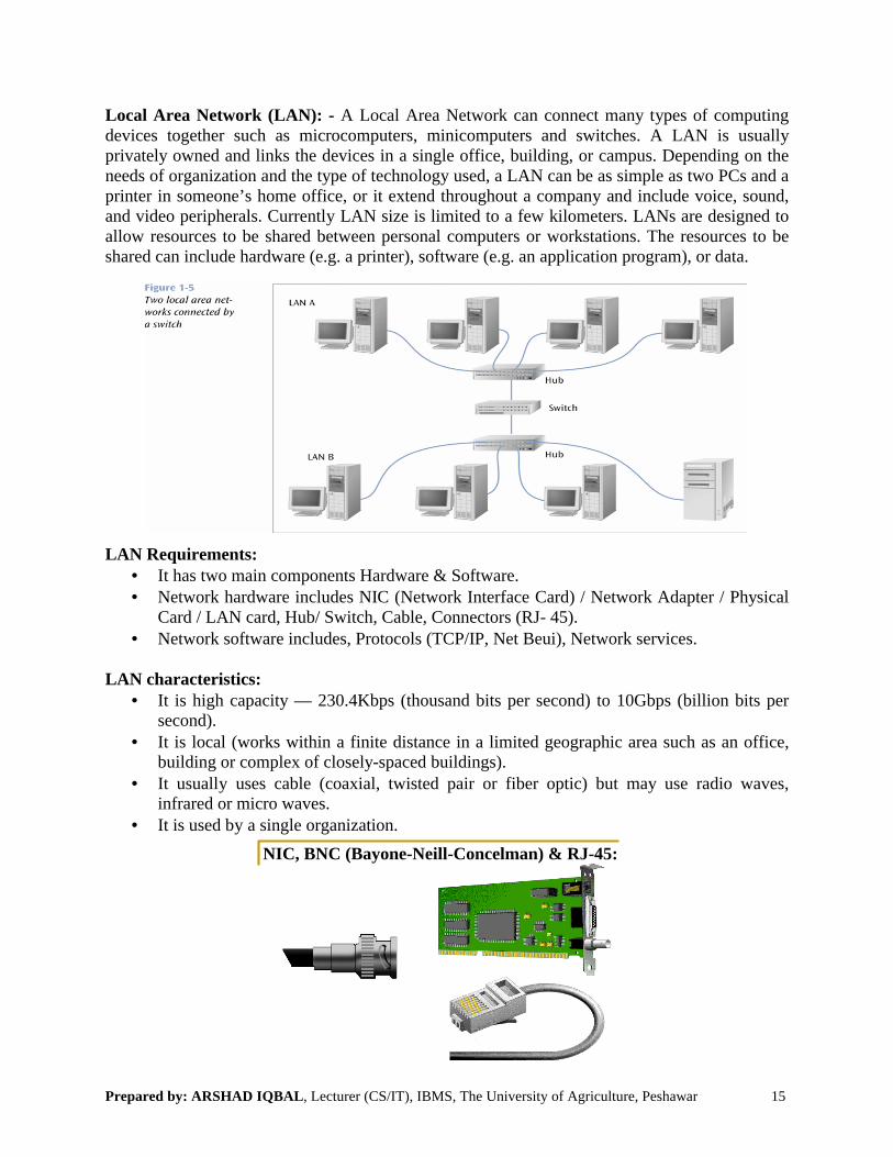
Local Area Network (LAN): - A Local Area Network can connect many types of computing devices together such as microcomputers, minicomputers and switches. A LAN is usually privately owned and links the devices in a single office, building, or campus. Depending on the needs of organization and the type of technology used, a LAN can be as simple as two PCs and a printer in someone’s home office, or it extend throughout a company and include voice, sound, and video peripherals. Currently LAN size is limited to a few kilometers. LANs are designed to allow resources to be shared between personal computers or workstations. The resources to be shared can include hardware (e.g. a printer), software (e.g. an application program), or data.
LAN Requirements:• It has two main components Hardware & Software.• Network hardware includes NIC (Network Interface Card) / Network Adapter / Physical
Card / LAN card, Hub/ Switch, Cable, Connectors (RJ- 45).• Network software includes, Protocols (TCP/IP, Net Beui), Network services.
LAN characteristics:• It is high capacity — 230.4Kbps (thousand bits per second) to 10Gbps (billion bits per
second).• It is local (works within a finite distance in a limited geographic area such as an office,
building or complex of closely-spaced buildings).• It usually uses cable (coaxial, twisted pair or fiber optic) but may use radio waves,
infrared or micro waves.• It is used by a single organization.
NIC, BNC (Bayone-Neill-Concelman) & RJ-45:

Prepared by: ARSHAD IQBAL, Lecturer (CS/IT), IBMS, The University of Agriculture, Peshawar
Metropolitan Area Network (MAN): city distances. OR It may be a single network such as a cable television network, or means of connecting a number of LANs into a larger network, so that resources may be shared LAN-to-LAN as well as device-to-device. the LANs in all of its offices throughout a city.
A metropolitan area network based on cable
A MAN may be wholly owned and operated by a private company, or it may be a service provided by a public company, such as a local telephone company.Many telephone companies provide a popular MAN service called Data Service (SMDS). It is a service for handling higharea network.
Wide Area Network (WAN): - The network between different cities, countries or in the world using WAN standard port & routing technology is called WAN.covers a large geographical area using communication channel that combines many types of media such as telephone lines, cables & radio waves.transmission of data, voice, image, and video information over large geographical areas that may comprise (contain/include/consist of)Internet is the world largest WAN. In contrast to LANs (which depend on their own hardware transmission), WANs may utilize public, leased, or private communication devices, usually in combinations, and can therefore span an unlimited number of miles. A WAN that is wholly owned and used by a single company is often referred to as an enterpris
WAN use data lines which belong to a third party service provider such as the telephone company. They require special interfaces to the data lines such as synchronous modems & routers. Routing technology is a crucial component of a WAN. Routersshould be sent in order that it arrives at its intended destination.
A stream of packets from sender to receiver
, Lecturer (CS/IT), IBMS, The University of Agriculture, Peshawar
): - A high speed (100 Mbps) network which spans (extend)It may be a single network such as a cable television network, or it
means of connecting a number of LANs into a larger network, so that resources may be shared device. For example, a company can use a MAN to connect
the LANs in all of its offices throughout a city.
olitan area network based on cable TV
may be wholly owned and operated by a private company, or it may be a service provided by a public company, such as a local telephone company.
a popular MAN service called Switched Multi-. It is a service for handling high-speed communication for metropolitan
The network between different cities, countries or in the world routing technology is called WAN. OR a WAN is a network that
covers a large geographical area using communication channel that combines many types of media such as telephone lines, cables & radio waves. A WAN provides long distance
oice, image, and video information over large geographical areas that may (contain/include/consist of) a country, a continent, or even the whole world.
In contrast to LANs (which depend on their own hardware transmission), WANs may utilize public, leased, or private communication devices, usually in combinations, and can therefore span an unlimited number of miles. A WAN that is wholly owned and used by a single company is often referred to as an enterprise network.
use data lines which belong to a third party service provider such as the telephone company. They require special interfaces to the data lines such as synchronous modems &
Routing technology is a crucial component of a WAN. Routers decide how a packet should be sent in order that it arrives at its intended destination.
A stream of packets from sender to receiver
16
s (extend)may be a
means of connecting a number of LANs into a larger network, so that resources may be shared For example, a company can use a MAN to connect
may be wholly owned and operated by a private company, or it may be a service
-megabit metropolitan
The network between different cities, countries or in the world WAN is a network that
covers a large geographical area using communication channel that combines many types of A WAN provides long distance
oice, image, and video information over large geographical areas that may a country, a continent, or even the whole world. The
In contrast to LANs (which depend on their own hardware for transmission), WANs may utilize public, leased, or private communication devices, usually in combinations, and can therefore span an unlimited number of miles. A WAN that is wholly
use data lines which belong to a third party service provider such as the telephone company. They require special interfaces to the data lines such as synchronous modems &
decide how a packet

Prepared by: ARSHAD IQBAL, Lecturer (CS/IT), IBMS, The University of Agriculture, Peshawar 17
Internet:• An internet (note the lowercase letter i) is two or more networks that can communicate with
each other. The term internet (lowercase i) should not be confused with the Internet (uppercase I). The first is a generic term used to mean an interconnection of networks. The second is the name of a specific World Wide Network.
• The most notable internet is called Internet (uppercase letter I), in which connect more than hundreds of thousands interconnected networks.
• Internet simply called “net” is a World Wide system of computer networks.• A network of networks in which user of any computer can get information from other
computer, if they have permission.• Every computer on the net has a unique Internet address or IP address (similar to telephone
address), which can be accessed any other computer by dialing to the other IP address.
History of Internet:• The extraordinary communication system “Internet” came into being in 1969.• In mid-1960, mainframe computers in research organization were stand-alone devices.
Computers from different manufacturers were unable to communicate with one another.• The Advanced Research Project Agency (ARPA) in the Department of Defense (DoD) was
interesting in finding a way to connect computers, so• In 1967, at an Association for Computing Machinery (ACM) meeting, ARPA presented its
ideas for ARPANET, a small network connected computes.• The basic purpose to create a network that allows the researchers of one university to able, to
talk or share their research to Researchers computers.• The network was designed to work without centralized control. This means if one portion of
network fails, the remaining portion will be able to route packets from sender to receiver through alternate path.
• The second benefit of ARPANET was that, messages could continue functionality, if one portion of network is destroyed in disaster or in military attack.
• Internet has linked numerous (many/several) LANs into huge network. The LANs and computer connected to internet is maintained by Internet Service Providers (ISPs), who sells internet services to people.
• Today most end users who want Internet connection, use the services of ISPs. There are International ISPs, National ISPs, Regional ISPs and Local ISPs.
• The International ISPs that connect nations together.• The National ISPs are backbone networks created and maintained by specialized companies,
like SprintLink, PSINet etc.• The Regional ISPs are smaller ISPs that are connected to one or more national ISPs.• The Local ISPs provide direct services to the end users.

Prepared by: ARSHAD IQBAL, Lecturer (CS/IT), IBMS, The University of Agriculture, Peshawar 18
Week No. 04: OSI Model
Network Models:
• The two best-known standards are the Open System Interconnection (OSI) Model andthe Internet Model or TCP/IP Model.
• The OSI reference model defines a seven-layered network, & the Internet model defines a five-layered network.
• OSI Reference model established in 1947, by the ISO (International Standard Organization).
• An ISO standard that covers all aspect of network communications is the OSI reference model.
• ISO is the organization and OSI is the model.• It was first introduced in the late 1970s.• The OSI reference model is not a protocol. It is a model for understanding and designing
a network architecture that is flexible, robust (healthy/strong) & interoperable (that is capable of working together without being specially configured to do so).
• The word reference means that OSI model is used with reference of two devices or networks. It is not for individual machine.
• The word open system allows any device. It means that this model is compatible (well-suited/well-matched/friendly) with all of the systems (IBM, Apple, Intel) and also compatible with software. When we send information using windows 2000, & the receiving device use window XP, it does not matter.
Layered Architecture:
• We use the concept of layers in our daily life. As an example, Let us consider two friends who communicate through postal mail. The process of sending a letter to a friend would be complex if there were no services available from the post office.

Prepared by: ARSHAD IQBAL, Lecturer (CS/IT), IBMS, The University of Agriculture, Peshawar 19
• OSI model is a layered approach for the designing of network systems that allows communication across all types of the computer systems.
• It consists of seven separate but related layers, each of which defines a segment of the process of moving information across a network.
• Each group of related task is called layer.
• A mnemonic (improving or developing the memory) for remembering the layers of OSI model is: “Please Do Not Touch Steve’s Pet Alligator” OR “All People Seem To Need Data Processing”
• In OSI model, within a single machine, each layer uses the services of the layer just below it. For example, layer 3 uses the services provided by layer 2 and provide services for layer 4.
• At the receiver point of view, the numbers are given to OSI model. • The four lower layer deals with the transmission of data. Establish connection to
exchange data. These layers don’t worry about the type of data; they send or receive. Simply deals with the task of sending it.
• The three upper layers define the communication with each other and with user.• Headers are added to the data at layers 6, 5, 4, 3, and 2. • Trailers are usually added only at layer 2.• At layer 1 the entire package is converted to a form that can be transferred to the
receiving machine.
Prepared by: ARSHAD IQBAL, Lecturer (CS/IT), IBMS, The University of Agriculture, Peshawar 20
Functions of layers in the OSI reference model:
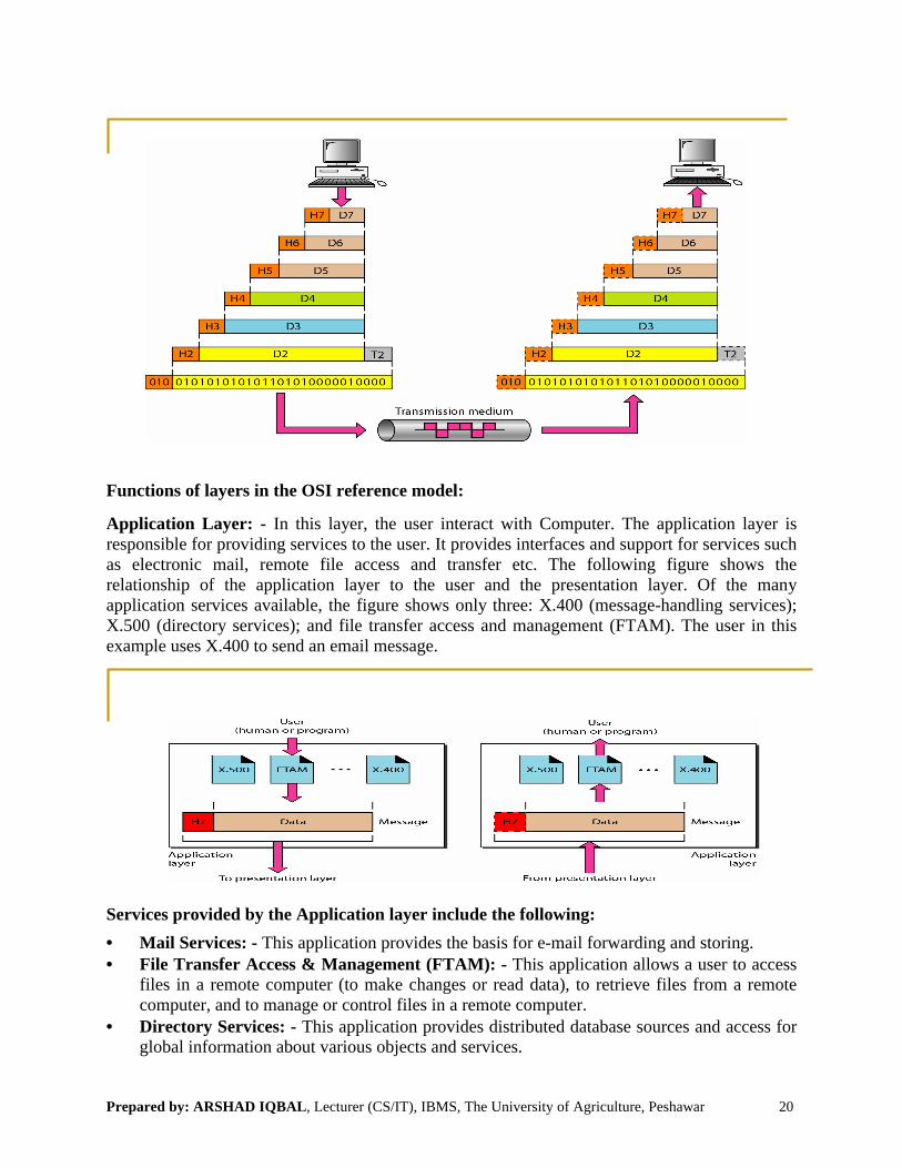
Application Layer: - In this layer, the user interact with Computer. The application layer is responsible for providing services to the user. It provides interfaces and support for services such as electronic mail, remote file access and transfer etc. The following figure shows the relationship of the application layer to the user and the presentation layer. Of the many application services available, the figure shows only three: X.400 (message-handling services); X.500 (directory services); and file transfer access and management (FTAM). The user in this example uses X.400 to send an email message.
Services provided by the Application layer include the following:
• Mail Services: - This application provides the basis for e-mail forwarding and storing.• File Transfer Access & Management (FTAM): - This application allows a user to access
files in a remote computer (to make changes or read data), to retrieve files from a remote computer, and to manage or control files in a remote computer.
• Directory Services: - This application provides distributed database sources and access for global information about various objects and services.

Prepared by: ARSHAD IQBAL, Lecturer (CS/IT), IBMS, The University of Agriculture, Peshawar 21
Presentation Layer: - The presentation layer is concerned with the syntax and semantics of the information exchanged between two systems.
The following figure shows the relationship of the presentation layer to session and application layers.
Services provided by the presentation layer include the following:
• Translation: - It provides a variety of a coding & conversion function that is applied to application layer data. It converts the data from the application into a common format, often called the “Canonical Representation”. So the presentation layer at the sender changes the information from its sender dependent format into a common format. The presentation layer at the receiving machine changes the common format into its receiver dependant format.
• Encryption: - It means that the presentation layers also encrypt & decrypt the information. Encryption means that the sender transforms the original information to another form and sends the resulting message out over the network. Decryption reverses the original process to transform the message back to its original form.
• Compression: - At the presentation layer, data is compressed to reduce the number of bits contained in the information; data compression is an important in the transmission of multimedia such as text, audio & video.
Session Layer: - The services provided by the first three layers (physical, data link, and network) are not sufficient for some processes. The session layer is the network dialog controller. It establishes, maintained & synchronizes the interaction between communicating systems.
The following figure shows the relationship of the session layer to the transport and presentationlayers.

Prepared by: ARSHAD IQBAL, Lecturer (CS/IT), IBMS, The University of Agriculture, Peshawar 22
Services provided by the Session Layer include the following:
• Dialog Control: - The session layer allows two systems to enter into a dialog (create a session). It allows the communication between two processes to take place in either half duplex (one way at a time) or full duplex mode (two ways at a time). For example, the dialog between a terminal connected to a mainframe can be half duplex.
• Synchronization: - The session layer allows a process to add checkpoints or synchronization points into a stream of data. For example, a system sending a file of 2000 pages. It inserts a checkpoint after every 100 pages to ensure that each 100 pages unit is received and acknowledged independently. If a crash happens during the transmission of page 523, then the only pages that need to be resent after system recovery are pages 501-523.
Transport Layer: - The transport layer is responsible for the delivery of a message from one process to another. Or the transport layer is responsible for source to destination (end to end) delivery of the entire message.
Whereas the network layer oversees (manage/supervise) end to end delivery of individual packets, it does not recognize any relationship between those packets. It treats each one independently, as though each piece belonged to a separate message. The transport layer, on the other hand, ensures that the whole message arrives intact (together /unbroken/undamaged) and in order, overseeing (managing/control/supervision) both error control and flow control at the source to destination level.
The following figure shows the relationship of the transport layer to the network and session layers.
Services provided by the Transport Layer include the following:
• Segmentation & Reassembly: - At the transport layer, a message is divided into segments (pieces of data) such as H E L L O) with each segment containing a sequence number. These numbers enable the transport layer to re-assemble the message correctly upon arriving at the destination and identify and replace packets that were lost in the transmission. The transport layer header includes a type of address called port address.

Prepared by: ARSHAD IQBAL, Lecturer (CS/IT), IBMS, The University of Agriculture, Peshawar
• Connection Control: - The transportoriented. A connection less transport layer treats edelivers it to the transport layer at the destination machine.layer makes a connection with the transport at the destination machine, first before delivering the packets. After all the data are transferred then the connection is terminated.
• Flow & Error Control: - Transport layer is responsible forHowever, flow control at this layer is performed end to end Error control at this layer is performed end to end rather than across a single link. The sending transport layer makes sure that the entire message arrives at the receiving transport layer without error (damage, loss. Or duplication). retransmission.
Network Layer: - In the network layerresponsible for the delivering of individual packets from the source device to destination device.The network layer ensures that each packet gets from its point of origin to its final destination.
If two systems are connected to the same link; there is usually no need for a network layer. However, if the two systems are attached to different networkthe networks, there is often a need for the network layer to accomplishout/do/complete) source to destination delivery.
The following figure shows the relationship of the network layer to the data link alayers.
, Lecturer (CS/IT), IBMS, The University of Agriculture, Peshawar
The transport layer can be either connectionless or connection A connection less transport layer treats each segment as an independent packet and
delivers it to the transport layer at the destination machine. The connection oriented transport layer makes a connection with the transport at the destination machine, first before delivering
the data are transferred then the connection is terminated.ransport layer is responsible for flow control & error control.
However, flow control at this layer is performed end to end rather than across a single link. l at this layer is performed end to end rather than across a single link. The
sending transport layer makes sure that the entire message arrives at the receiving transport layer without error (damage, loss. Or duplication). Error control is usually achieved through
In the network layer, the segments becomes packets. The network layer is responsible for the delivering of individual packets from the source device to destination device.The network layer ensures that each packet gets from its point of origin to its final destination.
two systems are connected to the same link; there is usually no need for a network layer. However, if the two systems are attached to different networks, with connecting devices between the networks, there is often a need for the network layer to accomplish (achieve/carry
source to destination delivery.
The following figure shows the relationship of the network layer to the data link and transport
23
less or connection ach segment as an independent packet and
The connection oriented transport layer makes a connection with the transport at the destination machine, first before delivering
flow control & error control. rather than across a single link.
l at this layer is performed end to end rather than across a single link. The sending transport layer makes sure that the entire message arrives at the receiving transport
d through
The network layer is responsible for the delivering of individual packets from the source device to destination device.The network layer ensures that each packet gets from its point of origin to its final destination.
two systems are connected to the same link; there is usually no need for a network layer. s, with connecting devices between
(achieve/carry
nd transport

Prepared by: ARSHAD IQBAL, Lecturer (CS/IT), IBMS, The University of Agriculture, Peshawar 24
Services provided by the Network Layer include the following:
• Logical Addressing: - The physical addressing implemented by the data link layer handles the addressing problem locally. If a packet passes the network boundary, we need another addressing system to help distinguish the source and destination systems. The network layer adds a header to the packet coming from the upper layer, which includes the logical addresses of the sender & receiver.
• Routing: - When independent networks or links are connected together to create an internetwork (a network of networks) or a large network, the connecting devices (called router or switches or gateways) route or switch the packets to their final destination.
Data Link Layer: - Data link layer is defines how data is transformed over a physical media. OR The data link layer is responsible for moving frames from one hop (node) to the next (node to node delivery).
The following figure shows the relationship of the data link layer to the network and physical layers.
Prepared by: ARSHAD IQBAL, Lecturer (CS/IT), IBMS, The University of Agriculture, Peshawar
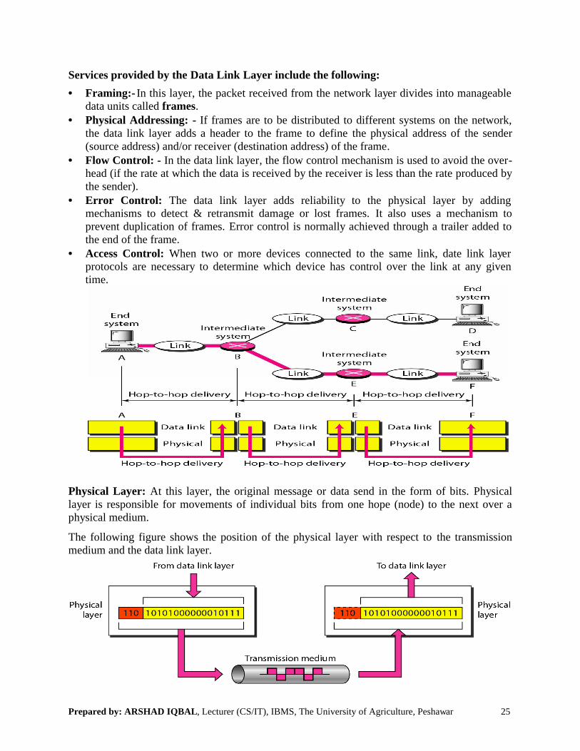
Services provided by the Data Link
• Framing:- In this layer, the packet received from the network layer divides into manageable data units called frames.
• Physical Addressing: - If frames are to be distributed to different systems on the network, the data link layer adds a header to the frame to define(source address) and/or receiver (destination address) of the frame
• Flow Control: - In the data link layerhead (if the rate at which the data is receivethe sender).
• Error Control: The data link layer adds reliability to the physical layer by adding mechanisms to detect & retransmit damage or lost frames. prevent duplication of frames. Error the end of the frame.
• Access Control: When two or more devices connected to the same link, date link layer protocols are necessary to determine which device has control over the link at any given time.
Physical Layer: At this layer, the original message or data send in the form of bits.layer is responsible for movements of individual bitsphysical medium.
The following figure shows the position of the physical layer with respect tomedium and the data link layer.
, Lecturer (CS/IT), IBMS, The University of Agriculture, Peshawar
Layer include the following:
the packet received from the network layer divides into manageable
If frames are to be distributed to different systems on the network, layer adds a header to the frame to define the physical address of the sender
(destination address) of the frame.In the data link layer, the flow control mechanism is used to avoid the over
head (if the rate at which the data is received by the receiver is less than the rate produced by
The data link layer adds reliability to the physical layer by adding to detect & retransmit damage or lost frames. It also uses a mechanism to
Error control is normally achieved through a trailer added to
When two or more devices connected to the same link, date link layer protocols are necessary to determine which device has control over the link at any given
the original message or data send in the form of bits.layer is responsible for movements of individual bits from one hope (node) to the next over a
The following figure shows the position of the physical layer with respect to the transmission
25
the packet received from the network layer divides into manageable
If frames are to be distributed to different systems on the network, the sender
the flow control mechanism is used to avoid the over-produced by
The data link layer adds reliability to the physical layer by adding It also uses a mechanism to
control is normally achieved through a trailer added to
When two or more devices connected to the same link, date link layer protocols are necessary to determine which device has control over the link at any given
Physical rom one hope (node) to the next over a
the transmission
Prepared by: ARSHAD IQBAL, Lecturer (CS/IT), IBMS, The University of Agriculture, Peshawar 26
Services provided by the Physical Layer include the following:
• Physical Characteristics of Interfaces & Media: - The physical layer defines the characteristics of the interface between the devices and the transmission medium. It also defines the type of transmission medium.
• Representation of bits: The physical layer data consist of a steam of bits (sequence of 0s and 1s). To be transmitted, bits must be encoded into signals. The physical layer defines the type of encoding (how 0s and 1s are changed to signals).
• Data Rate: - The physical layer defines data rate (the No. Of bps)• Synchronization of bits: The sender and receiver must be synchronized (coordinate) at the
bit level.• Line Configuration: The physical layer is concerned with the connection of devices to the
media. In a point-to-point configuration two devices are connected through a dedicated link. In a multipoint configuration, a link is shared among several devices.
• Physical Topology: - The physical topology defines that how devices are connected to make a network. Devices can be connected using a mesh topology, a star topology, a ring topology or a bus topology.
• Transmission mode: The physical layer also defines the direction of transmission between two devices: Simplex, Half duplex, or Full duplex.
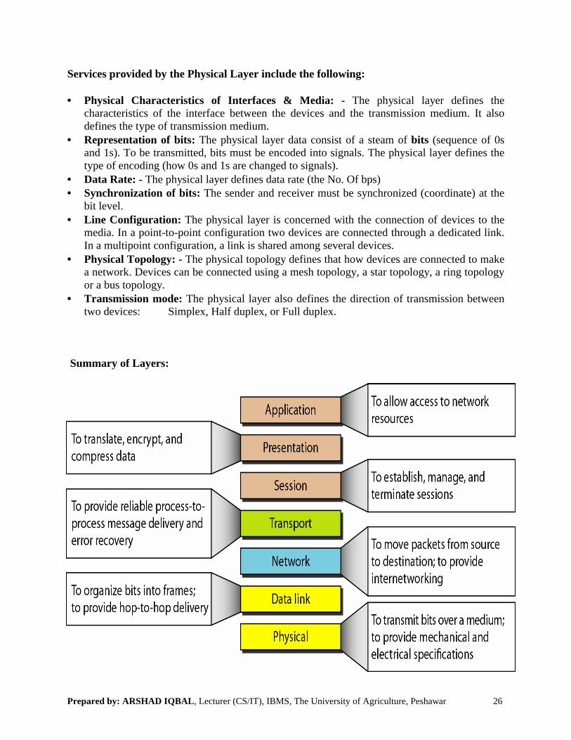
Summary of Layers:

Prepared by: ARSHAD IQBAL, Lecturer (CS/IT), IBMS, The University of Agriculture, Peshawar 27
Week No. 05 & 06: Transmission Control Protocol/Internet Protocol
TCP/IP Protocol Suite:
• TCP/IP is called a family of protocols. • The TCP/IP protocol suite was developed before to the OSI model. Therefore the layers
in the TCP/IP protocol suite do not exactly match to those in the OSI model. The original TCP/IP protocol suite was defined as having four layers.
i. Host to network layerii. Internet layeriii. Transport layeriv. Application layer
• Host to Network layer of the TCP/IP protocol suite is equivalent to the combination of physical and Data link layers of the OSI model.
• The internet layer is equivalent to the network layer of the OSI model.• At transport layer, TCP/IP defines three protocols: TCP, UDP, and SCTP.• And the application layer is roughly doing the job of the session, presentation &
application layers of the OSI model.
• However, when TCP/IP is compared to OSI, we can say that the TCP/IP protocol suite is made of five layers: Physical, Data Link, Network, Transport, and Application.
• So we assume that the TCP/IP protocol suite is made of five layers.
Prepared by: ARSHAD IQBAL, Lecturer (CS/IT), IBMS, The University of Agriculture, Peshawar 28
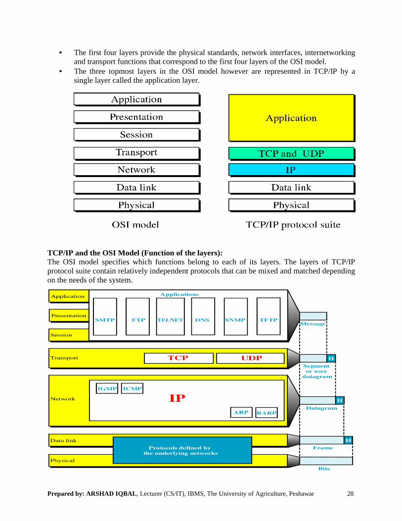
• The first four layers provide the physical standards, network interfaces, internetworking and transport functions that correspond to the first four layers of the OSI model.
• The three topmost layers in the OSI model however are represented in TCP/IP by a single layer called the application layer.
TCP/IP and the OSI Model (Function of the layers):The OSI model specifies which functions belong to each of its layers. The layers of TCP/IP protocol suite contain relatively independent protocols that can be mixed and matched depending on the needs of the system.

Prepared by: ARSHAD IQBAL, Lecturer (CS/IT), IBMS, The University of Agriculture, Peshawar 29
Physical & Data link layers: - At the physical & data link layers, TCP/IP does not define any specific protocol. It supports all the standard & proprietary protocol (owned by a company). A network in a TCP/IP Inter-network can be a LAN or a WAN.
Network layers: - At the network layer, the main protocol define by TCP/IP is the Internet protocol (IP). There are also some other protocols that support data movement in this layer such as ARP, RARP, ICMP, & IGMP.
• Internet Protocol: - IP is responsible for moving the packets (called datagram’s),assemble (bring together/collect) by either TCP/UDP across network.
• It uses a set of unique address for every device on the network to determine routing & destinations.
• It is unreliable & connection less protocol but provides a best effort delivery service. The term best effort means that IP provides no error checking or tracking.
• IP does not keep track of the routes and has no facility for reordering datagram’s once they arrive at their destination.
• Datagram: - Packets in the network or internet layer is called datagram's. The following figure shows the IP datagram format.
• A datagram is a variable length packet (up to 65,536 bytes) consisting of two parts: header & data.
• The header can be from 20 to 60 bytes and contains information essential(necessary/important/crucial) to routing and delivery.
• A brief description of each field:• Version: - The first field defines the version of the IP protocol. Currently the version is
4 (IPv4). Its size is 4 bits.

Prepared by: ARSHAD IQBAL, Lecturer (CS/IT), IBMS, The University of Agriculture, Peshawar 30
• Header Length (HLEN): - The HLEN field defines the length of the header in multiple of four bytes. This field is needed because the length of the header is variable (20-60 bytes). The four bits can represent a number b/w 0 and 15, which, when multiplied by 4, gives a maximum of 60 bytes.
• Service type: - This field defines how the datagram should be handled. It includes bits that define the priority of the datagram. It also contains bits that specify the type of service the sender desires such as the level of throughput, Reliability, and delay.
• Total length: - This field defines the total length of the IP datagram. It is a two-byte (16-bit) field and can define up to 65,536 bytes.
• Identification: - This field is used in fragmentation. A datagram, when passing through different networks, may be divided into fragments to match the network frame size. When this happens, each fragment is identified with a sequence number in this field.
• Flags: - The bits in the flags field deal with fragmentation (the datagram can or can’t be fragmented, can be the first or last fragment)
• Fragmentation Offset: - It shows the relative position of this fragment with respect to the whole datagram. It is a pointer that shows the offset (balance) of the data in the original datagram (if it is fragmented).
• Time to live: - This field defines the number of hops which a datagram can travel before it is discarded. The source host, when it creates the datagram, sets this field to an initial value. Then as the datagram travels through the internet, router by router, each router decrements this value by 1. If this value becomes 0 before the datagram reaches to its final destination, the datagram is discarded. This prevents a datagram from going back and forward forever between routers.
• Protocol: - This field defines which upper layer protocol data are encapsulated in the datagram (TCP, UDP, ICMP etc).
• Header checksum: - This is a 16-bit field used to check the integrity(honesty/truth/reliability) of the header, not the rest of the packet.
• Source address: - The source address field is a four byte (32-bits) Internet address. It identifies the original source of the datagram’s.
• Destination address: - The destination address is a four byte (32-bits) Internet address. It identifies the final destination of datagram.
• Options: - This field gives more functionality to the IP datagram. It can carry fields that control routing, timing, management, and alignment.
• Other supporting protocols on the Internet or Network Layer:• ARP (Address Resolution Protocol): - It is used to associate a logical address (IP) with
a physical address. On a typical network such as LAN, each device on a link is identified by physical address. It is used to find the physical address of the node when its Internet address (IP) is known.
• To determine a destination address for a datagram, the ARP cache table is checked. If address is not in the table, ARP send a broadcast looking for the destination, every node on the network receive the broadcast.
Prepared by: ARSHAD IQBAL, Lecturer (CS/IT), IBMS, The University of Agriculture, Peshawar
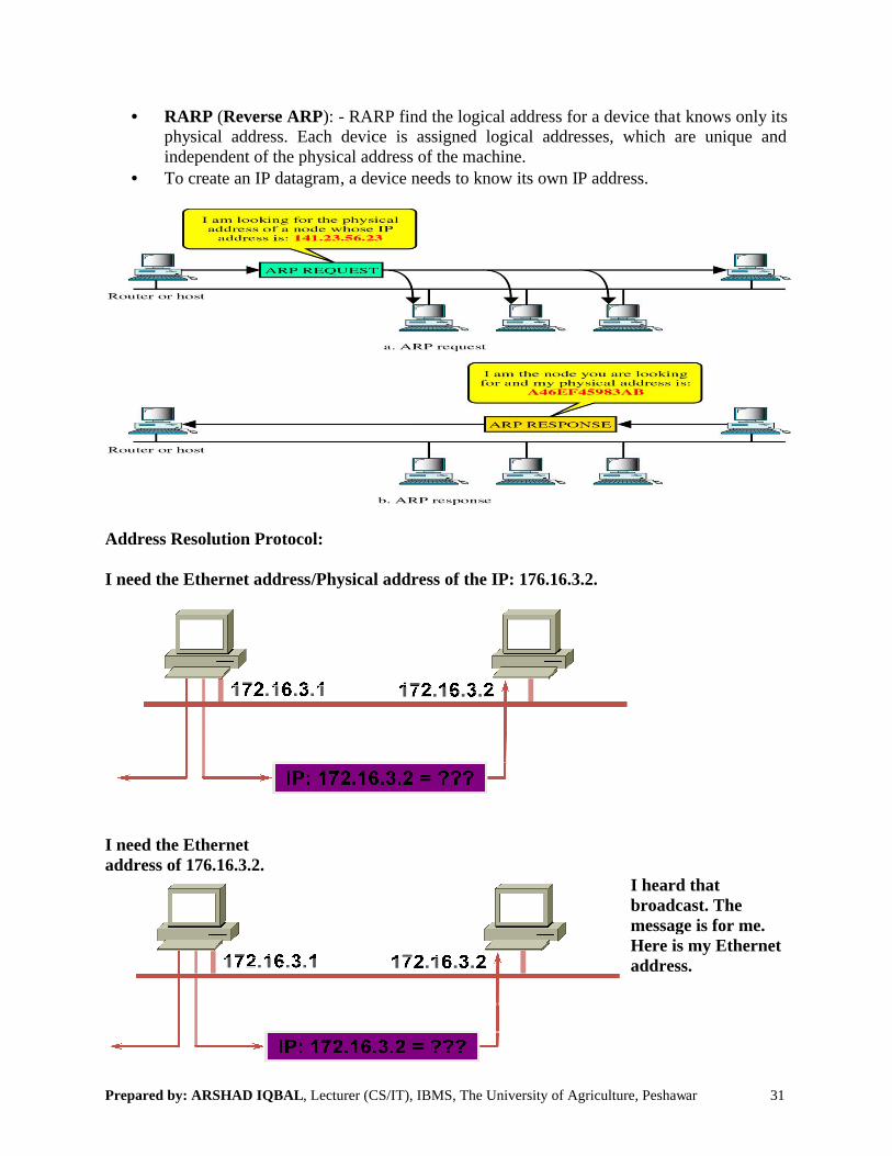
• RARP (Reverse ARP): - RARP find the logical address for a device thaphysical address. Each device is assigned logical addresses, which are unique and independent of the physical address of the machine.
• To create an IP datagram, a device needs
Address Resolution Protocol:
I need the Ethernet address/Physical
I need the Ethernet address of 176.16.3.2.
, Lecturer (CS/IT), IBMS, The University of Agriculture, Peshawar
RARP find the logical address for a device that knows only its physical address. Each device is assigned logical addresses, which are unique and independent of the physical address of the machine.
a device needs to know its own IP address.
/Physical address of the IP: 176.16.3.2.
I heard that broadcast. The message is for me. Here is my Ethernet address.
31
t knows only its physical address. Each device is assigned logical addresses, which are unique and
I heard that broadcast. The message is for me. Here is my Ethernet
Prepared by: ARSHAD IQBAL, Lecturer (CS/IT), IBMS, The University of Agriculture, Peshawar
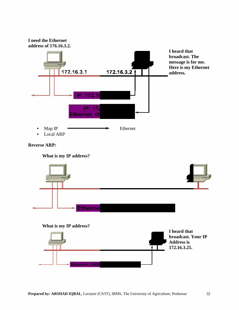
I need the Ethernet address of 176.16.3.2.
• Map IP • Local ARP
Reverse ARP:
What is my IP address?
What is my IP address?
, Lecturer (CS/IT), IBMS, The University of Agriculture, Peshawar
I heard that broadcast. The message is for me. Here is my Ethernet address.
Ethernet
I heard that broadcast. Your IP Address is 172.16.3.25.
32
I heard that broadcast. The message is for me. Here is my Ethernet
I heard that broadcast. Your IP
Prepared by: ARSHAD IQBAL, Lecturer (CS/IT), IBMS, The University of Agriculture, Peshawar
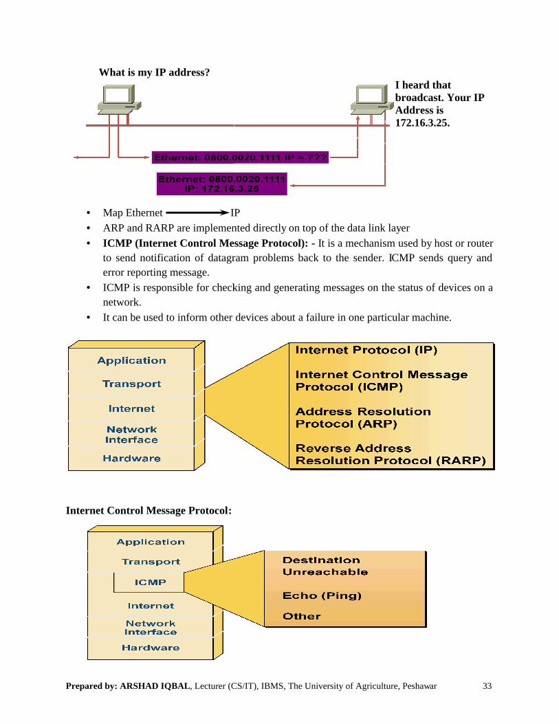
What is my IP address?
• Map Ethernet IP
• ARP and RARP are implemented directly on top of the data link layer
• ICMP (Internet Control Message Protocol):
to send notification of datagram problems back to the sender. ICMP sends query and
error reporting message.
• ICMP is responsible for checking and generating messages on the status of devices on a
network.
• It can be used to inform other devices about
Internet Control Message Protocol:
, Lecturer (CS/IT), IBMS, The University of Agriculture, Peshawar
I heard that broadcast. Your IP Address is 172.16.3.25.
IP
ARP and RARP are implemented directly on top of the data link layer
(Internet Control Message Protocol): - It is a mechanism used by host or router
to send notification of datagram problems back to the sender. ICMP sends query and
ICMP is responsible for checking and generating messages on the status of devices on a
used to inform other devices about a failure in one particular machine.
33
I heard that broadcast. Your IP
It is a mechanism used by host or router
to send notification of datagram problems back to the sender. ICMP sends query and
ICMP is responsible for checking and generating messages on the status of devices on a
a failure in one particular machine.
Prepared by: ARSHAD IQBAL, Lecturer (CS/IT), IBMS, The University of Agriculture, Peshawar
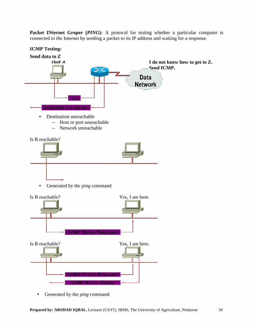
Packet INternet Groper (PING): A protocol for testing whether a particular computer is connected to the Internet by sending a
ICMP Testing:
Send data to Z
• Destination unreachable– Host or port unreachable– Network unreachable
Is B reachable?
• Generated by the ping command
Is B reachable?
Is B reachable?
• Generated by the ping command
, Lecturer (CS/IT), IBMS, The University of Agriculture, Peshawar
A protocol for testing whether a particular computer is connected to the Internet by sending a packet to its IP address and waiting for a response.
I do not know how to get to Z.Send ICMP.
Host or port unreachable
command
Yes, I am here.
Yes, I am here.
command
34
A protocol for testing whether a particular computer is packet to its IP address and waiting for a response.
I do not know how to get to Z.

Prepared by: ARSHAD IQBAL, Lecturer (CS/IT), IBMS, The University of Agriculture, Peshawar 35
• IGMP (Internet Group Message Protocol): - It is used to facilitate the simultaneous transmission of a message to a group of recipients.
• IGMP is not a multicasting routing protocol. It is a protocol that manages group membership. In any network, there are one or more multi-cast routers that distribute multicast packets to host or other routers.
• The IGMP protocol gives the multicast routers information about the membership status of hosts (routers) connected to the network.
• IGMP is a group management protocol. It helps a multicast router, create and update a list of loyal (devoted) member related to each router interface.
Transport Layer: - Traditionally the transport layer was represented in TCP/IP by two protocols: TCP & UDP.
• UDP & TCP are transport layer protocols responsible for the delivery of a message from a process (running program) to another process.
• A new transport layer protocol, SCTP (Stream Control Transmission Protocol), has been advised to meet the needs of some newer applications.
• UDP (User Datagram Protocol): - It is connection-less, unreliable protocol. • It is a process-to-process (using port no.) protocol that adds only port addresses,
checksum, error control, and length information to the data from upper layer. UDP packets, called user datagram, have a fixed size of header of 8-bytes.
• If a process wants to send a small message, it does not care much about reliability. It can use UDP, sending a small message by using UDP, takes much less interaction between the sender and receiver than TCP or SCTP.
UDP Datagram Format:
• A brief description of its field:• Source Port Address: - It is the address of the application program that has created the
message.• Destination Address: - It is the address of the application program that will receive the
message.• Total Length: - This field defines the total length of the user datagram in bytes.• Checksum: - The checksum is a 16-bits field used in error detection.

Prepared by: ARSHAD IQBAL, Lecturer (CS/IT), IBMS, The University of Agriculture, Peshawar
• TCP (Transmission Control Protocol):applications.
• TCP is reliable stream transport protocol. The term stream in this context means connection oriented. A connection must be established between both ends of a transmission before either can transmit data.
• At the sending end of each transmissioncalled segment. Each segment includetogether with an acknowledgement no; for the segment received.
• Segments are carried across the internet inside of IP• At the receiving end, TCP collects each datagram as it comes in re
transmission based on sequence no.
• A brief description of each field:• Source Port Address: - It defines the application program in the source computer.• Destination Port Address: -
computer. • Sequence Number: - This field shows the position of the data in the original data stream.• Acknowledgement Number:
from the other communication device.• Header Length (HLEN): - This field indicates the number
header. The four bit can define the number up to 15. This multiplied by 4 (15x4) to give the total number of bytes in the header.
• Reserved: - A six bit field is reserved for future use.
, Lecturer (CS/IT), IBMS, The University of Agriculture, Peshawar
(Transmission Control Protocol): TCP provides full transport layer services to
TCP is reliable stream transport protocol. The term stream in this context means connection must be established between both ends of a
transmission before either can transmit data.At the sending end of each transmission, TCP divides a stream of data into smaller units
Each segment includes a sequence no; of re-ordering after receipt, together with an acknowledgement no; for the segment received. Segments are carried across the internet inside of IP-Datagram’s.At the receiving end, TCP collects each datagram as it comes in re-orders the
ansmission based on sequence no.
description of each field:It defines the application program in the source computer.
- It defines the application program in the destination
This field shows the position of the data in the original data stream.: - This number is used to acknowledge the receipt of data
from the other communication device.This field indicates the number of 32-bit words in the TCP
header. The four bit can define the number up to 15. This multiplied by 4 (15x4) to give the total number of bytes in the header.
A six bit field is reserved for future use.
36
provides full transport layer services to
TCP is reliable stream transport protocol. The term stream in this context means connection must be established between both ends of a
TCP divides a stream of data into smaller units ordering after receipt,
orders the
It defines the application program in the source computer.It defines the application program in the destination
This field shows the position of the data in the original data stream.This number is used to acknowledge the receipt of data
bit words in the TCP header. The four bit can define the number up to 15. This multiplied by 4 (15x4) to give

Prepared by: ARSHAD IQBAL, Lecturer (CS/IT), IBMS, The University of Agriculture, Peshawar
• Control: - Each bit of the six-bit• URG: - The urgent bit, when set, then the urgent pointer field indicates
in the segment are urgent.• ACK: - The acknowledgment bit
acknowledgement number.• PSH: - The push bit is used to inform the sender that a higher • RST: - The reset bit is used to reset the connection when there is confusion in the
sequence number.• SYN: - The synchronization bit
three types of segments: connection request, connection confirmation, and confirmation acknowledgement.
• FIN: - The finish bit is used in connection termination.• Window size: - A window is 16• Checksum: - The checksum is 16• Urgent pointer: - This is the last required field in the header. Its value is valid only if the
URG bit in control field is set.• Option & Padding: - The remainder of the TCP header
, Lecturer (CS/IT), IBMS, The University of Agriculture, Peshawar
bit, controls field functions individually and independent, when set, then the urgent pointer field indicates that the data
acknowledgment bit, when set, then validate (authenticate/confirm).
is used to inform the sender that a higher throughput is needed.is used to reset the connection when there is confusion in the
synchronization bit is used for sequence number synchronization in three types of segments: connection request, connection confirmation, and confirmation acknowledgement.
is used in connection termination.A window is 16-bit field that define the sliding window.
The checksum is 16-bit field used in error detection.This is the last required field in the header. Its value is valid only if the
The remainder of the TCP header defines the optional field.
37
field functions individually and independently.that the data
(authenticate/confirm) the
is needed.is used to reset the connection when there is confusion in the
uence number synchronization in three types of segments: connection request, connection confirmation, and
This is the last required field in the header. Its value is valid only if the
defines the optional field.

Prepared by: ARSHAD IQBAL, Lecturer (CS/IT), IBMS, The University of Agriculture, Peshawar 38
• SCTP (Stream Control Transmission Protocol): - SCTP provides support for newer applications such as voice over the internet.
• It is transport layer protocol that combines the best features of UDP & TCP.• It preserves the message boundaries and at the same time detects lost data, duplicate data,
and out of order data. It also has congestion control flow control mechanism. • When we are sending real-time data such as audio or video, SCTP allows multi-stream
services in each connection; which is called association in SCTP terminology. If one of the streams is blocked, the other stream can still deliver their data.
• The idea is similar to multiple lanes on a highway each lane can be used for a different type of traffic e.g. One lane can be used for regular traffic another for car pools. If the traffic is blocked for regular vehicles, car pool vehicles can still reach their destination.
Application Layer: - The application layer in TCP/IP is equivalent to the combination of session, presentation application layer in the OSI model.
• The protocols defined at this layer are: • TELENT: - TELENT is an abbreviation for TErminaL NETwork. • It is the standard TCP/IP protocol for virtual terminal services as proposed by the ISO. • TELENT enables the establishment of a connection to a remote system in such a way that
the local terminal appears to be a terminal at the remote system.• TELNET is a general purpose client-server application program.• FTP (File transfer Protocol): - FTP is the standard mechanism provide by TCP/IP for a
copying a file from one host to another. Although transferring files from one system to another seems simple and straightforward.
• FTP establishes two connections between the hosts. • One connection is used from data transfer, the other for control information (command
and responses). • Separation of commands & data transfer makes FTP more efficient. • FTP uses the service of TCP. It needs two TCP connections. FTP uses two well-known
TCP ports: Port 21 is used for control connection & Port 20 for data connection.
• Once the connection to a remote machine has been established, FTP enables you to copy one or more files to your machine. (The term transfer implies that the file is moved from one system to another but the original is not affected. Files are copied).

Prepared by: ARSHAD IQBAL, Lecturer (CS/IT), IBMS, The University of Agriculture, Peshawar 39
• SMTP (Simple Mail Transfer Protocol): - SMTP is used for transferring electronic mail. SMTP completely transparent to the user. Behind the sense, SMTP connects to remote machines and transfer mail message much like FTP transfer files. Users are almost never aware of SMTP working, and few system administrators have to bother(trouble/difficult/problem) with it. SMTP is mostly trouble-free protocol and is in very wide use.
• Kerberos: - Kerberos is a widely supported security protocol. Kerberos uses a special application called an authentication server, to validate passwords and encryption schemes. Kerberos is one of the more secure encryption systems used in communication and is quite common in UNIX.
• DNS (Domain Name System): DNS server translate symbolic machine name (such as www.uoregon.edu) into numerical IP address. Or DNS provides translation between host name and IP address.
• For example, www.uoregon.edu is translated by DNS to 128.223.142.13. Symbolic names are a great convenience because they are easier to remember than numerical addresses.
• Domain name is a user friendly name and which identifies one or more IP addresses. Domain names are used in URLS to identify a particular webpage.
• Uniform Resource Locator (URL) is a fancy (picture/imagine/consider) term for the address of a World Wide Web page or other resource.
• SNMP (Simple Network Management Protocol): SNMP provides status of messages and problem reports across a network to an administrator, SNMP uses user data-gram protocol as a transport mechanism,. SNMP employ (use) slightly different terms from TCP/IP, working with manager and agents instead of client and servers. An agent provides information about a device, where a manger communicate, across a network with agents.
• TFTP (Trivial File Transfer Protocol): TFTP is very simple, un-sophisticated file transfer protocol that lacks security. It uses UDP as a transport protocol, TFTP performs the same task as FTP, but uses a different transport protocols.

Prepared by: ARSHAD IQBAL, Lecturer (CS/IT), IBMS, The University of Agriculture, Peshawar
Addressing:
Four levels of addresses are used in an internet employingPhysical (Link) addresses, Logical (IP) addresses, Port addresses & specific addresses
Physical address: - It is also known as link address. It is included in the frame used by the data link layer. It is the lowest level address.
• The physical addresses have authority over the network (LAN & WAN). • Ethernet uses a 48-bit (6-byte) physical address written as 12 hexade
byte (2 hexadecimal digits) is separated by a colon.• The first 6 Hexa-decimal digits of a Mac address contain a manufacturer, identification
(vender code) also known as the digit are given by each vender and often
• On most LAN interface card the MAC address is LAN communication.
, Lecturer (CS/IT), IBMS, The University of Agriculture, Peshawar
Four levels of addresses are used in an internet employing (using) the TCP/IP protocolsPhysical (Link) addresses, Logical (IP) addresses, Port addresses & specific addresses
also known as link address. It is included in the frame used by the data link layer. It is the lowest level address.
The physical addresses have authority over the network (LAN & WAN). byte) physical address written as 12 hexadecimal digits; every
byte (2 hexadecimal digits) is separated by a colon.decimal digits of a Mac address contain a manufacturer, identification
(vender code) also known as the Organizationally Unique Identifier (OUI). The last 6 en by each vender and often represents the interface serial no.
On most LAN interface card the MAC address is burned into ROM. It is only used for
40
the TCP/IP protocols: Physical (Link) addresses, Logical (IP) addresses, Port addresses & specific addresses .
also known as link address. It is included in the frame used by the
cimal digits; every
decimal digits of a Mac address contain a manufacturer, identification (OUI). The last 6
It is only used for
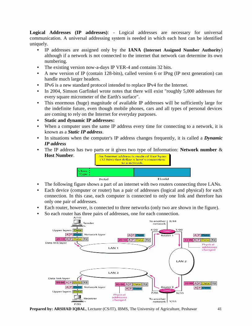
Prepared by: ARSHAD IQBAL, Lecturer (CS/IT), IBMS, The University of Agriculture, Peshawar
Logical Addresses (IP addresses)communication. A universal addressing system is needed in which each host can be identified uniquely.
• IP addresses are assigned only by although if a network is not connected to the internet that network can determine its own numbering.
• The existing version now-a-days IP VER• A new version of IP (contain 128
handle much larger headers.• IPv6 is a new standard protocol intended to replace IPv4 for the Internet. • In 2004, Simson Garfinkel wrote notes that there will exist "roughly 5,000 addresses for
every square micrometer of the Earth's surface".• This enormous (huge) magnitude of available IP addresses will be sufficiently large for
the indefinite future, even though mobile phones, cars and all types of personal devices are coming to rely on the Internet for everyday purposes.
• Static and dynamic IP addresses• When a computer uses the same IP address every time for
known as a Static IP address.• In situations when the computer's IP address changes freq
IP address• The IP address has two parts or it give
Host Number.
• The following figure shows a part of an internet with two routers connecting three LANs. • Each device (computer or router) has a pair of addresses (logical and physical) for each
connection. In this case, each computer is connected to only one link and therefore has only one pair of addresses.
• Each router, however, is connected to three networks (only two are shown in the figure). • So each router has three pairs of addresses, one for each connection.
, Lecturer (CS/IT), IBMS, The University of Agriculture, Peshawar
Logical Addresses (IP addresses): - Logical addresses are necessary for universal A universal addressing system is needed in which each host can be identified
IP addresses are assigned only by the IANA (Internet Assigned Number Authorityalthough if a network is not connected to the internet that network can determine its own
days IP VER-4 and contains 32 bits.A new version of IP (contain 128-bits), called version 6 or IPng (IP next generation) can
IPv6 is a new standard protocol intended to replace IPv4 for the Internet. In 2004, Simson Garfinkel wrote notes that there will exist "roughly 5,000 addresses for every square micrometer of the Earth's surface".
magnitude of available IP addresses will be sufficiently large for the indefinite future, even though mobile phones, cars and all types of personal devices are coming to rely on the Internet for everyday purposes. Static and dynamic IP addresses:
e same IP address every time for connecting to a network, it is
In situations when the computer's IP address changes frequently, it is called a
The IP address has two parts or it gives two type of Information: Network number
figure shows a part of an internet with two routers connecting three LANs. Each device (computer or router) has a pair of addresses (logical and physical) for each
In this case, each computer is connected to only one link and therefore has
Each router, however, is connected to three networks (only two are shown in the figure). So each router has three pairs of addresses, one for each connection.
41
ses are necessary for universal A universal addressing system is needed in which each host can be identified
Internet Assigned Number Authority)although if a network is not connected to the internet that network can determine its own
bits), called version 6 or IPng (IP next generation) can
In 2004, Simson Garfinkel wrote notes that there will exist "roughly 5,000 addresses for
magnitude of available IP addresses will be sufficiently large for the indefinite future, even though mobile phones, cars and all types of personal devices
network, it is
it is called a Dynamic
Network number &
figure shows a part of an internet with two routers connecting three LANs. Each device (computer or router) has a pair of addresses (logical and physical) for each
In this case, each computer is connected to only one link and therefore has
Each router, however, is connected to three networks (only two are shown in the figure).

Prepared by: ARSHAD IQBAL, Lecturer (CS/IT), IBMS, The University of Agriculture, Peshawar
Class A:
• This address include the following:• The first bit of Netid is 0.• Range of the network members • Number of Possible Networks, 127 (1• Number of possible values in the host portion: 2
of host bits.• Note: such addresses where all the host bit
that we can’t use, e.g. 10.0.0.0 the broadcast addresses, which we can’t use. e.g.
, Lecturer (CS/IT), IBMS, The University of Agriculture, Peshawar
This address include the following:
Range of the network members 0.0.0.0 to 127.255.255.255Number of Possible Networks, 127 (1-126 usable, 127 is reserved).Number of possible values in the host portion: 2n = 224 = 16,777,216, where n is number
: such addresses where all the host bits are “0s”, these are the network address.0.0.0 & such addresses where all the host bits are “1s”,
the broadcast addresses, which we can’t use. e.g. 10.255.255.255
42
where n is number
these are the network addresses, these are

Prepared by: ARSHAD IQBAL, Lecturer (CS/IT), IBMS, The University of Agriculture, Peshawar
Class B:
• This address include the following:• The first 2-bits of Netid are 10.• Range of the network numbers • Number of Possible Networks:• Number of possible values in the host portion: 2
variable/host bits.• Note: such addresses where all the host bit
that we can’t use, e.g. 172.14.0.0 are the broadcast addresses, which we can’t use. e.g.
Class C:
• This address include the following:
• The first 3-bits of Netid are 110• Range of the network members 192.0.0.0 to • Number of Possible Networks:• Number of possible values in the host portion: 2
variable/host bits.• Note: such addresses where all the host bit are
we can’t use, e.g. 192.168.100.0 • Such addresses where all the host bits are
we can’t use. e.g. 192.168.100.255
, Lecturer (CS/IT), IBMS, The University of Agriculture, Peshawar
This address include the following:.
Range of the network numbers 128.0.0.0 to 191.255.255.255Number of Possible Networks: 214 = 16384 b/c of 1 0. Number of possible values in the host portion: 2n = 216 = 65,536, where n is number of
: such addresses where all the host bits are “0s”, these are the network address.14.0.0 and such addresses where all the host bits are “
are the broadcast addresses, which we can’t use. e.g. 172.14.255.255
This address include the following:
110.Range of the network members 192.0.0.0 to 223.255.255.255Number of Possible Networks: 221 = 2,097,152 b/c of 1 1 0. Number of possible values in the host portion: 2n = 28 = 256, where n is number of
resses where all the host bit are “0s”, these are the network address.168.100.0 &
resses where all the host bits are “1s”, these are the broadcast addresses, which .168.100.255
43
= 65,536, where n is number of
these are the network addresses, “1s” these
= 256, where n is number of
these are the network addresses, that
these are the broadcast addresses, which

Prepared by: ARSHAD IQBAL, Lecturer (CS/IT), IBMS, The University of Agriculture, Peshawar
Mask: Masking is the process that extracts the address of the physical network from an IP address. Masking can be done whether we have subnetting or not. If we have subnetted, masking extract the subnetwork address from an IP address.
Port Address: - Computers are devices that can run multiple end objective of internet communication isComputer A communicates with computer C by using TELNET. At the same timecommunicates with computer B by using the FTPsimultaneously we need a method to label the different processes. In other word they need addresses. In TCP/IP architecture the label assigned to a process is caaddress in TCP/IP is 16 bits in length and represented by one single decimal no.
, Lecturer (CS/IT), IBMS, The University of Agriculture, Peshawar
Masking is the process that extracts the address of the physical network from an IP address. Masking can be done whether we have subnetting or not. If we have subnetted, masking
from an IP address.
Computers are devices that can run multiple processes at the same time. The end objective of internet communication is: a process communicating with another process e.g.
communicates with computer C by using TELNET. At the same time, computer by using the FTP, for these processes to receive data
simultaneously we need a method to label the different processes. In other word they need addresses. In TCP/IP architecture the label assigned to a process is called a port address. A port address in TCP/IP is 16 bits in length and represented by one single decimal no.
44
Masking is the process that extracts the address of the physical network from an IP address. Masking can be done whether we have subnetting or not. If we have subnetted, masking
at the same time. The a process communicating with another process e.g.
computer Afor these processes to receive data
simultaneously we need a method to label the different processes. In other word they need lled a port address. A port

Prepared by: ARSHAD IQBAL, Lecturer (CS/IT), IBMS, The University of Agriculture, Peshawar 45
• The commonly use port numbers are:
• HTTP port no. 80• FTP port no. 21• TELNET port no. 23• SMTP port no. 25• DNS port no. 53• TFTP port no. 69• SNMP port no. 161
The above are well known port numbers are assigned by the IANA (Internet Assigned Number Authority).
• In the above figure shows two computers communicating via the Internet. The sending computer is running three processes at this time with port addresses a, b, and c. The receiving computer is running two processes, at this time with port addresses j and k. Process a in the sending computer needs to communicate with process j in the receiving computer. Note that although physical addresses change from hop to hop, logical and port addresses remain the same from the source to destination.
Specific Addressees: - Some application has user friendly address that is designed for the specific addresses e.g. email address [email protected] , www.apnaswat.com etc.