cs1000 - diakom · operating the cs1000 - service interval reset ... or in bmw maintenance manual....
TRANSCRIPT

CS1000Fault Code Scanner
BMW Instructions
Engine (DME) - AirBag (SRS) OB15-9
Transmission (EGS) OB15-3
Service Interval Reset OB15-5
Model Years 1988-98
©Baum Tools Unlimited Inc January 20, 1999

BMW Code Scanner CS1000
2
Table of ContentsSCANNER FEATURES . . . . . . . . . . . . . . . . . . . . . . . . . . . . . . . . . . . . . . . . . . . . . . . . . . . . 3
1. Keypad . . . . . . . . . . . . . . . . . . . . . . . . . . . . . . . . . . . . . . . . . . . . . . . . . . . . . . . . . . 32. Screen Symbols . . . . . . . . . . . . . . . . . . . . . . . . . . . . . . . . . . . . . . . . . . . . . . . . . . . 33. Indicator lights . . . . . . . . . . . . . . . . . . . . . . . . . . . . . . . . . . . . . . . . . . . . . . . . . . . . 4
SECTION 1 USING THE CS1000 CODE SCANNER . . . . . . . . . . . . . . . . . . . . . . . . . . . 5Diagnostic Cable . . . . . . . . . . . . . . . . . . . . . . . . . . . . . . . . . . . . . . . . . . . . . . . . . . . . 5
Operating the CS1000 - Engine (DME/DDE) & Airbag (SRS) . . . . . . . . . . . . 6Operating the CS1000 - Transmission (EGS) . . . . . . . . . . . . . . . . . . . . . . . 12Operating the CS1000 - Service Interval Reset . . . . . . . . . . . . . . . . . . . . . 14
SECTION 2 DME/DDE Fault Code Lists . . . . . . . . . . . . . . . . . . . . . . . . . . . . . . . . . . 16BMW MOTRONIC PEDAL TEST FAULT CODES . . . . . . . . . . . . . . . . . . . . . . . . . . 16U1, U2, U3 - DME 1.1, 1.2, 1.3 . . . . . . . . . . . . . . . . . . . . . . . . . . . . . . . . . . . . . . . . 18U4, U5 - DME 1.7, 1.7.1 . . . . . . . . . . . . . . . . . . . . . . . . . . . . . . . . . . . . . . . . . . . . . . 18U6 - DME1.7.2 . . . . . . . . . . . . . . . . . . . . . . . . . . . . . . . . . . . . . . . . . . . . . . . . . . . . . 18U7 - DME 3.1 . . . . . . . . . . . . . . . . . . . . . . . . . . . . . . . . . . . . . . . . . . . . . . . . . . . . . . 19U8 - DME 3.3 . . . . . . . . . . . . . . . . . . . . . . . . . . . . . . . . . . . . . . . . . . . . . . . . . . . . . . 20U9 - DME 3.3.1 . . . . . . . . . . . . . . . . . . . . . . . . . . . . . . . . . . . . . . . . . . . . . . . . . . . . 20U10 - DME MS40.0 / MS40.1 . . . . . . . . . . . . . . . . . . . . . . . . . . . . . . . . . . . . . . . . . . 21U11 - MS41.0 / MS41.1 . . . . . . . . . . . . . . . . . . . . . . . . . . . . . . . . . . . . . . . . . . . . . . 22U11 - DME 5.2 . . . . . . . . . . . . . . . . . . . . . . . . . . . . . . . . . . . . . . . . . . . . . . . . . . . . . 23DDE 1 . . . . . . . . . . . . . . . . . . . . . . . . . . . . . . . . . . . . . . . . . . . . . . . . . . . . . . . . . . . 25DDE 2 . . . . . . . . . . . . . . . . . . . . . . . . . . . . . . . . . . . . . . . . . . . . . . . . . . . . . . . . . . . 26
SECTION 3 Airbag (SRS) Fault Code Lists . . . . . . . . . . . . . . . . . . . . . . . . . . . . . . . . 27U1 (SRS 1 1988-91) . . . . . . . . . . . . . . . . . . . . . . . . . . . . . . . . . . . . . . . . . . . . . . . . 27U2 (SRS 2 1991-93) . . . . . . . . . . . . . . . . . . . . . . . . . . . . . . . . . . . . . . . . . . . . . . . . 29U3 (SRS 3 1993-98) . . . . . . . . . . . . . . . . . . . . . . . . . . . . . . . . . . . . . . . . . . . . . . . . 30**** Special Notes Regarding SRS Systems on E24 and E30 Chassis . . . . . . . . . . 31
SECTION 4 Transmission (EGS) Fault Code Lists . . . . . . . . . . . . . . . . . . . . . . . . . 324HP22/4HP24 (EARLY MODEL THROUGH 10/89) - EGS 1.XX . . . . . . . . . . . . . . . 324HP22, 4HP24 (LATE MODEL 11/89 AND NEWER)- EGS 1.XX . . . . . . . . . . . . . . 344HP24 - EGS 2.28 . . . . . . . . . . . . . . . . . . . . . . . . . . . . . . . . . . . . . . . . . . . . . . . . . . 36A4S 310R (THM-R1), A4S 270R (THM-R1) - EGS 4.XX . . . . . . . . . . . 38A5S 310Z (5HP-18) - EGS 7.XX . . . . . . . . . . . . . . . . . . . . . . . . . . . . . . . . . . . . . . . 40A5S 560Z (5HP-30) - EGS 9.XX . . . . . . . . . . . . . . . . . . . . . . . . . . . . . . . . . . . . . . . 43
BMW ACRONYMS . . . . . . . . . . . . . . . . . . . . . . . . . . . . . . . . . . . . . . . . . . . . . . . . . . . . . . . 45
BMW CHASSIS DESIGNATIONS . . . . . . . . . . . . . . . . . . . . . . . . . . . . . . . . . . . . . . . . . . . 46
BMW ENGINE DESIGNATIONS . . . . . . . . . . . . . . . . . . . . . . . . . . . . . . . . . . . . . . . . . . . . 47

BMW Code Scanner CS1000
3
BMW EGS MODELS 1987-95 . . . . . . . . . . . . . . . . . . . . . . . . . . . . . . . . . . . . . . . . . . . . . . 47
SCANNER FEATURES
1. Keypad
SYSTEM Select vehicle control system for code reading and erasing.
READ Read fault codes.
NEXT View next fault code. (If more than one fault code present)
CLEAR Clear fault codes.
2. Screen Symbols:
� Control systems select.
���� . . . . ����....���� Scanner is Reading or Clearing fault code
U Indicate fault code list number to use.
���� I Indicate fault code.

BMW Code Scanner CS1000
4
0000 Four 0s flashing together. Connection fault or system not fitted to this vehicle.
» Check that the Ignition key is on or the Engine is running.
» Check power requirement to scanner (10.5 to 14.5 Volts)
» Check the in-line fuse on the Yellow probe wire.
» Check for correct connection to the Vehicle Diagnostic Connector.
» Check for short circuit in the Vehicle Diagnostic Connector.
» Check that this memory cartridge is available for this vehicle system.
» Check that vehicle system requested for test is fitted to this vehicle.
3. Indicator lights:
Power indicator (Red LED light)
Data link indicator (Green LED light). Receive data from the control unit.
Data link indicator (Yellow LED light). Transfer data to the control unit.

BMW Code Scanner CS1000
5
SECTION 1 Using the CS1000 Code Scanner
Diagnostic Cable
CS1000-BMW8897-C BMW Diagnostic Cable 1988-98For the BMW vehicle control systems on board diagnostic 1988 - 1998 (Except DME 5.2)
Note:OB15-1, 15-3, 15-5 and 15-9 memory cartridges use the same CS1000-BMW8895-CDiagnostic cable for the application.Attach one end of the diagnostic cable to the Scanner adapter port. Attach the other end of thediagnostic cable to the vehicle diagnostic connector.
BMW Code Scanner CS1000
6
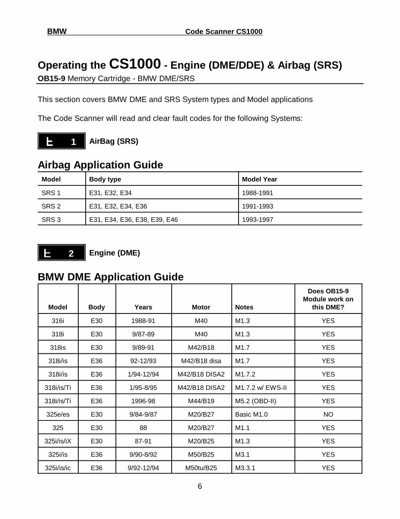
Operating the CS1000 - Engine (DME/DDE) & Airbag (SRS)OB15-9 Memory Cartridge - BMW DME/SRS
This section covers BMW DME and SRS System types and Model applications
The Code Scanner will read and clear fault codes for the following Systems:
���� 1 AirBag (SRS)
Airbag Application GuideModel Body type Model Year
SRS 1 E31, E32, E34 1988-1991
SRS 2 E31, E32, E34, E36 1991-1993
SRS 3 E31, E34, E36, E38, E39, E46 1993-1997
���� 2 Engine (DME)
BMW DME Application Guide
Model Body Years Motor Notes
Does OB15-9Module work on
this DME?
316i E30 1988-91 M40 M1.3 YES
318i E30 9/87-89 M40 M1.3 YES
318is E30 9/89-91 M42/B18 M1.7 YES
318i/is E36 92-12/93 M42/B18 disa M1.7 YES
318i/is E36 1/94-12/94 M42/B18 DISA2 M1.7.2 YES
318i/is/Ti E36 1/95-8/95 M42/B18 DISA2 M1.7.2 w/ EWS-II YES
318i/is/Ti E36 1996-98 M44/B19 M5.2 (OBD-II) YES
325e/es E30 9/84-9/87 M20/B27 Basic M1.0 NO
325 E30 88 M20/B27 M1.1 YES
325i/is/iX E30 87-91 M20/B25 M1.3 YES
325i/is E36 9/90-8/92 M50/B25 M3.1 YES
325i/is/ic E36 9/92-12/94 M50tu/B25 M3.3.1 YES
BMW Code Scanner CS1000
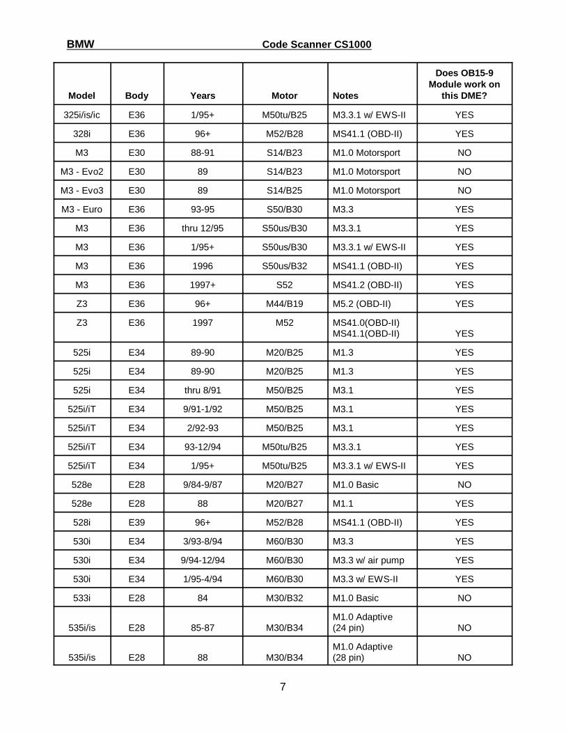
Model Body Years Motor Notes
Does OB15-9Module work on
this DME?
7
325i/is/ic E36 1/95+ M50tu/B25 M3.3.1 w/ EWS-II YES
328i E36 96+ M52/B28 MS41.1 (OBD-II) YES
M3 E30 88-91 S14/B23 M1.0 Motorsport NO
M3 - Evo2 E30 89 S14/B23 M1.0 Motorsport NO
M3 - Evo3 E30 89 S14/B25 M1.0 Motorsport NO
M3 - Euro E36 93-95 S50/B30 M3.3 YES
M3 E36 thru 12/95 S50us/B30 M3.3.1 YES
M3 E36 1/95+ S50us/B30 M3.3.1 w/ EWS-II YES
M3 E36 1996 S50us/B32 MS41.1 (OBD-II) YES
M3 E36 1997+ S52 MS41.2 (OBD-II) YES
Z3 E36 96+ M44/B19 M5.2 (OBD-II) YES
Z3 E36 1997 M52 MS41.0(OBD-II) MS41.1(OBD-II) YES
525i E34 89-90 M20/B25 M1.3 YES
525i E34 89-90 M20/B25 M1.3 YES
525i E34 thru 8/91 M50/B25 M3.1 YES
525i/iT E34 9/91-1/92 M50/B25 M3.1 YES
525i/iT E34 2/92-93 M50/B25 M3.1 YES
525i/iT E34 93-12/94 M50tu/B25 M3.3.1 YES
525i/iT E34 1/95+ M50tu/B25 M3.3.1 w/ EWS-II YES
528e E28 9/84-9/87 M20/B27 M1.0 Basic NO
528e E28 88 M20/B27 M1.1 YES
528i E39 96+ M52/B28 MS41.1 (OBD-II) YES
530i E34 3/93-8/94 M60/B30 M3.3 YES
530i E34 9/94-12/94 M60/B30 M3.3 w/ air pump YES
530i E34 1/95-4/94 M60/B30 M3.3 w/ EWS-II YES
533i E28 84 M30/B32 M1.0 Basic NO
535i/is E28 85-87 M30/B34M1.0 Adaptive (24 pin) NO
535i/is E28 88 M30/B34M1.0 Adaptive (28 pin) NO
BMW Code Scanner CS1000
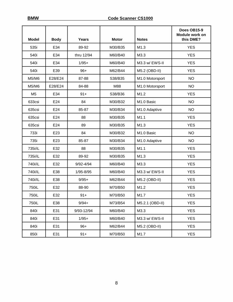
Model Body Years Motor Notes
Does OB15-9Module work on
this DME?
8
535i E34 89-92 M30/B35 M1.3 YES
540i E34 thru 12/94 M60/B40 M3.3 YES
540i E34 1/95+ M60/B40 M3.3 w/ EWS-II YES
540i E39 96+ M62/B44 M5.2 (OBD-II) YES
M5/M6 E28/E24 87-88 S38/B35 M1.0 Motorsport NO
M5/M6 E28/E24 84-88 M88 M1.0 Motorsport NO
M5 E34 91+ S38/B36 M1.2 YES
633csi E24 84 M30/B32 M1.0 Basic NO
635csi E24 85-87 M30/B34 M1.0 Adaptive NO
635csi E24 88 M30/B35 M1.1 YES
635csi E24 89 M30/B35 M1.3 YES
733i E23 84 M30/B32 M1.0 Basic NO
735i E23 85-87 M30/B34 M1.0 Adaptive NO
735i/iL E32 88 M30/B35 M1.1 YES
735i/iL E32 89-92 M30/B35 M1.3 YES
740i/iL E32 9/92-4/94 M60/B40 M3.3 YES
740i/iL E38 1/95-8/95 M60/B40 M3.3 w/ EWS-II YES
740i/IL E38 9/95+ M62/B44 M5.2 (OBD-II) YES
750iL E32 88-90 M70/B50 M1.2 YES
750iL E32 91+ M70/B50 M1.7 YES
750iL E38 9/94+ M73/B54 M5.2.1 (OBD-II) YES
840i E31 9/93-12/94 M60/B40 M3.3 YES
840i E31 1/95+ M60/B40 M3.3 w/ EWS-II YES
840i E31 96+ M62/B44 M5.2 (OBD-II) YES
850i E31 91+ M70/B50 M1.7 YES
BMW Code Scanner CS1000
9
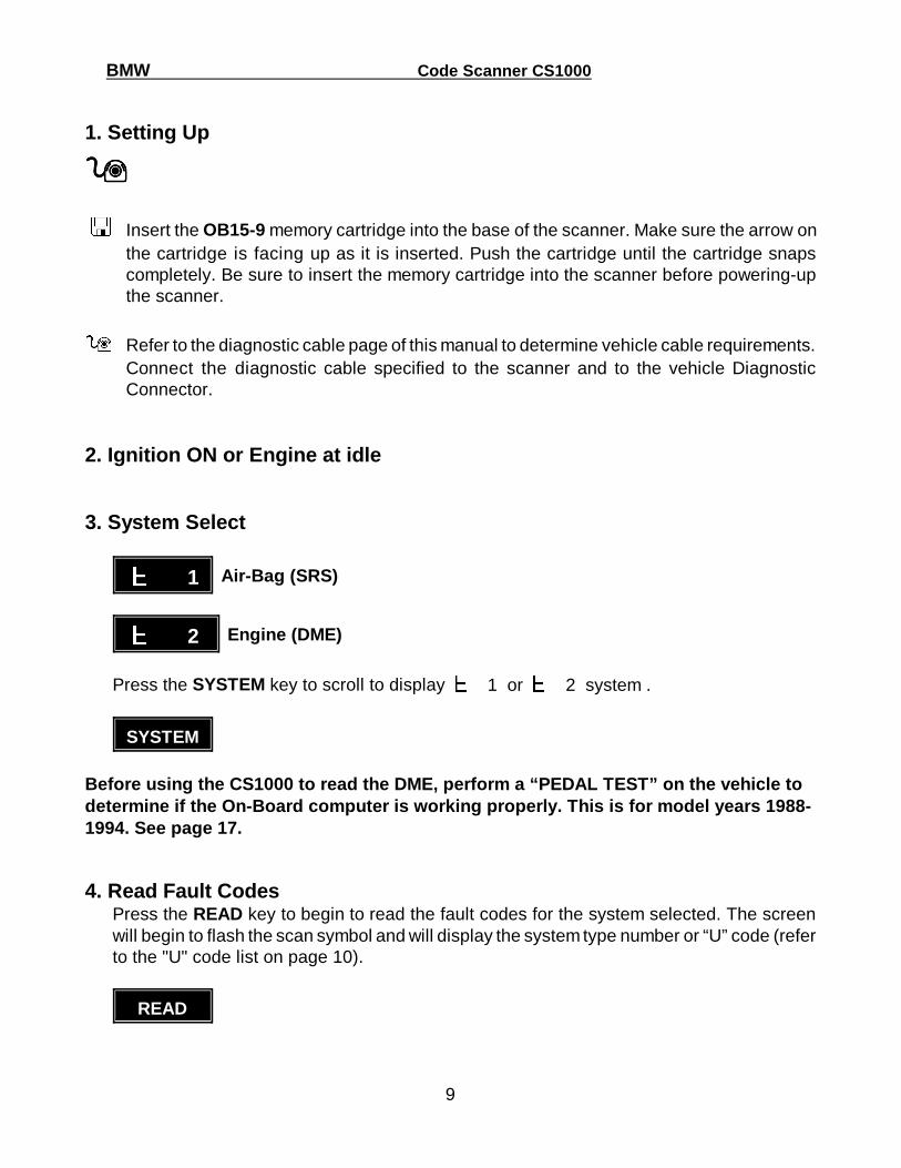
1. Setting Up
����
� Insert the OB15-9 memory cartridge into the base of the scanner. Make sure the arrow onthe cartridge is facing up as it is inserted. Push the cartridge until the cartridge snapscompletely. Be sure to insert the memory cartridge into the scanner before powering-upthe scanner.
� Refer to the diagnostic cable page of this manual to determine vehicle cable requirements.Connect the diagnostic cable specified to the scanner and to the vehicle DiagnosticConnector.
2. Ignition ON or Engine at idle
3. System Select
���� 1 Air-Bag (SRS)
���� 2 Engine (DME)
Press the SYSTEM key to scroll to display � 1 or � 2 system .
SYSTEM
Before using the CS1000 to read the DME, perform a “PEDAL TEST” on the vehicle todetermine if the On-Board computer is working properly. This is for model years 1988-1994. See page 17.
4. Read Fault CodesPress the READ key to begin to read the fault codes for the system selected. The screenwill begin to flash the scan symbol and will display the system type number or “U” code (referto the "U" code list on page 10).
READ
BMW Code Scanner CS1000
10
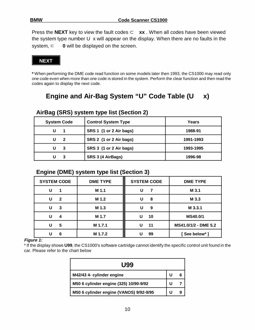
Press the NEXT key to view the fault codes ���� xx . When all codes have been viewedthe system type number U x will appear on the display. When there are no faults in thesystem, ���� 0 will be displayed on the screen.
NEXT
* When performing the DME code read function on some models later then 1993, the CS1000 may read onlyone code even when more than one code is stored in the system. Perform the clear function and then read thecodes again to display the next code.
Engine and Air-Bag System “U” Code Table (U x)
AirBag (SRS) system type list (Section 2)
System Code Control System Type Years
U 1 SRS 1 (1 or 2 Air bags) 1988-91
U 2 SRS 2 (1 or 2 Air bags) 1991-1993
U 3 SRS 3 (1 or 2 Air bags) 1993-1995
U 3 SRS 3 (4 AirBags) 1996-98
Engine (DME) system type list (Section 3)
SYSTEM CODE DME TYPE SYSTEM CODE DME TYPE
U 1 M 1.1 U 7 M 3.1
U 2 M 1.2 U 8 M 3.3
U 3 M 1.3 U 9 M 3.3.1
U 4 M 1.7 U 10 MS40.0/1
U 5 M 1.7.1 U 11 MS41.0/1/2 - DME 5.2
U 6 M 1.7.2 U 99 [ See below* ]Figure 1:* If the display shows U99, the CS1000's software cartridge cannot identify the specific control unit found in thecar. Please refer to the chart below
U99M42/43 4- cylinder engine U 6
M50 6 cylinder engine ( 325) 10/90-9/92 U 7
M50 6 cylinder engine (VANOS) 9/92-9/95 U 9
BMW Code Scanner CS1000
11
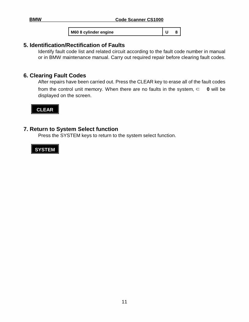
M60 8 cylinder engine U 8
5. Identification/Rectification of FaultsIdentify fault code list and related circuit according to the fault code number in manualor in BMW maintenance manual. Carry out required repair before clearing fault codes.
6. Clearing Fault CodesAfter repairs have been carried out. Press the CLEAR key to erase all of the fault codes
from the control unit memory. When there are no faults in the system, ���� 0 will bedisplayed on the screen.
CLEAR
7. Return to System Select functionPress the SYSTEM keys to return to the system select function.
SYSTEM

BMW Code Scanner CS1000
12
Operating the CS1000 - Transmission (EGS)OB15-3 Memory Cartridge - BMW Transmission (EGS)
Transmission (EGS) System Code “U” List (Code Section 4)System Number Control system type Years
U 1 EGS 1.2x 1988-1992
U 4 EGS 4.xx 1992-1995
U 7 EGS 7.xx 1993-1995
U 8 EGS 1.2x 1988-1992
U 9 EGS 9.xx 1993-1995
1. Setting Up:
���� � Insert the OB15-3 memory cartridge into the base of the scanner. Make sure the arrow on
the cartridge is facing up as it is inserted. Push the cartridge until the cartridge snapscompletely. Be sure to insert the memory cartridge into the scanner before powering-upthe scanner.
� Refer to the diagnostic cable page of this manual to determine vehicle cable requirements.Connect the diagnostic cable specified to the scanner and to the vehicle DiagnosticConnector.
2. Ignition ON or Engine at idle
3. Read Fault CodesPress the READ key to begin to read the fault codes for the system selected. The screen willbegin to flash the scan symbol and will display the system type number (refer to the "U" codelist on page 13).
READ
Press the NEXT key to scroll to view the fault codes ���� xx and system type number U

BMW Code Scanner CS1000
13
x. When there are no faults in the system, ���� 0 will be displayed on the screen.
NEXT
* When performing the DME code read function on some models later then 1993, theCS1000 may read only one code even when more than one code is stored in the system.Perform the clear function and then read the codes again to display the next code.
4. Identification/Rectification of FaultsIdentify fault code list and related circuit according to the fault code number in manual or inBMW maintenance manual. Carry out required repair before clearing fault codes.
5. Clear Fault CodeAfter repairs have been carried out. Press the CLEAR key to erase all of the fault codes from
the control unit memory. When there are no faults in the system, ���� 0 will be displayed onthe screen.
CLEAR

BMW Code Scanner CS1000
14
Operating the CS1000 - Service Interval Reset OB15-5 Memory Cartridge - SERVICE RESET
1. Setting Up
����
� Insert the OB15-3 memory cartridge into the base of the scanner. Make sure the arrow onthe cartridge is facing up as it is inserted. Push the cartridge until the cartridge snapscompletely. Be sure to insert the memory cartridge into the scanner before powering-upthe scanner.
� Refer to the diagnostic cable page of this manual to determine vehicle cable requirements.Connect the diagnostic cable specified to the scanner and to the vehicle DiagnosticConnector.
2. Ignition ON
Note: The Scanner will automatically perform an OIL Service Interval reset when poweris supplied.
3. System Select
���� 1 OIL Reset
���� 2 INSPECTION Reset
Press the SYSTEM key to scroll the display to the ���� 1 or ���� 2 system .
SYSTEM

BMW Code Scanner CS1000
15
4. Reset Service CounterPress the CLEAR key to reset the service interval counter.
CLEAR
5. Return to System Select functionPress the SYSTEM keys to select the next function.
SYSTEM

BMW Code Scanner CS1000
16
SECTION 2 DME/DDE Fault Code Lists
BMW MOTRONIC PEDAL TEST FAULT CODES
All 1989-94 BMW vehicles are equipped with a self diagnostic system for the detection of injection faults. Whena fault is detected by the system the Electronic Control Unit (ECU) records the code corresponding to the defectin the ECU's memory until either:
1) The vehicle battery or the ECU is disconnected.2) The engine is started 60 times with no recurrence of the fault.3) The ECU memory is cleared using the BMW MODIC, DIS, Bosch KTS300, KTS500, or the Baum Tools
CS1000 or CS2000 BMW hand held scanner.
To review the FAULT CODES from the ECU memory use the following procedure:
1) Turn the ignition switch to the 'engine run' position.2) Depress the gas pedal to the floor 5 times.
The CHECK ENGINE light will blink out the FAULT CODES starting with the lowest number first. These FAULTCODES consist of 4 digits each separated by a short pause (ie. blink pause blink blink pause blink pause blinktranslates as 1 2 1 1).
BMW ‘PEDAL’ FAULT CODES (Models 1989-94)
CODE MALFUNCTIONING SYSTEM
1211 DME Control Unit
1212 EGO(O2) Sensor 2
1213 Lambda Control 2
1215 Air Mass/Volume Sensor
1216 Throttle Potentiometer
1218 Output Stage, Group 1
1219 Output Stage, Group 2
1221 EGO(O2) Sensor 1
1222 Lambda Control 1
1223 Coolant Temp. Sensor
1224 Intake Air Temp. Sensor
1225 Knock Sensor 1
1226 Knock Sensor 2
1227 Knock Sensor 3
1228 Knock Sensor 4
1231 Battery Voltage/DME Main Relay
1232 Throttle Switch - Idle
1233 Throttle Switch - WOT
1234 Speedometer A Signal
1237 A/C Compressor cut off
1241 False Air Mass Sensor Code - Update EPROMand replace Idle Valve
1242 A/C Compressor
1243 Crankshaft Pulse Sensor
1244 Camshaft Sensor
1245 Intervention EGS
1247 Ignition Secondary Monitor
1251 Fuel Injector 1 (or group 1)
1252 Fuel Injector 2 (or group 2)
1253 Fuel Injector 3
1254 Fuel Injector 4

BMW Code Scanner CS1000
Copyright © October 24, 1997 Baum Tools Unlimited Inc. All rights reserved.Reproduction in whole or in part in any form or medium without express written permission of Baum Tools Unlimited Inc. is prohibited.
17
1255 Fuel Injector 5
1256 Fuel Injector 6
1257 Fuel Injector 7
1258 Fuel Injector 8
1261 Fuel Pump Relay Control
1262 Idle Speed Actuator
1263 Purge Valve
1264 EGO(O2) Heater
1265 Fault Lamp (check engine)
1266 VANOS
1267 Air Pump Relay Control
1271 Ignition Coil 1
1272 Ignition Coil 2
1273 Ignition Coil 3
1274 Ignition Coil 4
1275 Ignition Coil 5
1276 Ignition Coil 6
1277 Ignition Coil 7
1278 Ignition Coil 8
1281 Control Unit Memory Supply
1282 Fault Code Memory
1283 Fuel Injector Output Stage
1286 Knock Control test Pulse
1444 No Failures
*In the 12 cylinder model the Injection system is treatedas two 6 cylinder systems joined at the crank. Thismeans there are two ECUs in the system. To accessthe second ECU depress the gas pedal to the floor 6times.
Some models will return implausible blink codes if the ECU has failed or if the power is interrupted duringoperation. Remove the control units harness and reconnect after 10 minutes to reset the base values. This seemsto resolve most of these problems.

BMW DME/DDE DIAGNOSTIC FAULT CODES
Copyright © October 24, 1997 Baum Tools Unlimited Inc. All rights reserved.Reproduction in whole or in part in any form or medium without express written permission of Baum Tools Unlimited Inc. is prohibited.
18
��� ��� ����� ��� ����� ��� ����� ��� �� - DME 1.1, 1.2, 1.3 / 4, 6 & 12-Cylinder
M20, M30, M70 (1988-90), S38
Fault Malfunction
1 Fault in the DME control Unit
3 Fuel Pump Relay (EKP) or no TR Signal
4 Idle-speed Controller - Opening Winding
5 Tank Ventilation Valve
7 Air-flow Sensor
10 Oxygen Sensor (Lambda) Control Feedback (Air or FuelLeak Likely)
15 Check Engine Light Failure (Check both bulbs)
16 Injection Valve(s), Cylinder 1+3, 1+3+5 or 7+9+11
17 Injection Valve(s), Cylinder 2+4, 2+4+6 or 8+10+12
22 Idle Speed Controller - Closing Windiing
23 Oxygen (Lambda) Sensor - Heater/Air Pump Relay
28 Oxygen (Lambda) Sensor
29 Vehicle Speed Signal
33 Kick Down Prevention Solenoid in Transmission (short)
37 Control Unit Power Supply B+
38 ASC/DWA short on pin 38 of DME, ground or B+
40 Air Conditioner Compressor
43 Idle-speed Co-potentiometer
44 Temperature-sensor - Air Intake
45 Temperature-sensor - Coolant
50 Intervention, Engine Drag Torque Control (MSR)
51 Ignition Timing (Angle) Intervention
52 Idle-speed Switch
53 Wide-open-throttle Switch
54 Torque Converter Lockup Clutch
100 DME Control Unit Final Stage
��� ����� ����� ����� �� - DME 1.7, 1.7.1 / 4 & 12-Cylinder
M40, M42, S70 Engine
Fault Malfunction
0 Undefined Fault
1 Fuel Pump Relay (EKP) / RPM Signal
2 Idle Actuator - Closing Winding
3 Fuel Injector on 4 cyl. 1 + 3, 12 cyl. 2+4+6 or 8+10+12
6 Fuel Injector output stage without cylinder assignment
8 Fault Lamp (US Model only)
12 Throttle Valve Potentiometer
16 Ignition Reference Signal, 6 cyl. Cam, 12 cyl #6 or #12
18 Control Unit Output Stage (short), Pin 18
19 Control Unit Output Stage (short), Pin 19
29 Idle Actuator
32 Fuel Injector, Cylinder 1+3+5 or 7+9+11
36 Tank Ventilation Valve
37 Oxygen Sensor Heater Relay
41 Air Flow Sensor
48 Air Conditioner Compressor Cutoff
54 Control Unit Power Supply B+
63 Torque Converter Lockup Clutch
64 Ignition Timing Intervention (signal from EGS)
70 Oxygen Sensor
73 Vehicle Speed Sensor Signal
76 Idle CO Potentiometer
77 Temperature Sensor - Air Intake
78 Temperature Sensor - Engine Coolant
82 Intervention, Engine Drag Torque Control (MSR)
83 Intervention, Automatic Stability Control (ASC)
85 Air Condition Compressor (Belt Slip or Seizing)
100 Control Unit, Output Stage
200 Control Unit (RAM, ROM/EPROM)
201 Oxygen Sensor (Lambda) Control Feedback (Air or FuelLeak Likely)
255 Control Unit Internal Fault
���� - DME1.7.2 / 4 Cylinder
M42, M43 Engine
Fault Malfunction
0 Undefined fault
1 Fuel pump relay (EKP)
2 Idle Speed Controller
3 Fuel Injector #1 & #3 cylinder
8 Fault Lamp (US model only)
12 Throttle Valve Potentiometer

BMW DME/DDE DIAGNOSTIC FAULT CODES
Copyright © October 24, 1997 Baum Tools Unlimited Inc. All rights reserved.Reproduction in whole or in part in any form or medium without express written permission of Baum Tools Unlimited Inc. is prohibited.
19
15 Knock Sensor 1
16 Camshaft Sensor
18 Changeover Valve, DISA Butterfly
29 Idle Actuator
32 Fuel Injector, #2 & #4 cylinder
36 Tank Ventilation Valve
37 Oxygen-Sensor Heater
41 Air Flow Sensor
42 Knock Sensor 2
48 Air-Conditioner Compressor Cutoff
54 Control-Unit Power Supply B+
55 Ignition, #1 & #4 cylinder
64 Ignition Timing Intervention (signal from EGS)
70 Oxygen Sensor
73 Vehicle Speed Sensor Signal
76 Idle CO Potentiometer
77 Temperature Sensor - Air Intake
78 Temperature Sensor - Engine Coolant
85 Air Condition Compressor
100 This code pinpointed elsewhere
153 Control Voltage of Knock Control
201 Oxygen Sensor Control
255 Control Unit Internal Fault
���� - DME 3.1 / 6-Cylinder
M40, M42, M50 (1991-93), S70 Engine
Fault Malfunction
0 Undefined Fault
1 Fuel Pump Relay (EKP)
2 Idle Actuator - Closing Winding
3 Fuel Injector on Cylinder #1
4 Fuel Injector on Cylinder #3
5 Fuel Injector on Cylinder #2
6 Fuel Injector output stage without cylinder assignment
8 Fault Lamp (US Model only)
12 Throttle Valve Potentiometer
16 Ignition Reference Signal, Cam
18 Control Unit, Output Stage (short) Pin 18
19 Control Unit, Output Stage (short) Pin 19
23 Ignition Cylinder #2
24 Ignition Cylinder #3
25 Ignition Cylinder #1
26 Control Unit Supply Voltage B+ (Too High or Low)
29 Idle Actuator- Opening Winding
31 Fuel Injector, Cylinder #5
32 Fuel Injector, Cylinder #6
33 Fuel Injector, Cylinder #4
36 Tank Ventilation Valve
37 Oxygen Sensor Heater
41 Air Flow Sensor
46 Control Unit, Output Stage
48 Air Conditioner Compressor Cutoff
50 Ignition, Cylinder #4
51 Ignition, Cylinder #6
52 Ignition, Cylinder #5
54 DME Control Unit Power Supply via Main Relay
55 Ignition Final Stage
62 Electronic Throttle Control Signal (EML)
64 Ignition Timing Intervention (signal from EGS)
67 Crankshaft Pulse Generator
70 Oxygen Sensor (Short or Break)
73 Vehicle Speed Sensor Signal
77 Temperature Sensor - Air Intake
78 Temperature Sensor - Engine Coolant
81 Antitheft System Signal (DWA)
82 Intervention, Engine Drag Torque Control (MSR)
83 Intervention, Automatic Stability Control (ASC)
85 Air Condition Compressor (Belt Slip or Seizing)
100 Control Unit, Output Stage Ignition
200 Control Unit (RAM, ROM/EPROM)
201 Oxygen Sensor (Lambda) Control Feedback (Air or FuelLeak Likely)
202 Fault Memory in Control Unit Fault
203 Ignition Circuit Monitor - No Primary Ignition Signal
204 Idle Speed Increase During MSR Operation (StallProtect)
255 Control Unit Internal Fault
BMW DME/DDE DIAGNOSTIC FAULT CODES
Copyright © October 24, 1997 Baum Tools Unlimited Inc. All rights reserved.Reproduction in whole or in part in any form or medium without express written permission of Baum Tools Unlimited Inc. is prohibited.
20
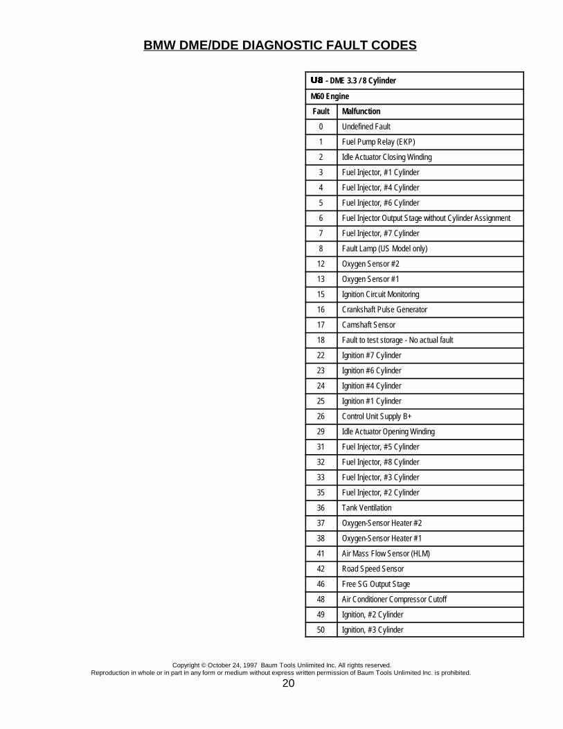
�������� - DME 3.3 / 8 Cylinder
M60 Engine
Fault Malfunction
0 Undefined Fault
1 Fuel Pump Relay (EKP)
2 Idle Actuator Closing Winding
3 Fuel Injector, #1 Cylinder
4 Fuel Injector, #4 Cylinder
5 Fuel Injector, #6 Cylinder
6 Fuel Injector Output Stage without Cylinder Assignment
7 Fuel Injector, #7 Cylinder
8 Fault Lamp (US Model only)
12 Oxygen Sensor #2
13 Oxygen Sensor #1
15 Ignition Circuit Monitoring
16 Crankshaft Pulse Generator
17 Camshaft Sensor
18 Fault to test storage - No actual fault
22 Ignition #7 Cylinder
23 Ignition #6 Cylinder
24 Ignition #4 Cylinder
25 Ignition #1 Cylinder
26 Control Unit Supply B+
29 Idle Actuator Opening Winding
31 Fuel Injector, #5 Cylinder
32 Fuel Injector, #8 Cylinder
33 Fuel Injector, #3 Cylinder
35 Fuel Injector, #2 Cylinder
36 Tank Ventilation
37 Oxygen-Sensor Heater #2
38 Oxygen-Sensor Heater #1
41 Air Mass Flow Sensor (HLM)
42 Road Speed Sensor
46 Free SG Output Stage
48 Air Conditioner Compressor Cutoff
49 Ignition, #2 Cylinder
50 Ignition, #3 Cylinder
BMW DME/DDE DIAGNOSTIC FAULT CODES
Copyright © October 24, 1997 Baum Tools Unlimited Inc. All rights reserved.Reproduction in whole or in part in any form or medium without express written permission of Baum Tools Unlimited Inc. is prohibited.
21
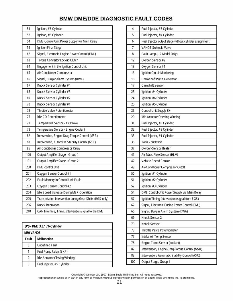
51 Ignition, #8 Cylinder
52 Ignition, #5 Cylinder
54 DME Control Unit Power Supply via Main Relay
55 Ignition Final Stage
62 Signal, Electronic Engine Power Control (EML)
63 Torque Convertor Lockup Clutch
64 Engagement in the Ignition Control Unit
65 Air Conditioner Compressor
66 Signal, Burglar Alarm System (DWA)
67 Knock Sensor Cylinder #4
68 Knock Sensor Cylinder #3
69 Knock Sensor Cylinder #2
70 Knock Sensor Cylinder #1
73 Throttle Valve Potentiometer
76 Idle CO Potentiometer
77 Temperature Sensor - Air Intake
78 Temperature Sensor - Engine Coolant
82 Intervention, Engine Drag Torque Control (MSR)
83 Intervention, Automatic Stability Control (ASC)
85 Air Conditioner Compressor Relay
100 Output Amplifier Stage - Group 1
101 Output Amplifier Stage - Group 2
200 DME control Unit
201 Oxygen Sensor Control #1
202 Fault Memory in Control Unit Fault
203 Oxygen Sensor Control #2
204 Idle Speed Increase During MSR Operation
205 Transmission Intervention during Gear-Shifts (EGS only)
206 Knock Regulation
210 CAN Interface, Trans. Intervention signal to the DME
�������� - DME 3.3.1 / 6-Cylinder
M50 VANOS
Fault Malfunction
0 Undefined Fault
1 Fuel Pump Relay (EKP)
2 Idle-Actuator Closing Winding
3 Fuel Injector, #5 Cylinder
4 Fuel Injector, #6 Cylinder
5 Fuel Injector, #4 Cylinder
6 Fuel Injector output stage without cylinder assignment
7 VANOS Solenoid Valve
8 Fault Lamp (US Model Only)
12 Oxygen Sensor #2
13 Oxygen Sensor #1
15 Ignition-Circuit Monitoring
16 Crankshaft Pulse Generator
17 Camshaft Sensor
23 Ignition, #4 Cylinder
24 Ignition, #6 Cylinder
25 Ignition, #5 Cylinder
26 Control-Unit Supply B+
29 Idle-Actuator Opening Winding
31 Fuel Injector, #3 Cylinder
32 Fuel Injector, #2 Cylinder
33 Fuel Injector, #1 Cylinder
36 Tank Ventilation
37 Oxygen-Sensor Heater
41 Air-Mass Flow Sensor (HLM)
42 Vehicle Speed Sensor
48 Air-Conditioner Compressor Cutoff
50 Ignition, #1 Cylinder
51 Ignition, #2 Cylinder
52 Ignition, #3 Cylinder
54 DME Control-Unit Power Supply via Main Relay
57 Ignition Timing Intervention (signal from EGS)
62 Signal, Electronic Engine Power Control (EML)
66 Signal, Burglar Alarm System (DWA)
69 Knock Sensor 2
70 Knock Sensor 1
73 Throttle Valve Potentiometer
77 Intake Air Temp Sensor
78 Engine Temp Sensor (coolant)
82 Intervention, Engine-Drag-Torque Control (MSR)
83 Intervention, Automatic Stability Control (ASC)
100 Output Stage, Group 1

BMW DME/DDE DIAGNOSTIC FAULT CODES
Copyright © October 24, 1997 Baum Tools Unlimited Inc. All rights reserved.Reproduction in whole or in part in any form or medium without express written permission of Baum Tools Unlimited Inc. is prohibited.
22
101 Output Stage, Group 2
200 DME Control Unit (RAM, ROM/EPROM)
201 Oxygen Sensor Control
202 Fault Memory in Control Unit
204 Idle Speed Increase during MSR Operation
206 Knock Control Test Pulse
�� �� �� �� - DME MS40.0 / MS40.1
Fault Malfunction
1 Ignition Fault : Cylinder 1
2 Ignition Fault : Cylinder 3
3 Ignition Fault : Cylinder 5
5 Fuel Injector Fault : Cylinder 6
6 Fuel Injector Fault : Cylinder 4
10 Air-Conditioner Compressor
12 Vehicle Speed Signal
14 Transmission Intervention
22 Fuel Injector Fault : Cylinder 3
23 Fuel Injector Fault : Cylinder 1
24 Air Conditioner Compressor Control
27 Idle Actuator
29 Ignition Fault : Cylinder 2
30 Ignition Fault : Cylinder 4
31 Ignition Fault : Cylinder 6
33 Fuel Injector Fault : Cylinder 5
49 Power Supply to DME Control Unit
50 Fuel Injector Fault : Cylinder 2
51 Evaporation Control Valve
52 Fuel Pump Relay (EKP)
53 Oxygen Sensor Heater
62 Ignition Signal Feedback
63 Knock Sensor Fault : Cylinder 4+5+6
64 Knock Sensor Fault : Cylinder 1+2+3
68 Hot Film Air Mass Meter
75 Oxygen Sensor Voltage
77 Throttle Potentiometer
79 Crankshaft Angle Pulse Generator
81 Engine Coolant Temperature Sensor
84 Camshaft Angle Pulse Generator
85 Intake Air Temperature Sensor
97 Fuel Evaporation Control Valve Jammed
98 Idle Actuator Jammed
99 Lambda Regulation Limit Exceeded
100 DME Control Unit Fault
������������ - MS41.0 / MS41.1
M52, S50us/B32
Fault Malfunction
1 Ignition Coil : Cylinder 2
2 Ignition Coil : Cylinder 4
3 Ignition Coil : Cylinder 6
5 Fuel Injector : Cylinder 2
6 Fuel Injector : Cylinder 1
8 Mass or Volume Air Flow Circuit, Range/Perf.
10 Engine Coolant Temperature Sensor Circuit
11 Fuel Tank Pressure Sensor - EVAP
12 Throttle Position Sensor
14 Intake Air Temperature Sensor
16 AC Compressor Pulse Width Signal (E-39 only)
18 EWS Signal not present or faulty
20 Malfunction Indicator Lamp (MIL) - USA Only
21 VANOS: electrical fault
22 Fuel Injector : Cylinder 3
23 Fuel Injector : Cylinder 6
24 Fuel Injector : Cylinder 4
25 Oxygen Sensor Heater : Bank 1 (Pre Cat. Conv.)
27 Idle Actuator : Closing Coil
29 Ignition Coil : Cylinder 1
30 Ignition Coil : Cylinder 3
31 Ignition Coil : Cylinder 5
33 Fuel Injector : Cylinder 5
35 Relay or Pump - Secondary air injection system
47 Temperature Sensor : Downstream of Pre-catalyticconverter
50 Evaporation Control Valve - EVAP
51 Shut-off Valve : EVAP Activated Charcoal Filter
BMW DME/DDE DIAGNOSTIC FAULT CODES
Copyright © October 24, 1997 Baum Tools Unlimited Inc. All rights reserved.Reproduction in whole or in part in any form or medium without express written permission of Baum Tools Unlimited Inc. is prohibited.
23
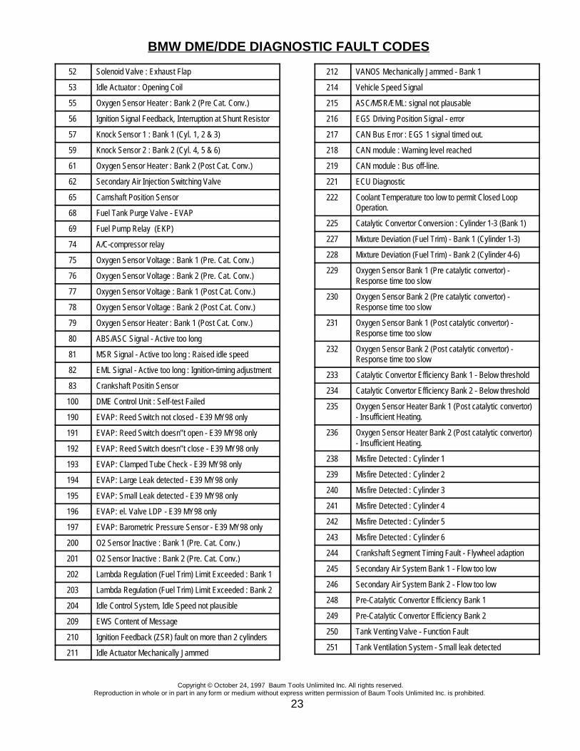
52 Solenoid Valve : Exhaust Flap
53 Idle Actuator : Opening Coil
55 Oxygen Sensor Heater : Bank 2 (Pre Cat. Conv.)
56 Ignition Signal Feedback, Interruption at Shunt Resistor
57 Knock Sensor 1 : Bank 1 (Cyl. 1, 2 & 3)
59 Knock Sensor 2 : Bank 2 (Cyl. 4, 5 & 6)
61 Oxygen Sensor Heater : Bank 2 (Post Cat. Conv.)
62 Secondary Air Injection Switching Valve
65 Camshaft Position Sensor
68 Fuel Tank Purge Valve - EVAP
69 Fuel Pump Relay (EKP)
74 A/C-compressor relay
75 Oxygen Sensor Voltage : Bank 1 (Pre. Cat. Conv.)
76 Oxygen Sensor Voltage : Bank 2 (Pre. Cat. Conv.)
77 Oxygen Sensor Voltage : Bank 1 (Post Cat. Conv.)
78 Oxygen Sensor Voltage : Bank 2 (Post Cat. Conv.)
79 Oxygen Sensor Heater : Bank 1 (Post Cat. Conv.)
80 ABS/ASC Signal - Active too long
81 MSR Signal - Active too long : Raised idle speed
82 EML Signal - Active too long : Ignition-timing adjustment
83 Crankshaft Positin Sensor
100 DME Control Unit : Self-test Failed
190 EVAP: Reed Switch not closed - E39 MY98 only
191 EVAP: Reed Switch doesn’’t open - E39 MY98 only
192 EVAP: Reed Switch doesn’’t close - E39 MY98 only
193 EVAP: Clamped Tube Check - E39 MY98 only
194 EVAP: Large Leak detected - E39 MY98 only
195 EVAP: Small Leak detected - E39 MY98 only
196 EVAP: el. Valve LDP - E39 MY98 only
197 EVAP: Barometric Pressure Sensor - E39 MY98 only
200 O2 Sensor Inactive : Bank 1 (Pre. Cat. Conv.)
201 O2 Sensor Inactive : Bank 2 (Pre. Cat. Conv.)
202 Lambda Regulation (Fuel Trim) Limit Exceeded : Bank 1
203 Lambda Regulation (Fuel Trim) Limit Exceeded : Bank 2
204 Idle Control System, Idle Speed not plausible
209 EWS Content of Message
210 Ignition Feedback (ZSR) fault on more than 2 cylinders
211 Idle Actuator Mechanically Jammed
212 VANOS Mechanically Jammed - Bank 1
214 Vehicle Speed Signal
215 ASC/MSR/EML: signal not plausable
216 EGS Driving Position Signal - error
217 CAN Bus Error : EGS 1 signal timed out.
218 CAN module : Warning level reached
219 CAN module : Bus off-line.
221 ECU Diagnostic
222 Coolant Temperature too low to permit Closed LoopOperation.
225 Catalytic Convertor Conversion : Cylinder 1-3 (Bank 1)
227 Mixture Deviation (Fuel Trim) - Bank 1 (Cylinder 1-3)
228 Mixture Deviation (Fuel Trim) - Bank 2 (Cylinder 4-6)
229 Oxygen Sensor Bank 1 (Pre catalytic convertor) -Response time too slow
230 Oxygen Sensor Bank 2 (Pre catalytic convertor) -Response time too slow
231 Oxygen Sensor Bank 1 (Post catalytic convertor) -Response time too slow
232 Oxygen Sensor Bank 2 (Post catalytic convertor) -Response time too slow
233 Catalytic Convertor Efficiency Bank 1 - Below threshold
234 Catalytic Convertor Efficiency Bank 2 - Below threshold
235 Oxygen Sensor Heater Bank 1 (Post catalytic convertor)- Insufficient Heating.
236 Oxygen Sensor Heater Bank 2 (Post catalytic convertor)- Insufficient Heating.
238 Misfire Detected : Cylinder 1
239 Misfire Detected : Cylinder 2
240 Misfire Detected : Cylinder 3
241 Misfire Detected : Cylinder 4
242 Misfire Detected : Cylinder 5
243 Misfire Detected : Cylinder 6
244 Crankshaft Segment Timing Fault - Flywheel adaption
245 Secondary Air System Bank 1 - Flow too low
246 Secondary Air System Bank 2 - Flow too low
248 Pre-Catalytic Convertor Efficiency Bank 1
249 Pre-Catalytic Convertor Efficiency Bank 2
250 Tank Venting Valve - Function Fault
251 Tank Ventilation System - Small leak detected

BMW DME/DDE DIAGNOSTIC FAULT CODES
Copyright © October 24, 1997 Baum Tools Unlimited Inc. All rights reserved.Reproduction in whole or in part in any form or medium without express written permission of Baum Tools Unlimited Inc. is prohibited.
24
252 Tank Ventilation System - Suction Fault, Incorrect purgeflow
253 Shut-off Valve - Jammed shut
254 Tank Ventilation System - Large Volume Air Leak (Gascap off)
255 Tank Venting Valve - Jammed Open
333 DME Control Unit : Self-test Failed
������������ - DME 5.2
M44, M62, M73
Fault Description
1 EVAP: LDP Valve - Final Stage - M62/M73 MY98 only
2 Running losses valve - final stage - M62/M73 MY98 only
3 EVAP: Reed Switch not closed, doesn’’t open or doesn’’tclose - M62/M73 MY98 only
4 O2-Sensor-Heater, Post Cat.(Bank2), InsufficientHeating.
5 O2 Sensor Heater, Pre Cat.(Bank2), insufficient.
6 CAN-Timeout Instrument Cluster - M62/M73 MY98 only
7 Engine coolant temperature, radiator outlet - M62/M73MY98 only
8 Misfire with low fuel detected
10 O2 Sensor Pre Cat. (Bank1)
12 O2 Sensor Post Cat.(Bank1)
13 O2 Sensor Heater Circuit Pre Cat (Bank1)
14 O2-Sensor-Heater, Post Cat. (Bank1), insufficient.
15 O2 Sensor Pre Cat. (Bank1), Slow Response time
16 O2-Sensor Pre Cat (Bank 1)
17 O2 Sensor Post Cat. (Bank1), Slow Response time
18 O2 Sensor Pre Cat. (Bank2)
19 CAN Signal, Timeout EKAT - M73LEV MY99 only
20 O2 Sensor Post Cat. (Bank2)
21 O2 Sensor Pre Cat. (Bank2) Slow Response time
22 O2-Sensor Pre Cat (Bank 2)
23 O2 Sensor Post Cat. (Bank2) Slow Response time
24 AC Compressor Function
26 Fuel Trim (Bank1), Multiplicative
27 Fuel Adaptation Additive with airleak (Bank 1)
28 Fuel Trim (Bank1), Additive
29 air containment valve for air control of shrouded fuelinjector (Bank 1) - M62/M73 MY98 only
30 EKAT-Status 7 - power switch control - M73LEV MY99only
32 Idle Control Valve stuck mechanically
33 EKAT-Status 8 - EKAT-ECU - M73LEV MY99 only
34 Fuel Trim (Bank2), Multiplicative
35 Fuel Adaptation Additive with airleak (Bank 2)
36 Fuel Trim (Bank2), Additive
39 EWS Content of Message
40 Catalyst Efficiency Bank 1, Below Threshold
42 Vehicle Speed Sensor 1995-97
42 EKAT-Status 1 - Disconnection of heater for Catalyst 1 -M73LEV MY99 only
43 EKAT-Status 2 - switch on operating condition catalyst 1 -M73LEV MY99 only
44 EKAT-Status 3 - power switch Catalyst 1 - M73LEVMY99 only
45 Catalyst Efficiency Bank 2, Below Threshold
46 EKAT-Status 4 - Disconnection heater for Catalyst 2 -M73LEV MY99 only
47 EKAT-Status 5 - switch on operating condition catalyst 2 -M73LEV MY99 only
48 EKAT-Status 6 - power switch catalyst 2 - M73LEV MY99only
50 Cylinder 1 Misfire detected
51 Cylinder 2 Misfire detected
52 Cylinder 3 Misfire detected
53 Cylinder 4 Misfire detected
54 Cylinder 5 Misfire detected
55 Cylinder 6 Misfire detected
56 Cylinder 7 Misfire detected
57 Cylinder 8 Misfire detected
62 Random/Multiple Cylinder, Misfire detected
63 Cylinder 1 Misfire detected, catalyst damaging
64 Cylinder 2 Misfire detected, catalyst damaging
65 Cylinder 3 Misfire detected, catalyst damaging
66 Cylinder 4 Misfire detected, catalyst damaging
67 Cylinder 5 Misfire detected, catalyst damaging
68 Cylinder 6 Misfire detected, catalyst damaging
69 Cylinder 7 Misfire detected, catalyst damaging

BMW DME/DDE DIAGNOSTIC FAULT CODES
Copyright © October 24, 1997 Baum Tools Unlimited Inc. All rights reserved.Reproduction in whole or in part in any form or medium without express written permission of Baum Tools Unlimited Inc. is prohibited.
25
70 Cylinder 8 Misfire detected, catalyst damaging
71 Cylinder 9 Misfire detected, catalyst damaging
72 Cylinder 10 Misfire detected, catalyst damaging
73 Cylinder 11 Misfire detected, catalyst damaging
74 Cylinder 12 Misfire detected, catalyst damaging
75 Random/Multiple Cylinder, Misfire detected
77 air containment valve for air control of shrouded fuelinjector (Bank 2) - M62/M73 MY98 only
78 Crankshaft Position Sensor (too many teeth)
80 Secondary Air Control
81 EKAT-Status 9 - sensor check temperature sensor (1) inbattery - M73LEV MY99 only
82 EKAT-Status 10 - sensor check temperature sensor (2) inbattery - M73LEV MY99 only
83 EKAT-Status 11 - plausibility check of temperaturesensor in battery - M73LEV MY99 only
84 Secondary Air Pump Final stage
84 CDTSLPE: secondary air pump - final stage - M62/M73MY98 only
85 Secondary Air Valve Final stage
91 EVAP System, Purge Control Valve Circuit (Bank 2) -M62/M73 MY98 only
93 EVAP Emission Control System
94 EVAP System Large Leak
97 EVAP System Small Leak detected
98 EVAP System, Purge Control Valve Circuit
100 Transmission/ coolant heat exchanger - M73LEV only
101 Internal Control Module, RAM
102 Internal Control Module, Keep Alive Memory
103 Internal Control Module, Memory check sum
104 Internal Control Module, RAM
105 Internal Control Module, EEPROM : M62/M73 MY98 only
107 Battery Voltage
108 Battery Voltage Disconnected
111 Crankshaft Position Sensor, Malfunction
112 Camshaft Position Sensor Circuit, Malfunction
115 Mass or Volume Air Flow Circuit, Malfunction
117 Throttle Position Sensor
120 Vehicle Speed Sensor
121 Load Calculation Cross Check, Range/Perf.
123 Engine Coolant Temp, Circuit Range/Perf.
124 Intake Air Temperature Range/Performance
130 Swapped O2 Sensors Pre Cat.
133 DME Bank identification input : M73 MY98 only
135 Transmission: Torque Reduction
138 AC Compressor Torque Reduction
139 Electric Thermostat Control, final stage
140 Torque imbalance - M73 MY98 only
141 ASC Signal, Plausibility check
143 MSR Signal
144 ASC Signal, Plausibility Torque Reduction
147 Electric Thermostat Control, Range/Performance.
148 EWS Signal not present or faulty
150 Injector Circuit Cylinder 1, Malfunction
151 Injector Circuit Cylinder 2, Malfunction
152 Injector Circuit Cylinder 3, Malfunction
153 Injector Circuit Cylinder 4, Malfunction
154 Injector Circuit Cylinder 5, Malfunction
155 Injector Circuit Cylinder 6, Malfunction
156 Injector Circuit Cylinder 7, Malfunction
157 Injector Circuit Cylinder 8, Malfunction
158 Injector Circuit Cylinder 9, Malfunction
159 Injector Circuit Cylinder 10, Malfunction
160 Injector Circuit Cylinder 11, Malfunction
161 Injector Circuit Cylinder 12, Malfunction
163 Electric Fuel Pump Relay, Final stage (Bank 2) : M73MY98 only
164 EVAP: Barometric Tank Pressure Sensor : M62/M73MY98 only
165 Check Engine Light, Final stage Malfunction
167 Electric Fuel Pump Relay, Final stage
168 Idle Control Valve Opening Coil, Malfunction
169 Idle Control Valve Closing Coil, Malfunction
170 AC Compressor Control
175 DISA, Range/Performance
179 AC Compressor Control (Bank 2) : M73 MY98 only
183 EVAP: Large Leak detected : M62/M73 MY98 only
184 EVAP: pinched hose check : M62/M73 MY98 only
203 Ignition Feedback (bank failed) : M62/M73 MY98 only

BMW DME/DDE DIAGNOSTIC FAULT CODES
Copyright © October 24, 1997 Baum Tools Unlimited Inc. All rights reserved.Reproduction in whole or in part in any form or medium without express written permission of Baum Tools Unlimited Inc. is prohibited.
26
204 Rolling code storage : M62/M73 MY98 only
208 Secondary Air Induction System (Bank 2)
210 Knock Sensor 1 Circuit, (Bank 1)
211 Knock Sensor 2 Circuit, (Bank 2)
212 Knock Sensor Signal 3
213 Knock Sensor Signal 4
214 CAN - Index Verification : M62/M73 MY98 only
215 CAN - Signal, Timeout Left / Right DME : M62/M73MY98 only
216 CAN Signal, Timeout ASC
217 CAN-Signal, Timeout EML : M62/M73 MY98 only
220 Knock control, Test pulse
222 Knock control, Test pulse (Bank2)
225 EKAT-Status 12 - temperature sensor - plausibility powerswitch : M73LEV MY99 only
226 EKAT-Status 13 - temperature sensor - plausibility powerswitch - M73LEV MY99 only
227 EKAT-Status 14 - plausibility check of batterydisconnection switch - M73LEV MY99 only
228 Automatic Start, Output (Bank 2) - M62/M73 MY98 only
233 Automatic Start, Output - M62/M73 MY98 only
234 Automatic Start, Input
236 CAN Time Out (EGS)
237 Automatic Start, Output
253 Coolant Fan, Final stage
��� ���� ���� ���� �
Digital Diesel Electronics Version 1
Fault Malfunction
1 RPM Transmitter
2 Temperature Sensor - Fuel
3 Temperature Sensor - Engine Coolant
4 Pedal Position Transmitter
5 Boost Pressure Sensor
6 Throttle Position Potentiometer
7 Boost Pressure Regulator
8 Air Mass Position
10 Speed Regulator
11 Compute Coupling
12 Temperature Sensor - Air
13 RPM Data Line
14 Start of Injection Transmitter
15 Exhaust Gas Recirculation
16 Start of Injection Regulator
17 Brake Test Switch
36 Water Level Sensor
��� ���� ���� ���� �
Digital Diesel Electronics Version 2
Fault Malfunction
0 Undefined Fault
1 Air Mass Sensor
3 Electronic Turn off Unit
5 Start of Injection Transmitter
6 Glow Period Regulator
10 Start of Injection Regulator
15 Voltage Supply DDE Control Unit
20 Speed Regulator
21 Throttle Position Potentiometer
28 Clutch Switch
29 Speed Signal
31 Brake Switch
35 Temperature Sensor - Fuel
36 Water in Fuel Sensor
37 Pedal Position Transmitter
41 Glow Period Regulator
45 Theft Protection System
47 RPM Transmitter
52 Temperature Sensor - Charge Air
53 Temperature Sensor - Engine Coolant
54 Boost Pressure Sensor
56 Internal Control Unit Fault
58 Disturbance of the High-level Stage
59 Deviation of the Boost Pressure

BMW DME/DDE DIAGNOSTIC FAULT CODES
Copyright © October 24, 1997 Baum Tools Unlimited Inc. All rights reserved.Reproduction in whole or in part in any form or medium without express written permission of Baum Tools Unlimited Inc. is prohibited.
27

AIRBAG FAULT CODES
Copyright © October 24, 1997 Baum Tools Unlimited Inc. All rights reserved.Reproduction in whole or in part in any form or medium without express written permission of Baum Tools Unlimited Inc. is prohibited.
28
SECTION 3 Airbag (SRS) Fault Code Lists
***** BEFORE STARTING TO WORK ON THE SRS SYSTEM *****DISCONNECT THE BATTERY
U1 (SRS 1 1988-91)CODE DESCRIPTION OF MALFUNCTION
1 AIRBAG IGNITION CAPACITOR DEFECT . - Please replace the Ignition Capacitor. The airbagsystem will not function if this is not corrected.
2 DIAGNOSTIC UNIT MALFUNCTION - Examine all faults and delete them from the fault memory. Ifthis fault recurs you must replace the SRS Control Unit.
3 AIRBAG SUPPLY WIRE- DRIVERS SIDE - Resistance Too High - Please check the wire resistance.If necessary replace the cable set.
4 AIRBAG SUPPLY WIRE - DRIVER SIDE - POWER SUPPLY DEFECT - Please check the wireresistance. If necessary replace the cable set.
5 SEAT BELT TENSIONER SUPPLY WIRE RESISTANCE TOO HIGH - Please check the wireresistance. If necessary replace the cable set.
6 SEAT BELT TENSIONER SUPPLY WIRE - POWER SUPPLY DEFECT - Check the sensor wire forbreaks or shorts. Check the connectors for corrosion and breakage.
7 CRASH SENSOR TRIGGERED - FRONT LEFT - Check the sensor, wires and connections forbreaks, shorts or defects Delete faults in memory, drive vehicle over 15 mph, then rerun diagnosis.
8 CRASH SENSOR FAULT - FRONT LEFT - Check the sensor, wires and connections for breaks,shorts or defects Delete faults in memory, drive vehicle over 15 mph, then rerun diagnosis. Replacethe Crash Sensor if the fault recurs.
9 CRASH SENSOR GROUND CONTACT FAULT - FRONT LEFT - Check the sensor ground contact.Check the battery ground contacts. Delete faults in memory, drive vehicle over 15 mph, then rerundiagnosis. Replace the Crash Sensor if the fault recurs.
10 CRASH SENSOR TRIGGERED - FRONT RIGHT - Check the sensor, wires and connections forbreaks, shorts or defects. Delete faults in memory, drive vehicle over 15 mph, then rerun diagnosis.
11 CRASH SENSOR FAULT - FRONT RIGHT - Check the sensor, wires and connections for breaks,shorts or defects. Delete faults in memory, drive vehicle over 15 mph, then rerun diagnosis. Replacethe Crash Sensor if the fault recurs.
12 CRASH SENSOR GROUND CONTACT FAULT - FRONT RIGHT - Check the sensor ground contact.Check the battery ground contacts. Delete faults in memory, drive vehicle over 15 mph, then rerundiagnosis. Replace the Crash Sensor if the fault recurs.
13 CRASH SENSOR SUPPLY RESISTANCE TOO HIGH - FRONT LEFT - Check the sensor, wires andconnections for breaks, shorts or defects. Delete faults in memory, drive vehicle over 15 mph, thenrerun diagnosis.
AIRBAG FAULT CODES
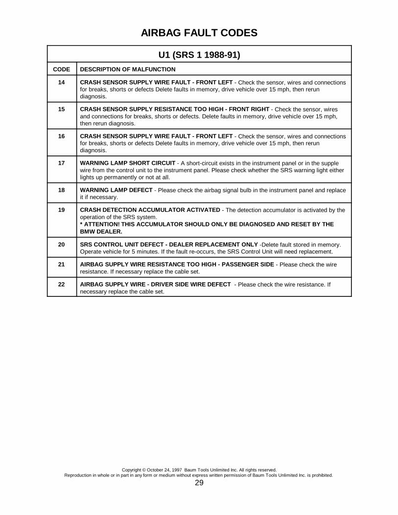
U1 (SRS 1 1988-91)CODE DESCRIPTION OF MALFUNCTION
Copyright © October 24, 1997 Baum Tools Unlimited Inc. All rights reserved.Reproduction in whole or in part in any form or medium without express written permission of Baum Tools Unlimited Inc. is prohibited.
29
14 CRASH SENSOR SUPPLY WIRE FAULT - FRONT LEFT - Check the sensor, wires and connectionsfor breaks, shorts or defects Delete faults in memory, drive vehicle over 15 mph, then rerundiagnosis.
15 CRASH SENSOR SUPPLY RESISTANCE TOO HIGH - FRONT RIGHT - Check the sensor, wiresand connections for breaks, shorts or defects. Delete faults in memory, drive vehicle over 15 mph,then rerun diagnosis.
16 CRASH SENSOR SUPPLY WIRE FAULT - FRONT LEFT - Check the sensor, wires and connectionsfor breaks, shorts or defects Delete faults in memory, drive vehicle over 15 mph, then rerundiagnosis.
17 WARNING LAMP SHORT CIRCUIT - A short-circuit exists in the instrument panel or in the supplewire from the control unit to the instrument panel. Please check whether the SRS warning light eitherlights up permanently or not at all.
18 WARNING LAMP DEFECT - Please check the airbag signal bulb in the instrument panel and replaceit if necessary.
19 CRASH DETECTION ACCUMULATOR ACTIVATED - The detection accumulator is activated by theoperation of the SRS system.* ATTENTION! THIS ACCUMULATOR SHOULD ONLY BE DIAGNOSED AND RESET BY THEBMW DEALER.
20 SRS CONTROL UNIT DEFECT - DEALER REPLACEMENT ONLY -Delete fault stored in memory.Operate vehicle for 5 minutes. If the fault re-occurs, the SRS Control Unit will need replacement.
21 AIRBAG SUPPLY WIRE RESISTANCE TOO HIGH - PASSENGER SIDE - Please check the wireresistance. If necessary replace the cable set.
22 AIRBAG SUPPLY WIRE - DRIVER SIDE WIRE DEFECT - Please check the wire resistance. Ifnecessary replace the cable set.
AIRBAG FAULT CODES
Copyright © October 24, 1997 Baum Tools Unlimited Inc. All rights reserved.Reproduction in whole or in part in any form or medium without express written permission of Baum Tools Unlimited Inc. is prohibited.
30
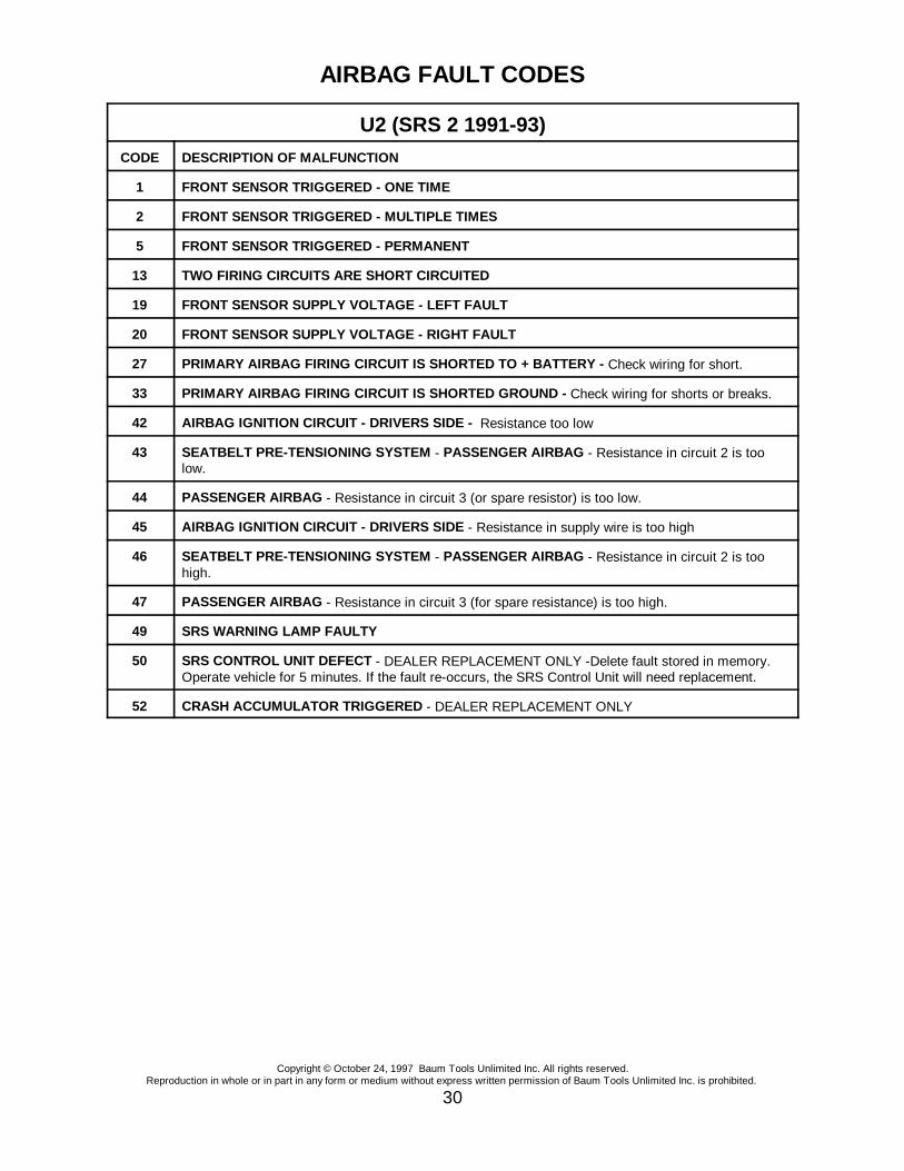
U2 (SRS 2 1991-93)CODE DESCRIPTION OF MALFUNCTION
1 FRONT SENSOR TRIGGERED - ONE TIME
2 FRONT SENSOR TRIGGERED - MULTIPLE TIMES
5 FRONT SENSOR TRIGGERED - PERMANENT
13 TWO FIRING CIRCUITS ARE SHORT CIRCUITED
19 FRONT SENSOR SUPPLY VOLTAGE - LEFT FAULT
20 FRONT SENSOR SUPPLY VOLTAGE - RIGHT FAULT
27 PRIMARY AIRBAG FIRING CIRCUIT IS SHORTED TO + BATTERY - Check wiring for short.
33 PRIMARY AIRBAG FIRING CIRCUIT IS SHORTED GROUND - Check wiring for shorts or breaks.
42 AIRBAG IGNITION CIRCUIT - DRIVERS SIDE - Resistance too low
43 SEATBELT PRE-TENSIONING SYSTEM - PASSENGER AIRBAG - Resistance in circuit 2 is toolow.
44 PASSENGER AIRBAG - Resistance in circuit 3 (or spare resistor) is too low.
45 AIRBAG IGNITION CIRCUIT - DRIVERS SIDE - Resistance in supply wire is too high
46 SEATBELT PRE-TENSIONING SYSTEM - PASSENGER AIRBAG - Resistance in circuit 2 is toohigh.
47 PASSENGER AIRBAG - Resistance in circuit 3 (for spare resistance) is too high.
49 SRS WARNING LAMP FAULTY
50 SRS CONTROL UNIT DEFECT - DEALER REPLACEMENT ONLY -Delete fault stored in memory.Operate vehicle for 5 minutes. If the fault re-occurs, the SRS Control Unit will need replacement.
52 CRASH ACCUMULATOR TRIGGERED - DEALER REPLACEMENT ONLY
AIRBAG FAULT CODES
Copyright © October 24, 1997 Baum Tools Unlimited Inc. All rights reserved.Reproduction in whole or in part in any form or medium without express written permission of Baum Tools Unlimited Inc. is prohibited.
31
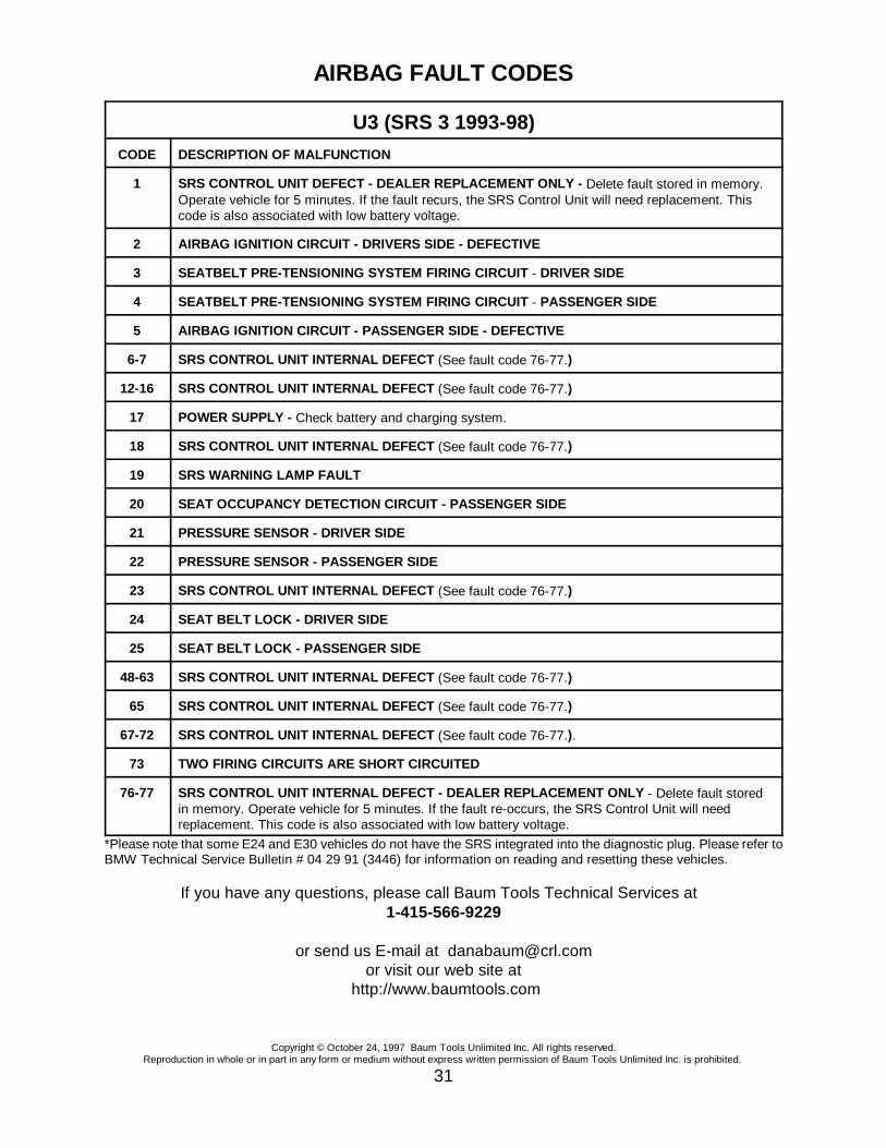
U3 (SRS 3 1993-98)CODE DESCRIPTION OF MALFUNCTION
1 SRS CONTROL UNIT DEFECT - DEALER REPLACEMENT ONLY - Delete fault stored in memory. Operate vehicle for 5 minutes. If the fault recurs, the SRS Control Unit will need replacement. Thiscode is also associated with low battery voltage.
2 AIRBAG IGNITION CIRCUIT - DRIVERS SIDE - DEFECTIVE
3 SEATBELT PRE-TENSIONING SYSTEM FIRING CIRCUIT - DRIVER SIDE
4 SEATBELT PRE-TENSIONING SYSTEM FIRING CIRCUIT - PASSENGER SIDE
5 AIRBAG IGNITION CIRCUIT - PASSENGER SIDE - DEFECTIVE
6-7 SRS CONTROL UNIT INTERNAL DEFECT (See fault code 76-77.)
12-16 SRS CONTROL UNIT INTERNAL DEFECT (See fault code 76-77.)
17 POWER SUPPLY - Check battery and charging system.
18 SRS CONTROL UNIT INTERNAL DEFECT (See fault code 76-77.)
19 SRS WARNING LAMP FAULT
20 SEAT OCCUPANCY DETECTION CIRCUIT - PASSENGER SIDE
21 PRESSURE SENSOR - DRIVER SIDE
22 PRESSURE SENSOR - PASSENGER SIDE
23 SRS CONTROL UNIT INTERNAL DEFECT (See fault code 76-77.)
24 SEAT BELT LOCK - DRIVER SIDE
25 SEAT BELT LOCK - PASSENGER SIDE
48-63 SRS CONTROL UNIT INTERNAL DEFECT (See fault code 76-77.)
65 SRS CONTROL UNIT INTERNAL DEFECT (See fault code 76-77.)
67-72 SRS CONTROL UNIT INTERNAL DEFECT (See fault code 76-77.).
73 TWO FIRING CIRCUITS ARE SHORT CIRCUITED
76-77 SRS CONTROL UNIT INTERNAL DEFECT - DEALER REPLACEMENT ONLY - Delete fault storedin memory. Operate vehicle for 5 minutes. If the fault re-occurs, the SRS Control Unit will needreplacement. This code is also associated with low battery voltage.
*Please note that some E24 and E30 vehicles do not have the SRS integrated into the diagnostic plug. Please refer toBMW Technical Service Bulletin # 04 29 91 (3446) for information on reading and resetting these vehicles.
If you have any questions, please call Baum Tools Technical Services at 1-415-566-9229
or send us E-mail at [email protected] visit our web site at
http://www.baumtools.com

Copyright © October 24, 1997 Baum Tools Unlimited Inc. All rights reserved.Reproduction in whole or in part in any form or medium without express written permission of Baum Tools Unlimited Inc. is prohibited.
32
**** Special Notes Regarding SRS Systems on E24 and E30 Ch assis
(For use with Baum Tools CS1000, Carsoft Software or BMW MODIC.)
On some E24 and E30 model BMWs, the RxD and TxD lines from the SRS control unit are notintegrated into the 20 pin diagnostic socket found under the hood. In order to diagnose and resetSRS lights on these vehicles, you must tap directly into the harness coming from the SRS controlunit.
Chassis Diagnostic Tool Plug Pin SRS Control Unit ConnectorE24 Pin #14 Battery (+) Battery (+) Terminal
Pin #15 (RxD) Pin #6 (WT/YL)Pin #19 Ground Good Vehicle GroundPin #20 (TxD) Pin #2 (WT/VI)
E30 Pin #14 Battery (+) Battery (+) TerminalPin #15 (RxD) Pin #6 (WT/YL)Pin #19 Ground Good Vehicle GroundPin #20 (TxD) Pin #2 (WT/VI)
E30 1992 Pin #14 Battery (+) Battery (+) TerminalConvertible Pin #15 (RxD) Pin #6 (WT/BLK)
Pin #19 Ground Good Vehicle GroundPin #20 (TxD) Pin #7 (WT/VI)
If using SRS reset tool #6213, 6214 or 621300 substitute pin #16 for pin #20.
Copyright © October 24, 1997 Baum Tools Unlimited Inc. All rights reserved.Reproduction in whole or in part in any form or medium without express written permission of Baum Tools Unlimited Inc. is prohibited.
33
SECTION 4 Transmission (EGS) Fault Code Lists
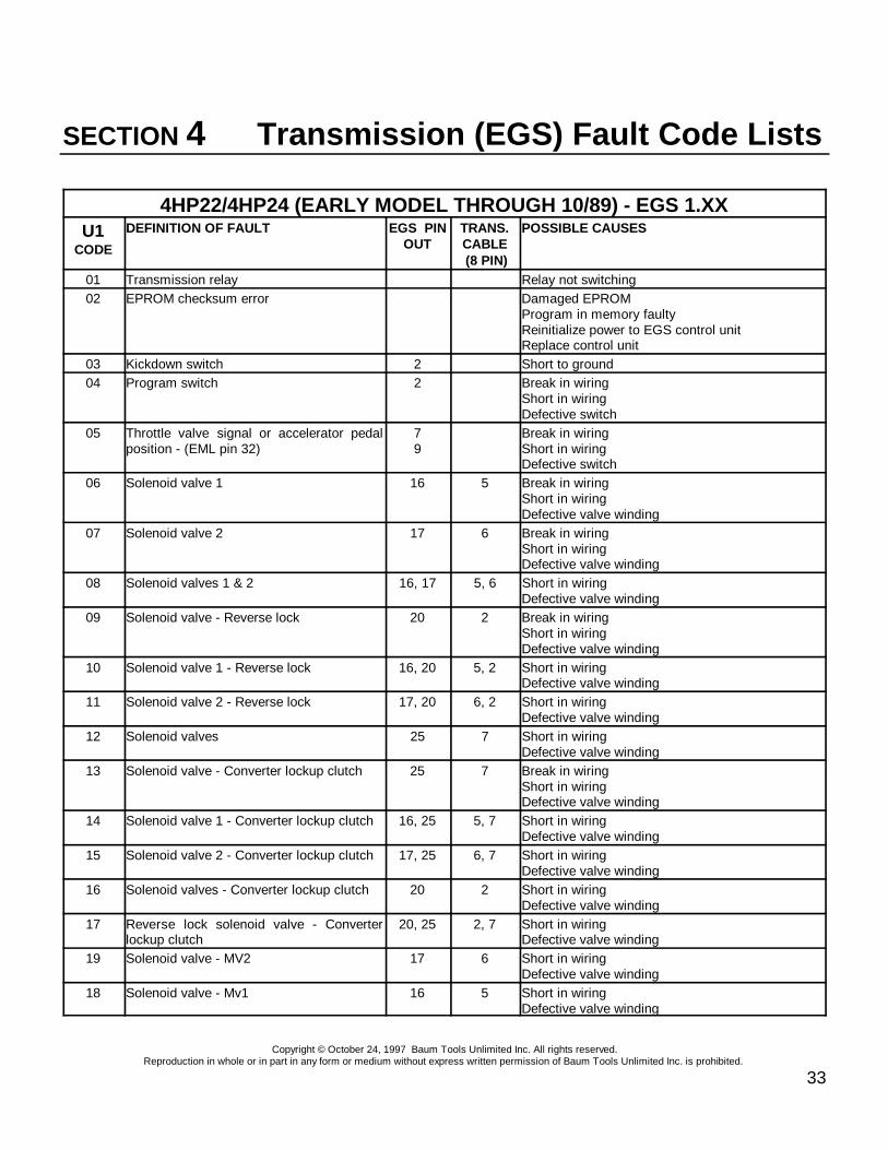
4HP22/4HP24 (EARLY MODEL THROUGH 10/89) - EGS 1.XXU1
CODE
DEFINITION OF FAULT EGS PINOUT
TRANS.CABLE (8 PIN)
POSSIBLE CAUSES
01 Transmission relay Relay not switching02 EPROM checksum error Damaged EPROM
Program in memory faultyReinitialize power to EGS control unitReplace control unit
03 Kickdown switch 2 Short to ground04 Program switch 2 Break in wiring
Short in wiringDefective switch
05 Throttle valve signal or accelerator pedalposition - (EML pin 32)
79
Break in wiringShort in wiringDefective switch
06 Solenoid valve 1 16 5 Break in wiringShort in wiringDefective valve winding
07 Solenoid valve 2 17 6 Break in wiringShort in wiringDefective valve winding
08 Solenoid valves 1 & 2 16, 17 5, 6 Short in wiringDefective valve winding
09 Solenoid valve - Reverse lock 20 2 Break in wiringShort in wiringDefective valve winding
10 Solenoid valve 1 - Reverse lock 16, 20 5, 2 Short in wiringDefective valve winding
11 Solenoid valve 2 - Reverse lock 17, 20 6, 2 Short in wiringDefective valve winding
12 Solenoid valves 25 7 Short in wiringDefective valve winding
13 Solenoid valve - Converter lockup clutch 25 7 Break in wiringShort in wiringDefective valve winding
14 Solenoid valve 1 - Converter lockup clutch 16, 25 5, 7 Short in wiringDefective valve winding
15 Solenoid valve 2 - Converter lockup clutch 17, 25 6, 7 Short in wiringDefective valve winding
16 Solenoid valves - Converter lockup clutch 20 2 Short in wiringDefective valve winding
17 Reverse lock solenoid valve - Converterlockup clutch
20, 25 2, 7 Short in wiringDefective valve winding
19 Solenoid valve - MV2 17 6 Short in wiringDefective valve winding
18 Solenoid valve - Mv1 16 5 Short in wiringDefective valve winding

4HP22/4HP24 (EARLY MODEL THROUGH 10/89) - EGS 1.XXU1
CODE
DEFINITION OF FAULT EGS PINOUT
TRANS.CABLE (8 PIN)
POSSIBLE CAUSES
Copyright © October 24, 1997 Baum Tools Unlimited Inc. All rights reserved.Reproduction in whole or in part in any form or medium without express written permission of Baum Tools Unlimited Inc. is prohibited.
34
20 Power supply - MV's and Pressure regulators 1 8 Short in wiringDefective valve winding
21 Engine speed sensor signal 21 Engine speed too high > 6800 rpm22 Pressure regulator 22 1 Break in wiring
Short in wiringDefective valve winding
23 Ignition timing intervention 24 Break in wiringShort to ground
24 Speed sensor n-ab - Downshift prevention 8, 27 3, 4 Break or short in wiring from control unit pin 8 tospeed sensorEngine speed sensor defective
25 Engine over-rev lock Engine speed exceeds output speed26 KVA signal (ti) 11 Fuel consumption indicator (KVA signal)27 Speed sensor n-ab Engine speed sensor or torque converter
or stall speed exceeded28 Breakdown display Transmission failure detected29 Incorrect checksum in EGS program
memoryDamaged EPROMProgram in memory faultyReinitialize power to EGS control unitReplace control unit
30 Battery voltage Battery voltage too low >9 voltsCheck batteryCheck charging system
31 Shift lever position 28200 Kickdown switch not working201 Kickdown switch fault202 Sport car transmission feature not selectable203 Manual shift program feature not selectable204 Program cannot be converted 6205 No engine deceleration detected 24206 False code set207 No EML detected300 Diagnostic circuit fault301 Voltage to control No voltage to EGS control unit
Check wiring harness302 Shift lever position sensor Break in wiring
Short in wiringDefective switch
303 Shift lever position sensor signal Break in wiringShort in wiringDefective switch

Copyright © October 24, 1997 Baum Tools Unlimited Inc. All rights reserved.Reproduction in whole or in part in any form or medium without express written permission of Baum Tools Unlimited Inc. is prohibited.
35
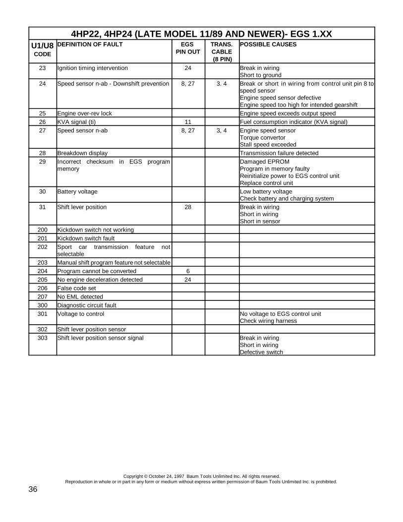
4HP22, 4HP24 (LATE MODEL 11/89 AND NEWER)- EGS 1.XXU1/U8CODE
DEFINITION OF FAULT EGS PIN OUT
TRANS.CABLE (8 PIN)
POSSIBLE CAUSES
01 Transmission relay Relay in EGS not switching02 EPROM checksum error Damaged EPROM
Program in memory faultyReinitialize power to EGS control unitReplace control unit
03 Kickdown switch 2 Short to ground04 Program switch
E=pin 14, M=pin 15, S=pin 4Break in wiringShort in wiringDefective switch
05 Throttle valve signal or accelerator pedalposition - (EML pin 32)
7, 9 Break in wiringShort in wiringDefective switch
06 Solenoid valve 1 16 5 Break in wiringShort in wiringDefective valve winding
07 Solenoid valve 2 17 6 Break in wiringShort in wiringDefective valve winding
08 Solenoid valves 1 & 2 16, 17 5, 6 Short in wiringDefective valve winding
09 Solenoid valve -Park/neutral lock 20 2 Break in wiringShort in wiringDefective valve winding
10 Solenoid valve 1 - Park/neutral lock 16, 20 5, 2 Short in wiringDefective valve winding
11 Solenoid valve 2 - Park/neutral lock 17, 20 6, 2 Short in wiringDefective valve winding
12 Solenoid valves 25 7 Short in wiringDefective valve winding
13 Solenoid valve - Converter lockup clutch 25 7 Break in wiringShort in wiringDefective valve winding
14 Solenoid valve 1 - Converter lockup clutch 16, 25 5, 7 Short in wiringDefective valve winding
15 Solenoid valve 2 - Converter lockup clutch 17, 25 6, 7 Short in wiringDefective valve winding
16 Solenoid valves - Converter lockup clutch 20 2 Short in wiringDefective valve winding
17 Reverse lock solenoid valve - Converterlockup clutch
20, 25 2, 7 Short in wiringDefective valve winding
19 Solenoid valve - Magnetic valve 2 17 6 Short in wiringDefective valve winding
18 Solenoid valve - Magnetic valve 1 16 5 Short in wiringDefective valve winding
20 Power supply - Solenoid valves (MV’s) andPressure regulators
1 8 Break in wiringShort in wiringDefective valve winding
21 Engine speed sensor signal 21 Engine speed too high > 6800 rpm22 Pressure regulator 22 1 Break in wiring
Short in wiringDefective valve winding
4HP22, 4HP24 (LATE MODEL 11/89 AND NEWER)- EGS 1.XXU1/U8CODE
DEFINITION OF FAULT EGS PIN OUT
TRANS.CABLE (8 PIN)
POSSIBLE CAUSES
Copyright © October 24, 1997 Baum Tools Unlimited Inc. All rights reserved.Reproduction in whole or in part in any form or medium without express written permission of Baum Tools Unlimited Inc. is prohibited.
36
23 Ignition timing intervention 24 Break in wiringShort to ground
24 Speed sensor n-ab - Downshift prevention 8, 27 3. 4 Break or short in wiring from control unit pin 8 tospeed sensorEngine speed sensor defectiveEngine speed too high for intended gearshift
25 Engine over-rev lock Engine speed exceeds output speed26 KVA signal (ti) 11 Fuel consumption indicator (KVA signal)27 Speed sensor n-ab 8, 27 3, 4 Engine speed sensor
Torque convertorStall speed exceeded
28 Breakdown display Transmission failure detected29 Incorrect checksum in EGS program
memoryDamaged EPROMProgram in memory faultyReinitialize power to EGS control unitReplace control unit
30 Battery voltage Low battery voltageCheck battery and charging system
31 Shift lever position 28 Break in wiringShort in wiringShort in sensor
200 Kickdown switch not working201 Kickdown switch fault202 Sport car transmission feature not
selectable203 Manual shift program feature not selectable204 Program cannot be converted 6205 No engine deceleration detected 24206 False code set207 No EML detected300 Diagnostic circuit fault301 Voltage to control No voltage to EGS control unit
Check wiring harness302 Shift lever position sensor303 Shift lever position sensor signal Break in wiring
Short in wiringDefective switch
Copyright © October 24, 1997 Baum Tools Unlimited Inc. All rights reserved.Reproduction in whole or in part in any form or medium without express written permission of Baum Tools Unlimited Inc. is prohibited.
37
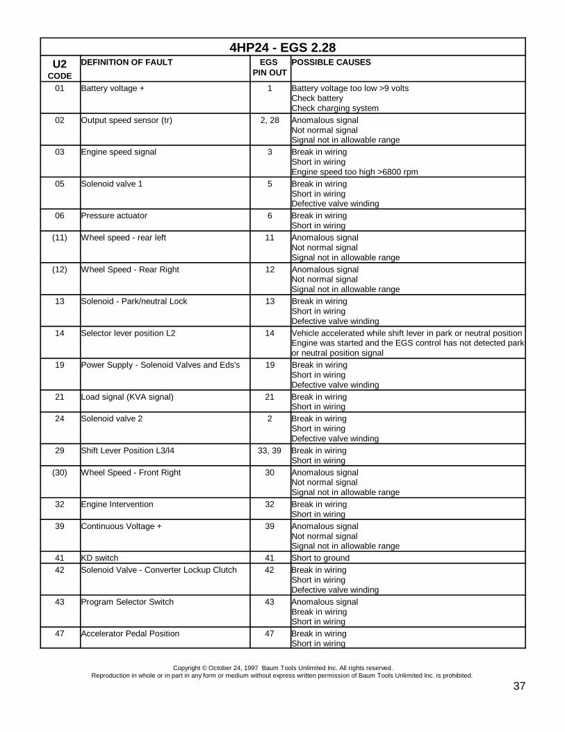
4HP24 - EGS 2.28U2
CODE
DEFINITION OF FAULT EGS PIN OUT
POSSIBLE CAUSES
01 Battery voltage + 1 Battery voltage too low >9 voltsCheck batteryCheck charging system
02 Output speed sensor (tr) 2, 28 Anomalous signalNot normal signalSignal not in allowable range
03 Engine speed signal 3 Break in wiringShort in wiringEngine speed too high >6800 rpm
05 Solenoid valve 1 5 Break in wiringShort in wiringDefective valve winding
06 Pressure actuator 6 Break in wiringShort in wiring
(11) Wheel speed - rear left 11 Anomalous signalNot normal signalSignal not in allowable range
(12) Wheel Speed - Rear Right 12 Anomalous signalNot normal signalSignal not in allowable range
13 Solenoid - Park/neutral Lock 13 Break in wiringShort in wiringDefective valve winding
14 Selector lever position L2 14 Vehicle accelerated while shift lever in park or neutral positionEngine was started and the EGS control has not detected parkor neutral position signal
19 Power Supply - Solenoid Valves and Eds's 19 Break in wiringShort in wiringDefective valve winding
21 Load signal (KVA signal) 21 Break in wiringShort in wiring
24 Solenoid valve 2 2 Break in wiringShort in wiringDefective valve winding
29 Shift Lever Position L3/l4 33, 39 Break in wiringShort in wiring
(30) Wheel Speed - Front Right 30 Anomalous signalNot normal signalSignal not in allowable range
32 Engine Intervention 32 Break in wiringShort in wiring
39 Continuous Voltage + 39 Anomalous signalNot normal signalSignal not in allowable range
41 KD switch 41 Short to ground42 Solenoid Valve - Converter Lockup Clutch 42 Break in wiring
Short in wiringDefective valve winding
43 Program Selector Switch 43 Anomalous signalBreak in wiringShort in wiring
47 Accelerator Pedal Position 47 Break in wiringShort in wiring
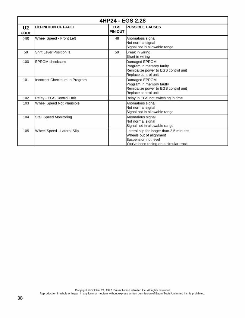
4HP24 - EGS 2.28U2
CODE
DEFINITION OF FAULT EGS PIN OUT
POSSIBLE CAUSES
Copyright © October 24, 1997 Baum Tools Unlimited Inc. All rights reserved.Reproduction in whole or in part in any form or medium without express written permission of Baum Tools Unlimited Inc. is prohibited.
38
(48) Wheel Speed - Front Left 48 Anomalous signalNot normal signalSignal not in allowable range
50 Shift Lever Position l1 50 Break in wiringShort in wiring
100 EPROM checksum Damaged EPROMProgram in memory faultyReinitialize power to EGS control unitReplace control unit
101 Incorrect Checksum in Program Damaged EPROMProgram in memory faultyReinitialize power to EGS control unitReplace control unit
102 Relay - EGS Control Unit Relay in EGS not switching in time103 Wheel Speed Not Plausible Anomalous signal
Not normal signalSignal not in allowable range
104 Stall Speed Monitoring Anomalous signalNot normal signalSignal not in allowable range
105 Wheel Speed - Lateral Slip Lateral slip for longer than 2.5 minutesWheels out of alignmentSuspension not levelYou've been racing on a circular track

Copyright © October 24, 1997 Baum Tools Unlimited Inc. All rights reserved.Reproduction in whole or in part in any form or medium without express written permission of Baum Tools Unlimited Inc. is prohibited.
39
A4S 310R (THM-R1), A4S 270R (THM-R1) - EGS 4.XXU4
CODE
DEFINITION OF FAULT EGS PIN OUT
POSSIBLE CAUSES
01 Solenoid Parking/neutral lock Break in wiringShort in wiringDefective valve winding
02 Program SWITCHE=pin 2, M=pin 31, S=pin 34
Break in wiringShort in wiringDefective switch
04 Engine Intervention 4 Break in wiringShort in wiring
09 KVA Signal (ti) 9 Break in wiringShort in wiring
11 Engine Speed Signal (n-mot) 11 Break in wiringShort in wiring
20 Transmission rotation speed signal (n-ab) -Stall speed signal
14, 20 No signalAnomalous engine speed signal
22 Transmission fluid temperature sensor 17, 22 Transmission temperature too high (>165c)23 Shift Lever Position 26 Break in wiring
Short in wiringShort in sensor
28 Battery Voltage + (Terminal 30) 28 Break in wiringCheck battery contacts and wiring integrity
30 Kickdown Switch 30 Short to ground35 Stop Light Switch 35 Break in wiring37 Battery voltage + 37 Voltage out of range38 Solenoid valve - Converter lockup clutch 38 Break in wiring
Short in wiringDefective valve winding
39 Stop light switch 39 Break in wiring40 Pressure regulator 40, 41 Break in wiring
Short in wiringDefective valve winding
43 Solenoid valve 2 43 Break in wiringShort in wiringDefective valve winding
45 Solenoid valve - Band 45 Break in wiringShort in wiringDefective valve winding
48 Solenoid valve 1 48 Break in wiringShort in wiringDefective valve winding
54 Ground - Solenoid valves 54 Break in wiringShort in wiringDefective valve winding
55 Throttle valve signal (DKT) 55 Anomalous throttle valve signalBreak in wiringShort in wiring
100 Speed monitoring Speed ratio n-ab/n-mot not correct for gear selected101 Downshift lock Speed too high for downshift intended102 Engine over-rev lock in 1st and 2nd gear Engine sped 300 rpm above output speed103 EPROM error Damaged EPROM
Program in memory faultyReinitialize power to EGS control unitReplace control unit

A4S 310R (THM-R1), A4S 270R (THM-R1) - EGS 4.XXU4
CODE
DEFINITION OF FAULT EGS PIN OUT
POSSIBLE CAUSES
Copyright © October 24, 1997 Baum Tools Unlimited Inc. All rights reserved.Reproduction in whole or in part in any form or medium without express written permission of Baum Tools Unlimited Inc. is prohibited.
40
104 DKT engine temperature signal 35105 DKT throttle valve signal 35 Break in wiring
Short in wiringAnomalous signal
107 False code set110 EGS control unit not programmed Have EGS control unit programmed105 DKT throttle valve signal 35 Break in wiring short in wiring
Anomalous throttle valve signal106 MUX injection rate DDE sending faulty injection rate signal110 EGS control unit not programmed Have EGS control unit programmed
(150) Can timeout 1 Can signal not sent during engine start (ignition on)(151) Can timeout 2 Can signal not detected (engine running)(152) Can bus monitor Values in can ram storage not updated(153) Can status fault Control units with different can status' are installed on the same
busReplace with correct units
(154) Can throttle valve signal Anomalous throttle valve signal detected by DME(155) Can load signal Anomalous load signal detected by DME(156) Can engine intervention DME cannot alter engine torque to match EGS signal
DME does not match other can control units(157) Can engine temperature Anomalous engine temperature signal detected by DME(158) Can engine speed signal Anomalous engine speed signal detected by DME200 Kickdown not working201 Sport car transmission feature not selectable202 Manual shift program feature not selectable203 Program cannot be converted 6204 No engine deceleration detected 24205 Brake light
Brake light test switch206 False code set 25300 Diagnostic circuit fault301 EGS voltage supply No voltage to EGS control unit
Check wiring harness

Copyright © October 24, 1997 Baum Tools Unlimited Inc. All rights reserved.Reproduction in whole or in part in any form or medium without express written permission of Baum Tools Unlimited Inc. is prohibited.
41
A5S 310Z (5HP-18) - EGS 7.XXU7
CODE
DEFINITION OF FAULT EGS PINOUT
POSSIBLE CAUSES
02 Solenoid Parking/Neutral lock 2 Break in wiringShort in wiringDefective valve winding
03 Solenoid valve 5 Break in wiringShort in wiringDefective valve winding
04 Solenoid valve 6 - Convertor lockup clutch Break in wiringShort in wiringDefective valve winding
05 Pressure regulator Break in wiringShort in wiringDefective valve winding
08 Shift Lever Position L2 8 Vehicle accelerated while shift lever in park or neutral positionEngine was started and the EGS control has not detected parkor neutral position signal
09 Shift lever position L3/L4 37, 9 Break in wiringShort in wiringShort in sensor
12 Program selector switch 12, 13,45
Short to ground
16 Turbo charger speed sensor 16, 44 No signalAnomalous engine speed signal
18 Kickdown switch 18 Short to groundAnomalous signal
19 ASC monitoring 19 Break in wiringShort in wiringEGS detected anomalous ASC signalASC operation detected while shift lever in park or neutral
22 ATF sump temperature sensor 21, 22 Break in wiringShort in wiring
26 Battery voltage + 26 Break in wiringCheck batteryCheck charging system
30 Solenoid valve 1 30 Break in wiringShort in wiringDefective valve winding
31 Solenoid valve 4 31 Break in wiringShort in wiringDefective valve winding
32 Solenoid valve 3 32 Break in wiringShort in wiringDefective valve winding
33 Solenoid valve 2 33 Break in wiringShort in wiringDefective valve winding
35 Throttle valve signal (DKT) 35 Break in wiringShort in wiringAnomalous throttle valve signal
36 Shift lever position l1 36 Break in wiringShort in wiringShort in sensor
40 Engine intervention 40 Break in wiringShort in wiring

A5S 310Z (5HP-18) - EGS 7.XXU7
CODE
DEFINITION OF FAULT EGS PINOUT
POSSIBLE CAUSES
Copyright © October 24, 1997 Baum Tools Unlimited Inc. All rights reserved.Reproduction in whole or in part in any form or medium without express written permission of Baum Tools Unlimited Inc. is prohibited.
42
41 KVA signal 41 Break in wiringShort in wiring
42 Transmission output rotation speed signal (n-ab)- Stall speed signal
14, 42 No signalAnomalous engine speed signal
43 Engine speed signal (n-mot) 43 No signalAnomalous engine speed signal
53 Power supply - Solenoid valves 53 Relay in EGS not switching54 Batter voltage + 54 Battery voltage too low (>9 volts)
Check batteryCheck charging system
100 Speed monitoring Trans/engine speed ratio not correct for gear selectedSpeed sensor signal faultySlip in transmission too high
101 EPROM checksum error Damaged EPROMProgram in memory faultyReinitialize power to EGS control unitReplace control unit
102 Program checksum error Damaged EPROMProgram in memory faultyReinitialize power to EGS control unitReplace control unit
103 Relay - EGS control unit Relay in EGS not switching in time104 DKT- Temperature signal 35 Break in wiring short in wiring
Anomalous engine temperature signal105 DKT - Throttle valve signal 35 Break in wiring short in wiring
Anomalous throttle valve signal106 MUX injection rate DDE sending faulty injection rate signal110 EGS control unit not programmed Have EGS control unit programmed
(150) CAN timeout 1 CAN signal not sent during engine start (ignition on)(151) CAN timeout 2 CAN signal not detected (engine running)(152) CAN bus monitor Values in CAN ram storage not updated(153) CAN status fault Control units with different CAN status' are installed on the
same busReplace with correct units
(154) CAN throttle valve signal Anomalous throttle valve signal detected by DME(155) CAN load signal Anomalous load signal detected by DME(156) CAN engine intervention DME cannot alter engine torque to match EGS signal
DME does not match other CAN control units(157) CAN engine temperature Anomalous engine temperature signal detected by DME(158) CAN engine speed signal Anomalous engine speed signal detected by DME200 Kickdown not working201 Sport car transmission feature not selectable202 Manual shift program feature not selectable203 Program cannot be converted 6204 No engine deceleration detected 24205 Brake light
Brake light test switch206 False code set300 Diagnostic circuit fault301 EGS voltage supply No voltage to EGS control unit
Check wiring harness

Copyright © October 24, 1997 Baum Tools Unlimited Inc. All rights reserved.Reproduction in whole or in part in any form or medium without express written permission of Baum Tools Unlimited Inc. is prohibited.
43
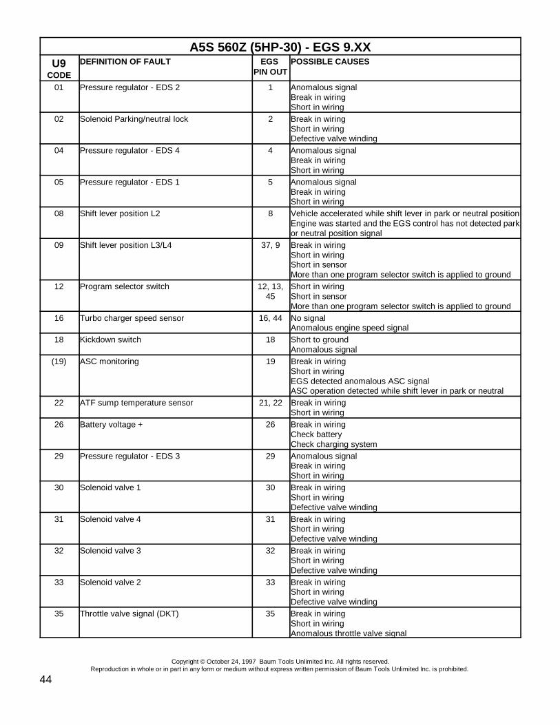
Copyright © October 24, 1997 Baum Tools Unlimited Inc. All rights reserved.Reproduction in whole or in part in any form or medium without express written permission of Baum Tools Unlimited Inc. is prohibited.
44
A5S 560Z (5HP-30) - EGS 9.XXU9
CODE
DEFINITION OF FAULT EGS PIN OUT
POSSIBLE CAUSES
01 Pressure regulator - EDS 2 1 Anomalous signalBreak in wiringShort in wiring
02 Solenoid Parking/neutral lock 2 Break in wiringShort in wiringDefective valve winding
04 Pressure regulator - EDS 4 4 Anomalous signalBreak in wiringShort in wiring
05 Pressure regulator - EDS 1 5 Anomalous signalBreak in wiringShort in wiring
08 Shift lever position L2 8 Vehicle accelerated while shift lever in park or neutral positionEngine was started and the EGS control has not detected parkor neutral position signal
09 Shift lever position L3/L4 37, 9 Break in wiringShort in wiringShort in sensorMore than one program selector switch is applied to ground
12 Program selector switch 12, 13,45
Short in wiringShort in sensorMore than one program selector switch is applied to ground
16 Turbo charger speed sensor 16, 44 No signalAnomalous engine speed signal
18 Kickdown switch 18 Short to groundAnomalous signal
(19) ASC monitoring 19 Break in wiringShort in wiringEGS detected anomalous ASC signalASC operation detected while shift lever in park or neutral
22 ATF sump temperature sensor 21, 22 Break in wiringShort in wiring
26 Battery voltage + 26 Break in wiringCheck batteryCheck charging system
29 Pressure regulator - EDS 3 29 Anomalous signalBreak in wiringShort in wiring
30 Solenoid valve 1 30 Break in wiringShort in wiringDefective valve winding
31 Solenoid valve 4 31 Break in wiringShort in wiringDefective valve winding
32 Solenoid valve 3 32 Break in wiringShort in wiringDefective valve winding
33 Solenoid valve 2 33 Break in wiringShort in wiringDefective valve winding
35 Throttle valve signal (DKT) 35 Break in wiringShort in wiringAnomalous throttle valve signal
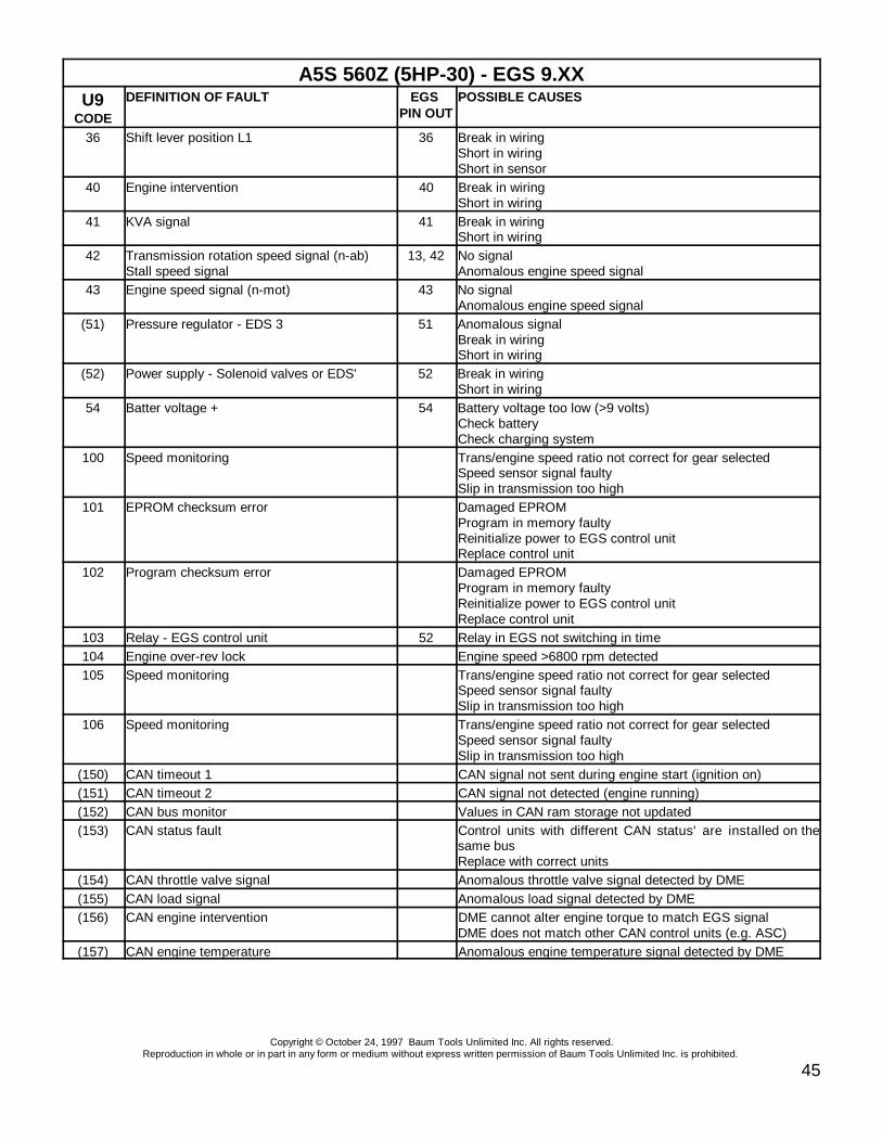
A5S 560Z (5HP-30) - EGS 9.XXU9
CODE
DEFINITION OF FAULT EGS PIN OUT
POSSIBLE CAUSES
Copyright © October 24, 1997 Baum Tools Unlimited Inc. All rights reserved.Reproduction in whole or in part in any form or medium without express written permission of Baum Tools Unlimited Inc. is prohibited.
45
36 Shift lever position L1 36 Break in wiringShort in wiringShort in sensor
40 Engine intervention 40 Break in wiringShort in wiring
41 KVA signal 41 Break in wiringShort in wiring
42 Transmission rotation speed signal (n-ab)Stall speed signal
13, 42 No signalAnomalous engine speed signal
43 Engine speed signal (n-mot) 43 No signalAnomalous engine speed signal
(51) Pressure regulator - EDS 3 51 Anomalous signalBreak in wiringShort in wiring
(52) Power supply - Solenoid valves or EDS' 52 Break in wiringShort in wiring
54 Batter voltage + 54 Battery voltage too low (>9 volts)Check batteryCheck charging system
100 Speed monitoring Trans/engine speed ratio not correct for gear selectedSpeed sensor signal faultySlip in transmission too high
101 EPROM checksum error Damaged EPROMProgram in memory faultyReinitialize power to EGS control unitReplace control unit
102 Program checksum error Damaged EPROMProgram in memory faultyReinitialize power to EGS control unitReplace control unit
103 Relay - EGS control unit 52 Relay in EGS not switching in time104 Engine over-rev lock Engine speed >6800 rpm detected105 Speed monitoring Trans/engine speed ratio not correct for gear selected
Speed sensor signal faultySlip in transmission too high
106 Speed monitoring Trans/engine speed ratio not correct for gear selectedSpeed sensor signal faultySlip in transmission too high
(150) CAN timeout 1 CAN signal not sent during engine start (ignition on)(151) CAN timeout 2 CAN signal not detected (engine running)(152) CAN bus monitor Values in CAN ram storage not updated(153) CAN status fault Control units with different CAN status' are installed on the
same busReplace with correct units
(154) CAN throttle valve signal Anomalous throttle valve signal detected by DME(155) CAN load signal Anomalous load signal detected by DME(156) CAN engine intervention DME cannot alter engine torque to match EGS signal
DME does not match other CAN control units (e.g. ASC)(157) CAN engine temperature Anomalous engine temperature signal detected by DME

Copyright © October 24, 1997 Baum Tools Unlimited Inc. All rights reserved.Reproduction in whole or in part in any form or medium without express written permission of Baum Tools Unlimited Inc. is prohibited.
46
BMW ACRONYMSA/D Analog/DigitalAB Supplemental Restraint System (Airbag)ABS Anti-lock Brake SystemAEGS Electronic Automatic Transmission SystemAG Automatic TransmissionASC Automatic Stability ControlCAN Control Area Network (Multiple ECU controller)CANP Tank Ventilation ValveCO Carbon MonoxideDDE Digital Diesel Electronics (Diesel ECU)DK Throttle ValveDKB Throttle-Brake InterventionDKE Throttle IncreaseDKR Throttle reductionDKT Throttle Valve SignalDKV Preset Throttle ValueDME Digital Motor Electronics (Gas ECU)DWA Antitheft SystemECU Electronic Control UnitEDS Pressure RegulatorEGS Electronic Transmission Control (Trans, ECU)EH Electrohydraulic TransmissionEKM Electronic Body ModuleEKP Fuel Pump RelayEML Electronic Throttle ControlEPROM Erasable/Programmable Read Only MemoryEV Injector ValveHG Manual TransmissionHLM Hot-Wire Air Mass MeterHz Hertz (Cycle)ISC Idle Speed ControlKD Kick-down (Auto Downshift on Acceleration)KVA Fuel Consumption SignalLL IdleLMM Air Flow MeterMSR Engine Drag Torque ControlMV Magnetic Valve (Solenoid Valve)n-ab Transmission Rotational Speed (RPM)n-mot Engine Rotational Speed P/N Park/NeutralPWG Pedal Position SensorRAM Random Access MemoryRXD Receive Data LineSG Control UnitTD Engine Speed Signal (Once per ignition)TDC Top Dead CenterTE Fuel Evaporation Controlti Injection TimingtL Load SignalTR Engine Speed Signal (Rpm Counter)TXD Transmit Data LineU-Batt Battery VoltageU-Vers Supply VoltageVL Full LoadWK Torque Convertor ClutchZAB Ignition Fade-Out

Copyright © October 24, 1997 Baum Tools Unlimited Inc. All rights reserved.Reproduction in whole or in part in any form or medium without express written permission of Baum Tools Unlimited Inc. is prohibited.
47
BMW CHASSIS DESIGNATIONS
Production Cars - Past and Current Models That Have Been Put into Production .
CHASSIS YEAR MODEL BODY STYLE114 1967-75 1502/1602/1802/2002Tii 2d sedan115 1962-64 1500 4d sedan116 1600 4d sedan118 1963-? 1800/1800Ti/1800TiSA 4d sedan120 1966-? 2000/2000Ti/2000TiLUX/2000Tii 4d sedan121 1965-69 2000C/2000CS Tii 2d coupeE3 2500 - 3.3Li Bavaria' 4d sedanE6 1600/1800/2000/2000/Tii touring 2d coupe/3d hatchE9 1972-75 2.5CS - 3.0CSL 2d coupeE10 1972-74 2002ti/2002tii 2d coupeE12 1973-81 5-series (4 cylinder) 4d sedanE12/5 1973-81 5-series (small 6 cylinder) 4d sedanE12/6 1973-81 5-series (large 6 cylinder) 4d sedan - South AfricanE12/8 1973-81 5-series 4d sedan - South AfricanE20 1973-74 2002 turbo 2d coupeE21 1976-82 3-series 2d coupeE21/5 3 series (small 6 cylinder) 2d coupeE23 1978-86 7-series 4d sedanE24 1976-89 6-series (628-635CSi/M6) 2d coupeE26 1979-80 M1 with M88 engine 2d mid-engine coupeE28 1982-87 5-series 4d sedanE30 1983-90 3-series 2d coupe/4d sedan/ convertibleE30/5 1987-90 3-series 'Touring' 5d wagonE30/16 1987-90 3-series iX 2d coupe/4d sedan (4WD)E31 1990- 8-series 2d coupeE32 1987-94 7-series 4d sedanE32/2 1987-94 7-series 4d sedan LWBE34 1988-94 5-series 4d sedanE34/2 1989-94 5-series 5d wagonE36 1991- 3-series 4d sedanE36/2 1992- 3-series see-above 2d coupe/convertibleE36/5 1994- 3-series 'Compact' 3d hatchE36/6 1995- 3-series 'Touring' 5d wagonE36/7 1996- Z3 2d roadster - U.S. madeE37/8 1997? Z3 coupe 3d hatchback - U.S. madeE38 1995- 7-series 4d sedanE38/2 1995- 7-series 4d sedan LWBE39 1996- 5-series 4d sedanE46 1998- 3-series 4d sedan/2d coupe/convertibleZ1 1987-91 plastic-body roadster 2d convertible
Show Cars - Concept Cars That Have Been Displayed at Various Auto Shows.E1/E2 1992/93 Electric Prototypes 3d hatchZ13 1993 Hybrid City Car 3d hatch
Rumors/Speculation - Not Yet (maybe never) in Production, Development, Testing .E45 1999? 2-series sedan/hatch/wagon/offroader
(E1 derivative) FWD/Aluminum spaceframeE51 1999? Reborn 6-series (based on E39) 2d coupe/convertible?E52 1998? Modern 507 roadster 2d convertible
(low volume, high $)
Copyright © October 24, 1997 Baum Tools Unlimited Inc. All rights reserved.Reproduction in whole or in part in any form or medium without express written permission of Baum Tools Unlimited Inc. is prohibited.
48
E53 1999? Sport-Utility !? SUV/minivan/wagon hybrid

Copyright © October 24, 1997 Baum Tools Unlimited Inc. All rights reserved.Reproduction in whole or in part in any form or medium without express written permission of Baum Tools Unlimited Inc. is prohibited.
49
BMW ENGINE DESIGNATIONS
ENGINE DISP. CYLINDERS CHASSISM10 1.8 SOHC-8v/L4 E21M12/6 2.0 DOHC-16v/L4 Formula 2M12/7 2.0 DOHC-16v/L4 F2/320i Group 5M12/9 2.0 DOHC-16v/L4 Turbo 320i Group 5M13 1.5 DOHC-16v/L4 Turbo Formula 1M20 2.5/2.7 SOHC-12v/L6 + eta E28/E30/E34M21 2.4 SOHC-12v/L6 Diesel E28/E30/E34/E36M30 3.0/3.2/3.3/3.5 SOHC-12v/L6 E23/E24/E28/E32M40 1.6/1.8 SOHC-8v/L4 E30/E36M42 1.8 DOHC-16v/L4 E30/E34/E36
?-->1.9 + Al block/VANOSM43 1.8 SOHC-8v/L4 E36M50 2.0/2.5 DOHC-24v/L6 E34/E36M50TU 2.0/2.5 DOHC-24v/L6 w/VANOS E34/E36M52 2.0/2.3/2.8 DOHC-24v/L6 w/VANOS E36/E39
(Al block)M60 (old) 2.0/2.3 SOHC-12v/L6 Carbureted E12/E21M60 3.0/4.0 DOHC-32v/V8 E31/E32/E34/E38/E39M62 3.0/4.0 DOHC-32v/V8 E31/E34/E38/E39M70 5.0/5.4/5.6 SOHC-24v/V12 E31/E32/E38M73 5.0 SOHC-48v/V12 E38M88 3.5 DOHC-24v/L6 E26-M1M88/1 3.5 DOHC-24v/L6 Group 4 (470hp)M88/2 3.5 DOHC-24v/L6 Group 4 (850hp)M88/3 3.5 DOHC-24v/L6 E24-early M5/M6M102 3.2/3.5 SOHC-12v/L6 Turbo E23-745i TurboS14 2.3/2.5 DOHC-16v/L4 E30-M3S38 3.5/3.6/3.8 DOHC-24v/L6 E28-M5/E24-M6/E34-M5S50 3.0 DOHC-24v/L6 E36-M3S50US 3.0 DOHC-24v/L6 E36-M3 U.S. vers.S70/2 6.1 DOHC-48v/V12 McLaren F1
BMW EGS MODELS 1987-95
TRANSMISSION TYPE EGS SYSTEM
4HP 22/4HP 24 ( TO 11/89) 1.XX
4HP 22/4HP 24 ( 11/89-newer) 1.XX
4HP 24 (non-U.S. 850CSi) 2.28
A4S 310R (THM-R1) 4.XX
A4S 270Z (THM-R1) 4.XX
A5S 310Z (5HP-18) 7.XX
A5S 560Z (5HP-30) 9.XX