csci 5561: assignment #5 stereo reconstruction 1 submissionhspark/csci5561_s2019/hw5.pdf · csci...
TRANSCRIPT
CSCI 5561: Assignment #5
Stereo Reconstruction
1 Submission
• Assignment due: May 10 (11:55pm)
• Individual assignment
• Up to 2 page summary write-up with resulting visualization (more than 2 pageassignment will be automatically returned.).
• Submission through Canvas.
• Provided codes and data can be downloaded from:https://www-users.cs.umn.edu/~hspark/csci5561/HW5.zip. It contains thefollowing three codes and image data:
– main_stereo.m
– ComputeCameraPose.m
– WarpImage.m
– left.bmp
– right.bmp
• List of submission codes:
– main_stereo.m
– FindMatch.m
– ComputeF.m
– Triangulation.m
– DisambiguatePose.m
– ComputeRectification.m
– DenseMatch.m
• A MAT file that contains the following trained weights:
– stereo.mat: x1, x2, F, X, H1, H2, im1_w, im2_w, disp
• DO NOT SUBMIT THE PROVIDED IMAGE DATA
• The function that does not comply with its specification will not be graded.
• You are allowed to use MATLAB built-in functions except for the ones in theComputer Vision Toolbox. Please consult with TA if you are not sure about thelist of allowed functions.
1
CSCI 5561: Assignment #5
Stereo Reconstruction
2 Overview
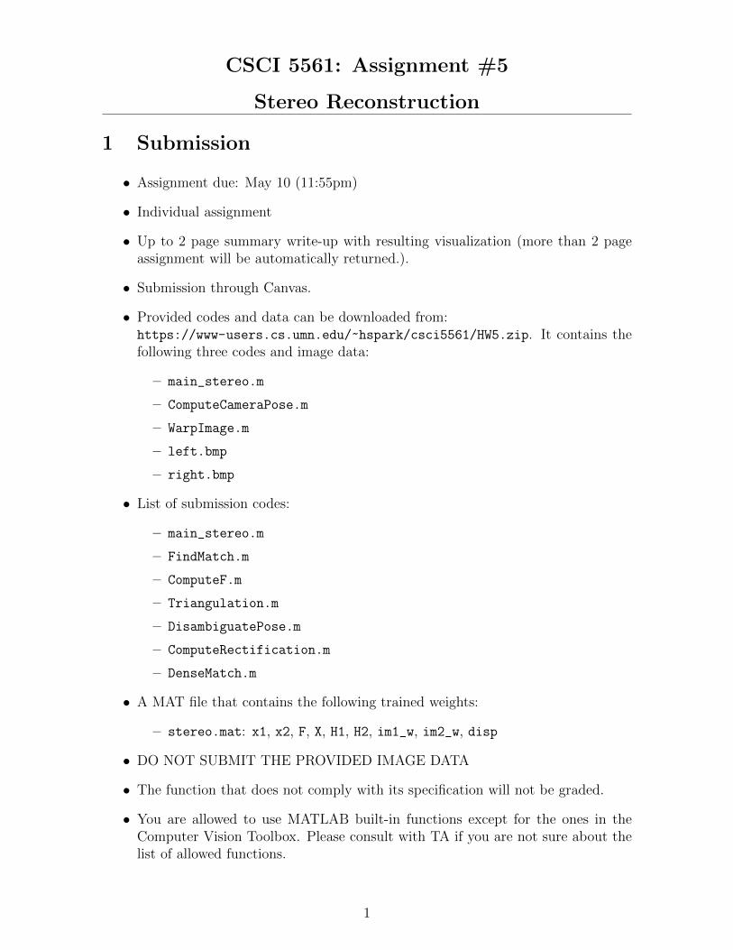
In this assignment, you will implement a stereo reconstruction algorithm given two viewimages.
(a) Left image (b) Right image
Figure 1: In this assignment, you will implement a stereo reconstruction algorithmgiven two images.
You can download the skeletal code and data (left.bmp and right.bmp) from here:https://www-users.cs.umn.edu/~hspark/csci5561/HW5.zip
You will fill main_stereo.m that takes input images and intrinsic parameters K, andproduces a stereo disparity map.
2
CSCI 5561: Assignment #5
Stereo Reconstruction
3 SIFT Feature Matching
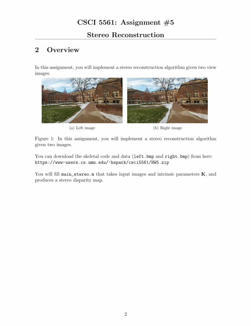
(a) Matching from I1 to I2 (b) Matching from I2 to I1
(c) Matching from I1 to I2 after ratio test (d) Matching from I2 to I1 after ratio test
(e) Bidirectional matching between I1 and I2
Figure 2: You will match points between I1 and I2 using SIFT features.
You will use VLFeat SIFT to extract keypoints and match between two views usingk-nearest neighbor search. The matches will be filtered using the ratio test and bidi-rectional consistency check.
function [x1, x2] = FindMatch(I1, I2)
Input: two input gray-scale images with uint8 format.Output: x1 and x2 are n× 2 matrices that specify the correspondence.Description: Each row of x1 and x2 contains the (x, y) coordinate of the point corre-spondence in I1 ad I2, respectively, i.e., x1(i,:) ↔ x2(i,:). This matching functionis similar to HW#2 except that bidirectional consistency check is mandatory.
(Note) Except for SIFT extraction, you are not allowed to use VLFeat functions.
3
CSCI 5561: Assignment #5
Stereo Reconstruction
4 Fundamental Matrix Computation
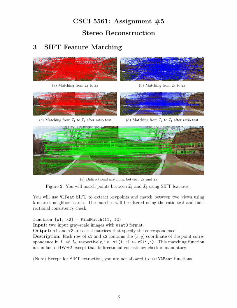
Figure 3: Given matches, you will compute a fundamental matrix to draw epipolarlines.
function [F] = ComputeF(x1, x2)
Input: x1 and x2 are n× 2 matrices that specify the correspondence.Output: F ∈ R3×3 is the fundamental matrix.Description: F is robustly computed by the 8-point algorithm within RANSAC. Notethat the rank of the fundamental matrix needs to be 2 (SVD clean-up should be ap-plied.). You can verify the validity of fundamental matrix by visualizing epipolar lineas shown in Figure 3.
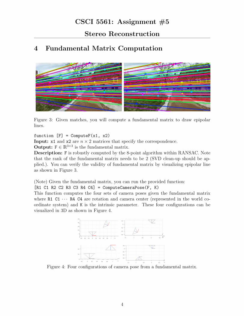
(Note) Given the fundamental matrix, you can run the provided function:[R1 C1 R2 C2 R3 C3 R4 C4] = ComputeCameraPose(F, K)
This function computes the four sets of camera poses given the fundamental matrixwhere R1 C1 · · · R4 C4 are rotation and camera center (represented in the world co-ordinate system) and K is the intrinsic parameter. These four configurations can bevisualized in 3D as shown in Figure 4.
-0.6 -0.4 -0.2 0 0.2 0.4 0.6 0.8 1 1.20
0.8
0.6
0.4
0.2
0
0.5
0.2
0
0
-0.2
-0.5
-0.4
-1
-0.6
-1.5 0.50-0.5
00
0.2
-0.2
0.4
0 0.2 0.4 0.6 0.8 10.50-0.5-1
0.2
0
-0.2
-0.4
-1.5
-0.6
0
Figure 4: Four configurations of camera pose from a fundamental matrix.
4
CSCI 5561: Assignment #5
Stereo Reconstruction
5 Triangulation
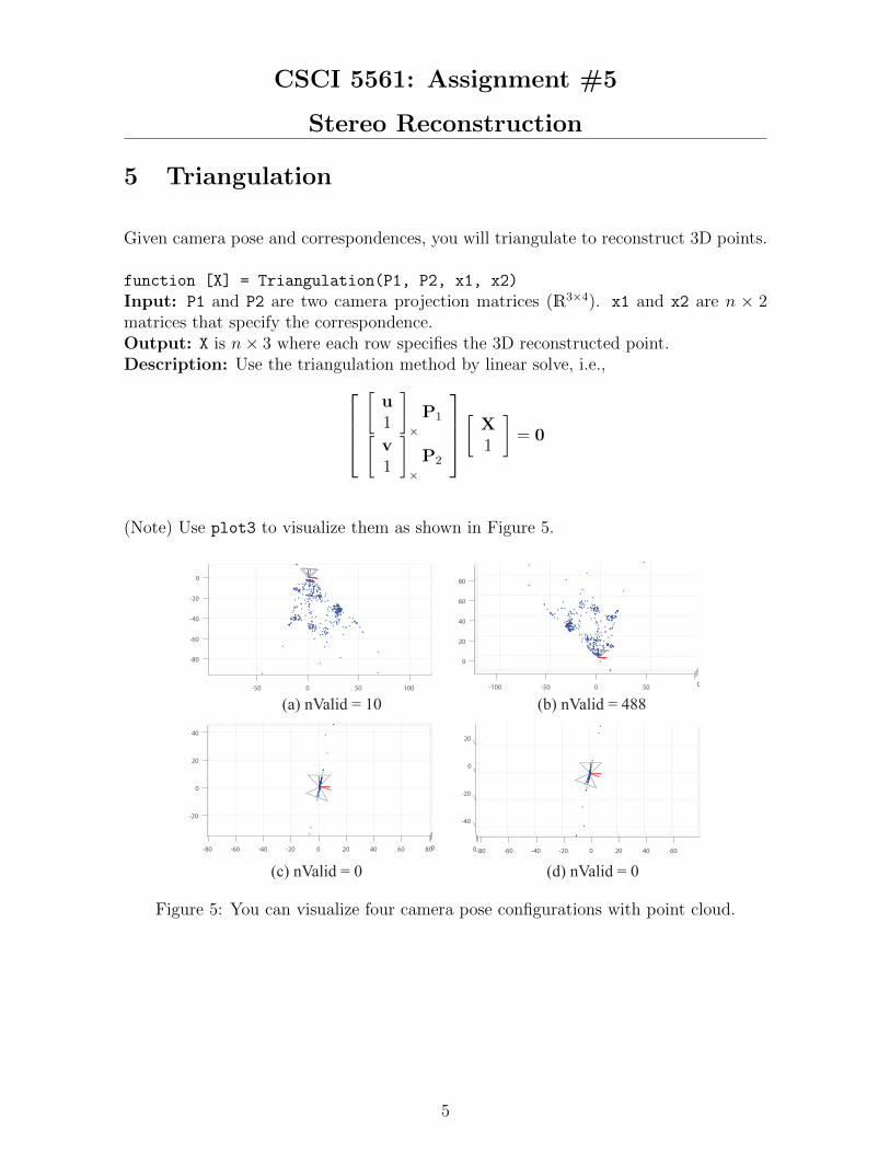
Given camera pose and correspondences, you will triangulate to reconstruct 3D points.
function [X] = Triangulation(P1, P2, x1, x2)
Input: P1 and P2 are two camera projection matrices (R3×4). x1 and x2 are n × 2matrices that specify the correspondence.Output: X is n× 3 where each row specifies the 3D reconstructed point.Description: Use the triangulation method by linear solve, i.e.,
[u1
]×P1[
v1
]×P2
[ X1
]= 0
(Note) Use plot3 to visualize them as shown in Figure 5.
100500
0
-20
-50
-40
-60
-80
0
0
-100
20
-50
40
60
0
80
50
40
20
806040
0
200-20
-20
-40-60-80 0
-40
-20
0
20
0 6040200-20-40-60-80
(a) nValid = 10 (b) nValid = 488
(c) nValid = 0 (d) nValid = 0
Figure 5: You can visualize four camera pose configurations with point cloud.
5
CSCI 5561: Assignment #5
Stereo Reconstruction
6 Pose Disambiguation
Given four configurations of relative camera pose and reconstructed points, you willfind the best camera pose by verifying through 3D point triangulation.
function [R,C,X] = DisambiguatePose(R1,C1,X1,R2,C2,X2,R3,C3,X3,R4,C4,X4)
Input: R1, C1, X1 · · · R4, C4, X4 are four sets of camera rotation, center, and 3D re-constructed points.Output: R, C, X are the best camera rotation, center, and 3D reconstructed points.Description: The 3D point must lie in front of the both cameras, which can be testedby:
rT3 (X−C) > 0 (1)
where r3 is the 3rd row of the rotation matrix. In Figure 5, nValid means the numberof points that are in front of both cameras. (b) configuration produces the maximumnumber of valid points, and therefore the best configuration is (b).
6
CSCI 5561: Assignment #5
Stereo Reconstruction
7 Stereo
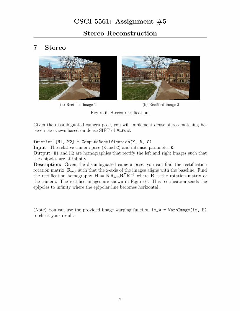
(a) Rectified image 1 (b) Rectified image 2
Figure 6: Stereo rectification.
Given the disambiguated camera pose, you will implement dense stereo matching be-tween two views based on dense SIFT of VLFeat.
function [H1, H2] = ComputeRectification(K, R, C)
Input: The relative camera pose (R and C) and intrinsic parameter K.Output: H1 and H2 are homographies that rectify the left and right images such thatthe epipoles are at infinity.Description: Given the disambiguated camera pose, you can find the rectificationrotation matrix, Rrect such that the x-axis of the images aligns with the baseline. Findthe rectification homography H = KRrectR
TK−1 where R is the rotation matrix ofthe camera. The rectified images are shown in Figure 6. This rectification sends theepipoles to infinity where the epipolar line becomes horizontal.
(Note) You can use the provided image warping function im_w = WarpImage(im, H)
to check your result.
7
CSCI 5561: Assignment #5
Stereo Reconstruction
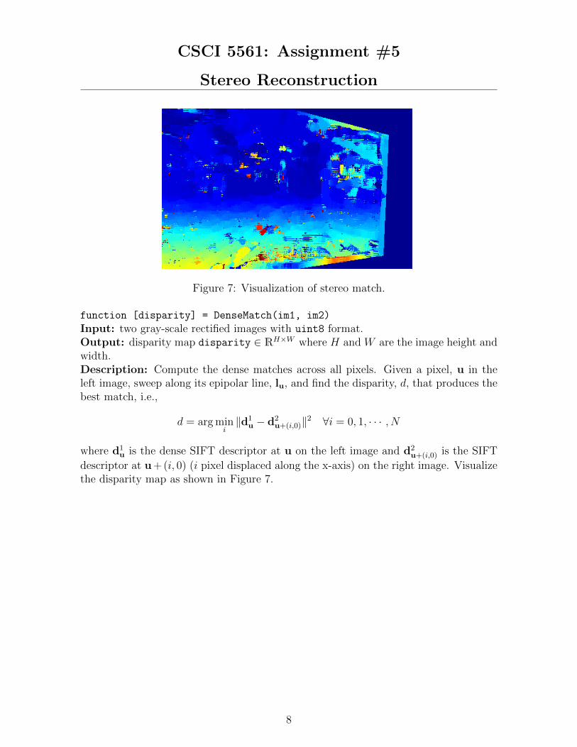
Figure 7: Visualization of stereo match.
function [disparity] = DenseMatch(im1, im2)
Input: two gray-scale rectified images with uint8 format.Output: disparity map disparity ∈ RH×W where H and W are the image height andwidth.Description: Compute the dense matches across all pixels. Given a pixel, u in theleft image, sweep along its epipolar line, lu, and find the disparity, d, that produces thebest match, i.e.,
d = arg mini‖d1
u − d2u+(i,0)‖2 ∀i = 0, 1, · · · , N
where d1u is the dense SIFT descriptor at u on the left image and d2
u+(i,0) is the SIFT
descriptor at u+ (i, 0) (i pixel displaced along the x-axis) on the right image. Visualizethe disparity map as shown in Figure 7.
8