mtl4561/5561 fire detector interface
TRANSCRIPT
1 SM4561_5561 rev 1
Safety manual
MTL intrinsic safety solutions February 2020
SM4561_5561 rev 1
MTL4561/5561 Fire detector interface
2-channel, for use with conventional Fire &
Smoke detectors located in hazardous areas
Eaton Electric Ltd, Luton is a certified Functional Safety Management company
meeting the requirements of IEC61508: 2010 Part 1, Clause 6.
* Subject to specific operating conditions. Refer to content of this manual for details.
2 SM4561_5561 rev 1
Fire & Smoke Detector Interface, 2-channel
Contents
1 INTRODUCTION ................................................................. 3
1.1 Application and function .................................... 3
1.2 Product build information covered
by this manual ............................................................ 3
2 SYSTEM CONSIDERATIONS ............................................... 4
2.1 Associated System Components ........................ 4
3 ASSESSMENT OF FUNCTIONAL SAFETY ............................ 5
3.1 Hardware Safety Integrity .................................. 5
3.2 Assumptions ....................................................... 5
3.3 Systematic Safety Integrity ................................. 5
3.4 SIL Capability ...................................................... 6
3.5 Example of use in a safety function .................... 6
3.6 EMC .................................................................... 6
3.7 Environmental .................................................... 7
4 INSTALLATION ................................................................... 7
5 MAINTENANCE .................................................................. 7
6 APPENDICES ...................................................................... 8
6.1 Appendix A: Summary of
applicable standards .................................................. 8
6.2 Appendix B: Proof Test Procedure,
MTL4561 and MTL5561 Modules .............................. 8
This manual supports the application of the product in functional-safety related loops. It must be used in conjunction
with other supporting documents to achieve correct installation, commissioning and operation. Specifically, the
product data sheet, instruction manual and applicable certificates for the product should be consulted, all of which
are available on the MTL web site.
In the interest of further technical developments, Eaton reserve the right to make design changes
Hardware Fault Tolerance
(HFT) †
Module type:
MTL4561
MTL5561
0, 1
† These modules have an inherent fault tolerance of 0.
Functional Safety
Approved Company
3 SM4561_5561 rev 1
1 INTRODUCTION
1.1 Application and function
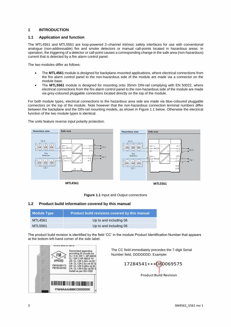
The MTL4561 and MTL5561 are loop-powered 2–channel intrinsic safety interfaces for use with conventional analogue (non-addressable) fire and smoke detectors or manual call-points located in hazardous areas. In operation, the triggering of a detector or call-point causes a corresponding change in the safe area (non-hazardous) current that is detected by a fire alarm control panel. The two modules differ as follows:
• The MTL4561 module is designed for backplane-mounted applications, where electrical connections from the fire alarm control panel to the non-hazardous side of the module are made via a connector on the module base.
• The MTL5561 module is designed for mounting onto 35mm DIN-rail complying with EN 50022, where electrical connections from the fire alarm control panel to the non-hazardous side of the module are made via grey-coloured pluggable connectors located directly on the top of the module.
For both module types, electrical connections to the hazardous area side are made via blue-coloured pluggable connectors on the top of the module. Note however that the non-hazardous connection terminal numbers differ between the backplane and the DIN-rail mounting models, as shown in Figure 1.1 below. Otherwise the electrical function of the two module types is identical. The units feature reverse input polarity protection.
Figure 1.1 Input and Output connections
1.2 Product build information covered by this manual
Module Type Product build revisions covered by this manual
MTL4561 Up to and including 06
MTL5561 Up to and including 06
The product build revision is identified by the field ‘CC’ in the module Product Identification Number that appears at the bottom left-hand corner of the side label:
The CC field immediately precedes the 7-digit Serial
Number field, DDDDDDD. Example:
MTL4561 MTL5561
4 SM4561_5561 rev 1
2 SYSTEM CONSIDERATIONS
2.1 Associated System Components
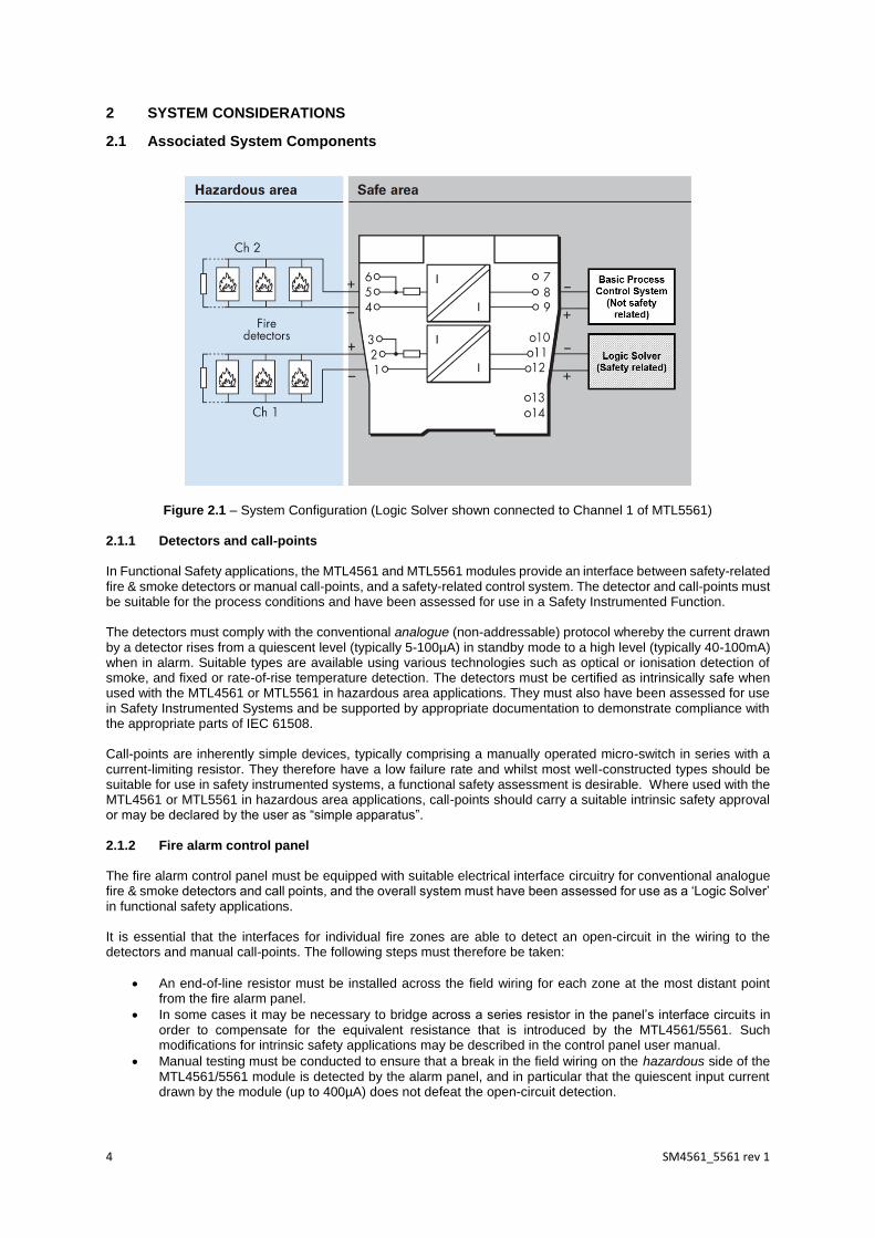
Figure 2.1 – System Configuration (Logic Solver shown connected to Channel 1 of MTL5561) 2.1.1 Detectors and call-points In Functional Safety applications, the MTL4561 and MTL5561 modules provide an interface between safety-related fire & smoke detectors or manual call-points, and a safety-related control system. The detector and call-points must be suitable for the process conditions and have been assessed for use in a Safety Instrumented Function. The detectors must comply with the conventional analogue (non-addressable) protocol whereby the current drawn by a detector rises from a quiescent level (typically 5-100µA) in standby mode to a high level (typically 40-100mA) when in alarm. Suitable types are available using various technologies such as optical or ionisation detection of smoke, and fixed or rate-of-rise temperature detection. The detectors must be certified as intrinsically safe when used with the MTL4561 or MTL5561 in hazardous area applications. They must also have been assessed for use in Safety Instrumented Systems and be supported by appropriate documentation to demonstrate compliance with the appropriate parts of IEC 61508. Call-points are inherently simple devices, typically comprising a manually operated micro-switch in series with a current-limiting resistor. They therefore have a low failure rate and whilst most well-constructed types should be suitable for use in safety instrumented systems, a functional safety assessment is desirable. Where used with the MTL4561 or MTL5561 in hazardous area applications, call-points should carry a suitable intrinsic safety approval or may be declared by the user as “simple apparatus”. 2.1.2 Fire alarm control panel The fire alarm control panel must be equipped with suitable electrical interface circuitry for conventional analogue fire & smoke detectors and call points, and the overall system must have been assessed for use as a ‘Logic Solver’ in functional safety applications. It is essential that the interfaces for individual fire zones are able to detect an open-circuit in the wiring to the detectors and manual call-points. The following steps must therefore be taken:
• An end-of-line resistor must be installed across the field wiring for each zone at the most distant point from the fire alarm panel.
• In some cases it may be necessary to bridge across a series resistor in the panel’s interface circuits in order to compensate for the equivalent resistance that is introduced by the MTL4561/5561. Such modifications for intrinsic safety applications may be described in the control panel user manual.
• Manual testing must be conducted to ensure that a break in the field wiring on the hazardous side of the MTL4561/5561 module is detected by the alarm panel, and in particular that the quiescent input current drawn by the module (up to 400µA) does not defeat the open-circuit detection.
5 SM4561_5561 rev 1
In order to avoid nuisance trips, the fire alarm control panel shall also be capable of distinguishing the difference between a detector or call-point in alarm condition from a short-circuit across the field wiring. Again, it may be necessary to confirm this by testing, since the insertion loss of the MTL4561/5561 may alter the current levels that flow in the different states.
3 ASSESSMENT OF FUNCTIONAL SAFETY
3.1 Hardware Safety Integrity
The hardware assessment shows that MTL4561 and MTL5561 modules:
• have a hardware fault tolerance (HFT) of 0 • are classified as a Type A device (“non-complex” component with well-defined failure modes) • have no internal diagnostic elements
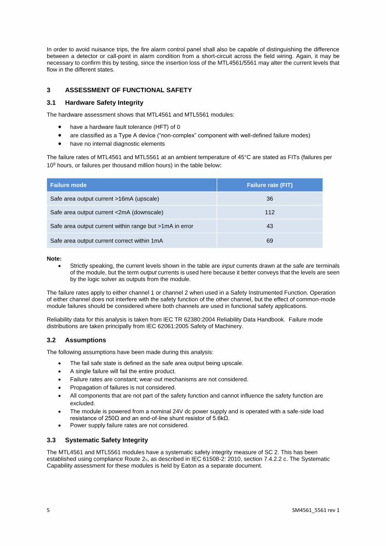
The failure rates of MTL4561 and MTL5561 at an ambient temperature of 45°C are stated as FITs (failures per
109 hours, or failures per thousand million hours) in the table below:
Failure mode Failure rate (FIT)
Safe area output current >16mA (upscale) 36
Safe area output current <2mA (downscale) 112
Safe area output current within range but >1mA in error 43
Safe area output current correct within 1mA 69
Note:
• Strictly speaking, the current levels shown in the table are input currents drawn at the safe are terminals of the module, but the term output currents is used here because it better conveys that the levels are seen by the logic solver as outputs from the module.
The failure rates apply to either channel 1 or channel 2 when used in a Safety Instrumented Function. Operation of either channel does not interfere with the safety function of the other channel, but the effect of common-mode module failures should be considered where both channels are used in functional safety applications. Reliability data for this analysis is taken from IEC TR 62380:2004 Reliability Data Handbook. Failure mode distributions are taken principally from IEC 62061:2005 Safety of Machinery.
3.2 Assumptions
The following assumptions have been made during this analysis:
• The fail safe state is defined as the safe area output being upscale.
• A single failure will fail the entire product.
• Failure rates are constant; wear-out mechanisms are not considered.
• Propagation of failures is not considered.
• All components that are not part of the safety function and cannot influence the safety function are
excluded.
• The module is powered from a nominal 24V dc power supply and is operated with a safe-side load resistance of 250Ω and an end-of-line shunt resistor of 5.6kΩ.
• Power supply failure rates are not considered.
3.3 Systematic Safety Integrity
The MTL4561 and MTL5561 modules have a systematic safety integrity measure of SC 2. This has been established using compliance Route 2S, as described in IEC 61508-2: 2010, section 7.4.2.2 c. The Systematic Capability assessment for these modules is held by Eaton as a separate document.

6 SM4561_5561 rev 1
3.4 SIL Capability
Considering both the hardware safety integrity and the systematic capability, this allows the module to be used in safety functions up to SIL 2 in a simplex architecture (HFT=0). The hardware safety integrity assessment has been conducted according to compliance Route 1H, as described in IEC 61508-2: 2010, section 7.4.4. Note:
• Independent of hardware architecture and systematic capability considerations, the hardware probability of failure for the entire safety function needs to be calculated for the application to ensure the required PFH (for a high or continuous demand safety function) or PFDAVG (for a low demand safety function) for the SIL is met.
SFF 3.5 Example of use in a safety function
In this example, the application context is assumed to be:
• The element safety function is to repeat current within ±1mA. • The logic solver will diagnose currents below 2mA as faults and take appropriate action. • The logic solver will diagnose currents above the short-circuit detection threshold and take appropriate
action.
The failure modes shown above can then be defined as:
Failure mode Category
Safe area output current >16mA (upscale) λdd
Safe area output current <2mA (downscale) λdd
Safe area output current within range but >1mA in error λdu
Safe area output current correct within 1mA λne
The failure rates of the MTL4561 and MTL5561 for these categories are then (FITs):
Model λsd λsu λdd λdu λne
MTL4561 or MTL5561 (either channel) 0 0 148 43 69
In this example, the Safe Failure Fraction (SFF) is 77.5%.
The SFF is calculated as (λdd + λsd + λsu)/(λdu + λdd + λsd + λsu), and stated as a percentage. Note that “No-effect”
failures (λne ) are not used in the calculation of SFF. No-effect failures are defined in IEC 61508-4: 2010 as failures
of elements (or components) that are part of the safety function but have no effect on the safety function.
Where the calculated SFF is between 60 and 90%, the requirements for SIL 2 are met according to Table 2 of IEC 61508-2: 2010, for a hardware fault tolerance of 0. Note:
• The failure mode “Safe area output current >16mA” is indicated here as a dangerous, detected failure
(λdd). Failures of this type will result in either a nuisance alarm trip or triggering of the short-circuit
detection, depending on the fault current level. It can be argued that nuisance trips are safe, detected
(λsd), but this would not change the numerical value of SFF.
3.6 EMC
The MTL4561 and MTL5561 modules are designed for operation in normal industrial electromagnetic environment but, to support good practice, modules should be mounted without being subjected to undue conducted or radiated interference. See Appendix A for applicable standards and levels.
7 SM4561_5561 rev 1
3.7 Environmental
The MTL4561 and MTL5561 modules are designed for operation over the temperature range from -20°C to +60°C, and at up to 95% non-condensing relative humidity. The modules are intended to be mounted in a normal industrial environment without excessive vibration, as specified for the MTL4500 and MTL5500 product ranges. See Appendix A for applicable standards and levels. Continued reliable operation will be assured if the exposure to temperature and vibration are within the values given in the specification.
4 INSTALLATION
There are two aspects of safety that must be considered when installing the MTL4561 and MTL5561 modules. These are:
• Functional safety • Intrinsic safety
To comply with intrinsic safety requirements, reference should be made to the relevant sections in the instruction manual INM4500/4600 (for MTL4561) or INM5500 (for MTL5561), which are available to download from the Eaton-MTL website. In many countries there are also specific codes of practice and industry guidelines, which must also be adhered to. Provided that these installation requirements are followed then there are no additional environmental factors to meet the needs of applying the products for functional safety use. To guard against the effects of dust and water the modules should be mounted in an enclosure providing at least IP54 protection degree, or the mounting location should provide equivalent protection such as inside an equipment cabinet.
5 MAINTENANCE
To follow the guidelines relating to operation and maintenance of intrinsically safe equipment in a hazardous area, yearly periodic audits of the installation are required by the various codes of practice. In addition, proof-testing of the loop operation to conform with functional safety requirements should be carried out at the intervals determined by safety case assessment. Proof testing must be carried out according to the application requirements, but it is recommended that this be performed at least once every three years. Refer to Appendix B for the proof testing procedure for the MTL4561/MTL5561 modules. Note that there may also be specific requirements laid down in the E/E/PE operational maintenance procedure for the complete installation. If an MTL4561 or MTL5561 module is found to be faulty during commissioning or during the normal lifetime of the product, then such failures should be reported to the local Eaton-MTL office. Where appropriate, a Customer Incident Report (CIR) will be notified by Eaton to enable the module to be returned to the factory for analysis. If the module is within the warranty period and the failure is due to defective components or manufacture, then a replacement will be sent. Consideration should be given to the service lifetime for a device of this type, which is in the region of ten years. Operating an MTL4561 or MTL5561 module for longer than this period could invalidate the functional safety analysis, meaning that the overall safety function no longer meets its target SIL. If high failure rates of a module are detected in service, indicating that it has entered the ‘end of life phase’ of its service life, then it should be replaced promptly.
8 SM4561_5561 rev 1
6 APPENDICES
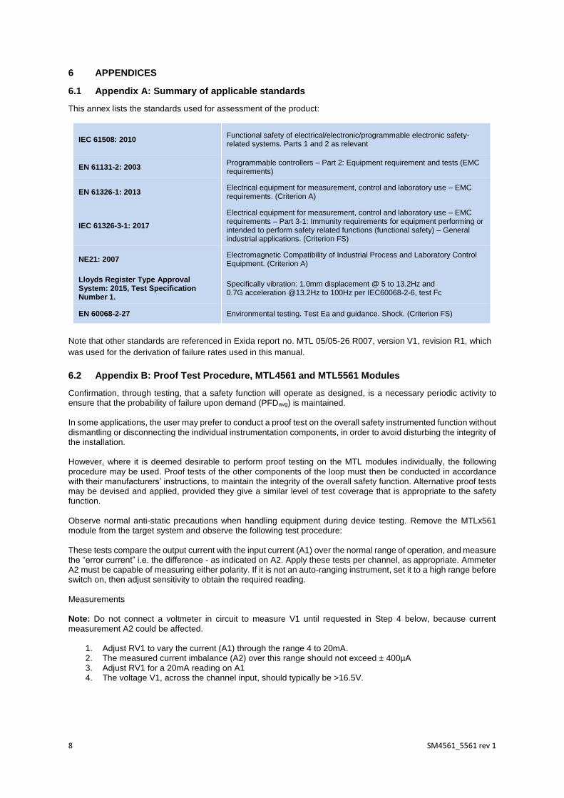
6.1 Appendix A: Summary of applicable standards
This annex lists the standards used for assessment of the product:
IEC 61508: 2010 Functional safety of electrical/electronic/programmable electronic safety-related systems. Parts 1 and 2 as relevant
EN 61131-2: 2003 Programmable controllers – Part 2: Equipment requirement and tests (EMC requirements)
EN 61326-1: 2013 Electrical equipment for measurement, control and laboratory use – EMC requirements. (Criterion A)
IEC 61326-3-1: 2017
Electrical equipment for measurement, control and laboratory use – EMC requirements – Part 3-1: Immunity requirements for equipment performing or intended to perform safety related functions (functional safety) – General industrial applications. (Criterion FS)
NE21: 2007 Electromagnetic Compatibility of Industrial Process and Laboratory Control Equipment. (Criterion A)
Lloyds Register Type Approval System: 2015, Test Specification Number 1.
Specifically vibration: 1.0mm displacement @ 5 to 13.2Hz and 0.7G acceleration @13.2Hz to 100Hz per IEC60068-2-6, test Fc
EN 60068-2-27 Environmental testing. Test Ea and guidance. Shock. (Criterion FS)
Note that other standards are referenced in Exida report no. MTL 05/05-26 R007, version V1, revision R1, which
was used for the derivation of failure rates used in this manual.
6.2 Appendix B: Proof Test Procedure, MTL4561 and MTL5561 Modules
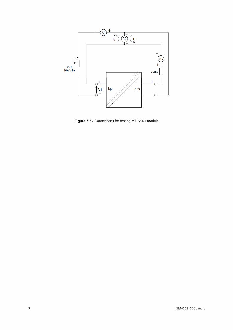
Confirmation, through testing, that a safety function will operate as designed, is a necessary periodic activity to ensure that the probability of failure upon demand (PFDavg) is maintained. In some applications, the user may prefer to conduct a proof test on the overall safety instrumented function without dismantling or disconnecting the individual instrumentation components, in order to avoid disturbing the integrity of the installation. However, where it is deemed desirable to perform proof testing on the MTL modules individually, the following procedure may be used. Proof tests of the other components of the loop must then be conducted in accordance with their manufacturers’ instructions, to maintain the integrity of the overall safety function. Alternative proof tests may be devised and applied, provided they give a similar level of test coverage that is appropriate to the safety function. Observe normal anti-static precautions when handling equipment during device testing. Remove the MTLx561 module from the target system and observe the following test procedure: These tests compare the output current with the input current (A1) over the normal range of operation, and measure the “error current” i.e. the difference - as indicated on A2. Apply these tests per channel, as appropriate. Ammeter A2 must be capable of measuring either polarity. If it is not an auto-ranging instrument, set it to a high range before switch on, then adjust sensitivity to obtain the required reading. Measurements Note: Do not connect a voltmeter in circuit to measure V1 until requested in Step 4 below, because current measurement A2 could be affected.
1. Adjust RV1 to vary the current (A1) through the range 4 to 20mA. 2. The measured current imbalance (A2) over this range should not exceed ± 400µA 3. Adjust RV1 for a 20mA reading on A1 4. The voltage V1, across the channel input, should typically be >16.5V.
9 SM4561_5561 rev 1
Figure 7.2 - Connections for testing MTLx561 module

10 SM4561_5561 rev 1
THIS PAGE IS LEFT INTENTIONALLY BLANK

11 SM4561_5561 rev 1
THIS PAGE IS LEFT INTENTIONALLY BLANK

12 SM4561_5561 rev 1
THIS PAGE IS LEFT INTENTIONALLY BLANK
13 SM4561_5561 rev 1
Global Locations: AUSTRALIA Eaton Electrical (Australia) Pty Ltd,
10 Kent Road, Mascot, New South Wales, 2020, Australia
Tel: +61 1300 308 374 Fax: +61 1300 308 463
E-mail [email protected]
CHINA Cooper Electric (Shanghai) Co. Ltd
955 Shengli Road, Heqing Industrial Park
Pudong New Area, Shanghai 201201
Tel: +86 21 2899 3817 Fax: +86 21 2899 3992
E-mail: [email protected]
FRANCE MTL Instruments sarl, Les Carrés du Parc
7 rue des Rosiéristes, 69410 Champagne au Mont d’Or
Tel: +33 (0)4 37 46 16 53 Fax: +33 (0)4 37 46 17 20
E-mail: [email protected]
GERMANY MTL Instruments GmbH,
Heinrich-Hertz-Str. 12, 50170 Kerpen, Germany
Tel: +49 (0)22 73 98 12 - 0 Fax: +49 (0)22 73 98 12 - 2 00
E-mail: [email protected]
INDIA MTL India, No 35 Nehru Street
Off Old Mahabalipuram Road
Sholinganallur Chennai - 600 119
Tel: +91 (0) 44 2450 1660 / 1857 Fax: +91 (0) 44 2450 1463
E-mail: [email protected]
BENELUX MTL Instruments BV,
Ambacht 6, 5301 KW Zaltbommel
The Netherlands
Tel: +31 (0)418 570290 Fax: +31 (0)418 541044
E-mail: [email protected]
ITALY MTL Italia srl,
Via San Bovio, 3, 20090 Segrate, Milano, Italy
Tel: +39 02 959501 Fax: +39 02 95950759
E-mail: [email protected]
SINGAPORE Eaton Electric (Singapore) Pte Ltd
100G Pasir Panjang Road
Interlocal Centre
#07-08 Singapore 118523
#02-09 to #02-12 (Warehouse and Workshop)
Tel: +65 6 645 9888 ext 9864/9865
Fax: +65 6 645 9811
E-mail: [email protected]
UNITED KINGDOM Eaton Electric Ltd, Great Marlings,
Butterfield, Luton
Bedfordshire LU2 8DL
Tel: +44(0)1582 723633 Fax:+44(0)1582 422283
Email: [email protected]
AMERICAS Cooper Crouse-Hinds MTL Inc.
3413 N. Sam Houston Parkway W.
Suite 200, Houston TX 77086, USA
Tel: +1 281-571-8065 Fax: +1 281-571-8069
E-mail: [email protected]
SOUTH KOREA Cooper Crouse-Hinds Korea
7F. Parkland Building 237-11 Nonhyun-dong Gangnam-gu,
Seoul 135-546, South Korea.
Tel: +82 6380 4805 Fax: +82 6380 4839
E-mail: [email protected]
UNITED ARAB EMIRATES Cooper Industries/Eaton Corporation
Office 205/206, 2nd Floor SJ Towers, off. Old Airport Road, Abu
Dhabi,
United Arab Emirates
Tel: +971 2 44 66 840 Fax: +971 2 44 66 841
E-mail: [email protected]
Eaton Electric Limited, Great Marlings, Butterfield, Luton Beds, LU2 8DL, UK. Tel: + 44 (0)1582 723633 Fax: + 44 (0)1582 422283 E-mail: [email protected] www.mtl-inst.com © 2020 Eaton All Rights Reserved Publication No. SM4561_5561 rev 1 040220 Feb 2020
The given data is only intended as a product description and should not be regarded as a legal warranty of properties or guarantee. In the interest of further technical developments, we reserve the right to make design changes.
Connect with Eaton, MTL: