csp2 comments - northmet sdeis - final
TRANSCRIPT

CENTER for SCIENCE in PUBLIC PARTICIPATION 224 North Church Avenue, Bozeman, MT 59715
Phone (406) 585-9854 / Fax (406) 585-2260 / web: www.csp2.org / e-mail: [email protected]
“Technical Support for Grassroots Public Interest Groups”
CSP2
March 14, 2014
Lisa Fay EIS Project Manager MDNR Division of Ecological and Water Resources Environmental Review Unit 500 Lafayette Road, Box 25 St. Paul, MN 55155-4025 [email protected] RE: Comments on NorthMet Mining Project and Land Exchange Supplemental Draft
Environmental Impact Statement, prepared by Minnesota Department of Natural Resources, United States Army Corps of Engineers, United States Forest Service, November, 2013
The Center for Science in Public Participation provides technical advice to public interest groups, non-governmental organizations, regulatory agencies, mining companies, and indigenous communities on the environmental impacts of mining. CSP2 specializes in hard rock mining, especially with those issues related to water quality impacts and reclamation bonding.
Dr. David Chambers has 37 years of experience in mineral exploration and development – 15 years of technical and management experience in the mineral exploration industry, and for the past 22 years he has served as an advisor on the environmental effects of mining projects both nationally and internationally. He has Professional Engineering Degree in Physics from the Colorado School of Mines, a Master of Science Degree in Engineering from the University of California at Berkeley, a Ph.D. in Environmental Planning from Berkeley, and is a registered professional geophysicist in California (# GP 972).
Stuart M. Levit has a Masters Degree in Land Rehabilitation from Montana State University in 1989, where he focused on natural resources issues, mining, and environmental regulation, and a law degree from the University of Montana in 1994. He worked for the Montana Abandoned Mines Reclamation Bureau where he designed reclamation projects, and was oversaw site evaluation, engineering, and construction of these projects. Stu has worked with the Center for Science in Public Participation since 2000, concentrating on reclamation planning and bonding, the adequacy of environmental impact statements, and water pollution regulatory issues.
SUMMARY
The NorthMet Project Supplemental Draft EIS is based on a plethora of information, but there are still several important areas that need additional work and/or revisions:
(1) Probably the most glaring omission is that there is only the most scant analysis of the financial surety that will be needed for this project. As is discussed in more detail to follow, the financial surety for this project could be in excess of $400 million. This is very significant potential impact not only to the financial requirements of the mine owners, but also to the citizens of Minnesota, who are ultimately accountable should the mine operator go bankrupt without an adequate financial surety to

Page 2 of 32
close the mine and treat waste water. If the mine operator were to go bankrupt without an adequate financial surety public funds for closure would either need to be provided, or the public would bear the environmental consequences of not properly closing the mine. Either way, the public would pay, probably for centuries.
(2) Every Draft EIS should contain a Draft Reclamation Plan which includes a detailed analysis of the financial surety, so that it is demonstrated before the project is allowed to proceed that project closure can be accomplished using demonstrated reclamation techniques, and at a cost that is affordable. Lack of a viable reclamation plan and closure cost estimate is a major flaw in the SDEIS.
Many sections of the Reclamation Plan (and its referenced documents, such as the Mine Plan, Water Management Plan, Wetlands Management Plan are more accurately plans to plan reclamation than actual reclamation plans. As described in these comments, the Reclamation Plan often lack detail and specific goals and methods necessary to evaluate the likely success of reclamation and provide comment about how to improve the chances of success.
These are the most critical issues, but there are a number of other important points to be made in the Section-Specific Comments below.
SECTION-SPECIFIC COMMENTS:
2.6 Financial Assurance
This section, which should be one of the major points of analysis and public disclosure, is a mere ½ page in length. It is stated:
“The level of engineering design and planning required to calculate detailed financial assurance amounts is typically made available during the permitting process.” (SDEIS, p 2-10)
This statement is most probably not correct. The engineering design and planning to calculate detailed financial assurance is available at the point a project reaches the Draft EIS stage. For a company to reach this stage without having this information available, and without having performed this calculation internally, would be fiscally irresponsible to the company’s shareholders and board of directors. Management could not go forward with a proposal to the company board to spend the hundreds of millions/billions of dollars involved in constructing a mine of this type without knowing what the likely closure costs will be, since those costs are also likely in the hundreds of millions of dollars range.
Likewise, the public is the final resting point for any financial surety. If there is a bankruptcy or other applicable failure to perform that requires the use of the financial surety, and this surety is lacking the public either makes up the deficit with tax dollars, or bears the environmental costs of not performing the reclamation, water treatment, or any other costs related to the deficit in the financial surety. With this much money at stake, regulatory agencies should want the most thorough review possible before allowing a project to go forward.
Recommendation: A detailed financial surety calculation, based on the project as proposed by the applicant, should be presented in the SDEIS.

Page 3 of 32
3.1.1 NorthMet Project Proposed Action Overview
3.1.1.7 Project Closure Overview
A very important component of the financial assurance, long term water treatment, is mentioned in this section:
“Mechanical water treatment is part of the modeled NorthMet Project Proposed Action for the duration of the simulations (200 years at the Mine Site and 500 years at the Plant Site). The duration of the simulations was determined based on capturing the highest predicted concentrations of the modeled NorthMet Project Proposed Action. It is uncertain how long the NorthMet Project Proposed Action would require water treatment, but it is expected to be long term; actual treatment requirements would be based on measured, rather than modeled, NorthMet Project water quality performance, as determined through monitoring requirements.” (SDEIS, p 3-5, emphasis added)
It is appropriate to base models like this on worst-case predictions, because there are too many examples of situations where conditions turned out to be worse than the worst-case prediction. It is also appropriate to eventually base water quality predictions and the need for water quality treatment on actual conditions, once a mine is in operation. However, for a new mine the initial calculations of a financial surety must be based the best information available, because the mine could go bankrupt before a sufficient amount of data has been collected to establish an operational baseline. An initial calculation of a financial surety must necessarily be based on worst-case water quality predictions – until operational data can prove conditions to the contrary.
In effect, from a worst case standpoint any prediction of poor water quality from a model that extends more than 5 years beyond the closure of a mine must essentially be treated as requiring water treatment in perpetuity. (For example, it might take 5 years for tailings pond seepage to stabilize post-closure.) This is because no geochemical model today is accurate enough to predict how much time it will take for water quality to improve enough to terminate water treatment required after mine closure.
Recommendation: The initial calculation of the financial surety should be based on worst-case water quality predictions, and on the project as proposed by the applicant.
3.2.2.1.6 Haulage, Storage, and Transport of Ore
Ore will be transported from the mine to the mill in side-dump rail cars. (see Figure 3.2-21: Side Dump Railroad Cars, SDEIS, p 3-85): at the Rail Transfer Hopper haul trucks dump run-of-mine ore into the hopper, where it is loaded by conveyor onto the rail cars. Each 100-ton rail car can be loaded in one minute (SDEIS, p 3-43). There is no mention of an enclosed building, so it is assumed that this is being done in the open. Since this is run-of-mine ore there will be a fraction of the ore that is dust-sized material. The high transfer rate both with the haul trucks dumping to the hopper, and the conveyor loading the rail cars, will generate a significant amount of dust in the vicinity, and in the predominant downwind direction of the Rail Transfer Hopper. And, since the rail cars are open-top, there will be an accumulation of dust along the rail corridor between the mine and mill.
Ore-dust contains a number of potential contaminants which, even though a low concentrations, could accumulate over years of use.
Recommendation: The Rail Transfer Hopper and rail car loading conveyor and platform should be in an enclosed structure, and the rail cars fitted with a top that would limit the loss of ore-dust along the rail line between the mine and mill.
Page 4 of 32
3.2.2.1.8 Engineered Water Controls
Category 1 Stockpile Water Containment System and Cover
Waste Rock Liner and Cover Systems
A cutoff wall would be constructed to enclose the Category 1 waste rock pile to prevent metals leaching contaminants from reaching groundwater.
“The cutoff wall would be constructed by excavating a trench down to bedrock and backfilling it with a compacted soil material or by placing a manufactured geosynthetic clay barrier in the trench. Compacted soil material would have a hydraulic conductivity specification of no more than 1x10⁻⁵ centimeters per second (cm/sec).” (SDEIS, p 3-46, emphasis added)
At a permeability 1x10⁻⁵ cm/sec, a fluid will move thorough this material at a rate of slightly more than 10 feet/year. For a 3 foot wide cutoff wall that means 3+ pore volumes would pass through the wall each year.
If the permeability is lowered to 1x10⁻⁶ cm/sec, a fluid will move through the wall at a rate of 1 foot/year. For a 3 foot wide cutoff wall this means that it would take one pore volume 3 years to pass through the wall.
Recommendation: A permeability of 1x10⁻⁶ or less should be the goal of the cutoff walls for the Category 1 waste rock and the tailings cutoff wall.
Geosynthetic clay barriers can significantly increase the effectiveness of a cutoff wall, but it is not clear exactly what would trigger the use of this barrier. And, if installed, the barrier is likely to decrease the permeability of the section of the cutoff wall significantly over sections that do not have the barrier. It would be more consistent to use a barrier for the entire wall, or not at all.
Recommendation: More definition needs to be provided in when a geosynthetic clay barrier would be employed.
Category 2/3 and 4 Stockpiles and Ore Surge Pile Liners
In Table 3.2-9 Summary of the Stockpile Liners and Covers (SDEIS, p 3-51) the liners that will be employed for the 3 categories of waste rock and the ore surge pile are described. The Category 2/3 Stockpile liner: "12-inch compacted (1x10⁻⁵ cm/s) subgrade overlaid by 80-mil LLDPE geomembrane, covered by a 24-inch overliner drainage layer." The other liners have (1x10⁻⁶ cm/s) subgrades. Even though the effective permeability of the total liner system is governed by the permeability of the 80-mil LLDPE geomembrane, since 1x10⁻⁶ cm/s is essentially the minimum standard for a liner, for sake of standardization the Category 2/3 Stockpile liner should also have a 1x10⁻⁶ cm/s subgrade.
Recommendation: For standardization, both on the project and with most other liners, all liners made of natural materials should have a permeability of 1x10⁻⁶ or lower.
3.2.2.3.9 Transport of Consumables and Products
“Nickel and cobalt hydroxide and precious metal precipitate products would be shipped in sealed bulk bags or sealed containers. Copper and nickel concentrates would be shipped in solid-bottom rail cars with weather-tight covers. Cars would be checked before loading and any debris would be removed and holes plugged. Loading operations would be conducted in a building via a conveyor system. Car exteriors would be inspected before leaving the buildings and any concentrate on the car exterior would be recovered and returned to storage. The concentrate is expected to be 8 percent to

Page 5 of 32
10 percent moisture, which is not expected to generate dust during loading.” (SDEIS, p 3-116, emphasis added)
This is all good except for the last phrase (emphasized above). Inevitably there will, at the very least, be differences in the moisture content of the concentrate due to the amount of time it has been stored, or other factors. Concentrate ALWAYS creates dust at some point. If the rail cars are loaded in an enclosed building, this should limit the escape of dust to the environment, but to assume that dust will not occur, or that there will no leakage of small amounts of concentrate along the transportation corridor, would be an oversight.
In a related comment from Table 8-1 Major Differences of Opinion:
“GLIFWC disagrees that the amount of ore that could escape from rail cars would be small because the rail cars proposed for use are not sealed. GLIFWC states that, given the design and current condition of rail cars proposed for transport, an ecologically significant amount of spillage could occur into streams, wetlands, and their watersheds. GLIFWC believes that fugitive dust escaping through gaps in the rail cars is also a concern. GLIFWC does not believe that the method described to segregate fines in the center of the rail car, away from the gaps, is realistic. Further, GLIFWC does not believe that monitoring of the creeks along the rail line will be effective in preventing or minimizing impacts because once detected in monitoring, the impact will have already occurred. GLIFWC states that cleanup of ore dust in an aquatic environment is a long and difficult process.” (SDEIS, p 8-18)
This mirrors a CSP2 comment on the SDEIS, and we echo that comment, and support the GLIFWC comment above.
3.2.2.4 Financial Assurance
3.2.2.4.1 Cost Coverage and Estimation
The financial burden associated with closing the mine is largely incurred in the first few years of the mine’s life. When a mine is developed much of the disturbance takes place in the first few years of operation. As the mine operates the pit will get deeper, and waste piles larger, but the plant area, infrastructure, and tailings impoundment will stay largely the same.
Mine closure and post-closure costs represent a significant potential impact to the public that should be discussed as a part of the process. This cost estimate would be used to establish the amount of the post-closure financial surety, until it is amended by subsequent estimates that are based on actual operating costs and pre-closure reclamation experience at the site. However, it is stated:
"The level of engineering design and planning required to calculate detailed financial assurance amounts is typically made available during the permitting process and was not available at the time that this SDEIS was prepared." (SDEIS, p 3-136)
It would be equally correct to say ‘The level of engineering design and planning required to calculate detailed financial assurance amounts is typically available during the EIS process.’ The basic reason is that the operator must understand what the costs of reclamation and closure will be (and how that will influence the economics of the mining operation). Since the amount of money involved in reclamation and closure can be tens to hundreds of millions of dollars, management that does not forecast these expenditures for its own internal cost analysis would not be proposing a project that is fiscally defensible to its board of directors.

Page 6 of 32
An example of a reclamation plan with an appropriate level of planning detail and cost estimates is the Pogo Project Reclamation and Closure Plan, December 2002. The document is available digitally through the Alaska Department of Natural Resources, Anchorage, AK, and was is titled the Final Environmental Impact Statement, Pogo Gold Mine Project, USEPA, Region 10, September, 2003.
A “preliminary” reclamation closure cost estimate is presented in SDEIS Table 3.2-15 Preliminary Cost Estimate for Closure (SDEIS, p 3-138). However, this "preliminary closure cost estimate" is not supported by calculations and/or detailed information. One of the support documents "Proposed SDEIS Financial Assurance Language" (Foth, 2013) does discuss mine closure, but again does not provide sufficient documentation to substantiate this closure cost estimate. Foth, 2013, does contain the table identical to SDEIS Table 3.2-15.
Foth, 2013, also contains this explanation:
“In addition to the costs of the closure reclamation plan, PolyMet will also incur ongoing annual monitoring costs after water management as the project site reaches steady state. Depending on the year of closure, those costs are estimated to range from $3,500,000 to $6,000,000. Once again, these estimated costs include a 10% contingency factor.” (Foth, 2013, p 7, emphasis added)
From Table 1, above, the maximum liability for reclamation only would be incurred in Year 11 - $200 million.
And, according to the wording of the paragraph cited above, there is additional long-term care that would amount to $3.5 - $6.0 million/year. The long-term care cost is assumed to be operating and maintenance costs (lacking further explanation).
In order to develop a ballpark estimate of the financial surety that might be required for the NorthMet project, CSP2 developed a Net Present Value (NPV) spreadsheet to estimate the NPV of the long-term costs.
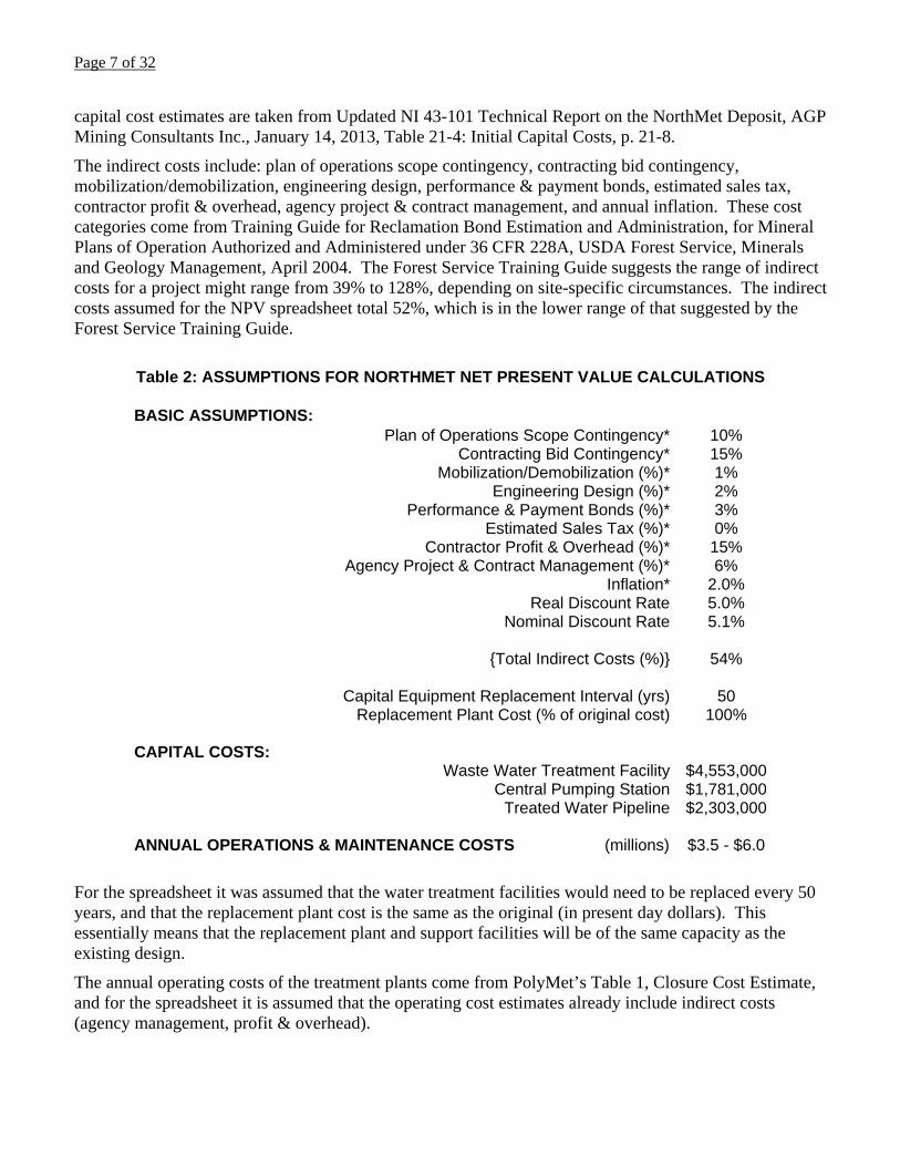
Table 2: Assumptions for NorthMet Net Present Value Calculations, contains a list of the basic assumptions made for this model. These assumptions include the direct costs of constructing the Wastewater Treatment Facility, the Central Pumping Station, and the Treated Water Pipeline. These
Page 7 of 32
capital cost estimates are taken from Updated NI 43-101 Technical Report on the NorthMet Deposit, AGP Mining Consultants Inc., January 14, 2013, Table 21-4: Initial Capital Costs, p. 21-8.
The indirect costs include: plan of operations scope contingency, contracting bid contingency, mobilization/demobilization, engineering design, performance & payment bonds, estimated sales tax, contractor profit & overhead, agency project & contract management, and annual inflation. These cost categories come from Training Guide for Reclamation Bond Estimation and Administration, for Mineral Plans of Operation Authorized and Administered under 36 CFR 228A, USDA Forest Service, Minerals and Geology Management, April 2004. The Forest Service Training Guide suggests the range of indirect costs for a project might range from 39% to 128%, depending on site-specific circumstances. The indirect costs assumed for the NPV spreadsheet total 52%, which is in the lower range of that suggested by the Forest Service Training Guide.
Table 2: ASSUMPTIONS FOR NORTHMET NET PRESENT VALUE CALCULATIONS BASIC ASSUMPTIONS:
Plan of Operations Scope Contingency* 10% Contracting Bid Contingency* 15%
Mobilization/Demobilization (%)* 1% Engineering Design (%)* 2%
Performance & Payment Bonds (%)* 3% Estimated Sales Tax (%)* 0%
Contractor Profit & Overhead (%)* 15% Agency Project & Contract Management (%)* 6%
Inflation* 2.0% Real Discount Rate 5.0%
Nominal Discount Rate 5.1%
{Total Indirect Costs (%)} 54%
Capital Equipment Replacement Interval (yrs) 50 Replacement Plant Cost (% of original cost) 100%
CAPITAL COSTS:
Waste Water Treatment Facility $4,553,000 Central Pumping Station $1,781,000
Treated Water Pipeline $2,303,000
ANNUAL OPERATIONS & MAINTENANCE COSTS (millions) $3.5 - $6.0
For the spreadsheet it was assumed that the water treatment facilities would need to be replaced every 50 years, and that the replacement plant cost is the same as the original (in present day dollars). This essentially means that the replacement plant and support facilities will be of the same capacity as the existing design.
The annual operating costs of the treatment plants come from PolyMet’s Table 1, Closure Cost Estimate, and for the spreadsheet it is assumed that the operating cost estimates already include indirect costs (agency management, profit & overhead).

Page 8 of 32
NPV Spreadsheet Results and Sensitivity
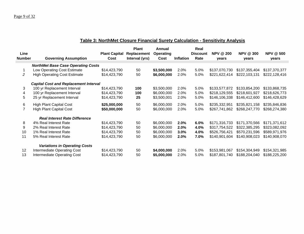
The most informative way to view the results of the NPV spreadsheet is to look first as the Base Case assumptions, then to perform some sensitivity runs changing the variables to see which of them have the most pronounced effect on the net present value of the financial assurance.
In Table 3: NorthMet Closure Financial Surety Calculation - Sensitivity Analysis, for the Base Cases it was assumed that the Real Interest Rate, the difference between the discount rate (5%) and inflation (2%), was 3 percent. This is a fiscally conservative, but realistic, assumption.
NorthMet Base Case Operating Costs
For the Base Case runs, assuming operating cost of $3.5 million/yr leads to a financial surety of about $137.4 million (line 1), and if the operating costs are $6 million/yr the financial surety would be $222.2 million (line 2) – for water treatment alone.
Capital Cost and Replacement Interval for the Water Treatment Plant
The NPVs are relatively insensitive to the capital replacement cost interval, as can be seen by comparing the NPVs in line 1 to line 3, and line 2 to line 4 of the Table, which vary by less than 3%. Going to a 25-year replacement schedule does make a 6.2% difference (comparing line 1 to line 5), but a 25-year replacement interval is too short to be realistic. The NPVs are also relatively insensitive to the capital cost of the treatment plant. If the capital cost is increased from $14.5 million (line 2) to $25 million, the increase in cost (72% cost increase, see line 6) results in only a 6% increase in the NPV; and, a capital cost increase to $50 million (245% cost increase, see line 7) results in only a 21% increase in the NPV.
Real Interest Rate – the difference between the rate of return and inflation
The spreadsheet is most sensitive to the Real Interest Rate. If the Real Interest Rate goes from 3% to 4%, the NPV of the financial surety goes down from $222.2 (line 2) to $171.4 million (line 8). On the other hand, if the Real Interest Rate goes from 3% to 2%, the NPV goes from $222.2 (line 2) to $323.1 million (line 9). If the Real Interest Rate goes from 3% to 1%, the NPV of the financial surety goes from $222.2 (line 2) to $590 million (line 10). The spreadsheet calculations are most sensitive to variation in the Real Interest Rate. This means that long term management of the financial surety corpus is very important, and that uncontrollable variations in the Real Interest Rate could significantly impact the corpus if it remains low for a significant period of time.
Variations in Water Treatment Plant Operating Costs
The NPV is marginally sensitive to change in operating costs. Increasing the operating costs from $3.5 million to $4.0 million per year, the NPV goes from $137.4 million (line 1) to $154.4 million (14% increase in operating cost, 12% increase in NPV – line 12). An annual operating cost of $5.0 million increases the NPV to $188.2 million (43% increase in operating cost, 37% increase in NPV – line 13).
The interest and return on investment rates are purely a choice that government agencies will make, and are not dependent on a mine plan. The operating costs do require a detailed calculation, but again the design for water treatment in the water management plan are going to be estimates no matter the final mine plan. A calculation of water treatment based on PolyMet’s proposed alternative would provide a very reasonable base for calculating operating costs for discussion in the SDEIS.
Recommendation: Because the interest and return on investment rates, and the operating costs, can make hundreds of millions of dollars difference in the financial surety required for the NorthMet mine, these assumptions/calculations should be made available for comment in the SDEIS.
Page 9 of 32
Table 3: NorthMet Closure Financial Surety Calculation - Sensitivity Analysis
Line Number Governing Assumption
Plant Capital Cost
Plant Replacement Interval (yrs)
Annual Operating
Cost Inflation
Real Discount
RateNPV @ 200
yearsNPV @ 300
yearsNPV @ 500
years
NorthMet Base Case Operating Costs1 Low Operating Cost Estimate $14,423,790 50 $3,500,000 2.0% 5.0% $137,070,730 $137,355,404 $137,370,3772 High Operating Cost Estimate $14,423,790 50 $6,000,000 2.0% 5.0% $221,622,414 $222,103,131 $222,128,416
Capital Cost and Replacement Interval3 100 yr Replacement Interval $14,423,790 100 $3,500,000 2.0% 5.0% $133,577,872 $133,854,200 $133,868,7354 100 yr Replacement Interval $14,423,790 100 $6,000,000 2.0% 5.0% $218,129,555 $218,601,927 $218,626,7735 25 yr Replacement Interval $14,423,790 25 $3,500,001 2.0% 5.0% $146,106,338 $146,412,600 $146,428,629
6 High Plant Capital Cost $25,000,000 50 $6,000,000 2.0% 5.0% $235,332,951 $235,821,158 $235,846,8367 High Plant Capital Cost $50,000,000 50 $6,000,000 2.0% 5.0% $267,741,862 $268,247,770 $268,274,380
Real Interest Rate Difference 8 4% Real Interest Rate $14,423,790 50 $6,000,000 2.0% 6.0% $171,316,733 $171,370,566 $171,371,6129 2% Real Interest Rate $14,423,790 50 $6,000,000 2.0% 4.0% $317,754,522 $322,385,295 $323,082,09210 1% Real Interest Rate $14,423,790 50 $6,000,000 3.0% 4.0% $526,756,421 $570,231,596 $589,971,97611 5% Real Interest Rate $14,423,790 50 $6,000,000 2.0% 7.0% $140,901,604 $140,908,023 $140,908,070
Variations in Operating Costs12 Intermediate Operating Cost $14,423,790 50 $4,000,000 2.0% 5.0% $153,981,067 $154,304,949 $154,321,98513 Intermediate Operating Cost $14,423,790 50 $5,000,000 2.0% 5.0% $187,801,740 $188,204,040 $188,225,200

Page 10 of 32
4.2.14.2.2 Development of the Existing LTVSMC Tailings Basin
In a discussion of the 2W tailings cell, it is noted:
“…in Cell 2W, rapid construction in later years of development resulted in oversteepened dams on all sides of Cell 2W. Some seepage has occurred from the dam in this and other areas along the dam embankments. Other points along the dam embankments have been subject to erosion of the perimeter dam due to the leaking and failure of LTVSMC discharge pipes, and from the natural geomorphological processes such as melting snow, precipitation runoff, soil creep, wind erosion and others.” (SDEIS, p 4-371)
There is no indication that this issue will be addressed as a part of reclamation.
Recommendation: A plan to address the oversteepening of the embankments of Cell 2W should be included in the closure/reclamation plan.
5.2.7 Air Quality
5.2.7.1.3 Proposed Action Emissions
Dust Suppression
The SDEIS identifies that “water and other dust suppressants” will or may be used - but does not specify when and where (see e.g. section 5.2.7.1.3 Proposed Action Emissions, SDEIS p. 5-401). Water alone can help suppress dust but for roads and similar flat wind-erosive surfaces it is recommended that calcium or magnesium chloride or similar suppression enhancer be required in the water used for dust suppression to extend the durability of the treatments. The Air Quality Management Plan similarly calls for “water and/or MPCA approved dust suppressants”
Recommendation: Unless there is a compelling environmental or safety reason, water (or snow) should not be used alone as a dust suppressant and instead magnesium chloride or similar suppression enhancer should be added to water to enhance dust suppression.
Recommendation: The mine should investigate and, where appropriate, mitigate reports of airborne dust that come from any entity, whether a mine employee or observer off the mine site.
In SDEIS Section 5.2.7.1.3, Proposed Action Emissions, PolyMet voluntarily agrees to:
“… accept emission limits below the major source threshold (stationary sources less than 250 tpy for criteria pollutants and 100,000 tpy for GHGs) so as to be classified as a synthetic minor PSD source and therefore not be subject to PSD requirements including modeling attainment with PSD increments for permitting purposes.” (SDEIS, p 5-402)
This lower threshold (higher permitting stringency) is described as based on the assertion that:
“NorthMet Project Proposed Action does not have projected controlled emissions above major PSD thresholds on an annual basis.” (SDEIS, p 5-402 [emphasis added]).
Annual averages are convenient for permitting purposes but it will be critical as part of the air quality permitting process and during mine monitoring to ensure that short-term air quality criteria are not exceeded.

Page 11 of 32
Recommendation: The mine’s air quality permit and air monitoring protocol should ensure that short term and peak air quality conditions are measured, representative, and reported to the public and regulatory agencies to ensure that short-term peaks, whether or not they violate standards, are considered as part of air quality degradation.
5.2.7.2 NorthMet Project Proposed Action
5.2.7.2.1 NAAQS and Prevention of Significant Deterioration Increment Impact Analysis
Mine Site Receptors Analysis
The waste rock pile is anticipated to present significant contaminating potential. The plan anticipates that dormant portions of the pile will be covered when not active (while being loaded before being covered and later while being transported to the pit for final disposal). Because the waste rock is highly reactive it stands to reason that its dust, notably fugitive dust, may be highly reactive. Therefore, the Mine Plan should review and analyze the reactivity of fugitive dust from waste rock sources (piles, handling, transport, etc.). If this review and analysis indicates the potential for degraded air quality or the potential for fugitive dust to contaminate lands or waters it travels to, then the regulatory agencies should take appropriate steps to halt such fugitive dust. Recommendation: Waste Rock fugitive dust should be reviewed and analyzed to ensure that it does not
pose a special hazard or threat to human health or the environment (beyond the typical opacity or other visual considerations).
5.2.7.4.3 Voluntary Mitigation Measures
The SDEIS discusses a voluntary anti-idle program (section 5.2.7.4.3, Voluntary Mitigation Measures, p. 5-434). The mine should commit to this program, even with the caveats described in that section, to help ensure that it is doing all that it can to reduce air pollution. Anti-idling will most impact sulfur- and nitrogen emissions, which come from trucks, locomotives, and mining equipment. The company should further ensure that its truck deliveries comply with the program. It is good for the SDEIS to describe PolyMet’s consideration, but it is hollow to describe unless the company commits to it.
Recommendation: The SDEIS should detail PolyMet’s actual commitment to an anti-idling program that maximizes reduction of vehicle-based NOx and SO2 emissions while accommodating mine-based requirements for productivity and safety.
5.2.7.2.5 Mercury Deposition Impact Analysis
Autoclaves, which are the main processing node of the hydrometallurgical processing, can be a significant source of airborne mercury. Autoclaves typically operate at temperatures in the hundreds of degrees. They use injected pure oxygen to actually ‘burn’ pyrite and other sulfides to produce this heat. As a result, any mercury that is in the ore is typically volatilized, and must be removed from the off-gas stream from the autoclave. PolyMet is proposing to use first stage and second stage scrubbers to remove mercury volatilized in the off-gas from the autoclaves (Barr 2012r, p 26). Third stage controls are available, but have been judged to be uneconomical by Barr/PolyMet (Barr 2012r, p 27). There is only a brief discussion of the mercury air emission control processes that will be employed at NorthMet (SDEIS, p 5-431). It is mentioned several places in the SDEIS that annual emissions from the autoclaves will be 4.1 pounds of mercury, after first and second stage controls, but there is no discussion in either the SDEIS

Page 12 of 32
or the primary technical support document (Barr 2012r) of the total amount of mercury in the process stream (bulk tailings, hydrometallurgical tailings, or autoclave scrubber waste).
It is important to know how much mercury is in the system, where it is going, and how stable it will be in its final form. This information should be disclosed in the SDEIS, and not buried in technical documents.
The scrubber mercury waste will be placed in the hydrometallurgical tailings facility, but this is not mentioned in SDEIS, only in the reference documents. This is significant process step and should be discussed in the SDEIS.
Recommendation: There should be a discussion in the SDEIS of the total amount of mercury in the process stream (bulk tailings, hydrometallurgical tailings, or autoclave scrubber waste), and where the autoclave scrubber waste will be disposed.
One of the major concerns with these capture systems is ensuring that they are performing as planned. Under USEPA standards mercury emissions from autoclaves are monitored only once a year. The performance of some high temperature components in the processing stream can be based only on manufacturer’s specifications with no monitoring. Once a year measurements will not provide enough data to ensure statistically reliable measurements of the efficiency of the mercury capture systems.
GAO reported that equipment to monitor mercury air emissions on a continuous basis was installed on 16 boilers at coal-fired power plants and used for monitoring operations and compliance reporting. On average these systems operated about 90 percent of the time.1 The technology for measuring mercury economically and often enough to provide meaningful data is available.2
Recommendation: In order to ensure that the mercury capture systems on the autoclaves are functioning as designed, a monitoring scheme should be required that will provide statistically reliable data on the autoclave mercury emissions.
5.2.8 Noise and Vibration
As part of the SDEIS’ noise impact methodology the regulatory agencies should require noise contour maps, notably regarding the Boundary Waters recreational areas, so that the public can fully assess the noise impacts that could occur offsite, particularly to federal and state recreational lands.
Recommendation: The SDEIS should include noise contour maps depicting offsite noise contours from mine activities (including transportation to and within the site) and cumulative noise impacts.
The SDEIS fails to discuss specific types of noise, which could impact people off-site differently than just measuring impacts by straight decibel levels. The SDEIS focuses primarily on volume but noise impacts are also impacted by four primary factors:
1. Tonality. Tonal noises which have a narrow sound frequency, such as the whine of an electric motor or an electric saw. A tonal audibility or annoyance factor may be calculated by comparing the tone level to the level of the surrounding spectral components.3
1 Mercury Control Technologies at Coal-Fired Power Plants Have Achieved Substantial Emissions Reductions, Report to the Chairman, Subcommittee on Clean Air and Nuclear Safety, Committee on Environment and Public Works, U.S. Senate, United States Government Accountability Office, October 2009, GAO-10-47 Clean Air Act, p. 26. 2 Mercury and Modern Gold Mining in Nevada, Greg Jones, Glenn Miller, Dept. of Natural Resources and Environmental Sciences, Final Report to U.S. Environmental Protection Agency Region IX, October 11, 2005, p. 26. 3 See Breul and Kjaer. 2000. Environmental Noise Handbook, p. 25. (http://www.macavsat.org/pdf_files/misc_reports/bk.pdf)

Page 13 of 32
2. Low Frequencies. Low frequency noise emits from machinery, all forms of transport and turbulence, turbines, exhaust gas, compressors, etc., and can travel greater distance than audible noises. Low frequency noise may cause notable human disturbances even when the decibel level (the sound pressure level) is below 30 dBA.4
3. Fluctuating Noise. Fluctuating or intermittent sounds are inconsistent in time and/or duration. Examples include generators or machinery operated in cycles, etc. Fluctuating noise has been shown to increase the annoying aspects/annoyance factor of the noise (notably when compared to average sound levels).5
4. Impulsive sounds. Impulsive sounds are brief, abrupt noises that can cause startling effects that cause greater annoyance levels than may be expected from just measuring the sound level.6 An impulsive sound at mine sites would be blasting noises, but could also include metal on metal, rock on rock, or rock on metal noise (such as dumping rock from a loader onto a transport truck, railcar, or rock pile).
The SDEIS should further consider types of noise, rather than simply volume level (decibels) or the conclusion that applicable standards will not be violated.
Recommendation: In addition to decibel (volume) impacts, the SDEIS should consider the potential for impacts from tonality, low frequency noises, fluctuating noise, and impulsive sounds. The focus should consider the Boundary Waters recreation areas but could also consider other land uses around the mine site.
5.2.14 Geotechnical Stability
5.2.14.2.2 Tailings Basin
In discussing the construction of the new tailings facility, it is noted:
“The Tailings Basin would be constructed using the upstream method, whereby NorthMet dam embankments would be constructed using preferentially borrowed LTVSMC tailings on top of the existing LTVSMC tailings embankment and on the spigotted tailings adjacent to the perimeter embankment.” (SDEIS, p 5-561)
Upstream construction poses the highest risk for seismic and static failure of tailings dams. Most tailings dam failures have been associated with upstream dam construction.
A significant concern with upstream tailings dam construction is its susceptibility to failure during earthquakes. If the tailings upon which the dam is constructed are saturated with water, the tailings do not form a stable foundation for the dam under seismic loading.
Tailings are placed in a saturated state. Tailings materials are relatively uniform in their size and shape, and typically have very low permeability, a fact often cited by mining engineers to argue that liners are not needed for tailings facilities. As a result, it will be difficult to consistently drain the water from all the tailings under the proposed dam expansion.
4 Berglund, B., Lindvall, T. and Schwela, D. 1999. Guidelines for Community Noise. Page 46. World Health Organization. 5 Leventhall, G. 2003. A Review of Published Research on Low Frequency Noise and its Effects. Prepared for Department for Environmental Foods and Rural Affairs. (United Kingdom). p. 11. 6 Breul and Kjaer. 2000, p. 14.

Page 14 of 32

Page 15 of 32
Continuing to use upstream-type dam construction methods to increase the capacity of the tailings at the NorthMet tailings facility is the least expensive dam construction approach, but poses the most risk to long term seismic stability.
PolyMet picked a “critical” cross section, noting:
“Geotechnical conditions along the length of existing LTVSMC Tailings Basin dams have varying layers of coarse, fine, and slime tailings. Cross Section F, which intersects the northern dam of Cell 2E, as shown in Figure 5.2.14-4, was selected to represent the critical cross section for stability analysis purposes as it is the maximum section and some layers of the weaker fine and slime tailings extend close to the dam embankment, and the dam embankment is underlain by peat.” (SDEIS, p 5-565)
(see Figure 5.2.14-5: Cross Section F of the Tailings Basin at Maximum Extent)
The dark blue segment in Figure 5.2.14-5 is the existing tailings dam, and the lighter blue would be the new upstream raises. This figure illustrates very well the importance of the stability of the tailings as a base for the upstream dam.
It is then noted in the SDEIS:
“The results reported in Geotechnical Data Package Volume 1 Version 4 indicate that the proposed design of the Tailings Basin would meet all respective Factors of Safety as required (PolyMet 2013n).” (SDEIS, p 5-565)
There are several problems with the otherwise good work in Geotechnical Data Package Volume 1 Version 4:
1) The Probabilistic Seismic Hazard Analysis (PSHA) considers the 2,475-year return seismic event to be the largest earthquake the dam will experience. The PSHA should have used the Maximum Credible Earthquake (MCE) as the design earthquake.
The design earthquake should represent the ground motions or fault movements from the most severe earthquake considered at the site. Since a tailings dam must stand in perpetuity, the design earthquake should be equivalent to the Maximum Credible Earthquake.
The estimated largest earthquake that could occur at any given location is called the Maximum Credible Earthquake. The MCE is defined as the greatest earthquake that reasonably could be generated by a specific seismic source, based on seismological and geologic evidence and interpretations. The Maximum Credible Earthquake is most often associated with a recurrence interval of 10,000 years.7
If the MCE/10,000-year event is used for the analysis of the 2,475-year event, the horizontal acceleration (horizontal g-force the dam is subject to) will increase significantly.
2) The mean distance to the nearfield earthquake is 100 miles. Probabilistic determination for the size of the largest earthquake is appropriate, but the assumption of 100 miles for nearfield is going to make the horizontal acceleration used to design the dam lower than what it should be.
The further away the tailings dam is from the location of the earthquake, the less energy the tailings dam will need to withstand in order to maintain its structural integrity. The closer the location of the
7 Large Dams the First Structures Designed Systematically Against Earthquakes, Martin Wieland, ICOLD, The 14th World Conference on Earthquake Engineering, Beijing, China, October 12-17, 2008

Page 16 of 32
earthquake to the tailings dam, the higher the cost of building the dam, because the closer the earthquake the more energy the dam will have to withstand.
Seismologists know that there are many active faults that have not been mapped or have been mapped inaccurately, that some faults believed to be inactive may actually be active, and that there are many inactive faults that may become active again. Because of these considerations, probabilistic methods are the more conservative way to determine the magnitude of a Maximum Credible Earthquake for dam analysis.
For tailings dams the most conservative choice for the location of the Maximum Credible Earthquake would be what is sometimes referred to as a ‘floating earthquake’ on an undiscovered fault that passes very near the site of the dam. This is a way of recognizing that we do not know the present, future, and even the past locations of significant faulting, and associated earthquakes.8 The conservative choice for a Maximum Design Earthquake would be a Maximum Credible Earthquake that ruptures the ground surface on which the dam is built.
3) The evaluation for dam stability does not employ dynamic modeling.
Polymet did not perform dynamic modeling for the tailings dams.
“Results of the seismic liquefaction screening evaluation (Section 6.5.3.3) indicate that seismic triggering will not occur. As the seismic design event (2,475-year return period) would not trigger liquefaction in any FTB materials, per the Work Plan (Attachment A), no additional seismic triggering analyses were necessary.” (Geotechnical Data Package Volume 1 – Flotation Tailings Basin Version 4, PolyMet Mining, April 12, 2013, p 92, emphasis added)
PolyMet performed what might be termed a pseudostatic analysis. Today, most US regulatory agencies will not accept pseudostatic methods for seismic design of new dam projects. Dynamic analysis of seismic loading for most new dams is required if the maximum credible earthquake produces a peak ground acceleration of more than 0.1 g at the site.9
A pseudostatic analysis (sometimes called seismic coefficient analysis) should only be considered as an index of the seismic resistance available in a structure not subject to build-up of pore pressure from shaking. It is not possible to predict failure by pseudostatic analysis, and other types of analysis are generally required to provide a more reliable basis for evaluating field performance.10
An example of a government agency which happens to focus on dam safety and that will not accept pseudostatic analysis is the Federal Energy Management Agency (FEMA). FEMA practice previously allowed the use of the pseudostatic method of analysis in areas of low or negligible seismicity. FEMA does not recommend the pseudostatic analysis to judge the seismic stability of embankment dams.11
8 Safety of Dams, Flood and Earthquake Criteria, Committee on Safety Criteria for Dams, Water Science and Technology Board, Commission on Engineering and Technical Systems, National Research Council, National Academies Press, Washington, D. C. 1985 9 http://www.meadhunt.com/documents/newsletters/persp_water3.pdf, downloaded on 14Jan10 10 Federal Guidelines for Dam Safety Earthquake Analyses and Design of Dams, Federal Energy Management Agency, May 2005, p. 35 11 Federal Guidelines for Dam Safety Earthquake Analyses and Design of Dams, Federal Energy Management Agency, May 2005, p. 38

Page 17 of 32

Page 18 of 32
Dynamic analysis is the most rigorous method of evaluating dam survivability under seismic loading. Typically a dynamic analysis will use finite element or finite difference programs such as TARA (Finn et al 1986), FLAC (Itasca Group 2002), or PLAXIS (PlaxisBV 2002) in which dynamic response, pore-pressure development, and deformations can be fully coupled.12
These tailings dams must contain this material in perpetuity. If not, the cost of collecting spillage due to an earthquake-related failure, and rebuilding the containment structure, would be many millions of today’s dollars. This is not a risk, or cost, that should be passed on to future generations. If these containment structures are going to be built, the assumptions used to check the design should be conservative, and the models the best available.
5.2.14 Geotechnical Stability
5.2.14.2.3 Hydrometallurgical Residue Facility
Global Slope Stability
As described above with the tailings basin geotechnical design, similarly there was no dynamic modeling for the hydrometallurgical facility.
“Liquefaction analysis was not applicable and not performed because the material proposed in the constructed dams would be well-compacted and the Hydrometallurgical Residue Facility liner system would limit leakage through the dams.” (SDEIS, p 5-575)
Even though the construction of the hydrometallurgical facility dam is downstream, the safest type of dam construction, the material that this facility holds is potentially very dangerous to both human health and the environment – if it were to be released. As a result, the geotechnical analysis of the dam should be conservative, and as with the bulk tailings dam, dynamic modeling should be performed.
In addition, it is proposed that the hydrometallurgical facility be placed on a residual layer of taconite tailings.
According to SDEIS Figure 5.2. 14-6 above a large portion of the hydrometallurgical facility (and liner system) will lie on: “Coarse Tailings with Layers of Fine Tailings, Fine Tailings with Layers of Slimes; Slimes with Layers of Fine Tailings; Fill – Interlayered Concentrate, Tailings, and Silty Sand; Silty Sand with Gravel; and, Peat.”
Even if this material will be “well-compacted” it would be safer to remove the original peat and silty sand/gravel, and the taconite tailings and slimes, and replacing this material with compacted fill, so that the hydrometallurgical facility is built on a well prepared and verifiably stable base. This is the conservative approach.
Recommendation: The underlying original ground and the taconite waste should be removed from underneath the hydrometallurgical tailings facility, an engineered stable base installed, and dynamic modeling performed on the hydrometallurgical dam.
12 See Federal Guidelines for Dam Safety Earthquake Analyses and Design of Dams, Federal Energy Management Agency, May 2005, p. 32

Page 19 of 32
APPENDIX B: Underground Mining Alternative Assessment for the NorthMet Mining Project and Land Exchange Environmental Impact Statement
2.0 Screening of the Underground Mining Alternative
The underground option was judged to be feasible technically, but not economically, based on the information in Table 2 Economic Assessment of a Sample of Underground Mining Scenarios Considered.
The table is fine as far as it goes, but there is no discussion of the sensitivity to change in metals prices. For example, what if the price of gold increased $500/oz. or copper increased $0.50/lb (both reasonable assumptions), how would that affect the net extracted metal value? Would this make the underground mine economic? If so, then an evaluation of an underground mine as an alternative would be warranted.
A typical technical analysis for a mine proposal, like the public securities documents and information filed by public companies in the SEDAR filing system.
The analysis in Appendix B does a partial job of assessing sensitivity, in this case the variables are limited to tonnage produced and operating cost, but it ignores variations in metal prices.
PolyMet’s NI 43-101 report does contain a limited cost sensitivity analysis,13 but a better and more typical example is Figure 18.8.5 below,14 where the sensitivity is also displayed graphically. Underground mining might be economical in the future with an increase in metals prices, and when the processing technology proposed for the NorthMet operation has been proven enough to clearly quantify the costs.
13 Updated NI 43-101 Technical Report on the NorthMet Deposit, AGP Mining Consultants Inc., January 14, 2013 14 Preliminary Assessment of the Pebble Project, Southwest Alaska, Ghaffari et al., Wardrop-Northern Dynasty Mines, February 17, 2011

Page 20 of 32
The environmental benefits of an underground mine would be significant – far less waste rock, and the potential to backfill most or all of the waste rock. It might also be possible under this scenario to limit or avoid long term water treatment, which would be a significant economic benefit that was not analyzed in the economics of the underground mine scenario.
Recommendation: A metals cost sensitivity analysis should be added to the Underground Mining Alternative Assessment to verify that the underground option is not economical with higher metals prices.
RECLAMATION PLAN (PolyMet 2013a, NorthMet Project Reclamation Plan, Version 3. January 22, 2013)
2.1.2 Rail Transfer Hopper (RTH)
The use of the East Pit as a repository (such as for sediment from the Rail Transfer Hopper (RTH) and process water pond (including ore remaining in the RTH, the OSP, or along the railroad tracks between them (PolyMet 2013a, section 2.1.2, p. 9)) underscores the importance of characterizing the wastes being placed there and then monitoring water that may pool/collect in the East Pit and waters (surface and ground) that may be hydrologically connected to the Pit.
Recommendation: All wastes that could be disposed in any pit, and the pits themselves, should be characterized to ensure that there will not be regular or seasonal contamination directly or indirectly to surface or ground waters.
2.1.5 Pipelines and Power Lines
The Reclamation Plan states: “Underground pipelines will be abandoned in place.” (PolyMet 2013a, section 2.1.5, p. 11). In general, abandonment may not be a problem but no pipeline should be allowed to remain if it could cause water to flow between two places where it should not, such as diverting water from a creek or connecting surface to ground water or connecting hydrologic units that are isolated from each other.
Recommendation: All pipelines proposed for abandonment in place should be evaluated to ensure that their residual contents will not cause contamination and that their presence cannot facilitate connectivity between otherwise isolated bodies of surface and/or ground water, whether constant or intermittent.
2.1.6 Tanks
The discussion about aboveground tank disposal appears reasonable. That section states: “Insulation and coverings will be removed and disposed appropriately.” (PolyMet 2013a, section 2.1.6, page 12) This statement implies compliance with applicable asbestos or other hazardous materials laws - but it would be more appropriate to expressly state that hazardous, toxic, nuclear and related materials will be disposed of in full compliance with applicable federal and state laws and regulations.
This comment applies to the entire Reclamation Plan, including this section and other sections that directly or indirectly include materials disposal (e.g. Sections 2.3 Special Material Disposal, 2.4 Product Disposal, etc.).
Page 21 of 32
Recommendation: The Reclamation Plan should expressly state the applicable federal and state laws, regulations, and rules that apply and that will be complied with in the testing, handling, storage, and disposal of all hazardous, toxic, nuclear, and related materials and wastes.
Recommendation: The Reclamation Plan should require a tracking system that demonstrates that materials are actually disposed-of according to the Reclamation Plan and applicable laws. The tracking system should include not only affirmation but documentation that certifies proper materials disposal.
3.0 Mine Site Reclamation and Long-Term Closure
3.1 Mine Pits
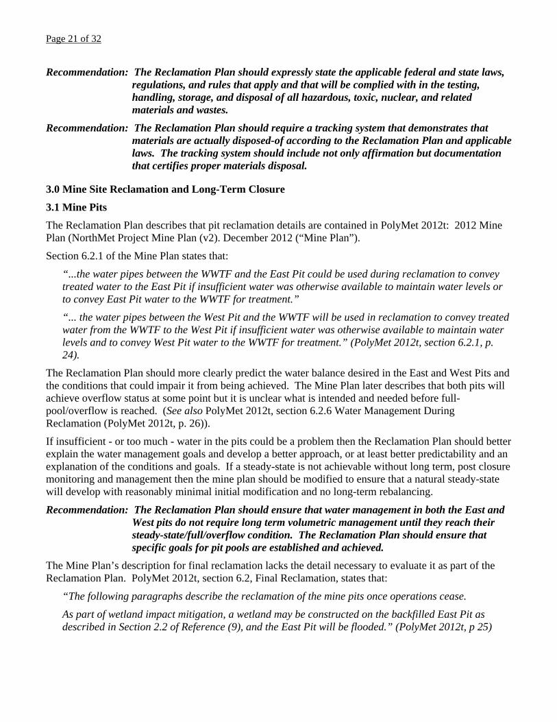
The Reclamation Plan describes that pit reclamation details are contained in PolyMet 2012t: 2012 Mine Plan (NorthMet Project Mine Plan (v2). December 2012 (“Mine Plan”).
Section 6.2.1 of the Mine Plan states that:
“...the water pipes between the WWTF and the East Pit could be used during reclamation to convey treated water to the East Pit if insufficient water was otherwise available to maintain water levels or to convey East Pit water to the WWTF for treatment.”
“... the water pipes between the West Pit and the WWTF will be used in reclamation to convey treated water from the WWTF to the West Pit if insufficient water was otherwise available to maintain water levels and to convey West Pit water to the WWTF for treatment.” (PolyMet 2012t, section 6.2.1, p. 24).
The Reclamation Plan should more clearly predict the water balance desired in the East and West Pits and the conditions that could impair it from being achieved. The Mine Plan later describes that both pits will achieve overflow status at some point but it is unclear what is intended and needed before full-pool/overflow is reached. (See also PolyMet 2012t, section 6.2.6 Water Management During Reclamation (PolyMet 2012t, p. 26)).
If insufficient - or too much - water in the pits could be a problem then the Reclamation Plan should better explain the water management goals and develop a better approach, or at least better predictability and an explanation of the conditions and goals. If a steady-state is not achievable without long term, post closure monitoring and management then the mine plan should be modified to ensure that a natural steady-state will develop with reasonably minimal initial modification and no long-term rebalancing.
Recommendation: The Reclamation Plan should ensure that water management in both the East and West pits do not require long term volumetric management until they reach their steady-state/full/overflow condition. The Reclamation Plan should ensure that specific goals for pit pools are established and achieved.
The Mine Plan’s description for final reclamation lacks the detail necessary to evaluate it as part of the Reclamation Plan. PolyMet 2012t, section 6.2, Final Reclamation, states that:
“The following paragraphs describe the reclamation of the mine pits once operations cease.
As part of wetland impact mitigation, a wetland may be constructed on the backfilled East Pit as described in Section 2.2 of Reference (9), and the East Pit will be flooded.” (PolyMet 2012t, p 25)

Page 22 of 32
Section 2.2 of Reference (9) is the NorthMet Project Wetland Management Plan (v3). January 2013, which is discussed in more detail below, and which does not contain the necessary detail or information to assess the mine’s plan in this area.
Recommendation: The Reclamation Plan should provide sufficient detail about wetlands construction and associated decision-making processes to allow regulatory agencies and the public to reasonably understand what is likely to happen and what criteria will be employed to determine reclamation success, and what steps will be taken in the even that reclamation does not achieve established criteria.
PolyMet 2012t, Section 6.2.3, Pit Perimeter Barrier, (PolyMet 2012t, p. 25) generally summarizes the types and placement of barriers around the pits. It does not, however, establish specific goals that will be collectively achieved by the barriers. The Reclamation Plan should specify that fencing will achieve an appropriate, reasonably measured barrier to access by people, including children, and wildlife. Some of this may be achieved by the referenced approval of the St. Louis County Mine Inspector but the mine company, and the Reclamation Plan bear the responsibility of establishing the reclamation criteria that will be achieved.
Recommendation: The Reclamation Plan should establish specific fencing goals to ensure that the barriers proposed in the Mine Plan will achieve an appropriate, reasonably achievable barrier to access by people, including children, and wildlife.
PolyMet 2012t, Section 6.2.5, Mine Pit Lake Level Management (PolyMet 2012t, p. 25-26), generally describes the pits and the excavated channel that will connect the East and West pits. The descriptions do not adequately ensure that the final plan will protect wildlife (that invariably will manage to enter the site in spite of the proposed barriers) that enters either pit or the excavated channel between them is able to reasonably escape.
Recommendation: The Reclamation Plan should plan for measures to allow animals to expressly rescue themselves should they fall into the pits or excavated channel between them. This should also include predicting the impacts and express protections for both terrestrial wildlife and birds that may land on contaminated waters. If contaminated waters present a reasonable threat to animals then additional measures should be committed-to and employed (such as hazing or surface netting for birds) to ensure that the pits do not become wildlife death traps.
Erosion
The Mine Plan’s Reclamation Maintenance section (6.3.1) describes that:
“Reclaimed mine overburden slope erosion will be corrected and re-vegetated as needed. In areas where excess erosion is a repetitive problem, channels and/or outfall structures will be designed for those specific locations.” (PolyMet 2012t, p. 26).
Neither the Reclamation Plan nor the Mine Plan describes adequate preventative reclamation methods to reduce overburden slope erosion or measures to ensure that erosion does not contaminate surface waters. The Reclamation Plan should describe detailed methods to be employed to prevent erosion. Should those methods prove inadequate then further planning and implementation should be employed. Methods to prevent erosion may include, but not be limited to, dozer basins, terraces, rock and rip-rap placement, etc. What matters is to ensure that prevention takes primacy over responses to failure.

Page 23 of 32
Where erosion does occur there should be a clear commitment to not only correct the cause/problem but to employ further preventative measures.
The Reclamation Plan should establish specific goals for erosion - the failure of which will trigger specified responses. Given that erosion may occur many years after successful revegetation (such as after a drought year stresses erosion-protecting plants or a particularly wet year or piping causes new or increased erosion) it is important for the Reclamation Plan to develop these goals and commitments.
Recommendation: The Reclamation Plan should establish clear, measurable erosion goals including success criteria(such as less than x-feet of rilling per y-area and no erosion wider or deeper than z-inches) and responses to failure to meet those reclamation criteria, including but not limited to treatment protocols; long-term protection from post-reclamation disturbances; timeframes over which success will be measured and how criteria failure or re-treatment activities will re-start timeframes, etc.
Stockpile reclamation is included in NorthMet Project Rock and Overburden Management Plan Version 5 (December 28, 2012), section 7.0 Reclamation and Long-Term Closure.
Wetlands
PolyMet 2012s, the Rock and Overburden Management Plan (v5, December 2012) section 7.1.2.2, Reclamation of Footprint (mitigation wetlands) states that:
“Once the waste rock and overburden are completely relocated from the temporary stockpiles to the East Pit, the stockpile bases, which include the overliner drainage system, liner system, underdrain system, if required, and portions of the foundation, will be disassembled for reclamation of the footprint. Generally, pipes, liners, and pumps, will be removed and the footprint of the stockpile will be reclaimed.
For the Category 2/3 Waste Rock Stockpile, wetlands will be restored or cultivated where the hydrology and soil conditions exist to support their development. Approximately 60 acres of wetlands have been identified within the Category 2/3 Waste Rock Stockpile footprint.
Wetland mitigation is expected to occur in areas that were wetlands prior to the start of stockpile development, as well as in additional areas where the stockpile load has depressed the soils enough that wetland hydrology can be established from prior upland areas. The plan for development of wetlands within these areas will likely include grading, the addition of soils as needed, and wetland plant propagation. The ultimate goal in restoration and development of wetlands within the former stockpile footprint will be to restore the original flow patterns that existed prior to mining and to establish an area of wetlands equal to or greater than existed prior to mining. See Section 2.2 of Reference (11) for more information on wetland mitigation at the Mine Site. For portions of the footprint that cannot be converted to wetlands, the surface will be scarified or soil will be placed over the reclaimed foundation, if needed, followed by seeding.” (PolyMet 2012s, p. 43).
The Reclamation Plan should make substantive analysis and establish specific goals regarding waste rock footprint reclamation. As written, the reclamation results could yield uncertain results with uncertain responses to failures if those results fail to achieve what should be pre-established goals. Given the importance of wetlands to the ecosystem and ecosystem function, their replacement should be paramount in the Reclamation Plan. Off-site purchase/protected wetlands is an excellent commitment - but does not replace the need for functioning wetlands in the local (on-site, post reclamation) ecosystem.
Page 24 of 32
The Reclamation Plan should predict the likely compaction caused by the waste rock and overburden piles and thereby calculate the necessary treatments needed to return them to productivity. The reference to scarification may not reach the depth of compaction without additional measures. The Reclamation Plan therefore should model/predict compaction rates and depths and commit to ensuring that reclamation activities reverse this compaction.
The Reclamation Plan should further commit to adequate testing and removal of contaminated soils to a ‘clean’ depth (depth at which contamination no longer exists) below the waste rock and overburden piles. This will be particularly important for the Class 1 waste rock but should apply to all materials that contain contaminants.
Finally the Reclamation Plan should establish wetland function goals that will be achieved. The commitment to try to re-establish the buried wetlands (under the waste rock and overburden piles) is good - but needs to be substantive and measurable, not simply a commitment to try.
The Rock and Overburden Management Plan refers to the Wetlands Management Plan v. 3 (Section 2.2 of Reference (11)). Version 3 was dated January 2013; Version 4 was dated March 2013 - therefore the latter is referenced here because it is more recent.
PolyMet 2013h, Wetlands Management Plan v. 415 states:
2.2.1 General Mine Area Wetlands.
“Upon reclamation, approximately 72 acres of wetlands may be created at the temporary mine stockpile areas after removal of the Category 2/3 Waste Rock Stockpile and the OSLA as described in Section 7 of Reference (5) (Large Figure 6). Because it may not be feasible to construct wetlands on the entire footprint of these temporary areas, it was assumed that only the area equivalent to the directly impacted wetlands within the footprints will be viable for wetland mitigation (Reference (1)). Design of wetland mitigation areas will be further evaluated in the detailed reclamation design in Section 7 of Reference (5). The design will include the preservation of upland buffer around the perimeter of the wetland mitigation areas.”
(PolyMet 2013h., pages 9-10 [emphasis added]).
The basis is unclear for the Plan to “assume” that any viable wetlands construction will be feasible, let alone the entire or partial footprint of the stockpile sites. The Reclamation Plan (and ACOE 404 permit analysis) should not count on what is currently a very limited and imprecise technology (wetlands construction) as an offset for 20 years of loss (during mining) and an assumed success of even a wetland footprint equivalent to what the mine will destroy. After 20 years of mining impacts he post-mining site will effectively be a “new” site. The constructed wetlands are not being reconstructed but rather are being constructed from scratch in a new hydrologic regimen (particularly with pit impacts to ground water quality, quantity, and flows).
15 Version 3 is largely unchanged, except for updating values:
“Upon reclamation, approximately 71 acres of wetlands may be created at the temporary mine stockpile areas after removal of the Category 2/3 Waste Rock Stockpile and the OSLA as described in Section 7 of Reference (5) (Large Figure 6). Because it may not be feasible to construct wetlands on the entire footprint of these temporary areas, it was assumed that only the area equivalent to the directly impacted wetlands within the footprints will be viable for wetland mitigation (Reference (1)). Design of wetland mitigation areas will be further evaluated in the detailed reclamation design in Section 7 of Reference (5). The design will include the preservation of upland buffer around the perimeter of the wetland mitigation areas.” (Wetlands Management Plan v. 3, p. 6).

Page 25 of 32
Recommendation: Constructed wetlands should be not be presumed successful for any footprint until they are constructed and successfully functioning, at the desired type and level, for at least 5-10 years. The Reclamation Plan should establish wetland size/volume and function goals that will be achieved. The commitment to try to re-establish buried wetlands should to be substantive and measurable, not simply a ‘commitment to try.’
3.0 Wetland Mitigation Outcomes
“This section documents the implementation of the Wetland Mitigation Plan. Wetland restoration construction progress will be tracked along with compliance with permit conditions. On- and off-site wetland mitigation monitoring and as-built reports will be summarized along with monitoring reports to document indirect wetland impacts in Section 4.0. Actual wetland impacts and compensatory mitigation will be tracked in this section as the Project progresses.”
There is a “PLACEHOLDER” in PolyMet 2013h for this section on Mitigation Outcomes, so it is not known what the mitigation outcomes will be.
Sections 4 (Monitoring) and 5 (Reporting) describe more about the wetlands but still do not establish the on-site goals and triggers necessary to ensure that reasonably predict on-site actions and successes - or the conditions necessary to determine that on-site wetlands cannot be restored, meaning that the sites will be simply revegetated.
The Wetlands Management Plan v.4 refers to a detailed wetland reclamation plan in “Section 7 of Reference (5).” This is:
5. —. NorthMet Project Rock and Overburden Management Plan (v5). December 2012.
Section 7 of the Rock and Overburden Management Plan is:
7.0 Reclamation and Long-Term Closure
It appears that taken together, the Reclamation Plan refers to the Rock and Overburden Management Plan, which refers to the Wetlands Management Plan, which refers back to the Rock and Overburden Management Plan. Collectively they seem to lack substantive detail and commitment necessary for the regulatory agencies and public to ensure that the Reclamation Plan will adequately reclaim the waste rock and overburden footprints, most importantly regarding wetlands.
The construction methods and measurements for wetlands success should be described in detail to ensure that the mine cannot simply spend years ostensibly constructing wetlands only to fail and “decide” to place cover material and revegetate - thus sacrificing onsite wetlands goals and functions (notably without clear criteria, steps to be taken, and decision process.
Recommendation: The Reclamation Plan should specify in detail the wetlands reclamation and restoration (and wetlands ‘replacement’) activities that will occur. It should further establish specific goals and standards that will be met, and establish specific responses to goals that are not met. Finally, it should establish the criteria to be used to determine that it is not possible or practicable to restore on-site wetlands so that the regulatory agencies and public can know in advance just what will happen and how decisions will be made.

Page 26 of 32
Section 7.1.2.2 of the Rock and Overburden Management Plan, Reclamation of Footprint (mitigation wetlands), states that:
“Once the waste rock and overburden are completely relocated from the temporary stockpiles to the East Pit, the stockpile bases, which include the overliner drainage system, liner system, underdrain system, if required, and portions of the foundation, will be disassembled for reclamation of the footprint. Generally, pipes, liners, and pumps, will be removed and the footprint of the stockpile will be reclaimed.” (PolyMet 2012s, page 43).
The Reclamation Plan should specify that the entire footprint of waste rock and overburden piles is removed and the entire site is reclaimed. As written, the above language commits only to generalities that collectively do not guarantee that the rock pile foundations and contamination will be fully removed.
Recommendation: The Reclamation Plan should commit to removing all waste rock and overburden pile facilities and all underlying materials that are contaminated or contain contaminated materials.
Monitoring
Rock and Overburden Management Plan section 7.3, Long-Term Closure, states that:
“After the reclamation process is complete, monitoring and maintenance of reclaimed areas will be done, as needed, in the spring and fall and as required by the PTM. If any of the sites have been damaged by erosion or suffered or experienced plant failure and need additional work, a plan will be created and implemented to repair the damage. This responsibility will continue until the release or partial release of PolyMet from the PTM responsibility. Of the areas at the Mine Site discussed in Section 7.1 and 7.2, the Category 1 Waste Rock Stockpile cover is the area that may require further maintenance in the long-term closure period.
However, monitoring of reclaimed surfaces will continue until the partial release or full release of these areas from the PTM responsibilities is granted. Long-term closure monitoring of reclamation wetlands is discussed in Section 4.2 of Reference (11).” (PolyMet 2012s, page 44-5).
The Reclamation Plan should contain specific commitments to monitoring (as reported in the PTM) but further identify specific goals that must be met before monitoring is reduced (or bond is released), the criteria used to measure those goals, and specific responses to failures to meet those goals. It is insufficient for the Reclamation Plan (or its referenced sections) to require only generalized commitments and nebulous responses to the failure to achieve those reclamation commitments.
Recommendation: All reclamation plans should be subject to full public and regulatory review prior to permitting and establish clear success criteria and responses to failure to meet those reclamation criteria. This should include, but not be limited to, plan-specific goals, objective criteria for each goal, timeframes over which success will be measured and how criteria failure or re-treatment activities should re-start timeframes, etc.
Recommendation: The reclamation plans should be reviewed and updated on a regular schedule, such as every 5 years, which will allow regulatory agencies and the public to monitor and predict reclamation success and issues and also allow for appropriate bond recalculation.

Page 27 of 32
For detailed information about water management system reclamation, the Reclamation Plan references PolyMet 2013e: the NorthMet Project Water Management Plan – Mine, Version 2 (January 9, 2013). The Water Management Plan section 7.1, Incremental Reclamation, provides that:
“Once reclamation in these areas is complete, the haul roads to these areas will also be scarified and seeded to allow continued access by small vehicles only for long-term monitoring.” (Water Management Plan, page 47)
It seems that this sentence mixes two different issues. One is revegetation and one is access. Revegetation plans, goals, and methods should stand on their own, details of which are discussed elsewhere in these comments. Separate from revegetation is road reclamation. It would be more clear and appropriate for the Reclamation Plan to comprehensively identify which roads will be maintained and how (e.g. revegetated but allowing small vehicle access, maintained large-access road, etc).
Recommendation: The Reclamation Plan should identify clear revegetation goals and methods, including revegetation standards, timetables, etc.
Recommendation: The Reclamation Plan should comprehensively identify all roads and clearly state how they will be reclaimed, including their short term and long term uses (or lack thereof).
Revegetation Criteria
Section 3.4 of the Reclamation Plan describes the cover material to be used for revegetation. It states:
“3.4 Building Areas, Roads and Parking Lots. After demolition of Mine Site buildings and parking areas, 2 feet of overburden material suitable for vegetation will be placed over the facility’s former footprint. Mine roads that are deemed not necessary for access by the MDNR Commissioner will be scarified and vegetated.” (PolyMet 2013a, p. 16)
The Reclamation Plan does not describe or commit to criteria for revegetation. The following criteria are therefore recommended for ALL sites to be reclaimed pursuant to the Reclamation Plan.
Topsoil Salvage and Placement
The higher the quality of topsoil (soil growth media) then the better the likelihood of successfully establishing durable vegetative covers. It is not clear what overburden material will be employed but rather than generalized names the Reclamation Plan should establish specific requirements for soils. This includes, but should not be limited to, pH, fertility, microbial biota, ratios of: sand/silt/clay, and nutrient cycles, such as for nitrogen and organic matter. Prior to mining, and based on pre-mine conditions, the Reclamation Plan should characterize the existing soils to guide the standards for post-mine soils. Specific topsoil requirements should be established to ensure that all growth media is suitable and will maximize the potential for revegetation success.
The greater the depth/quantity of topsoil (soil growth media) then the greater the chances of revegetation success. Long-term vegetation success will depend on greater soil depths compared to short-term vegetation success. Greater soil depth may not benefit revegetation success in the 5-year period of revegetation monitoring but greater soil depths is highly likely to benefit longer-term revegetation success. It would be a waste - and potentially impair long-term revegetation success to not salvage, preserve, and re-use all topsoil resources. Further it could impair long term revegetation success to not ensure that all sites have sufficient growth media.

Page 28 of 32
The benefits of high quality and high volume topsoil are different from the mine and the public. For the mining company, the extra benefit may not be realized because the company seeks the return of its bond and then it will leave the site forever. For the public - increasing revegetation success is highly valuable - and it is the public that will ultimately be responsible for the site when the company leaves. Therefore, it is important to ensure that all soils materials are salvaged and effectively used for reclamation and that where the original materials are deficient that alternative, quality topsoil is secured.
Recommendation: All soil material should be salvaged, stored, accounted for, and distributed to maximize revegetation potential.
Where multiple materials will be used, such as topsoil placed over non-contaminating rock (waste rock or otherwise) it is important to ensure that the Reclamation Plan accounts for size/fractionation differences between the different materials. Quarried or ‘clean’ overburden/waste rock can be very course compared to the other materials. If fine materials, such as topsoil are placed over course materials such that the material sizes are very different, the smaller materials placed on top of the larger materials can form a layer that appears stable but over time (ranging from weeks or months to many years) may form pipes (piping) or simply infiltrate (fall) into the larger material. For this reason, the Reclamation Plan should ensure that operators and inspectors are aware of the problems associated with disparate size fractions when materials are being placed. This is particularly important for topsoil, which can be particularly susceptible to infiltrating/falling into spaces below it during storm events, snowmelt, and freeze/thaw cycles.
Recommendation: The Reclamation Plan should establish general criteria and guidance to ensure that materials placement where topsoil is replaced does not allow small size materials to be placed on materials that have much larger size particles. Where this could happen, an interlayer of mid-size materials should be placed between them.
The Plan and permit should require salvaging all topsoil and subsoil from areas disturbed by mining activities - regardless of location or volume. Post-mine plant growth and establishment benefit substantially from maximizing plant growth media (soils), particularly where agriculture is a proposed post-mine land use. The more soil, the better the post-mine revegetation success, particularly in the first five years.
The best reclamation practice would be for the company to salvage existing soil materials in two lifts - the first being A and B horizons and the second lift being sub-B-horizon. During reclamation (re)placement, the lower horizons should then be placed as the first step of replacing cover material, upon which the upper (A and B horizons) would be placed. The net effect is more cover material that will better support plants and more quickly further develop soils than just the A and B horizons placed on top of sand, waste rock, liners, etc.
The topsoil salvage piles will stand unused for years. As a result the soils quality will degrade during mine operations and the soil value will be reduced from when it was salvaged compared to when it is replaced. To preserve soil integrity (including organic materials, microbes such as mycorrhizae, promote aeration, reduce weed introduction, and reduce erosion, the Reclamation Plan should identify specific steps that it commits to employ to establishing ‘nurse’ crops on the topsoil salvage piles. These plants should be consistent with, and not compete, with the planned postmine revegetation, especially agricultural seeding/planting.

Page 29 of 32
The Reclamation Plan should analyze and the company should commit to characterizing stored topsoil resources (one or two years prior to starting reclamation) to identify basic physical and chemical characteristic. These results can then be used to modify the reclamation plan and determine what, if any, amendments are necessary and appropriate to enhance and ensure revegetation success. Criteria should include material size fractions, nutrients, pH, microbial condition (such as mycorrhizae), and organic content. Sampling should be done at the surface and deep in the piles. This will ensure that the replaced soil and subsoil materials/horizons are best able to support post-mine agricultural goals. By sampling and evaluating the materials before they are disturbed, the mine can mix-in organics and other materials/amendments that may be necessary to ensure they are fully integrated into the replaced soils (as compared to simply added as top-dressing).
Recommendation: The Plan should develop detailed topsoil salvage and storage plans to ensure that the maximum amount of materials is salvaged for reclamation. These materials should be stored to maximize soil health and reclamation efforts. To ensure that all viable growth media is salvaged, characterization of materials should include field observation and not solely rely on a ‘standardized’ depth measurement.
Reclamation Maintenance
Reclamation Plan section 6.2, Reclamation Maintenance, provides that:
“Monitoring and maintenance of all reclaimed areas, including mine slopes, Mine Site stockpiles, Area 5 stockpiles, Plant Site Building Areas, the FTB and the HRF, will be inspected at least twice per year, as necessary, or as required by Minnesota Rules , part 6132.5200. Any areas that have been damaged by erosion or that have lost vegetation will be identified and plans to make repairs or reseed will be developed and implemented.
Inspection and repair will continue until the MDNR determines that the reclamation is stable and self-sustaining and issues a release of the permittee as outlined in Minnesota Rules, part 6132.1400 and 6132.4800. See Large Figure 2 for Plant Site Building Areas and Large Figure 16 for locations of reclaimed areas at Area 5....” (PolyMet 2013a, p. 26 [emphasis added])
Necessity can be indicated by an existing problem or by hindsight. It is unclear in this context how the mine may interpret “as necessary” but it is suggested that inspection be based on a decreasing schedule based on need. In the first two years after construction, reclaimed sites should be monitored (at least) monthly to ensure that problems are detected early-on. Where no problems are evident for one year those inspections may be reduced to quarterly. Where no problems are evident after two years of quarterly inspections then the inspection frequency may be reduced to twice per year. The timing should be reasonably based on capturing problems early-on and should be approved by the state regulatory agencies. If a problem is detected that requires remedial action then the inspection schedule should restart for that site.
Recommendation: Inspection of reclamation at all sites should be based on a decreasing schedule of frequency that begins with a monthly or every-other-month schedule and reduces to quarterly after one year and semi-annually after two years of each inspection schedule without the need for remedial actions. If remedial actions are required then the inspection schedule should re-start for that site.

Page 30 of 32
Revegetation Plan
Reclamation Plan Attachment A, Reclamation Seeding and Mulching Procedure, describes many important features for seeding and mulching. However, it fails to establish a quantifiable revegetation plan or criteria for revegetation success. The Reclamation Plan should, at a minimum, establish basic revegetation plans and criteria that can be applied as a basis to all sites to be revegetated (where modification is necessary it can be so-described in the particular section of the Reclamation Plan.
The Reclamation Plan should establish specific goals for essential revegetation features and not just generalized, conceptual goals. There should be clear noxious weed criteria, based on basal and aerial cover, which should be used to trigger treatment and/or retreatment.
Vegetation cover goals should be established. Further, the percentage cover should be required to persist for at least 5 consecutive years prior to bond reduction or release. Plant growth (germination and early growth) is not as important as long-term establishment.
Because post-mine land uses will not be homogenous, it will be important to establish criteria for both alpha and beta diversity. Such criteria should make clear both aerial and basal cover-percent and further identify criteria for success and failure for both alpha and beta diversity. Without these standards revegetation could achieve some goal or required percent coverage but not establish, or even provide a reasonable ecological basis for future establishment of the diverse vegetative cover that will persist and support post-mine land uses. These standards should roughly mimic the pre-mine alpha and beta diversity numbers for the mine, broken down into appropriate sub-regions. The goal should be to ensure that both species numbers and richness are established - which is necessary to achieve post-mine land use goals.
The 5-year period described s for bond reduction/release should re-start whenever revegetation activities are taken to enhance revegetation. The goal of any minimum period should be reasonably demonstrating that plants have established and are self-sustaining. If supplemental activities are taken (such as watering, adding amendments, fixing erosion or subsidence, recontouring, reseeding, planting, weed control, etc.) then the clock should re-start to ensure that vegetation is actually surviving on its own. The 5-year period should demonstrate the site’s ability to sustain itself - not demonstrate that with various treatments the company can keep the site growing.
Recommendation: Establish clear noxious species/weed criteria, including the lowest amount of weeds that will trigger treatment and the highest allowable percentage of noxious weeds that will be allowed for bond reduction/release.
Recommendation: Establish minimum percentage vegetative cover goals of at least 50% after three years and 80% for five years before determining “success” or allowing relevant bond release.
Recommendation: Establish clear alpha and beta diversity requirements for vegetative cover.
Recommendation: Revegetation success should be measured no sooner than five years after revegetation goals have been met - without additional treatments or activities. If additional treatments or activities are undertaken, the 5-year clock should restart to ensure that revegetation and long-term plant establishment has actually occurred.

Page 31 of 32
Weed Plan
The Reclamation Plan does not establish a detailed weed control plan, but weeds could significantly threaten the post-mine land uses. Weed problems can begin during the first stages of mining, particularly during topsoil salvage operations and establishing nurse crops, when weeds can begin to take hold.
Recommendation. A weed-prevention program should be developed and implemented. At a minimum, this plan should include, but not necessarily be limited to:
Certification of weed-free seed;
Processes to prevent weed introduction (such as washing vehicles entering the site);
Weed-response plan identifying how weeds will be controlled if they do come to the site.
Commitment to Reporting
It is important that the public be able to participate in all phases of mine permitting, operations, closure, and post-closure activities. To support this need, monitoring and discharge reports, including reporting on contamination of surface and ground water, should be made publicly available in a timely manner.
The mine should immediately notify the public of leaks, contamination, etc., and develop a system for such timely notification in a way that is broadly accessible to all affected parties. This is essential for trust and to develop a working relationship with the public, especially affected communities. Adequate monitoring is the only way to determine spills and their impacts. Unknown leaks, or leaks that employees fail to report or attempt to hide will remain undiscovered and their contamination will continue or disperse unless monitoring is in place to detect them. Adequate monitoring before, during, and following mining also protects the company, because it allows all involved to determine what is caused by the mine versus other sources/causes.
Before permit issuance, actual monitoring points for all monitoring should be clearly identified in terms of location and times of sampling. Moreover, monitoring points should be representative and be close to the discharge, to prevent long mixing zones that may become essentially sacrifice zones.
Recommendation. Contaminant release and incident reporting structures should require that the company provide environmental data and reports to the public. There should be full transparency and the company should commit to informing the public and government about any unplanned or unpermitted releases as soon as it becomes known - not just during the regular document/reporting cycle. Annual or even quarterly reports do not adequately address the public’s right to know about problems at the mine. These are essential for good operating procedures and public trust.
Thank you for the opportunity to comment on this Supplemental Draft EIS.
Sincerely;
David M. Chambers, Ph.D., P. Geop. Stuart M. Levit, M.S., J.D.

Page 32 of 32
References Supplied as a part of these Comments:16
A Review of Published Research on Low Frequency Noise and its Effects, Leventhall, G., prepared for Department for Environmental Foods and Rural Affairs (United Kingdom), 2003
Environmental Noise Handbook, Breul and Kjaer, 2000 (http://www.bksv.com/doc/br1626.pdf)
Federal Guidelines for Dam Safety, Earthquake Analyses and Design of Dams, Federal Emergency Management Agency, May 2005
Guidelines for Community Noise, Berglund, B., Lindvall, T., and Schwela, D., World Health Organization, 1999
Large Dams the First Structures Designed Systematically Against Earthquakes, Martin Wieland, ICOLD, The 14th World Conference on Earthquake Engineering, Beijing, China, October 12-17, 2008
Mercury and Modern Gold Mining in Nevada, Greg Jones, Glenn Miller, Dept. of Natural Resources and Environmental Sciences, Final Report to U.S. Environmental Protection Agency Region IX, October 11, 2005
Mercury Control Technologies at Coal-Fired Power Plants Have Achieved Substantial Emissions Reductions, Report to the Chairman, Subcommittee on Clean Air and Nuclear Safety, Committee on Environment and Public Works, U.S. Senate, United States Government Accountability Office, October 2009, GAO-10-47 Clean Air Act
Preliminary Assessment of the Pebble Project, Southwest Alaska, Ghaffari et al., Wardrop-Northern Dynasty Minerals, February 17, 2011
PolyMet 2012s, NorthMet Project Rock and Overburden Management Plan, Version 5. December 28, 2012
PolyMet 2012t, NorthMet Project Mine Plan, Version 2. December 14, 2012
PolyMet 2013a, NorthMet Project Reclamation Plan, Version 3. January 22, 2013
PolyMet 2013e, NorthMet Project Water Management Plan – Mine, Version 2. January 9, 2013
PolyMet 2013h, NorthMet Project Wetland Management Plan, Version 4. Issue Date March 20, 2013, Report Prepared for PolyMet Mining Company
PolyMet 2013n, NorthMet Project Geotechnical Data Package - Flotation Tailings Basin, Volume 1, Version 4. April 12, 2013.
Safety of Dams, Flood and Earthquake Criteria, Committee on Safety Criteria for Dams, Water Science and Technology Board, Commission on Engineering and Technical Systems, National Research Council, National Academies Press, Washington, D. C. 1985 (294 pgs, available for reading but not copying online at http://www.nap.edu/catalog.php?record_id=288)
Updated NI 43-101 Technical Report on the NorthMet Deposit, AGP Mining Consultants Inc., January 14, 2013
16 The PolyMet references are not provided because they are references from the SDEIS. One reference, a book, Safety of Dams, Flood and Earthquake Criteria, is available online for reading but not copying.