csw-20 series operation manual - ian fellows limited ... · csw-20 series operation manual ian...
TRANSCRIPT

CSW-20 Series
Operation Manual
Ian Fellows Limited industrial weighing
technology
systems instrumentation
applications design


Ian Fellows Ltd. 2013 – CSW-20 Operation Manual Page 1 Revision B - Page Issue 008 Software Release PO6_036/136
WARNING Product Improvement Policy Ian Fellows Ltd operates a continuous product improvement policy. We are proud of the quality of our products and recognise that improvement is always possible. In our striving for perfection we reserve the right to implement changes to hardware, software and specifications. For these reasons the contents of this manual are subject to change without notice. All efforts have been made to ensure the accuracy of this manual. However, should any errors be detected, Ian Fellows Ltd. would greatly appreciate being informed of them. The above not withstanding, Ian Fellows Ltd. can assume no responsibility for any errors in this manual or their consequences.
Statement on Conformity In ‘Trade’ mode, CSW-20 configured with appropriate components, is able to conform to the Harmonised European Standard EN 45501. This standard is based on a worldwide accepted OIML Recommendation R76 ~ Non Automatic Weighing Instruments. CSW-20 type approval number is UK2677. In addition, it is built according to a strict ISO9001 Quality Assurance System and complies with EN55022 (Emissions), EN45501 Annex B (Immunity), and both SI2328:1994 and SI3260:1994 Electrical Safety directives. Certificates of conformity can be provided on request.
Manual Revision B Issue 008 07/01/2014 Series PO6000 Software. (PO6_036/136 ⇒) Ian Fellows Ltd. 3D/E Centurion Way Crusader Park Warminster BA12 8BT Tel +44(0)1985 218675 Fax +44(0)1985 218713 www.ianfellows.co.uk
This Manual aims to describe normal, or default, operation. The actual functionality of the installed instrument may differ dependent on the parameters modified by the installation and set-up engineers. If in doubt consult supplier about specific functionality.
For Manuals, Application notes, Approval Certificates and Declarations of Conformity Visit website
www.ianfellows.co.uk

Software Version History
Software Version
Changes Known Issues (may also apply in earlier versions)
PO6_024 Remote Tare could prevent subsequent cancel tare Alternative program compilations derived Baseboards 1155 rev C use PO6_02n Baseboards 1155 rev D on use PO6_12n
PO6_025/125 - Remote tare operation fixed - EX serial response made single digit (0/1/2) to be Lucid compatible
Use of ? chr for comms help, limits use in text strings
PO6_026/126 - 126 prepared for 'Flash ETR' options - modified handling of ? chr in serial comms - Help dump changed from ?? to ?* - DEAD acquire without clearing linearity adjust
- Flash ETR s/w not finished - RX bug for serial parity check (CP01/02) - Print bug when 'LinE'=1 (continuous 1st line print) - Analogue gain only adjusts when 'nEt'=0
PO6_027/127 - Programmable Mode Functions (FU) Introduced - Flash ETR implementation complete (PO6.127) - Fixed parity bug - Fixed Print bug for 'LinE'=1 - Fixed Analogue gain adjust if 'nEt'=1 - CTRF/HF default now 0 was 0C (Form Feed) - Serial FK response reverts to single digit - Changes to tare printing, SAT value now printed - New PM command for last printed SAT value
- Calibration routine can generate minor span error on systems using large deadweight with high resolution. - Slave display mode (ER80) no Print function available
PO6.028/128 - Flash implementation revised - see application note (now Lucid compatible only for operation in gross) - Fixed calibration inaccuracy possible with high deadweight + resolution
- ENGCFG:DLTR [DB] added for future factory use - Slave display mode, Print function restored - Suppressed late/spurious responses issued if serial commands sent when in menu or function modes
- PW command now echoes (if EE=1) as other commands - previous always suppressed echo.
- Status of simple trip o/ps can be reflected as bars on left digit of display
- Once enabled, flash on this version can only be disabled at factory.
PO6.029/129 - Flash disable at level 2 by menu item FLSH - Increased protection against corruption that could affect CPI units during power disruption
PO6.030/130 - Support for checkweigher lightbar (CM models). New parameter STEP[SP] enables & adjusts lightbar. - New [ME] serial command gives display ‘Message’ facility. - Revisions to setpoint entry (via menu or mode function), by default x10 res digit not now shown. SETD[SM] settings extended to permit previous method. - Tidied o/p states under menu/error modes. (Mainly SM 3 use) - Revised loopback self test routine. (factory use) and extended I/O test to cover future optional I/O
- Revised setpoint entry only applied for trade mode
PO6.031/131
- Revised setpoint entry applied for trade and non trade modes
- Remote display RMDS(ER) mode 20 could cause error loop at power on (Press TEST to skip)
PO6.032/132
- Fixed ER20 power up error - Changed Print Baud (PV) settings PV1 now 19200 baud (previous PV1 for print disable can now be set by PV10)
- Access level 2 (calibration etc.) only accessible by passcode not internal pushbutton - Parameter dump (XC1) leaves display blank until power off/on (or send serial ME cmd)
PO6.033/133
- Fix to permit level 2 access by pushbutton. Also reinstated SW cmd for serial read of pushbutton. - New parameter in SERIAL menu - LDGZ allows leading zeros in place of spaces in weight string. - New parameter in ENGCFG menu - UNPO permits selection of uni/bi polar display. Was previously unipolar (restricted negative range) now default is bipolar and can be restricted if required. - Fix parameter dump to complete cleanly.
- At power on always loads setpoint values for product code 1 regardless of last code. (Any Menu or Mode function updated)
PO6.035/135
-on power up, loads setpts for last product code used - Revised flash initialise to better suit latest devices.
-Deadweight inaccuracy when using extreme dead/gain -Serial errors on odd/even parity and 7 bit data
PO6.036/136 -Permit Flash Enable at access level2 without a code - NTEP parameter added for Handbook 44 approval - Accuracy of deadweight acquisition improved for high dead/gain applications - Corrections for odd/even parity and 7 bit data. - ME command permits embedded DP - Unsolicited diagnostic messages (eg DROPOUT) no longer sent. -mV/V displayed to 4dp - Misc tidying and improvements

Ian Fellows Ltd. 2013 – CSW-20 Operation Manual Page 3 Revision B - Page Issue 008 Software Release PO6_036/136
CSW-20 - Contents
1. GETTING STARTED 4 1.1 Panel Functions 4 1.2 Power Connection 6 1.3 Loadcell Connection 7 1.4 Control Outputs and Inputs 9 1.5 Printer & Comms Connections 11 1.6 Switching On 12
2. CALIBRATION & ADJUSTMENT 13 2.1 Calibration Sequence 13 2.2 Linearity adjustment 15 2.3 Virtual Calibration 15 2.4 Weight Filtering 16
3. MENU FUNCTIONS 18 3.1 Set Up Menus 18 3.2 Access Levels - Passcode & Pushbutton Entry 18 3.3 Selecting Menus and Accessing Parameters 19 3.4 Editing Parameters 20 3.5 Permanent Parameter Storage 20 3.6 Special Editing Procedures 21 3.7 Setting The Real Time Clock - Time & Date 22 3.8 Special PLU Parameter – Product Code 22 3.9 MODE FUNCTIONS - Selecting a Function for the MODE button 22
4. ADVANCED FEATURES 25 4.1 Using Tares (Net Weighing) 25 4.2 Setpoint Operations - overview 26 4.3 Simple Trip Mode - Setpoint Mode 07 (Default) 26 4.4 Checkweighing Modes - Setpoint Mode 00, 02, 04, 05, 06 26 4.5 Batchweighing - Setpoint Mode 01 28 4.6 Remote Operation (Control I/P assignment) 31 4.7 Control O/P and Printout Assignment 31 4.8 Part Counting 33 4.9 LIVE Animal Weighing 34 4.10 Conversion Mode 34 4.11 Analogue Output (Option) 34 4.12 Flow Rate Display/Output 35
5. SERIAL INTERFACING AND PRINTING 36 5.1 Serial/Printer Installation 36 5.2 Serial Comms ~ SErIAL_ Parameter Menu 36 5.3 Serial Interface Weight Data Format 37 5.4 Multi-drop Operation (RS 485 only) 39 5.5 Printer Config. ~ Pr_CFg_ Menu 40 5.6 Print Formatting ~ Pr_For_ Menu 41 5.7 Remote Displays/Port Assignment 44
6. DIAGNOSTICS 45
7. APPENDIX 47 7.1 Specifications 47 7.2 Calibration Transfer 48 7.3 Replacing Legends 49 7.4 Dimensions 49
8. MENU TABLES 50
9. BASEBOARD LAYOUT REFERENCE 54

Ian Fellows Ltd. 2013 – CSW-20 Operation Manual Page 4 Revision B - Page Issue 008 Software Release PO6_036/136
1. GETTING STARTED
1.1 Panel Functions
NET Semi-Auto or Preset TARE IN OPERATION.
(FLASHING, Display shows Net Totalised Weight).
GROSS GROSS WEIGHT Displayed. (FLASHING, Display shows Gross Totalised Wt).
Both Flashing: - Stored Weight Value (eg in Preset Tare register) - Total Number of Weighments.
ZERO GROSS WEIGHT IS WITHIN 0.25 division (‘e’) OF ZERO.
MOTION WEIGHT SIGNAL IS NOT STABLE (Functions requiring stability are disabled). (FLASHING (Menu Mode) ~ ASCII control character entry mode).
All flashing: Displaying message from remote PC [ME] command
The NET Wt. display is the GROSS Wt. - minus - the sum of any Preset Tare or Semi-Auto Tare. For more information on Preset Tares see section 4 The pushbuttons also have secondary functions ENTER used when displaying and editing parameters.
PRINT - Print or Store Weight (Subject to valid print conditions)
SEMI AUTO TARE - Tares to net zero (unless a Preset Tare is active) Press and hold for 1 second to CLEAR Semi Auto Tare. If Preset Tare is active, GROSS displays while pressed
TEST - Ten Times Normal Scale Resolution. (Only displays x10 while held pressed in Trade Mode. Toggles between x10 and x1 if in Non-Trade mode).
SET ZERO - Resets gross zero. Weight must be in gross mode, stable and within permitted Zero Setting Range
MODE/F1 - May action one of several selectable functions. See section 4 - Press and hold for 1 second to access SET-UP MENUS. See Section 3

Ian Fellows Ltd. 2013 – CSW-20 Operation Manual Page 5 Revision B - Page Issue 008 Software Release PO6_036/136
Display status indicators The normal weighing units of measurement are legended on the front panel. During normal operation - some status functions may be indicated by a flashing character in the left digit ~
CCCC = Count mode
rrrr = Rate mode
UUUU = Converted mode, converted Units.
.... = command pending ~ awaiting stable weight
NNNN = Peak mode max value
uuuu = Peak mode min value
---- = Negative Sign (could over-ride status byte)
The following only display if enabled by parameter IN_OUT STATIN_OUT STATIN_OUT STATIN_OUT STAT = 1
FFFF = Fail (Setpoint Mode SETDSETDSETDSETD = 00)
HHHH = High (Setpoint Mode SETDSETDSETDSETD = 02/04/05)
pppp = Pass (Setpoint Mode SETDSETDSETDSETD = 00/02/04/05)
LLLL = Low (Setpoint Mode SETDSETDSETDSETD = 02/04/05)
EEEE = Empty/Discharge (Batching mode SETDSETDSETDSETD = 01)
dddd = Dribble (Batching mode SETDSETDSETDSETD = 01)
bbbb = Bulk (Batching mode SETDSETDSETDSETD = 01)
MMMM = Horizontal bars reflecting status of simple trip o/ps (SETDSETDSETDSETD = 07)
Note: GROSS and NET indicators flash to indicate displayed Totals, Preset Tares and ‘Flash Alibi’ weights. ALL indicators flash if a remote PC has placed a ‘message’ on the display (using ME command, introduced at version PO6.030/130).

Ian Fellows Ltd. 2013 – CSW-20 Operation Manual Page 6 Revision B - Page Issue 008 Software Release PO6_036/136
1.2 Power Connection If not already pre-wired, connect incoming mains supply to terminals on SK2. Live to ‘L’; Neutral to ‘N’; Earth, attach an eyelet to end of wire and then to Earth Stud on the cover plate next to the cable gland. The earth connection then links as shown below. External supply should be fused according to supply cable capacity ~ typically 5 Amp.
Power Connection – revision E and earlier CSW-20 is usually supplied set for 230V (180-260V) operation unless specifically ordered (confirm by checking data plate). A replaceable internal fuse - T500mA (anti-surge) - is located at position F2 - configuration for 230V or 115V ac is possible by repositioning this fuse link– see below.
Position 1 - 230V
Conversion from 230V to 115V is possible by lifting
the fuse out and replacing in alternative position.
Earth Stud
Base Assembly.
Position 2 - 115V
Eart
h
Liv
e
Neu
tral
Lid Assembly.
Cable Gland.
Remark the Manufacturers Plate if changed.
Power Connection – revision F CSW-20 is usually supplied set for 230V (180-260V) operation unless specifically ordered (confirm by checking data plate). It is possible to configure for 115V ac by switching to the alternative position – see below.
Position 1 - 230V
Earth Stud
Base Assembly.
Lid Assembly.
Cable Gland.
Remark the Manufacturers Plate if changed.
Conversion from 230V to 115V is possible by
switching to the alternative position.
Position 2 - 115V
Ne
utr
al
Ea
rth
Liv
e
Ian Fellows Ltd. 2013 – CSW-20 Operation Manual Page 7 Revision B - Page Issue 008 Software Release PO6_036/136
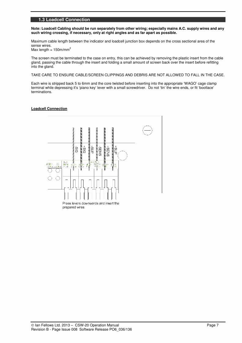
1.3 Loadcell Connection Note: Loadcell Cabling should be run separately from other wiring; especially mains A.C. supply wires and any such wiring crossing, if necessary, only at right angles and as far apart as possible. Maximum cable length between the indicator and loadcell junction box depends on the cross sectional area of the sense wires. Max length = 150m/mm
2
The screen must be terminated to the case on entry, this can be achieved by removing the plastic insert from the cable gland, passing the cable through the insert and folding a small amount of screen back over the insert before refitting into the gland. TAKE CARE TO ENSURE CABLE/SCREEN CLIPPINGS AND DEBRIS ARE NOT ALLOWED TO FALL IN THE CASE. Each wire is stripped back 5 to 6mm and the core twisted before inserting into the appropriate ‘WAGO’ cage clamp terminal while depressing it’s ‘piano key’ lever with a small screwdriver. Do not ‘tin’ the wire ends, or fit ‘bootlace’ terminations. Loadcell Connection

Ian Fellows Ltd. 2013 – CSW-20 Operation Manual Page 8 Revision B - Page Issue 008 Software Release PO6_036/136
6-wire Loadcell Cable Connection Schematic
4-wire Loadcell Cable Connection Schematic
It is essential that the ‘sense’ inputs are connected. Normally, 6 wires are taken to the loadcell junction box where the ‘sense’ wires are linked to the ‘excitation’ terminals. For direct 4 wire loadcell connection, the ‘sense’ inputs must be linked directly to the ‘excitation’ terminals inside the indicator.

Ian Fellows Ltd. 2013 – CSW-20 Operation Manual Page 9 Revision B - Page Issue 008 Software Release PO6_036/136
1.4 Control Outputs and Inputs The IO interface was updated and revised at Baseboard Rev E to permit output switching positive or negative. Connection information is described below. See section 9 at rear of manual - Baseboard Layouts - to identify terminal locations. For operation of I/O see section 4.
Input/Output Cable Screens It is recommended that screened multicore cables be used to connect to the various input contacts and output loads (use separate multicore cables for inputs and outputs). Ground cable screens to the cable gland at point of entry. Keep any unscreened portion of cable as short as possible to avoid electrical noise pick-up or radiation.
OUTPUTS 1, 2, 3 REV C Baseboard Terminals marked for outputs 4 and 5 are never used Recommended Interface The recommended option is to use an external DC supply. Be sure to fit ‘commutation’ diodes across any inductive load such as a relay coil. Without it the indicator’s opto-isolator transistor may be destroyed. Use screened cable and connect screen to the gland at point of entry. Do not connect screen at ‘load’ end of cable.
Each output load may draw up to 60mA (Load resistance >200Ω for 12v; >400Ω for 24v). The outputs consist of uncommitted darlington opto-isolators, capable of ‘sinking’ >60mA with a ‘drop’ of <1.5v when ‘on’, and will stand up to 30v without significant leakage when ‘off’. They are strictly DC, and the ‘OPn+’ must not go negative of ‘OP COM’, or damage to the output device will occur. If an output fails to switch, check the external wiring carefully, and the user programming of, for example ‘OPAL’, to be sure they are supposed to be operating. Recommended Interface - Common Positive Drive
Alternative Interfacing Below is an alternative scheme using the internal, unregulated supply ‘+VOUT’. This method has potential to create a ‘noise’ hazard, because it involves external connection to the internal supplies. However, if the distance is short; it may be done, with care. The actual voltage available at ‘+VOUT’ is variable dependent on the number of display segments illuminated, and other load factors. On a 230v supply, it will vary between 22v and 32v, on 115v; it may drop as low as 18v. However, it should be compatible with most industrial 24v rated inputs. +VOUT will supply typically up to 100mA (200mA if DAC option not fitted). Alternative Interface - Common Positive Drive

Ian Fellows Ltd. 2013 – CSW-20 Operation Manual Page 10 Revision B - Page Issue 008 Software Release PO6_036/136
OUTPUTS 1, 2, 3 REV E Baseboard Recommended Interface The recommended option is to use an external DC supply. Be sure to fit ‘commutation’ diodes across any inductive load such as a relay coil. Without it the indicator’s opto-isolator transistor may be destroyed. Use screened cable and connect screen to the gland at point of entry. Do not connect screen at ‘load’ end of cable.
Each output load may draw up to 60mA (Load resistance >200Ω for 12v; >400Ω for 24v). The outputs consist of uncommitted darlington opto-isolators pairs, capable of ‘sinking’ or driving >60mA with a ‘drop’ of <1.5v when ‘on’, and will stand up to 30v without significant leakage when ‘off’. They are strictly DC, and the ‘OPn+’ must not go negative of ‘OPn-’, or damage to the output device will occur. Each output incorporates a 100mA reset-able fuse - reset by power off and allow to cool. If an output fails to switch, check the external wiring carefully, and the user programming of, for example ‘OPAL’, to be sure they are supposed to be operating. Recommended Interfacing
Common Positive Drive -
Common Ground Drive -
Alternative Interfacing Below are alternative schemes using the internal, unregulated supply ‘+VOUT’. This method has potential to create a ‘noise’ hazard, because it involves external connection to the internal supplies. However, if the distance is short; it may be done, with care. The actual voltage available at ‘+VOUT’ is variable. It will vary considerably, dependent on the number of display segments illuminated, and other load factors. On a 230v supply, it will vary between 22 and 32v, on 115v, it may drop as low as 18v. However, it should be compatible with most industrial 24v rated inputs. We recommend that the available +VOUT supply is checked to ensure suitability for your use. It will supply typically up to 100mA (200mA if DAC option not fitted). Alternative Interface
Common Positive Drive - Common Ground Drive -

Ian Fellows Ltd. 2013 – CSW-20 Operation Manual Page 11 Revision B - Page Issue 008 Software Release PO6_036/136
INPUTS 1 and 2 Rev C and Rev E Baseboard Important Note :- Rev C baseboard Inputs are polarity dependent. (Connections marked: IP1+, IP1- & IP2+, IP2- ) Rev E baseboard Inputs are not Polarity dependent (Connections marked: IP1, IP1 & IP2, IP2 ) The normal method for connecting to the control inputs is from an external 12-24V DC power source, via the controlling contact or transistor. The switching current is 5-12mA. The contact or transistor may be in series with either input (observe correct polarity for the switching transistor if solid-state output, as well as the indicator input if REV C). As each input is fully isolated, they may be commoned to positive (where the external switching elements are commoned to ground – typically open collector NPN outputs), or to negative (eg open collector PNP outputs – like the example below). Special care should be taken with any relay contact selection, especially if 12v is used. Good quality, gold plated is recommended. Recommended Interface - Switching to negative Recommended Interface Switching to positive
Alternative Interfacing As with the output examples previously, there is an alternative, non-preferred scheme. Two examples are shown for positive and negative switching. These both use the internal, unregulated ‘+VOUT’. This is un-recommended because it involves external connection to the internal supplies; in some situations a ‘noise’ hazard. However, if the distance is short, it may be done, with care. The actual voltage available at ‘+VOUT’ is variable but it will reliably drive the control inputs. Alternative Interface - Switching to negative Alternative Interface - Switching to Positive
1.5 Printer & Comms Connections See section 9 at rear of manual - Baseboard Layouts - to identify terminal locations and designation. Further operational information is in section 5. Connections for most common PC and printer use will be as below Indicator to Printer
CSW-20 Baseboard Printer Function 9 Way ‘D’ 25 Way ‘D’
COM (ground) P3:10 - Comms Ground 5 7
PTX (transmit) P3:11 - Receive (RX) 3 3
PBUSY (busy) P3.12 - Busy (DTR) 6 20
Indicator to PC
CSW-20 Baseboard PC Function 9 Way ‘D’ 25 Way ‘D’
COM (ground) P3:7 - Comms Ground 5 7
TX (transmit) P3:8 - Receive (RX) 2 3
RX (receive) P3.9 - Transmit (TX) 3 2

Ian Fellows Ltd. 2013 – CSW-20 Operation Manual Page 12 Revision B - Page Issue 008 Software Release PO6_036/136
1.6 Switching On At switch-on, a display segment test is followed by:
Software Version number display e.g. PO6_022PO6_022PO6_022PO6_022 (give this number in event of a query).
Traceable Access Number display e.g. tAn 021tAn 021tAn 021tAn 021 (This number increments when changes are made to calibration – Requiring Access Level 2
Self testing of internal electronics; prom, eeprom, ram, a-d etc. will occur. Diagnostics indicate failures (see Section 6).
The system should then show a live weight display ready for use.
A display of --------20%20%20%20%-------- or --------4%4%4%4%-------- indicates the weight signal is outside currently permitted zero limits. In this case remove weight from platform until within limits and an auto-zero takes place, or press SET ZERO for display referenced from last stored zero position. Zero conditions at power on depend on current configuration.
Parameter ENG_CFG PONZENG_CFG PONZENG_CFG PONZENG_CFG PONZ [EP] determines if the system applies zero conditions at power on. 0= checks for weight within zero conditions and then performs auto-zero 1= no restriction, powers on with weight displayed
Zero limits are determined by
ENG_CFG CERTENG_CFG CERTENG_CFG CERTENG_CFG CERT [EX] Trade Mode 0= Non Trade Mode – zero limits at power-on are +/-10% band around calibrated zero point
SET ZERO function then operates over +/- 10% band around the zero position set at power on 1/2= Trade Mode – zero limits at power-on are +/-10% band around calibrated zero point
SET ZERO function then operates over +/- 2% band around the zero position set at power on
Parameter confiG z2pcconfiG z2pcconfiG z2pcconfiG z2pc [Z2] can modify the power-on zero range 0= +/- 10% range at power-on as above 1= +/- 2% range restriction at power on
TIP – A scale inadvertently loaded at power on, might auto-zero within the +/-10% range and when the weight is removed, drop below zero by more than the +/- 2% now permitted by the SET ZERO function. Powering on/off with the scale unloaded will rectify this situation, or it is also possible to press & hold SET ZERO and then at the same time press MODE

Ian Fellows Ltd. 2013 – CSW-20 Operation Manual Page 13 Revision B - Page Issue 008 Software Release PO6_036/136
2. CALIBRATION & ADJUSTMENT
If unfamiliar with general routines for accessing menus and editing parameters read section 3 first. The calibration facility allows full re-calibration from the front panel, checking of calibration validity without disturbing existing parameters, or is a valuable diagnostic tool for initial set-up and subsequent fault-finding.
Before initial calibration, decide what the scale range (Max/TOPTOPTOPTOP) and increment (e/DISPDISPDISPDISP) are to be. Selection is dependent on many factors and should be determined by experienced personnel. This is particularly critical for Trade Approved installations where compliance with Type Approval requirements is essential.
e/DISPDISPDISPDISP must be a sub-multiple of 1, 2 or 5, anywhere between 0.001 and 50.
2.1 Calibration Sequence The calibration menu differs from other menus in that as each stage completes, it automatically steps to the next
stage/item in the menu. A full calibration sequence would start at the first menu item (DISPDISPDISPDISP) and progress through the sequence. However, if appropriate, stages can be skipped by simply using keys to step through the menu. From weight display mode
Press MODE for 1 second to display PASSPASSPASSPASS. Obtain required Access Level using Passcode or
pushbutton and proceed to MAIN MENU USEr__USEr__USEr__USEr__
Then to select CALIbn_CALIbn_CALIbn_CALIbn_.
If Access Level is already 1 or 2 pass pass pass pass will not be displayed.
At passpasspasspass pressing internal pushbutton gains Access Level 2
Passcode 1 ENTER gains access level 1
Passcode 900 ENTER gains access level 2 if permitted
These are default passcodes and may be altered by installer
Level 2 Passcode access is permitted when ENG_CFG CERTENG_CFG CERTENG_CFG CERTENG_CFG CERT = 0/1
Press MODE again to enter the calibration menu. Unless the SECURITY ACCESS LEVEL is already 2, the message
pass pass pass pass (or PSHbUtPSHbUtPSHbUtPSHbUt ) will be displayed. This is a further request to key in the LEVEL 2 Password or press
the calibration button on the main board If adjustment is not intended; press MODE to skip this step. Items
within the calibration menu can then be examined but not changed.
dISP ~ Display Increment and Decimal Point ( ‘e’ ) Press MODE to show ‘increment’ (scale interval)
together with decimal point position, if applicable. Press or to step increment in sequence 1, 2, 5, 10, 20, 50, 1
... etc.
Press to step decimal point left (max 3 dp)
In Non Trade Mode extended 0 is shown in the LSD representing the resolution available with the x10 ‘TEST’ function
Press ENTER to set selection and move on …
toP ~ Maximum Display Capacity ( ‘max’ )
Edit using the keys
Press MODE to show current value for MAX CAPACITY.
Note: The display will be maintained for 9 divisions (e) beyond this value. Having changed this value, full calibration MUST be carried out.
Then press ENTER to set selection and move on…
FILt ~ Filter Band Parameter Shows current Filter Band Setting 00 - 05 or 10 Press MODE to Edit using the keys
If set to '00' then the band will be automatically selected during calibration. Alternatively may be set to '01' light filter through '05' heavy filter and will NOT be changed after Cal. A setting of '10' shows that the filter has been manually optimised
using the filter coefficient set by the Fltc Fltc Fltc Fltc parameter in the
ConFIg_ConFIg_ConFIg_ConFIg_ Menu
Press ENTER to set edited selection or to step past and move on….

Ian Fellows Ltd. 2013 – CSW-20 Operation Manual Page 14 Revision B - Page Issue 008 Software Release PO6_036/136
Fast ~ Fast Track Parameter
0 = OFF, Filter is always applied at a uniform rate 01= ON, Filter effect reduces when weight is ‘in motion’
Other settings 2+ reserved for future
Fast Track feature modifies how the weighing filter is applied.
See further information on Filtering later in this section. Press MODE to Edit using the keys
Note: Filling mode automatically handles the way in which the filter
applies during fill, FASTFASTFASTFAST setting will affect the behaviour before and after fill.
Press ENTER to set edited selection or to step past and move on….
Frez ~ Display Freeze Parameter Freeze feature latches on stable readings to prevent
flicker. See further information on Filtering later in this section.
Press MODE to Edit using the keys
0 = OFF, display tracks weight changes immediately 1 = ON, stable readings will latch for up to ~ 0.5s
Press ENTER to set edited selection or to step past and move on….
dead ~ Deadload Offset Calibrate Press MODE to show approx millivolt per volt
output from loadcell(s).
Excitation is approx. 5 Volts Ensure weigh platform is empty and stable, and the mV/V reading is as might be expected.
Zero Track and Set Zero are disabled until full calibration is completed
Press ENTER to initiate automatic DEADLOAD
acquisition. This will take several seconds. Deadload may be re-acquired without the need to re-acquire the
span - exit via TESTTESTTESTTEST to store the new value, for Verified Systems treat as re-calibration, unit will have to be re-verified.
Display will eventually show… or press to skip Deadload Calibration and reach …
CALAt ~ Enter Span Calibration Weight Press MODE to display currently defined Span
Calibration Weight value. Press MODE to Edit using the keys
For non-trade applications see also below "virtual calibration" Calibration weight may be between 12.5% (6.25 % when non-
trade) and 100% of the MAX (TOPTOPTOPTOP)
Press ENTER to set selection and move on …
CAL ~ Span Calibrate Press MODE to show approx millivolt per volt
output from loadcell(s) less the deadload offset
This is active output; i.e. 0mV/V is displayed if no calibration weight is loaded.
Ensure weigh platform is loaded with the previously selected CALAtCALAtCALAtCALAt calibration weight value, it is stable, and the mV/V reading is as might be expected
Press ENTER to initiate automatic SPAN acquisition. This will take several seconds.
For Trade mode, the loadcell signal must be ≥1µV for each division (e).
Display will eventually show…. Or press to skip span Calibration…
CAL may be skipped if it is only desired to re-acquire DEADLOAD on a previously calibrated system.
TIP - It is important that the millivolt/volt readings are close to expected values. A fault on the ‘SENSE’ signals from the loadcell may result in a millivolt reading 2~4 times higher than expected but give an otherwise, apparently ‘normal’ calibration. The result of setting up with a faulty ‘SENSE’ signal would be drifting and general instability of the weight reading.
Millivolt/volt reading = ‘CAL ’ weight x Loadcell Sensitivity(output) mv/V Loadcell Capacity No. of loadcells in weigher
Load cell capacity(rating) and sensitivity(output)can be obtained from the loadcell manufacturers specifications/certificate. E.G. Single 20kg, 2mV/V loadcell used in platform with 8kg ‘CAL’ weight. Millivolt reading = 8 x 2 = 0.8mV/V. 20 1

Ian Fellows Ltd. 2013 – CSW-20 Operation Manual Page 15 Revision B - Page Issue 008 Software Release PO6_036/136
tESt ~ Display Wt x10 (Fine Trim)
Enters a ‘SPAN TRIM’ mode (only if level 2), indicated by
flashing t.t.t.t. in MSD (with decimal point.).
Nudges span calibration factor up by one tenth of a division.
Nudges span calibration factor down.
Each ‘nudge’ moves the indicated weight, wherever nudging is done. Thus if scale is calibrated and nudged at 33% of capacity then each nudge will represent a change of three tenths of a division at full scale.
Pressing MODE puts into x10 weight display mode
with a flashing tttt in the display MSD, then~
The limit of 12.5% of capacity applies so nudging is inhibited below this weight.
Unless at ACCESS LEVEL 2, it is not possible to ‘fix’ any values obtained above.
If in Trade mode, or ENTER (except in tESttESttESttESt) will abort
calibration at any stage, restoring previous values (with the exception
of linearity parameters ~ see above). The display will show Abort?Abort?Abort?Abort? and pressing either again will cleanly abort leaving the old values intact. Pressing any other key will return operation to the calibration function just exited.
In non trade mode – pressing the ENTER key will bring up the
SURE?SURE?SURE?SURE? message and a second press of ENTER will store the new
values. Pressing instead of ENTER will bring up the Abort?Abort?Abort?Abort?
Message. A further press of the ENTER key or the key will restore
the old values.
See Section 7.3 for details of recording established calibration values for future use if service is required and calibration transfer has to be implemented.
ENTER or MODE ends the span trim procedure.
After calibration the Display interval can be altered without the
need for full re-calibration. dISPdISPdISPdISP located in the CALIbn_CALIbn_CALIbn_CALIbn_ menu can set a “pseudo” Display interval value - with the constraints that the decimal point cannot be moved.
Once back at the calibn_calibn_calibn_calibn_ menu heading, other menus may then be accessed, or the weight indication resumed by pressing ENTER (closing access level) or keeping the access level active for subsequent return to menus.
2.2 Linearity adjustment
In the ENGCFG_ENGCFG_ENGCFG_ENGCFG_ menu a 5 slope 6 point linearity adjust can be made at 20% LiN2LiN2LiN2LiN2, 40% LiN4LiN4LiN4LiN4, 60% LiN6 LiN6 LiN6 LiN6 and
80% lin8lin8lin8lin8 of capacity. To adjust take reading at 20/40/60/80 of capacity and note error in weight (e/10). If error was +8.2kg then at LRN2
enter –8.2kg to adjust. Adjustment is limited to a max amount equal to 12 scale divisions (12 x DISPDISPDISPDISP) Note: adjustment only affected between previous and next breakpoint e.g. in stated example between 0 and 40%
2.3 Virtual Calibration
Pressing when showing tESttESttESttESt in non trade mode enables Calibration via entry of the cell mV/V rating as an
alternative to conventional calibration. Displays SPAnSPAnSPAnSPAn and the value can be entered in units of 0.001mV/V.
If an accurate estimation of the active loadcell output in mV/V is available, this can be entered as a SPAnSPAnSPAnSPAn parameter.
A deadload step (without a subsequent CALCALCALCAL step) must have been performed previously; an ErrorErrorErrorError display or serial ‘?F’ error will be generated otherwise. The calculation is relatively straightforward.
SPAnSPAnSPAnSPAn value = Loadcell sensitivity x System Maximum Capacity No. of Loadcells x Individual Loadcell Capacity Loadcell Sensitivity is in Millivolts per volt (mV/V). The System Maximum Capacity is the gross weight it is designed to weigh, deadload is ignored. If a single 2mV/V 100kg cell is used in the bottomworks of a 60kg system, the active output of the cell (for maximum capacity) will be: 2 x 60 = 1.2 mV/V. Enter 1.200 to set the span. 100 Rather than using the loadcell manufacturers catalogue quoted nominal sensitivity, it is best to use the exact figures provided by the individual test certificate. In multiple cell applications, average the sensitivities of the cells.

Ian Fellows Ltd. 2013 – CSW-20 Operation Manual Page 16 Revision B - Page Issue 008 Software Release PO6_036/136
The limitations of this technique are: -
The indicator’s ADC internal gain varies slightly from device to device. An average millivolt conversion factor (determined from factory production test figures) is pre-programmed into the indicator. A worst case error might be around a quarter of a percent of full scale
The loadcell manufacturer’s sensitivity figure may be wrong or may be affected by other cell summing/cornering devices.
Because no proper test weighing takes place, obvious bottomworks problems such as binding are not exposed ~ the full load may not be reaching the loadcell.
An ErErErErrorrorrorror display means the sensitivity is too low.
Performing a normal CALCALCALCAL test weighing forces the SPAnSPAnSPAnSPAn parameter to 0. It is not possible to read back a meaningful value if a conventional span calibration is performed.
2.4 Weight Filtering
(See also lllliveiveiveive ANIMAL WEIGHING (4.9)) CSW-20 provides five powerful features for optimising weighing performance and display appearance to suit individual applications.
Filter – see FILTFILTFILTFILT & FLTCFLTCFLTCFLTC – adjusts the level of damping applied to the weight signal
Fast Track – see FastFastFastFast – enables fast track of large weight changes
Display Freeze – see FREZFREZFREZFREZ – holds a stable reading from unnecessary flicker
Motion Band – see MBNDMBNDMBNDMBND – affects the system conditions required for STABLE weight
Motion Delay – see MDlyMDlyMDlyMDly – delays action pending multiple stable integrations
Display Update – see UPDTUPDTUPDTUPDT – alters how often the display is refreshed
FILTFILTFILTFILT & FLTCFLTCFLTCFLTC parameters found in the CONFIGCONFIGCONFIGCONFIG Menu adjust the level of damping applied to the load cell signal. Inevitably more damping makes for slower reaction time to change in weight.
From the CONFIGCONFIGCONFIGCONFIG menu these parameters can be altered at Level 1 Access. The Filter Band (FILTFILTFILTFILT) is also in the calibration menu where level 2 Access is required to affect any change.
FILTFILTFILTFILT can be set from 01 for light damping to 05 for extremely heavy damping. A setting of 02 is likely to suit most applications.
Normally only FILTFILTFILTFILT (The Filter Band) will need to be altered, this automatically sets a value for FLTCFLTCFLTCFLTC (The Filter Coefficient) as shown in the table below:
Filter Band FILTFILTFILTFILT 01 02 03 04 05
Filter Coefficient FLTCFLTCFLTCFLTC 80 40 20 10 08
A Filter Band setting of 10 indicates a non-standard setting of the Filter Coefficient. A setting of 00 might be used during calibration, to allow the filter to self-adjust.
FastFastFastFast parameter, found in the CONFIGCONFIGCONFIGCONFIG (level 1 Access) and CALIBNCALIBNCALIBNCALIBN (Level 2 Access) menus can be used to speed up large changes in weight.
The Fast Track setting reduces damping while the signal is in motion, allowing faster weight change, then applies the current filter setting once weight has stabilised.
Fast Track must be set to suit the particular application or the way in which the scale is to be used. 0 = OFF, Filter is always applied at a uniform rate 01= ON, Filter effect reduces when weight is ‘in motion’ Other settings 2+ are reserved for future development
FREZFREZFREZFREZ parameter is used to turn on the Display Freeze feature. When the Display Freeze is active, a stable reading will be frozen to prevent unnecessary flicker. The Freeze is released after motion persists for ~ 0.5 sec. Any application that requires instant response to weight change will need the freeze turned off by setting
FReZFReZFReZFReZ to 0.

Ian Fellows Ltd. 2013 – CSW-20 Operation Manual Page 17 Revision B - Page Issue 008 Software Release PO6_036/136
Typical Fast/Freeze combinations
FASTFASTFASTFAST FreZFreZFreZFreZ TYPICAL APPLICATIONS
1= Display Freeze ON Catch Weight, Parcel Weighing 1= Fast Track ON
0 = Display Freeze OFF Load then adjust into tolerance, May also suit heavily damped scales such as weighbridges
1-8 = Display Freeze ON 0 = Fast Track OFF
0 = Display Freeze OFF Manual Dosing & Filling.
Note: CSW-20 Filling mode (SETDSETDSETDSETD 01) automatically handles the way in which the filter is applied during fill. However
FASTFASTFASTFAST & FReZFReZFReZFReZ settings will affect the behaviour before and after fill. For example if weight might need manual top up
after fill set FASTFASTFASTFAST =0 (Off)
mbndmbndmbndmbnd parameter, found in the CONFIGCONFIGCONFIGCONFIG menu (level 2 Access) can be used to relax the conditions defining stability.
By default mbndmbndmbndmbnd = 0 and can only be changed at Level 2 Access. This is designed to ensure that the weight signal is truly stable before operations such as Print or Tare are performed.
Less stringent conditions may suit some applications. Increasing MbndMbndMbndMbnd (range 1-7) relaxes the conditions for stability such that dependent functions will act quicker though the weight might still be changing. Thus a Print
could occur before the final weight is reached. A Legal for Trade application would use mbndmbndmbndmbnd = 0.
mdlymdlymdlymdly parameter, found in the CONFIGCONFIGCONFIGCONFIG menu (level 2 Access) can be used to further condition actions that depend on stability.
mdlymdlymdlymdly 0 Tare/Print operations perform regardless of motion
1 Default - Tare/Print operations will perform on seeing a single stable weight integration as determined by motion band and filter settings
2-9 Motion will continue to be flagged until 1-9 successive ADC stable cycles have been recorded (each cycle is 20ms) TIP – helps prevent premature tare/print especially when using heavy filters or when motion band is not zero
UPDTUPDTUPDTUPDT parameter, found in the CONFIGCONFIGCONFIGCONFIG menu (level 1 Access) sets the rate at which the display (and serial interface transmission) is refreshed. It does not otherwise affect the speed of operation (ie setpoints, printing etc.)
07 08 09 10 UPDTUPDTUPDTUPDT 00 01 02 03 04 05 06
Non Trade Only
Update rate (S) 0.02 0.1 0.04 0.3 0.4 0.5 0.6 0.7 0.8 0.9 1.0
The display rate should be chosen for the application. Most platform and bench scales would use the default 03 whereas a weighbridge may suit a slower rate such as 06. Manual dosing applications benefit from faster rate (01). Very fast rates (00 & 02) demand a lot of processing time and should be avoided except for diagnostic purposes.

Ian Fellows Ltd. 2013 – CSW-20 Operation Manual Page 18 Revision B - Page Issue 008 Software Release PO6_036/136
3. MENU FUNCTIONS
3.1 Set Up Menus The basic operator functions and displays are illustrated in section 1.1 and section 4 gives information on quick access functions that can be configured on the MODE key. Many additional functions and features are accessed using ‘Set Up Menus’.
To access the menus, press and hold MODE for 1 second - the display shows PASSPASSPASSPASS A pass code or use of the internal pushbutton switch will now determine the access level (permissions) to be granted. Once within the menu system, the five front panel buttons will operate according to their secondary functions MODE ENTER
3.2 Access Levels - Passcode & Pushbutton Entry Parameters within the menus are protected by different ACCESS LEVELS - Most parameters can be read at any access level, but may only be edited at the specified access level or higher. Access Level
Class Procedure
0 General User Parameters eg Time/Date, Product Code…
1 Installer/Supervisor eg Most configuration parameters, totals clear…
Level 1 code - At PASSPASSPASSPASS prompt enter code
Default = 1 :- ENTER or serial command PW1
2 Installer/Engineer eg calibration and other restricted configuration parameters
Internal pushbutton if ENG_CFG CERENG_CFG CERENG_CFG CERENG_CFG CERTTTT=2 ;
Level 2 code if ENG_CFG CERTENG_CFG CERTENG_CFG CERTENG_CFG CERT=0/1
At PASSPASSPASSPASS or PshbutPshbutPshbutPshbut prompt, press internal pushbutton or enter code if permitted,
Default = 900 :- ENTER or serial command PW900
3 Factory only (some can be edited at level 2 by holding internal pushbutton when pressing ENTER)
If higher access is not required, PSHbUtPSHbUtPSHbUtPSHbUt and PASSPASSPASSPASS can be skipped by pressing MODE or ENTER without other entry.
Pushbutton
The internal pushbutton for level 2 (S1) is located on the baseboard inside the unit.
See baseboard diagram at rear of this manual (Position reference 3) Pass codes
Codes are up to 4 digits long and are entered using the keys and the ENTER button. Codes are entered from right to left, the actual digits are not displayed, a dot shows as each digit is set.
Each digit can be cycled up 0-1-2… or down 0-9-8… using . Step to the next left using .
EXAMPLE - code “900” could be entered
Display Key
PASSPASSPASSPASS .
PASSPASSPASSPASS . .
PASSPASSPASSPASS . . . ENTER
Access2Access2Access2Access2
or more easily:
Display Key
PASSPASSPASSPASS .
PASSPASSPASSPASS . .
PASSPASSPASSPASS . . . ENTER
Access2Access2Access2Access2 (The access level is shown while the ENTER key is held pressed)
Default level 1 code is '1' - alter with SPAS SPAS SPAS SPAS in conFIg_conFIg_conFIg_conFIg_
Default level 2 code is '900' - alter with cPAScPAScPAScPAS in engcfg_engcfg_engcfg_engcfg_
Level 2 is required to alter either code - Always set codes before sealing of instruments for trade use.

Ian Fellows Ltd. 2013 – CSW-20 Operation Manual Page 19 Revision B - Page Issue 008 Software Release PO6_036/136
Once an access level is obtained it remains effective so long as the system remains in menu mode.
Return to weighing mode using the key, keeps the access level effective. This allows the effect of changes to be investigated before returning into the menus without having to re-apply passcode/pushbutton. After 4 minutes in weighing mode, without operation of any function or at power off, access will reset to level 0 automatically.
Return to weighing mode using the ENTER key immediately resets access to level 0
3.3 Selecting Menus and Accessing Parameters
On initial entry to the menus the first
menu title USEr___USEr___USEr___USEr___ is displayed
Step up or down through the available menu titles using the keys.
At access level 0, only a subset of the available menus are displayed.
At access level 1 and above the full menu set becomes available.
Two special menus ANALOG_ANALOG_ANALOG_ANALOG_ and
FLASH_FLASH_FLASH_FLASH_ only appear when these options have been enabled.
The figure opposite gives a brief explanation of the features found in each menu. Full details of the parameters within each menu will be found in the diagrams at the back of this manual.
With the desired menu group selected, press MODE to access the parameters in the menu. (Depending on current access level,
passpasspasspass/pshbutpshbutpshbutpshbut may also be
prompted at entry to the CALibn_ CALibn_ CALibn_ CALibn_
andengcfg_engcfg_engcfg_engcfg_ menus.)
The parameters within a menu are stepped through with keys.
The parameter name may be displayed, along with a one or two digit value. If its value is more than two digits long, MODE must be pressed to display & edit it.
DESCRIPTION
MODE
At ACCESS LEVEL 0 (no password) the menus below are hidden
Batch__Batch__Batch__Batch__
Count__Count__Count__Count__
User___User___User___User___
CALIbn_CALIbn_CALIbn_CALIbn_
Totals_Totals_Totals_Totals_
Calibration procedure
Batch and check-weighing setpoints
Part Counting
Time/Date, Tares, Product code, Code/Run no etc
Totalisation
Pr_cfg_Pr_cfg_Pr_cfg_Pr_cfg_
Serial_Serial_Serial_Serial_
Config_Config_Config_Config_
Pr_for_Pr_for_Pr_for_Pr_for_
Engcfg_Engcfg_Engcfg_Engcfg_
Printout formatting and text strings
Printer port characteristics and conditions
Serial comms port & remote display settings
Installer set-up parameters
Factory & engineer parameters
In_Out_In_Out_In_Out_In_Out_
Analog_Analog_Analog_Analog_
FLASH__FLASH__FLASH__FLASH__
Button_Button_Button_Button_ Enable/disable panel functions
Configure control I/O operations
Analogue Output operation and calibration
Electronic Tally Record (Alibi)
MENU
Ian Fellows Ltd. 2013 – CSW-20 Operation Manual Page 20 Revision B - Page Issue 008 Software Release PO6_036/136
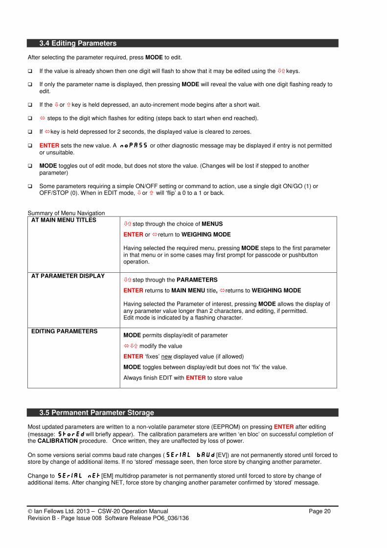
3.4 Editing Parameters After selecting the parameter required, press MODE to edit. If the value is already shown then one digit will flash to show that it may be edited using the keys. If only the parameter name is displayed, then pressing MODE will reveal the value with one digit flashing ready to
edit. If the or key is held depressed, an auto-increment mode begins after a short wait. steps to the digit which flashes for editing (steps back to start when end reached). If key is held depressed for 2 seconds, the displayed value is cleared to zeroes.
ENTER sets the new value. A noPASSnoPASSnoPASSnoPASS or other diagnostic message may be displayed if entry is not permitted or unsuitable.
MODE toggles out of edit mode, but does not store the value. (Changes will be lost if stepped to another
parameter) Some parameters requiring a simple ON/OFF setting or command to action, use a single digit ON/GO (1) or
OFF/STOP (0). When in EDIT mode, or will ‘flip’ a 0 to a 1 or back. Summary of Menu Navigation
AT MAIN MENU TITLES step through the choice of MENUS
ENTER or return to WEIGHING MODE Having selected the required menu, pressing MODE steps to the first parameter in that menu or in some cases may first prompt for passcode or pushbutton operation.
AT PARAMETER DISPLAY
step through the PARAMETERS
ENTER returns to MAIN MENU title, returns to WEIGHING MODE Having selected the Parameter of interest, pressing MODE allows the display of any parameter value longer than 2 characters, and editing, if permitted. Edit mode is indicated by a flashing character.
EDITING PARAMETERS MODE permits display/edit of parameter
modify the value
ENTER ‘fixes’ new displayed value (if allowed)
MODE toggles between display/edit but does not ‘fix’ the value.
Always finish EDIT with ENTER to store value
3.5 Permanent Parameter Storage Most updated parameters are written to a non-volatile parameter store (EEPROM) on pressing ENTER after editing
(message: StorEdStorEdStorEdStorEd will briefly appear). The calibration parameters are written ‘en bloc’ on successful completion of the CALIBRATION procedure. Once written, they are unaffected by loss of power.
On some versions serial comms baud rate changes (SERIAL BAUDSERIAL BAUDSERIAL BAUDSERIAL BAUD [EV]) are not permanently stored until forced to store by change of additional items. If no ‘stored’ message seen, then force store by changing another parameter.
Change to SERIAL NETSERIAL NETSERIAL NETSERIAL NET [EM] multidrop parameter is not permanently stored until forced to store by change of additional items. After changing NET, force store by changing another parameter confirmed by ‘stored’ message.

Ian Fellows Ltd. 2013 – CSW-20 Operation Manual Page 21 Revision B - Page Issue 008 Software Release PO6_036/136
3.6 Special Editing Procedures Negative Number Entry Occasionally a parameter requires a negative value entry (eg Inflight and some engineering parameters). To set the negative sign, step to the most significant digit (left most character). This digit only, steps through the numbers and then the '-' sign, allowing this to be set. N.B. Setpoints cannot be entered in negative format. Hexa-decimal data ‘Hexa-decimal’ characters are simply an extension of the normal 0-9 numbering system giving 16 options, rather than 10 and go from 0 -through-9, then A, B, C, D, E & F. Entry is as for normal numbers; the software automatically recognises when the selected parameter is in hex format and allows the keys to step through all 16 ‘digits’.
Hexa-decimal data is used mainly for Print Formatting and the ADC Configuration parameters found in the EngCFg_EngCFg_EngCFg_EngCFg_ Menu. Alpha-numeric data entry Where a parameter requires an alpha-numeric entry the procedure is slightly modified ~ To make entry easier, text strings are entered from the left instead of from the right as with numeric and hexa-
decimal values. If the key is held pressed for 2 secs, alpha strings clear to spaces. The increment/decrement sequence is 0-9, A-Z using UP, or a-z going DOWN, ‘Esc’ (1Bh), ‘EOS’ code (1Fh),
‘space’ code (20h). Alpha characters are represented by a ‘stylised’ 7 segment character set (see note below). Lower case characters are indicated by the presence of a steady ‘.’ (decimal point). To enter a lower case ‘a’ use
the up arrow 11 times (to step to ‘B’) then step back using the down arrow key to ‘A’. Approaching any letter from above makes it lower case, going up to a letter makes it upper case. Watch the d.p. turning ON and OFF.
Non-printing control characters (special entry routine; see below) are displayed as ‘ ¯ ’ The ‘EOS’ code (ascii 1Fh ~ looks like ‘ ’) is an optional ‘end-of-string’ terminator (any following characters,
including any in ‘Stxb’ if ‘EOS’ appears in ‘StxA’, will not be printed). NOTE: The 7-segment display uses a stylised alphabet. Most letters are obvious but the following are cryptic:
= J = k = M = t = U and V = W = X = 'Esc' = 'EOS' Printer control character entry It is possible to include printer control characters in the ascii text strings. They are selected, either via the serial link or, by using this special entry mode from the front panel buttons ~
Select the appropriate text string (‘StxA/b’ etc.) in the Pr_For_Pr_For_Pr_For_Pr_For_ menu. Select PARAMETER EDIT MODE. Any previously selected control characters will appear as ‘ ¯ ’. Use the key to select the character to be edited. Press both and keys at the same time. The MOTION indicator will flash to indicate special entry mode and the character will appear in a ‘cryptic’ binary
display format. The special entry mode will remain on until the next character is selected. The value of the control character is worked out as follows ~ Each segment has the ‘hexa-decimal value’ shown below, left. By adding the lit segment values, the control character value in hex is given. A table of ASCII codes will give values for each control character. An understanding of binary and hexadecimal notation is assumed in order to use this facility. The factory can give specific help, if required. (Avoid entering value 0Dh; this is ‘carriage return’).

Ian Fellows Ltd. 2013 – CSW-20 Operation Manual Page 22 Revision B - Page Issue 008 Software Release PO6_036/136
3.7 Setting The Real Time Clock - Time & Date
CSW-20 contains a Real Time Clock - time and date can be adjusted by using parameters in the USER__USER__USER__USER__ Menu
tInn tInn tInn tInn Format is HHMMSS – Use arrow keys to select the digits to change and to alter the display. Clock will start running on pressing ENTER.
DAtEDAtEDAtEDAtE Format is ddmmyy – Adjust as needed, press ENTER.
3.8 Special PLU Parameter – Product Code Some parameters in a menu may have different values depending on the Product Code (PLU) currently selected. Totalisation Registers, Printout Text Strings, Setpoints, and Parts Counting weights are maintained for each of 12 different PRODUCT CODES. Whenever one of these parameters is altered or updated, it only affects the value for the currently selected product.
The parameter Product CodECodECodECodE resides in the following menu groups. Changing CodECodECodECodE parameter in any menu, also
changes CodECodECodECodE in the other menus and changes all associated parameters to values corresponding to the new Product.
USEr___USEr___USEr___USEr___ Provides a convenient place for operator to select CodECodECodECodE from 01-12
totALS_totALS_totALS_totALS_ CodECodECodECodE is provided in this menu to permit print (PtotPtotPtotPtot), print & clear (CLrtCLrtCLrtCLrt), or display (groSgroSgroSgroS /
nEtnEtnEtnEt / nononono) for each code.
If CodE 99CodE 99CodE 99CodE 99 is selected, printing, or printing & clear, will perform for all 12 products.
Pr_For_Pr_For_Pr_For_Pr_For_ Here CodECodECodECodE assists programming of 'text strings’ associated with each product.
The text strings are stored in four 7-character parameters St1ASt1ASt1ASt1A / St1bSt1bSt1bSt1b / St2ASt2ASt2ASt2A / St2bSt2bSt2bSt2b
Select CodECodECodECodE required, then program the 4 parameters. Repeat for all required CodECodECodECodE numbers. See Print Formatting information for details of how to include strings within the print out.
When a printout is requested, text printed is determined by the CodECodECodECodE selected at that time.
CodE 99CodE 99CodE 99CodE 99 permits programming of a set of text strings that print regardless of current CodECodECodECodE)
bAtCH__bAtCH__bAtCH__bAtCH__ CodECodECodECodE permits store and recall of sets of setpoints and where applicable inflight and print tolerance values.
CoUnt__CoUnt__CoUnt__CoUnt__ The part weight value (PArtPArtPArtPArt) can be programmed differently for each of the 12 CodECodECodECodE’s.
3.9 MODE FUNCTIONS - Selecting a Function for the MODE button (From software versions PO6.027/PO6.127 only)
Whist the set up menus can be used for operator functions and adjustments, it is possible to allocate one of various functions to the MODE button.
MODE can be configured using the Config_Config_Config_Config_ menu, FUNCFUNCFUNCFUNC parameter, to perform one of these functions:
0 - No function (default)
1 - Preset Tare
2 - Memory Tare
3 - Product Code (PLU)
4 - Target Weight
5 - High/Low, Target/Tolerance, Target/Dribble, Setpoint3/Setpoint2
6 - Cancel Tare
7 - Print & Clear Total
8 - Toggle net/gross display
9 - Toggle net/tare/gross display
A short press on the button activates the function. In all cases a long press provides access to the SET UP MENUS as normal. If the MODE button is 'disabled'
(using the BUTTONBUTTONBUTTONBUTTON menu) - menu access is inhibited, but any programmed function still operates.
Ian Fellows Ltd. 2013 – CSW-20 Operation Manual Page 23 Revision B - Page Issue 008 Software Release PO6_036/136
TARE TARE TARE TARE
TARE 00TARE 00TARE 00TARE 00
code 00code 00code 00code 00
tARgtARgtARgtARg
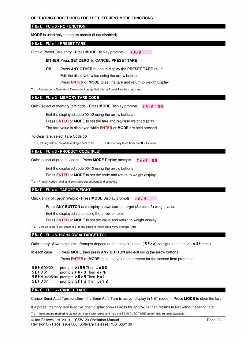
OPERATING PROCEDURES FOR THE DIFFERENT MODE FUNCTIONS
FUNC FUNC FUNC FUNC FU = 0 - NO FUNCTION MODE is used only to access menus (if not disabled)
FUNC FUNC FUNC FUNC FU = 1 - PRESET TARE Simple Preset Tare entry - Press MODE Display prompts
EITHER Press SET ZERO to CANCEL PRESET TARE OR Press ANY OTHER button to display the PRESET TARE value
Edit the displayed value using the arrow buttons
Press ENTER or MODE to set the tare and return to weight display Tip - Remember a Semi Auto Tare cannot be applied after a Preset Tare has been set
FUNC FUNC FUNC FUNC FU = 2 - MEMORY TARE CODE Quick select of memory tare code - Press MODE Display prompts
Edit the displayed code 00-12 using the arrow buttons
Press ENTER or MODE to set the tare and return to weight display
The tare value is displayed while ENTER or MODE are held pressed
To clear tare, select Tare Code 00
Tip - Holding side arrow while editing clears to 00 -Edit memory tares from the useruseruseruser menu
FUNC FUNC FUNC FUNC FU = 3 - PRODUCT CODE (PLU) Quick select of product codes - Press MODE Display prompts
Edit the displayed code 00-12 using the arrow buttons
Press ENTER or MODE to set the code and return to weight display
Tip - Product codes recall and set stored descriptions and setpoints
FUNC FUNC FUNC FUNC FU = 4 - TARGET WEIGHT Quick entry of Target Weight - Press MODE Display prompts
Press ANY BUTTON and display shows current target (Setpoint 3) weight value
Edit the displayed value using the arrow buttons
Press ENTER or MODE to set the value and return to weight display
Tip - Can be used to set 'setpoint 3' in any setpoint mode but always prompts 'tArg'
FUNC FUNC FUNC FUNC FU = 5- HIGH/LOW or TARGET/TOL
Quick entry of two setpoints - Prompts depend on the setpoint mode (SETDSETDSETDSETD) configured in the In_oUtIn_oUtIn_oUtIn_oUt menu. In each case Press MODE then press ANY BUTTON and edit using the arrow buttons
Press ENTER or MODE to set the value then repeat for the second item prompted
SETDSETDSETDSETD 00/02 prompts HIGHHIGHHIGHHIGH Then LOUULOUULOUULOUU
SETDSETDSETDSETD 01 prompts TARGTARGTARGTARG Then DRIBDRIBDRIBDRIB
SETDSETDSETDSETD 04/05/06 prompts TARGTARGTARGTARG Then TOLTOLTOLTOL
SETDSETDSETDSETD 07 prompts SPT3SPT3SPT3SPT3 Then SPT2SPT2SPT2SPT2
FUNC FUNC FUNC FUNC FU = 6 - CANCEL TARE Cancel Semi-Auto Tare function - If a Semi-Auto Tare is active (display in NET mode) – Press MODE to clear the tare. If a preset/memory tare is active, then display shows Gross for approx 5s then returns to Net without altering tare.
Tip - the standard method to cancel semi auto tare (press and hold the SEMI AUTO TARE button) also remains available.

Ian Fellows Ltd. 2013 – CSW-20 Operation Manual Page 24 Revision B - Page Issue 008 Software Release PO6_036/136
Sure?Sure?Sure?Sure?
FUNC FUNC FUNC FUNC FU = 7- PRINT & CLEAR TOTAL Total Print and Clear function - Press MODE Display prompts If ENTER is pressed - the system performs total print for the current Product Code and resets the total. If ANY OTHER button pressed, or no button within 5s, returns to weight display without printing or clearing the total.
FUNC FUNC FUNC FUNC FU = 8 - DISPLAY TOGGLE NET/GROSS MODE toggles display between NET and GROSS display - Status LEDs identify if display is net or gross - Tare is retained while gross displayed, system continues to monitor net for printing and outputs - Any functions performed while displaying gross will return system to net display
FUNC FUNC FUNC FUNC FU = 9 - DISPLAY TOGGLE NET/TARE/GROSS MODE toggles display between NET - TARE - GROSS displays - Status LEDs identify if display is net or gross (tare = all LEDs off) - Tare is the internally stored semi auto tare value (rounded) - Tare is retained while gross displayed, system continues to monitor net for printing and outputs - Any functions performed will return system to net display Tip - this setting must be used for peak weight mode, in this case it toggles NET/TARE/GROSS/MAX/MIN (Just GROSS/MAX/MIN if no tare active) OTHER SPECIAL USES OF MODE BUTTON PARTS COUNTING - If the system is placed in 'COUNT' mode then the MODE button operates always for count
functions as described, regardless of which FUNCFUNCFUNCFUNC FU is set.
PEAK - For PEAK weight detection (CONFIG PEAKCONFIG PEAKCONFIG PEAKCONFIG PEAK [MA] = 1) then FUNC FUNC FUNC FUNC [FU] must be set to 9) WARNING – Operation of MODE functions (as with menus) will temporarily inhibit other weighing and communication functions. Any analogue output will assume its error state.

Ian Fellows Ltd. 2013 – CSW-20 Operation Manual Page 25 Revision B - Page Issue 008 Software Release PO6_036/136
4. ADVANCED FEATURES
4.1 Using Tares (Net Weighing) There are two types of tare function. ‘Semi-Automatic Tare’ - tares the current weight to zero by simply pressing the SEMI AUTO TARE front panel button. ‘Preset/Memory Tares - apply an entered value as the tare weight. Provided no Preset Tare is active, and the weight is stable, the SEMI-AUTO TARE button will tare the display to show NET ZERO. Additive weighing can be performed by repeated load and tare operations. To cancel tare, PRESS & HOLD the SEMI-AUTO TARE key, for 1 second. The display returns to GROSS mode. See previous section for configuration of additional facilities. For example the MODE button can be used as a CANCEL TARE function or perhaps to toggle the display between GROSS/NET modes without cancelling (losing) the tare. Note - Preset tares may be selected ‘on top’ of an existing semi-auto tare, but a semi-auto tare cannot be selected (or cancelled) once a Preset tare is in operation. Pressing SEMI-AUTO TARE while a preset tare is active will temporarily show GROSS weight then revert to NET display.
PRESET TARES A PRESET TARE can be set either by simple entry of the value required or by recalling one of 12 previously stored memory tares.
PROGRAMMING MEMORY TARES - USEr___ tArEUSEr___ tArEUSEr___ tArEUSEr___ tArE
There are 12 Preset Tare weight registers -tArE 01tArE 01tArE 01tArE 01----12 12 12 12 (tArE 00tArE 00tArE 00tArE 00 = no preset tare set). Once these registers have values stored in them, a tare can be applied by selecting the tare code required.
In the USER___USER___USER___USER___ MENU, select tArEtArEtArEtArE ~ the currently selected ‘register address’ is shown. Press MODE and use arrow keys to select a tare code between 01 and 12 then press ENTER The stored tare for this code is now displayed (NET and GROSS LEDs flash). At this stage, you may browse other tare codes using keys To modify the value of any tare, press MODE and edit using the arrow keys then press ENTER Exit with ENTER or
The last selected code is set on return to weight display mode. If no Preset Tare is required, set tArE 00tArE 00tArE 00tArE 00 OPERATION
Whilst the USERUSERUSERUSER menu can be used to select and adjust preset tares, it is much simpler to configure the MODE button to provide the preferred operation. The MODE button can be arranged as a function to permit selection of tare codes or to allow simple entry of a Preset tare weight as required.
Simple Preset Tare entry FUNC FUNC FUNC FUNC FU = 1
Memory tare code entry FUNC FUNC FUNC FUNC FU = 2
See MODE FUNCTIONS, section 3.9 for operating instructions OTHER TARE OPERATIONS
Automatic Tare Cancellation The Auto Zero Setting option, Config ZsetConfig ZsetConfig ZsetConfig Zset = 1, will automatically cancel any tare if the display returns to a negative value within zero-setting range and remains stable for 5 seconds –after tares are cancelled, an automatic SET ZERO function is attempted. Remote Tare Functions Semi Auto and Cancel Tare can be applied using remote inputs, see later in this section. Autotare On Start An autotare can be applied at the start of a filling sequence – See section 4.5

Ian Fellows Ltd. 2013 – CSW-20 Operation Manual Page 26 Revision B - Page Issue 008 Software Release PO6_036/136
4.2 Setpoint Operations - overview Several modes of operation can exploit the use of setpoints and the control outputs for checkweighing, level control and filling operations.
The mode is set by the parameter SEtdSEtdSEtdSEtd in the In_Out_In_Out_In_Out_In_Out_ MENU.
SetdSetdSetdSetd = 07 (Default) provides 3 simple trip outputs.
SetdSetdSetdSetd = 03 permits control of outputs only via serial commands (O11/O10, O21/O20, O31/O30)
SetdSetdSetdSetd = 00/02/04/05/06 provide various arrangements for Pass/Fail or Low/Pass/High checkweighing
SetdSetdSetdSetd = 01 provides a sophisticated filling program
Setpoint values are defined by parameters in the bAtCH__bAtCH__bAtCH__bAtCH__ MENU.
The setpoint prompts alter according to the setpoint mode (SEtdSEtdSEtdSEtd ) in operation.
Setpoint Mode 'Setpoint 1' 'Setpoint 2' 'Setpoint 3'
Setd 03Setd 03Setd 03Setd 03, 07070707 Spt1Spt1Spt1Spt1 Spt2Spt2Spt2Spt2 Spt3Spt3Spt3Spt3
Setd 00Setd 00Setd 00Setd 00, 02020202 Spt1Spt1Spt1Spt1 LouuLouuLouuLouu HighHighHighHigh
Setd 04Setd 04Setd 04Setd 04, 05050505, 06060606 Spt1Spt1Spt1Spt1 toltoltoltol targtargtargtarg
Setd 01Setd 01Setd 01Setd 01 Spt1Spt1Spt1Spt1 DribDribDribDrib targtargtargtarg Sets of values can be stored and recalled for each of the 12 PRODUCT CODES.
Select CodECodECodECodE parameter and set PRODUCT CODE (01 - 12) Select and set each setpoint parameter in turn The MODE button can be arranged as a function to permit easy selection of Product Code or direct entry of some of the setpoints – see section 3.9 Versions up to PO6.029/129 prompted many of the setpoints for entry to include the extended (x10 resolution) digit, regardless of whether the display was being operated in x10 mode. From PO6.030/130, setpoints are prompted in the current display mode - ie. usually without the extended digit. It is possible to configure operation as before by changing the SETD parameter from 0x to 1x.
4.3 Simple Trip Mode - Setpoint Mode 07 (Default)
IN_OUT SEtdIN_OUT SEtdIN_OUT SEtdIN_OUT SEtd 07070707 -- Simple 3 trip mode --- (Default) In this mode, each output independently relates to its individual setpoint
If Weight > SPt3SPt3SPt3SPt3 then OP3 is ON If Weight < SPSPSPSPt3t3t3t3 then OP3 is OFF
If Weight > SPt2SPt2SPt2SPt2 then OP2 is ON If Weight < SPt2SPt2SPt2SPt2 then OP2 is OFF
If Weight > SPt1SPt1SPt1SPt1 then OP1 is ON If Weight < SPt1SPt1SPt1SPt1 then OP1 is OFF
4.4 Checkweighing Modes - Setpoint Mode 00, 02, 04, 05, 06
Status characters L/P/H or F/P/F can be shown in the left display digit, if enabled by parameter IN_OUT STATIN_OUT STATIN_OUT STATIN_OUT STAT = 1 The following tables illustrate the output states for the various checkweighing modes.
The states shown are the default operation. Changing parameter IN_OUT O3ENIN_OUT O3ENIN_OUT O3ENIN_OUT O3EN (default =1) to 0 modifies the output states to mimic the operation of LUCID weight indicators using only two outputs. Normal operation might be
further altered by use of the OPALOPALOPALOPAL parameter, see later.
SEtdSEtdSEtdSEtd 00000000 --Pass/Fail checkweighing - HighHighHighHigh andLouuLouuLouuLouu limits are individually set as required
Weight OP1 OP2 OP3 Status
Byte Display Status
Meaning
ON OFF Not Used F FFFF Out of Tolerance/Fail
OFF ON Not Used P PPPP In Tolerance/Pass
ON OFF Not Used F FFFF Out of Tolerance/Fail
=/> HighHighHighHigh
> LouuLouuLouuLouu
> Spt1Spt1Spt1Spt1
Zero
OFF OFF Not Used Z Near Zero
Ian Fellows Ltd. 2013 – CSW-20 Operation Manual Page 27 Revision B - Page Issue 008 Software Release PO6_036/136
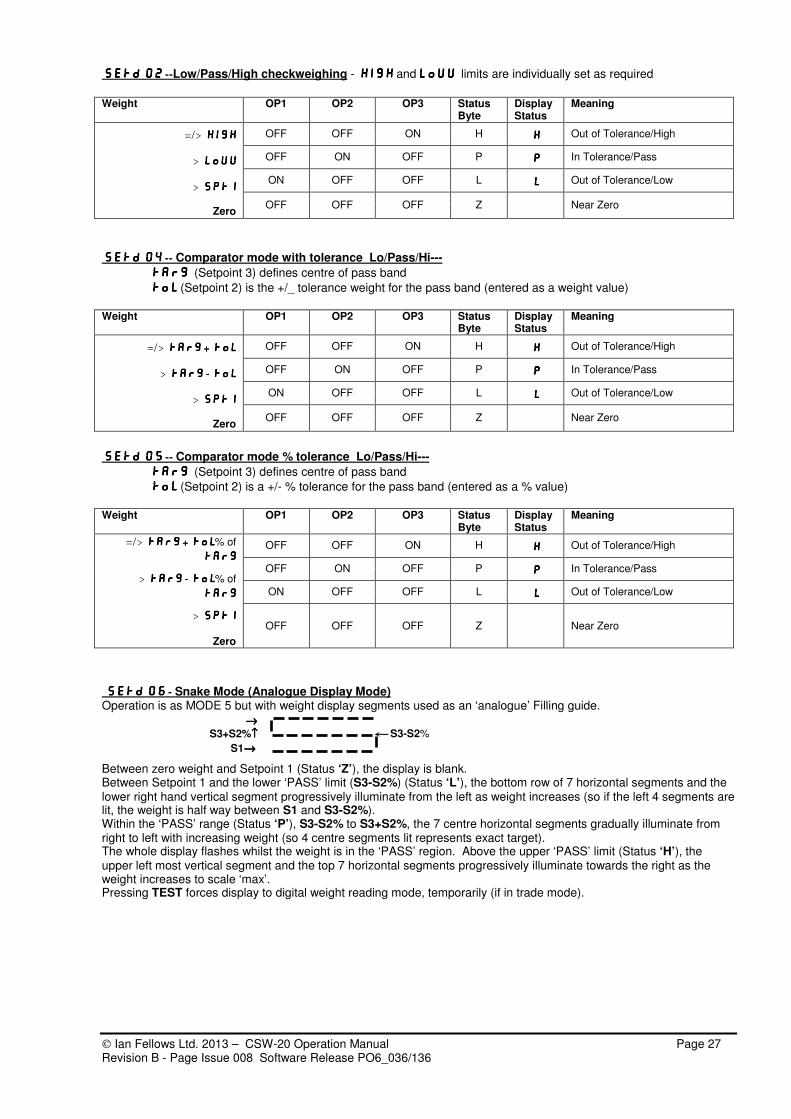
SEtdSEtdSEtdSEtd 02020202 --Low/Pass/High checkweighing - HighHighHighHigh andLouuLouuLouuLouu limits are individually set as required
Weight OP1 OP2 OP3 Status
Byte Display Status
Meaning
OFF OFF ON H HHHH Out of Tolerance/High
OFF ON OFF P PPPP In Tolerance/Pass
ON OFF OFF L LLLL Out of Tolerance/Low
=/> HighHighHighHigh
> LouuLouuLouuLouu
> Spt1Spt1Spt1Spt1
Zero
OFF OFF OFF Z Near Zero
SEtdSEtdSEtdSEtd 04040404 -- Comparator mode with tolerance Lo/Pass/Hi---
targtargtargtarg (Setpoint 3) defines centre of pass band
toltoltoltol (Setpoint 2) is the +/_ tolerance weight for the pass band (entered as a weight value)
Weight OP1 OP2 OP3 Status
Byte Display Status
Meaning
OFF OFF ON H HHHH Out of Tolerance/High
OFF ON OFF P PPPP In Tolerance/Pass
ON OFF OFF L LLLL Out of Tolerance/Low
=/> TargTargTargTarg + + + + TolTolTolTol
> TargTargTargTarg ---- TolTolTolTol
> Spt1Spt1Spt1Spt1
Zero
OFF OFF OFF Z Near Zero
SEtdSEtdSEtdSEtd 05050505 -- Comparator mode % tolerance Lo/Pass/Hi---
targtargtargtarg (Setpoint 3) defines centre of pass band
toltoltoltol (Setpoint 2) is a +/- % tolerance for the pass band (entered as a % value)
Weight OP1 OP2 OP3 Status
Byte Display Status
Meaning
OFF OFF ON H HHHH Out of Tolerance/High
OFF ON OFF P PPPP In Tolerance/Pass
ON OFF OFF L LLLL Out of Tolerance/Low
=/> TargTargTargTarg + + + + TolTolTolTol% of
targtargtargtarg
> TargTargTargTarg ---- TolTolTolTol% of
targtargtargtarg
> Spt1Spt1Spt1Spt1
Zero
OFF OFF OFF Z Near Zero
SEtdSEtdSEtdSEtd 06060606 - Snake Mode (Analogue Display Mode) Operation is as MODE 5 but with weight display segments used as an ‘analogue’ Filling guide.
→→→→ S3+S2%↑↑↑↑ S3-S2% S1→→→→
Between zero weight and Setpoint 1 (Status ‘Z’), the display is blank. Between Setpoint 1 and the lower ‘PASS’ limit (S3-S2%) (Status ‘L’), the bottom row of 7 horizontal segments and the lower right hand vertical segment progressively illuminate from the left as weight increases (so if the left 4 segments are lit, the weight is half way between S1 and S3-S2%). Within the ‘PASS’ range (Status ‘P’), S3-S2% to S3+S2%, the 7 centre horizontal segments gradually illuminate from right to left with increasing weight (so 4 centre segments lit represents exact target). The whole display flashes whilst the weight is in the ‘PASS’ region. Above the upper ‘PASS’ limit (Status ‘H’), the upper left most vertical segment and the top 7 horizontal segments progressively illuminate towards the right as the weight increases to scale ‘max’. Pressing TEST forces display to digital weight reading mode, temporarily (if in trade mode).
Ian Fellows Ltd. 2013 – CSW-20 Operation Manual Page 28 Revision B - Page Issue 008 Software Release PO6_036/136
4.5 Batchweighing - Setpoint Mode 01
In_oUt In_oUt In_oUt In_oUt SESESESETDTDTDTD 01 01 01 01 ~ Batching Control
SEtdSEtdSEtdSEtd 01010101 is selected in the In_oUt_In_oUt_In_oUt_In_oUt_ MENU. Setpoints are defined in the bAtCH_bAtCH_bAtCH_bAtCH_ MENU as is the InFtInFtInFtInFt
and the PtoLPtoLPtoLPtoL Print Tolerance parameter which determines the acceptable limits for printing about the target. These five parameters are set individually for each of the 12 PRODUCT CODES. START & STOP FUNCTIONS Batch control will in most case require use of the remote inputs configured as Start (+autotare) and Stop commands.
These remote Start and Stop functions are configured by setting IIIIN_Out IPALN_Out IPALN_Out IPALN_Out IPAL =01 This allocates I/P1 as START and I/P2 as STOP(Abort)
See section 4.6 for alternative IPALIPALIPALIPAL settings
Basic Configuration Parameters - IN_OutIN_OutIN_OutIN_Out menu
SetdSetdSetdSetd =01 batching mode
IPALIPALIPALIPAL =01 I/P1 = Start, I/P2 = Stop
AtstAtstAtstAtst =1 for Autotare on start if required
AinFAinFAinFAinF =01 for Automatic In-Flight-Compensation if required. These are the basic settings required for simple 2 speed fill control. After setting Target/Dribble/Inflight and Setpoint 1 in the batch menu, the system is ready to run. Additional facilities can then be applied as required. By default Output 1 = Bulk (fast) feed Output 2 = Dribble (slow ) feed Output 3 can be configured using the OPAL parameter (Sec 4.7) and might typically be used as a complete output
Batching Parameters - BatchBatchBatchBatch menu
CodECodECodECodE selects Material PRODUCT CODE (01 - 12). The following are stored separately for each code.
tArgtArgtArgtArg (Setpoint 3) desired Final TARGET Weight.
drIbdrIbdrIbdrIb (Setpoint 2) the DRIBBLE (fine) FEED Quantity (amount before target)
SPt1SPt1SPt1SPt1 (Setpoint 1) LOWER ENABLE LIMIT - dispalyed weight must be within this band about zero to permit start of batch. Can be used for auto start of next fill when the weight drops below this figure & start i/p active.
InFtInFtInFtInFt (In-flight Compensation) the ‘IN-FLIGHT’ WEIGHT VALUE.
PtoPtoPtoPtoLLLL (Print Tolerance) limits for printing (Requires use of Pr_CFG TOLP AutoPr_CFG TOLP AutoPr_CFG TOLP AutoPr_CFG TOLP Auto etc - see later)
JogtJogtJogtJogt (Jog Time) On Period for Jog mS (Requires use of Pr_CFG TOLP AutoPr_CFG TOLP AutoPr_CFG TOLP AutoPr_CFG TOLP Auto etc - see later)
ofilofilofilofil Overfill offset for cut off and inflight calculations – (range 0-255e)
SamPSamPSamPSamP (Sample final achieved weight every nn) For all other batches, skips checks/print etc at batch end.
IMPORTANT The ‘STOP’ Input is configured to be ‘FAILSAFE’; it MUST be present before the ‘START’ signal will be
recognised. ie I/P2 must be arranged to be normally ON for batch to run.
The ‘STOP’ Input should not be relied on as a 'SAFETY STOP’ such isolation should be provided elsewhere

Ian Fellows Ltd. 2013 – CSW-20 Operation Manual Page 29 Revision B - Page Issue 008 Software Release PO6_036/136
Batch with Printing The details below outline the key parameters governing use of printing for batching operations.
bAtCH_bAtCH_bAtCH_bAtCH_ Menu
PtoLPtoLPtoLPtoL Determines pass/fail criteria for batching. Sets the limits for Autoprinting in conjunction with toLPtoLPtoLPtoLP
and poStpoStpoStpoSt. Can be set for up to 14 batch product codes.
SampSampSampSamp Enables some weighments to be immediately discharged on cut-off without tolerance checks, printing
or auto inflight compensation. The samp samp samp samp number, 1 to 99, is the interval after which a check is initiated. Values of 00 & 01 mean checks are made for all weighments.
Pr_CFg_Pr_CFg_Pr_CFg_Pr_CFg_ Menu
ToLPToLPToLPToLP Print In Tolerance parameter may either be ON (1) or OFF (0). If OFF tolerance checking will not be
done, even if PtoLPtoLPtoLPtoL is active, if ON then operation depends on the Setpoint Mode selected. If
Setd 01 Setd 01 Setd 01 Setd 01 or 07 07 07 07 then tolerance check will be +/- the PtoLPtoLPtoLPtoL value of the tArg tArg tArg tArg
(Setpoint 3) i.e the 'Ready to Print' flag will be set when in these bounds (Printing will occur when other conditions all correct).
If Setd 00 Setd 00 Setd 00 Setd 00, 02020202, 04040404, 05050505 or 06 06 06 06 then the 'Ready to Print' flag will be set when the weight is
within the "PASS" Band as set by the three setpoints and this will over-ride anyptoLptoLptoLptoL value that may be set.
PoStPoStPoStPoSt Print in Positive Tolerance parameter may also either be ON (1) or OFF(0) and enables positive only
tolerance checking. If OFF then tolerance checking will be exactly as defined in toLPtoLPtoLPtoLP. If ON then
the tolerance check will be + PPPPtoLtoLtoLtoL of targtargtargtarg . This restricts the scope of PtoLPtoLPtoLPtoL such that the
'Ready to Print' flag will only be set when within the positive tolerance. Note that tolptolptolptolp must be ON for this to be effective.
Auto 0Auto 0Auto 0Auto 0 Autoprint disabled, print must be manually requested.
AutAutAutAutoooo 1111 Autoprint enabled, a printout will occur as soon as conditions for printing are met (see below and 5.5). With default settings, this would mean a print occurring at the first stable weight above ‘Min’ but prohibited until Batch programme is run.
In_In_In_In_oUt_oUt_oUt_oUt_ Menu
oPAL oPAL oPAL oPAL Used to modify O/P functionality see Section 4.7. Discharge and Print Parameters
In_oUt_In_oUt_In_oUt_In_oUt_
DSCHDSCHDSCHDSCH The Bulk Output can be allocated as a Discharge Output. The Discharge mode parameter can be used to force the discharge at the end of the 'batching' program regardless of achieved weight. May either be ON (1) or OFF (0). If OFF, the default setting, then at the end of the 'batching' program
the MSD will display an E E E E indicating the end. No discharge will occur. If ON then at the end of the program, Output 1 (Bulk O/P) will turn ON again indicating a discharge is required. This Output will remain On until the weight drops below the value entered to setpoint one.
DSPrDSPrDSPrDSPr Discharge on Print parameter can be used to inhibit the discharge if a successful print has not occured. May either be ON (1) or OFF (0) and if OFF, the default value, then discharge will be
dependent solely on the state of dSCHdSCHdSCHdSCH as above. If ON then discharge will only occur after a successful print function has completed. If not automatic, or out of tolerance, then manual
adjustments can be made prior to printing and then discharging. Note that dschdschdschdsch must be ON for this parameter to be effective.
Calm Timer and Jogging.
In_oUt_In_oUt_In_oUt_In_oUt_ CALmCALmCALmCALm The Batch Calm Timer may be set to run at the end of a batch to allow filling to complete. Can be set
from 00 (default) to 99 and determines the length of time the system waits in 0.1 second increments. I.e. 40 = 4 seconds and this will be the interval after the dribble output has turned OFF before the weight will be checked and the batch "program" can proceed. Also sets the interval (plus motion criteria) between jogs, see next.
JogtJogtJogtJogt Determines whether jogging is active (01 to 5119) or turned OFF (00 the default value). If the batch
weight achieved is below the minimum tolerance set by ptol/tolp/post, and jogging is active, then up to three jogs may occur to bring the weight within required limits. The value entered will be used to determine the JOG ON interval in milliseconds. The value entered will round down to the next 20mS i.e. an entry of 5119 will round down to 5100mS; an entry of 21-39 will give a jog ON period of 20mS.

Ian Fellows Ltd. 2013 – CSW-20 Operation Manual Page 30 Revision B - Page Issue 008 Software Release PO6_036/136
Typical Batching Cycle
START SIGNAL (Note: stop input is ‘failsafe’, hence must be energised). Provided that the displayed weight is stable, Motion Lamp is OFF, and the displayed weight is below the value
entered to the parameter spt1spt1spt1spt1 then: -
• Either, Signal to ip1; which must be selected for “Start” - IPAL0IPAL0IPAL0IPAL0x
• AUTO-TARE TO NET ZERO adjustment will occur if Atst1Atst1Atst1Atst1
• or, Set Strt1Strt1Strt1Strt1 in bAtCH__bAtCH__bAtCH__bAtCH__ menu,
• or send ‘ST1’ command from serial port.
• In above two cases ; Feed starts immediately if weight is less than the high limit Note: - Start will continue to attempt to activate as long as the start signal is active, i.e. would wait for a stable condition and then start. Signal should be removed once a valid start has occurred.
BULK FEED Output 1 (Bulk) and Output 2 (Dribble) operate (bbbb status character)
• Output remains on until the the weight exceeds the bulk feed cut-off point~ • BULK FEED CUT-OFF = TARGET - DRIBBLE - INFLIGHT.
At this point Output 1 releases, leaving Output 2 to complete dribble feed. O/P 1 is NOT latched and would turn ON again if the weight dropped back below this Cut-Off Value.
DRIBBLE FEED Output 2 Remains operated (dddd status character)
• Output 2 remains on until final cut-off point~
• FINAL CUT-OFF = TARGET - INFLIGHT . At this point Output 2 Releases. O/P's 1 & 2 now latch OFF pending any further conditions.
CUT-OFF – occurs (display MSD blank)
If a Non-Sampled weighment go to Batch Complete below.
If CALmCALmCALmCALm timeout is awaited bUSYbUSYbUSYbUSY displays.
• If Automatic In-flight Compensation Adjustment is selected AInFAInFAInFAInF 1111 and a stable weight within +/-12.5% of the
capacity is detected, an adjustment of the currently selected InFtInFtInFtInFt value by 25% of any error is carried out subject to total restrictions.
• If jogtjogtjogtjogt is active and final weight is below the minimum tolerance set then the system may jog the product three times to try to achieve an in-tolerance weight. The System will turn ON the Dribble Feed Output 2 for a period as
set to this parameter and then OFF for the period entered in CALmCALmCALmCALm plus the period required for weight stabilisation and weight check.
• If AUTOPRINT mode is NOT selected (Auto 0Auto 0Auto 0Auto 0 in Pr_CFg_Pr_CFg_Pr_CFg_Pr_CFg_), the cycle stops until the operator removes/discharges the batch. A printout may be obtained prior to discharge by pressing PRINT or requesting
‘PR’ via the Serial Interface (EEEE status character)
• If AUTOPRINT mode IS selected, If stable weight is within tolerance an auto-print of the selected data will occur.
Start Command
OP1 ‘ON’
OP2 ‘ON’
‘Dribble’ ‘Bulk’ SPt 1
Stable
‘Discharge’
‘calm’ time and waiting stability
OP1 ‘ON’ (if selected)
Time
tArg + oFIL – InFt - DrbL
tArg + oFIL – InFt)
(tArg + oFIL) (Target)
Weight
If non-sampled OR Calm AND Jog AND Autoprint
NOT selected, go straight to ‘Discharge’
If ‘Auto Tare on Start’ enabled and I/P 1 (start) is on,
will start looking for stability here

Ian Fellows Ltd. 2013 – CSW-20 Operation Manual Page 31 Revision B - Page Issue 008 Software Release PO6_036/136
BATCH COMPLETE (EEEE status character) Subject to Discharge conditions, Output 1 OPERATES to denote DISCHARGE. This special discharge state may be used to initiate DISCHARGE, or operator controls load removal directly. Batch Complete status (see 4.7) could be allocated to O/ps 1 or 2, if single feed, or O/p 3 if available.
If START COMMAND from remote Input 1 is still valid, the next cycle starts as soon as weight stabilises below
Setpoint 1. Otherwise, a new Start Command is awaited before re-commencing the cycle. Note If not required, it is preferable to disable the analogue output when batchweighing in order to achieve best ‘cutoff’
accuracy in high-speed applications (AnEnAnEnAnEnAnEn 0000 in Eng_CFgEng_CFgEng_CFgEng_CFg). Default is disabled. SEMI-AUTO TARE and PRINT are disabled during fill.
4.6 Remote Operation (Control I/P assignment) The two Control Inputs can be configured to act as Start/Stop Batch signals or as remote alternatives for the front panel buttons (see 4.3 for typical wiring).
The IPALIPALIPALIPAL parameter in In_oUt_In_oUt_In_oUt_In_oUt_ is a two-digit parameter; the first selects input 1 action; the second (least significant) selects input 2 action. ‘IPAL . <i/p1> . . . . <i/p2>’ 0 = start batch 0 = start batch 1 = hold batch (after fill) 1 = stop batch 2 = acquire tare (default) 2 = acquire tare 3 = toggle tare (acquire if in Gross, 3 = cancel tare (default) 4 = print cancel if in Net) 4 = print 5 = set zero 5 = set zero 6 = display gross 6 = display gross 7 = send/display totalised net wt.
+ 7 = send/display totalised net wt.
+
8 = print/clear totalised wt.+ 8 = print/clear totalised wt.
+
9 = print, don’t clear, totalised wt.+ 9 = re-configure i/p2 as output 3*
+ operate on currently selected PRODUCT CODE total. 8/9 clear/print all if CODE = 99.
* requires i/p2 to be factory (hardware) configured as an output. A second indicator may be used as a ‘Remote’ Display/Keyboard for the ‘Local’ indicator. They are interconnected via
their Serial Interface ports and the rmdSrmdSrmdSrmdS parameter in SErIAL_SErIAL_SErIAL_SErIAL_ is set in each unit according to the list in Section 5.2.
4.7 Control O/P and Printout Assignment The oPALoPALoPALoPAL parameter in In_oUt_In_oUt_In_oUt_In_oUt_ consists of six hex digits which can modify the operation of each output as below:
Digit No: 1 2 3 4 5 6 7
OUTPUT 1 OUTPUT 2 OUTPUT 3 (only if fitted)
Not Used – see note
Comparator Mode
OUTPUT 1 Comparator Mode*
Status Mode
Comparator Mode*
Status Mode
Note: Digit 1 is unused – from NO6_00F is automatically set by the software and used as a check digit.
* These digits unused except in Setpoint Mode SEtdSEtdSEtdSEtd 07070707. Outputs operate as described in Setpoint Mode descriptions (see 4.3 and 4.4), but may be customised using these digits. Leave as all zeroes unless special function required. In such cases, read the following carefully before modifying Digits 2-7.
Digit 2 Modifies how outputs operate in Setpoint Modes other than ‘07’ 0 (Default) Setpoint weight value based on Net Weight. Setpoint values are positive of this zero, and
output operation is ‘instantaneous’ (stability is not awaited). 1 Setpoint weight values based on Gross Weight (‘zero’ is always true zero weight). Only valid for
Setpoint Modes 00, 02, 03 and 07. 2 Setpoints operate when Negative of indicated zero instead of positive (for weighing out). 4 Setpoints operate when Positive or Negative (i.e. on the modulus of weight). 8 Must await stability (no-motion) before outputs operate.
The values above may be summed to give a combination of ‘modifications’. E.G. 'OPAL 9xxxxx’ (i.e. 8+1) would delay output operation until a stable gross weight at or above the particular setpoint was reached. ‘OPAL Cxxxxx’ (8+4); output operates when no motion at or beyond setpoint, positive or negative of NET zero.

Ian Fellows Ltd. 2013 – CSW-20 Operation Manual Page 32 Revision B - Page Issue 008 Software Release PO6_036/136
Digits 2, 4, 6 Modify how outputs operate in Setpoint Mode ‘07’ In this mode, each output has it’s own ‘definition’ digit, each as described above, rather than all being forced to the same function as defined by digit 2. Thus, one output might be modified to operate only on no-motion, for example.
Output 3, if fitted (factory option), is only available for Setpoint Mode in Mode 07. In other modes it may therefore
be used to indicate a particular Status condition; according to the table below.
Digits 3, 5, 7 If not at zero (default), the Output (1, 2, 3) corresponding to the digit (3, 5, 7) is forced into a Status Mode (regardless of Setpoint Mode selected) and operates on the status conditions as listed below. Thus a digit other than zero overrides the normal Comparator operation as described in Setpoint Modes for the particular output.
0 (Default) Output operates in normal Setpoint Mode (as 4.3 / 4.4 and modified as above) 1 Output operates on Net mode (follows NET indicator). 2 Output operates on Motion (follows MOTION indicator). 3 Output releases (i.e. failsafe) on Alarm condition*. 4 Output operates when Negative and in Net mode. 5 Output operates on Negative Gross. 6 Output releases (i.e. failsafe) when weight Out of Range. 7 Output operates on Gross Zero (follows ZERO indicator). 8 Output operates on Net Zero. 9 Output operates on Gross mode (follows GROSS indicator).
A Output operates when ‘Printed’ Flag set (i.e. after successful print)+. C Output operates at Batch Complete. D Output operates by Serial Commands Only.
∗ Alarm condition is any non-weighing mode; such as parameter entry mode, calibration, out of range, or any detected error condition.
+ If ‘A’ is selected, the appropriate output is reset when a new print is allowed (after return to zero or sufficient weight change; as programmed).
Examples of Output Allocation Parameter
oPALoPALoPALoPAL 00 00 0C OP’s 1 and 2 operate as normal. OP3 operates as ‘Batch Complete’ signal (SETD 01 only). 00 00 0A OP’s 1 and 2 operate as normal. OP3 operates when print successful. 10 08 20 Using SETD 07, this arrangement might be used for filling and discharging a vessel
OP 1 monitors Gross weight (ie contents high level) O/P2 net zero status (confirms successful tare to zero) O/P3 monitors negative net (amount removed after tare)
20 00 0C Using SETD 01
OPs 1 and 2 operate negative for ‘weighing out’. OP3 is batch complete
80 00 00 Using SETD 00, 02, 04, 05, 06 - OPs operate only when stable. Hence the appropriate low/pass/high signal will not be given until weight stabilises.
00 00 04 OP 3 comes on when weight is negative and net.
Such an output might be wired to (say) input 2 to automatically CANCEL TARE when load removed.

Ian Fellows Ltd. 2013 – CSW-20 Operation Manual Page 33 Revision B - Page Issue 008 Software Release PO6_036/136
4.8 Part Counting Several methods of simplified Part Counting are described below where the MODE key operates as a Sample button.
Count mode has to be enabled with CnEn CnEn CnEn CnEn in CoUntCoUntCoUntCoUnt__ menu set ON (1). Display will show live count with flashing
CCCC in leftmost digit position. (Count mode over-rides any MODE Function set with FUNCFUNCFUNCFUNC parameter) Sample Weighing With the weighpan empty, ensure the ‘ZERO’ light is on ~ press SET ZERO if not. Add the required sample number (1-99) to the weighpan ~ press MODE
Display will show AddAddAddAdd nnnnnnnn The sample size on the pan can now be entered as follows The when pressed increments the units, 1, 2, 3, 4, 5, 6, 7, 8, 9, 0 but does NOT carry over. The key increments the tens similarly, 10, 20, 30 etc. E.g. to enter 32 press Press ENTER . A new part weight will be calculated; part weight must be greater than e/10 otherwise the display
will change to show AddAddAddAdd --------
clears sample showing AddAddAddAdd 00000000 a second press will toggle the display to show AddAddAddAdd --------.
Pressing ENTER whilst displaying AAAAdddddddd 00000000 returns to weighing but leaves Count mode re-enterable.
Pressing ENTER whilst displaying ADDADDADDADD -------- uses previous part weight as sample size. Part weight is calculated and internally stored in units of e/1000
Count mode can be exited by setting the CnEnCnEnCnEnCnEn parameter to zero. Whilst in the count mode, pressing TEST will display the live weight Changing to a Different Part (or to Cancel Mode) Ensure COUNT mode is enabled as Sample Weighing above With the weighpan empty, ensure the ZERO light is on ~ press SET ZERO if not Press MODE ~ display will indicate ‘Add 10’ (or 01 - 99, as previously set) Select a new sample size, if required, as below ~ Pressing increments the ‘units’ sample number digit Pressing increments the ‘tens’ sample number digit Pressing clears both digits to zero Add the selected/requested sample number to the weighpan (none if cancelling mode) Press ENTER
Display will show live count with flashing CCCC in leftmost digit position
NOTE: Pressing ENTER with AddAddAddAdd 00000000 displayed cancels Part Count Mode Counting with known Part(s) Weight
From the CoUnt__CoUnt__CoUnt__CoUnt__ MENU, select PartPartPartPart Enter EDIT mode and key in the part(s) weight Press ENTER, ENTER, ENTER to return to live display
Display will show live count with flashing CCCC in leftmost digit position Counting with Part Weight stored against Code Each time a sample is weighed, or a part weight edited, it’s value is written into the currently active ‘PRODUCT’
CODE memory (CodE CodE CodE CodE xx). Thus up to 14 pre-set items can be counted without having to do the above sample weighment.
Select CoUnt_CoUnt_CoUnt_CoUnt_ (or USEr___USEr___USEr___USEr___) menu, Select appropriate CodECodECodECodE Press ENTER, ENTER, ENTER to return to direct part counting of the selected item. Use any of the above routines to programme alternative weight into the selected ‘CodE’ location. Preferably use 01 as a ‘scratchpad’ for general part counting, using 02 - 14 for specific products. Leave 01
selected when not using pre-set items to avoid accidental corruption. Exit COUNT mode
Press MODE then to show AddAddAddAdd 00000000 then ENTER.
Alternatively, select CnEnCnEnCnEnCnEn 00000000 from the CoUnt__CoUnt__CoUnt__CoUnt__ menu. Note: Setpoints are always relative to weight regardless of count mode.

Ian Fellows Ltd. 2013 – CSW-20 Operation Manual Page 34 Revision B - Page Issue 008 Software Release PO6_036/136
4.9 LIVELIVELIVELIVE Animal Weighing
Many animal weighing applications will be readily satisfied by simply setting a higher filter (Filter Band) parameter in
CALIBn_CALIBn_CALIBn_CALIBn_ or config_config_config_config_ Menus.
Where a print is required, optimum performance might be gained by using this LIVELIVELIVELIVE parameter in Pr_CFg_Pr_CFg_Pr_CFg_Pr_CFg_ and
setting this to ‘1’. If set this will force the Motion Time-out toUttoUttoUttoUt in ConFIg_ConFIg_ConFIg_ConFIg_ to 30 seconds. On initiating a printout,
the system will look for a stable value by progressively increasing the FILtFILtFILtFILt setting until a 'no motion' condition is
found. ToUtToUtToUtToUt is used as a time limiter - if stability is reached before it expires, a print occurs. If it expires the print command is aborted.
The FILtFILtFILtFILt returns to its original value on completion.
Note: Any calibration adjustment sets livelivelivelive to OFF = 0. livelivelivelive must be reset to ON = 1 if required.
4.10 Conversion Mode A conversion factor may be applied to the current weight value and the converted value displayed and printed. Enter
the conversion factor in FACtFACtFACtFACt in the CoUnt_CoUnt_CoUnt_CoUnt_ MENU. It may be in the range 0.1000 to 10.0000.
To enable conversion mode, select ConS 1ConS 1ConS 1ConS 1 in CoUnt__ CoUnt__ CoUnt__ CoUnt__ MENU. Conversion mode is indicated by flashing ‘U’ in display most significant digit.
Exit Conversion Mode by setting ConS 0ConS 0ConS 0ConS 0. Note: Setpoints are always relative to weight regardless of any conversion.
4.11 Analogue Output (Option) Baseboards Rev C may have an integral analogue output fitted. Rev D onward use an optional plug in module. The DAC is designed to an ultimate resolution of about 1 part in 50,000 over full range output. However, its overall performance is optimised for medium accuracy instrumentation purposes. Typical system accuracy is in the order of
0.1% full scale over 10°C temperature range.
If analogue output is fitted, EngCFg_ AnEnEngCFg_ AnEnEngCFg_ AnEnEngCFg_ AnEn must be set to ‘1’ to enable the AnALog_AnALog_AnALog_AnALog_ menu.
The output can be 4-20mA (up to 500Ω) or 0-10V by setting parameter 4444----20202020 to 1 or 0 in the AnALog_AnALog_AnALog_AnALog_ menu. Only current loop or voltage output may be selected at one time, there must be no electrical connection between the two external circuits. Current Output is recommended. If a Voltage Output is to be used consult Application Notes at www.ianfellows.co.uk Connection
The Analogue Output is calibrated using the AnALog_AnALog_AnALog_AnALog_ menu.
To calibrate Zero output, select ZAdjZAdjZAdjZAdj press MODE then use to nudge up or down whilst monitoring the output on a meter. If a large adjustment is needed, then it can be quicker
to manually edit the ZEroZEroZEroZEro parameter.
Similarly to calibrate the gain, select gadjgadjgadjgadj and nudge as above this time checking the meter for the reading required at
the CALACALACALACALA value (usually = TOP) Again large adjustments can
be made by editing the gAIngAIngAIngAIn parameter .
A ‘false’ full scale can be programmed with the CALACALACALACALA weight
value parameter. (After any change to CALACALACALACALA it is necessary
to access the main CALIBNCALIBNCALIBNCALIBN menu and then exit to ensure the new reading is stored.)
The Output can be set to correspond with NET or GROSS using the nEtnEtnEtnEt parameter.
The output can be set to increase with loss of weight with the nEgnnEgnnEgnnEgn parameter.
If flow rate mode is enabled, the output can be set to reflect flow rate by setting the raterateraterate parameter. The error condition output (eg when out of range or when menus and functions are being operated) can be forced to
the lowest or highest electrical limit depending on theErrErrErrErr parameter. Note: The output may pass beyond the normal range, before switching to an error condition.

Ian Fellows Ltd. 2013 – CSW-20 Operation Manual Page 35 Revision B - Page Issue 008 Software Release PO6_036/136
4.12 Flow Rate Display/Output A RATE display and/or output signal, in which the ‘change of weight’ against time (‘dW/dt’) is produced, may be
enabled in non-trade mode by setting r_enr_enr_enr_en in engcfg_engcfg_engcfg_engcfg_ to 1111. Output is set in calibrated weight units per second and is displayed by a single short press of the MODE key. The rate value may be output as an analogue signal if an Analogue Output Module is installed (0-10V or 4-20mA ~ see 4.11).
Select rate 1rate 1rate 1rate 1 in the analog_analog_analog_analog_ menu to enable.
Set to 0000 to disable. Note the flow rate feature computes ‘instantaneous’ flow from changes in the immediate weighing integrations. As such it is generally not useful for slow rates of flow where the change from one integration to the next is insignificant.

Ian Fellows Ltd. 2013 – CSW-20 Operation Manual Page 36 Revision B - Page Issue 008 Software Release PO6_036/136
5. SERIAL INTERFACING AND PRINTING
5.1 Serial/Printer Installation Comms Connection – See section 1.5
5.2 Serial Comms ~ SErIAL_SErIAL_SErIAL_SErIAL_ Parameter Menu The serial port is designed to connect to a host computer for remote control, production of logs and as an input for
applications requiring weight data. For Trade Approved applications a legal weight Alibi may be required – refer to Application Note – CSW-20 Flash ETR Rev2+.
In it’s simplest application, a string of status and current weight information might be transmitted (without handshake) every time the display is updated (default; every 300ms).
At a more sophisticated level there is a powerful suite of commands that enables the host to become the ‘operator interface’ without use of the indicator panel. The ‘host’ computer applications programmer must write software to ‘talk’ to CSW-20.
All of the parameters available on the CSW-20 are available via the Serial Interface. A multi-drop (network) mode is also available for multi-weigher systems (see 5.4). Serial Port Configuration
In the Serial_ Serial_ Serial_ Serial_ Menu, use the following parameters: -
bAUdbAUdbAUdbAUd Baud rate (01=19200Bd, 02=2400Bd, 03=38400, 04=4800Bd, 09=9600Bd-Default)
PrtyPrtyPrtyPrty Parity/bits (00 = 8+none (Default), 01 = 7+odd, 02 = 7+even, 09 = 8+odd, 0A = 8+even)
h232h232h232h232 (rev C) 1=RS232, 0=RS485 ; RS485 for use on Multi-drop networks.
485E485E485E485E (rev D+) 0=RS232, 1=RS485 ; RS485 for use on Multi-drop networks. Note - On some versions baud rate changes are not permanently stored until forced to store by change of additional items. If no ‘stored’ message seen, then force store by changing another parameter.
Weight Data Format control parameters
CrLF CrLF CrLF CrLF 1111 appends a line feed to a carriage return (default 1, on : Cr = CrLf).
ECHo ECHo ECHo ECHo 1111 echoes received characters (default ‘1’)(Multi-drop mode forces Echo 0 off).
nodP nodP nodP nodP 1111 removes d.p. from weight and adds as a byte after units (default ‘0’ d.p. embedded).
CHSU CHSU CHSU CHSU 1111 appends a checksum byte to data (default ‘0’ gives no checksum).
noSt noSt noSt noSt 1111 removes status bytes from weight data (default ‘0’ embeds status bytes).
LdgzLdgzLdgzLdgz (from PO6_x33)1111 spaces in weight string bytes are replaced by zeros (default ‘0’ = spaces).
StrgStrgStrgStrg 1111 sets serial string format (SG1 or O – see 5.3).
Sing Sing Sing Sing 1111 weight data transmitted on request only (default ‘0’ gives continuous output).
CtrLCtrLCtrLCtrL Allows up to 4 Hex Control Bytes to prefix the standard weight data string.
(Default CtrLCtrLCtrLCtrL = 0000 00000000 00000000 00000000 sends no prefix characters, 00 – ‘Nulls’ are ignored. The first ‘byte’ is only 1 digit long and, thus, can only be a control character 01h - 0Fh).
Serial Commands The menus at rear of manual show the serial command corresponding to each parameter. Commands must be sent terminated with CR and the indicator allowed to complete its response before sending further commands. Below are a selection of useful commands not covered by the menu system ~
WT Request Weight RA Request current Access Level PR Request print PW Send Password ie PW1, PW900 AT Acquire new semi-auto tare AZ Set zero CT Cancel semi-auto tare NT Tare Code FT Preset Tare value Changes to Tare code, command NTxx, receive response giving current value of preset tare for that code. FT cannot be set when NT=00
XG Request gross PG Last printed Gross weight XN Request net PN Last printed Net weight XT Request semi-auto tare value PM Last printed Semi Auto Tare weight ST1 Start Batch WE1 Write data to eeprom from ram ST0 Stop Batch ?* Command list dump (from PO6_x26) MO Toggle net/tare/gross weight (= MODE) SW Read internal Pushbutton (from PO6_x33) ET1 Select x10 weight mode ET0 Deselect x10 weight mode MExxxxxxx Set display to show message xxxxxxx (status indicators all flash). Send ME to clear message. To change parameters with serial commands still demands the correct access level. In most cases this will be level 1 which is gained by sending level 1 passcode PW1. As a general rule, for configuration parameters, send the command with no value to receive the current setting. Send with a valid value, at the right access level, to change the setting. Weight registers are sent with extended x10 digit (ie superfluous 0 unless displaying x10 digit) and without decimal point. Some registers are sent with a suffix ‘type’ letter (W-weight, D-decimal, H-hex etc.) These are a legacy to earlier protocols, primarily retained for compatibility and bear no great significance.

Ian Fellows Ltd. 2013 – CSW-20 Operation Manual Page 37 Revision B - Page Issue 008 Software Release PO6_036/136
5.3 Serial Interface Weight Data Format The serial interface can be set to continuously transmit (Sing 0Sing 0Sing 0Sing 0) a weight string each time the weight display is
updated (default ~300ms) or on request only (Sing 1Sing 1Sing 1Sing 1) - request command WT (Same formats apply for request gross XG, net XN and semi-auto tare XT)
There are two string formats, selected by parameter StrgStrgStrgStrg or command SG0/SG1. Each has elements that are subject to other parameter settings. The default SG0 weight string:
Multi-drop Address (if NETNETNETNET=1) Character 00-FF hex Default = 1C
Status 4 Print Status M Weight in Motion H Gross Weight > Max + 9e (over-range)
Z Centre Zero P Printed flag set G Negative interlock active (bit5/7 also set)
B Below MIN interlock active R Ready to Print/Store See Note 4
Status 3 subject to In_OutIn_OutIn_OutIn_Out Setpoint Mode
SetdSetdSetdSetd 1 SetdSetdSetdSetd 2, 4, 5, 6 B Bulk Z Near Zero D Dribble L/F Low/Fail E Discharge H/F High/Fail S Waiting Start P Pass
SetdSetdSetdSetd 03/07(default) see Note 3
Status 1 Stability S = Stable M = Motion
Status 2 Mode G = Gross, N = Net, T = Tare Weight, P = Axle Weighing versions only
Upto 4 Prefix Characters (01-FF hex) set
by CTRLCTRLCTRLCTRL parameter
Sign/Out of Range Positive and In Range - Negative O Over Range U Under Range
Weight data 6 ascii digits or 7 with decimal point = leading spaces/zeros see Note 1
c B D S G kg x 123.45
2. All shaded items are optional
1. = Space (20h) From PO6_x33
If LDGZLDGZLDGZLDGZ=1 = Zero (30h)
4. Printable Status Notes
• M (motion) takes priority until printed, P then takes priority until reset
• H will over-rule P but not M
• BIT 7 set if NET is negative(+80h); BIT 5 set if GROSS is negative(+20h) (In GROSS MODE, net = gross, thus BIT 7 & 5 are set)
• B & G appear subject to nnInnnInnnInnnIn(MW) & NEGPNEGPNEGPNEGP(NP) parameters
• When Z set, print may or may not be permitted subject to nnINnnINnnINnnIN(MW)
• When P set, printing may be permitted by PNTUPNTUPNTUPNTU(PU) parameter
3. Status 3 Notes In Setd 03/07 the state of I/O is reflected ~ Bit 7 6 5 4 3 2 1 0 State 0 0 1 o3 o2 o1 i2 i1
1 = Off or No Input
Checksum: Modulo 128-Bit sum of all preceding characters. MSB always set if 8-Bit data
If NODPNODPNODPNODP = 1 Number of Decimal Places (0-3)
Units (set by CONFIG UNITCONFIG UNITCONFIG UNITCONFIG UNIT) None, kg, lb, g, gm, t, N, klb, mV, Fl, Cn, Cv
for normal Mode, LSD in x10 Test Mode see Note 1
4. Multi-drop Address Allocation To avoid conflicts, do NOT use addresses 0ah (LF) and 0dh (CR) or other characters contained in messages and weight strings
0xh xxh xxh xxh xxh
Notes
CR carriage return (0Dh)
CR LF
LF Line Feed (0Ah)
If CRLFCRLFCRLFCRLF =1

Ian Fellows Ltd. 2013 – CSW-20 Operation Manual Page 38 Revision B - Page Issue 008 Software Release PO6_036/136
Alternative SG1 weight string If SG1 command is sent to CSW-20 via the serial port, the following weight data format is available. Can also be set by
STRG =1 in serial menu.
I/O Status Byte – Bit 0 is least significant Bit Bits 1, 0 = Input 2, 1 status (1 = ON) Bits 4, 3, 2 = Output 3, 2, 1 status (1 = ON) Bit 5 = Always Set Bit 6 = Count Mode Bit 7 = Convert Mode (8 bit data only) Both 6 + 7 = Flow rate Mode (8 bit data only)
Net Weight Data 6 ASCII Digits Padded with leading spaces, no dp
or (from PO6_x33) zeros if set by LDGZ =1 In Part Count Mode = Net Weight
Checksum: Modulo 128-Bit sum of all preceding characters. MSB always set if 8-Bit data
CR carriage return (0Dh)
Printable Status M Weight in Motion H Gross Weight > Max + 9e (over-range)
Z Centre Zero P Printed flag set G Negative interlock active (bit5/7 also set)
B Below MIN interlock active R Ready to Print/Store
Display Format Byte, Bit 0 is LSB Bits 1, 0 = Number of decimal places (0-3) Bit 2 = Motion Bit 3 = Undefined Bits 6, 5, 4 = Units code (0-7), 0 if mV, Fl, Cn, Cv Bit 7 = Always set (8 bit data only)
Gross Weight Data 6 ascii digits = leading spaces/zeros see Note 1 No decimal point In Part Count Mode = Net Count at full resolution
1234 xxh xxh R 12345 CR c
3. Printable Status Notes
• M (motion) takes priority until printed, P then takes priority until print flag reset
• H will over-rule P but not M
• BIT 7 set if NET is negative (+80H); BIT 5 set if GROSS is negative (+20H) (In GROSS MODE, net = gross, thus BIT 7 & 5 are set)
• B & G appear subject to nnInnnInnnInnnIn(MW) & NEGPNEGPNEGPNEGP(NP) parameters
• When Z set, print may or may not be permitted subject to nnINnnINnnINnnIN(MW)
• When P set, printing may be permitted by PNTUPNTUPNTUPNTU(PU) parameter
2. All shaded items are optional
1. = Space (20h) From PO6_x33
If LDGZLDGZLDGZLDGZ=1 = Zero (30h)
5. Multi-drop Address Allocation To avoid conflicts, do NOT use addresses 0ah (LF) and 0dh (CR) or other characters contained in messages and weight strings
<
Multi-drop Address (if NETNETNETNET=1) Character 00-FF hex Default = 1C
for normal Mode, LSD in x10 Test Mode see Note 1
for normal Mode, LSD in x10 Test Mode see Note 1
Notes
LF
LF Line Feed (0Ah)
If CRLFCRLFCRLFCRLF =1

Ian Fellows Ltd. 2013 – CSW-20 Operation Manual Page 39 Revision B - Page Issue 008 Software Release PO6_036/136
5.4 Multi-drop Operation (RS 485 only) A MASTER can speak to several CSW-20 over an RS485 network (all data must now be requested).
nEt nEt nEt nEt 1111 Set to force multi-drop mode (‘0’, non multi-drop is default).
SING 1SING 1SING 1SING 1 Set so weight data on request only
Addr nnAddr nnAddr nnAddr nn Sets the multi-drop address this unit responds to (00-FF(h) 2 Digit Hex.
HHHH232232232232 (rev C) Set 0 for RS485 (1 = RS232) or
485E485E485E485E (rev D+) Set 1 for RS485 (0=RS232) RS232 can be used for addressed communications, but not multidrop Note - Change to NET parameter is not permanently stored until forced to store by change of additional items. After changing NET, force store by changing another parameter confirmed by ‘stored’ message. Use not recommended below baud rate 9600. Maximum 31 SLAVES (CSW-20) and only one MASTER. SLAVES configured with addresses 00 – FF(h) (2 Digit Hex). Connections to be twisted pair and ‘daisy-chained’ (not 'star' connected). 2 Network ends to be specified and terminated. Install terminators in cable plugs at network ends.
Fit termination resistors to match the characteristic impedance of the comms cable (if unknown, fit 100Ω) externally on the cable connectors at the extreme ends of the network. Then all indicators are identical.
SLAVES (CSW-20) will always ‘listen’ unless spoken to (no unsolicited messages). SLAVES will default to ‘listen’ within 1 character time of requested response. Time-out on all operations to default 'SLAVES listen' mode is normally 1 second. All communication ‘packets’ commence with 'Address' and terminate with CR (or CR, LF). If function demands a
response with an indeterminate delay; MASTER must poll for it. To avoid possible communication conflicts, either set 'UNITS' to 0 or do not use addresses that contain unit
characters eg k, g or characters that may be in messages and weight strings and do not use 0ah (LF) or 0ch (CR) Multi-Drop Network Notes HINTS & TIPS: The most usual problem encountered whilst setting up a RS485 2-wire system is caused by two or more devices trying to ‘talk’ at the same time. The transmitter in each indicator is enabled only in response to a command/request directly addressed to it (anything else is ignored, and there are no unsolicited messages transmitted). Hence the ‘host’ PC or Controller initiates all ‘dialogue’. The only time two indicators might try to transmit simultaneously is if both have the same address (illegal) or there is a hardware fault. Try removing units until some dialogue is established. It is important that the ‘host’ disables its transmitter immediately after sending a command/request and goes to ‘listen’ mode (also, beware of a situation where the host disables it’s transmitter prematurely, truncating the transmitted message). If an external RS232 to RS485 converter is used by the ‘host’, its RTS signal is normally used to enable the transmitter. The ‘host’ programmer must generate this signal and ensure it correctly matches the transmitted message length.
Ian Fellows Ltd. 2013 – CSW-20 Operation Manual Page 40 Revision B - Page Issue 008 Software Release PO6_036/136
5.5 Printer Config. ~ Pr_CFg_Pr_CFg_Pr_CFg_Pr_CFg_ Menu These parameters set up the printer-interface configuration. (Refer also to Printer manufacturer manuals). Note: Setting Printer Baud rate to ‘00’ re-directs output to the CSW-20 serial port. Printer Port Configuration The printer port is permanently configured for 8 data bits, 1 stop bit. To use a printer with only 7 data bit setting, set the printer to receive zero parity, or no parity and 2 stop bits.
bAUdbAUdbAUdbAUd Baud rate 00=output via serial, 01=19200, 02=2400Bd, 04=4800Bd, 09=9600Bd, 10=disable (Revised at PO6.032/132) Default 02 = 2400
PrtYPrtYPrtYPrtY Printer Parity (00=none, 01=odd, 02=even). Default 00
CrLFCrLFCrLFCrLF Printer Linefeed mode (0=CR only, 1=CR+LF) Default 0
HdSHHdSHHdSHHdSH Printer Handshake (00=none, 01=ready when high, 02=ready when low) Default 01
EoLdEoLdEoLdEoLd End of line delay (00-09 x 0.1 second delay after CR) If no handshake is used, some printers may need EOL delay to allow printer time to catch up with transmission.
Printing Conditions Note: Default is 0 ‘off’ for these parameters.
NninNninNninNnin 1 Enables Printing when below Minimum weight
(Minimum = 20 divisions ‘20e’ Except See 5E ?5E ?5E ?5E ? below)
NegPNegPNegPNegP 1 Enables Printout of a Negative Net weight (e.g. Print ‘lost’ weight). -ve Gross never allowed
ChgEChgEChgEChgE 1 Enables Print on Weight Change of 20e - otherwise, weight must return to below 3e above zero before printing is re-enabled.
5E ?5E ?5E ?5E ? 1 Sets Minimum weight to 5e. See NninNninNninNnin above.
tolptolptolptolp 1 Restrict Printing to ‘In Tolerance’ conditions only
PostPostPostPost 1 Further limit above to Positive Tolerance only, where applicable The tolerance conditions depend on setpoint mode that is in operation
For Setd = 00,02,04,05,06 In Tolerance is when the ‘PASS’ Condition is met
For Setd = 01 & 07 In Tolerance is when weight is within +/- pTOL about SPT3 / Targ
calmcalmcalmcalm Batch Mode Calm Timer 01-99 x 0.1 sec.
AutoAutoAutoAuto 1 Enable Autoprint mode - automatically prints when conditions satisfied and the
weight becomes stable - e.g. if nnin , nEgP and CHgE are 0, a print would occur when weight stabilises above ‘20e’ after returning to zero
Also – located in the EngcfgEngcfgEngcfgEngcfg menu
PNTUPNTUPNTUPNTU 1 Unconditional Print - overrides print interlocks for weight change between prints (except in Setpoint mode 01 – Batching mode).
LiveLiveLiveLive 1 Activates auto filter acquisition on Print (ie for Animal Weighing)
Ian Fellows Ltd. 2013 – CSW-20 Operation Manual Page 41 Revision B - Page Issue 008 Software Release PO6_036/136
5.6 Print Formatting ~ Pr_For_Pr_For_Pr_For_Pr_For_ Menu Formatting Print Content The print format is constructed as follows: Up to 14 items of data may be printed in any sequence.
Parameter Pfor specifies the first 7 items to print, qfor specifies the next 7 items Each digit (range 0-9,A-F) selects a different ‘Data Type’ – See next page Items to be printed must be set as ‘most significant digits’, a type 0 terminates the print file (unless leading spaces
are associated).
Parameters PSP & qsp set corresponding leading spaces for each item
Parameters Pcr & qcr set corresponding trailing Carriage Returns for each item (each digit has range 0-9,A-F = up to 15 spaces and/or carriage returns can be associated to each item)
Some ‘data types’ 2, 3, B, and C are text strings that can be pre-programmed using parameters St1A/St1b &
St2A/St2b (see section 3.8)
Each PRODUCT CodECodECodECodE 01 to 12 recalls a different set of text strings
Data type 2 prints the St1A/St1b string for the currently selected product code
Data type 3 prints the St2A/St2b string for the currently selected product code
Separate text strings can also be programmed with PRODUCT CodECodECodECodE set to 99
Data type B prints code 99 St1A/St1b string regardless of the selected product code
Data type C prints code 99 St2A/St2b string regardless of the selected product code
Each string is up to 14 characters (first 7 set by StxA, next 7 set by Stxb) Each part of the string can be
shortened with an end of string (EOS) terminator character. (The EOS character is ascii 1Fh ~ looks like ‘Ÿ ’). Control characters may also be included; see 3.8.
Format Control Parameters
headheadheadhead 1= Enable Column Mode Printing (Default 0= standard mode)
FormFormFormForm 0 - 99 No. of lines to print before sending CTRF control string, see below (00 = never send, 99 = send at end of every print)
CtrfCtrfCtrfCtrf Hex Control String appended to Print subject to Form setting above.
CtrLCtrLCtrLCtrL Hex Control String prefixing entire print or each line subject to Line setting below Special case – setting x xx xx EF cuts off the print ‘Header Labels’.
CtrmCtrmCtrmCtrm Hex Control String placed in middle of each line if Line =1 Allows for example ‘Gross’ in standard chrs and ‘123.4kg’ in double width
LLLLInE InE InE InE 0= ctrL String only sent once before complete print out
1= ctrL String sent before each line and Ctrm string sent midline Each Control Character string (Default 0 00 00 00) allows up to 4 Hex bytes to be set. The first ‘byte’ is only 1 digit
long, so limited to Hex 01 - 0F Nulls (Hex 00) are ignored, not sent. Several Print parameters apply different functions when used for controlling a remote display on the printer port. See Section 5.7.

Ian Fellows Ltd. 2013 – CSW-20 Operation Manual Page 42 Revision B - Page Issue 008 Software Release PO6_036/136
Data Type Selection
DATA TYPE COMMENTS EXAMPLE
0 End Print File Unless spaces associated by PSP/QSP
1 Product Code Currently selected CodE Number P r o d u c t R e f . 0 1
2 Text String 1A/1B St1A/St1b for current Product code P r o d u c t 1
3 Text String 2A/2B St2a/St2b for current Product code D e s c r i p t i o n 1
4 Date Current Date – set by date in user menu D a t e d d / m m / y y
5 Time Current Time – set by tinn in user menu T i me h h : m m
6 Running Number Runn in user menu, auto increments on Print R u n n i n g N o . x x x x x x x
7 Numeric ID Code Idnt in user menu C o d e x x x x x x x
8 Gross Weight G r o s s x x x x x . x k g
9 Net Weight If no tare & no item 8 in printout, prints ‘Gross’ not ‘Net’ N e t x x x x x . x k g
A Preset Tare Inc. tare code. If no preset tare active, prints ‘NONE’ P r e s e t T a r e 0 1 x x x x x . x k g
B Text String 1A/1B St1A/St1b for Product code 99 H e a d e r
C Text String 2A/2B St2A/St2b for Product code 99 D e s c r i p t i o n
D Semi Auto Tare From PO6.x27 Prints tare value (G-N-PT) S e mi - A u t o T a r e x x x x x . x k g
Setd 00 02 T a r g e t 0 1 F A I L Target/Code/Tolerance/Pass/Fail Dependent on Setpoint Mode in use Setd 04 05 06 T a r g e t 0 1 F A I L x x x x . x k g E Target/Tolerance
Setd 01 as above plus PTOL extension on same line ( + / - x x x x . x k g )
If Count mode C o u n t x x x x x x If Convert Mode C o n v e r s i o n x x x x . x F Count/Conversion
If Rate Mode F l o w R a t e x x x x x . x
• The shaded items represent variable data dependent on configuration or result of weighing.
• The Fixed Text (Header Labels, ie ‘Time’, ‘Gross’ etc.) can be suppressed - Set CTRL = x xx xx EF Default Print Format
PforPforPforPfor 5 4 9 0 0 0 0 QforQforQforQfor 0 0 0 0 0 0 0
P spP spP spP sp 0 0 0 0 0 0 0 Q spQ spQ spQ sp 0 0 0 0 0 0 0
P crP crP crP cr 1 1 1 0 0 0 0 q crq crq crq cr 0 0 0 0 0 0 0 The default print format settings select TIME, DATE, NET WEIGHT each followed by a single carriage return. Creates a basic print out: T i m e h h : mm D a t e d d / m m / y y N e t x x x . x x k g Formatting Example: Note - Each time these parameters are altered a revised sample printout will be produced.
PforPforPforPfor B C 4 7 2 8 D QforQforQforQfor 9 3 0 0 0 0 0
P spP spP spP sp 8 6 0 0 5 0 0 Q spQ spQ spQ sp 0 6 0 0 0 0 0
P crP crP crP cr 1 2 1 2 1 1 1 q crq crq crq cr 1 2 0 0 0 0 0
In this example, the first DATA TYPE (first digit in PForPForPForPFor) is B, which will print out the text string St1ASt1ASt1ASt1A + St1bSt1bSt1bSt1b regardless of currently selected Product Code.
It is preceded by 8 spaces (first digit in PPPP SPSPSPSP) and followed by 1 carriage return (first digit in P_CrP_CrP_CrP_Cr), so the next item will appear on the next line with no gap.
The next item is C, preceded by 6 spaces (to centralise) and followed by 2 carriage returns. The 3rd item is 4 causing the current date to be printed with 0 leading spaces
The 4th item 7 (Code) prints the value entered by the operator into IdntIdntIdntIdnt in USEr_USEr_USEr_USEr_ menu
The 5th item 2 prints out the text string in St1ASt1ASt1ASt1A+St1bSt1bSt1bSt1b programmed when the current Product Code was selected (a different string will print with another Product Code).
The 6th, 7th and 8th items give the current weight data.
The 9th item 3 prints out the text string in St2ASt2ASt2ASt2A+St2bSt2bSt2bSt2b for the current Product Code (again string may be different for another Product Code)
The 10th-14th items (3rd-7th items in qqqq ForForForFor) are 0, so nothing more is printed.
Ian Fellows Ltd. 2013 – CSW-20 Operation Manual Page 43 Revision B - Page Issue 008 Software Release PO6_036/136
The resulting Print will be:
1 2 3 4 5 6 7 8 9 10 11 12 13 14 15 16 17 18 19 20 21 22 23 24 TYPE
H E A D E R B St1A/St1B string for Code 99
D E S C R I P T I O N C St2A/St2B string for Code 99
D a t e d d / m m / y y 4 C o d e 1 2 3 4 5 6 7 7
P r o d u c t N a m e 2 St1A/St1B string for current Code
G r o s s x x . x x k g 8 S e m i - A u t o T a r e x x . x x k g D N e t x x . x x k g 9
D e s c r i p t i o n 3 St2A/St2B string for current Code
Column Print Example:
Usually used with 80 column printers, to print data in columns set HEAd1HEAd1HEAd1HEAd1 in Pr_For_Pr_For_Pr_For_Pr_For_ .
PforPforPforPfor/qforqforqforqfor set the data types and order they are to be printed, but in this case the data ‘labels are printed as a header on the first printout, with subsequent lines printing variable data only. The number of Data Types in the print format must be chosen to suit the print page width available.
PSpPSpPSpPSp/qspqspqspqsp can be used to adjust spacing across the page. PcrPcrPcrPcr/qcrqcrqcrqcr are ignored.
The number of lines to print on a page might be controlled by the printer’s own settings or the FormFormFormForm parameter can be used to set the number of lines at which any control characters in CTRF will be transmitted and a new header generated. A new header is also generated after power on or Totals print.
Example PforPforPforPfor = ‘2567890’ 2 5 6 7 8 9 (Data Types) Time Running No. Code Gross Net Product Name 21:02 3391502 7654321 12.567kg 9.230kg Product Name 21:05 3391503 7654321 12.569kg 9.232kg Product Name 21:08 3391504 7654321 12.565kg 9.228kg
Totals Printing and Formatting Any weighing ‘Printed’ adds the recorded weight to registers for the current product code.
Totals can be printed and cleared by using the TotalsTotalsTotalsTotals menu or remote inputs.
In the menu, PtotPtotPtotPtot prints totals without clearing, clrtclrtclrtclrt prints and clears the totals. Choose the appropriate parameter change 0 to 1 and press ENTER
The total printed is for the currently selected Product Code. If Code is set to 99, individual totals will be printed for all weighed products. (Ensure code is set 1-14 before continuing weighments)
The clrtclrtclrtclrt option requires level 1 access, hence the correct password must be entered to the PASSPASSPASSPASS prompt
when entering the TotalsTotalsTotalsTotals menu. Alternatively, if the remote inputs are available, these can be configured to initiate Totals Print/Clear commands.
(See section 4.6) The Format for Totals Printing is separately defined, in a similar fashion to above but using the parameters
tFortFortFortFor/UforUforUforUfor, t t t t SPSPSPSP/UUUU SPSPSPSP, t t t t CrCrCrCr/UUUU CrCrCrCr Totals formatting uses the same DATA TYPE Designations except, here:
DATA TYPE COMMENTS EXAMPLE
8 Total Gross Total Gross Weight for Product Code shown T o t a l G r o s s 0 1 x x x x x x x k g
9 Total Net Total Net Weight for Product Code shown T o t a l N e t 0 1 x x x x x x x k g
A Total Number Total No of Weighings for Product Code shown T o t a l N 0 1 x x x
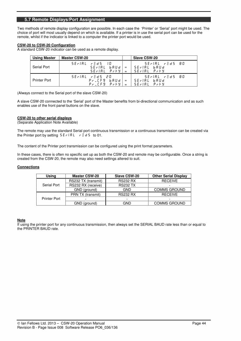
Ian Fellows Ltd. 2013 – CSW-20 Operation Manual Page 44 Revision B - Page Issue 008 Software Release PO6_036/136
5.7 Remote Displays/Port Assignment Two methods of remote display configuration are possible. In each case the ‘Printer’ or ‘Serial’ port might be used. The choice of port will most usually depend on which is available. If a printer is in use the serial port can be used for the remote, whilst if the indicator is linked to a computer the printer port would be used. CSW-20 to CSW-20 Configuration A standard CSW-20 indicator can be used as a remote display.
Using Master Master CSW-20 Slave CSW-20
Serial Port Serial rmds 10
Serial baud
Serial Prty
= =
Serial rmds 80
Serial baud
Serial Prty
Printer Port Serial rmds 20
Pr_cfg baud
Pr_cfg Prty
= =
Serial rmds 80
Serial baud
Serial Prty (Always connect to the Serial port of the slave CSW-20) A slave CSW-20 connected to the ‘Serial’ port of the Master benefits from bi-directional communication and as such enables use of the front panel buttons on the slave. CSW-20 to other serial displays (Separate Application Note Available) The remote may use the standard Serial port continuous transmission or a continuous transmission can be created via
the Printer port by setting Serial rmds to 01.
The content of the Printer port transmission can be configured using the print format parameters. In these cases, there is often no specific set up as both the CSW-20 and remote may be configurable. Once a string is created from the CSW-20, the remote may also need settings altered to suit. Connections
Using Master CSW-20 Slave CSW-20 Other Serial Display
RS232 TX (transmit) RS232 RX RECEIVE
RS232 RX (receive) RS232 TX - Serial Port
GND (ground) GND COMMS GROUND
PRN TX (transmit) RS232 RX RECEIVE
- - - Printer Port
GND (ground) GND COMMS GROUND
Note If using the printer port for any continuous transmission, then always set the SERIAL BAUD rate less than or equal to the PRINTER BAUD rate.

Ian Fellows Ltd. 2013 – CSW-20 Operation Manual Page 45 Revision B - Page Issue 008 Software Release PO6_036/136
6. DIAGNOSTICS During parameter entry, erroneous values will result in the parameter not being stored and the display reverting to the corresponding sub-menu heading display but with a ‘x?’ appended to that display (‘x’ is a diagnostic, and can be used to determine the nature of the error). Parameter Entry Error Codes - See Serial Responses Section 5.2 ?? Entered parameter out of allowed range.
C? Command or parameter value not permitted under current access level (Usually re-interpreted as noPASSnoPASSnoPASSnoPASS). D? Start of calibration deadload acquisition at each PGA setting.
In response to a dEAddEAddEAddEAd calibrate deadload command ?? If deadload outside +/- 40 mV. M? Excessive motion.
In response to a CALCALCALCAL or CALAtCALAtCALAtCALAt calibrate command F? If attempt to calibrate without valid deadload having been previously acquired. (trade only). A? Calibration weight is not within 12.5% - 100% of capacity (‘toP’), or l.s.d. incompatible with ‘DISP’.
L? If input resolution <1µµµµV/e in ‘trade’ mode or <0.1µµµµV/e in non trade mode. H? (Calibn Deadload) End of each deadload acquisition step. (Calibn Span) Loadcell input too high during span acquisition (>100mV) Full Display Status/Error Messages
STATUS MESSAGES
Abort?Abort?Abort?Abort? Do you wish to abort this calibration, forgetting all alterations? ENTER or to confirm else back to calibrate.
ACCESSACCESSACCESSACCESSn Displays ACCESS LEVEL achieved on entry to MENU (n = 0-3).
AddAddAddAdd nnnnnnnn
Place requested number of sample parts on weighpan and press ENTER Else press to alter sample number or ‘CAnCEL’.
BUSYBUSYBUSYBUSY Awaiting ‘CALm’ timeout or Flashcard is busy (please wait).
CLEArCLEArCLEArCLEAr nnnn Flashcard clearing in progress. ‘n’ indicates progress.
FLASHFLASHFLASHFLASH Flashcard transaction in progress (please wait).
NEg NEg NEg NEg Print/store inhibited - Print disallowed when weight is negative.
NonENonENonENonE Selected flashcard location has been erased.
NoPASSNoPASSNoPASSNoPASS Access denied; enter password or operate internal button (if authorised).
PASSPASSPASSPASS . Enter Password (or press MODE to skip). ‘ . ’ indicates current digit entry position.
PrInt PrInt PrInt PrInt Printing in progress.
PSHbUt PSHbUt PSHbUt PSHbUt Press Internal (S1) pushbutton (or press MODE to skip).
REAd_EREAd_EREAd_EREAd_E Parameters read from permanent to working memory.
SndIngSndIngSndIngSndIng Flashcard dump to printer in progress (please wait).
StorEdStorEdStorEdStorEd Newly edited parameter written to permanent memory store.
SUrE?SUrE?SUrE?SUrE? Do you wish to accept this calibration? ENTER or if so, else back to calibrate.
Too LoToo LoToo LoToo Lo Print/store inhibited - Net Weight is below Minimum.
UnLoAd UnLoAd UnLoAd UnLoAd Print/store inhibited - change in weight since last print is too small.
UnUSEdUnUSEdUnUSEdUnUSEd Flashcard location with nothing yet stored.

Ian Fellows Ltd. 2013 – CSW-20 Operation Manual Page 46 Revision B - Page Issue 008 Software Release PO6_036/136
DIAGNOSTIC MESSAGES - Some require service assistance.
--------20%20%20%20%--------
-------- 4%4%4%4%-------- Cannot re-zero because outside 20% (or 4%, dependent on condition) zero setting limits. If at switch-on, either adjust weight or press SET ZERO to re-select previous zero setting. New zero (within +/-10% of original calibration) may be set with SET ZERO+MODE.
AAAA----d?d?d?d? Analogue to Digital converter interface failure.
BUttS?BUttS?BUttS?BUttS? Keyboard fail ~ shorted tracks ... service required.
CCCCCCCCCCCCCCCCCCCCCCCC Serial port acknowledge not received so Flash store not performed. Check serial interface and host computer.
CELL?CELL?CELL?CELL? Faulty or incorrectly connected loadcell.
CLOCt?CLOCt?CLOCt?CLOCt? Failure to Read or Write to Clock - Service required
DEFAULnDEFAULnDEFAULnDEFAULn Waiting to load default parameters. ‘n’ (0,1 or 2) indicates default level. Internal pushbutton initiates loading.
DIAg nDIAg nDIAg nDIAg n System Error... service required.
Dog?Dog?Dog?Dog? Watchdog failure
DroPoUtDroPoUtDroPoUtDroPoUt Power failure or internal power fault
EEProm?EEProm?EEProm?EEProm? EEProm checksum failure ~ corrupted information. Attempt to reload defaults.
I2CI2CI2CI2C rrrr Failure to read (write) from (to) Clock/RAM or EEPROM
oUt_toLoUt_toLoUt_toLoUt_toL Out of printable range in batch mode.
rom?rom?rom?rom? Program ROM checksum failure
FAULtYnFAULtYnFAULtYnFAULtYn Print/store inhibited- Printer fault due to power, connection, paper low or handshake fail.
StACkStACkStACkStACk System error
EEProMbEEProMbEEProMbEEProMb Power failed while backing up new parameter (possible corruption). allows resumption (check last entered data). Internal S1 pushbutton forces a default 2 reset.
EEProMcEEProMcEEProMcEEProMc Potentially fatal error in stored parameters ~ use Internal S1 pushbutton to force default 2 reset ~ all user data will be lost.
EEProMFEEProMFEEProMFEEProMF Failure to correctly verify parameter written to EEPROM…service required.
CloCk?nCloCk?nCloCk?nCloCk?n Failure to read/write to Clock/RAM (n='w' write fail, ='r' read fail
F dEAdnF dEAdnF dEAdnF dEAdn Deadload calibration in progress ~ part of calibration (rotating zero in MSD).
FLASH?FLASH?FLASH?FLASH? Awaiting Flashcard initialisation, please wait. If FLASH?eFLASH?eFLASH?eFLASH?e /0000/SSSS consult factory for assistance
F CALnF CALnF CALnF CALn Span calibration in process. msd F is rotating zero
LoLoLoLo----bAtbAtbAtbAt Clock/RAM failed to hold data while power down…service required.
Not CALNot CALNot CALNot CAL Not yet calibrated. Perform a calibration.
r FAILr FAILr FAILr FAIL Ram failure Also, during warm-up
Po6 2345Po6 2345Po6 2345Po6 2345 Software revision number
tAn 123tAn 123tAn 123tAn 123 Traceable Access Number (number of changes performed at ACCESS LEVEL 2; typically shows number of calibration procedures performed)

Ian Fellows Ltd. 2013 – CSW-20 Operation Manual Page 47 Revision B - Page Issue 008 Software Release PO6_036/136
7. APPENDIX
7.1 Specifications
Features High Quality – Low Cost.
7 Digit, bright, easy to read, large LED display.
Stainless steel enclosure with bracket for wall/desk mount.
Connections via 5mm press clamps.
Trade Approved for any R60 loadcells.
High resolution weighing performance.
Multi point linearity adjustment.
Accommodates extremes of dead load and signal.
Superb digital weight filtering with fast settle times.
x10 resolution test mode.
Configuration via front panel or serial communication.
Firmware upgrades via serial port.
Two serial ports, printer port can be used for remote display.
Preset Tare & Memory tares
Semi automatic tare and set zero functions.
3 outputs, 2 inputs as standard.
Real time clock as standard.
Versatile print formatting.
PLU's for A/N text, setpoints, part weights and totals.
Multi-drop communications.
Sophisticated fill control with fast predictive cut off
Variety of setpoint operating modes.
Many advanced software features.
Options 15 bit Analogue Output 4-20mA or 0-10V.
Flash Electronic Tally Record (Alibi device).
Integrated WiFi or Ethernet.
ModBus Communications.
24V DC powered version.
General Specifications Display mm 7 Red LED digits 20mm
Front Panel Membrane with tactile metal domes, Beep response, 5 button operation.
Annunciators 4 LEDS (Motion/Zero/Net/Gross)
Internal Resolution, counts 24 bit ADC (1:16,777,215)
Maximum Display Resolution (trade) divisions 10,000
Maximum Display Resolution (non-trade) divisions 500,000 (x10 test mode)
EC Approvals OIML Class III + IIII s certificate NWML UK2677
Input Signal Range mV/V -6.5 → 6.5
Zero Offset Range % 100% of Input Signal Range
ADC Conversion Rate Hz 50 (25/100*)
Linearity error %FS < ± 0.0015% (+ digital correction)
Differential non linearity ± 0.5 LSB
Span temperature coefficient ppm/°C 1.6
Zero temperature coefficient µV/oC < 0.005
Power consumption (typical) W 5-10
Common Mode Rejection (@500Hz) dB 120
Power Supply Rejection (@500Hz) dB 120
Operating voltage V 230/115Vac (Selectable) 12-28VdC *
Weight kg 2.5kg (shipping 2.9kg)
Transducer Input Transducer type (4 or 6 wire) Resistive, full bridge
Specifications Transducer input resistance Ω min 43Ω (up to 8 x 350Ω cells)
Excitation voltage Vdc 5 (nominal)
Minimum signal requirement (approved) µV/e. 1
Minimum signal requirement (non-approved) µV/e 0.1
Input impedance MΩ ≥ 20 (sense and signal)
Serial Communication Communication Ports 1.Comms RS232 or RS485 2.Printer port RS232 (TX/Busy)
Baud rate bits/sec 2400, 4800, 9600, 19200, 38400
Protocol 7/8 data bits, odd/even/no parity, 1/2 stop bits
Maximum continuous data Rate (test mode) Hz 50
Communication protocol Ascii or ModBus*
Environmental Operating Temperature °C -10 → 40
Storage Temperature °C -10 → 70
EMC Immunity/Emissions EN45501, EN50082-2
Sealing IP66
Case Grained 304 Stainless Steel Swivel Stand (bench or wall mount)
I/O Analogue output* 0-10V or 4-20ma* 15 bit (adjustable range) Max drive load for 4-20mA: 500R(active)/1200R (passive)
Inputs 2 Opto coupled inputs <6V off; >10 –30V on (Supply rail on board)
Outputs 3 Darlington type transistors Max OFF voltage 27V; Max ON current 60mA Leakage <0.1ma Switched + or -
* According to specification

Ian Fellows Ltd. 2013 – CSW-20 Operation Manual Page 48 Revision B - Page Issue 008 Software Release PO6_036/136
7.2 Calibration Transfer For non-certified, low accuracy applications (e.g. silo contents monitoring) where in-service re-calibration is often extremely difficult, it is possible to replace the ‘baseboard’ and simply transfer across old calibration constants (with some modification to account for slightly different characteristics). The overall accuracy should not vary by more than 0.5%. It is in any case a good idea to maintain a record of all of the parameters mentioned in the first ‘bullet’ below, plus
ZEROZEROZEROZERO and gAIngAIngAIngAIn parameters from AnALog_AnALog_AnALog_AnALog_ if an analogue output module is installed. Also, if a printer is
installed, print out the ADC Configuration and Memory Image by setting AdCAdCAdCAdC 1111 then mEmmEmmEmmEm 1111 in EngCFg_EngCFg_EngCFg_EngCFg_ . If the existing baseboard parameters should ever be lost, they may enable a service technician to restore calibration exactly, without having to physically re-calibrate. When replacing a ‘baseboard’ ~
• Have a record of all relevant (i.e. to you) previous system parameters (always keep an up-to-date record),
especially UnPoUnPoUnPoUnPo, FACtFACtFACtFACt, dEdFdEdFdEdFdEdF, CALFCALFCALFCALF, CFrgCFrgCFrgCFrg. Restoring to EEPROM level 2 access Calibration data can be restored into EEPROM should data be lost for any reason by re-entering the calibration data as follows (this data should ALWAYS be recorded at the time of calibration).
In CALIbn_ CALIbn_ CALIbn_ CALIbn_ re-enter the original dISp, toPtoPtoPtoP and, if known, the CALAtCALAtCALAtCALAt value. Re-enter the ADC Configuration data parameters in the printout order. ADC Configuration
Serial Cmd Description Typical Parameter
MF Millivolt Factor * 0263295 FACt FACt FACt FACt
CG Config Reg %060000 CFrg CFrg CFrg CFrg
DD Deadload o/s 7960170 dEdF dEdF dEdF dEdF
CF Cal Factor 0201050 CALF CALF CALF CALF
IZ Init Zero o/s 0005026 Zero Zero Zero Zero
ZE Working Zero o/s 0000000 ZoFF ZoFF ZoFF ZoFF Items marked * require the calibration button to be pressed when being entered.
Set UCAL UCAL UCAL UCAL to zero (Serial Cmd SU) and ensure that the FILt FILt FILt FILt setting is restored. Restoring Calibration with Replacement Baseboard 1. Install and power up the replacement baseboard.
2. In CALIbn_CALIbn_CALIbn_CALIbn_ re-enter the original dispdispdispdisp toptoptoptop and CACACACALAtLAtLAtLAt
3. Re-enter the original calibration data CFrgCFrgCFrgCFrg dedfdedfdedfdedf calfcalfcalfcalf zerozerozerozero and zoffzoffzoffzoff 4. Enter the old FACT value into the CHgF parameter. This will cause a new CALF to be calculated, alternatively, as
before, this can be re-calculated manually. 5. Reset the Filter Band FILt
6. Force an initial zero with the scale unloaded or re-acquire the deaddeaddeaddead 7. If default reload has occurred then the UCAL parameter must be set to zero.

Ian Fellows Ltd. 2013 – CSW-20 Operation Manual Page 49 Revision B - Page Issue 008 Software Release PO6_036/136
7.3 Replacing Legends 1. A suitably prepared printed slip can be slid into the legend slot accessible from the rear without board removal 2. DO NOT try to remove the front panel membrane from the front; it is glued into place and will be damaged. 3. Turn off power. 4. Remove the lid securing screws (Any seal has to be broken). 5. The front panel legend slot is now accessible. 6. Insert legend ensuring that it is fully home and square – see diagram. The units legend is factory fitted. Replacement requires board removal and should be attempted by qualified personnel only.
Tail
Units Insert - Factory FittedFold insert back on itself and sandwich between the display panel and the support plate to hold in place.
Legend Insert
7.4 Dimensions CSW-20 All dimensions are approximate and measured in millimetres unless otherwise stated.
MAX =
MIN =
e = d =
183.3
159.8
I an Fel l ow s CSW- 20
94
56
19
4 off Ø7.0 typical
20411.4
226.7
66.4
33.2
62
222.3
ENTER
MODE PRINT
III
SEMI
AUTO
TARE
TESTSETZERO
kg
GROSSNET MOTIONZERO

Ian Fellows Ltd. 2013 – CSW-20 Operation Manual Page 50 Revision B - Page Issue 008 Software Release PO6_036/136
8. MENU TABLES
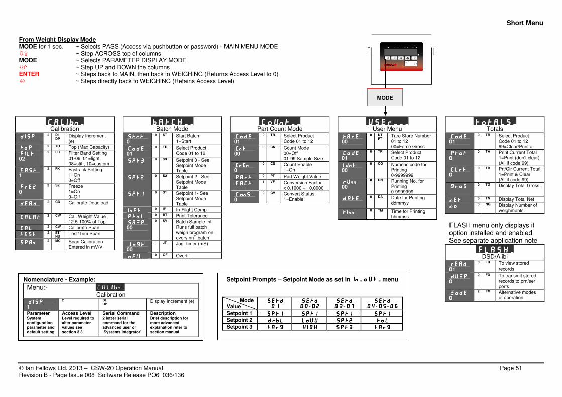
Short Menu
Ian Fellows Ltd. 2013 – CSW-20 Operation Manual Page 51 Revision B - Page Issue 008 Software Release PO6_036/136
From Weight Display Mode MODE for 1 sec. ~ Selects PASS (Access via pushbutton or password) - MAIN MENU MODE ~ Step ACROSS top of columns MODE ~ Selects PARAMETER DISPLAY MODE ~ Step UP and DOWN the columns ENTER ~ Steps back to MAIN, then back to WEIGHING (Returns Access Level to 0) ~ Steps directly back to WEIGHING (Retains Access Level)
Calibn_Calibn_Calibn_Calibn_ Calibration
DispDispDispDisp 2 DI DP
Display Increment (e)
TopTopTopTop 2 TO Top (Max Capacity)
FiltFiltFiltFilt 02
2 FB Filter Band Setting 01-08, 01=light, 08=stiff, 10=custom
FastFastFastFast 1
2 FK Fastrack Setting 1=On 0=Off
FrezFrezFrezFrez 0
2 SZ Freeze 1=On 0=Off
deaddeaddeaddead
2 CD Calibrate Deadload
CalatCalatCalatCalat 2 CW Cal. Weight Value 12.5-100% of Top
calcalcalcal 2 CW Calibrate Span
testtesttesttest 2 ET/NU
Test/Trim Span
spanspanspanspan 2 MC Span Calibration Entered in mV/V
Batch__Batch__Batch__Batch__ Batch Mode
StrtStrtStrtStrt 0
0 ST Start Batch 1=Start
CodeCodeCodeCode 01
0 TR Select Product Code 01 to 12
Spt3Spt3Spt3Spt3 0 S3 Setpoint 3 - See Setpoint Mode Table
Spt2Spt2Spt2Spt2 0 S2 Setpoint 2 - See Setpoint Mode Table
Spt1Spt1Spt1Spt1 0 S1 Setpoint 1- See Setpoint Mode Table
InftInftInftInft 0 IF In-Filght Comp.
PtolPtolPtolPtol 0 BT Print Tolerance
SampSampSampSamp 00
0 SV Batch Sample Int. Runs full batch weigh program on every nn
th batch
JogtJogtJogtJogt
00 1 JT Jog Timer (mS)
OfilOfilOfilOfil 0 OF Overfill
Count__Count__Count__Count__ Part Count Mode
CodeCodeCodeCode 01
0 TR Select Product Code 01 to 12
CntCntCntCnt 00
0 CN Count Mode 00=Off 01-99 Sample Size
CnenCnenCnenCnen 0
0 CS Count Enable 1=On
partpartpartpart 0 PT Part Weight Value
factfactfactfact 1 VF Conversion Factor x 0.1000 – 10.0000
ConsConsConsCons 0
0 CV Convert Status 1=Enable
User___User___User___User___ User Menu
TareTareTareTare 00
0 NT FT
Tare Store Number 01 to 12 00=Force Gross
CodeCodeCodeCode 01
0 TR Select Product Code 01 to 12
IIIIdntdntdntdnt 00
0 CO Numeric code for Printing 0-9999999
RunnRunnRunnRunn 00
0 RN Running No. for Printing 0-9999999
DateDateDateDate
0 DA Date for Printing ddmmyy
TinnTinnTinnTinn 0 TM Time for Printing hhmmss
Totals_Totals_Totals_Totals_ Totals
CodeCodeCodeCode 01
0 TR Select Product Code 01 to 12 99=Clear/Print all
PtotPtotPtotPtot 0
0 TA Print Current Total 1=Print (don’t clear) (All if code 99)
ClrtClrtClrtClrt 0
0 TB Prt/Clr Current Total 1=Print & Clear (All if code 99)
GrosGrosGrosGros
0 TG Display Total Gross
NetNetNetNet 0 TN Display Total Net
NoNoNoNo 0 NG Display Number of weighments
FLASH menu only displays if option installed and enabled See separate application note
FLASH_FLASH_FLASH_FLASH_ DSD/Alibi
readreadreadread 01
0 FR To view stored records
dumpdumpdumpdump 0
0 FD To transmit stored records to prn/ser ports
modemodemodemode 0
2 FM Alternative modes of operation
Setpoint Prompts – Setpoint Mode as set in in_out_in_out_in_out_in_out_ menu
Mode Value
Setd Setd Setd Setd
01010101
SetdSetdSetdSetd
00000000----02020202
Setd Setd Setd Setd
03030303----07070707
SetdSetdSetdSetd
04040404----05050505----06060606
Setpoint 1 Spt1Spt1Spt1Spt1 Spt1Spt1Spt1Spt1 Spt1Spt1Spt1Spt1 Spt1Spt1Spt1Spt1
Setpoint 2 drbldrbldrbldrbl louulouulouulouu Spt2Spt2Spt2Spt2 TolTolTolTol
Setpoint 3 targtargtargtarg highhighhighhigh Spt3Spt3Spt3Spt3 targtargtargtarg
Nomenclature - Example:
Menu:- Calibn_ Calibration
dispdispdispdisp 1
2 DI DP
Display Increment (e)
Parameter System configuration parameter and default setting
Access Level Level required to alter parameter values see section 3.3.
Serial Command 2 letter serial command for the advanced user or ‘Systems Integrator’
Description Brief description for more advanced explanation refer to section manual
MODE
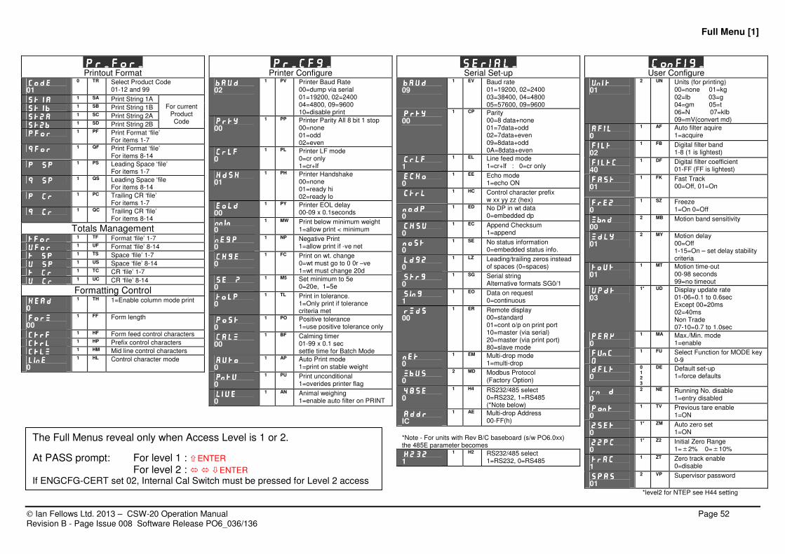
Full Menu [1]
Ian Fellows Ltd. 2013 – CSW-20 Operation Manual Page 52 Revision B - Page Issue 008 Software Release PO6_036/136
PR_FOR_PR_FOR_PR_FOR_PR_FOR_ Printout Format
CODECODECODECODE
01
0 TR Select Product Code 01-12 and 99
ST1AST1AST1AST1A 1 SA Print String 1A
ST1BST1BST1BST1B 1 SB Print String 1B
ST2AST2AST2AST2A 1 SC Print String 2A
ST2BST2BST2BST2B 1 SD Print String 2B
For current
Product Code
PFORPFORPFORPFOR 1 PF Print Format ‘file’
For items 1-7
QFORQFORQFORQFOR 1 QF Print Format ‘file’
For items 8-14
P SPP SPP SPP SP 1 PS Leading Space ‘file’
For items 1-7
Q SPQ SPQ SPQ SP 1 QS Leading Space ‘file
For items 8-14
P CRP CRP CRP CR 1 PC Trailing CR ‘file’
For items 1-7
Q CRQ CRQ CRQ CR 1 QC Trailing CR ‘file’
For items 8-14
Totals Management TFORTFORTFORTFOR 1 TF Format ‘file’ 1-7
UFOUFOUFOUFORRRR 1 UF Format ‘file’ 8-14
T SPT SPT SPT SP 1 TS Space ‘file’ 1-7
U SPU SPU SPU SP 1 US Space ‘file’ 8-14
T CRT CRT CRT CR 1 TC CR ‘file’ 1-7
U CRU CRU CRU CR 1 UC CR ‘file’ 8-14
Formatting Control HEADHEADHEADHEAD 0
1 TH 1=Enable column mode print
FORMFORMFORMFORM 00
1 FF Form length
CTRFCTRFCTRFCTRF 1 HF Form feed control characters
CTRLCTRLCTRLCTRL 1 HP Prefix control characters
CTlMCTlMCTlMCTlM 1 HM Mid line control characters
LineLineLineLine 0
1 HL Control character mode
PR_CFG_PR_CFG_PR_CFG_PR_CFG_ Printer Configure
BAUDBAUDBAUDBAUD 02
1 PV Printer Baud Rate 00=dump via serial 01=19200, 02=2400 04=4800, 09=9600 10=disable print
PrtyPrtyPrtyPrty 00
1 PP Printer Parity All 8 bit 1 stop 00=none 01=odd 02=even
CRLFCRLFCRLFCRLF 0
1 PL Printer LF mode 0=cr only 1=cr+lf
HdshHdshHdshHdsh 01
1 PH Printer Handshake 00=none 01=ready hi 02=ready lo
EOLDEOLDEOLDEOLD 00
1 PY Printer EOL delay 00-09 x 0.1seconds
NNINNNINNNINNNIN 0
1 MW Print below minimum weight 1=allow print < minimum
NEGPNEGPNEGPNEGP 0
1 NP Negative Print 1=allow print if -ve net
CHGECHGECHGECHGE 0
1 FC Print on wt. change 0=wt must go to 0 0r –ve 1=wt must change 20d
SE ?SE ?SE ?SE ? 0
1 M5 Set minimum to 5e 0=20e, 1=5e
TOLPTOLPTOLPTOLP 0
1 TL Print in tolerance. 1=Only print if tolerance criteria met
POSTPOSTPOSTPOST 0
1 PO Positive tolerance 1=use positive tolerance only
CALMCALMCALMCALM 00
1 BF Calming timer 01-99 x 0.1 sec settle time for Batch Mode
AUTOAUTOAUTOAUTO 0
1 AP Auto Print mode 1=print on stable weight
PntuPntuPntuPntu
0 1 PU Print unconditional
1=overides printer flag
LIVELIVELIVELIVE 0
1 AN Animal weighing 1=enable auto filter on PRINT
Serial_Serial_Serial_Serial_ Serial Set-up
BaudBaudBaudBaud 09
1 EV Baud rate 01=19200, 02=2400 03=38400, 04=4800 05=57600, 09=9600
PrtyPrtyPrtyPrty
00 1 CP Parity
00=8 data+none 01=7data+odd 02=7data+even 09=8data+odd 0A=8data+even
CrlfCrlfCrlfCrlf 1
1 EL Line feed mode 1=cr+lf : 0=cr only
EchoEchoEchoEcho 0
1 EE Echo mode 1=echo ON
CtrlCtrlCtrlCtrl 1 HC Control character prefix w xx yy zz (hex)
NodpNodpNodpNodp 0
1 ED No DP in wt data 0=embedded dp
chsuchsuchsuchsu 0
1 EC Append Checksum 1=append
nostnostnostnost 0
1 SE No status information 0=embedded status info.
LdgzLdgzLdgzLdgz 0
1 LZ Leading/trailing zeros instead of spaces (0=spaces)
STRgSTRgSTRgSTRg 0
1 SG Serial string Alternative formats SG0/1
SingSingSingSing 1
1 EO Data on request 0=continuous
RmdsRmdsRmdsRmds 00
1 ER Remote display 00=standard 01=cont o/p on print port 10=master (via serial) 20=master (via print port) 80=slave mode
netnetnetnet 0
1 EM Multi-drop mode 1=multi-drop
MbusMbusMbusMbus 0
2 MD Modbus Protocol (Factory Option)
485E485E485E485E 0
1 H4 RS232/485 select 0=RS232, 1=RS485 (*Note below)
addraddraddraddr IC
1 AE Multi-drop Address 00-FF(h)
*Note - For units with Rev B/C baseboard (s/w PO6.0xx) the 485E parameter becomes
H232H232H232H232 1
1 H2 RS232/485 select 1=RS232, 0=RS485
Config_Config_Config_Config_ User Configure
UnitUnitUnitUnit
01 2 UN Units (for printing)
00=none 01=kg 02=lb 03=g 04=gm 05=t 06=N 07=klb 09=mV(convert md)
AfilAfilAfilAfil
0 1 AF Auto filter aquire
1=acquire
FiltFiltFiltFilt 02
1 FB Digital filter band 1-8 (1 is lightest)
FiltcFiltcFiltcFiltc 40
1 DF Digital filter coefficient 01-FF (FF is lightest)
FastFastFastFast 01
1 FK Fast Track 00=Off, 01=On
FrFrFrFrEzEzEzEz 0
1 SZ Freeze 1=On 0=Off
MbndMbndMbndMbnd
00 2 MB Motion band sensitivity
MdlyMdlyMdlyMdly
01 2 MY Motion delay
00=Off 1-15=On – set delay stability criteria
ToutToutToutTout 01
1 MT Motion time-out 00-98 seconds 99=no timeout
UpdtUpdtUpdtUpdt
03 1* UD Display update rate
01-06=0.1 to 0.6sec Except 00=20ms 02=40ms Non Trade 07-10=0.7 to 1.0sec
PEAKPEAKPEAKPEAK
0 1 MA Max./Min. mode
1=enable
FuncFuncFuncFunc
0000
1 FU Select Function for MODE key 0-9
DfltDfltDfltDflt
0 0 1 2 3
DE Default set-up 1=force defaults
Rn dRn dRn dRn d
0 2 NE Running No. disable
1=entry disabled
PontPontPontPont
0 1 TV Previous tare enable
1=ON
ZsetZsetZsetZset
0 1* ZM Auto zero set
1=ON
ZzpcZzpcZzpcZzpc
0 1* Z2 Initial Zero Range
1=±2% 0=±10%
TracTracTracTrac
1 1 ZT Zero track enable
0=disable
SpasSpasSpasSpas 01
2 VP Supervisor password
*level2 for NTEP see H44 setting
The Full Menus reveal only when Access Level is 1 or 2.
At PASS prompt: For level 1 : ENTER For level 2 : ENTER
If ENGCFG-CERT set 02, Internal Cal Switch must be pressed for Level 2 access
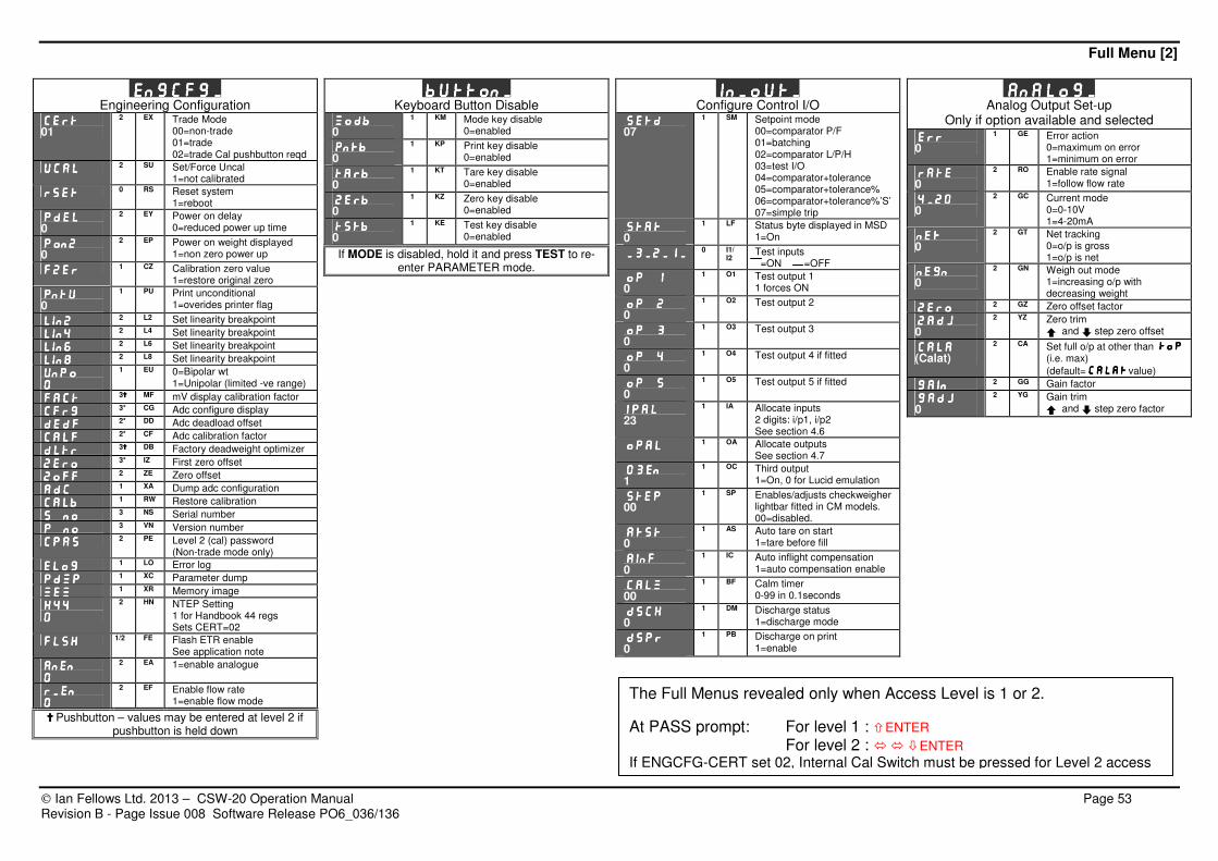
Full Menu [2]
Ian Fellows Ltd. 2013 – CSW-20 Operation Manual Page 53 Revision B - Page Issue 008 Software Release PO6_036/136
Engcfg_Engcfg_Engcfg_Engcfg_ Engineering Configuration
CERTCERTCERTCERT 01
2 EX Trade Mode 00=non-trade 01=trade 02=trade Cal pushbutton reqd
UcalUcalUcalUcal 2 SU Set/Force Uncal 1=not calibrated
rsetrsetrsetrset 0 RS Reset system 1=reboot
PdelPdelPdelPdel 0
2 EY Power on delay 0=reduced power up time
PonzPonzPonzPonz 0
2 EP Power on weight displayed 1=non zero power up
FzeFzeFzeFzerrrr 1 CZ Calibration zero value 1=restore original zero
PntuPntuPntuPntu
0 1 PU Print unconditional
1=overides printer flag
Lin2Lin2Lin2Lin2 2 L2 Set linearity breakpoint
Lin4Lin4Lin4Lin4 2 L4 Set linearity breakpoint
Lin6Lin6Lin6Lin6 2 L6 Set linearity breakpoint
Lin8Lin8Lin8Lin8 2 L8 Set linearity breakpoint
UNPOUNPOUNPOUNPO
0000
1 EU 0=Bipolar wt 1=Unipolar (limited -ve range)
FactFactFactFact 3 MF mV display calibration factor
CFRGCFRGCFRGCFRG 3* CG Adc configure display
DedfDedfDedfDedf 2* DD Adc deadload offset
CalfCalfCalfCalf 2* CF Adc calibration factor
DLTRDLTRDLTRDLTR 3 DB Factory deadweight optimizer
ZeroZeroZeroZero 3* IZ First zero offset
ZoffZoffZoffZoff 2 ZE Zero offset
ADCADCADCADC 1 XA Dump adc configuration
CalbCalbCalbCalb 1 RW Restore calibration
S noS noS noS no 3 NS Serial number
P noP noP noP no 3 VN Version number
CpasCpasCpasCpas 2 PE Level 2 (cal) password
(Non-trade mode only)
ELOGELOGELOGELOG 1 LO Error log
PdmpPdmpPdmpPdmp 1 XC Parameter dump
MemMemMemMem 1 XR Memory image
H44H44H44H44
0000
2 HN NTEP Setting 1 for Handbook 44 regs Sets CERT=02
FLSHFLSHFLSHFLSH 1/2 FE Flash ETR enable
See application note
anenanenanenanen
0000
2 EA 1=enable analogue
R_enR_enR_enR_en
0000
2 EF Enable flow rate 1=enable flow mode
Pushbutton – values may be entered at level 2 if pushbutton is held down
Button_Button_Button_Button_ Keyboard Button Disable
ModbModbModbModb 0
1 KM Mode key disable 0=enabled
pntbpntbpntbpntb 0
1 KP Print key disable 0=enabled
tarbtarbtarbtarb 0
1 KT Tare key disable 0=enabled
zerbzerbzerbzerb 0
1 KZ Zero key disable 0=enabled
tstbtstbtstbtstb 0
1 KE Test key disable 0=enabled
If MODE is disabled, hold it and press TEST to re-enter PARAMETER mode.
In_out_In_out_In_out_In_out_ Configure Control I/O
SetdSetdSetdSetd 07
1 SM Setpoint mode 00=comparator P/F 01=batching 02=comparator L/P/H 03=test I/O 04=comparator+tolerance 05=comparator+tolerance% 06=comparator+tolerance%’S’ 07=simple trip
StatStatStatStat 0
1 LF Status byte displayed in MSD 1=On
_3_2_1__3_2_1__3_2_1__3_2_1_ 0 I1/ I2
Test inputs =ON =OFF
OP 1OP 1OP 1OP 1 0
1 O1 Test output 1 1 forces ON
OP 2OP 2OP 2OP 2 0
1 O2 Test output 2
OP 3OP 3OP 3OP 3 0
1 O3 Test output 3
OP 4OP 4OP 4OP 4 0
1 O4 Test output 4 if fitted
OP 5OP 5OP 5OP 5 0
1 O5 Test output 5 if fitted
IPALIPALIPALIPAL 23
1 IA Allocate inputs 2 digits: i/p1, i/p2 See section 4.6
OPALOPALOPALOPAL 1 OA Allocate outputs See section 4.7
03en03en03en03en 1
1 OC Third output 1=On, 0 for Lucid emulation
StePStePStePSteP 00
1 SP Enables/adjusts checkweigher lightbar fitted in CM models. 00=disabled.
ATSTATSTATSTATST 0
1 AS Auto tare on start 1=tare before fill
AINFAINFAINFAINF 0
1 IC Auto inflight compensation 1=auto compensation enable
CALMCALMCALMCALM 00
1 BF Calm timer 0-99 in 0.1seconds
DSCHDSCHDSCHDSCH 0
1 DM Discharge status 1=discharge mode
DSPRDSPRDSPRDSPR 0
1 PB Discharge on print 1=enable
Analog_Analog_Analog_Analog_ Analog Output Set-up
Only if option available and selected Err Err Err Err
0 1 GE Error action
0=maximum on error 1=minimum on error
RATERATERATERATE 0
2 RO Enable rate signal 1=follow flow rate
4_204_204_204_20 0
2 GC Current mode 0=0-10V 1=4-20mA
NETNETNETNET 0
2 GT Net tracking 0=o/p is gross 1=o/p is net
NEGNNEGNNEGNNEGN 0
2 GN Weigh out mode 1=increasing o/p with decreasing weight
ZEROZEROZEROZERO 2 GZ Zero offset factor
ZADJZADJZADJZADJ 0
2 YZ Zero trim r and o step zero offset
CALACALACALACALA (Calat)
2 CA Set full o/p at other than toptoptoptop (i.e. max)
(default=calatcalatcalatcalat value)
GainGainGainGain 2 GG Gain factor
gadjgadjgadjgadj 0
2 YG Gain trim r and o step zero factor
The Full Menus revealed only when Access Level is 1 or 2.
At PASS prompt: For level 1 : ENTER For level 2 : ENTER
If ENGCFG-CERT set 02, Internal Cal Switch must be pressed for Level 2 access

Ian Fellows Ltd. 2013 – CSW-20 Operation Manual Page 54 Revision B - Page Issue 008 Software Release PO6_036/136
9. BASEBOARD LAYOUT REFERENCE

Baseboard Layout
Ian Fellows Ltd. 2013 – CSW-20 Operation Manual Page 55 Revision B - Page Issue 008 Software Release PO6_036/136
Baseboard Location References: (Revision B/C version)
# Description PCB ID # Description PCB ID
1 PROCESSOR IC6 27 PNW HEADER N/A
2 INTERFACE TO DISPLAY SK1 28 COMMS (PRINTER RS232, RS232, RS485) P3 3 CAL SWITCH S1 29 PBUSY P3:12
4 BATTERY BT1 30 PTX P3:11
5 ADC – ONBOARD SURFACE MOUNT N/A 31 COM P3:10
6 LOADCELL HEADER P1 32 RXI P3:9
7 + SUPPLY P1:7 33 TXO P3:8
8 + SENSE P1:6 34 COM P3:7 9 - SENSE P1:5 35 B- P3:6
10 - SUPPLY P1:4 36 A+ P3:5
11 + SIGNAL P1:3 37 DAC (4-20mA O/P, 0-10V O/P) P3
12 - SIGNAL P1:2 38 ISINK P3:4
13 AGND P1:1 39 +18V P3:3 14 I/O HEADER P4 40 +VDC P3:2
15 0V P4:12 41 DACOM P3:1
16 +VOUT P4:11 42 115V/230V VOLTAGE SELECT FUSE F2
17 OP4+ P4:10 43 MAINS CONNECTOR SK2
18 OP5+ P4:9 44 TRANSFORMER T1
19 IP2+ P4:8 20 IP2_ P4:7
21 IP1+ P4:6
22 IP1_ P4:5
23 OP1+ P4:4
24 OP2+ P4:3
25 OP3+ P4:2 26 OP-COM P4:1
7 8 9
29
28
42 44
1
3
2
5
13
6
43
4
10 11 12 15 16 17 21 18 19 20 22 26 23 24 25
27
14
30 31 32 33 34 38 39 40 41 35 36
37

Baseboard Layout
Ian Fellows Ltd. 2013 – CSW-20 Operation Manual Page 56 Revision B - Page Issue 008 Software Release PO6_036/136
Baseboard Location References: (Revision E version)
# Description PCB ID # Description PCB ID
1 PROCESSOR IC6 27 OP3- P4:1 2 EXTENSION/FLASH ETR HEADER N/A 28 SECOND AIN INPUT – Not used/Special Build N/A
3 DISPLAY CONNECTIONS SK1 29 PNW HEADER– Not used/Special Build N/A
4 CAL SWITCH S1 30 COMMS (PRINTER RS232, RS232, RS485) P3
5 BATTERY BT1 31 PBUSY P3:12
6 ADC AREA, SMT not replaceable N/A 32 PTX P3:11
7 LOADCELL CONNECTIONS P1 33 COM P3:10 8 + SUPPLY P1:7 34 RXI P3:9
9 + SENSE P1:6 35 TXO P3:8
10 - SENSE P1:5 36 COM P3:7
11 - SUPPLY P1:4 37 RS485 B- P3:6
12 + SIGNAL P1:3 38 RS485 A+ P3:5 13 - SIGNAL P1:2 39 DAC (4-20mA O/P, 0-10V O/P) P3
14 AGND P1:1 40 ISINK P3:4
15 I/O HEADER P4 41 +18V P3:3
16 0V P4:12 42 +VDC P3:2
17 +VOUT P4:11 43 DACOM P3:1
18 IP2 P4:10 44 FUSE & VOLTAGE SELECT F2 19 IP2 P4:9 45 MAINS CONNECTOR SK2
20 IP1 P4:8 46 TRANSFORMER T1
21 IP1 P4:7 47 UNREG DC OUT N/A
22 OP1+ P4:6 48 15 BIT DAC PLUG IN OPTION HEADER DAC OUT
23 OP1- P4:5 49 15 BIT DAC PLUG IN OPTION HEADER DAC IN
24 OP2+ P4:4 50 DIAGNOSTIC LEDS 25 OP2- P4:3 51 EXTENSION I/O or COMMS INTERFACE PC1
26 OP3+ P4:2
44 46
1
4
6
7
45
5
8 9 10 14 11 12 13 16 17 18 22 19 20 21 23 27 24 25 26
29
15
31 32 33 34 35 36 40 41 42 43 37 38
30 39
2
3
28
47 48 49 51 50

Baseboard Layout
Ian Fellows Ltd. 2013 – CSW-20 Operation Manual Page 57 Revision B - Page Issue 008 Software Release PO6_036/136
Baseboard Location References: (Revision F version)
# Description PCB ID # Description PCB ID 1 PROCESSOR IC6 27 OP3- P4:1
2 EXTENSION/FLASH ETR HEADER N/A 28 SECOND AIN INPUT – Not used/Special Build N/A
3 DISPLAY CONNECTIONS SK1 29 PNW HEADER– Not used/Special Build N/A
4 CAL SWITCH S1 30 COMMS (PRINTER RS232, RS232, RS485) P3
5 BATTERY BT1 31 PBUSY P3:12 6 ADC AREA, SMT not replaceable N/A 32 PTX P3:11
7 LOADCELL CONNECTIONS P1 33 COM P3:10
8 + SUPPLY P1:7 34 RXI P3:9
9 + SENSE P1:6 35 TXO P3:8
10 - SENSE P1:5 36 COM P3:7 11 - SUPPLY P1:4 37 RS485 B- P3:6
12 + SIGNAL P1:3 38 RS485 A+ P3:5
13 - SIGNAL P1:2 39 DAC (4-20mA O/P, 0-10V O/P) P3
14 AGND P1:1 40 ISINK P3:4
15 I/O HEADER P4 41 +18V P3:3
16 0V P4:12 42 +VDC P3:2 17 +VOUT P4:11 43 DACOM P3:1
18 IP2 P4:10 44 FUSE F2
19 IP2 P4:9 45 MAINS CONNECTOR SK2
20 IP1 P4:8 46 TRANSFORMER T1
21 IP1 P4:7 47 VOLTAGE SELECT SWITCH V-SELECT
22 OP1+ P4:6 48 15 BIT DAC PLUG IN OPTION HEADER DAC OUT 23 OP1- P4:5 49 15 BIT DAC PLUG IN OPTION HEADER DAC IN
24 OP2+ P4:4 50 LED Vcc Power OK POK
25 OP2- P4:3 51 EXTENSION I/O or COMMS INTERFACE PC1
26 OP3+ P4:2 52 LED Comms RX Data RX
44 46
1
4
6
7
45 8 9 10 14 11 12 13 16 17 18 22 19 20 21 23 27 24 25 26
29
15
31 32 33 34 35 36 40 41 42 43 37 38
30 39
2
3
28
47
48 49 51 52 50
5

Ian Fellows Limited 3D/E Centurion Way
Crusader Park Warminster BA12 8BT
Tel +44(0)1985 218675 Fax +44(0)1985 218713