cta - 2014 physical programming · blink (arduino’s hello world)! /*! blink! turns on an led on...
TRANSCRIPT

CTA - 2014!
Physical Programming with Arduino !
Some sample projects…!

Arduino Uno - Arduino Leonardo look-alike!
The Board!Arduino Uno and its cheap cousin from Borderless Electronics!

Mini - Breadboard !
❖ typical solderless breadboard has side rails for positive and ground…!
❖ mini breadboards are without rails!
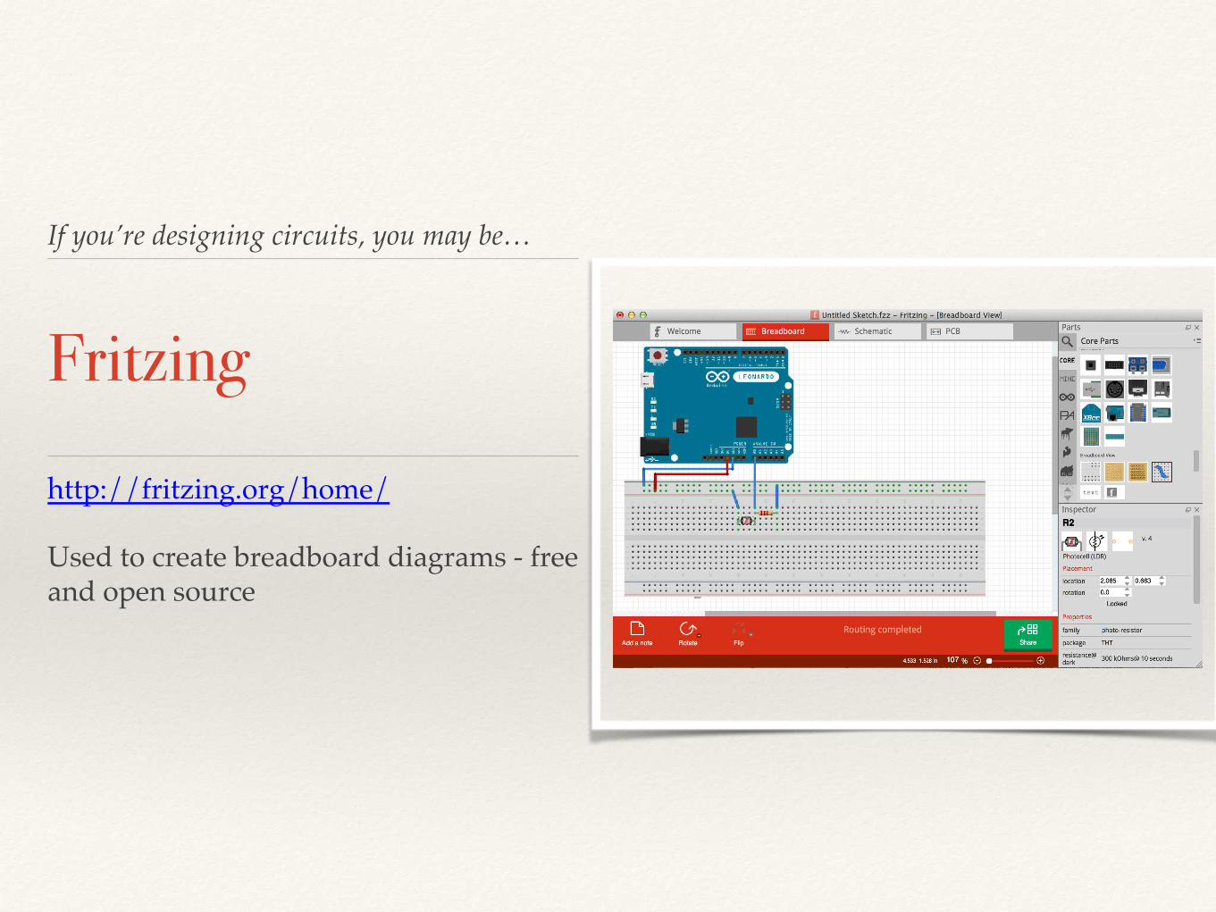
If you’re designing circuits, you may be…!
Fritzing!
http://fritzing.org/home/!!
Used to create breadboard diagrams - free and open source!!

Based on Processing…!
Arduino IDE!
Language based on C/C++(Wiring)!Based on Processing IDE!
!Processing: setup() and draw()!!Arduino: setup() and loop()!
TONS of examples:!• http://arduino.cc/en/Tutorial/
HomePage !• https://learn.adafruit.com/!
!

Some Basics…!
Compile/Download!
Select Tools>Board>Leonardo!!
Select File>Examples> whichever !!
Select ‘Check’ for compile!!
Select ‘Arrow’ to download to board!!
!

Blink (Arduino’s Hello World)!
/*!
Blink!
Turns on an LED on for one second, then off for one second,
repeatedly.!
This example code is in the public domain.!
*/!
!
// Pin 13 has an LED connected on most Arduino boards and!
// already has a resistor built in. Otherwise put resistor in!
// give it a name:!
!
int led = 13;!!
// the setup routine runs once when you press reset:!
void setup() { ! // initialize the digital pin as an output.!
pinMode(led, OUTPUT); !}!
!
// the loop routine runs over and over again forever:!
void loop() {!
digitalWrite(led, HIGH); // turn the LED on! delay(1000); // wait for a second!
digitalWrite(led, LOW); // turn the LED off! delay(1000); // wait for a second!}!

Light Sensing!
/*!
Photoresistor !
Turns on an LED on when light level is below threshold. Open
the serial monitor to see the light values Tools>Serial Monitor!
!
*/!
!
!
int led = 11;!int lightPin = 0;!
!
// the setup routine runs once when you press reset:!
void setup() { !
// initialize the digital pin as an output.! Serial.begin(9600);! pinMode(led, OUTPUT); !
}!!
// the loop routine runs over and over again forever:!
void loop() {! Serial.println(analogRead(lightPin)); // turn the LED on
(HIGH is the voltage level)!
delay(100); // wait for a second!
if (analogRead(lightPin)>900){! !digitalWrite(led, HIGH); } // turn the LED off by !// making the voltage HIGH!
! else{!
digitalWrite(led, LOW);!}!}!
!

Piezo Speaker !/*!
Melody!
!
Plays a melody !
!
circuit:!
* 8-ohm speaker on digital pin 8!
!
*/!
#include "pitches.h"!!
// notes in the melody:!
int melody[] = {!
NOTE_C4, NOTE_G3,NOTE_G3, NOTE_A3, NOTE_G3,0, NOTE_B3, NOTE_C4};!!
// note durations: 4 = quarter note, 8 = eighth note, etc.:!
int noteDurations[] = {! 4, 8, 8, 4,4,4,4,4 };!
!
void setup() {! // iterate over the notes of the melody:!
for (int thisNote = 0; thisNote < 8; thisNote++) {!!
// to calculate the note duration, take one second ! // divided by the note type.! //e.g. quarter note = 1000 / 4, eighth note = 1000/8, etc.!
int noteDuration = 1000/noteDurations[thisNote];! tone(8, melody[thisNote],noteDuration);!!
// to distinguish the notes, set a minimum time between them.! // the note's duration + 30% seems to work well:!
int pauseBetweenNotes = noteDuration * 1.30;! delay(pauseBetweenNotes);! // stop the tone playing:!
noTone(8);! }!
}!!
void loop() {!
// no need to repeat the melody.!}!

Servo Motor !
!
!
#include <Servo.h> !
!
Servo myservo; // create servo object to control a servo !
// a maximum of eight servo objects can be !! ! ! // created !
!
int pos = 0; // variable to store the servo position ! !
void setup() !{ ! myservo.attach(9); // attaches the servo on pin 9 to the servo !
} ! !
!
void loop() !{ !
for(pos = 0; pos < 180; pos += 1) // goes from 0 to 180 ! { // in steps of 1 degree ! myservo.write(pos); //go to position 'pos' !
delay(15); // waits 15ms! } !
for(pos = 180; pos>=1; pos-=1) // goes from 180 to 0 ! { ! myservo.write(pos); // go to position 'pos' !
delay(15); // waits 15ms! } !
}!

Interface with Processing!
Download
Library for Processing v2.0: processing2-arduino.zip (Updated 6 Nov. 2013) �
(properties file here: processing2-arduino.txt)
Library for Processing v1.5: processing-arduino.zip (Updated 11 Nov. 2011) �
(properties file here: processing-arduino.txt)
Instructions
1. Unzip the library and copy the "arduino" folder into the "libraries" sub-folder of your Processing Sketchbook. (You can find
the location of your Sketchbook by opening the Processing Preferences. If you haven't made a "libraries" sub-folder, create
one.)
2. Run Arduino, open the Examples > Firmata > StandardFirmata sketch (or servoFirmata), and upload it to the Arduino board.
3. Configure Processing for serial: http://processing.org/reference/libraries/serial/
4. In Processing, open one of the examples that comes with with the Arduino library.
5. Edit the example code to select the serial port used by Arduino. Specifically, change the [0] in this line arduino = new Arduino(this,
Arduino.list()[0], 57600);
6. �
To find the correct item in the array, run this code in Processing: import processing.serial.*;
7. import cc.arduino.*;
8. println(Arduino.list());�
The output window will enumerate your serial ports. Select the number corresponding to the serial port in your Arduino
environment found under Tools > Serial Port.
9. Run the servo example.

Some Circuits (not Arduino) !
to illustrate Logic Gates!

NOT Logic Gate !

AND Logic Gate !

OR Logic Gate!

Logic Tester with Arduino!
/*!Logic Tester with RGB LED!
Turns on the green LED when a logic "1" (+5V) signal is detected. The!red LED will turn on at logic "0" (0V) signal. Also, when powering!
up the Arduino the red LED is on.!*/!
// RG pins wired to the Arduino microcontroller!// give them names:!
int redled = 9;!int grnled = 10;!
int probein = 8;!int probeStatus = 0;!
// the setup routine runs once when you press reset:!void setup() {!
// initialize the digital pins as outputs:!pinMode(redled, OUTPUT);!
pinMode(grnled, OUTPUT);!pinMode(probein, INPUT);!
// turn RGB outputs off:!digitalWrite(redled, HIGH);!
digitalWrite(grnled, HIGH);!
}!// the loop routine runs over and over again forever:!
void loop() {!// read the status of the test probe value:!
probeStatus = digitalRead(probein);!if (probeStatus == HIGH) { // check if the test probe value is HIGH!
digitalWrite(redled, HIGH); // turn the red LED off (HIGH is off)!digitalWrite(grnled, LOW); // turn the green LED on (LOW is on)!
}!else {!
digitalWrite(redled, LOW); // turn the red LED on!digitalWrite(grnled, HIGH); // turn the green LED off!
}!