ctc2-p square frame tire carrier instructions
TRANSCRIPT
12539 Jomani Drive Bakersfield, CA 93312P:877.757.9779 [email protected]
CTC2-P SQUARE FRAME TIRE CARRIER INSTRUCTIONS
PARTS LISTSquare Frame Tire Carrier - 1Antenna Post - 1Antenna Post Backing Plate - 1Wheel Hub - 1Upper Latch Bracket w/ Latch Pin - 1Upper Latch Bracket Backing Plate - 1Upper Hinge Arm (bushing & sleeve installed) - 1Upper Hinge Bracket - 1Upper Hinge Backing Plate - 1
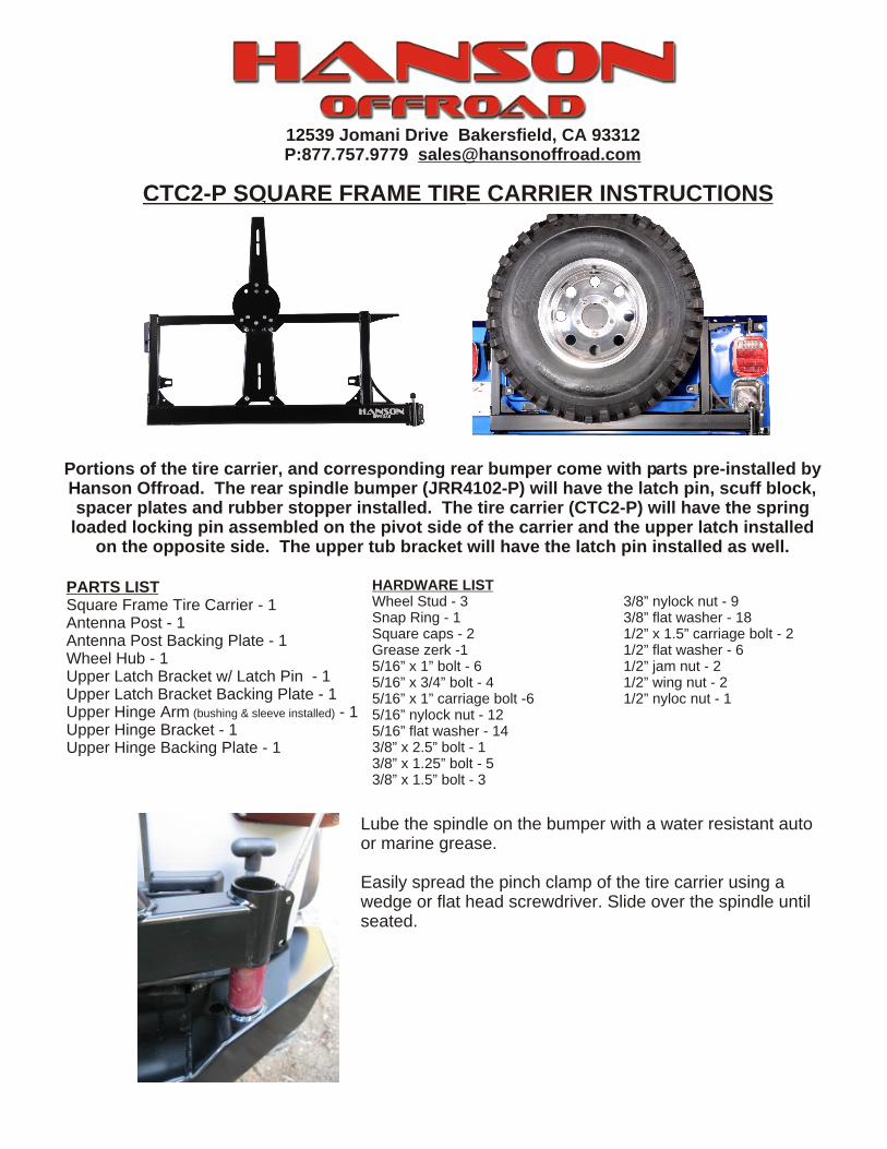
Portions of the tire carrier, and corresponding rear bumper come with parts pre-installed by Hanson Offroad. The rear spindle bumper (JRR4102-P) will have the latch pin, scuff block, spacer plates and rubber stopper installed. The tire carrier (CTC2-P) will have the spring
loaded locking pin assembled on the pivot side of the carrier and the upper latch installed on the opposite side. The upper tub bracket will have the latch pin installed as well.
HARDWARE LISTWheel Stud - 3 3/8” nylock nut - 9Snap Ring - 1 3/8” flat washer - 18Square caps - 2 1/2” x 1.5” carriage bolt - 2Grease zerk -1 1/2” flat washer - 65/16” x 1” bolt - 6 1/2” jam nut - 25/16” x 3/4” bolt - 4 1/2” wing nut - 25/16” x 1” carriage bolt -6 1/2” nyloc nut - 15/16” nylock nut - 125/16” flat washer - 143/8” x 2.5” bolt - 13/8” x 1.25” bolt - 53/8” x 1.5” bolt - 3
Lube the spindle on the bumper with a water resistant auto or marine grease.
Easily spread the pinch clamp of the tire carrier using a wedge or flat head screwdriver. Slide over the spindle until seated.

Bolt the upper hinge arm to the tire carrier using two of the 3/8” x 1.25” bolts and corresponding flat washers and lock nuts.Then hand tighten the upper hinge arm bracket to the upper hinge using the supplied 3/8” x 2.5” bolt, flat washers, and lock nut.Push the bracket firmly against the tub of the Jeep and mark the center of both holes to be drilled.
NOTE: This carrier will work with aftermarket bedsides as the hinge is adjustable in the bracket.
Insert the grease zerk on the top of the spindle as shown
Install the snap ring as shown with a pair of snap ring pliers
Using two of the 5/16” x 1” bolt, four flat washers and two lock nuts install through the pinch clamp portion of the spindle as shown. Snug but do not tighten. This bolt point is used to adjust pivot tension as well as overall placement
Tightening the top bolt will raise the carrierTightening the bottom bolt will lower the carrier
Mount the antenna post to the center of the tire carrier using the antenna post backing plate as shown to brace the entire assembly. The top two holes will use the 5/16” x 3/4” bolts and the bottom will use the 5/16” x 1” bolts..
Secure the bottom of the antenna post to the tire carrier using the supplied 5/16” x 3/4” bolts, washers and lock nuts.
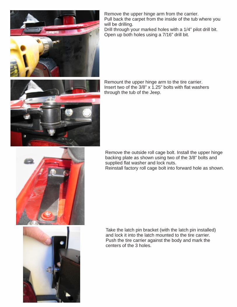
Remove the outside roll cage bolt. Install the upper hinge backing plate as shown using two of the 3/8” bolts and supplied flat washer and lock nuts.Reinstall factory roll cage bolt into forward hole as shown.
Remount the upper hinge arm to the tire carrier.Insert two of the 3/8” x 1.25” bolts with flat washers through the tub of the Jeep.
Remove the upper hinge arm from the carrier.Pull back the carpet from the inside of the tub where you will be drilling.Drill through your marked holes with a 1/4” pilot drill bit.Open up both holes using a 7/16” drill bit.
Take the latch pin bracket (with the latch pin installed) and lock it into the latch mounted to the tire carrier.Push the tire carrier against the body and mark the centers of the 3 holes.

Install the latch bracket backing plate inside the fenderwell as shown using two of the supplied 3/8” bolts, washers, and lock nuts. Then pull back the carpet from the cargo area a pilot the holes in the bracket through to the cargo area.
Drill through the tub with a 1/4” pilot bit. Once all three holes have been started, open them all up using a 7/16” drill bit.
Drill through the piloted holes with a 7/16” drill bit as shown in the photo
Insert three of the 3/8” x 1.25” bolts with flat washers. Tighten the upper bolt with a flat washer and lock nut.

Using the spare tire, set the rim down on a flat surface and measure to the backside of the rim. Subtract 3/4” and use this measurement in the next step.
Place the carpet back in place around the latch bracket and the roll cage.
Insert two of the 3/8” x 1.25” bolts with the flat washers from the cargo area into the rear fender well. Tighten the two bolts in the fenderwell with supplied flat washer and lock nuts.
With the latch bracket in place, adjust the position of the pin so that it completely engages the latch mechanism. Additionally, the tire carrier should sit loaded against the rubber stopper on the bumper. This is critical to minimize vibrations.

Before installing the Hi-Lift jack to the tire carrier, remove the foot pad and secure to the antenna post using a 5/16” x 1” carriage bolt through the center as shown in the photo.
Locate and install the 1/2” carriage bolt through the 2 lower Hi-Lift tabs. Install a flat washer and included jam nut (thin hex nut). The Hi-Lift will mount to this stud and secure with a wing nut on the outside.
NOTE: This step can be complete with a basic h-frame press, securely mounted vice or while installed on the tire carrier. The included wheel studs will need to be pressed into the wheel hub in the correct pattern for your wheel.
Once installed, mount wheel/tire combination and load the tire against the carrier itself. This is best done as a 2 person job with one person pushing the carrier against the carrier/bumper and the other tightening the wheel hub bolts where it connects to the antenna post.
Using the measurement from the previous step, measure and adjust the wheel hub and antenna post to the right offset. The wheel hubs will secure to the antenna post using the 5/16 x ¾ carriage bolt, flat washers and lock nuts.
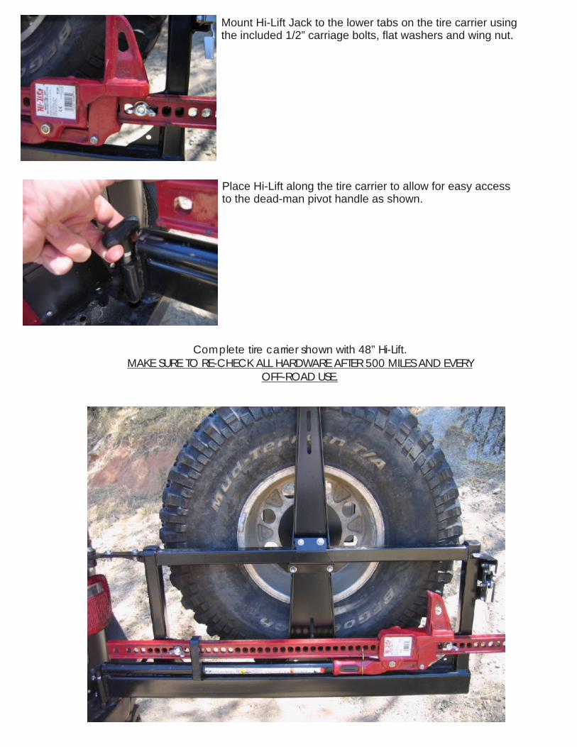
Complete tire carrier shown with 48” Hi-Lift. MAKE SURE TO RE-CHECK ALL HARDWARE AFTER 500 MILES AND EVERY
OFF-ROAD USE.
Mount Hi-Lift Jack to the lower tabs on the tire carrier using the included 1/2” carriage bolts, flat washers and wing nut.
Place Hi-Lift along the tire carrier to allow for easy access to the dead-man pivot handle as shown.